EP3055923B1 - Lüfter mit axialfluss-elektromotor - Google Patents
Lüfter mit axialfluss-elektromotor Download PDFInfo
- Publication number
- EP3055923B1 EP3055923B1 EP14851743.6A EP14851743A EP3055923B1 EP 3055923 B1 EP3055923 B1 EP 3055923B1 EP 14851743 A EP14851743 A EP 14851743A EP 3055923 B1 EP3055923 B1 EP 3055923B1
- Authority
- EP
- European Patent Office
- Prior art keywords
- fan
- motor
- stator
- rear plate
- coupled
- Prior art date
- Legal status (The legal status is an assumption and is not a legal conclusion. Google has not performed a legal analysis and makes no representation as to the accuracy of the status listed.)
- Active
Links
- 230000004907 flux Effects 0.000 title claims description 21
- 238000004804 winding Methods 0.000 description 21
- 230000000712 assembly Effects 0.000 description 14
- 238000000429 assembly Methods 0.000 description 14
- 238000000034 method Methods 0.000 description 8
- 238000004519 manufacturing process Methods 0.000 description 6
- 239000000463 material Substances 0.000 description 5
- RYGMFSIKBFXOCR-UHFFFAOYSA-N Copper Chemical compound [Cu] RYGMFSIKBFXOCR-UHFFFAOYSA-N 0.000 description 3
- 229910000831 Steel Inorganic materials 0.000 description 3
- 229910052802 copper Inorganic materials 0.000 description 3
- 239000010949 copper Substances 0.000 description 3
- 230000008878 coupling Effects 0.000 description 3
- 238000010168 coupling process Methods 0.000 description 3
- 238000005859 coupling reaction Methods 0.000 description 3
- 229910052751 metal Inorganic materials 0.000 description 3
- 239000002184 metal Substances 0.000 description 3
- 239000010959 steel Substances 0.000 description 3
- 229910000851 Alloy steel Inorganic materials 0.000 description 2
- XEEYBQQBJWHFJM-UHFFFAOYSA-N Iron Chemical compound [Fe] XEEYBQQBJWHFJM-UHFFFAOYSA-N 0.000 description 2
- 239000000853 adhesive Substances 0.000 description 2
- 230000001070 adhesive effect Effects 0.000 description 2
- 230000007423 decrease Effects 0.000 description 2
- 230000014759 maintenance of location Effects 0.000 description 2
- 229910001172 neodymium magnet Inorganic materials 0.000 description 2
- 230000010349 pulsation Effects 0.000 description 2
- 239000002356 single layer Substances 0.000 description 2
- 229910000859 α-Fe Inorganic materials 0.000 description 2
- QJVKUMXDEUEQLH-UHFFFAOYSA-N [B].[Fe].[Nd] Chemical compound [B].[Fe].[Nd] QJVKUMXDEUEQLH-UHFFFAOYSA-N 0.000 description 1
- 238000004378 air conditioning Methods 0.000 description 1
- KPLQYGBQNPPQGA-UHFFFAOYSA-N cobalt samarium Chemical compound [Co].[Sm] KPLQYGBQNPPQGA-UHFFFAOYSA-N 0.000 description 1
- 239000002131 composite material Substances 0.000 description 1
- 238000001816 cooling Methods 0.000 description 1
- 238000010438 heat treatment Methods 0.000 description 1
- 229910052742 iron Inorganic materials 0.000 description 1
- 239000010410 layer Substances 0.000 description 1
- 229910001004 magnetic alloy Inorganic materials 0.000 description 1
- 230000001681 protective effect Effects 0.000 description 1
- 229910000938 samarium–cobalt magnet Inorganic materials 0.000 description 1
- 238000005245 sintering Methods 0.000 description 1
- 239000007787 solid Substances 0.000 description 1
- 239000013589 supplement Substances 0.000 description 1
- 238000009423 ventilation Methods 0.000 description 1
- 239000002699 waste material Substances 0.000 description 1
- 238000003466 welding Methods 0.000 description 1
Images


Classifications
-
- F—MECHANICAL ENGINEERING; LIGHTING; HEATING; WEAPONS; BLASTING
- F04—POSITIVE - DISPLACEMENT MACHINES FOR LIQUIDS; PUMPS FOR LIQUIDS OR ELASTIC FLUIDS
- F04D—NON-POSITIVE-DISPLACEMENT PUMPS
- F04D25/00—Pumping installations or systems
- F04D25/02—Units comprising pumps and their driving means
- F04D25/06—Units comprising pumps and their driving means the pump being electrically driven
- F04D25/0606—Units comprising pumps and their driving means the pump being electrically driven the electric motor being specially adapted for integration in the pump
- F04D25/0653—Units comprising pumps and their driving means the pump being electrically driven the electric motor being specially adapted for integration in the pump the motor having a plane air gap, e.g. disc-type
-
- H—ELECTRICITY
- H02—GENERATION; CONVERSION OR DISTRIBUTION OF ELECTRIC POWER
- H02K—DYNAMO-ELECTRIC MACHINES
- H02K1/00—Details of the magnetic circuit
- H02K1/06—Details of the magnetic circuit characterised by the shape, form or construction
- H02K1/12—Stationary parts of the magnetic circuit
- H02K1/14—Stator cores with salient poles
- H02K1/146—Stator cores with salient poles consisting of a generally annular yoke with salient poles
- H02K1/148—Sectional cores
-
- F—MECHANICAL ENGINEERING; LIGHTING; HEATING; WEAPONS; BLASTING
- F04—POSITIVE - DISPLACEMENT MACHINES FOR LIQUIDS; PUMPS FOR LIQUIDS OR ELASTIC FLUIDS
- F04D—NON-POSITIVE-DISPLACEMENT PUMPS
- F04D17/00—Radial-flow pumps, e.g. centrifugal pumps; Helico-centrifugal pumps
- F04D17/08—Centrifugal pumps
- F04D17/16—Centrifugal pumps for displacing without appreciable compression
-
- F—MECHANICAL ENGINEERING; LIGHTING; HEATING; WEAPONS; BLASTING
- F04—POSITIVE - DISPLACEMENT MACHINES FOR LIQUIDS; PUMPS FOR LIQUIDS OR ELASTIC FLUIDS
- F04D—NON-POSITIVE-DISPLACEMENT PUMPS
- F04D25/00—Pumping installations or systems
- F04D25/02—Units comprising pumps and their driving means
- F04D25/06—Units comprising pumps and their driving means the pump being electrically driven
- F04D25/068—Mechanical details of the pump control unit
-
- F—MECHANICAL ENGINEERING; LIGHTING; HEATING; WEAPONS; BLASTING
- F04—POSITIVE - DISPLACEMENT MACHINES FOR LIQUIDS; PUMPS FOR LIQUIDS OR ELASTIC FLUIDS
- F04D—NON-POSITIVE-DISPLACEMENT PUMPS
- F04D25/00—Pumping installations or systems
- F04D25/02—Units comprising pumps and their driving means
- F04D25/06—Units comprising pumps and their driving means the pump being electrically driven
- F04D25/0693—Details or arrangements of the wiring
-
- F—MECHANICAL ENGINEERING; LIGHTING; HEATING; WEAPONS; BLASTING
- F04—POSITIVE - DISPLACEMENT MACHINES FOR LIQUIDS; PUMPS FOR LIQUIDS OR ELASTIC FLUIDS
- F04D—NON-POSITIVE-DISPLACEMENT PUMPS
- F04D25/00—Pumping installations or systems
- F04D25/02—Units comprising pumps and their driving means
- F04D25/08—Units comprising pumps and their driving means the working fluid being air, e.g. for ventilation
- F04D25/12—Units comprising pumps and their driving means the working fluid being air, e.g. for ventilation the unit being adapted for mounting in apertures
-
- F—MECHANICAL ENGINEERING; LIGHTING; HEATING; WEAPONS; BLASTING
- F04—POSITIVE - DISPLACEMENT MACHINES FOR LIQUIDS; PUMPS FOR LIQUIDS OR ELASTIC FLUIDS
- F04D—NON-POSITIVE-DISPLACEMENT PUMPS
- F04D29/00—Details, component parts, or accessories
- F04D29/05—Shafts or bearings, or assemblies thereof, specially adapted for elastic fluid pumps
- F04D29/056—Bearings
- F04D29/059—Roller bearings
-
- F—MECHANICAL ENGINEERING; LIGHTING; HEATING; WEAPONS; BLASTING
- F04—POSITIVE - DISPLACEMENT MACHINES FOR LIQUIDS; PUMPS FOR LIQUIDS OR ELASTIC FLUIDS
- F04D—NON-POSITIVE-DISPLACEMENT PUMPS
- F04D29/00—Details, component parts, or accessories
- F04D29/26—Rotors specially for elastic fluids
- F04D29/28—Rotors specially for elastic fluids for centrifugal or helico-centrifugal pumps for radial-flow or helico-centrifugal pumps
- F04D29/281—Rotors specially for elastic fluids for centrifugal or helico-centrifugal pumps for radial-flow or helico-centrifugal pumps for fans or blowers
-
- F—MECHANICAL ENGINEERING; LIGHTING; HEATING; WEAPONS; BLASTING
- F04—POSITIVE - DISPLACEMENT MACHINES FOR LIQUIDS; PUMPS FOR LIQUIDS OR ELASTIC FLUIDS
- F04D—NON-POSITIVE-DISPLACEMENT PUMPS
- F04D29/00—Details, component parts, or accessories
- F04D29/40—Casings; Connections of working fluid
- F04D29/42—Casings; Connections of working fluid for radial or helico-centrifugal pumps
- F04D29/4206—Casings; Connections of working fluid for radial or helico-centrifugal pumps especially adapted for elastic fluid pumps
- F04D29/4226—Fan casings
-
- H—ELECTRICITY
- H02—GENERATION; CONVERSION OR DISTRIBUTION OF ELECTRIC POWER
- H02K—DYNAMO-ELECTRIC MACHINES
- H02K1/00—Details of the magnetic circuit
- H02K1/06—Details of the magnetic circuit characterised by the shape, form or construction
- H02K1/12—Stationary parts of the magnetic circuit
- H02K1/18—Means for mounting or fastening magnetic stationary parts on to, or to, the stator structures
- H02K1/182—Means for mounting or fastening magnetic stationary parts on to, or to, the stator structures to stators axially facing the rotor, i.e. with axial or conical air gap
-
- H—ELECTRICITY
- H02—GENERATION; CONVERSION OR DISTRIBUTION OF ELECTRIC POWER
- H02K—DYNAMO-ELECTRIC MACHINES
- H02K11/00—Structural association of dynamo-electric machines with electric components or with devices for shielding, monitoring or protection
- H02K11/30—Structural association with control circuits or drive circuits
- H02K11/33—Drive circuits, e.g. power electronics
-
- H—ELECTRICITY
- H02—GENERATION; CONVERSION OR DISTRIBUTION OF ELECTRIC POWER
- H02K—DYNAMO-ELECTRIC MACHINES
- H02K15/00—Methods or apparatus specially adapted for manufacturing, assembling, maintaining or repairing of dynamo-electric machines
- H02K15/14—Casings; Enclosures; Supports
-
- H—ELECTRICITY
- H02—GENERATION; CONVERSION OR DISTRIBUTION OF ELECTRIC POWER
- H02K—DYNAMO-ELECTRIC MACHINES
- H02K7/00—Arrangements for handling mechanical energy structurally associated with dynamo-electric machines, e.g. structural association with mechanical driving motors or auxiliary dynamo-electric machines
- H02K7/14—Structural association with mechanical loads, e.g. with hand-held machine tools or fans
Definitions
- the embodiments described herein relate generally to axial flux electrical motors, and more particularly, to axial flux electrical motor and fan assemblies for use in forced air or air circulating systems.
- air propulsion units In addition to providing movement of air for such systems, air propulsion units may be used in combination with condenser units or to supplement other heat transfer operations.
- Some known air propulsion units are motor driven fans. These fans may be, for example, a centrifugal impeller type fan driven by a radial flux motor.
- some known radial flux motors and/or their mounting components extend a distance into the fan that restricts entering and exiting air and produces aerodynamic losses that negatively affect the overall performance of the fan.
- At least some known motors may generate undesired torque ripple pulsations, which may cause vibrations, and potentially motor noise, any amount of which may be objectionable to a user. Further, the torque ripple pulsations of the motor may be transmitted to the fan and cause additional unacceptable noise.
- centrifugal fans use one or a combination of three basic fan blade designs: radial, forward curved, and backward curved.
- backward curved fans also known as plug fans, are more efficient than forward curved fans and radial bladed fans.
- US 2013/170945 A1 discloses a centrifugal fan driven by a shaftless axial flux electric motor.
- the invention is a fan assembly according to claim 1.
- a backward curved plug fan assembly in another aspect, not part of the invention, includes an axis of rotation and a fan including an inlet ring and a rear plate that together define an inner fan chamber.
- the fan assembly also includes an axial flux motor coupled to the rear plate to facilitate rotation of the fan about the axis.
- the motor extends a predetermined distance from the rear plate into the fan chamber to facilitate reducing interference between the motor and an airflow within the fan chamber.
- a method for assembling a backward curved plug fan assembly includes providing a fan including an inlet ring and a rear plate that together define an inner fan chamber.
- the method also includes coupling an axial flux motor to the rear plate such that the motor is positioned entirely outside the fan chamber to facilitate preventing interference between the motor and an airflow within the fan chamber.
- the embodiments described herein relate generally to axial flux electrical motors, and more particularly, to axial flux electrical motor and fan assemblies for use in forced air or air circulating systems.
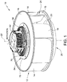
- Fig. 1 is a perspective view of one embodiment of a centrifugal fan assembly 10, and Fig. 2 is a cross-section view of fan assembly 10.
- fan assembly 10 is configured to produce a flow of air for a forced air system, e.g., a commercial or industrial HVAC system.
- Fan assembly 10 includes a fan 12 that includes a plurality of blades 14 coupled between a rear plate 16 and an inlet ring 18.
- Inlet ring 18 includes a central air inlet 20.
- fan 12 is a backward curved plug fan.
- fan 12 may have any suitable blade shape, for example a backward curved blade, an airfoil blade, a backward inclined blade, a forward curved blade, and a radial blade, that enables fan assembly 10 to operate as described herein.
- Rear plate 16 and inlet ring 18 are coaxial or substantially coaxial and configured to rotate about a center axis 22.
- Blades 14 are attached to rear plate 16 and/or inlet ring 18 such that each blade 14 extends between rear plate 16 and inlet ring 18.
- each blade 14 may be attached to rear plate 16 and/or inlet ring 18 via features formed in rear plate 16 and/or inlet ring 18 such as an opening, e.g., a groove or a slot, configured to restrict an amount of movement of blade 14 between rear plate 16 and inlet ring 18 while permitting blades 14 to operate as described herein.
- blades 14 are configured to pull in air along center axis 22 and eject the air radially outward through an outlet 24 located between adjacent blades 14.
- Blades 14 may be coupled to rear plate 16 and/or inlet ring 18 in any manner that permits fan 12 to operate as described herein.
- fan 12 may include only one of inlet ring 18 and rear plate 16.
- Blades 14 are configured to pull the air through inlet 20 into a central chamber 26 of fan 12.
- the air passes through channels between blades 14 and is forced outward through outlet 24 due to the centrifugal force generated by rotating blades 14.
- the volume of airflow forced outward changes with respect to the speed of the fan's rotation.
- Fan assembly 10 also includes a motor 28 coupled to rear plate 16 of fan 12.
- motor 28 is an axial flux electric motor configured to rotate fan 12 about axis 22.
- Motor 28 includes a stator 30, a rotor assembly 32, and a bearing assembly 34 coupled radially therebetween.
- Stator 30, rotor assembly 32, and bearing assembly 34 each include a concentric opening 36 oriented about axis 22.
- Stator 30 includes a plurality of circumferentially-spaced stator teeth 38 that extend in a direction parallel to axis of rotation 22 such that a slot (not shown) is formed between each adjacent tooth 38.
- stator 30 is a strip wound core manufactured from a long ribbon made of steel or soft magnetic composite (SMC) material wound into a toroidal shape.
- SMC soft magnetic composite
- Copper windings 40 each include an opening (not shown) that closely conforms to an external shape of one of a plurality of stator teeth 38 such that each stator tooth 38 is configured to be positioned within a winding 40.
- Motor 28 may include one winding 40 per stator tooth 38 or one winding 40 positioned on every other tooth 38.
- Each winding 40 may be insulated from adjacent windings 40 by an insulating layer (not shown).
- a motor controller 42 is coupled to at least one winding 40, and is configured to apply a voltage to one or more of windings 40 at a time for commutating windings in a preselected sequence to rotate rotor assembly 32 about axis 22.
- Rotor assembly 32 includes a rotor disk 44 having an axially inner surface 46 and a radially inner wall 48 that at least partially defines opening 36.
- Rotor assembly 32 also includes a plurality of permanent magnets 50 coupled to inner surface 46 of rotor disk 44.
- magnets 50 are coupled to rotor disk 44 using an adhesive.
- magnets 50 are coupled to disk 44 using any retention method that facilitates operation of motor 28 as described herein.
- the plurality of permanent magnets 50 are symmetrical, which facilitates manufacturing a single magnet design for use with each magnet 50 within the plurality of permanent magnets 50.
- each magnet 50 has a substantially flat profile which minimizes waste during manufacturing, and therefore, minimizes cost.
- Magnets 50 may be composed of Neodymium Iron Boron (NdFeB) material, however alternative materials such as, but not limited to, Samarium Cobalt or Ferrite are suitable.
- Rotor assembly 32 also includes a primary bearing locator 52 proximate radially inner wall 48 for facilitating proper positioning of bearing assembly 34.
- rotor disk 44 is machined and/or cast from a solid metal, such as, but not limited to steel and/or iron.
- rotor disk 44 is manufactured using a sintering process from, for example, Soft Magnetic Alloy (SMA), SMC, and/or powdered ferrite materials.
- stator 30 is comprised of a metal, such as a steel alloy, that provides a magnetic attraction between permanent magnets 50 and stator 30 to retain rotor disk 44, bearing assembly 34, and stator 30 in place within motor 28 such that motor 28 does not require a shaft.
- Fan assembly 10 further includes a hub 54 and a midshield 56 that facilitate coupling motor 28 and controller 42 to fan 12.
- Midshield 56 is coupled between controller 42 and stator 30 and is configured to maintain a stationary position of stator 30 and bearing assembly 34 during rotation of fan 12 and rotor assembly 32.
- Midshield 56 includes a secondary bearing locator 58 extending from an inner surface 60 of midshield 56 that facilitates retaining bearing assembly 34 in place.
- Bearing assembly 34 is secured between secondary bearing locator 58 and primary bearing locator 52 and includes an inner race 62, an outer race 64, and a plurality of ball bearings 66 positioned therebetween.
- Primary bearing locator 52 engages and locates bearing assembly 34 by engaging inner race 62.
- Secondary bearing locator 58 engages outer race 64 to further position and secure bearing assembly 34 such that bearing assembly 34 is positioned radially inward from and concentric with stator 30.
- Midshield 56 also includes a plurality of fins 70 (best shown in Fig. 1 ) that facilitate cooling motor 28 and a substantially annular protection flange 72 extending axially inward from inner surface 60 toward chamber 26 of fan 12.
- Flange 72 extends axially inward a distance substantially equal to a length of each stator tooth 38 such that flange 72 protects the plurality of stator teeth 38 from rotating portions of fan assembly 10, such as hub 54 and fan 12.
- Midshield also includes a substantially circular groove 74 positioned immediately radially outward of flange 72 and configured to accept at least a portion of hub 54.
- hub 54 is substantially bowl-shaped and is configured to couple motor 28 to fan 12. More specifically, hub 54 is configured to couple rotor disk 44 of rotor assembly 32 to rear plate 16 of fan 12 to facilitate rotation of fan 12 about axis 22.
- Hub 54 includes a substantially circular end portion 76 that is configured to be seated within groove 74 of midshield 56. Hub 54 also includes a radial flange 78 extending radially outward from hub 54 proximate end portion 76. Radial flange 78 includes a plurality of openings (not shown) that correspond to a plurality openings (not shown) in rear plate 16 of fan 12.
- radial flange 78 is coupled to fan rear plate 16 by threading a fastener (not shown) through each concentric opening on radial flange 78 and rear plate 16.
- radial flange 78 may be coupled to rear plate 16 in any manner, such as by welding, that facilitates operation of fan assembly 10 as described herein.
- Radial flange 78 is coupled opposite blades 14 to rear plate 16 such that hub 54 extends through an opening 80 in rear plate 16 and into chamber 26 of fan 12. Opening 80 has a standard size diameter that may be found in at least some known centrifugal plug fans. The standard diameter of opening 80 facilitates removing a first motor and installing motor 28 within fan assembly 10.
- hub 54 includes a bowl-shaped portion 82 that extends a distance 84 into fan chamber 26 from rear plate 16. Distance 84 is less than a distance that at least some known motors extend into chamber 26 of fan 12. More specifically, at least some known radial flux motors extend a distance farther than distance 84 into chamber 26. The farther a motor extends into chamber 26, the more the motor will interfere with the airflow within chamber 26.
- hub bowl portion 82 extends approximately 30 millimeters into fan chamber 26 such that bowl portion 82 reduces or prevents interference between the airflow and motor 26, which facilitates increasing fan assembly 10 efficiency. Furthermore, hub bowl portion 82 includes a contoured shape that is configured to facilitate a smooth airflow around hub 54.
- Hub bowl portion 82 also includes an axial flange 86 that extends substantially axially toward rotor assembly 32 from bowl portion 82.
- Axial flange 86 is configured to be coupled to rotor disk 44 to facilitate rotation of fan 12.
- windings 40 coupled to stator 30 are energized in a chronological sequence by controller 42 that provides an axial magnetic field which moves clockwise or counterclockwise around stator 30 depending on the pre-determined sequence or order in which windings 40 are energized. This moving magnetic field intersects with the flux field created by the plurality of permanent magnets 50 to cause rotor assembly 32 to rotate about axis 22 relative to stator 30 in the desired direction to develop a torque which is a direct function of the intensities or strengths of the magnetic fields.
- hub 54 is coupled to rotor disk 44 via axial flange 86, rotation of rotor assembly 32 facilitates rotation of hub 54.
- rear plate 12 is coupled to hub 54, such as with radial flange 78, rotation of hub 54 facilitates rotation of fan 12.
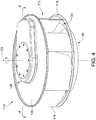
- Fig. 4 is a perspective view of an alternative embodiment of a centrifugal fan assembly 110, which is an embodiment of the invention
- Fig. 5 is a cross-sectional view of fan assembly 110.
- fan assembly 110 is configured to produce a flow of air for a forced air system, e.g., a commercial or industrial HVAC system.
- Fan assembly 110 includes a fan 112 that includes a plurality of blades 114 coupled between a rear plate 116 and an inlet ring 118.
- Inlet ring 118 includes a central air inlet 120.
- fan 112 is a backward curved plug fan.
- fan 112 may have any suitable blade shape, for example a backward curved blade, an airfoil blade, a backward inclined blade, a forward curved blade, and a radial blade, that enables fan assembly 110 to operate as described herein.
- Rear plate 116 and inlet ring 118 are coaxial or substantially coaxial and configured to rotate about a center axis 122.
- Blades 114 are attached to rear plate 116 and/or inlet ring 118 such that a longitudinal axis of blades 114 is substantially parallel to center axis 122.
- each blade 114 may be attached to rear plate 116 and/or inlet ring 118 via features formed in rear plate 116 and/or inlet ring 118 such as an opening, e.g., a groove or a slot, configured to restrict an amount of movement of blade 114 between rear plate 116 and inlet ring 118 while permitting blades 114 to operate as described herein.
- blades 114 are configured to pull in air along center axis 122 and eject the air radially outward through an outlet 124 located between adjacent blades 114.
- Blades 114 may be coupled to rear plate 116 and/or inlet ring 118 in any manner that permits fan 112 to operate as described herein.
- fan 112 may include only one of inlet ring 118 and rear plate 116.
- fan assembly 110 when fan assembly 110 operates, air enters through central air inlet 120 and is deflected radially outward from central axis 122 of fan assembly 110 towards blades 114. Blades 114 are configured to pull the air through inlet 120 into an inner fan chamber 126 of fan 112. The air passes through channels between blades 14 and is forced outwards through outlet 124 due to the centrifugal force generated by rotating blades 114. In addition, in some known fans, the volume of airflow forced outwards changes with respect to the speed of the fan's rotation.
- Fig. 6 is a perspective cross-sectional view of fan assembly 110 that also includes a motor assembly 128 coupled to rear plate 116 of fan 112.
- motor assembly 128 includes a motor 130, a motor case 132, and a motor controller 134.
- Motor 130 is an axial flux electric motor configured to rotate fan 112 about axis 122.
- Motor 130 includes a stator 136, a rotor assembly 138, and a bearing assembly 140 coupled radially therebetween.
- Stator 136, rotor assembly 138, and bearing assembly 140 each include a concentric opening 142 oriented about axis 122.
- Stator 136 includes a plurality of circumferentially-spaced stator teeth 144 that extend in a direction parallel to axis of rotation 122 such that a slot (not shown) is formed between each adjacent tooth 144. Similar to stator 30 (shown in Fig. 1 ), stator 136 is a strip wound core manufactured from a long ribbon made of steel or SMC material wound into a toroidal shape.
- Motor 130 also includes a plurality of copper windings 146 that each include an opening (not shown) closely conforming to an external shape of one of a plurality of stator teeth 144 such that each stator tooth 144 is configured to be positioned within a winding 146.
- Motor 130 may include one winding 146 per stator tooth 144 or one winding 146 positioned on every other tooth 144.
- Motor controller 134 is coupled to at least one winding 146 such that motor controller 134 is positioned adjacent motor 130, and is configured to apply a voltage to one or more of windings 146 at a time for commutating windings 146 in a preselected sequence to rotate rotor assembly 138 about axis 122.
- Rotor assembly 138 includes a rotor disk 148, substantially similar to rotor disk 44 (shown in Fig. 3 ), and an annular magnet retainer 150 configured to couple a plurality of permanent magnets (not shown) to rotor disk 148.
- the magnets are substantially similar to permanent magnets 50 (shown in Fig. 3 ).
- the magnets may be coupled to rotor disk 148 using an adhesive.
- the magnets are coupled to disk 148 using any retention method that facilitates operation of motor 130 as described herein.
- Stator 136 is comprised of a metal, such as a steel alloy, that provides a magnetic attraction between the permanent magnets and stator 136 to retain rotor disk 148, bearing assembly 140, and stator 136 in place within motor 130 such that motor 130 does not require a shaft.
- Rotor disk 144 also includes a primary bearing locator 152 configured to properly position bearing assembly 140.
- Primary bearing locator 152 includes a radially inner wall 154 that at least partially defines opening 142.
- fan assembly 110 further includes motor case 134 configured to provide a protective covering for motor 130 and controller 134.
- Case 132 is a unitary cast component that includes a cap portion 165 oriented substantially parallel with rear plate 116, and an integrated flange 158 that extends axially towards rear plate 116 from a circumferential edge of cap portion 156. Case 132 is configured to maintain a stationary position of stator 136 and bearing assembly 140 during rotation of fan 112 and rotor assembly 138.
- Case 132 also includes a secondary bearing locator 160 extending from an inner surface 162 of case 132 that facilitates retaining bearing assembly 140 in place. More specifically, secondary bearing locator 160 engages an outer race 164 of bearing assembly 140 and primary bearing locator 152 engages an inner race 166 of bearing assembly 140 such that bearing assembly 140 is positioned radially inward from and concentric with stator 136.
- Case 132 is coupled to stator 136 via a plurality of fasteners 168 extending through an axially outermost surface 170 of cap portion 156.
- case 132 is coupled to motor 130 such that cap portion 156 is positioned minimal distance from rear plate 116.
- outer surface 170 of cap portion 165 is spaced a distance 172 in a range of between approximately 20 millimeters (mm) to approximately 50mm away from rear plate 116, and more precisely, outer surface 170 of cap portion is spaced a distance 172 in a range of between approximately 36mm to approximately 40mm away from rear plate 116.
- gap 174 defines a distance in a range of between approximately 10mm and approximately 15mm. In other embodiments, gap 174 defines any distance that facilitates operation of fan assembly 110 as described herein. As such, case 132 is not directly coupled to rear plate 116, or any other portion, of fan 112.
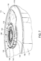
- motor controller 134 is coupled within motor assembly 128 adjacent to motor 130 such that controller 134 is positioned radially outward from and substantially planar with stator 136. A such, controller 134 is not oriented axially from motor 130, as in fan assembly 10 (shown in Fig. 1 ). Controller 134 includes an arcuate cutout 176, as best shown in Fig. 7 having case 132 removed for clarity. Cutout 176 is configured to correspond to a circumference of motor 130, more specifically, to a circumference of stator 136 such that controller 134 is oriented at least partially about motor 130. In one embodiment, controller 134 is a substantially planar printed circuit board that allows for significant reduction in motor assembly thickness, which may be desired for some users. In other embodiments, controller 134 may be positioned at any location in motor assembly 128 and have any thickness that facilitates operation of fan assembly 110 as described herein.
- motor assembly 128 is coupled to fan 112 such that motor assembly 128 is positioned entirely outside fan chamber 126. That is, motor assembly 128 is coupled to fan 112 such that no portion of motor assembly 128 extends through rear plate 116 to intrude into chamber 126.
- air is able to flow within chamber 126 free of disturbances and without being directed around a motor, as is the case in at least some known fan assemblies having radial flux motor.
- the farther a motor extends into a fan chamber the more the motor will interfere with the airflow within the chamber. Such interference generally results in a loss in fan efficiency. Therefore, zero intrusion of motor assembly 128 into chamber 126 prevents such a loss in efficiency and provides for an increased efficiency of fan assembly 110 as compared to at least some known fan assemblies having radial flux motors that extend a significant distance into the fan chamber.
- fan assembly 110 does not include hub 54 or midshield 56 (both shown in Fig. 3 ) to couple motor assembly 128 to fan 112.
- motor assembly 128 is coupled directly to rear plate 116 of fan 112 to facilitate rotation of fan 112 about center axis 122.
- rotor disk 138 is coupled directly to rear plate 116 via a plurality of fasteners 178 threaded through corresponding openings formed in rear plate 116.
- rotor disk 138 may be coupled to rear plate 116 in any manner that facilitates operation of fan assembly 110 as described herein.
- Rotor disk 138 includes an axial flange 180 that extends from an inner surface 182 of rotor disk 138 to an outer surface 184 of rear plate 116.
- Flange 180 is configured to space rotor disk 138 a distance from rear plate 116 to facilitate proper alignment or rotor assembly 138 during operation of fan assembly 110.
- windings 146 coupled to stator 136 are energized in a chronological sequence by controller 134 that provides an axial magnetic field which moves clockwise or counterclockwise around stator 136 depending on the pre-determined sequence or order in which windings 146 are energized.
- This moving magnetic field intersects with the flux field created by the plurality of permanent magnets to cause rotor assembly 138 to rotate about axis 122 relative to stator 136 in the desired direction to develop a torque which is a direct function of the intensities or strengths of the magnetic fields.
- rotor disk 148 of rotor assembly 138 is coupled directly to rear plate 116 of fan 112, rotation of rotor disk 148 facilitates rotation of fan 112.
- Fig. 8 illustrates a single stator tooth 200 of the pluralities of stator teeth 38 (shown in Fig. 3 ) and 144 (shown in Fig. 6 ).
- Stators 30 shown in Fig. 3
- 136 shown in Fig. 6
- Each stator tooth 200 includes a radially inner surface 202 that at least partially defines an inner diameter (not shown) of stators 30 and 136 and a radially outer surface 204 that at least partially defines an outer diameter (not shown) of stators 30 and 136.
- each tooth 200 includes a top surface 206 proximate rotor assemblies 32 (shown in Fig.
- a radially inner edge 212 is defined at the intersection of radially inner face 202 and top surface 206.
- a radially outer edge 214 is defined at the intersection of radially outer surface 204 and top surface 206.
- a circumferential width of each tooth 200 decreases in the radially inward direction from surface 204 to surface 202.
- each tooth 200 also includes a chamfered portion 216 at the intersection of first side 208 and top surface 206 and also at the intersection of second side 210 and top surface 206.
- teeth 200 may not include chamfered portion 216 such that top surface 206 and circumferential side 208 as well as top surface 206 and side 210 meet at an approximately 90 degree angle.
- Chamfered portion 216 extends substantially an entire radial length of each tooth 200 between inner surface 202 and outer surface 204.
- Chamfered portion 216 facilitates reducing torque ripple generated by motors 28 (shown in Figs. 3 ) and 130 (shown in Fig. 6 ), and therefore reduces the amount of noise produced by fan assemblies 10 (shown in Figs.
- Chamfered portion 216 is formed during manufacturing of stators 30 and 136 such that when the punch and wind machine punches a slot from the ribbon, it also forms the chamfer on each stator tooth 200. Previous attempts to chamfer edges resulted in deformed tooth shape.
- the punch and wind method of manufacturing produces consistent chamfer dimensions along portion 216 without deforming tooth 200. More specifically, the punch and wind machine forms chamfered portions 216 on the circumferential sides 208 and 210 of each tooth 200, while radially inner edge 212 and radially outer edge 214 remain unchanged except to account for chamfered portion 216.
- chamfered portion 216 has a constant width in the range of between approximately 0.5 mm and approximately 2.0 mm between inner surface 202 and outer surface 204. More specifically, chamfered portion 216 has a constant width in the range of between approximately 1.0 mm and approximately 1.5 mm. Alternatively, chamfered portion 216 may have any size chamfer width that facilitates operation of fan assemblies 10 and 110 as described herein. Furthermore, chamfered portion 216 may be tapered to have a varying width that either increases or decreases between surfaces 202 and 204. Chamfered portion 216 produces a significant drop in an amount of motor torque ripple with only minimal losses in actual torque produced by motor 28.
- chamfered portion 216 results in an approximate 50% loss in torque ripple at a chamfer width of 1.14mm, while only resulting in an approximate 2% loss in overall torque production at the chamfer width of 1.14mm.
- Such a reduction in torque ripple results in motors 28 and 130, and therefore fan assemblies 10 and 110, being significantly quieter during operation, while maintaining substantially the same amount of torque production.
- one fan assembly includes an axial flux electric motor and hub that each reduce airflow restriction and downstream disturbances in the airflow, which results in increased efficiency. More specifically, the motor and hub protrude a minimal distance into the chamber of the fan to reduce interference with the airflow as compared to at least some known fan assemblies. Furthermore, the hub is coupled to the rotor assembly and the fan in such a manner that enables the motor to rotate the fan without the use of a driveshaft.
- a fan assembly includes an axial flux motor that is coupled to the fan such that the motor does not intrude into an inner fan chamber and is positioned entirely outside the fan chamber to facilitate preventing interference between the motor and an airflow within the fan chamber, which results in increased efficiency.
- the motor includes a rotor that is coupled directly to a rear plate of the fan to facilitate rotation of the fan.
- the fan assembly also includes a substantially planar motor controller coupled radially outward from a motor stator. The planar controller enables a low profile motor case to cover the motor and the controller such that the case extends a minimal distance from the fan rear plate as compared to some fan assemblies.
- the fan assembly takes up less space within an HVAC system and provides for additional space for added HVAC components.
- the fan assembly contains fewer overall components, which provides for a fan assembly that is less expensive and simpler to assemble than other known fan assemblies.
- stator teeth within the motor are manufactured with chamfers on the circumferential sides of each stator tooth.
- the chamfered stator teeth facilitate reducing the torque ripple, and therefore the noise, generated by the fan assembly, while maintaining a substantially constant amount of torque generated by the motor.
- the embodiments described herein relate to a centrifugal fan assembly and methods of assembling the same. More specifically, the embodiments relate to fan assemblies that includes a backward curved fan and an axial flux electric motor that reduces or prevents airflow interference within the fan and improves the efficiency of the fan assembly. More particularly, one embodiment relates to coupling the motor to the fan such that the motor extends a minimal distance into the fan chamber, and another embodiment, which is an embodiment of the invention, includes the motor coupled to the fan such that the motor does not intrude into the fan chamber.
Claims (9)
- Lüfteranordnung (110) mit einer Drehachse (122) und umfassend:ein Zentrifugallüfterrad (112), umfassend einen Einlassring (118) und eine hintere Platte (116), die zusammen eine innere Lüfterradkammer (126) definieren, wobei das Lüfterrad rückwärts gekrümmte Lüfterflügel (114) aufweist, undeinen Axialflussmotor (130), umfassend einen Stator (136) und einen Rotor (138), wobei der Motor keine Welle beinhaltet, die sich durch diesen erstreckt, wobei der Motor mit der hinteren Platte (116) gekoppelt ist,dadurch gekennzeichnet, dass:
die hintere Platte außer an ihrer radialen Außenkante planar ist und dadurch, dass der Motor vollständig außerhalb der Lüfterradkammer (126) positioniert ist, um das Verhindern von Störungen zwischen dem Motor (130) und einem Luftstrom innerhalb der Lüfterradkammer zu ermöglichen. - Lüfteranordnung nach Anspruch 1, wobei der Motor (130) direkt mit dem Lüfterrad (112) gekoppelt ist, um die Drehung des Lüfterrads zu ermöglichen.
- Lüfteranordnung nach Anspruch 1, wobei der Rotor (138) direkt mit der hinteren Platte (116) gekoppelt ist, um die Drehung des Lüfterrads (112) zu ermöglichen.
- Lüfteranordnung nach Anspruch 1, ferner umfassend eine Motorsteuerung (134), die mit dem Motor (130) gekoppelt ist, wobei die Motorsteuerung vom Stator (136) radial nach außen positioniert ist.
- Lüfteranordnung nach Anspruch 4, wobei der Stator (136) einen Umfang beinhaltet und die Motorsteuerung (134) einen bogenförmigen Ausschnitt (176) mit einer Krümmung beinhaltet, die dem Statorumfang entspricht.
- Lüfteranordnung nach Anspruch 1, ferner umfassend eine Motorsteuerung (134), die mit dem Motor (130) gekoppelt ist, wobei die Motorsteuerung im Wesentlichen planar ist.
- Lüfteranordnung nach Anspruch 1, ferner umfassend ein unitäres Motorgehäuse (132), das mit dem Stator (130) gekoppelt ist, wobei das Motorgehäuse konfiguriert ist, um den Motor (130) abzudecken.
- Lüfteranordnung nach Anspruch 7, wobei das Motorgehäuse (132) eine axial äußerste Oberfläche (170) beinhaltet, die in einem Bereich zwischen etwa 20 Millimetern (mm) und etwa 50 mm von der hinteren Platte (116) positioniert ist.
- Lüfteranordnung nach Anspruch 1, wobei der Stator (136) eine Vielzahl von in Umfangsrichtung beabstandeten Statorzähnen (144) beinhaltet, wobei jeder Zahn der Vielzahl von Zähnen mindestens einen abgeschrägten Abschnitt (216) beinhaltet.
Applications Claiming Priority (2)
| Application Number | Priority Date | Filing Date | Title |
|---|---|---|---|
| US201361889317P | 2013-10-10 | 2013-10-10 | |
| PCT/AU2014/000455 WO2015051396A1 (en) | 2013-10-10 | 2014-04-18 | Axial flux electrical motor and fan assembly and methods of assembling the same |
Publications (3)
| Publication Number | Publication Date |
|---|---|
| EP3055923A1 EP3055923A1 (de) | 2016-08-17 |
| EP3055923A4 EP3055923A4 (de) | 2017-03-08 |
| EP3055923B1 true EP3055923B1 (de) | 2020-12-16 |
Family
ID=52812351
Family Applications (1)
| Application Number | Title | Priority Date | Filing Date |
|---|---|---|---|
| EP14851743.6A Active EP3055923B1 (de) | 2013-10-10 | 2014-04-18 | Lüfter mit axialfluss-elektromotor |
Country Status (4)
| Country | Link |
|---|---|
| US (1) | US10544789B2 (de) |
| EP (1) | EP3055923B1 (de) |
| CN (1) | CN105814777B (de) |
| WO (1) | WO2015051396A1 (de) |
Families Citing this family (9)
| Publication number | Priority date | Publication date | Assignee | Title |
|---|---|---|---|---|
| JP5705945B1 (ja) * | 2013-10-28 | 2015-04-22 | ミネベア株式会社 | 遠心式ファン |
| US10326323B2 (en) | 2015-12-11 | 2019-06-18 | Whirlpool Corporation | Multi-component rotor for an electric motor of an appliance |
| US10704180B2 (en) | 2016-09-22 | 2020-07-07 | Whirlpool Corporation | Reinforcing cap for a tub rear wall of an appliance |
| US10826343B2 (en) * | 2016-11-17 | 2020-11-03 | General Electric Company | High speed electric machine with radially supported rotor magnets |
| US10826344B2 (en) * | 2016-11-17 | 2020-11-03 | General Electric Company | High speed electric machine with embedded rotor magnets |
| US10693336B2 (en) | 2017-06-02 | 2020-06-23 | Whirlpool Corporation | Winding configuration electric motor |
| CN109695584A (zh) * | 2017-10-23 | 2019-04-30 | 雷勃美国公司 | 鼓风机组件以及组装该鼓风机组件的方法 |
| US11261871B2 (en) | 2018-12-13 | 2022-03-01 | Regal Beloit America, Inc. | Dual stage blower assembly |
| US11199123B1 (en) * | 2020-07-24 | 2021-12-14 | Bae Systems Controls Inc. | Cooling system and rim driven fan for engine cooling |
Citations (1)
| Publication number | Priority date | Publication date | Assignee | Title |
|---|---|---|---|---|
| US20130170945A1 (en) * | 2011-12-29 | 2013-07-04 | Rbc Horizon, Inc. | Furnace air handler blower with enlarged backward curved impeller and associated method of use |
Family Cites Families (11)
| Publication number | Priority date | Publication date | Assignee | Title |
|---|---|---|---|---|
| FR1530959A (fr) * | 1967-07-11 | 1968-06-28 | Korrokunststoff Korrosionstecn | Ventilateur radial |
| US3829250A (en) * | 1971-09-22 | 1974-08-13 | Torin Corp | Blower assembly |
| JPS56159598A (en) * | 1980-05-14 | 1981-12-08 | Hitachi Ltd | Brushless motor fan |
| US4884946A (en) * | 1987-05-04 | 1989-12-05 | Belanger, Inc. | Blower housing construction |
| US4885488A (en) * | 1988-05-23 | 1989-12-05 | Texas Instruments Incorporated | Miniaturized fan for printed circuit boards |
| US4917572A (en) * | 1988-05-23 | 1990-04-17 | Airflow Research And Manufacturing Corporation | Centrifugal blower with axial clearance |
| EP0666424B1 (de) * | 1994-02-05 | 1997-10-15 | PAPST-MOTOREN GmbH & Co. KG | Lüfter mit einem Lüfterrad |
| EP0814269A3 (de) * | 1996-06-20 | 1998-09-30 | Eastman Kodak Company | Luftbewegungsgerät |
| US7800274B2 (en) * | 2006-07-20 | 2010-09-21 | Tokyo Parts Industrial Co., Ltd. | Thin stator, eccentric motor and axial air-gap brushless vibration motor equipped with the same |
| DE102008007810A1 (de) * | 2008-02-05 | 2009-08-06 | Oerlikon Textile Gmbh & Co. Kg | Luftfördervorrichtung in einer Textilmaschine |
| JP5567311B2 (ja) * | 2009-10-22 | 2014-08-06 | 株式会社日立産機システム | アキシャルギャップモータ、圧縮機、モータシステム、および発電機 |
-
2014
- 2014-04-18 US US15/028,657 patent/US10544789B2/en active Active
- 2014-04-18 WO PCT/AU2014/000455 patent/WO2015051396A1/en active Application Filing
- 2014-04-18 CN CN201480067159.3A patent/CN105814777B/zh active Active
- 2014-04-18 EP EP14851743.6A patent/EP3055923B1/de active Active
Patent Citations (1)
| Publication number | Priority date | Publication date | Assignee | Title |
|---|---|---|---|---|
| US20130170945A1 (en) * | 2011-12-29 | 2013-07-04 | Rbc Horizon, Inc. | Furnace air handler blower with enlarged backward curved impeller and associated method of use |
Also Published As
| Publication number | Publication date |
|---|---|
| EP3055923A4 (de) | 2017-03-08 |
| US10544789B2 (en) | 2020-01-28 |
| WO2015051396A1 (en) | 2015-04-16 |
| CN105814777B (zh) | 2019-01-22 |
| CN105814777A (zh) | 2016-07-27 |
| EP3055923A1 (de) | 2016-08-17 |
| US20160238011A1 (en) | 2016-08-18 |
Similar Documents
| Publication | Publication Date | Title |
|---|---|---|
| EP3055923B1 (de) | Lüfter mit axialfluss-elektromotor | |
| EP3073619B1 (de) | Elektrisches maschinengehäuse und verfahren zur montage davon | |
| US11228231B2 (en) | Electrical machine and methods of assembling the same | |
| US9985494B2 (en) | Electrical machine and controller and methods of assembling the same | |
| EP3032709A1 (de) | Elektrische drehmaschine mit einem eingebetteten permanentmagneten | |
| US9800118B2 (en) | Self-cooled motor | |
| US9800117B2 (en) | Self-cooled motor | |
| EP2993764B1 (de) | Elektrische maschinen und montageverfahren dafür | |
| US11228224B2 (en) | Air flow baffle for rotating electrical machine | |
| KR101714477B1 (ko) | 무인항공로봇의 동력원용 유선형 블레이드를 가지는 외전형 모터 | |
| EP2991203A1 (de) | Induktionsmaschine | |
| US11852167B2 (en) | Motor and air conditioner using the same | |
| CA3071259C (en) | Stators comprising air flow slots |
Legal Events
| Date | Code | Title | Description |
|---|---|---|---|
| PUAI | Public reference made under article 153(3) epc to a published international application that has entered the european phase |
Free format text: ORIGINAL CODE: 0009012 |
|
| 17P | Request for examination filed |
Effective date: 20160506 |
|
| AK | Designated contracting states |
Kind code of ref document: A1 Designated state(s): AL AT BE BG CH CY CZ DE DK EE ES FI FR GB GR HR HU IE IS IT LI LT LU LV MC MK MT NL NO PL PT RO RS SE SI SK SM TR |
|
| AX | Request for extension of the european patent |
Extension state: BA ME |
|
| DAX | Request for extension of the european patent (deleted) | ||
| A4 | Supplementary search report drawn up and despatched |
Effective date: 20170203 |
|
| RIC1 | Information provided on ipc code assigned before grant |
Ipc: F04D 25/12 20060101ALI20170130BHEP Ipc: F01D 1/02 20060101ALI20170130BHEP Ipc: H02K 7/12 20060101AFI20170130BHEP Ipc: F04D 25/06 20060101ALI20170130BHEP |
|
| STAA | Information on the status of an ep patent application or granted ep patent |
Free format text: STATUS: EXAMINATION IS IN PROGRESS |
|
| 17Q | First examination report despatched |
Effective date: 20190724 |
|
| GRAP | Despatch of communication of intention to grant a patent |
Free format text: ORIGINAL CODE: EPIDOSNIGR1 |
|
| STAA | Information on the status of an ep patent application or granted ep patent |
Free format text: STATUS: GRANT OF PATENT IS INTENDED |
|
| INTG | Intention to grant announced |
Effective date: 20200915 |
|
| GRAS | Grant fee paid |
Free format text: ORIGINAL CODE: EPIDOSNIGR3 |
|
| GRAA | (expected) grant |
Free format text: ORIGINAL CODE: 0009210 |
|
| STAA | Information on the status of an ep patent application or granted ep patent |
Free format text: STATUS: THE PATENT HAS BEEN GRANTED |
|
| AK | Designated contracting states |
Kind code of ref document: B1 Designated state(s): AL AT BE BG CH CY CZ DE DK EE ES FI FR GB GR HR HU IE IS IT LI LT LU LV MC MK MT NL NO PL PT RO RS SE SI SK SM TR |
|
| REG | Reference to a national code |
Ref country code: GB Ref legal event code: FG4D |
|
| REG | Reference to a national code |
Ref country code: DE Ref legal event code: R096 Ref document number: 602014073461 Country of ref document: DE |
|
| REG | Reference to a national code |
Ref country code: IE Ref legal event code: FG4D |
|
| REG | Reference to a national code |
Ref country code: AT Ref legal event code: REF Ref document number: 1346493 Country of ref document: AT Kind code of ref document: T Effective date: 20210115 |
|
| PG25 | Lapsed in a contracting state [announced via postgrant information from national office to epo] |
Ref country code: GR Free format text: LAPSE BECAUSE OF FAILURE TO SUBMIT A TRANSLATION OF THE DESCRIPTION OR TO PAY THE FEE WITHIN THE PRESCRIBED TIME-LIMIT Effective date: 20210317 Ref country code: RS Free format text: LAPSE BECAUSE OF FAILURE TO SUBMIT A TRANSLATION OF THE DESCRIPTION OR TO PAY THE FEE WITHIN THE PRESCRIBED TIME-LIMIT Effective date: 20201216 Ref country code: FI Free format text: LAPSE BECAUSE OF FAILURE TO SUBMIT A TRANSLATION OF THE DESCRIPTION OR TO PAY THE FEE WITHIN THE PRESCRIBED TIME-LIMIT Effective date: 20201216 Ref country code: NO Free format text: LAPSE BECAUSE OF FAILURE TO SUBMIT A TRANSLATION OF THE DESCRIPTION OR TO PAY THE FEE WITHIN THE PRESCRIBED TIME-LIMIT Effective date: 20210316 |
|
| REG | Reference to a national code |
Ref country code: AT Ref legal event code: MK05 Ref document number: 1346493 Country of ref document: AT Kind code of ref document: T Effective date: 20201216 |
|
| REG | Reference to a national code |
Ref country code: NL Ref legal event code: MP Effective date: 20201216 |
|
| PG25 | Lapsed in a contracting state [announced via postgrant information from national office to epo] |
Ref country code: BG Free format text: LAPSE BECAUSE OF FAILURE TO SUBMIT A TRANSLATION OF THE DESCRIPTION OR TO PAY THE FEE WITHIN THE PRESCRIBED TIME-LIMIT Effective date: 20210316 Ref country code: SE Free format text: LAPSE BECAUSE OF FAILURE TO SUBMIT A TRANSLATION OF THE DESCRIPTION OR TO PAY THE FEE WITHIN THE PRESCRIBED TIME-LIMIT Effective date: 20201216 Ref country code: LV Free format text: LAPSE BECAUSE OF FAILURE TO SUBMIT A TRANSLATION OF THE DESCRIPTION OR TO PAY THE FEE WITHIN THE PRESCRIBED TIME-LIMIT Effective date: 20201216 |
|
| PG25 | Lapsed in a contracting state [announced via postgrant information from national office to epo] |
Ref country code: HR Free format text: LAPSE BECAUSE OF FAILURE TO SUBMIT A TRANSLATION OF THE DESCRIPTION OR TO PAY THE FEE WITHIN THE PRESCRIBED TIME-LIMIT Effective date: 20201216 Ref country code: NL Free format text: LAPSE BECAUSE OF FAILURE TO SUBMIT A TRANSLATION OF THE DESCRIPTION OR TO PAY THE FEE WITHIN THE PRESCRIBED TIME-LIMIT Effective date: 20201216 |
|
| REG | Reference to a national code |
Ref country code: LT Ref legal event code: MG9D |
|
| PG25 | Lapsed in a contracting state [announced via postgrant information from national office to epo] |
Ref country code: EE Free format text: LAPSE BECAUSE OF FAILURE TO SUBMIT A TRANSLATION OF THE DESCRIPTION OR TO PAY THE FEE WITHIN THE PRESCRIBED TIME-LIMIT Effective date: 20201216 Ref country code: CZ Free format text: LAPSE BECAUSE OF FAILURE TO SUBMIT A TRANSLATION OF THE DESCRIPTION OR TO PAY THE FEE WITHIN THE PRESCRIBED TIME-LIMIT Effective date: 20201216 Ref country code: SM Free format text: LAPSE BECAUSE OF FAILURE TO SUBMIT A TRANSLATION OF THE DESCRIPTION OR TO PAY THE FEE WITHIN THE PRESCRIBED TIME-LIMIT Effective date: 20201216 Ref country code: RO Free format text: LAPSE BECAUSE OF FAILURE TO SUBMIT A TRANSLATION OF THE DESCRIPTION OR TO PAY THE FEE WITHIN THE PRESCRIBED TIME-LIMIT Effective date: 20201216 Ref country code: PT Free format text: LAPSE BECAUSE OF FAILURE TO SUBMIT A TRANSLATION OF THE DESCRIPTION OR TO PAY THE FEE WITHIN THE PRESCRIBED TIME-LIMIT Effective date: 20210416 Ref country code: SK Free format text: LAPSE BECAUSE OF FAILURE TO SUBMIT A TRANSLATION OF THE DESCRIPTION OR TO PAY THE FEE WITHIN THE PRESCRIBED TIME-LIMIT Effective date: 20201216 Ref country code: LT Free format text: LAPSE BECAUSE OF FAILURE TO SUBMIT A TRANSLATION OF THE DESCRIPTION OR TO PAY THE FEE WITHIN THE PRESCRIBED TIME-LIMIT Effective date: 20201216 |
|
| PG25 | Lapsed in a contracting state [announced via postgrant information from national office to epo] |
Ref country code: PL Free format text: LAPSE BECAUSE OF FAILURE TO SUBMIT A TRANSLATION OF THE DESCRIPTION OR TO PAY THE FEE WITHIN THE PRESCRIBED TIME-LIMIT Effective date: 20201216 Ref country code: AT Free format text: LAPSE BECAUSE OF FAILURE TO SUBMIT A TRANSLATION OF THE DESCRIPTION OR TO PAY THE FEE WITHIN THE PRESCRIBED TIME-LIMIT Effective date: 20201216 |
|
| REG | Reference to a national code |
Ref country code: DE Ref legal event code: R097 Ref document number: 602014073461 Country of ref document: DE |
|
| PG25 | Lapsed in a contracting state [announced via postgrant information from national office to epo] |
Ref country code: IS Free format text: LAPSE BECAUSE OF FAILURE TO SUBMIT A TRANSLATION OF THE DESCRIPTION OR TO PAY THE FEE WITHIN THE PRESCRIBED TIME-LIMIT Effective date: 20210416 |
|
| PLBE | No opposition filed within time limit |
Free format text: ORIGINAL CODE: 0009261 |
|
| STAA | Information on the status of an ep patent application or granted ep patent |
Free format text: STATUS: NO OPPOSITION FILED WITHIN TIME LIMIT |
|
| PG25 | Lapsed in a contracting state [announced via postgrant information from national office to epo] |
Ref country code: AL Free format text: LAPSE BECAUSE OF FAILURE TO SUBMIT A TRANSLATION OF THE DESCRIPTION OR TO PAY THE FEE WITHIN THE PRESCRIBED TIME-LIMIT Effective date: 20201216 |
|
| 26N | No opposition filed |
Effective date: 20210917 |
|
| PG25 | Lapsed in a contracting state [announced via postgrant information from national office to epo] |
Ref country code: MC Free format text: LAPSE BECAUSE OF FAILURE TO SUBMIT A TRANSLATION OF THE DESCRIPTION OR TO PAY THE FEE WITHIN THE PRESCRIBED TIME-LIMIT Effective date: 20201216 Ref country code: DK Free format text: LAPSE BECAUSE OF FAILURE TO SUBMIT A TRANSLATION OF THE DESCRIPTION OR TO PAY THE FEE WITHIN THE PRESCRIBED TIME-LIMIT Effective date: 20201216 Ref country code: ES Free format text: LAPSE BECAUSE OF FAILURE TO SUBMIT A TRANSLATION OF THE DESCRIPTION OR TO PAY THE FEE WITHIN THE PRESCRIBED TIME-LIMIT Effective date: 20201216 |
|
| PG25 | Lapsed in a contracting state [announced via postgrant information from national office to epo] |
Ref country code: LU Free format text: LAPSE BECAUSE OF NON-PAYMENT OF DUE FEES Effective date: 20210418 |
|
| REG | Reference to a national code |
Ref country code: BE Ref legal event code: MM Effective date: 20210430 |
|
| PG25 | Lapsed in a contracting state [announced via postgrant information from national office to epo] |
Ref country code: FR Free format text: LAPSE BECAUSE OF NON-PAYMENT OF DUE FEES Effective date: 20210430 Ref country code: LI Free format text: LAPSE BECAUSE OF NON-PAYMENT OF DUE FEES Effective date: 20210430 Ref country code: CH Free format text: LAPSE BECAUSE OF NON-PAYMENT OF DUE FEES Effective date: 20210430 |
|
| PG25 | Lapsed in a contracting state [announced via postgrant information from national office to epo] |
Ref country code: SI Free format text: LAPSE BECAUSE OF FAILURE TO SUBMIT A TRANSLATION OF THE DESCRIPTION OR TO PAY THE FEE WITHIN THE PRESCRIBED TIME-LIMIT Effective date: 20201216 |
|
| PG25 | Lapsed in a contracting state [announced via postgrant information from national office to epo] |
Ref country code: IE Free format text: LAPSE BECAUSE OF NON-PAYMENT OF DUE FEES Effective date: 20210418 |
|
| PG25 | Lapsed in a contracting state [announced via postgrant information from national office to epo] |
Ref country code: IS Free format text: LAPSE BECAUSE OF FAILURE TO SUBMIT A TRANSLATION OF THE DESCRIPTION OR TO PAY THE FEE WITHIN THE PRESCRIBED TIME-LIMIT Effective date: 20210416 |
|
| PG25 | Lapsed in a contracting state [announced via postgrant information from national office to epo] |
Ref country code: BE Free format text: LAPSE BECAUSE OF NON-PAYMENT OF DUE FEES Effective date: 20210430 |
|
| PG25 | Lapsed in a contracting state [announced via postgrant information from national office to epo] |
Ref country code: HU Free format text: LAPSE BECAUSE OF FAILURE TO SUBMIT A TRANSLATION OF THE DESCRIPTION OR TO PAY THE FEE WITHIN THE PRESCRIBED TIME-LIMIT; INVALID AB INITIO Effective date: 20140418 |
|
| PG25 | Lapsed in a contracting state [announced via postgrant information from national office to epo] |
Ref country code: CY Free format text: LAPSE BECAUSE OF FAILURE TO SUBMIT A TRANSLATION OF THE DESCRIPTION OR TO PAY THE FEE WITHIN THE PRESCRIBED TIME-LIMIT Effective date: 20201216 |
|
| PGFP | Annual fee paid to national office [announced via postgrant information from national office to epo] |
Ref country code: IT Payment date: 20230419 Year of fee payment: 10 Ref country code: DE Payment date: 20230427 Year of fee payment: 10 |
|
| PGFP | Annual fee paid to national office [announced via postgrant information from national office to epo] |
Ref country code: GB Payment date: 20230427 Year of fee payment: 10 |
|
| PG25 | Lapsed in a contracting state [announced via postgrant information from national office to epo] |
Ref country code: MK Free format text: LAPSE BECAUSE OF FAILURE TO SUBMIT A TRANSLATION OF THE DESCRIPTION OR TO PAY THE FEE WITHIN THE PRESCRIBED TIME-LIMIT Effective date: 20201216 |