EP3055655B1 - Systems and methods for determining a volumetric flow of a liquid portion of a multiphase fluid flow - Google Patents
Systems and methods for determining a volumetric flow of a liquid portion of a multiphase fluid flow Download PDFInfo
- Publication number
- EP3055655B1 EP3055655B1 EP14717556.6A EP14717556A EP3055655B1 EP 3055655 B1 EP3055655 B1 EP 3055655B1 EP 14717556 A EP14717556 A EP 14717556A EP 3055655 B1 EP3055655 B1 EP 3055655B1
- Authority
- EP
- European Patent Office
- Prior art keywords
- fluid flow
- density
- flow
- liquid
- expected
- Prior art date
- Legal status (The legal status is an assumption and is not a legal conclusion. Google has not performed a legal analysis and makes no representation as to the accuracy of the status listed.)
- Not-in-force
Links
Images


Classifications
-
- G—PHYSICS
- G01—MEASURING; TESTING
- G01N—INVESTIGATING OR ANALYSING MATERIALS BY DETERMINING THEIR CHEMICAL OR PHYSICAL PROPERTIES
- G01N9/00—Investigating density or specific gravity of materials; Analysing materials by determining density or specific gravity
- G01N9/36—Analysing materials by measuring the density or specific gravity, e.g. determining quantity of moisture
-
- G—PHYSICS
- G01—MEASURING; TESTING
- G01F—MEASURING VOLUME, VOLUME FLOW, MASS FLOW OR LIQUID LEVEL; METERING BY VOLUME
- G01F1/00—Measuring the volume flow or mass flow of fluid or fluent solid material wherein the fluid passes through a meter in a continuous flow
- G01F1/74—Devices for measuring flow of a fluid or flow of a fluent solid material in suspension in another fluid
-
- G—PHYSICS
- G01—MEASURING; TESTING
- G01N—INVESTIGATING OR ANALYSING MATERIALS BY DETERMINING THEIR CHEMICAL OR PHYSICAL PROPERTIES
- G01N9/00—Investigating density or specific gravity of materials; Analysing materials by determining density or specific gravity
- G01N9/32—Investigating density or specific gravity of materials; Analysing materials by determining density or specific gravity by using flow properties of fluids, e.g. flow through tubes or apertures
Definitions
- the disclosure generally relates to mass flow meters, and more particularly, systems and methods for determining volumetric flow of a liquid portion of a multiphase fluid flow in mass flow meters.
- a multiphase flow may be defined as a flow in which more than one phase (e.g., solid, gas, and/or liquid) occurs.
- phase e.g., solid, gas, and/or liquid
- typical multiphase fluid flows include gas-liquid flows and liquid-liquid flows. In many instances, it may only be desirable to know the volumetric flow of one of the phases of a multiphase flow.
- US 2008 288 81 A1 discloses a multiphase flow meter and data system including a volumetric flow meter, a multiphase density sensor, and a data center interconnected to the volumetric flow meter, and the multiphase density sensor.
- the multiphase density sensor has piping with a first transition section, a non-conductive section, and a second transition section. Two conductive plates are externally mounted to the non-conductive section, thereby forming a capacitor.
- the multiphase flow meter and data system provides a way to measure the percentages of water, gas, and/or crude oil that flow in a pipeline without the separation of phases on-line and in real time.
- the multiphase flow meter and data system allows reliable real-time measurement with the possibility to transmit results to a remote location without the presence of a technician at the measuring site.
- US 2010 0280757 A1 discloses a multiphase flow meter system including a vibrating element allowing the measurement of a flow density and one or more additional technology flow meters configured to measure additional properties of the multiphase flow.
- a multiphase flow is defined as a flow in which more than one phase (i.e., solid, gas, and/or liquid) occurs or a flow having multiples of a single phases ( e.g ., two liquids).
- typical multiphase fluid flows include gas-liquid flows (e.g ., gas and oil) and liquid-liquid flows (e.g ., water and oil).
- gas-liquid flows e.g ., gas and oil
- liquid-liquid flows e.g ., water and oil
- a pipeline may include an oil and gas mixture flowing therethrough.
- the systems and methods described herein may facilitate the determination of the volumetric flow of the oil portion of the fluid flow, as a non-limiting example, with greater accuracy than current techniques. Although described with reference to the oil and gas industry, the systems and methods described herein may be implemented in any suitable context.
- an expected density of a fluid flow at an operating condition may be determined from known equations or tables. In this manner, the expected density of the fluid flow is compared to an actual density of the fluid flow as measured by a mass flow meter. If the difference between the expected density of the fluid flow and the measured density of the fluid flow is greater than an acceptable margin of error, then this may indicate a multiphase fluid flow. According to the invention, if the measured density of the fluid flow is lower than the expected density of the fluid flow, then this is an indication of a gas-liquid multiphase fluid flow. Conversely, if the measured density of the fluid flow is greater than the expected density of the fluid flow, then this may be an indication of a liquid-liquid multiphase fluid flow, wherein one of the liquids is denser than the other.
- the expected density of the fluid flow is used to determine a volumetric flow of a liquid portion of the fluid flow. That is, instead of using the measured (i.e ., actual) density of the fluid flow, the expected density of the fluid flow is used to determine the volumetric flow of the liquid portion of the fluid flow. In such instances, using the expected density is providing a more accurate determination of the volumetric flow of the liquid portion than using the measured density. Furthermore, a volume percentage of a gas portion of the fluid flow is determined using a density ratio between the measured density of the fluid flow and the expected density of the fluid flow.
- the measured density of the fluid flow may be used to determine a volumetric flow of one of the liquid portions of the fluid flow, such as a less dense liquid portion of the fluid flow. Furthermore, a volume percentage of one of the liquid portions of the fluid flow, such as a denser liquid portion of the fluid flow, may be determined using a density ratio between the measured density of the fluid flow and the expected density of the fluid flow.
- the fluid flow may comprise more than two liquids.
- a water cut probe may be incorporated into the systems and methods described herein. With the assistance of the water cut probe, the water portion of the fluid flow may be measured and omitted from the fluid flow when performing the above described operations.
- FIG. 1 schematically depicts a system 100 for determining a volumetric flow of a liquid portion of a multiphase fluid flow in accordance with one or more embodiments of the disclosure.
- the system 100 may include, but is not limited to, a pipe 102 and various computing and/or measurement devices, such as a mass flow meter 110, a water cut probe 130, and one or more remote devices 140. Each of these devices may implement or facilitate the processes described herein.
- the mass flow meter 110 may receive a measurement of the amount of water in a fluid 104 flowing through the pipe 102, among other information, and utilize the information to determine a volumetric flow of a liquid portion of a multiphase fluid flow, among other things.
- all or at least a portion of the determination may be performed by one or more of the remote devices 140.
- the mass flow meter 110 may send at least a portion of the information received from the water cut probe 130 to one or more of the remote devices 140 for processing.
- the processes described herein may be distributed among various types and/or numbers of devices that may be configured to communicate over the one or more networks 105 to implement or facilitate the processes described herein.
- the remote devices 140 may be close to the flow meter 110 and/or the water cut probe 130 or positioned at a remote location from the flow meter 110 and/or the water cut probe 130. Numerous other configurations may exist, at least some of which are described below.
- the term "device” may refer to any computing component that includes one or more processors that can be configured to execute computer-readable, computer-implemented, or computer-executable instructions.
- Example devices may include flow meters, personal computers, server computers, server farms, digital assistants, smart phones, personal digital assistants, digital tablets, smart cards, wearable computing devices, Internet appliances, application-specific circuits, microcontrollers, minicomputers, transceivers, kiosks, or other processor-based devices.
- the execution of suitable computer-implemented instructions by one or more processors associated with various devices may form special purpose computers or other particular machines that may implement or facilitate determining, among other things, a volumetric flow of a liquid portion of a multiphase fluid flow, as described herein.
- the one or more networks 105 may include any number of wired or wireless networks that may enable various computing devices in the example system 100 to communicate with one another.
- other networks, intranets, or combinations of different types of networks may be used including, but not limited to, the Internet, intranets, cable networks, cellular networks, landline-based networks, or other communication mediums connecting multiple computing devices to one another.
- the network 105 may allow for real-time, off-line, and/or batch transactions, as non-limiting examples, to be transmitted between or among the devices shown in the system 100. Due to network connectivity, methodologies as described herein may be practiced in the context of distributed computing environments. Other embodiments may not involve a network and may, for example, provide features on a single device or on devices that are directly connected to one another (for example, the water cut probe 130 may be directly connected to the mass flow meter 110, according to one configuration).
- the pipe 102 may have fluid 104 flowing therethrough.
- the pipe 102 may form part of a larger system in an oil and gas application, such as an oil and/or gas well, a refinement facility, a fracking operation, or the like.
- the fluid flow 104 may be a single phase flow or a multiphase flow.
- the fluid flow 104 may comprise a liquid flow, a gas flow, or a combination thereof.
- the fluid flow 104 may comprise an oil/gas mixture, an oil/water mixture, or a combination thereof.
- the fluid flow 104 may be any gas and/or liquid.
- the mass flow meter 110 may be coupled to, attached, or otherwise in connection with the pipe 102.
- the mass flow meter 110 is configured to measure a mass and a density of the fluid flow 104.
- the mass flow meter 110 is a Coriolis mass flow meter.
- Each of the mass flow meter 110, the water cut probe 130, and the remote devices 140 may include one or more processors configured to communicate with one or more memory devices and various other components or devices.
- the mass flow meter 110 includes one or more devices that include one or more processors 112, one or more input/output (I/O) devices 114, storage 116, one or more communication connections 118, and one or more data stores 120.
- the one or more processors 112 may be implemented as appropriate in hardware, software, firmware, or any combination thereof.
- the one or more processors 142 associated with the remote devices 140 and a processor (not shown) associated with the water cut probe 130 may be the same or at least similar to the processor 112.
- the mass flow meter 110 may include a controller 128.
- the controller 128 may perform all or at least a portion of the functionality associated with the mass flow meter 110.
- the controller 128 may be integrated into the mass flow meter 110.
- the controller 128 may be a distinct component from the mass flow meter 110.
- the controller 128 may comprise at least one processor, such as processor 112, coupled to at least one memory, such as memory 122.
- the mass flow meter 110 and/or the controller 128 may be in communication with one or more networks 105.
- the memory 122 associated with the mass flow meter 110 may store program instructions that are loadable and executable on the processor 112, as well as data generated during the execution of these programs.
- the memory 122 may be volatile, such as random access memory (RAM), static random access memory (SRAM), dynamic random access memory (DRAM); or non-volatile, such as read-only memory (ROM), Electrically Erasable Programmable Read-Only Memory (EEPROM), flash memory, etc.
- RAM random access memory
- SRAM static random access memory
- DRAM dynamic random access memory
- non-volatile such as read-only memory (ROM), Electrically Erasable Programmable Read-Only Memory (EEPROM), flash memory, etc.
- the memory 152 associated with the remote devices 140 and a memory (not shown) associated with the water cut probe 130 may be the same or at least similar to the memory 122 associated with the mass flow meter 110, in one embodiment.
- the storage 116 associated with the mass flow meter 110 may include removable and/or non-removable storage including, but not limited to, magnetic storage, optical disks, and/or tape storage.
- the disk drives and their associated computer-readable media may provide non-volatile storage of computer-readable instructions, data structures, program modules, and other data for the computing system.
- the storage 146 associated with the remote devices 140 and a storage (not shown) associated with the water cut probe 130 may be the same or at least similar to the storage 116 associated with the mass flow meter 110, in one embodiment.
- the memories 122 and 152, and the storages 116 and 146, both removable and non-removable as well as the memory and storage (not shown) for the water cut probe 130, are all examples of computer-readable storage media.
- computer-readable storage media may include volatile and non-volatile, removable and non-removable media implemented in any method or technology for storage of information such as computer-readable instructions, data structures, program modules, or other data.
- the I/O devices 114 associated with the mass flow meter 110 may enable a user to interact with the mass flow meter 110 to perform various functions.
- the I/O devices 114 may include, but are not limited to, a keyboard, keypad, selector buttons/knobs/wheels, a mouse, a pen, a voice input device, a touch input device, a gesture detection or capture device, a display, a camera or an imaging device, speakers, and/or a printer.
- the I/O devices 114 associated with the remote devices 140 may be the same or at least similar to the I/O devices 114, in one embodiment.
- the one or more communication connections 118 associated with the mass flow meter 110 may allow the mass flow meter 110 to communicate with other devices, such as the remote devices 140, via the one or more networks 105.
- the communication connections 118 may include one or more antennas and one or more radios, which may include hardware and software for sending and/or receiving wireless signals over the various types of networks 105 described above.
- the communication connections 148 associated with the remote devices 140 may be the same or similar to the communication connections 118, in one embodiment.
- the water cut probe 130 may include communication connections (not shown) that may be the same or similar to the communication connections 118 and/or communication connections 148.
- the one or more data stores 120 may store lists, arrays, databases, flat files, etc.
- the data store 120 may be stored in a memory external to the mass flow meter 110 but may be accessible via one or more networks 105, such as with a cloud storage service.
- the data store 120 may store information that may facilitate the processes described herein, such as the determination of a volumetric flow of a liquid portion of a multiphase fluid flow. Non-limiting examples of such information are described herein.
- the data stores 150 of the remote devices 140 may be the same or at least similar to the data stores 120, in one embodiment.
- the memory 122 may include an operating system 124 and one or more application programs or services for implementing the features disclosed herein, such as a fluid flow module 126.
- the fluid flow module 126 may be configured to receive, store, determine, identify, and/or provide information associated with the mass flow meter 110 and the water cut probe 130.
- the fluid flow module 126 may be configured to determine an expected density of the fluid flow 104 at an operating condition, such as temperature or pressure.
- the expected density of the fluid flow 104 may be determined using known tables or equations based on one or more known properties (or expected properties) of the fluid flow 104.
- the expected density of the fluid flow 104 may be stored in the data store 120, such as a database or other storage mechanism, whether local or remotely accessible via the one or more networks 105.
- the fluid flow module 126 may also be configured to compare the expected density of the fluid flow 104 to a measured density of the fluid flow 104. According to the invention, the measured density of the fluid flow 104 is determined by the mass flow meter 110. Moreover, the fluid flow module 126 may be configured to determine, based at least in part on the expected density compared to the measured density of the fluid flow 104, a phase status of the fluid flow 104. That is, the fluid flow module 126 may be configured to determine whether the fluid flow 104 is a single phase flow or a multiphase flow.
- the difference between the expected density of the fluid flow 104 and the measured density of the fluid flow 104 is greater than an acceptable margin of error (for example, greater than or equal to 3% or any percentage whether predetermined, known, calculated, etc.), then this may indicate a multiphase fluid flow.
- the acceptable margin may be any percentage, number, or determined otherwise.
- the measured density of the fluid flow 104 is less than the expected density of the fluid flow 104, then this may be an indication of a gas-liquid multiphase fluid flow.
- the measured density of the fluid flow 104 is greater than the expected density of the fluid flow 104, then this may be an indication of a liquid-liquid multiphase fluid flow, wherein one of the liquids is denser than the other.
- the fluid flow module 126 may be further configured to determine a volumetric flow of a liquid portion of the fluid flow 104 using the expected density of the fluid flow 104 if the measured density of the fluid flow 104 is less than the expected density of the fluid flow 104. That is, when the comparison between the measured density of the fluid flow 104 and the expected density of the fluid flow 104 indicates a liquid-gas multiphase fluid flow, the expected density of the fluid flow 104 may be used to determine the volumetric flow of the liquid portion of the fluid flow 104. In such instances, using the expected density may provide a more accurate determination of the volumetric flow of the liquid portion than using the measured density.
- the fluid flow module 126 may be further configured to determine, based at least in part on the measured density of the fluid flow 104 and the expected density of the fluid flow 104, a volume percentage of a gas portion of the fluid flow 104. That is, the volume percentage of the gas portion of the fluid flow 104 may be determined using a density ratio between the measured density of the fluid flow 104 and the expected density of the fluid flow 104.
- the fluid flow module 126 may be configured to determine a volumetric flow of one of the liquid portions of the fluid flow 104 using the measured density of the fluid flow 104. That is, when the comparison between the measured density of the fluid flow 104 and the expected density of the fluid flow 104 indicates a liquid-liquid multiphase fluid flow, the measured density of the fluid flow 104 may be used to determine a volumetric flow of one of the liquid portions of the fluid flow 104, such as the less dense liquid portion of the fluid flow 104.
- the fluid flow module 126 may be further configured to determine, based at least in part on the measured density of the fluid flow 104 and the expected density of the fluid flow 104, a volume percentage of one of the liquid portions of the fluid flow 104. That is, the volume percentage of, for example, the denser liquid portion of the fluid flow 104 may be determined using a density ratio between the measured density of the fluid flow 104 and the expected density of the fluid flow 104.
- the fluid flow 104 may comprise more than two liquids.
- the fluid flow module 126 may be configured to omit the water portion of the fluid flow 104 when performing the above described operations.
- the fluid flow module 126 may be configured to receive a water measurement from the water cut probe 130. Based on the water measurement, the fluid flow module 126 may omit the calculated water portion from the fluid flow/density calculations when performing the above described operations.
- the memory 152 of the remote device 140 may include an operating system 154 and a remote fluid flow module 156 for implementing such functionality.
- the remote fluid flow module 156 may receive various information, such as but not limited to, a measured density and a calculated density (for example, based on known or expected properties). Such information may be received from the mass flow meter 110, a data store accessible via the one or more networks 105, other devices, etc.
- the remote devices 140 may perform the comparisons and determinations described above in association with the mass flow meter 110. At least a portion of the determinations or results may be stored and/or distributed to the mass flow meter 110 and/or various other devices.
- the water cut probe 130 may be configured to measure an amount of water in the fluid flow 104. In some instances, the water cut probe 130 may be integrated into the mass flow meter 110. In other instances, the water cut probe 130 may be a separate and distinct component from the mass flow meter 110.
- the water cut probe 130 may include a controller 132. In some instances, the controller 132 may be integrated into the water cut probe 130. In other instances, the controller 132 may be a separate and distinct component from the water cut probe 130.
- the controller 132 may include at least one processor coupled to at least one memory. The water cut probe 130 and/or the controller 132 may be in communication with the one or more networks 105. In some embodiments, one or more processors, memories, etc., separate from the controller 132 may exist in the water cut probe 130 for measuring an amount of water in the fluid flow 104, among other functions.
- the above operations are described as being implemented by the mass flow meter 110, they may equally be implemented at one or more of the remote devices 140, the water cut probe 130, by a third-party computing device in communication with the one or more networks 105, or any combination thereof. That is, any device or combination of devices may be used to implement the above operations.
- the example architecture is but a few of many. The specific architectures, features, and acts are disclosed as example illustrative forms of implementing the embodiments.
- the accuracy of the volumetric flow calculation may depend on the combined uncertainty of the mass flow and the density measurement. If there is entrained gas (i.e., Gas Void Fraction (GVF)) in the fluid flow, the above calculation may be performed to determine volumetric flow. For low GVF, the mass flow may remain almost unchanged because it is determined mainly by the mass flow of the liquid portion of the fluid flow. On the other hand, the density of the fluid flow may drop significantly due to the entrained gas therein. As a result, the indicated volumetric flow and the totalized volume of the multiphase fluid flow may be higher as compared to a pure liquid single phase fluid flow.
- entrained gas i.e., Gas Void Fraction (GVF)
- the entrained gas portion of the multiphase fluid flow may be an unwanted condition.
- the entrained gas may evaporate from the fluid flow.
- the entrained gas may evaporate in a storage tank or the like. In this manner, if the volume of the liquid in the storage tank is compared to the volume of the fluid flow as indicated by the mass flow meter, a deviation may occur.
- An indication of GVF may be a drop in the measured operating density of the fluid flow. This may be detected when the expected density of the liquid is known.
- the expected density of water may be calculated according to the International Association for the Properties of Water and Steam (IAPWS), and the expected density of oil can be calculated according to the American Petroleum Institute (API).
- IAPWS International Association for the Properties of Water and Steam
- API American Petroleum Institute
- a reference density ⁇ ref and a reference temperature (T ref ) are usually known.
- the linear thermal expansion coefficient a may be found in literature for most liquids, and a linear approach may be sufficient for a limited density and temperature (T) range.
- GVF may be detected by comparing the measured operating density of the fluid flow with the expected liquid density of the fluid flow: GVF present if : ⁇ measured ⁇ ⁇ expected
- the systems and methods described herein may be implemented to detect the presence of another denser liquid in the multiphase flow. For example: denser liquid present if : ⁇ measured > ⁇ expected
- the aforementioned operations are directed to fluid flows comprising GVF or two different liquids.
- the fluid flow may comprise more than two liquids.
- a water cut probe for example, the water cut probe 130 in FIG. 1
- Water cut probes may measure the amount of water as a volume percentage
- the GVF check according to operation (3) or the denser liquid check according to operation (7) may be performed.
- the application is a mixture of water, oil, and gas
- the Coriolis mass flow and density meter may behave as if it measured only oil and gas after this operation.
- the three-phase flow may be reduced to a two-phase flow.
- FIG. 2 is a flow diagram depicting an illustrative method 200 for determining a volumetric flow of a liquid portion of a multiphase fluid flow in accordance with one or more embodiments of the disclosure.
- all or a portion of the illustrative method 200 may be performed by the mass flow meter 110 in FIG. 1 .
- all or a portion of the illustrative method 200 may be performed by any combination of the mass flow meter 110, the water cut probe 130, and a remote device 140.
- the illustrative method 200 may begin at block 202, where an expected liquid density of a fluid flow (for example, the fluid flow 104) at an operating temperature or pressure may be determined.
- the expected density of the fluid flow may be determined using known tables or equations based on one or more known properties (or expected properties) of the fluid flow.
- the mass flow meter may retrieve the expected liquid density of a fluid flow from data store 120.
- the mass flow meter 210 may measure the actual density of the fluid flow 104, and the mass flow meter 110 may compare the expected liquid density of the fluid flow to the measured density of the fluid flow.
- a phase status of the fluid flow may be determined based at least in part on a comparison of the expected density to the measured density of the fluid flow.
- the phase status is determined by the mass flow meter 110.
- the mass flow meter 110 may transmit the measured density to the remote device 140 via the network 105 and the remote device 140 may determine the phase status.
- the measured density of the fluid flow 104 is lower than the expected density of the fluid flow 104, then this may be an indication of a gas-liquid multiphase fluid flow.
- the measured density of the fluid flow 104 is greater than the expected density of the fluid flow 104, then this may be an indication of a liquid-liquid multiphase fluid flow, wherein one of the liquids may be denser than the other.
- the process can proceed to block 212, where a volumetric flow of a liquid portion of the fluid flow is determined using the expected density of the fluid flow. That is, when the comparison between the measured density of the fluid flow and the expected density of the fluid flow indicates a liquid-gas multiphase fluid flow, the expected density of the fluid flow may be used to determine the volumetric flow of the liquid portion of the fluid flow 104. According to the invention, the volumetric flow determination is made by the mass flow meter 110. Alternatively as an example not part of the invention, the remote device 140 may determine the volumetric flow of the liquid portion of the fluid flow 104. In such instances, using the expected density may provide a more accurate determination of the volumetric flow of the liquid portion than using the measured density.
- the process can proceed to block 214, where a volumetric flow of one of the liquid portions of the fluid flow may be determined using the measured density of the fluid flow. That is, when the comparison between the measured density of the fluid flow and the expected density of the fluid flow indicates a liquid-liquid multiphase fluid flow, the measured density of the fluid flow may be used to determine a volumetric flow of one of the liquid portions of the fluid flow, such as the less dense liquid portion of the fluid flow, in one embodiment. In one embodiment, the volumetric flow determination may be made by the mass flow meter 110. Alternatively, the remote device 140 may determine the volumetric flow of one of the liquid portions of the fluid flow 104.
- FIG. 3 is a flow diagram depicting an illustrative method 300 for determining a volumetric flow of a liquid portion of a multiphase fluid flow, wherein one of the phases is water.
- the illustrative method 300 may be performed by the mass flow meter 110 in FIG. 1 .
- the illustrative method 300 may begin at block 302, where it may be determined if a fluid flow (for example, the fluid flow 104) includes more than two liquids.
- a water cut probe for example, the water cut probe 130
- the water cut probe 130 may be configured to measure an amount of water in the fluid flow.
- the water cut probe 130 may determine the portion of the volumetric fluid flow that is water and may provide this determination to one or both of the mass flow meter 110 and the remote device 140 so that the water portion of the fluid flow may be omitted when performing the operations described in FIG 2 .
- a water measurement may be received from the water cut probe 130.
- the water measurement may be the volume of water that makes up or is included in the fluid flow 104. Based on the water measurement, at block 306, the water portion of the fluid flow may be omitted from the fluid flow. After the water has been omitted from the fluid flow, the steps of the method 200 in FIG. 2 may be performed at block 308.
Landscapes
- Physics & Mathematics (AREA)
- General Physics & Mathematics (AREA)
- Health & Medical Sciences (AREA)
- Life Sciences & Earth Sciences (AREA)
- Chemical & Material Sciences (AREA)
- Analytical Chemistry (AREA)
- Biochemistry (AREA)
- General Health & Medical Sciences (AREA)
- Immunology (AREA)
- Pathology (AREA)
- Fluid Mechanics (AREA)
- Measuring Volume Flow (AREA)
Description
- This application claims priority to and the benefit of
U.S. patent application No. 14/048,594, filed October 8, 2013 . - The disclosure generally relates to mass flow meters, and more particularly, systems and methods for determining volumetric flow of a liquid portion of a multiphase fluid flow in mass flow meters.
- A multiphase flow may be defined as a flow in which more than one phase (e.g., solid, gas, and/or liquid) occurs. In the oil and gas industry, typical multiphase fluid flows include gas-liquid flows and liquid-liquid flows. In many instances, it may only be desirable to know the volumetric flow of one of the phases of a multiphase flow.
-
US 2008 288 81 A1 discloses a multiphase flow meter and data system including a volumetric flow meter, a multiphase density sensor, and a data center interconnected to the volumetric flow meter, and the multiphase density sensor. The multiphase density sensor has piping with a first transition section, a non-conductive section, and a second transition section. Two conductive plates are externally mounted to the non-conductive section, thereby forming a capacitor. The multiphase flow meter and data system provides a way to measure the percentages of water, gas, and/or crude oil that flow in a pipeline without the separation of phases on-line and in real time. The multiphase flow meter and data system allows reliable real-time measurement with the possibility to transmit results to a remote location without the presence of a technician at the measuring site. -
US 2010 0280757 A1 discloses a multiphase flow meter system including a vibrating element allowing the measurement of a flow density and one or more additional technology flow meters configured to measure additional properties of the multiphase flow. - According to the present invention the above object is achieved by means of a system as defined in claim 1 and by a method as defined in claim 4. The dependent claims are directed to different advantageous aspects of the invention.
- The detailed description is set forth with reference to the accompanying drawings. The use of the same reference numerals may indicate similar or identical items. Various embodiments may utilize elements and/or components other than those illustrated in the drawings, and some elements and/or components may not be present in various embodiments. Elements and/or components in the figures are not necessarily drawn to scale. Throughout this disclosure, depending on the context, singular and plural terminology may be used interchangeably.
-
FIG. 1 schematically depicts an example system for determining, among other things, a volumetric flow of a liquid portion of a multiphase fluid flow in accordance with one or more embodiments of the disclosure. -
FIG. 2 is a flow diagram depicting an illustrative method for determining, among other things, a volumetric flow of a liquid portion of a multiphase fluid flow in accordance with one or more embodiments of the disclosure. -
FIG. 3 is a flow diagram depicting an illustrative method for determining, among other things, a volumetric flow of a liquid portion of a multiphase fluid flow in which one of the phases is water, in accordance with one or more embodiments of the disclosure. - The systems and methods described herein facilitate determining, among other things, a volumetric flow of a liquid portion of a multiphase fluid flow. A multiphase flow is defined as a flow in which more than one phase (i.e., solid, gas, and/or liquid) occurs or a flow having multiples of a single phases (e.g., two liquids). In the oil and gas industry, typical multiphase fluid flows include gas-liquid flows (e.g., gas and oil) and liquid-liquid flows (e.g., water and oil). In many instances, it may only be desirable to know the volumetric flow of one of the phases of a multiphase fluid flow. For example, a pipeline may include an oil and gas mixture flowing therethrough. In this mixture, it may be desirable to know the volumetric flow of the oil portion of the fluid flow. The systems and methods described herein may facilitate the determination of the volumetric flow of the oil portion of the fluid flow, as a non-limiting example, with greater accuracy than current techniques. Although described with reference to the oil and gas industry, the systems and methods described herein may be implemented in any suitable context.
- The systems and methods described herein are based on the assumption that at least some properties associated with a fluid flow are known. According to the invention, an expected density of a fluid flow at an operating condition (such as at a specified temperature) may be determined from known equations or tables. In this manner, the expected density of the fluid flow is compared to an actual density of the fluid flow as measured by a mass flow meter. If the difference between the expected density of the fluid flow and the measured density of the fluid flow is greater than an acceptable margin of error, then this may indicate a multiphase fluid flow. According to the invention, if the measured density of the fluid flow is lower than the expected density of the fluid flow, then this is an indication of a gas-liquid multiphase fluid flow. Conversely, if the measured density of the fluid flow is greater than the expected density of the fluid flow, then this may be an indication of a liquid-liquid multiphase fluid flow, wherein one of the liquids is denser than the other.
- When the comparison between the measured density of the fluid flow and the expected density of the fluid flow indicates a gas-liquid multiphase fluid flow, the expected density of the fluid flow is used to determine a volumetric flow of a liquid portion of the fluid flow. That is, instead of using the measured (i.e., actual) density of the fluid flow, the expected density of the fluid flow is used to determine the volumetric flow of the liquid portion of the fluid flow. In such instances, using the expected density is providing a more accurate determination of the volumetric flow of the liquid portion than using the measured density. Furthermore, a volume percentage of a gas portion of the fluid flow is determined using a density ratio between the measured density of the fluid flow and the expected density of the fluid flow.
- When the comparison between the measured density of the fluid flow and the expected density of the fluid flow indicates a liquid-liquid multiphase fluid flow, the measured density of the fluid flow may be used to determine a volumetric flow of one of the liquid portions of the fluid flow, such as a less dense liquid portion of the fluid flow. Furthermore, a volume percentage of one of the liquid portions of the fluid flow, such as a denser liquid portion of the fluid flow, may be determined using a density ratio between the measured density of the fluid flow and the expected density of the fluid flow.
- In certain embodiments, the fluid flow may comprise more than two liquids. In such instances, if one of the liquids is water, a water cut probe may be incorporated into the systems and methods described herein. With the assistance of the water cut probe, the water portion of the fluid flow may be measured and omitted from the fluid flow when performing the above described operations.
- These and other embodiments of the disclosure will be described in more detail with reference to the accompanying drawings in the detailed description of the disclosure that follows. This brief introduction, including section titles and corresponding summaries, is provided for the reader's convenience and is not intended to limit the scope of the claims or the proceeding sections. Furthermore, the techniques described above and below may be implemented in a number of ways and in a number of contexts. Several example implementations and contexts are provided with reference to the following figures, as described below in more detail. However, the following implementations and contexts are but a few of many.
-
FIG. 1 schematically depicts a system 100 for determining a volumetric flow of a liquid portion of a multiphase fluid flow in accordance with one or more embodiments of the disclosure. The system 100 may include, but is not limited to, apipe 102 and various computing and/or measurement devices, such as amass flow meter 110, awater cut probe 130, and one or moreremote devices 140. Each of these devices may implement or facilitate the processes described herein. In one embodiment, themass flow meter 110 may receive a measurement of the amount of water in afluid 104 flowing through thepipe 102, among other information, and utilize the information to determine a volumetric flow of a liquid portion of a multiphase fluid flow, among other things. In other embodiments, all or at least a portion of the determination may be performed by one or more of theremote devices 140. In such embodiments, themass flow meter 110 may send at least a portion of the information received from thewater cut probe 130 to one or more of theremote devices 140 for processing. In this way, the processes described herein may be distributed among various types and/or numbers of devices that may be configured to communicate over the one ormore networks 105 to implement or facilitate the processes described herein. Theremote devices 140 may be close to theflow meter 110 and/or thewater cut probe 130 or positioned at a remote location from theflow meter 110 and/or thewater cut probe 130. Numerous other configurations may exist, at least some of which are described below. - As used herein, the term "device" may refer to any computing component that includes one or more processors that can be configured to execute computer-readable, computer-implemented, or computer-executable instructions. Example devices may include flow meters, personal computers, server computers, server farms, digital assistants, smart phones, personal digital assistants, digital tablets, smart cards, wearable computing devices, Internet appliances, application-specific circuits, microcontrollers, minicomputers, transceivers, kiosks, or other processor-based devices. The execution of suitable computer-implemented instructions by one or more processors associated with various devices may form special purpose computers or other particular machines that may implement or facilitate determining, among other things, a volumetric flow of a liquid portion of a multiphase fluid flow, as described herein.
- The one or
more networks 105 may include any number of wired or wireless networks that may enable various computing devices in the example system 100 to communicate with one another. In various embodiments, other networks, intranets, or combinations of different types of networks may be used including, but not limited to, the Internet, intranets, cable networks, cellular networks, landline-based networks, or other communication mediums connecting multiple computing devices to one another. Thenetwork 105 may allow for real-time, off-line, and/or batch transactions, as non-limiting examples, to be transmitted between or among the devices shown in the system 100. Due to network connectivity, methodologies as described herein may be practiced in the context of distributed computing environments. Other embodiments may not involve a network and may, for example, provide features on a single device or on devices that are directly connected to one another (for example, thewater cut probe 130 may be directly connected to themass flow meter 110, according to one configuration). - The
pipe 102 may have fluid 104 flowing therethrough. In some instances, thepipe 102 may form part of a larger system in an oil and gas application, such as an oil and/or gas well, a refinement facility, a fracking operation, or the like. Thefluid flow 104 may be a single phase flow or a multiphase flow. For example, thefluid flow 104 may comprise a liquid flow, a gas flow, or a combination thereof. In some instances, thefluid flow 104 may comprise an oil/gas mixture, an oil/water mixture, or a combination thereof. Thefluid flow 104 may be any gas and/or liquid. - The
mass flow meter 110 may be coupled to, attached, or otherwise in connection with thepipe 102. Themass flow meter 110 is configured to measure a mass and a density of thefluid flow 104. According to the invention, themass flow meter 110 is a Coriolis mass flow meter. - Each of the
mass flow meter 110, thewater cut probe 130, and theremote devices 140 may include one or more processors configured to communicate with one or more memory devices and various other components or devices. According to the invention, themass flow meter 110 includes one or more devices that include one ormore processors 112, one or more input/output (I/O)devices 114,storage 116, one ormore communication connections 118, and one ormore data stores 120. The one ormore processors 112 may be implemented as appropriate in hardware, software, firmware, or any combination thereof. The one ormore processors 142 associated with theremote devices 140 and a processor (not shown) associated with thewater cut probe 130 may be the same or at least similar to theprocessor 112. - In some embodiments, the
mass flow meter 110 may include acontroller 128. In one embodiment, thecontroller 128 may perform all or at least a portion of the functionality associated with themass flow meter 110. In some instances, thecontroller 128 may be integrated into themass flow meter 110. In other instances, thecontroller 128 may be a distinct component from themass flow meter 110. Thecontroller 128 may comprise at least one processor, such asprocessor 112, coupled to at least one memory, such asmemory 122. Themass flow meter 110 and/or thecontroller 128 may be in communication with one ormore networks 105. - The
memory 122 associated with themass flow meter 110 may store program instructions that are loadable and executable on theprocessor 112, as well as data generated during the execution of these programs. Depending on the configuration and type of themass flow meter 110, thememory 122 may be volatile, such as random access memory (RAM), static random access memory (SRAM), dynamic random access memory (DRAM); or non-volatile, such as read-only memory (ROM), Electrically Erasable Programmable Read-Only Memory (EEPROM), flash memory, etc. Thememory 152 associated with theremote devices 140 and a memory (not shown) associated with thewater cut probe 130 may be the same or at least similar to thememory 122 associated with themass flow meter 110, in one embodiment. - The
storage 116 associated with themass flow meter 110 may include removable and/or non-removable storage including, but not limited to, magnetic storage, optical disks, and/or tape storage. The disk drives and their associated computer-readable media may provide non-volatile storage of computer-readable instructions, data structures, program modules, and other data for the computing system. Thestorage 146 associated with theremote devices 140 and a storage (not shown) associated with thewater cut probe 130 may be the same or at least similar to thestorage 116 associated with themass flow meter 110, in one embodiment. - The
memories storages water cut probe 130, are all examples of computer-readable storage media. For example, computer-readable storage media may include volatile and non-volatile, removable and non-removable media implemented in any method or technology for storage of information such as computer-readable instructions, data structures, program modules, or other data. - The I/
O devices 114 associated with themass flow meter 110 may enable a user to interact with themass flow meter 110 to perform various functions. The I/O devices 114 may include, but are not limited to, a keyboard, keypad, selector buttons/knobs/wheels, a mouse, a pen, a voice input device, a touch input device, a gesture detection or capture device, a display, a camera or an imaging device, speakers, and/or a printer. The I/O devices 114 associated with theremote devices 140 may be the same or at least similar to the I/O devices 114, in one embodiment. - The one or
more communication connections 118 associated with themass flow meter 110 may allow themass flow meter 110 to communicate with other devices, such as theremote devices 140, via the one ormore networks 105. Thecommunication connections 118 may include one or more antennas and one or more radios, which may include hardware and software for sending and/or receiving wireless signals over the various types ofnetworks 105 described above. Thecommunication connections 148 associated with theremote devices 140 may be the same or similar to thecommunication connections 118, in one embodiment. Moreover, thewater cut probe 130 may include communication connections (not shown) that may be the same or similar to thecommunication connections 118 and/orcommunication connections 148. - The one or
more data stores 120 may store lists, arrays, databases, flat files, etc. In some implementations, thedata store 120 may be stored in a memory external to themass flow meter 110 but may be accessible via one ormore networks 105, such as with a cloud storage service. Thedata store 120 may store information that may facilitate the processes described herein, such as the determination of a volumetric flow of a liquid portion of a multiphase fluid flow. Non-limiting examples of such information are described herein. Thedata stores 150 of theremote devices 140 may be the same or at least similar to thedata stores 120, in one embodiment. - Turning to the contents of the
memory 122 in more detail, thememory 122 may include anoperating system 124 and one or more application programs or services for implementing the features disclosed herein, such as afluid flow module 126. Thefluid flow module 126 may be configured to receive, store, determine, identify, and/or provide information associated with themass flow meter 110 and thewater cut probe 130. For example, thefluid flow module 126 may be configured to determine an expected density of thefluid flow 104 at an operating condition, such as temperature or pressure. In some instances, the expected density of thefluid flow 104 may be determined using known tables or equations based on one or more known properties (or expected properties) of thefluid flow 104. The expected density of thefluid flow 104 may be stored in thedata store 120, such as a database or other storage mechanism, whether local or remotely accessible via the one ormore networks 105. - The
fluid flow module 126 may also be configured to compare the expected density of thefluid flow 104 to a measured density of thefluid flow 104. According to the invention, the measured density of thefluid flow 104 is determined by themass flow meter 110. Moreover, thefluid flow module 126 may be configured to determine, based at least in part on the expected density compared to the measured density of thefluid flow 104, a phase status of thefluid flow 104. That is, thefluid flow module 126 may be configured to determine whether thefluid flow 104 is a single phase flow or a multiphase flow. If the difference between the expected density of thefluid flow 104 and the measured density of thefluid flow 104 is greater than an acceptable margin of error (for example, greater than or equal to 3% or any percentage whether predetermined, known, calculated, etc.), then this may indicate a multiphase fluid flow. The acceptable margin may be any percentage, number, or determined otherwise. According to the invention, if the measured density of thefluid flow 104 is less than the expected density of thefluid flow 104, then this may be an indication of a gas-liquid multiphase fluid flow. Conversely, if the measured density of thefluid flow 104 is greater than the expected density of thefluid flow 104, then this may be an indication of a liquid-liquid multiphase fluid flow, wherein one of the liquids is denser than the other. - The
fluid flow module 126 may be further configured to determine a volumetric flow of a liquid portion of thefluid flow 104 using the expected density of thefluid flow 104 if the measured density of thefluid flow 104 is less than the expected density of thefluid flow 104. That is, when the comparison between the measured density of thefluid flow 104 and the expected density of thefluid flow 104 indicates a liquid-gas multiphase fluid flow, the expected density of thefluid flow 104 may be used to determine the volumetric flow of the liquid portion of thefluid flow 104. In such instances, using the expected density may provide a more accurate determination of the volumetric flow of the liquid portion than using the measured density. - The
fluid flow module 126 may be further configured to determine, based at least in part on the measured density of thefluid flow 104 and the expected density of thefluid flow 104, a volume percentage of a gas portion of thefluid flow 104. That is, the volume percentage of the gas portion of thefluid flow 104 may be determined using a density ratio between the measured density of thefluid flow 104 and the expected density of thefluid flow 104. - If the measured density of the
fluid flow 104 is greater than the expected density, then thefluid flow module 126 may be configured to determine a volumetric flow of one of the liquid portions of thefluid flow 104 using the measured density of thefluid flow 104. That is, when the comparison between the measured density of thefluid flow 104 and the expected density of thefluid flow 104 indicates a liquid-liquid multiphase fluid flow, the measured density of thefluid flow 104 may be used to determine a volumetric flow of one of the liquid portions of thefluid flow 104, such as the less dense liquid portion of thefluid flow 104. - The
fluid flow module 126 may be further configured to determine, based at least in part on the measured density of thefluid flow 104 and the expected density of thefluid flow 104, a volume percentage of one of the liquid portions of thefluid flow 104. That is, the volume percentage of, for example, the denser liquid portion of thefluid flow 104 may be determined using a density ratio between the measured density of thefluid flow 104 and the expected density of thefluid flow 104. - In certain embodiments, the
fluid flow 104 may comprise more than two liquids. In such instances, if one of the liquids is water, thefluid flow module 126 may be configured to omit the water portion of thefluid flow 104 when performing the above described operations. For example, thefluid flow module 126 may be configured to receive a water measurement from thewater cut probe 130. Based on the water measurement, thefluid flow module 126 may omit the calculated water portion from the fluid flow/density calculations when performing the above described operations. - The above processes described in association with the
mass flow meter 110 are for purposes of illustration and are not meant to be limiting. Various other processes may be performed by thefluid flow module 126 and/or one or more other modules. - In some embodiments, all or at least a portion of the functionality performed by the
mass flow meter 110 may be performed by one or more of theremote devices 140. As shown inFIG. 1 , thememory 152 of theremote device 140 may include anoperating system 154 and a remotefluid flow module 156 for implementing such functionality. In one embodiment, the remotefluid flow module 156 may receive various information, such as but not limited to, a measured density and a calculated density (for example, based on known or expected properties). Such information may be received from themass flow meter 110, a data store accessible via the one ormore networks 105, other devices, etc. Upon receiving the information, theremote devices 140 may perform the comparisons and determinations described above in association with themass flow meter 110. At least a portion of the determinations or results may be stored and/or distributed to themass flow meter 110 and/or various other devices. - As mentioned, the
water cut probe 130 may be configured to measure an amount of water in thefluid flow 104. In some instances, thewater cut probe 130 may be integrated into themass flow meter 110. In other instances, thewater cut probe 130 may be a separate and distinct component from themass flow meter 110. Thewater cut probe 130 may include acontroller 132. In some instances, thecontroller 132 may be integrated into thewater cut probe 130. In other instances, thecontroller 132 may be a separate and distinct component from thewater cut probe 130. Thecontroller 132 may include at least one processor coupled to at least one memory. Thewater cut probe 130 and/or thecontroller 132 may be in communication with the one ormore networks 105. In some embodiments, one or more processors, memories, etc., separate from thecontroller 132 may exist in thewater cut probe 130 for measuring an amount of water in thefluid flow 104, among other functions. - Although the above operations are described as being implemented by the
mass flow meter 110, they may equally be implemented at one or more of theremote devices 140, thewater cut probe 130, by a third-party computing device in communication with the one ormore networks 105, or any combination thereof. That is, any device or combination of devices may be used to implement the above operations. The example architecture is but a few of many. The specific architectures, features, and acts are disclosed as example illustrative forms of implementing the embodiments. - According to the invention, mass flow meters (such as Coriolis mass flow meters) are capable of measuring mass flow and density of fluid flows with relatively high accuracy. This is typically true even when gas is entrained in the fluid flow. Mass flow meters, however, may not be capable of directly measuring the volumetric flow of the fluid flow. Instead, the volumetric flow of the fluid flow may be calculated as follows:
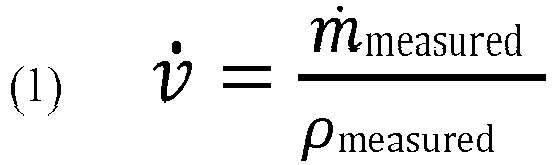
- For pure liquid fluid flows, the accuracy of the volumetric flow calculation may depend on the combined uncertainty of the mass flow and the density measurement. If there is entrained gas (i.e., Gas Void Fraction (GVF)) in the fluid flow, the above calculation may be performed to determine volumetric flow. For low GVF, the mass flow may remain almost unchanged because it is determined mainly by the mass flow of the liquid portion of the fluid flow. On the other hand, the density of the fluid flow may drop significantly due to the entrained gas therein. As a result, the indicated volumetric flow and the totalized volume of the multiphase fluid flow may be higher as compared to a pure liquid single phase fluid flow.
- In a typical oil and gas application, it may be desirable to know the volumetric flow of only a liquid portion of a multiphase fluid flow. That is, the entrained gas portion of the multiphase fluid flow may be an unwanted condition. In many instances, the entrained gas may evaporate from the fluid flow. For example, the entrained gas may evaporate in a storage tank or the like. In this manner, if the volume of the liquid in the storage tank is compared to the volume of the fluid flow as indicated by the mass flow meter, a deviation may occur.
- An indication of GVF may be a drop in the measured operating density of the fluid flow. This may be detected when the expected density of the liquid is known. For instance, the expected density of water may be calculated according to the International Association for the Properties of Water and Steam (IAPWS), and the expected density of oil can be calculated according to the American Petroleum Institute (API). For liquids, in general, the expected density may be calculated as follows:

- A reference density ρref and a reference temperature (Tref) are usually known. The linear thermal expansion coefficient a may be found in literature for most liquids, and a linear approach may be sufficient for a limited density and temperature (T) range. Based on the expected density of the fluid flow, GVF may be detected by comparing the measured operating density of the fluid flow with the expected liquid density of the fluid flow:

- As discussed above, the entrained gas portion of the fluid flow may typically be neglected. That is, only the volume of the liquid portion of the fluid flow may be of importance. In such instances, the volume of the liquid portion of the fluid flow may be calculated by replacing the measured operating density with the expected liquid density:

- By replacing the measured operating density with the expected liquid density, the volumetric flow of the liquid portion of the fluid flow is calculated by using the expected density of the liquid portion of the fluid flow:

- In addition to the detection of entrained gas in the fluid flow, it is also possible to determine the amount of entrained gas in the fluid flow. The GVF as a volume percentage is calculated by the ratio of the measured and expected densities:

- In addition to the detection of entrained gas in the fluid flow, the systems and methods described herein may be implemented to detect the presence of another denser liquid in the multiphase flow. For example:

- An example may be water in oil. In such instances, the amount of the denser liquid may be determined as a volume percentage:

- In the case of two liquids, to determine the volumetric flow of the desired component of the fluid flow, a net flow calculation may be performed:

- The aforementioned operations are directed to fluid flows comprising GVF or two different liquids. However, in certain embodiments, the fluid flow may comprise more than two liquids. In such instances, if one of the components is water, a water cut probe (for example, the
water cut probe 130 inFIG. 1 ) may be incorporated to omit the water portion. Once the water is removed from the fluid flow, the above described operations may be implemented. Water cut probes may measure the amount of water as a volume percentage, while Coriolis mass flow meters may measure the mass flow. To subtract the amount of water from the fluid flow, the density of the remaining components without water may be determined:
- The measured operating density may then be replaced by the calculated density of the fluid flow without water:

- With this new value for the measured density, the GVF check according to operation (3) or the denser liquid check according to operation (7) may be performed. For instance, if the application is a mixture of water, oil, and gas, the Coriolis mass flow and density meter may behave as if it measured only oil and gas after this operation. Thus, the three-phase flow may be reduced to a two-phase flow.
- The above determinations and calculations are for purposes of illustration and are not meant to be limiting. Other determinations, calculations, considerations, etc., may exist in other examples.
-
FIG. 2 is a flow diagram depicting anillustrative method 200 for determining a volumetric flow of a liquid portion of a multiphase fluid flow in accordance with one or more embodiments of the disclosure. In one embodiment, all or a portion of theillustrative method 200 may be performed by themass flow meter 110 inFIG. 1 . Further, all or a portion of theillustrative method 200 may be performed by any combination of themass flow meter 110, thewater cut probe 130, and aremote device 140. - The
illustrative method 200 may begin atblock 202, where an expected liquid density of a fluid flow (for example, the fluid flow 104) at an operating temperature or pressure may be determined. In some instances, the expected density of the fluid flow may be determined using known tables or equations based on one or more known properties (or expected properties) of the fluid flow. For example, the mass flow meter may retrieve the expected liquid density of a fluid flow fromdata store 120. Atblock 204, themass flow meter 210 may measure the actual density of thefluid flow 104, and themass flow meter 110 may compare the expected liquid density of the fluid flow to the measured density of the fluid flow. Atblock 206, a phase status of the fluid flow may be determined based at least in part on a comparison of the expected density to the measured density of the fluid flow. According to the invention, the phase status is determined by themass flow meter 110. Alternatively according to embodiments not part of the invention, themass flow meter 110 may transmit the measured density to theremote device 140 via thenetwork 105 and theremote device 140 may determine the phase status. According to the invention, atblock 208, if the measured density of thefluid flow 104 is lower than the expected density of thefluid flow 104, then this may be an indication of a gas-liquid multiphase fluid flow. Conversely, atblock 210, if the measured density of thefluid flow 104 is greater than the expected density of thefluid flow 104, then this may be an indication of a liquid-liquid multiphase fluid flow, wherein one of the liquids may be denser than the other. - If the measured density of the fluid flow is less than the expected density of the fluid flow, the process can proceed to block 212, where a volumetric flow of a liquid portion of the fluid flow is determined using the expected density of the fluid flow. That is, when the comparison between the measured density of the fluid flow and the expected density of the fluid flow indicates a liquid-gas multiphase fluid flow, the expected density of the fluid flow may be used to determine the volumetric flow of the liquid portion of the
fluid flow 104. According to the invention, the volumetric flow determination is made by themass flow meter 110. Alternatively as an example not part of the invention, theremote device 140 may determine the volumetric flow of the liquid portion of thefluid flow 104. In such instances, using the expected density may provide a more accurate determination of the volumetric flow of the liquid portion than using the measured density. - If the measured density of the fluid flow is greater than the expected density of the fluid flow, the process can proceed to block 214, where a volumetric flow of one of the liquid portions of the fluid flow may be determined using the measured density of the fluid flow. That is, when the comparison between the measured density of the fluid flow and the expected density of the fluid flow indicates a liquid-liquid multiphase fluid flow, the measured density of the fluid flow may be used to determine a volumetric flow of one of the liquid portions of the fluid flow, such as the less dense liquid portion of the fluid flow, in one embodiment. In one embodiment, the volumetric flow determination may be made by the
mass flow meter 110. Alternatively, theremote device 140 may determine the volumetric flow of one of the liquid portions of thefluid flow 104. -
FIG. 3 is a flow diagram depicting anillustrative method 300 for determining a volumetric flow of a liquid portion of a multiphase fluid flow, wherein one of the phases is water. In one embodiment, theillustrative method 300 may be performed by themass flow meter 110 inFIG. 1 . - The
illustrative method 300 may begin atblock 302, where it may be determined if a fluid flow (for example, the fluid flow 104) includes more than two liquids. For example, in certain embodiments, a water cut probe (for example, the water cut probe 130) may be configured to measure an amount of water in the fluid flow. In such instances, if one of the liquids is determined to be water, thewater cut probe 130 may determine the portion of the volumetric fluid flow that is water and may provide this determination to one or both of themass flow meter 110 and theremote device 140 so that the water portion of the fluid flow may be omitted when performing the operations described inFIG 2 . For example, atblock 304, a water measurement may be received from thewater cut probe 130. For example, the water measurement may be the volume of water that makes up or is included in thefluid flow 104. Based on the water measurement, atblock 306, the water portion of the fluid flow may be omitted from the fluid flow. After the water has been omitted from the fluid flow, the steps of themethod 200 inFIG. 2 may be performed atblock 308. - The operations and processes described and shown above may be carried out or performed in any suitable order as desired in various implementations. Additionally, in certain implementations, at least a portion of the operations may be carried out in parallel. Furthermore, in certain implementations, less than or more than the operations described may be performed.
- Certain aspects of the disclosure are described above with reference to block and flow diagrams of systems, methods, apparatuses, and/or computer program products according to various implementations. It will be understood that one or more blocks of the block diagrams and flow diagrams, and combinations of blocks in the block diagrams and the flow diagrams, respectively, can be implemented by computer-executable program instructions. Likewise, some blocks of the block diagrams and flow diagrams may not necessarily need to be performed in the order presented, or may not necessarily need to be performed at all, according to some implementations.
- Although specific embodiments of the disclosure have been described, numerous other modifications and alternative embodiments are within the scope of the disclosure. For example, any of the functionality described with respect to a particular device or component may be performed by another device or component. Further, while specific device characteristics have been described, embodiments of the disclosure may relate to numerous other device characteristics. Further, although embodiments have been described in language specific to structural features and/or methodological acts, it is to be understood that the disclosure is not necessarily limited to the specific features or acts described. Rather, the specific features and acts are disclosed as illustrative forms of implementing the embodiments.
- Conditional language, such as, among others, "can," "could," "might," or "may," unless specifically stated otherwise, or otherwise understood within the context as used, is generally intended to convey that certain embodiments could include, while other embodiments may not include, certain features, elements, and/or steps. Thus, such conditional language is not generally intended to imply that features, elements, and/or steps are in any way required for one or more embodiments.
Claims (5)
- A system, comprising:a pipe (102) configured to have a fluid flow (104) there through;a Coriolis mass flow meter (110) coupled to the pipe (102), wherein the Coriolis mass flow meter (110) is configured to measure a density of the fluid flow (104) in the pipe (102), the Coriolis mass flow meter (110) comprising:at least one memory (122) that stores computer-executable instructions; andat least one processor (112) configured to access the at least one memory (122), wherein the at least one processor (112) is configured to execute the computer-executable instructions to:determine an expected liquid density of the fluid flow (104) at an operating temperature;compare the expected liquid density of the fluid flow (104) to the measured density of the fluid flow (104); anddetermine, based at least in part on the expected liquid density compared to the measured density of the fluid flow (104), a phase status of the fluid flow (104),wherein when the measured density of the fluid flow (104) is less than the expected liquid density of the fluid flow (104), the phase status of the fluid flow (104) comprises a liquid/gas fluid flow (104);determine, when the measured density of the fluid flow (104) is less than the expected liquid density of the fluid flow (104), a volumetric flow of a liquid portion of the liquid/gas fluid flow (104) using the expected liquid density of the fluid flow (104); anddetermine, when the measured density of the fluid flow (104) is less than the expected density of the fluid flow (104), a volume percentage of a gas portion of the fluid flow (104) using a density ratio between the measured density of the fluid flow (104) and the expected liquid density of the fluid flow (104).
- The system of claim 1, wherein the at least one processor (112) is further configured to execute the computer-executable instructions to omit a calculated amount for water that makes up a portion of the fluid flow (104).
- The system of claim 2, further comprising a water cut probe coupled to the pipe (130).
- A method, comprising:determining, by at least one processor (112) coupled to at least one memory (122), an expected liquid density of a fluid flow (104) at an operating temperature;receiving, by the at least one processor (142), a measured density of the fluid flow (104);comparing, by the at least one processor (112), the expected liquid density of the fluid flow (104) to the measured density of the fluid flow (104); anddetermining, by the at least one processor (112) and based at least in part on the expected liquid density compared to the measured density of the fluid flow (104), a phase status of the fluid flow (104)wherein when the measured density of the fluid flow (104) is less than the expected liquid density of the fluid flow (104), the phase status of the fluid flow (104) comprises a liquid/gas fluid flow (104);determine, when the measured density of the fluid flow (104) is less than the expected liquid density of the fluid flow (104), a volumetric flow of a liquid portion of the liquid/gas fluid flow (104) using the expected liquid density of the fluid flow (104); anddetermine, when the measured density of the fluid flow (104) is less than the expected density of the fluid flow (104), a volume percentage of a gas portion of the fluid flow (104) using a density ratio between the measured density of the fluid flow (104) and the expected liquid density of the fluid flow (104).
- The method of claim 4, further comprising omitting, by the at least one processor (112), a calculated amount for water that makes up a portion of the fluid flow (104).
Applications Claiming Priority (2)
| Application Number | Priority Date | Filing Date | Title |
|---|---|---|---|
| US14/048,594 US9500576B2 (en) | 2013-10-08 | 2013-10-08 | Systems and methods for determining a volumetric flow of a liquid portion of a multiphase fluid flow |
| PCT/US2014/023066 WO2015053809A1 (en) | 2013-10-08 | 2014-03-11 | Systems and methods for determining a volumetric flow of a liquid portion of a multiphase fluid flow |
Publications (2)
| Publication Number | Publication Date |
|---|---|
| EP3055655A1 EP3055655A1 (en) | 2016-08-17 |
| EP3055655B1 true EP3055655B1 (en) | 2021-01-20 |
Family
ID=50487129
Family Applications (1)
| Application Number | Title | Priority Date | Filing Date |
|---|---|---|---|
| EP14717556.6A Not-in-force EP3055655B1 (en) | 2013-10-08 | 2014-03-11 | Systems and methods for determining a volumetric flow of a liquid portion of a multiphase fluid flow |
Country Status (3)
| Country | Link |
|---|---|
| US (1) | US9500576B2 (en) |
| EP (1) | EP3055655B1 (en) |
| WO (1) | WO2015053809A1 (en) |
Families Citing this family (1)
| Publication number | Priority date | Publication date | Assignee | Title |
|---|---|---|---|---|
| US11896064B2 (en) | 2020-12-30 | 2024-02-13 | Nike, Inc. | Interface for electroadhesive system and textile |
Citations (1)
| Publication number | Priority date | Publication date | Assignee | Title |
|---|---|---|---|---|
| US20100280757A1 (en) * | 2009-05-04 | 2010-11-04 | Agar Corporation Ltd. | Multi-Phase Fluid Measurement Apparatus and Method |
Family Cites Families (8)
| Publication number | Priority date | Publication date | Assignee | Title |
|---|---|---|---|---|
| GB2128756B (en) | 1982-10-04 | 1986-06-25 | Moore Barrett & Redwood | Measurement of two-phase or multi-phase fluid flow in pipes |
| US4876879A (en) * | 1988-08-23 | 1989-10-31 | Ruesch James R | Apparatus and methods for measuring the density of an unknown fluid using a Coriolis meter |
| US6636815B2 (en) | 2001-08-29 | 2003-10-21 | Micro Motion, Inc. | Majority component proportion determination of a fluid using a coriolis flowmeter |
| US7059199B2 (en) * | 2003-02-10 | 2006-06-13 | Invensys Systems, Inc. | Multiphase Coriolis flowmeter |
| US20080288181A1 (en) | 2005-04-26 | 2008-11-20 | Guillermo Amarfil Lucero | Multiphase flow meter and data system |
| EP1982169B1 (en) | 2006-01-11 | 2012-11-07 | Expro Meters, Inc. | Apparatus and method for measuring parameters of a multiphase fluid flow |
| JP4858829B2 (en) * | 2006-03-28 | 2012-01-18 | 横河電機株式会社 | Multi-variable mass flow transmitter system |
| CA2758779C (en) * | 2010-12-01 | 2016-01-05 | Invensys Systems, Inc. | Determining concentrations of components of a mixture |
-
2013
- 2013-10-08 US US14/048,594 patent/US9500576B2/en not_active Expired - Fee Related
-
2014
- 2014-03-11 EP EP14717556.6A patent/EP3055655B1/en not_active Not-in-force
- 2014-03-11 WO PCT/US2014/023066 patent/WO2015053809A1/en not_active Ceased
Patent Citations (1)
| Publication number | Priority date | Publication date | Assignee | Title |
|---|---|---|---|---|
| US20100280757A1 (en) * | 2009-05-04 | 2010-11-04 | Agar Corporation Ltd. | Multi-Phase Fluid Measurement Apparatus and Method |
Also Published As
| Publication number | Publication date |
|---|---|
| WO2015053809A1 (en) | 2015-04-16 |
| US9500576B2 (en) | 2016-11-22 |
| EP3055655A1 (en) | 2016-08-17 |
| US20150100252A1 (en) | 2015-04-09 |
Similar Documents
| Publication | Publication Date | Title |
|---|---|---|
| METERING | Handbook of multiphase flow metering | |
| EP3289319B1 (en) | Multiphase flow meters and related methods | |
| Talley et al. | Characterization of horizontal air–water two-phase flow in a round pipe part II: Measurement of local two-phase parameters in bubbly flow | |
| Thorn et al. | Three-phase flow measurement in the petroleum industry | |
| Magrini et al. | Liquid entrainment in annular gas/liquid flow in inclined pipes | |
| Henry et al. | Coriolis mass flow metering for three-phase flow: A case study | |
| AU2017279558B2 (en) | Nuclear magnetic flow meter and method for operation of nuclear magnet flow meters | |
| EP3062070B1 (en) | System and method for multiphase flow metering accounting for dissolved gas | |
| Vieira et al. | Experimental investigation of the effect of 90° standard elbow on horizontal gas–liquid stratified and annular flow characteristics using dual wire-mesh sensors | |
| Shaban et al. | The wire-mesh sensor as a two-phase flow meter | |
| CN103063320B (en) | The assay method of the complicated rock gas throttle temperature of a kind of High Temperature High Pressure and gas liquid ratio | |
| Tan et al. | Horizontal oil–water two-phase flow measurement with information fusion of conductance ring sensor and cone meter | |
| Medeiros et al. | Flow measurement by piezoelectric accelerometers: Application in the oil industry | |
| Vieira et al. | Experimental characterization of vertical downward two-phase annular flows using Wire-Mesh Sensor | |
| Rosa et al. | Design and performance prediction of an impedance void meter applied to the petroleum industry | |
| US20150160057A1 (en) | Systems and methods for determining mass flow measurements of fluid flows | |
| Tombs et al. | Two-phase coriolis mass flow metering with high viscosity oil | |
| Zhang et al. | Prediction of interfacial shear stress and pressure drop in vertical two-phase annular flow | |
| Ballesteros et al. | Analysis and Modeling of Liquid Holdup in Low Liquid Loading Two-Phase Flow Using Computational Fluid Dynamics and Experimental Data | |
| Rodriguez et al. | Experiments with a Wire-Mesh Sensor for stratified and dispersed oil-brine pipe flow | |
| US11099168B2 (en) | Methods and apparatus for water detection in multiphase flows | |
| Ferro et al. | New theoretical solution of stage-discharge relationship for slit weirs | |
| US9500576B2 (en) | Systems and methods for determining a volumetric flow of a liquid portion of a multiphase fluid flow | |
| Lari et al. | Error correction of a coriolis mass flow meter in two-phase flow measurment using Neuro-Fuzzy | |
| Liu et al. | Application of a mass flowmeter for allocation measurement of crude oil production |
Legal Events
| Date | Code | Title | Description |
|---|---|---|---|
| PUAI | Public reference made under article 153(3) epc to a published international application that has entered the european phase |
Free format text: ORIGINAL CODE: 0009012 |
|
| 17P | Request for examination filed |
Effective date: 20160405 |
|
| AK | Designated contracting states |
Kind code of ref document: A1 Designated state(s): AL AT BE BG CH CY CZ DE DK EE ES FI FR GB GR HR HU IE IS IT LI LT LU LV MC MK MT NL NO PL PT RO RS SE SI SK SM TR |
|
| AX | Request for extension of the european patent |
Extension state: BA ME |
|
| DAX | Request for extension of the european patent (deleted) | ||
| STAA | Information on the status of an ep patent application or granted ep patent |
Free format text: STATUS: EXAMINATION IS IN PROGRESS |
|
| 17Q | First examination report despatched |
Effective date: 20180627 |
|
| GRAP | Despatch of communication of intention to grant a patent |
Free format text: ORIGINAL CODE: EPIDOSNIGR1 |
|
| STAA | Information on the status of an ep patent application or granted ep patent |
Free format text: STATUS: GRANT OF PATENT IS INTENDED |
|
| INTG | Intention to grant announced |
Effective date: 20200226 |
|
| GRAJ | Information related to disapproval of communication of intention to grant by the applicant or resumption of examination proceedings by the epo deleted |
Free format text: ORIGINAL CODE: EPIDOSDIGR1 |
|
| STAA | Information on the status of an ep patent application or granted ep patent |
Free format text: STATUS: EXAMINATION IS IN PROGRESS |
|
| GRAS | Grant fee paid |
Free format text: ORIGINAL CODE: EPIDOSNIGR3 |
|
| STAA | Information on the status of an ep patent application or granted ep patent |
Free format text: STATUS: GRANT OF PATENT IS INTENDED |
|
| GRAP | Despatch of communication of intention to grant a patent |
Free format text: ORIGINAL CODE: EPIDOSNIGR1 |
|
| INTC | Intention to grant announced (deleted) | ||
| INTG | Intention to grant announced |
Effective date: 20200805 |
|
| GRAA | (expected) grant |
Free format text: ORIGINAL CODE: 0009210 |
|
| STAA | Information on the status of an ep patent application or granted ep patent |
Free format text: STATUS: THE PATENT HAS BEEN GRANTED |
|
| AK | Designated contracting states |
Kind code of ref document: B1 Designated state(s): AL AT BE BG CH CY CZ DE DK EE ES FI FR GB GR HR HU IE IS IT LI LT LU LV MC MK MT NL NO PL PT RO RS SE SI SK SM TR |
|
| REG | Reference to a national code |
Ref country code: GB Ref legal event code: FG4D |
|
| REG | Reference to a national code |
Ref country code: CH Ref legal event code: EP |
|
| REG | Reference to a national code |
Ref country code: AT Ref legal event code: REF Ref document number: 1356794 Country of ref document: AT Kind code of ref document: T Effective date: 20210215 |
|
| REG | Reference to a national code |
Ref country code: IE Ref legal event code: FG4D |
|
| REG | Reference to a national code |
Ref country code: DE Ref legal event code: R096 Ref document number: 602014074362 Country of ref document: DE |
|
| REG | Reference to a national code |
Ref country code: NL Ref legal event code: MP Effective date: 20210120 |
|
| REG | Reference to a national code |
Ref country code: LT Ref legal event code: MG9D |
|
| REG | Reference to a national code |
Ref country code: AT Ref legal event code: MK05 Ref document number: 1356794 Country of ref document: AT Kind code of ref document: T Effective date: 20210120 |
|
| PG25 | Lapsed in a contracting state [announced via postgrant information from national office to epo] |
Ref country code: HR Free format text: LAPSE BECAUSE OF FAILURE TO SUBMIT A TRANSLATION OF THE DESCRIPTION OR TO PAY THE FEE WITHIN THE PRESCRIBED TIME-LIMIT Effective date: 20210120 Ref country code: FI Free format text: LAPSE BECAUSE OF FAILURE TO SUBMIT A TRANSLATION OF THE DESCRIPTION OR TO PAY THE FEE WITHIN THE PRESCRIBED TIME-LIMIT Effective date: 20210120 Ref country code: GR Free format text: LAPSE BECAUSE OF FAILURE TO SUBMIT A TRANSLATION OF THE DESCRIPTION OR TO PAY THE FEE WITHIN THE PRESCRIBED TIME-LIMIT Effective date: 20210421 Ref country code: LT Free format text: LAPSE BECAUSE OF FAILURE TO SUBMIT A TRANSLATION OF THE DESCRIPTION OR TO PAY THE FEE WITHIN THE PRESCRIBED TIME-LIMIT Effective date: 20210120 Ref country code: PT Free format text: LAPSE BECAUSE OF FAILURE TO SUBMIT A TRANSLATION OF THE DESCRIPTION OR TO PAY THE FEE WITHIN THE PRESCRIBED TIME-LIMIT Effective date: 20210520 Ref country code: BG Free format text: LAPSE BECAUSE OF FAILURE TO SUBMIT A TRANSLATION OF THE DESCRIPTION OR TO PAY THE FEE WITHIN THE PRESCRIBED TIME-LIMIT Effective date: 20210420 Ref country code: NL Free format text: LAPSE BECAUSE OF FAILURE TO SUBMIT A TRANSLATION OF THE DESCRIPTION OR TO PAY THE FEE WITHIN THE PRESCRIBED TIME-LIMIT Effective date: 20210120 Ref country code: NO Free format text: LAPSE BECAUSE OF FAILURE TO SUBMIT A TRANSLATION OF THE DESCRIPTION OR TO PAY THE FEE WITHIN THE PRESCRIBED TIME-LIMIT Effective date: 20210420 |
|
| PG25 | Lapsed in a contracting state [announced via postgrant information from national office to epo] |
Ref country code: SE Free format text: LAPSE BECAUSE OF FAILURE TO SUBMIT A TRANSLATION OF THE DESCRIPTION OR TO PAY THE FEE WITHIN THE PRESCRIBED TIME-LIMIT Effective date: 20210120 Ref country code: RS Free format text: LAPSE BECAUSE OF FAILURE TO SUBMIT A TRANSLATION OF THE DESCRIPTION OR TO PAY THE FEE WITHIN THE PRESCRIBED TIME-LIMIT Effective date: 20210120 Ref country code: LV Free format text: LAPSE BECAUSE OF FAILURE TO SUBMIT A TRANSLATION OF THE DESCRIPTION OR TO PAY THE FEE WITHIN THE PRESCRIBED TIME-LIMIT Effective date: 20210120 Ref country code: PL Free format text: LAPSE BECAUSE OF FAILURE TO SUBMIT A TRANSLATION OF THE DESCRIPTION OR TO PAY THE FEE WITHIN THE PRESCRIBED TIME-LIMIT Effective date: 20210120 Ref country code: AT Free format text: LAPSE BECAUSE OF FAILURE TO SUBMIT A TRANSLATION OF THE DESCRIPTION OR TO PAY THE FEE WITHIN THE PRESCRIBED TIME-LIMIT Effective date: 20210120 |
|
| PG25 | Lapsed in a contracting state [announced via postgrant information from national office to epo] |
Ref country code: IS Free format text: LAPSE BECAUSE OF FAILURE TO SUBMIT A TRANSLATION OF THE DESCRIPTION OR TO PAY THE FEE WITHIN THE PRESCRIBED TIME-LIMIT Effective date: 20210520 |
|
| REG | Reference to a national code |
Ref country code: DE Ref legal event code: R119 Ref document number: 602014074362 Country of ref document: DE |
|
| PG25 | Lapsed in a contracting state [announced via postgrant information from national office to epo] |
Ref country code: SM Free format text: LAPSE BECAUSE OF FAILURE TO SUBMIT A TRANSLATION OF THE DESCRIPTION OR TO PAY THE FEE WITHIN THE PRESCRIBED TIME-LIMIT Effective date: 20210120 Ref country code: EE Free format text: LAPSE BECAUSE OF FAILURE TO SUBMIT A TRANSLATION OF THE DESCRIPTION OR TO PAY THE FEE WITHIN THE PRESCRIBED TIME-LIMIT Effective date: 20210120 Ref country code: CZ Free format text: LAPSE BECAUSE OF FAILURE TO SUBMIT A TRANSLATION OF THE DESCRIPTION OR TO PAY THE FEE WITHIN THE PRESCRIBED TIME-LIMIT Effective date: 20210120 Ref country code: MC Free format text: LAPSE BECAUSE OF FAILURE TO SUBMIT A TRANSLATION OF THE DESCRIPTION OR TO PAY THE FEE WITHIN THE PRESCRIBED TIME-LIMIT Effective date: 20210120 |
|
| REG | Reference to a national code |
Ref country code: CH Ref legal event code: PL |
|
| PLBE | No opposition filed within time limit |
Free format text: ORIGINAL CODE: 0009261 |
|
| STAA | Information on the status of an ep patent application or granted ep patent |
Free format text: STATUS: NO OPPOSITION FILED WITHIN TIME LIMIT |
|
| PG25 | Lapsed in a contracting state [announced via postgrant information from national office to epo] |
Ref country code: DK Free format text: LAPSE BECAUSE OF FAILURE TO SUBMIT A TRANSLATION OF THE DESCRIPTION OR TO PAY THE FEE WITHIN THE PRESCRIBED TIME-LIMIT Effective date: 20210120 Ref country code: ES Free format text: LAPSE BECAUSE OF FAILURE TO SUBMIT A TRANSLATION OF THE DESCRIPTION OR TO PAY THE FEE WITHIN THE PRESCRIBED TIME-LIMIT Effective date: 20210120 Ref country code: SK Free format text: LAPSE BECAUSE OF FAILURE TO SUBMIT A TRANSLATION OF THE DESCRIPTION OR TO PAY THE FEE WITHIN THE PRESCRIBED TIME-LIMIT Effective date: 20210120 Ref country code: RO Free format text: LAPSE BECAUSE OF FAILURE TO SUBMIT A TRANSLATION OF THE DESCRIPTION OR TO PAY THE FEE WITHIN THE PRESCRIBED TIME-LIMIT Effective date: 20210120 |
|
| REG | Reference to a national code |
Ref country code: BE Ref legal event code: MM Effective date: 20210331 |
|
| 26N | No opposition filed |
Effective date: 20211021 |
|
| GBPC | Gb: european patent ceased through non-payment of renewal fee |
Effective date: 20210420 |
|
| PG25 | Lapsed in a contracting state [announced via postgrant information from national office to epo] |
Ref country code: DE Free format text: LAPSE BECAUSE OF NON-PAYMENT OF DUE FEES Effective date: 20211001 Ref country code: IE Free format text: LAPSE BECAUSE OF NON-PAYMENT OF DUE FEES Effective date: 20210311 Ref country code: GB Free format text: LAPSE BECAUSE OF NON-PAYMENT OF DUE FEES Effective date: 20210420 Ref country code: CH Free format text: LAPSE BECAUSE OF NON-PAYMENT OF DUE FEES Effective date: 20210331 Ref country code: AL Free format text: LAPSE BECAUSE OF FAILURE TO SUBMIT A TRANSLATION OF THE DESCRIPTION OR TO PAY THE FEE WITHIN THE PRESCRIBED TIME-LIMIT Effective date: 20210120 Ref country code: LU Free format text: LAPSE BECAUSE OF NON-PAYMENT OF DUE FEES Effective date: 20210311 Ref country code: LI Free format text: LAPSE BECAUSE OF NON-PAYMENT OF DUE FEES Effective date: 20210331 |
|
| PG25 | Lapsed in a contracting state [announced via postgrant information from national office to epo] |
Ref country code: SI Free format text: LAPSE BECAUSE OF FAILURE TO SUBMIT A TRANSLATION OF THE DESCRIPTION OR TO PAY THE FEE WITHIN THE PRESCRIBED TIME-LIMIT Effective date: 20210120 |
|
| PG25 | Lapsed in a contracting state [announced via postgrant information from national office to epo] |
Ref country code: IT Free format text: LAPSE BECAUSE OF FAILURE TO SUBMIT A TRANSLATION OF THE DESCRIPTION OR TO PAY THE FEE WITHIN THE PRESCRIBED TIME-LIMIT Effective date: 20210120 |
|
| PG25 | Lapsed in a contracting state [announced via postgrant information from national office to epo] |
Ref country code: IS Free format text: LAPSE BECAUSE OF FAILURE TO SUBMIT A TRANSLATION OF THE DESCRIPTION OR TO PAY THE FEE WITHIN THE PRESCRIBED TIME-LIMIT Effective date: 20210520 |
|
| PG25 | Lapsed in a contracting state [announced via postgrant information from national office to epo] |
Ref country code: BE Free format text: LAPSE BECAUSE OF NON-PAYMENT OF DUE FEES Effective date: 20210331 |
|
| PGFP | Annual fee paid to national office [announced via postgrant information from national office to epo] |
Ref country code: FR Payment date: 20230320 Year of fee payment: 10 |
|
| PG25 | Lapsed in a contracting state [announced via postgrant information from national office to epo] |
Ref country code: HU Free format text: LAPSE BECAUSE OF FAILURE TO SUBMIT A TRANSLATION OF THE DESCRIPTION OR TO PAY THE FEE WITHIN THE PRESCRIBED TIME-LIMIT; INVALID AB INITIO Effective date: 20140311 |
|
| PG25 | Lapsed in a contracting state [announced via postgrant information from national office to epo] |
Ref country code: CY Free format text: LAPSE BECAUSE OF FAILURE TO SUBMIT A TRANSLATION OF THE DESCRIPTION OR TO PAY THE FEE WITHIN THE PRESCRIBED TIME-LIMIT Effective date: 20210120 |
|
| PG25 | Lapsed in a contracting state [announced via postgrant information from national office to epo] |
Ref country code: MK Free format text: LAPSE BECAUSE OF FAILURE TO SUBMIT A TRANSLATION OF THE DESCRIPTION OR TO PAY THE FEE WITHIN THE PRESCRIBED TIME-LIMIT Effective date: 20210120 |
|
| PG25 | Lapsed in a contracting state [announced via postgrant information from national office to epo] |
Ref country code: MT Free format text: LAPSE BECAUSE OF FAILURE TO SUBMIT A TRANSLATION OF THE DESCRIPTION OR TO PAY THE FEE WITHIN THE PRESCRIBED TIME-LIMIT Effective date: 20210120 |
|
| PG25 | Lapsed in a contracting state [announced via postgrant information from national office to epo] |
Ref country code: FR Free format text: LAPSE BECAUSE OF NON-PAYMENT OF DUE FEES Effective date: 20240331 |
|
| PG25 | Lapsed in a contracting state [announced via postgrant information from national office to epo] |
Ref country code: FR Free format text: LAPSE BECAUSE OF NON-PAYMENT OF DUE FEES Effective date: 20240331 |
|
| PG25 | Lapsed in a contracting state [announced via postgrant information from national office to epo] |
Ref country code: TR Free format text: LAPSE BECAUSE OF FAILURE TO SUBMIT A TRANSLATION OF THE DESCRIPTION OR TO PAY THE FEE WITHIN THE PRESCRIBED TIME-LIMIT Effective date: 20210120 |