EP3055643B1 - A nano-sensitive fourier-domain optical coherence tomography inspection system - Google Patents
A nano-sensitive fourier-domain optical coherence tomography inspection system Download PDFInfo
- Publication number
- EP3055643B1 EP3055643B1 EP14781556.7A EP14781556A EP3055643B1 EP 3055643 B1 EP3055643 B1 EP 3055643B1 EP 14781556 A EP14781556 A EP 14781556A EP 3055643 B1 EP3055643 B1 EP 3055643B1
- Authority
- EP
- European Patent Office
- Prior art keywords
- oct
- axial
- images
- image
- spectra
- Prior art date
- Legal status (The legal status is an assumption and is not a legal conclusion. Google has not performed a legal analysis and makes no representation as to the accuracy of the status listed.)
- Not-in-force
Links
- 238000012014 optical coherence tomography Methods 0.000 title claims description 66
- 238000007689 inspection Methods 0.000 title description 3
- 238000001228 spectrum Methods 0.000 claims description 46
- 238000000034 method Methods 0.000 claims description 25
- 230000035945 sensitivity Effects 0.000 claims description 20
- 230000005855 radiation Effects 0.000 claims description 16
- 238000003384 imaging method Methods 0.000 claims description 13
- 230000003595 spectral effect Effects 0.000 claims description 12
- 238000013507 mapping Methods 0.000 claims description 8
- 238000005286 illumination Methods 0.000 claims description 3
- 238000000354 decomposition reaction Methods 0.000 claims description 2
- 239000000523 sample Substances 0.000 description 15
- 239000002077 nanosphere Substances 0.000 description 14
- 238000013459 approach Methods 0.000 description 8
- 230000003287 optical effect Effects 0.000 description 8
- 210000001519 tissue Anatomy 0.000 description 6
- 238000002474 experimental method Methods 0.000 description 5
- 238000001727 in vivo Methods 0.000 description 5
- 239000000463 material Substances 0.000 description 5
- 230000017531 blood circulation Effects 0.000 description 4
- 238000000386 microscopy Methods 0.000 description 4
- PEDCQBHIVMGVHV-UHFFFAOYSA-N Glycerine Chemical compound OCC(O)CO PEDCQBHIVMGVHV-UHFFFAOYSA-N 0.000 description 3
- 230000004075 alteration Effects 0.000 description 3
- 210000004905 finger nail Anatomy 0.000 description 3
- 239000011521 glass Substances 0.000 description 3
- 229940028435 intralipid Drugs 0.000 description 3
- 238000000149 argon plasma sintering Methods 0.000 description 2
- 238000012512 characterization method Methods 0.000 description 2
- 238000010586 diagram Methods 0.000 description 2
- 238000006073 displacement reaction Methods 0.000 description 2
- 238000011503 in vivo imaging Methods 0.000 description 2
- 238000005259 measurement Methods 0.000 description 2
- 239000002184 metal Substances 0.000 description 2
- 239000004033 plastic Substances 0.000 description 2
- 238000012545 processing Methods 0.000 description 2
- 238000012800 visualization Methods 0.000 description 2
- 230000005653 Brownian motion process Effects 0.000 description 1
- 108010077544 Chromatin Proteins 0.000 description 1
- 229910000530 Gallium indium arsenide Inorganic materials 0.000 description 1
- 241001465754 Metazoa Species 0.000 description 1
- 206010028980 Neoplasm Diseases 0.000 description 1
- 208000037273 Pathologic Processes Diseases 0.000 description 1
- 239000004793 Polystyrene Substances 0.000 description 1
- 241001351225 Sergey Species 0.000 description 1
- 230000005540 biological transmission Effects 0.000 description 1
- 238000005537 brownian motion Methods 0.000 description 1
- 201000011510 cancer Diseases 0.000 description 1
- 210000004027 cell Anatomy 0.000 description 1
- 238000004113 cell culture Methods 0.000 description 1
- 230000004663 cell proliferation Effects 0.000 description 1
- 230000001413 cellular effect Effects 0.000 description 1
- 210000003483 chromatin Anatomy 0.000 description 1
- 238000010276 construction Methods 0.000 description 1
- 230000003247 decreasing effect Effects 0.000 description 1
- 239000003814 drug Substances 0.000 description 1
- 239000000835 fiber Substances 0.000 description 1
- 210000000245 forearm Anatomy 0.000 description 1
- 238000011835 investigation Methods 0.000 description 1
- 238000002372 labelling Methods 0.000 description 1
- 230000004089 microcirculation Effects 0.000 description 1
- 238000004377 microelectronic Methods 0.000 description 1
- 239000002086 nanomaterial Substances 0.000 description 1
- 238000012634 optical imaging Methods 0.000 description 1
- 238000012856 packing Methods 0.000 description 1
- 230000009054 pathological process Effects 0.000 description 1
- 230000010287 polarization Effects 0.000 description 1
- 229920002223 polystyrene Polymers 0.000 description 1
- 238000002360 preparation method Methods 0.000 description 1
- 230000001105 regulatory effect Effects 0.000 description 1
- 239000007787 solid Substances 0.000 description 1
- 239000000725 suspension Substances 0.000 description 1
- 230000002123 temporal effect Effects 0.000 description 1
- 238000012360 testing method Methods 0.000 description 1
- 238000003325 tomography Methods 0.000 description 1
- 210000005166 vasculature Anatomy 0.000 description 1
Images




Classifications
-
- G—PHYSICS
- G01—MEASURING; TESTING
- G01B—MEASURING LENGTH, THICKNESS OR SIMILAR LINEAR DIMENSIONS; MEASURING ANGLES; MEASURING AREAS; MEASURING IRREGULARITIES OF SURFACES OR CONTOURS
- G01B9/00—Measuring instruments characterised by the use of optical techniques
- G01B9/02—Interferometers
- G01B9/02041—Interferometers characterised by particular imaging or detection techniques
- G01B9/02044—Imaging in the frequency domain, e.g. by using a spectrometer
-
- A—HUMAN NECESSITIES
- A61—MEDICAL OR VETERINARY SCIENCE; HYGIENE
- A61B—DIAGNOSIS; SURGERY; IDENTIFICATION
- A61B5/00—Measuring for diagnostic purposes; Identification of persons
- A61B5/0059—Measuring for diagnostic purposes; Identification of persons using light, e.g. diagnosis by transillumination, diascopy, fluorescence
- A61B5/0062—Arrangements for scanning
- A61B5/0066—Optical coherence imaging
-
- A—HUMAN NECESSITIES
- A61—MEDICAL OR VETERINARY SCIENCE; HYGIENE
- A61B—DIAGNOSIS; SURGERY; IDENTIFICATION
- A61B5/00—Measuring for diagnostic purposes; Identification of persons
- A61B5/72—Signal processing specially adapted for physiological signals or for diagnostic purposes
- A61B5/7235—Details of waveform analysis
- A61B5/7253—Details of waveform analysis characterised by using transforms
- A61B5/7257—Details of waveform analysis characterised by using transforms using Fourier transforms
-
- G—PHYSICS
- G01—MEASURING; TESTING
- G01B—MEASURING LENGTH, THICKNESS OR SIMILAR LINEAR DIMENSIONS; MEASURING ANGLES; MEASURING AREAS; MEASURING IRREGULARITIES OF SURFACES OR CONTOURS
- G01B9/00—Measuring instruments characterised by the use of optical techniques
- G01B9/02—Interferometers
- G01B9/02001—Interferometers characterised by controlling or generating intrinsic radiation properties
- G01B9/02002—Interferometers characterised by controlling or generating intrinsic radiation properties using two or more frequencies
- G01B9/02004—Interferometers characterised by controlling or generating intrinsic radiation properties using two or more frequencies using frequency scans
-
- G—PHYSICS
- G01—MEASURING; TESTING
- G01B—MEASURING LENGTH, THICKNESS OR SIMILAR LINEAR DIMENSIONS; MEASURING ANGLES; MEASURING AREAS; MEASURING IRREGULARITIES OF SURFACES OR CONTOURS
- G01B9/00—Measuring instruments characterised by the use of optical techniques
- G01B9/02—Interferometers
- G01B9/02083—Interferometers characterised by particular signal processing and presentation
-
- G—PHYSICS
- G01—MEASURING; TESTING
- G01B—MEASURING LENGTH, THICKNESS OR SIMILAR LINEAR DIMENSIONS; MEASURING ANGLES; MEASURING AREAS; MEASURING IRREGULARITIES OF SURFACES OR CONTOURS
- G01B9/00—Measuring instruments characterised by the use of optical techniques
- G01B9/02—Interferometers
- G01B9/02083—Interferometers characterised by particular signal processing and presentation
- G01B9/02087—Combining two or more images of the same region
-
- G—PHYSICS
- G01—MEASURING; TESTING
- G01B—MEASURING LENGTH, THICKNESS OR SIMILAR LINEAR DIMENSIONS; MEASURING ANGLES; MEASURING AREAS; MEASURING IRREGULARITIES OF SURFACES OR CONTOURS
- G01B9/00—Measuring instruments characterised by the use of optical techniques
- G01B9/02—Interferometers
- G01B9/0209—Low-coherence interferometers
- G01B9/02091—Tomographic interferometers, e.g. based on optical coherence
-
- G—PHYSICS
- G01—MEASURING; TESTING
- G01N—INVESTIGATING OR ANALYSING MATERIALS BY DETERMINING THEIR CHEMICAL OR PHYSICAL PROPERTIES
- G01N21/00—Investigating or analysing materials by the use of optical means, i.e. using sub-millimetre waves, infrared, visible or ultraviolet light
- G01N21/17—Systems in which incident light is modified in accordance with the properties of the material investigated
- G01N21/47—Scattering, i.e. diffuse reflection
- G01N21/4795—Scattering, i.e. diffuse reflection spatially resolved investigating of object in scattering medium
-
- G—PHYSICS
- G01—MEASURING; TESTING
- G01N—INVESTIGATING OR ANALYSING MATERIALS BY DETERMINING THEIR CHEMICAL OR PHYSICAL PROPERTIES
- G01N21/00—Investigating or analysing materials by the use of optical means, i.e. using sub-millimetre waves, infrared, visible or ultraviolet light
- G01N21/17—Systems in which incident light is modified in accordance with the properties of the material investigated
- G01N2021/178—Methods for obtaining spatial resolution of the property being measured
- G01N2021/1785—Three dimensional
- G01N2021/1787—Tomographic, i.e. computerised reconstruction from projective measurements
Definitions
- the invention relates to inspection of a variety of objects, including body tissue (also in vivo ), cell cultures, materials for material science, and micro and nano electronics components, for example.
- OCT optical coherence tomography
- OCT provides non-invasive, contactless, depth resolving imaging of the object's internal structure.
- OCT facilitates cellular-level structural and functional imaging of living animal and human tissue as well as micro level imaging of different materials, but the structural sensitivity and resolution are limited to the microscale.
- phase OCT phase OCT
- vibration measurements in the ear at the nanoscale have been demonstrated, and the ability of OCT to sense nanoscale structural alteration in weakly scattering media has been discussed [1].
- the limitation to weakly scattering media generally excludes application to human tissue and to many materials of interest. describes visualization of the dominant structure (which corresponds to just one spatial frequency in depth direction) for each pixel of 2D image as a corresponding colour.
- QPM quantitative phase microscopy
- the invention is directed towards achieving improved sensitivity of 3D imaging for medical diagnostics, material science, nanofabrication, microelectronics.
- an OCT imaging method as set out in claim 1.
- the spectrum of step (a) is a full complex spectrum.
- the spectrum is formed by using quasi-collimated radiation for illumination.
- the spectrum is formed by spectral domain OCT (SDOCT).
- SDOCT spectral domain OCT
- the spectrum is formed by swept source OCT (SSOCT).
- SSOCT swept source OCT
- the step (a) includes decomposition of the spectrum of axial spatial frequencies into zones, performing reconstruction of image depth profiles for each zone, and measuring signals at each point in each reconstructed image depth profile.
- each zone corresponds to a narrow bandwidth of spatial frequencies and is considered as a single spatial frequency.
- reconstruction of corresponding images (axial Z (depth)-profiles) for each zone is performed via an inverse Fourier transform.
- step (b) the controller forms OCT 2D images and step (d) includes mapping spectra of spatial frequencies into each pixel of each of a number of said 2D images.
- the controller selects the information parameters to be calculated in step (e) according to a required application.
- the information parameters include one or more of maximum spatial frequency, dominant spatial period, centre of mass, medium spatial frequency and medium spatial period, correlation between axial spectra.
- step (b) the controller forms 2D or 3D images, and the magnitude of at least some calculated information parameters is matched to colour of each pixel of said 2D images or each voxel of said 3D OCT images.
- a sequence of OCT images in time is recorded.
- step (b) local axial spectra of step (b) are reconstructed and analysed in time.
- time dependences of calculated informative parameters for each pixel of an OCT 2D image or each voxel of a 3D OCT image are calculated and plotted.
- the radiation receiver is a 2D detector and spectral interferograms are formed simultaneously for all image points.
- the invention provides an OCT system comprising a radiation emitter, a radiation detector, an interferometer, and a controller adapted to perform the steps of a method as defined above in any embodiment.
- An OCT imaging system comprising a radiation emitter, a radiation receiver, a controller which controls the emitter and processes received radiation data according to OCT to provide an output image.
- the controller forms a spectrum of spatial frequencies along the depth direction. It calculates from the spectrum local spectra of spatial frequencies or periods along the depth direction for individual volume elements along the depth direction. It translates the local spectra of spatial frequencies or periods along the depth direction into the OCT image domain. It maps the local spectra into the volume elements to provide a sensitivity on the nano-scale whereas the volume elements are in the micro-scale.
- the controller calculates information parameters from the translated and mapped local spectra.
- the system achieves nano-scale sensitivity although the volume elements are at the micro-scale.
- the invention achieves nano-scale sensitivity OCT to structural changes, termed nano-scale sensitivity OCT ("nsOCT").
- the OCT signal is formed by light scattered from high axial spatial frequency components of the object's scattering potential which correspond to submicron structure.
- the axial Fourier spectrum of the object's scattering potential is very informative and highly sensitive to structural changes because the optical system, if the required spectral transmission is provided, does not impose any limitations on the bandwidth of translated axial spatial frequencies.
- the range of axial spatial frequencies is limited by spectral bandwidth and the resolution of spatial frequencies is limited by spectral resolution.
- conventional OCT during the inverse Fourier transform to reconstruct axial profile, the spatial information is integrated and, as a result, the resolution and sensitivity even for the best OCT systems are relatively poor.
- the local axial Fourier spectra are directly translated into each voxel of the 3D OCT image.
- submicron structure can be visualized and nanoscale structural alterations within each voxel can be detected.
- Different informative parameters can be extracted from the local profiles of the axial spatial periods to characterize structure, depending on application, and mapped into the OCT image to form a colour map.
- one of such parameters can be the maximum spatial frequency (period), which is the frequency at the maximal signal, which is directly related to the dominant size of the local structure.
- a spectral domain OCT (SD-OCT) setup such as that of Fig. 6 with low NA optics (see Methods) was used.
- the voxel size in OCT images was 12 ⁇ m x 30 ⁇ m x 30 ⁇ m
- the spatial interval to reconstruct profiles of the axial spatial periods was 4 nm
- the voxel size was 50 ⁇ m x 30 ⁇ m x 30 ⁇ m.
- the top layer contains nanospheres with 650 nm mean diameter and the bottom layer - with 670 nm mean diameter.
- These layers of nanosphere aggregates whose sizes are well beyond the resolution limit of the OCT system, are indistinguishable in the conventional OCT image Fig. 1a and, of course, the difference between them of 20 nm cannot be detected.
- the nsOCT approach shows that in most points in the bottom layer, the maximum of the profiles of the axial spatial periods was shifted to larger values (larger dominant sizes of the structure) relative to corresponding profiles in the top layer.
- Fig. 1a shows the plot of two of these selected points for the bottom and top layers, respectively.
- Fig. 1b the nsOCT image as a map of the maximal axial spatial periods (dominant axial structure sizes) is shown.
- Fig. 1c the same results are presented when the layers were flipped.
- a second experiment demonstrates the ability of nsOCT to detect nanoscale structural changes in time. Structural changes less than 30 nm within the scattering sample were made as described in Methods. We recorded 50 B-scans before and 50 B-scans after structural changes were made. Images in Fig. 2 demonstrate that there are no detectable structural changes at selected locations between second ( Fig. 2a, e ) and last ( Fig. 2b, f ) frames before, as well as between second ( Fig. 2c , g ) and last ( Fig. 2d , h ) frames after structural changes were made. The profiles of the axial spatial periods ( Fig.
- FIG. 4 an example of nsOCT application to in vivo imaging of human skin is presented.
- the time interval between images Fig. 4a , c and Fig. 4b , d was 20 ms, the same as for our model experiment ( Fig.3 ).
- the most likely reason for such structural changes is blood flow.
- the information about changes in axial spatial period profiles can be used for determination of the blood flow velocity.
- nsOCT setup was based on the SD-OCT setup shown in Fig. 6 .
- a broadband 1310 nm superluminescent diode SLD with bandwidth of 83 nm (SLD, Dense Light, Singapore) was coupled into the interferometer, via an optical coupler OC.
- the spectrometer consisted of a 50 mm focal length collimator, a 1145 lines/mm transmitting grating, an achromatic lens with a 100 mm focal length and a 14-bit, 1024 pixels InGaAs line scan camera (SU1024LDH2, Goodrich Ltd. USA) with a maximum acquisition rate of 91 kHz.
- This spectrometer setup had a spectral resolution of 0.1432 nm, which gave a maximum imaging range of ⁇ 6 mm (in air).
- the measured sensitivity of the system was ⁇ 105 dB near the zero-delay line.
- the sensitivity drop off of the system was ⁇ 20 dB at a depth range ⁇ 3 mm.
- the measured axial imaging resolution of the system was ⁇ 12 ⁇ m in air ( ⁇ 8.6 ⁇ m in human skin) and a lateral resolution was ⁇ 30 ⁇ m.
- nsOCT images were formed as maps of the maximal spatial periods for each voxel.
- the voxel size in nsOCT images was 50 ⁇ m x 30 ⁇ m x 30 ⁇ m and spatial interval to reconstruct profiles of the axial spatial periods was 4 nm.
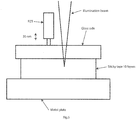
- the sample which consists of ten layers of scattering sticky tape, was placed on the solid stable basis (metal plate), as shown in Fig. 5 .
- Metal plate was rigorously fixed to the bench.
- the distance between low NA Illumination beam from OCT system and PZT tip was about 10 mm.
- Fifty OCT images (B-scans) were taken before and after 30nm shift was applied.
- the invention takes a very different approach from those described in the prior art. For example, referring to documents [10] and [11] these do not describe or suggest forming a depth resolved spectrum of spatial frequencies along the depth direction, calculating from the spectrum local spectra of spatial frequencies or periods along the depth direction for individual volume elements along the depth direction, and mapping the local spectra into the volume elements to provide a sensitivity on a scale smaller by at least one order of magnitude than that of the volume elements, and calculating information parameters from the translated and mapped local spectra.
- the invention provides extracting the local spectra of spatial frequencies in the depth direction (depth profiles) and mapping them to each voxel of the 3D reconstructed image.
- the invention achieves a very large improvement in sensitivity of OCT to structural changes. Improvement of more than 300 times has been demonstrated; using OCT system with resolution 12 ⁇ m x 30 ⁇ m x 30 ⁇ m we were able to detect the size difference between nanosphere aggregates as small as 20 nm and temporal structural changes within scattering samples less than 30 nm. The sensitivity is limited by the spectral resolution and can go far beyond what we have demonstrated here.
Landscapes
- Health & Medical Sciences (AREA)
- Physics & Mathematics (AREA)
- Life Sciences & Earth Sciences (AREA)
- General Physics & Mathematics (AREA)
- Engineering & Computer Science (AREA)
- General Health & Medical Sciences (AREA)
- Pathology (AREA)
- Signal Processing (AREA)
- Radiology & Medical Imaging (AREA)
- Nuclear Medicine, Radiotherapy & Molecular Imaging (AREA)
- Medical Informatics (AREA)
- Surgery (AREA)
- Veterinary Medicine (AREA)
- Public Health (AREA)
- Animal Behavior & Ethology (AREA)
- Molecular Biology (AREA)
- Heart & Thoracic Surgery (AREA)
- Biomedical Technology (AREA)
- Biophysics (AREA)
- Psychiatry (AREA)
- Physiology (AREA)
- Analytical Chemistry (AREA)
- Computer Vision & Pattern Recognition (AREA)
- Immunology (AREA)
- Artificial Intelligence (AREA)
- Mathematical Physics (AREA)
- Biochemistry (AREA)
- Chemical & Material Sciences (AREA)
- Optics & Photonics (AREA)
- Investigating Or Analysing Materials By Optical Means (AREA)
Description
- The invention relates to inspection of a variety of objects, including body tissue (also in vivo), cell cultures, materials for material science, and micro and nano electronics components, for example.
- Most of the fundamental pathological processes in living tissues, including cancer, exhibit changes at the nanoscale level. Recently the diffraction resolution limit has been broken and optical nanoscale microscopy has led to creation of nanoscopic medicine. However, nanoscopy largely requires labelling, is limited to superficial 2D imaging, and is not in general suitable for in vivo applications. Furthermore, it is currently believed that in many cases 2D biology does not translate into the real 3D situation.
- Optical coherence tomography (OCT) provides non-invasive, contactless, depth resolving imaging of the object's internal structure. OCT facilitates cellular-level structural and functional imaging of living animal and human tissue as well as micro level imaging of different materials, but the structural sensitivity and resolution are limited to the microscale.
- One of the effective approaches for improving performance of the optical system is the computed imaging approach which was successfully applied to optical systems, including optical tomography, wide-field characterisation of microstructure beyond the diffraction limit of the optical imaging system, and OCT. Light scattering spectroscopy (LSS) was incorporated in OCT for depth resolved nuclear morphology measurements. Spectroscopic information was extracted from OCT data and molecular imaging was realized. Correlation mapping optical coherence tomography (cmOCT) has been developed recently [8] to enable mapping of vasculature networks. Interferometric synthetic aperture microscopy (ISAM) has been developed to improve the out-of-focal plane resolution [9].
- A spectral encoding of spatial frequency (SESF) approach for quantitative characterization of the structure with nanoscale sensitivity has been developed recently ([6], [7]). The ability to map axial structural information into each pixel of 2D image with nanoscale sensitivity has been demonstrated and application of this approach to 3D microscopic imaging has been discussed. In spite of the fact that ability of existing approaches to probe structure at micro and nanoscale have been shown, the depth resolved probing of 3D structure of scattering objects with nanoscale sensitivity remains a problem.
- Recently the application of phase OCT to vibration measurements in the ear at the nanoscale has been demonstrated, and the ability of OCT to sense nanoscale structural alteration in weakly scattering media has been discussed [1]. The limitation to weakly scattering media generally excludes application to human tissue and to many materials of interest.
describes visualization of the dominant structure (which corresponds to just one spatial frequency in depth direction) for each pixel of 2D image as a corresponding colour. [11] describes a different technique, quantitative phase microscopy (QPM). This technique works for semi-transparent objects, like cells, and cannot be applied to highly scattering media, like skin in vivo. - The invention is directed towards achieving improved sensitivity of 3D imaging for medical diagnostics, material science, nanofabrication, microelectronics.
-
- 1. Yi, J. et al. "Can OCT be sensitive to nanoscale structural alterations in biological tissue?" Opt. Express 21, 9043-9059 (2013).
- 2. Cotte, Y. et al. "Marker-free phase nanoscopy. Nature Photon" 7, 113-117, (2013).
- 3. Wang, Z. et al. "Optical virtual imaging at 50 nm lateral resolution with a white light nanoscope" Nat. Commun. 2, doi:10.1038 (2011).
- 4. Guillaume, M., et al. "Experimental Demonstration of Quantitative Imaging beyond Abbe's Limit with Optical Diffraction Tomography" Phys. Rev. Lett. 102, 213905 (2009).
- 5. Huang, D. et al. "Optical Coherence Tomography" Science 254, 1178-1181 (1991).
- 6. Alexandrov, S. A., Uttam, S., Bista, R. K., Staton, K. & Liu, Y. "Spectral encoding of spatial frequency approach for characterization of nanoscale structures" Appl Phys Lett 101, 033702 (2012).
- 7. Uttam, S., Alexandrov, S. A., Bista, R. K. & Liu, Y. "Tomographic imaging via spectral encoding of spatial frequency" Opt. Express 21, 7488-7504 (2013).
- 8. [8] J. Enfield, E. Jonathan, and M. Leahy, "In vivo imaging of the microcirculation of the volar forearm using correlation mapping optical coherence tomography (cmOCT)," Biomedical Optics Express, vol. 2, pp. 1184-1193, May 1 2011.
- 9. [9] T. S. Ralston, D. L. Marks, P. S. Carney, and S. A. Boppart, "Interferometric synthetic aperture microscopy," Nature Physics, vol. 3, pp. 129-134, Feb 2007.).
- 10. Sergey, A et al: "Real-time quantitative visualisation of 3D structural information", Optics Express, 9 April 2012, vol. 20, No. 8, pages 9203-9214.
- 11. Shikhar Uttam et al: "Investigation of depth-resolved nanoscale structural changes in regulated cell proliferation and chromatin decondensation", Biomedical Optics Expess, 22 March 2013, pages 596-613.
- According to the invention, there is provided an OCT imaging method as set out in
claim 1. - In one embodiment, the spectrum of step (a) is a full complex spectrum.
- In one embodiment, the spectrum is formed by using quasi-collimated radiation for illumination.
- In one embodiment, the spectrum is formed by spectral domain OCT (SDOCT).
- In one embodiment, the spectrum is formed by swept source OCT (SSOCT).
- In one embodiment, the step (a) includes decomposition of the spectrum of axial spatial frequencies into zones, performing reconstruction of image depth profiles for each zone, and measuring signals at each point in each reconstructed image depth profile.
- In one embodiment, each zone corresponds to a narrow bandwidth of spatial frequencies and is considered as a single spatial frequency.
- In one embodiment, reconstruction of corresponding images (axial Z (depth)-profiles) for each zone is performed via an inverse Fourier transform.
- In one embodiment, in step (b) the controller forms OCT 2D images and step (d) includes mapping spectra of spatial frequencies into each pixel of each of a number of said 2D images.
- In one embodiment, the controller selects the information parameters to be calculated in step (e) according to a required application.
- In one embodiment, the information parameters include one or more of maximum spatial frequency, dominant spatial period, centre of mass, medium spatial frequency and medium spatial period, correlation between axial spectra.
- In one embodiment, in step (b) the controller forms 2D or 3D images, and the magnitude of at least some calculated information parameters is matched to colour of each pixel of said 2D images or each voxel of said 3D OCT images.
- In one embodiment, a sequence of OCT images in time is recorded.
- In one embodiment, local axial spectra of step (b) are reconstructed and analysed in time.
- In one embodiment, time dependences of calculated informative parameters for each pixel of an OCT 2D image or each voxel of a 3D OCT image are calculated and plotted.
- In one embodiment, the radiation receiver is a 2D detector and spectral interferograms are formed simultaneously for all image points.
- In another aspect, the invention provides an OCT system comprising a radiation emitter, a radiation detector, an interferometer, and a controller adapted to perform the steps of a method as defined above in any embodiment.
- The invention will be more clearly understood from the following description of some embodiments thereof, given by way of example only with reference to the accompanying drawings in which:-
-
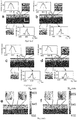
Fig. 1 shows output images for inspection by a system of the invention of two layers of nanospheres of 650 nm and 670 nm sizes, in which a and c are conventional OCT images with profiles of the axial spatial periods for selected locations, and b and d are "nsOCT" images provided by a system of the invention, and in which the lateral and depth scale bars are 500 µm; -
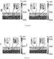
Fig. 2 shows OCT images of multilayer scattering tape with profiles of axial spatial periods and magnified portions for two selected locations (a-d) and "nsOCT" images with magnified portions for the same two selected locations (e-j) before (a, b, e, f) and after (c, d, g, h) top surface displacement of 30 nm, and in which images a, c and e, g are second frames, images b, d and f, h are fiftieth frames, images e, j are averaged images for 49 frames before e and after j top surface displacement, and lateral and depth scale bars are -
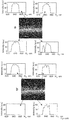
Fig. 3 shows conventional OCT (a, b) and "nsOCT" (c, d) images of Intralipid within two tubes, in which time interval between images (a, c) and (b, d) is 20 msec, and for two selected locations within the tubes and two locations outside the tubes the profiles of the axial spatial periods and magnified portions of nsOCT images are presented, and again lateral and depth scale bars are 500 µm; -
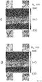
Fig. 4 shows conventional OCT (a, b) and "nsOCT" (c, d) in vivo images of a finger nail fold, in which the time interval between images (a, c) and (b, d) is 20 msec, and in which for four selected locations the profiles of the axial spatial periods and magnified portions of nsOCT images are presented, and in which lateral and depth scale bars are 500 µm; -
Fig. 5 is a diagram showing a test set-up with nanoscale tape so that nanoscale structural changes within the sample (multilayers of sticky tape) can be imaged Schematic of making nanoscale structural changes within the sample (multilayers of sticky tape); and -
Fig. 6 is a diagram of an OCT apparatus used for presented examples. - An OCT imaging system comprising a radiation emitter, a radiation receiver, a controller which controls the emitter and processes received radiation data according to OCT to provide an output image. The controller forms a spectrum of spatial frequencies along the depth direction. It calculates from the spectrum local spectra of spatial frequencies or periods along the depth direction for individual volume elements along the depth direction. It translates the local spectra of spatial frequencies or periods along the depth direction into the OCT image domain. It maps the local spectra into the volume elements to provide a sensitivity on the nano-scale whereas the volume elements are in the micro-scale. The controller calculates information parameters from the translated and mapped local spectra. Thus the system achieves nano-scale sensitivity although the volume elements are at the micro-scale.
- The invention achieves nano-scale sensitivity OCT to structural changes, termed nano-scale sensitivity OCT ("nsOCT"). The OCT signal is formed by light scattered from high axial spatial frequency components of the object's scattering potential which correspond to submicron structure. The axial Fourier spectrum of the object's scattering potential is very informative and highly sensitive to structural changes because the optical system, if the required spectral transmission is provided, does not impose any limitations on the bandwidth of translated axial spatial frequencies. The range of axial spatial frequencies is limited by spectral bandwidth and the resolution of spatial frequencies is limited by spectral resolution. In conventional OCT, during the inverse Fourier transform to reconstruct axial profile, the spatial information is integrated and, as a result, the resolution and sensitivity even for the best OCT systems are relatively poor. In the invention, in addition to reconstruction of the conventional OCT image, the local axial Fourier spectra (profiles of the axial spatial periods) are directly translated into each voxel of the 3D OCT image. As a result, submicron structure can be visualized and nanoscale structural alterations within each voxel can be detected. Different informative parameters can be extracted from the local profiles of the axial spatial periods to characterize structure, depending on application, and mapped into the OCT image to form a colour map. For example, one of such parameters can be the maximum spatial frequency (period), which is the frequency at the maximal signal, which is directly related to the dominant size of the local structure.
- The following sets out the major steps in various embodiments.
- 1. Form a conventional OCT image using Fourier domain OCT. An OCT apparatus such as illustrated n
Fig. 6 may be used, in which "SLD" is the light source, "CCD" is a charge coupled device, "PC" is polarization controller, "FC" is fibre coupler, "OC" is optical circulator, "DG" is diffraction grating, "L1 - LF" are lenses, the X and Y scanners are "X-Scan" and "Y-Scan", and the processing computer is COMP. The apparatus is conventional in the optical arrangement, however the image processing performed by the computer COMP is very different. Other types of known OCT apparatus may be used in the invention. A broad spectrum (short coherence length) or swept light source is used to access wide bandwidth of spatial frequencies. By collecting a spectral interference signal from the back scattering signal and the reference signal the depth profile of the object (A-scan) can be reconstructed. Moving in X and Y will permit 2D (B-Scan) and 3D (C-Scan) images to be formed. - 2. Rescale collected spectrum in spatial frequencies (periods).
- 3. Divide spectrum into zones.
- 4. Reconstruct corresponding images (Z (depth)-profiles for each zone, each zone corresponds to one (or some limited bandwidth) spatial frequency).
- 5. Measure signal at each Z-coordinate in each profile, reconstructed for each zone, and reconstruct spectra of spatial frequencies (local axial Fourier transforms of the object) for each point in Z-profile.
- 6. Repeat operations 2-5 for all axial scans (A-scans). Other version instead of 5, 6 could be: (5) Repeat operations 2-4 for all axial scans (A-scans); (6) Measure signal at each Z, X-coordinates (where X is lateral coordinate) in each image, reconstructed for each zone, and reconstruct spectra of spatial frequencies (local axial Fourier transforms of the object) for each point in the image.
- 7. Map spectra of spatial frequencies (or periods) into each voxel of the 3D OCT image (or into each pixel of the cross sectional 2D images and en face 2D images).
- 8. Calculate corresponding informative parameters from the spectra of spatial frequencies depending on required specific application (for example, maximum in spatial frequency or period profile, centre of mass, correlation coefficients, etc.).
- 9. Match the magnitude of the selected informative parameter to corresponding colour and form colour nsOCT image where each voxel of the 3D image (or each pixel of the cross sectional 2D images and en face 2D images) will have colour which corresponds to magnitude of the selected informative parameter (for example, maximal spatial period in the Fourier spectrum). Put corresponding colour bar in the image.
- 10. Monitor structural changes with nanoscale sensitivity in space or in time.
- It will be appreciated that this achieves nm scale sensitivity although not nm scale resolution. The spatial dimensions of the voxels are still in the µm scale, for example 50µm x 50µm x 50µm. However within such voxel sizes the system can identify dominant structures at nm scale sensitivity.
- To experimentally demonstrate the capabilities of the invention we used a spectral domain OCT (SD-OCT) setup such as that of
Fig. 6 with low NA optics (see Methods) was used. The voxel size in OCT images was 12 µm x 30 µm x 30 µm, the spatial interval to reconstruct profiles of the axial spatial periods was 4 nm and the voxel size was 50 µm x 30 µm x 30 µm. - First of all, to experimentally demonstrate the ability of our approach to probe the axial structure within a highly scattering 3D object with nano-scale sensitivity we used a sample which consists of two layers of self-assembled nanosphere aggregates of nanospheres of known sizes (see Methods). Such a sample produces a highly scattering 3D quasi-periodic structure in which the spatial periods depend on nanosphere size and packing, while also introduces some complexity and can serve as a surrogate tissue phantom. The coefficient of variance (CV) for both sizes was < 3% (see Methods), so there was some probability that nanospheres from different layers could have the same diameters.
- In
Figs. 1a, 1b the top layer contains nanospheres with 650 nm mean diameter and the bottom layer - with 670 nm mean diameter. These layers of nanosphere aggregates, whose sizes are well beyond the resolution limit of the OCT system, are indistinguishable in the conventional OCT imageFig. 1a and, of course, the difference between them of 20 nm cannot be detected. But the nsOCT approach shows that in most points in the bottom layer, the maximum of the profiles of the axial spatial periods was shifted to larger values (larger dominant sizes of the structure) relative to corresponding profiles in the top layer. -
Fig. 1a shows the plot of two of these selected points for the bottom and top layers, respectively. InFig. 1b the nsOCT image as a map of the maximal axial spatial periods (dominant axial structure sizes) is shown. One can see that for most locations the sizes of dominant axial structure in bottom layer are shifted to larger values than in the top layer and it is possible to clearly distinguish two layers with different nanostructures. InFig. 1c, d the same results are presented when the layers were flipped. These results demonstrate that the spatial difference in structural size as small as 20 nm can be detectable using the invention, nsOCT. - A second experiment demonstrates the ability of nsOCT to detect nanoscale structural changes in time. Structural changes less than 30 nm within the scattering sample were made as described in Methods. We recorded 50 B-scans before and 50 B-scans after structural changes were made. Images in
Fig. 2 demonstrate that there are no detectable structural changes at selected locations between second (Fig. 2a, e ) and last (Fig. 2b, f ) frames before, as well as between second (Fig. 2c ,g ) and last (Fig. 2d ,h ) frames after structural changes were made. The profiles of the axial spatial periods (Fig. 2a, b and c, d ) and maximal (dominant) spatial periods in nsOCT images (Fig. 2e, f andg, h ), presented as colour maps, remain unchanged. The standard deviations of the maximal spatial periods for selected points were 10-13 nm and 1.18 nm before and 10-13 nm for both locations after structural changes. - It is impossible to get any information about nanostructural changes by comparison of conventional OCT images
Fig. 2a, b and c, d ., but the structural changes can be clearly seen by comparison the profiles of the axial spatial periods, presented in OCT imagesFig. 2a, b and c, d and colour maps of dominant spatial periods in nsOCT images inFig. 2e, f andFig. 2g, h . The dominant spatial periods were decreased by 5.27 nm and 1.69 nm for two selected locations. This experiment also confirms that nanoscale structural changes smaller than 30 nm can be detected using nsOCT. - In another experiment we demonstrate the ability of nsOCT to detect relatively fast structural changes, such as blood flow, within highly scattering media. We imaged Brownian motion within Intralipid in plastic tubes through a scattering medium. The time interval between images
Fig. 3a ,c andFig. 3b ,d was 20 ms. It can be seen that there are obvious changes in the profiles of the axial spatial periods for points within the tubes, but there are no visible changes for points outside the tubes. In magnified portions of the nsOCT imagesFig. 3 c, d the structural changes within tubes are clearly seen. - Finally, in
Fig. 4 an example of nsOCT application to in vivo imaging of human skin is presented. Within living tissue there are always nanoscale structural changes, but we found that in some areas within the finger nail fold the alterations in internal structure are faster than in other areas. The time interval between imagesFig. 4a ,c andFig. 4b ,d was 20 ms, the same as for our model experiment (Fig.3 ). We can see the structural changes in the profiles of the axial spatial periods (Fig. 4 a, b ) and in the magnified portions of the nsOCT images (Fig. 4 c, d ) for points 2, 4 during this time interval, while in other areas (points 1, 3) the structure remains unchanged. The most likely reason for such structural changes is blood flow. The information about changes in axial spatial period profiles can be used for determination of the blood flow velocity. - nsOCT setup was based on the SD-OCT setup shown in
Fig. 6 . A broadband 1310 nm superluminescent diode SLD with bandwidth of 83 nm (SLD, Dense Light, Singapore) was coupled into the interferometer, via an optical coupler OC. The spectrometer consisted of a 50 mm focal length collimator, a 1145 lines/mm transmitting grating, an achromatic lens with a 100 mm focal length and a 14-bit, 1024 pixels InGaAs line scan camera (SU1024LDH2, Goodrich Ltd. USA) with a maximum acquisition rate of 91 kHz. This spectrometer setup had a spectral resolution of 0.1432 nm, which gave a maximum imaging range of ∼6 mm (in air). The sample arm consists of a pair of galvanometric driven mirrors and an objective lens with 50 mm diameter (NA=0.03) which provided a lateral resolution of ∼ 30 µm. The measured sensitivity of the system was ∼105 dB near the zero-delay line. The sensitivity drop off of the system was ∼20 dB at a depth range ± 3 mm. The measured axial imaging resolution of the system was ∼ 12 µm in air (∼8.6 µm in human skin) and a lateral resolution was ∼ 30 µm. - The OCT images were reconstructed for each small portion of axial spatial frequencies and the profiles of the axial spatial periods for each voxel were extracted from these images. nsOCT images were formed as maps of the maximal spatial periods for each voxel. The uncertainty in spatial periods determination for NA= 0.03 was less than 1 nm. The voxel size in nsOCT images was 50 µm x 30 µm x 30 µm and spatial interval to reconstruct profiles of the axial spatial periods was 4 nm.
- Nanoscale structural changes within the sample.
- The sample, which consists of ten layers of scattering sticky tape, was placed on the solid stable basis (metal plate), as shown in
Fig. 5 . Metal plate was rigorously fixed to the bench. On the top of the sample the glass slide was placed. This slide was shifted on 30 nm by PZT. So the top surface of the sample was shifted, but the bottom surface remained stable. As a result the structural changes which are smaller than 30 nm were introduced within the sample. The distance between low NA Illumination beam from OCT system and PZT tip was about 10 mm. Fifty OCT images (B-scans) were taken before and after 30nm shift was applied. - An aliquot of diluted monodispersed polystyrene nanosphere suspension (Thermo Scientific) was uniformly smeared onto the glass slide and dried, forming a thick layer of nanosphere aggregates. Two such samples were prepared, first with
nanospheres diameter 650 nm and second with nanospheres diameter 670 nm (CV ≤ 3% according to manufacturer's specification, where CV is the Coefficient of Variation, one standard deviation expressed as a percentage of the peak diameter). The complex two layers sample was made as a sandwich of two such samples of single size nanospheres with coverslip between them. - To model blood flow we used two plastic tubes with internal diameter 300 microns, filled with 9% Intralipid. The tubes were fixed on the glass slide and covered with 7 layers of scattering tape.
- For in vivo experiments we put a drop of glycerol on finger nail fold of a volunteer and captured OCT images.
- The invention takes a very different approach from those described in the prior art. For example, referring to documents [10] and [11] these do not describe or suggest forming a depth resolved spectrum of spatial frequencies along the depth direction, calculating from the spectrum local spectra of spatial frequencies or periods along the depth direction for individual volume elements along the depth direction, and mapping the local spectra into the volume elements to provide a sensitivity on a scale smaller by at least one order of magnitude than that of the volume elements, and calculating information parameters from the translated and mapped local spectra. Advantageously, the invention provides extracting the local spectra of spatial frequencies in the depth direction (depth profiles) and mapping them to each voxel of the 3D reconstructed image. It will be appreciated that the invention achieves a very large improvement in sensitivity of OCT to structural changes. Improvement of more than 300 times has been demonstrated; using OCT system with resolution 12 µm x 30 µm x 30 µm we were able to detect the size difference between nanosphere aggregates as small as 20 nm and temporal structural changes within scattering samples less than 30 nm. The sensitivity is limited by the spectral resolution and can go far beyond what we have demonstrated here.
- The invention is not limited to the embodiments described but may be varied in construction and detail as long as it falls under the scope as defined by the claims.
Claims (14)
- An OCT imaging method performed by an OCT system including a radiation emitter, a radiation receiver, an interferometer, and a controller adapted to control the emitter and to process received radiation data according to Fourier Domain OCT to provide an output image of an object, and the method comprising the steps of the controller:a(1). forming a conventional 3D Fourier Domain OCT image from axial Fourier spectra,a(2). determining a spectrum of axial spatial frequencies along a depth direction from each axial Fourier spectrum;b. calculating from each determined spectrum of step (a(2)) local axial spectra of spatial frequencies or of periods along the depth direction for individual volume element of the 3D OCT image;c. translating the local axial spectra of step (b) into the Fourier Domain OCT image domain;d. mapping said translated local axial spectra into the volume elements of the 3D OCT image to provide a sensitivity on a scale smaller by at least one order of magnitude than that of the volume elements; ande. calculating information parameters on the structure of the object from the translated and mapped local spectra of steps (c) and (d).
- A method as claimed in claim 1, wherein the spectrum of step (a) is a full complex spectrum.
- A method as claimed in any preceding claim, wherein the spectrum is formed by using quasi-collimated radiation for illumination.
- A method as claimed in any preceding claim, wherein the spectrum is formed by spectral domain OCT, SDOCT, or by swept source OCT, SSOCT.
- A method as claimed in any preceding claim, wherein the step (a) includes decomposition of the spectrum of axial spatial frequencies into zones, performing reconstruction of image depth profiles for each zone, and measuring signals at each point in each reconstructed image depth profile, and optionally each zone corresponds to a narrow bandwidth of spatial frequencies and is considered as a single spatial frequency.
- A method as claimed in claim 5, wherein reconstruction of corresponding images, which are axial z-profiles, for each zone is performed via an inverse Fourier transform.
- A method as claimed in any preceding claim, wherein in step (b) the controller forms OCT 2D images and wherein step (d) includes mapping spectra of spatial frequencies into each pixel of each of a number of said 2D images.
- A method as claimed in any preceding claim, wherein the controller selects the information parameters to be calculated in step (e) according to a required application, and the information parameters include one or more of maximum spatial frequency, dominant spatial period, centre of mass, medium spatial frequency and medium spatial period, correlation between axial spectra.
- A method as claimed in any preceding claim, wherein in step (b) the controller forms 2D or 3D images, and wherein the magnitude of at least some calculated information parameters is matched to colour of each pixel of said 2D images or each voxel of said 3D OCT images.
- A method as claimed in any preceding claim, wherein a sequence of OCT images in time is recorded.
- A method as claimed in claim 10, wherein local axial spectra of step (b) are reconstructed and analysed in time.
- A method as claimed in claims 10 or 11, wherein time dependences of calculated information parameters for each pixel of an OCT 2D image or each voxel of a 3D OCT image are calculated and plotted.
- A method as claimed in any preceding claim, wherein the radiation receiver is a 2D detector and spectral interferograms are formed simultaneously for all image points.
- An optical coherence tomography, OCT, system comprising a radiation emitter, a radiation detector, an interferometer, and a controller configured to control the emitter and to process radiation data received from the radiation by performing the steps of a method of any preceding claim.
Priority Applications (1)
| Application Number | Priority Date | Filing Date | Title |
|---|---|---|---|
| EP14781556.7A EP3055643B1 (en) | 2013-10-11 | 2014-10-08 | A nano-sensitive fourier-domain optical coherence tomography inspection system |
Applications Claiming Priority (3)
| Application Number | Priority Date | Filing Date | Title |
|---|---|---|---|
| EP13188342 | 2013-10-11 | ||
| EP14781556.7A EP3055643B1 (en) | 2013-10-11 | 2014-10-08 | A nano-sensitive fourier-domain optical coherence tomography inspection system |
| PCT/EP2014/071536 WO2015052232A1 (en) | 2013-10-11 | 2014-10-08 | A nano-sensitive fourier-domain optical coherence tomography inspection system |
Publications (2)
| Publication Number | Publication Date |
|---|---|
| EP3055643A1 EP3055643A1 (en) | 2016-08-17 |
| EP3055643B1 true EP3055643B1 (en) | 2019-07-31 |
Family
ID=49354514
Family Applications (1)
| Application Number | Title | Priority Date | Filing Date |
|---|---|---|---|
| EP14781556.7A Not-in-force EP3055643B1 (en) | 2013-10-11 | 2014-10-08 | A nano-sensitive fourier-domain optical coherence tomography inspection system |
Country Status (3)
| Country | Link |
|---|---|
| US (1) | US10012492B2 (en) |
| EP (1) | EP3055643B1 (en) |
| WO (1) | WO2015052232A1 (en) |
Cited By (1)
| Publication number | Priority date | Publication date | Assignee | Title |
|---|---|---|---|---|
| EP4242580A1 (en) | 2022-03-09 | 2023-09-13 | National University of Ireland Galway | Imaging apparatus and method |
Families Citing this family (3)
| Publication number | Priority date | Publication date | Assignee | Title |
|---|---|---|---|---|
| EP3103386B1 (en) * | 2015-06-08 | 2019-04-10 | Tomey Corporation | Blood flow velocity measuring device, program, and method |
| US12207878B2 (en) | 2020-08-05 | 2025-01-28 | LighTopTech Corp. | Apparatus and methods for three dimensional optical imaging of dynamics with reduced motion artifacts |
| CN113281305B (en) * | 2021-05-17 | 2023-04-14 | 太原理工大学 | A method and device for super-resolution microscopic imaging based on scattering medium |
Family Cites Families (4)
| Publication number | Priority date | Publication date | Assignee | Title |
|---|---|---|---|---|
| US7978346B1 (en) * | 2009-02-18 | 2011-07-12 | University Of Central Florida Research Foundation, Inc. | Methods and systems for realizing high resolution three-dimensional optical imaging |
| US9823127B2 (en) * | 2010-01-22 | 2017-11-21 | Duke University | Systems and methods for deep spectroscopic imaging of biological samples with use of an interferometer and spectrometer |
| US9332902B2 (en) * | 2012-01-20 | 2016-05-10 | Carl Zeiss Meditec, Inc. | Line-field holoscopy |
| US20130301033A1 (en) * | 2012-05-08 | 2013-11-14 | King Abdullah University Of Science And Technology | Submicron Resolution Spectral-Domain Optical Coherence Tomography |
-
2014
- 2014-10-08 EP EP14781556.7A patent/EP3055643B1/en not_active Not-in-force
- 2014-10-08 WO PCT/EP2014/071536 patent/WO2015052232A1/en not_active Ceased
- 2014-10-08 US US15/027,056 patent/US10012492B2/en active Active
Non-Patent Citations (1)
| Title |
|---|
| None * |
Cited By (2)
| Publication number | Priority date | Publication date | Assignee | Title |
|---|---|---|---|---|
| EP4242580A1 (en) | 2022-03-09 | 2023-09-13 | National University of Ireland Galway | Imaging apparatus and method |
| WO2023170243A1 (en) | 2022-03-09 | 2023-09-14 | National University Of Ireland, Galway | Imaging apparatus and method |
Also Published As
| Publication number | Publication date |
|---|---|
| US20160238370A1 (en) | 2016-08-18 |
| EP3055643A1 (en) | 2016-08-17 |
| WO2015052232A1 (en) | 2015-04-16 |
| US10012492B2 (en) | 2018-07-03 |
Similar Documents
| Publication | Publication Date | Title |
|---|---|---|
| Alexandrov et al. | Nano-sensitive optical coherence tomography | |
| Targowski et al. | Optical coherence tomography for artwork diagnostics | |
| US7633627B2 (en) | Methods, systems and computer program products for characterizing structures based on interferometric phase data | |
| De Melo et al. | Evaluation of enamel dental restoration interface<? xpp qa?> by optical coherence tomography | |
| Lee et al. | Fiber-based optical coherence tomography for biomedical imaging, sensing, and precision measurements | |
| Mauritz et al. | Imaging pharmaceutical tablets with optical coherence tomography | |
| Vairagi et al. | Common-path optical coherence tomography using the Bessel beam from negative axicon optical fiber tip | |
| US10012492B2 (en) | Nano-sensitive fourier-domain optical coherence tomography inspection system | |
| Kennedy et al. | Three-dimensional optical coherence elastography by phase-sensitive comparison of C-scans | |
| Wax et al. | Optical spectroscopy of biological cells | |
| CN102835947A (en) | Speckle relevancy-based OCT (Optical Coherence Tomography) image analyzing method | |
| Alexandrov et al. | Spatial frequency domain correlation mapping optical coherence tomography for nanoscale structural characterization | |
| Gubarkova et al. | Quantitative evaluation of atherosclerotic plaques using cross-polarization optical coherence tomography, nonlinear, and atomic force microscopy | |
| Dey et al. | Skin cancer margin detection using nanosensitive optical coherence tomography and a comparative study with confocal microscopy | |
| Das et al. | Nanoscale structure detection and monitoring of tumour growth with optical coherence tomography | |
| US20180172425A1 (en) | High definition optical coherence tomography imaging for non-invasive examination of heritage works | |
| Fischer et al. | Large field optical tomography system | |
| Reyes et al. | Dimensional metrology of lab‐on‐a‐chip internal structures: a comparison of optical coherence tomography with confocal fluorescence microscopy | |
| Liang et al. | Non-invasive imaging of subsurface paint layers with optical coherence tomography | |
| Faber et al. | Optical coherence tomography | |
| Alexandrov et al. | Nano-sensitive optical coherence tomography (nsOCT) for depth resolved characterization of 3D submicron structure | |
| Samadi | DESIGN OF A LINE FIELD OPTICAL COHERENCE TOMOGRAPHY FOR IMAGING APPLICATIONS | |
| Gomes et al. | Optical Coherence Tomography (OCT): From Basics to General Applications | |
| Zhou | Spectral 3d reconstruction based on macroscopic oct imaging | |
| Zaki et al. | Optical coherence tomography for non-invasive examination and conservation of cultural heritage objects |
Legal Events
| Date | Code | Title | Description |
|---|---|---|---|
| PUAI | Public reference made under article 153(3) epc to a published international application that has entered the european phase |
Free format text: ORIGINAL CODE: 0009012 |
|
| 17P | Request for examination filed |
Effective date: 20160510 |
|
| AK | Designated contracting states |
Kind code of ref document: A1 Designated state(s): AL AT BE BG CH CY CZ DE DK EE ES FI FR GB GR HR HU IE IS IT LI LT LU LV MC MK MT NL NO PL PT RO RS SE SI SK SM TR |
|
| AX | Request for extension of the european patent |
Extension state: BA ME |
|
| DAX | Request for extension of the european patent (deleted) | ||
| STAA | Information on the status of an ep patent application or granted ep patent |
Free format text: STATUS: EXAMINATION IS IN PROGRESS |
|
| 17Q | First examination report despatched |
Effective date: 20180914 |
|
| GRAP | Despatch of communication of intention to grant a patent |
Free format text: ORIGINAL CODE: EPIDOSNIGR1 |
|
| STAA | Information on the status of an ep patent application or granted ep patent |
Free format text: STATUS: GRANT OF PATENT IS INTENDED |
|
| INTG | Intention to grant announced |
Effective date: 20190402 |
|
| RIN1 | Information on inventor provided before grant (corrected) |
Inventor name: ALEXANDROV, SERGEY Inventor name: LEAHY, MARTIN J. Inventor name: ZAM, AZHAR Inventor name: SUBHASH, HREBESH |
|
| GRAS | Grant fee paid |
Free format text: ORIGINAL CODE: EPIDOSNIGR3 |
|
| GRAA | (expected) grant |
Free format text: ORIGINAL CODE: 0009210 |
|
| STAA | Information on the status of an ep patent application or granted ep patent |
Free format text: STATUS: THE PATENT HAS BEEN GRANTED |
|
| AK | Designated contracting states |
Kind code of ref document: B1 Designated state(s): AL AT BE BG CH CY CZ DE DK EE ES FI FR GB GR HR HU IE IS IT LI LT LU LV MC MK MT NL NO PL PT RO RS SE SI SK SM TR |
|
| REG | Reference to a national code |
Ref country code: CH Ref legal event code: EP Ref country code: GB Ref legal event code: FG4D |
|
| REG | Reference to a national code |
Ref country code: DE Ref legal event code: R096 Ref document number: 602014050921 Country of ref document: DE |
|
| REG | Reference to a national code |
Ref country code: AT Ref legal event code: REF Ref document number: 1161378 Country of ref document: AT Kind code of ref document: T Effective date: 20190815 |
|
| REG | Reference to a national code |
Ref country code: IE Ref legal event code: FG4D |
|
| REG | Reference to a national code |
Ref country code: NL Ref legal event code: MP Effective date: 20190731 |
|
| REG | Reference to a national code |
Ref country code: LT Ref legal event code: MG4D |
|
| REG | Reference to a national code |
Ref country code: AT Ref legal event code: MK05 Ref document number: 1161378 Country of ref document: AT Kind code of ref document: T Effective date: 20190731 |
|
| PG25 | Lapsed in a contracting state [announced via postgrant information from national office to epo] |
Ref country code: FI Free format text: LAPSE BECAUSE OF FAILURE TO SUBMIT A TRANSLATION OF THE DESCRIPTION OR TO PAY THE FEE WITHIN THE PRESCRIBED TIME-LIMIT Effective date: 20190731 Ref country code: LT Free format text: LAPSE BECAUSE OF FAILURE TO SUBMIT A TRANSLATION OF THE DESCRIPTION OR TO PAY THE FEE WITHIN THE PRESCRIBED TIME-LIMIT Effective date: 20190731 Ref country code: AT Free format text: LAPSE BECAUSE OF FAILURE TO SUBMIT A TRANSLATION OF THE DESCRIPTION OR TO PAY THE FEE WITHIN THE PRESCRIBED TIME-LIMIT Effective date: 20190731 Ref country code: PT Free format text: LAPSE BECAUSE OF FAILURE TO SUBMIT A TRANSLATION OF THE DESCRIPTION OR TO PAY THE FEE WITHIN THE PRESCRIBED TIME-LIMIT Effective date: 20191202 Ref country code: NO Free format text: LAPSE BECAUSE OF FAILURE TO SUBMIT A TRANSLATION OF THE DESCRIPTION OR TO PAY THE FEE WITHIN THE PRESCRIBED TIME-LIMIT Effective date: 20191031 Ref country code: SE Free format text: LAPSE BECAUSE OF FAILURE TO SUBMIT A TRANSLATION OF THE DESCRIPTION OR TO PAY THE FEE WITHIN THE PRESCRIBED TIME-LIMIT Effective date: 20190731 Ref country code: BG Free format text: LAPSE BECAUSE OF FAILURE TO SUBMIT A TRANSLATION OF THE DESCRIPTION OR TO PAY THE FEE WITHIN THE PRESCRIBED TIME-LIMIT Effective date: 20191031 Ref country code: NL Free format text: LAPSE BECAUSE OF FAILURE TO SUBMIT A TRANSLATION OF THE DESCRIPTION OR TO PAY THE FEE WITHIN THE PRESCRIBED TIME-LIMIT Effective date: 20190731 Ref country code: HR Free format text: LAPSE BECAUSE OF FAILURE TO SUBMIT A TRANSLATION OF THE DESCRIPTION OR TO PAY THE FEE WITHIN THE PRESCRIBED TIME-LIMIT Effective date: 20190731 |
|
| PG25 | Lapsed in a contracting state [announced via postgrant information from national office to epo] |
Ref country code: IS Free format text: LAPSE BECAUSE OF FAILURE TO SUBMIT A TRANSLATION OF THE DESCRIPTION OR TO PAY THE FEE WITHIN THE PRESCRIBED TIME-LIMIT Effective date: 20191130 Ref country code: RS Free format text: LAPSE BECAUSE OF FAILURE TO SUBMIT A TRANSLATION OF THE DESCRIPTION OR TO PAY THE FEE WITHIN THE PRESCRIBED TIME-LIMIT Effective date: 20190731 Ref country code: ES Free format text: LAPSE BECAUSE OF FAILURE TO SUBMIT A TRANSLATION OF THE DESCRIPTION OR TO PAY THE FEE WITHIN THE PRESCRIBED TIME-LIMIT Effective date: 20190731 Ref country code: AL Free format text: LAPSE BECAUSE OF FAILURE TO SUBMIT A TRANSLATION OF THE DESCRIPTION OR TO PAY THE FEE WITHIN THE PRESCRIBED TIME-LIMIT Effective date: 20190731 Ref country code: LV Free format text: LAPSE BECAUSE OF FAILURE TO SUBMIT A TRANSLATION OF THE DESCRIPTION OR TO PAY THE FEE WITHIN THE PRESCRIBED TIME-LIMIT Effective date: 20190731 Ref country code: GR Free format text: LAPSE BECAUSE OF FAILURE TO SUBMIT A TRANSLATION OF THE DESCRIPTION OR TO PAY THE FEE WITHIN THE PRESCRIBED TIME-LIMIT Effective date: 20191101 |
|
| PG25 | Lapsed in a contracting state [announced via postgrant information from national office to epo] |
Ref country code: TR Free format text: LAPSE BECAUSE OF FAILURE TO SUBMIT A TRANSLATION OF THE DESCRIPTION OR TO PAY THE FEE WITHIN THE PRESCRIBED TIME-LIMIT Effective date: 20190731 |
|
| PG25 | Lapsed in a contracting state [announced via postgrant information from national office to epo] |
Ref country code: PL Free format text: LAPSE BECAUSE OF FAILURE TO SUBMIT A TRANSLATION OF THE DESCRIPTION OR TO PAY THE FEE WITHIN THE PRESCRIBED TIME-LIMIT Effective date: 20190731 Ref country code: EE Free format text: LAPSE BECAUSE OF FAILURE TO SUBMIT A TRANSLATION OF THE DESCRIPTION OR TO PAY THE FEE WITHIN THE PRESCRIBED TIME-LIMIT Effective date: 20190731 Ref country code: IT Free format text: LAPSE BECAUSE OF FAILURE TO SUBMIT A TRANSLATION OF THE DESCRIPTION OR TO PAY THE FEE WITHIN THE PRESCRIBED TIME-LIMIT Effective date: 20190731 Ref country code: DK Free format text: LAPSE BECAUSE OF FAILURE TO SUBMIT A TRANSLATION OF THE DESCRIPTION OR TO PAY THE FEE WITHIN THE PRESCRIBED TIME-LIMIT Effective date: 20190731 Ref country code: RO Free format text: LAPSE BECAUSE OF FAILURE TO SUBMIT A TRANSLATION OF THE DESCRIPTION OR TO PAY THE FEE WITHIN THE PRESCRIBED TIME-LIMIT Effective date: 20190731 |
|
| PG25 | Lapsed in a contracting state [announced via postgrant information from national office to epo] |
Ref country code: CZ Free format text: LAPSE BECAUSE OF FAILURE TO SUBMIT A TRANSLATION OF THE DESCRIPTION OR TO PAY THE FEE WITHIN THE PRESCRIBED TIME-LIMIT Effective date: 20190731 Ref country code: SK Free format text: LAPSE BECAUSE OF FAILURE TO SUBMIT A TRANSLATION OF THE DESCRIPTION OR TO PAY THE FEE WITHIN THE PRESCRIBED TIME-LIMIT Effective date: 20190731 Ref country code: IS Free format text: LAPSE BECAUSE OF FAILURE TO SUBMIT A TRANSLATION OF THE DESCRIPTION OR TO PAY THE FEE WITHIN THE PRESCRIBED TIME-LIMIT Effective date: 20200224 Ref country code: MC Free format text: LAPSE BECAUSE OF FAILURE TO SUBMIT A TRANSLATION OF THE DESCRIPTION OR TO PAY THE FEE WITHIN THE PRESCRIBED TIME-LIMIT Effective date: 20190731 Ref country code: SM Free format text: LAPSE BECAUSE OF FAILURE TO SUBMIT A TRANSLATION OF THE DESCRIPTION OR TO PAY THE FEE WITHIN THE PRESCRIBED TIME-LIMIT Effective date: 20190731 |
|
| REG | Reference to a national code |
Ref country code: CH Ref legal event code: PL |
|
| REG | Reference to a national code |
Ref country code: DE Ref legal event code: R097 Ref document number: 602014050921 Country of ref document: DE |
|
| PLBE | No opposition filed within time limit |
Free format text: ORIGINAL CODE: 0009261 |
|
| STAA | Information on the status of an ep patent application or granted ep patent |
Free format text: STATUS: NO OPPOSITION FILED WITHIN TIME LIMIT |
|
| PG2D | Information on lapse in contracting state deleted |
Ref country code: IS |
|
| PG25 | Lapsed in a contracting state [announced via postgrant information from national office to epo] |
Ref country code: LI Free format text: LAPSE BECAUSE OF NON-PAYMENT OF DUE FEES Effective date: 20191031 Ref country code: LU Free format text: LAPSE BECAUSE OF NON-PAYMENT OF DUE FEES Effective date: 20191008 Ref country code: CH Free format text: LAPSE BECAUSE OF NON-PAYMENT OF DUE FEES Effective date: 20191031 Ref country code: IS Free format text: LAPSE BECAUSE OF FAILURE TO SUBMIT A TRANSLATION OF THE DESCRIPTION OR TO PAY THE FEE WITHIN THE PRESCRIBED TIME-LIMIT Effective date: 20191030 |
|
| 26N | No opposition filed |
Effective date: 20200603 |
|
| REG | Reference to a national code |
Ref country code: BE Ref legal event code: MM Effective date: 20191031 |
|
| PG25 | Lapsed in a contracting state [announced via postgrant information from national office to epo] |
Ref country code: SI Free format text: LAPSE BECAUSE OF FAILURE TO SUBMIT A TRANSLATION OF THE DESCRIPTION OR TO PAY THE FEE WITHIN THE PRESCRIBED TIME-LIMIT Effective date: 20190731 Ref country code: BE Free format text: LAPSE BECAUSE OF NON-PAYMENT OF DUE FEES Effective date: 20191031 |
|
| PG25 | Lapsed in a contracting state [announced via postgrant information from national office to epo] |
Ref country code: CY Free format text: LAPSE BECAUSE OF FAILURE TO SUBMIT A TRANSLATION OF THE DESCRIPTION OR TO PAY THE FEE WITHIN THE PRESCRIBED TIME-LIMIT Effective date: 20190731 |
|
| PG25 | Lapsed in a contracting state [announced via postgrant information from national office to epo] |
Ref country code: MT Free format text: LAPSE BECAUSE OF FAILURE TO SUBMIT A TRANSLATION OF THE DESCRIPTION OR TO PAY THE FEE WITHIN THE PRESCRIBED TIME-LIMIT Effective date: 20190731 Ref country code: HU Free format text: LAPSE BECAUSE OF FAILURE TO SUBMIT A TRANSLATION OF THE DESCRIPTION OR TO PAY THE FEE WITHIN THE PRESCRIBED TIME-LIMIT; INVALID AB INITIO Effective date: 20141008 |
|
| PG25 | Lapsed in a contracting state [announced via postgrant information from national office to epo] |
Ref country code: MK Free format text: LAPSE BECAUSE OF FAILURE TO SUBMIT A TRANSLATION OF THE DESCRIPTION OR TO PAY THE FEE WITHIN THE PRESCRIBED TIME-LIMIT Effective date: 20190731 |
|
| PGFP | Annual fee paid to national office [announced via postgrant information from national office to epo] |
Ref country code: FR Payment date: 20221020 Year of fee payment: 9 |
|
| PGFP | Annual fee paid to national office [announced via postgrant information from national office to epo] |
Ref country code: IE Payment date: 20221024 Year of fee payment: 9 Ref country code: GB Payment date: 20221020 Year of fee payment: 9 Ref country code: DE Payment date: 20221020 Year of fee payment: 9 |
|
| REG | Reference to a national code |
Ref country code: DE Ref legal event code: R119 Ref document number: 602014050921 Country of ref document: DE |
|
| GBPC | Gb: european patent ceased through non-payment of renewal fee |
Effective date: 20231008 |
|
| PG25 | Lapsed in a contracting state [announced via postgrant information from national office to epo] |
Ref country code: GB Free format text: LAPSE BECAUSE OF NON-PAYMENT OF DUE FEES Effective date: 20231008 |
|
| PG25 | Lapsed in a contracting state [announced via postgrant information from national office to epo] |
Ref country code: GB Free format text: LAPSE BECAUSE OF NON-PAYMENT OF DUE FEES Effective date: 20231008 Ref country code: FR Free format text: LAPSE BECAUSE OF NON-PAYMENT OF DUE FEES Effective date: 20231031 Ref country code: DE Free format text: LAPSE BECAUSE OF NON-PAYMENT OF DUE FEES Effective date: 20240501 |
|
| PG25 | Lapsed in a contracting state [announced via postgrant information from national office to epo] |
Ref country code: IE Free format text: LAPSE BECAUSE OF NON-PAYMENT OF DUE FEES Effective date: 20231008 |
|
| PG25 | Lapsed in a contracting state [announced via postgrant information from national office to epo] |
Ref country code: IE Free format text: LAPSE BECAUSE OF NON-PAYMENT OF DUE FEES Effective date: 20231008 |