EP3055601B1 - Composite pulsation dampener - Google Patents
Composite pulsation dampener Download PDFInfo
- Publication number
- EP3055601B1 EP3055601B1 EP14852657.7A EP14852657A EP3055601B1 EP 3055601 B1 EP3055601 B1 EP 3055601B1 EP 14852657 A EP14852657 A EP 14852657A EP 3055601 B1 EP3055601 B1 EP 3055601B1
- Authority
- EP
- European Patent Office
- Prior art keywords
- metallic
- control device
- pulsation control
- pulsation
- nozzle
- Prior art date
- Legal status (The legal status is an assumption and is not a legal conclusion. Google has not performed a legal analysis and makes no representation as to the accuracy of the status listed.)
- Active
Links
Images


Classifications
-
- F—MECHANICAL ENGINEERING; LIGHTING; HEATING; WEAPONS; BLASTING
- F16—ENGINEERING ELEMENTS AND UNITS; GENERAL MEASURES FOR PRODUCING AND MAINTAINING EFFECTIVE FUNCTIONING OF MACHINES OR INSTALLATIONS; THERMAL INSULATION IN GENERAL
- F16L—PIPES; JOINTS OR FITTINGS FOR PIPES; SUPPORTS FOR PIPES, CABLES OR PROTECTIVE TUBING; MEANS FOR THERMAL INSULATION IN GENERAL
- F16L55/00—Devices or appurtenances for use in, or in connection with, pipes or pipe systems
- F16L55/04—Devices damping pulsations or vibrations in fluids
- F16L55/041—Devices damping pulsations or vibrations in fluids specially adapted for preventing vibrations
-
- F—MECHANICAL ENGINEERING; LIGHTING; HEATING; WEAPONS; BLASTING
- F15—FLUID-PRESSURE ACTUATORS; HYDRAULICS OR PNEUMATICS IN GENERAL
- F15B—SYSTEMS ACTING BY MEANS OF FLUIDS IN GENERAL; FLUID-PRESSURE ACTUATORS, e.g. SERVOMOTORS; DETAILS OF FLUID-PRESSURE SYSTEMS, NOT OTHERWISE PROVIDED FOR
- F15B21/00—Common features of fluid actuator systems; Fluid-pressure actuator systems or details thereof, not covered by any other group of this subclass
- F15B21/008—Reduction of noise or vibration
-
- F—MECHANICAL ENGINEERING; LIGHTING; HEATING; WEAPONS; BLASTING
- F16—ENGINEERING ELEMENTS AND UNITS; GENERAL MEASURES FOR PRODUCING AND MAINTAINING EFFECTIVE FUNCTIONING OF MACHINES OR INSTALLATIONS; THERMAL INSULATION IN GENERAL
- F16L—PIPES; JOINTS OR FITTINGS FOR PIPES; SUPPORTS FOR PIPES, CABLES OR PROTECTIVE TUBING; MEANS FOR THERMAL INSULATION IN GENERAL
- F16L55/00—Devices or appurtenances for use in, or in connection with, pipes or pipe systems
- F16L55/04—Devices damping pulsations or vibrations in fluids
- F16L55/045—Devices damping pulsations or vibrations in fluids specially adapted to prevent or minimise the effects of water hammer
- F16L55/05—Buffers therefor
-
- F—MECHANICAL ENGINEERING; LIGHTING; HEATING; WEAPONS; BLASTING
- F15—FLUID-PRESSURE ACTUATORS; HYDRAULICS OR PNEUMATICS IN GENERAL
- F15B—SYSTEMS ACTING BY MEANS OF FLUIDS IN GENERAL; FLUID-PRESSURE ACTUATORS, e.g. SERVOMOTORS; DETAILS OF FLUID-PRESSURE SYSTEMS, NOT OTHERWISE PROVIDED FOR
- F15B2201/00—Accumulators
- F15B2201/30—Accumulator separating means
- F15B2201/305—Accumulator separating means without separating means
-
- F—MECHANICAL ENGINEERING; LIGHTING; HEATING; WEAPONS; BLASTING
- F15—FLUID-PRESSURE ACTUATORS; HYDRAULICS OR PNEUMATICS IN GENERAL
- F15B—SYSTEMS ACTING BY MEANS OF FLUIDS IN GENERAL; FLUID-PRESSURE ACTUATORS, e.g. SERVOMOTORS; DETAILS OF FLUID-PRESSURE SYSTEMS, NOT OTHERWISE PROVIDED FOR
- F15B2201/00—Accumulators
- F15B2201/40—Constructional details of accumulators not otherwise provided for
- F15B2201/405—Housings
- F15B2201/4053—Housings characterised by the material
Definitions
- the present application relates generally to pulsation dampeners and, more specifically, to pulsation dampeners constructed of metallic and non-metallic materials.
- Pulsation dampeners of the type described in US 2006/0228225 are used with cyclic hydraulic (e.g., reciprocating pump) systems circulating fluids to reduce the fluid pressure peaks that would otherwise accelerate deterioration of the system, the system's fluid end expendable parts, and equipment upstream or downstream from the system with each subsequent pulsation. Failure to control pressure peaks inevitably affects the operating performance and operational life of a reciprocating pump in many types of applications, including drilling, well service, oil field service, operation of industrial equipment, and mining.
- cyclic hydraulic e.g., reciprocating pump
- Pulsation dampeners are typically manufactured from steel or other metals or metal alloys due to the combination of the large vessel sizes (outer diameters greater than 20 inches/51 centimeters) and high pressures that must be contained (on the order 10,000 pounds per square inch or "psi", or about 680 atmospheres or “atm”).
- the use of steel or similar metals makes the pulsation dampeners extremely heavy, and thus cumbersome to mount or dismount on site for installation, maintenance, or replacement. Particularly in remote locations, equipment necessary to lift a pulsation dampener into or out of place is not always convenient to obtain or operate.
- US2006/060289A1 discloses a composite pressure vessel including an endcap with first and second layers.
- the first layer is a thermoplastic layer and the second layer is a thermoplastic and glass fiber composite layer.
- a method for making the vessel includes placing commingled thermoplastic and glass fibers in a heated mold to melt the thermoplastic. The molten thermoplastic and the glass fibers are molded into the endcap shape. An outer surface of the pressure vessel is finished. A pressurizable bladder with an inwardly facing surface is deflated. The outer surface of the vessel is heated to soften the thermoplastic. The pressure vessel is positioned in the bladder so that the inwardly facing surface of the bladder is adjacent to an outer surface of the pressure vessel. The bladder is pressurized to move the bladder inwardly into contact with the adjacent surfaces to each other.
- US2012/024746A1 discloses a tank which optimizes a laminating configuration of hoop layers and helical layers to enhance an efficiency of strength development by wound fibers, and a manufacturing method of the tank.
- the tank includes a liner, and a fiber reinforced-plastic layer constituted of an axial fiber layer formed by winding fibers around the outer periphery of the liner at a winding angle in a range exceeding 0 DEG and less than 30 DEG with respect to a tank axis in the center of the tank and a peripheral fiber layer formed by winding the fibers around the outer periphery of the liner at a winding angle in a range of 30 DEG or more and less than 90 DEG with respect to the tank axis, and folded fiber ends of the peripheral fiber layer in a tank axial direction draw a track which narrows from the inside toward the outside in a laminating direction of the fiber layers.
- WO94/12396A1 discloses a composite container for gas under high pressure comprising a seamless polymeric liner having a bore through one end a metal fitting bonded to the liner and penetrating the bore a plurality of metal foil layers wrapped over the liner and metal fitting, a plurality of non-metallic film layers wrapped about the metal foil layer and fitting, and an outermost layer selected from the group consisting of: a thermosetting resin matrix structure which includes a plurality of metallic fibers for reinforcement and an insulation shell.
- a process for manufacturing such containers includes winding the plurality of layers of non-metallic fibers about the metal foil layer to form a resin matrix structure, curing the resin matrix structure, and applying a thermal insulation shell about the resin matrix structure.
- the present invention is defined by a pulsation control device as defined in claim 1. Preferred and/or optional features are set out in the dependent claims.
- the pulsation control device is constructed at least partially of a composite carbon (and/or other fibers)/epoxy exostructure having an oblong cylindrical shape, (optionally with metallic portions or reinforcements), together with a non-metallic (plastic, e.g., HDPE, polymer) non-load sharing liner and metallic port nozzles.
- the nozzles may further include integral dome and piping flanges.
- a pressure drop tube may preferably extend from an opening through an exterior wall of the body into an interior space within the body. Alternatively, a different pressure drop device such as an orifice plate of one or more materials may be mounted against the outlet nozzle exterior to the body.
- FIGURES 1 through 6 discussed below, and the various embodiments used to describe the principles of the present disclosure in this patent document are by way of illustration only and should not be construed in any way to limit the scope of the disclosure. Those skilled in the art will understand that the principles of the present disclosure may be implemented in any suitably arranged pump discharge dampener that controls or partially controls pulsation amplitudes.
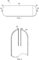
- FIGURE 1 is an external side view of a composite pulsation dampener according to an exemplary embodiment of the present disclosure.
- Pulsation dampener 100 has an intake 101 for receiving pumped fluids and an outlet 102 for discharging pump fluids under pressure. In use, the intake 101 and outlet 102 may be substantially interchangeable.
- the intake 101 and outlet 102 are formed from metallic port nozzles consisting of integral dome and piping flanges, as illustrated in FIGURE 1 . Dome-shaped end caps 103 and 104 support the intake 101 and outlet 102 and are separated by a cylindrical central portion 105 of the body of the pulsation dampener 100.
- Pulsation dampener 100 is constructed at least partially of a composite material (with possibly some metallic infrastructure or reinforcement), including a carbon (and/or other fibers)/epoxy exostructure with a liner.
- the liner is formed of a polymer material.
- the composite pulsation dampener 100 depicted has a generally oblong planform with elliptical corners, curved (cylindrical) exterior walls and rounded or hemispherical (dome-shaped) ends each including an inlet into or an outlet from the interior space within.
- Alternative embodiments not comprised by the present invention use a spheroidal shape, without the elongated central cylinder.
- vent and drain connections Not depicted in FIGURE 1 are vent and drain connections, lifting lugs, a support for mounting, inlet and outlet flange connections, the pressure drop assembly, and a nameplate, which those skilled in the art will recognize are conventionally part of a pulsation dampener.
- a composite carbon/epoxy material in the construction of a pulsation dampener is unique, and without precedent for the extremely high pressures (in the range of 10,000 psig, or about 680 atmospheres (atm)) that must be contained by the composite pulsation dampener 100 in combination with the large outer diameter (greater than 20 inches, or about 51 centimeters) of the body of the composite pulsation dampener 100 necessary for use in drilling operations.
- the system disclosed may be employed with much lower pressures, on the order of 5,000 to 7,500 psig (about 340 to 510 atm), or much higher pressures, on the order of 15,000 to 25,000 psig (about 1020 to 1700 atm) as examples.
- the composite pulsation dampener 100 is an American Society of Mechanical Engineers (ASME) Boiler and Pressure Vessel Code (BPVC) Section X (Fiber-Reinforced Plastic Pressure Vessels) Appendix 8 Class III, Type IV rated and stamped composite vessel in terms of operating pressure and outer diameter combination.
- ASME American Society of Mechanical Engineers
- BPVC Boiler and Pressure Vessel Code
- Section X Fiber-Reinforced Plastic Pressure Vessels
- the proposed structure also provides improved corrosion resistance to pumped fluids and in maritime environments.
- the composite pulsation dampener 100 enjoys a weight savings of around 75-80% as compared to metallic pulsation dampeners for a specified set of operating pressure and volume capacity parameters, and will therefore benefit from lower handling and transportation costs. As compared to the weight of a completely metallic vessel, the composite pulsation dampener 100 reduces foundation loads, shaking forces, rolling and pitching forces on flotation vessels.
- the composite pulsation dampener 100 also enjoys better corrosion resistance, and provides better protection from erosion due to the polymer liner. Moreover, composite materials have better acoustic and vibration dampening properties as compared to steel due to high co-efficient of damping and higher specific stiffness, improving the operating performance of the pulsation dampener 100 over a metallic counterpart.
- the composite material also provides low thermal expansion.
- the low number of joints and low part count provides better reliability to the composite pulsation dampener 100, which in results in a better service life. Because the manufacturing process may be automated, construction involves lower labor costs.
- FIGURE 2 is a sectional side view of portions of the composite pulsation dampener of FIGURE 1 .
- the composite pulsation dampener has an exterior wall 200 and, in the example shown, includes a pressure drop tube 201 fitted to an opening (inlet or, preferably, outlet) through the exterior wall and extending into the interior space. Vent and drain connections (not shown in FIGURES 1 or 2 ) are also provided, external of the device and possibly integrally formed with nozzles supplied for making connections to the inlet and outlet of the composite pulsation device.
- the pressure drop tube or alternative pressure drop device is not shown in FIGURES 1 or 3-6 , although the use of such devices with the embodiments of those figures is expressly contemplated.
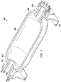
- FIGURE 3 is a cutaway perspective view of a composite pulsation dampener according to another embodiment of the disclosure.
- the pulsation dampener 300 includes an inlet (or intake) 301 and outlet 302, each formed with a disk-shaped flange at the end extending into the interior of the body and surrounding an opening through the body of the pulsation dampener 300. Exterior annular flanges are provided on each of the inlet 301 and outlet 302 for securing the respective fluid conduit to other piping.
- the body of the pulsation dampener 300 is formed of identical half structures each including dome-shaped or elliptical end structures 303 and 304 at either end of a cylindrical center portion 305.
- the embodiment of FIGURE 3 includes an integrated nozzle design of a metallic dome and piping flanges, with cylinder wall port openings for vent and drain connections. The integrated nozzle flanges provide mounting locations for both vertical and horizontal support structures and lifting lugs.
- a non-load bearing polymer liner inside the pressure vessel is chemically compatible with the drilling fluids used in the oil and gas industry, and is capable of sealing the fluids under pressures as great as 10,000 pounds per square inch (psi) (about 680 atm) (or even higher, up to 15,000 or even 20,000 psi (about 1020 to 1360 atm)), and further may be continuously operating within the cyclic pressures of the system, and at temperatures ranging from -65°F to 250°F (about -54°C to about 121°C).
- a galvanic corrosion barrier and shock isolation shear ply is located between the composite dome and metallic nozzles. This shear ply reduces the galvanic incompatibility of carbon and metals. In addition, the shear ply operates as an acoustic or shock isolation system, reducing the acoustic emissions of the pulsation control device. These improvements extend the service life of the pulsation control device.
- FIGURE 4 is an external perspective view of the composite pulsation dampener of FIGURE 3 in a vertical mount orientation.
- Mounting brackets 400 secured to the external annular flanges on the inlet 301 and the outlet 302 may be used to support the pulsation dampener 300.
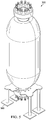
- FIGURE 5 is an external perspective view of the composite pulsation dampener of FIGURE 3 in a vertical mount orientation.
- a mounting stand 500 secured to the external annular flange on one of the inlet 301 and the outlet 302 may be used to support the pulsation dampener 300.
- FIGURE 6 is a cutaway perspective view of portions of the composite pulsation dampener of FIGURE 3 .
- the embodiment shown includes an extended inlet nozzle 602 on the inlet 601.
- the dome flange of the nozzle protrudes a distance into the pressure vessel, thus reducing the erosion effects of the polymer liner, extending the service life of the pulsation control device.
Landscapes
- Engineering & Computer Science (AREA)
- General Engineering & Computer Science (AREA)
- Mechanical Engineering (AREA)
- Chemical & Material Sciences (AREA)
- Analytical Chemistry (AREA)
- Physics & Mathematics (AREA)
- Fluid Mechanics (AREA)
- Pipe Accessories (AREA)
- Reciprocating Pumps (AREA)
- Jet Pumps And Other Pumps (AREA)
Description
- The present application relates generally to pulsation dampeners and, more specifically, to pulsation dampeners constructed of metallic and non-metallic materials.
- Pulsation dampeners of the type described in
US 2006/0228225 are used with cyclic hydraulic (e.g., reciprocating pump) systems circulating fluids to reduce the fluid pressure peaks that would otherwise accelerate deterioration of the system, the system's fluid end expendable parts, and equipment upstream or downstream from the system with each subsequent pulsation. Failure to control pressure peaks inevitably affects the operating performance and operational life of a reciprocating pump in many types of applications, including drilling, well service, oil field service, operation of industrial equipment, and mining. - Pulsation dampeners are typically manufactured from steel or other metals or metal alloys due to the combination of the large vessel sizes (outer diameters greater than 20 inches/51 centimeters) and high pressures that must be contained (on the order 10,000 pounds per square inch or "psi", or about 680 atmospheres or "atm"). However, the use of steel or similar metals makes the pulsation dampeners extremely heavy, and thus cumbersome to mount or dismount on site for installation, maintenance, or replacement. Particularly in remote locations, equipment necessary to lift a pulsation dampener into or out of place is not always convenient to obtain or operate.
US2006/060289A1 discloses a composite pressure vessel including an endcap with first and second layers. The first layer is a thermoplastic layer and the second layer is a thermoplastic and glass fiber composite layer. A method for making the vessel includes placing commingled thermoplastic and glass fibers in a heated mold to melt the thermoplastic. The molten thermoplastic and the glass fibers are molded into the endcap shape. An outer surface of the pressure vessel is finished. A pressurizable bladder with an inwardly facing surface is deflated. The outer surface of the vessel is heated to soften the thermoplastic. The pressure vessel is positioned in the bladder so that the inwardly facing surface of the bladder is adjacent to an outer surface of the pressure vessel. The bladder is pressurized to move the bladder inwardly into contact with the adjacent surfaces to each other.
US2012/024746A1 discloses a tank which optimizes a laminating configuration of hoop layers and helical layers to enhance an efficiency of strength development by wound fibers, and a manufacturing method of the tank. The tank includes a liner, and a fiber reinforced-plastic layer constituted of an axial fiber layer formed by winding fibers around the outer periphery of the liner at a winding angle in a range exceeding 0 DEG and less than 30 DEG with respect to a tank axis in the center of the tank and a peripheral fiber layer formed by winding the fibers around the outer periphery of the liner at a winding angle in a range of 30 DEG or more and less than 90 DEG with respect to the tank axis, and folded fiber ends of the peripheral fiber layer in a tank axial direction draw a track which narrows from the inside toward the outside in a laminating direction of the fiber layers. The folded fiber ends formed outwardly in the laminating direction of the fiber layers are in principle positioned closer to the center of the tank than the folded fiber ends of the peripheral fiber layer in the tank axial direction formed inwardly in the laminating direction.WO94/12396A1
There is, therefore, a need in the art for an improved pump dampener that may be handled with greater ease. - The present invention is defined by a pulsation control device as defined in claim 1. Preferred and/or optional features are set out in the dependent claims. The pulsation control device is constructed at least partially of a composite carbon (and/or other fibers)/epoxy exostructure having an oblong cylindrical shape, (optionally with metallic portions or reinforcements), together with a non-metallic (plastic, e.g., HDPE, polymer) non-load sharing liner and metallic port nozzles. The nozzles may further include integral dome and piping flanges. A pressure drop tube may preferably extend from an opening through an exterior wall of the body into an interior space within the body. Alternatively, a different pressure drop device such as an orifice plate of one or more materials may be mounted against the outlet nozzle exterior to the body.
- Before undertaking the DETAILED DESCRIPTION below, it may be advantageous to set forth definitions of certain words and phrases used throughout this patent document: the terms "include" and "comprise," as well as derivatives thereof, mean inclusion without limitation; the term "or," is inclusive, meaning and/or; and the phrases "associated with" and "associated therewith," as well as derivatives thereof, may mean to include, be included within, interconnect with, contain, be contained within, connect to or with, couple to or with, be communicable with, cooperate with, interleave, juxtapose, be proximate to, be bound to or with, have, have a property of, or the like.
- For a more complete understanding of the present disclosure and its advantages, reference is now made to the following description taken in conjunction with the accompanying drawings, in which like reference numerals represent like parts:
-
FIGURE 1 is an external side view of a composite pulsation dampener according to an exemplary embodiment of the present disclosure; -
FIGURE 2 is a sectional side view of portions of the composite pulsation dampener ofFIGURE 1 ; -
FIGURE 3 is a cutaway perspective view of a composite pulsation dampener according to another embodiment of the disclosure; -
FIGURE 4 is an external perspective view of the composite pulsation dampener ofFIGURE 3 in a vertical mount orientation. -
FIGURE 5 is an external perspective view of the composite pulsation dampener ofFIGURE 3 in a vertical mount orientation; and -
FIGURE 6 is a cutaway perspective view of portions of the composite pulsation dampener ofFIGURE 3 . -
FIGURES 1 through 6 , discussed below, and the various embodiments used to describe the principles of the present disclosure in this patent document are by way of illustration only and should not be construed in any way to limit the scope of the disclosure. Those skilled in the art will understand that the principles of the present disclosure may be implemented in any suitably arranged pump discharge dampener that controls or partially controls pulsation amplitudes. -
FIGURE 1 is an external side view of a composite pulsation dampener according to an exemplary embodiment of the present disclosure.Pulsation dampener 100 has anintake 101 for receiving pumped fluids and anoutlet 102 for discharging pump fluids under pressure. In use, theintake 101 andoutlet 102 may be substantially interchangeable. Theintake 101 andoutlet 102 are formed from metallic port nozzles consisting of integral dome and piping flanges, as illustrated inFIGURE 1 . Dome-shaped end caps intake 101 andoutlet 102 and are separated by a cylindricalcentral portion 105 of the body of thepulsation dampener 100. -
Pulsation dampener 100 is constructed at least partially of a composite material (with possibly some metallic infrastructure or reinforcement), including a carbon (and/or other fibers)/epoxy exostructure with a liner. The liner is formed of a polymer material. Thecomposite pulsation dampener 100 depicted has a generally oblong planform with elliptical corners, curved (cylindrical) exterior walls and rounded or hemispherical (dome-shaped) ends each including an inlet into or an outlet from the interior space within. Alternative embodiments not comprised by the present invention use a spheroidal shape, without the elongated central cylinder. Not depicted inFIGURE 1 are vent and drain connections, lifting lugs, a support for mounting, inlet and outlet flange connections, the pressure drop assembly, and a nameplate, which those skilled in the art will recognize are conventionally part of a pulsation dampener. - The use of a composite carbon/epoxy material, in the construction of a pulsation dampener is unique, and without precedent for the extremely high pressures (in the range of 10,000 psig, or about 680 atmospheres (atm)) that must be contained by the composite pulsation dampener 100 in combination with the large outer diameter (greater than 20 inches, or about 51 centimeters) of the body of the composite pulsation dampener 100 necessary for use in drilling operations. Of course, the system disclosed may be employed with much lower pressures, on the order of 5,000 to 7,500 psig (about 340 to 510 atm), or much higher pressures, on the order of 15,000 to 25,000 psig (about 1020 to 1700 atm) as examples. In addition, the
composite pulsation dampener 100 is an American Society of Mechanical Engineers (ASME) Boiler and Pressure Vessel Code (BPVC) Section X (Fiber-Reinforced Plastic Pressure Vessels) Appendix 8 Class III, Type IV rated and stamped composite vessel in terms of operating pressure and outer diameter combination. - The proposed structure also provides improved corrosion resistance to pumped fluids and in maritime environments.
- The
composite pulsation dampener 100 enjoys a weight savings of around 75-80% as compared to metallic pulsation dampeners for a specified set of operating pressure and volume capacity parameters, and will therefore benefit from lower handling and transportation costs. As compared to the weight of a completely metallic vessel, the composite pulsation dampener 100 reduces foundation loads, shaking forces, rolling and pitching forces on flotation vessels. - The
composite pulsation dampener 100 also enjoys better corrosion resistance, and provides better protection from erosion due to the polymer liner. Moreover, composite materials have better acoustic and vibration dampening properties as compared to steel due to high co-efficient of damping and higher specific stiffness, improving the operating performance of the pulsation dampener 100 over a metallic counterpart. - The composite material also provides low thermal expansion. The low number of joints and low part count provides better reliability to the
composite pulsation dampener 100, which in results in a better service life. Because the manufacturing process may be automated, construction involves lower labor costs. -
FIGURE 2 is a sectional side view of portions of the composite pulsation dampener ofFIGURE 1 . The composite pulsation dampener has anexterior wall 200 and, in the example shown, includes apressure drop tube 201 fitted to an opening (inlet or, preferably, outlet) through the exterior wall and extending into the interior space. Vent and drain connections (not shown inFIGURES 1 or 2 ) are also provided, external of the device and possibly integrally formed with nozzles supplied for making connections to the inlet and outlet of the composite pulsation device. For simplicity and clarity, the pressure drop tube or alternative pressure drop device is not shown inFIGURES 1 or3-6 , although the use of such devices with the embodiments of those figures is expressly contemplated. -
FIGURE 3 is a cutaway perspective view of a composite pulsation dampener according to another embodiment of the disclosure. Thepulsation dampener 300 includes an inlet (or intake) 301 andoutlet 302, each formed with a disk-shaped flange at the end extending into the interior of the body and surrounding an opening through the body of thepulsation dampener 300. Exterior annular flanges are provided on each of theinlet 301 andoutlet 302 for securing the respective fluid conduit to other piping. The body of thepulsation dampener 300 is formed of identical half structures each including dome-shaped orelliptical end structures cylindrical center portion 305. The embodiment ofFIGURE 3 includes an integrated nozzle design of a metallic dome and piping flanges, with cylinder wall port openings for vent and drain connections. The integrated nozzle flanges provide mounting locations for both vertical and horizontal support structures and lifting lugs. - The materials of the body of the
pulsation dampener 300 are the same as those described above in connection with the embodiment ofFIGURE 1 . A non-load bearing polymer liner inside the pressure vessel is chemically compatible with the drilling fluids used in the oil and gas industry, and is capable of sealing the fluids under pressures as great as 10,000 pounds per square inch (psi) (about 680 atm) (or even higher, up to 15,000 or even 20,000 psi (about 1020 to 1360 atm)), and further may be continuously operating within the cyclic pressures of the system, and at temperatures ranging from -65°F to 250°F (about -54°C to about 121°C). - A galvanic corrosion barrier and shock isolation shear ply is located between the composite dome and metallic nozzles. This shear ply reduces the galvanic incompatibility of carbon and metals. In addition, the shear ply operates as an acoustic or shock isolation system, reducing the acoustic emissions of the pulsation control device. These improvements extend the service life of the pulsation control device.
-
FIGURE 4 is an external perspective view of the composite pulsation dampener ofFIGURE 3 in a vertical mount orientation. Mountingbrackets 400 secured to the external annular flanges on theinlet 301 and theoutlet 302 may be used to support thepulsation dampener 300. -
FIGURE 5 is an external perspective view of the composite pulsation dampener ofFIGURE 3 in a vertical mount orientation. A mountingstand 500 secured to the external annular flange on one of theinlet 301 and theoutlet 302 may be used to support thepulsation dampener 300. -
FIGURE 6 is a cutaway perspective view of portions of the composite pulsation dampener ofFIGURE 3 . The embodiment shown includes anextended inlet nozzle 602 on theinlet 601. The dome flange of the nozzle protrudes a distance into the pressure vessel, thus reducing the erosion effects of the polymer liner, extending the service life of the pulsation control device. - Although the present disclosure has been described with exemplary embodiments, various changes and modifications may be suggested to one skilled in the art. It is intended that the present disclosure encompass such changes and modifications as fall within the scope of the appended claims.
Claims (10)
- A pulsation control device (100, 300), comprising:a body constructed of a composite, non-metallic carbon fiber and epoxy material having a polymer liner, the body forming an annular cylinder with dome-shaped ends (103,104,303,304) and sealing fluids under pressure inside, the body formed with identical half structures each half structure including half a dome-shaped or half elliptical end structure (101, 104, 303, 304) at either end of half a cylindrical center portion (105, 305); anda metallic inlet nozzle (101, 301, 601) and a metallic outlet nozzle (102, 302) each within an opening in one of the dome-shaped or elliptical ends (103, 104, 302, 304) of the body, the metallic inlet nozzle (101, 301, 601) and the metallic outlet nozzle (102, 302) permitting fluid flow into and out of the body.
- The pulsation control device according to Claim 1, further comprising:
a galvanic corrosion barrier and a shock isolation shear ply located between portions of the dome-shaped ends (103, 104, 303, 304) of the body and the metallic inlet nozzle (101, 301, 601) and the metallic outlet nozzle (102, 302). - The pulsation control device according to Claim 1 or Claim 2, wherein the polymer is chemically compatible with oil and gas industry drilling fluids.
- The pulsation control device according to any preceding Claim, further comprising:
a pressure drop tube (201) extending from an opening through an exterior wall of the body into an interior space within the body. - The pulsation control device according to any preceding Claim, further comprising:
a pressure drop structure affixed to one of the metallic inlet nozzle (101, 301, 601) and the metallic outlet nozzle (102, 302). - The pulsation control device according to any preceding Claim, wherein the metallic inlet nozzle (101, 301, 601) and the metallic outlet nozzle (102, 302) each include integrated nozzle flanges that provide mounting locations for both support structures and lifting lugs.
- The pulsation control device according to any preceding Claim, wherein the pulsation control device is mounted horizontally or vertically.
- The pulsation control device according to claim 6 as dependent on claim 3 as dependent on claim 2, wherein each of the metallic inlet nozzle (101, 301, 601) and the metallic outlet nozzle (102, 302) includes a disk-shaped flange at an end interior to the body, wherein the galvanic corrosion barrier and the shock isolation shear ply is disposed between the disk-shaped flanges and the portions of the dome-shaped ends (103, 104, 303, 304) of the body.
- The pulsation control device according to claim 6 as dependent on claim 3, wherein the metallic inlet nozzle (601) includes an extension (602) extending into an interior of the body.
- The pulsation control device according to any preceding Claim, wherein the body is formed using fiber/polymer composite materials reducing acoustic emissions and providing vibration dampening of pulsation pressure surges.
Applications Claiming Priority (2)
| Application Number | Priority Date | Filing Date | Title |
|---|---|---|---|
| US201361888402P | 2013-10-08 | 2013-10-08 | |
| PCT/US2014/059758 WO2015054425A1 (en) | 2013-10-08 | 2014-10-08 | Composite pulsation dampener |
Publications (3)
| Publication Number | Publication Date |
|---|---|
| EP3055601A1 EP3055601A1 (en) | 2016-08-17 |
| EP3055601A4 EP3055601A4 (en) | 2017-10-18 |
| EP3055601B1 true EP3055601B1 (en) | 2020-03-04 |
Family
ID=52775989
Family Applications (1)
| Application Number | Title | Priority Date | Filing Date |
|---|---|---|---|
| EP14852657.7A Active EP3055601B1 (en) | 2013-10-08 | 2014-10-08 | Composite pulsation dampener |
Country Status (4)
| Country | Link |
|---|---|
| US (1) | US9695970B2 (en) |
| EP (1) | EP3055601B1 (en) |
| BR (1) | BR112016007931B1 (en) |
| WO (1) | WO2015054425A1 (en) |
Families Citing this family (5)
| Publication number | Priority date | Publication date | Assignee | Title |
|---|---|---|---|---|
| EP3538808B1 (en) | 2016-11-09 | 2023-03-08 | Performance Pulsation Control, Inc. | Combination gas pulsation dampener, cross and strainer |
| EA202100010A1 (en) | 2018-06-25 | 2021-05-31 | Перформанс Пулсатион Контрол, Инк | RETAINING CASE FOR HIGH PRE-CHARGER CARTRIDGE |
| WO2020227423A1 (en) * | 2019-05-06 | 2020-11-12 | Performance Pulsation Control, Inc. | Mini-dampeners at pump combined with system pulsation dampener |
| MX2021013600A (en) * | 2019-05-06 | 2022-01-18 | Performance Pulsation Control Inc | System pulsation dampener device(s) substituting for pulsation dampeners utilizing compression material therein. |
| CA3198622A1 (en) | 2020-10-12 | 2022-04-21 | Performance Pulsation Control, Inc. | Surface equipment protection from borehole pulsation energies |
Citations (1)
| Publication number | Priority date | Publication date | Assignee | Title |
|---|---|---|---|---|
| WO1994012396A1 (en) * | 1992-11-20 | 1994-06-09 | Ngv Systems, Inc. | Compressed gas container and method of manufacture |
Family Cites Families (31)
| Publication number | Priority date | Publication date | Assignee | Title |
|---|---|---|---|---|
| US2097985A (en) * | 1936-09-28 | 1937-11-02 | Maryott Anson Abram | Fountain spraying device |
| US2875788A (en) * | 1956-02-27 | 1959-03-03 | Westinghouse Air Brake Co | Pulsation dampener device |
| US3508677A (en) * | 1968-08-20 | 1970-04-28 | Whittaker Corp | Vessel for storing high-pressure gases |
| US3815773A (en) * | 1971-05-17 | 1974-06-11 | Brunswick Corp | Cyclic pressure vessel |
| CH558746A (en) * | 1973-05-28 | 1975-02-14 | Basler Stueckfaerberei Ag | CYLINDRICAL RESERVOIR MADE OF FIBER REINFORCED PLASTIC AND THE METHOD FOR MANUFACTURING THE SAME. |
| US4265274A (en) * | 1979-09-04 | 1981-05-05 | Greer Hydraulics, Incorporated | Pulsation dampener for low output systems |
| US4603711A (en) * | 1980-02-27 | 1986-08-05 | Hydro Rene Leduc | Prestressed hydraulic accumulator |
| US4585400A (en) | 1982-07-26 | 1986-04-29 | Miller James D | Apparatus for dampening pump pressure pulsations |
| IT1185613B (en) * | 1985-05-30 | 1987-11-12 | Magnaghi Cleodinamica Spa | GAS-OIL PRESSURE ACCUMULATOR WITH COMPOSITE MATERIAL STRUCTURE FOR AIRCRAFT HYDRAULIC CIRCUITS |
| US4982856A (en) * | 1989-06-23 | 1991-01-08 | General Electric Company | High temperature, high pressure continuous random glass fiber reinforced thermoplastic fluid vessel and method of making |
| US5129427A (en) * | 1991-04-17 | 1992-07-14 | The Aro Corporation | Pulsation damper for a pumped liquid system |
| US5253778A (en) * | 1992-01-28 | 1993-10-19 | Edo Canada Ltd. | Fluid pressure vessel boss-liner attachment system |
| EP0693167A1 (en) * | 1993-04-07 | 1996-01-24 | EDO CANADA Ltd. | Fluid pressure vessel boss-liner attachment system with liner/exterior mechanism direct coupling |
| US5499739A (en) * | 1994-01-19 | 1996-03-19 | Atlantic Research Corporation | Thermoplastic liner for and method of overwrapping high pressure vessels |
| US5518141A (en) * | 1994-01-24 | 1996-05-21 | Newhouse; Norman L. | Pressure vessel with system to prevent liner separation |
| US5860452A (en) | 1998-04-02 | 1999-01-19 | Ellis; Harrell P. | Pulsation dampener |
| CA2464664C (en) * | 2001-10-12 | 2012-02-07 | Polymer & Steel Technologies Holding Company, L.L.C. | Composite pressure vessel assembly and method |
| US20040108319A1 (en) * | 2002-12-09 | 2004-06-10 | Bettinger David S. | Composite Tank Stabilizer |
| US7108016B2 (en) * | 2004-03-08 | 2006-09-19 | The United States Of America As Represented By The Administrator Of The Environmental Protection Agency | Lightweight low permeation piston-in-sleeve accumulator |
| US7013925B1 (en) * | 2004-11-18 | 2006-03-21 | Shurflo, Llc | Accumulator tank assembly and method |
| US7451662B2 (en) * | 2005-02-25 | 2008-11-18 | Endress + Hauser Flowtec Ag | Vibration type measurement transducer |
| WO2006099622A2 (en) | 2005-03-17 | 2006-09-21 | Rogers John T | Reciprocating pump performance prediction |
| US7493916B2 (en) * | 2005-12-12 | 2009-02-24 | Bosch Rexroth Corporation | Pressure vessel with accumulator isolation device |
| DE102006004120A1 (en) * | 2006-01-25 | 2007-07-26 | Hydac Technology Gmbh | Hydraulic accumulator, has coaxially abutting plastics casings, with poppet valve for controlling supply and extraction of medium |
| DE102006006902B4 (en) * | 2006-02-09 | 2008-02-21 | Gräfenthaler Kunststofftechnik GmbH | Plastic pressure vessel and process for its manufacture |
| BRPI0812539A2 (en) * | 2007-06-14 | 2015-02-10 | Limo Reid Inc | ACCUMULATOR ASSEMBLY, ACCUMULATOR SYSTEM, AND PRESSURE RELIEF VALVE |
| EP2058527A3 (en) * | 2007-11-08 | 2012-05-30 | Parker-Hannifin Corporation | Lightweight high pressure repairable piston composite accumulator with slip flange |
| WO2010040040A1 (en) * | 2008-10-03 | 2010-04-08 | Eaton Corporation | Hydraulic accumulator and method of manufacture |
| CN102388256B (en) * | 2009-04-10 | 2015-03-18 | 丰田自动车株式会社 | Tank and fabrication method thereof |
| DE102011116553A1 (en) * | 2011-10-21 | 2013-04-25 | Kautex Textron Gmbh & Co. Kg | Process for producing a composite pressure vessel and composite pressure vessel |
| DE102012100335B4 (en) * | 2012-01-16 | 2013-11-07 | Parker Hannifin Manufacturing Germany GmbH & Co. KG | Pressure vessel with a piston movable therein and a device for determining the position of the piston in the pressure vessel |
-
2014
- 2014-10-08 BR BR112016007931-0A patent/BR112016007931B1/en not_active IP Right Cessation
- 2014-10-08 US US14/509,961 patent/US9695970B2/en active Active
- 2014-10-08 EP EP14852657.7A patent/EP3055601B1/en active Active
- 2014-10-08 WO PCT/US2014/059758 patent/WO2015054425A1/en active Application Filing
Patent Citations (1)
| Publication number | Priority date | Publication date | Assignee | Title |
|---|---|---|---|---|
| WO1994012396A1 (en) * | 1992-11-20 | 1994-06-09 | Ngv Systems, Inc. | Compressed gas container and method of manufacture |
Also Published As
| Publication number | Publication date |
|---|---|
| BR112016007931B1 (en) | 2022-05-10 |
| US20150096639A1 (en) | 2015-04-09 |
| US9695970B2 (en) | 2017-07-04 |
| EP3055601A1 (en) | 2016-08-17 |
| BR112016007931A2 (en) | 2017-08-01 |
| EP3055601A4 (en) | 2017-10-18 |
| WO2015054425A1 (en) | 2015-04-16 |
Similar Documents
| Publication | Publication Date | Title |
|---|---|---|
| EP3055601B1 (en) | Composite pulsation dampener | |
| US7637285B2 (en) | Hydraulic accumulator | |
| US6786233B1 (en) | Boom utilizing composite material construction | |
| US6755212B1 (en) | Boom stiffening system | |
| EP2748512B1 (en) | Method of fabricating type 4 cylinders and arranging in transportation housings for transport of gaseous fluids | |
| JP5032503B2 (en) | Pressurized container | |
| JP2022009605A (en) | Low profile cylinder fixture | |
| US6719009B1 (en) | Composite material piping system | |
| US9777888B2 (en) | Port/liner assembly method for pressure vessel | |
| US20180017214A1 (en) | Composite lpg tank trailer | |
| KR20180017377A (en) | High pressure tank | |
| CN106542221B (en) | Tank container | |
| EP3380776B1 (en) | Composite pressure vessel assembly and method of manufacturing | |
| US9127811B2 (en) | Hydraulic accumulator | |
| US9718555B2 (en) | Bladder-free fuel tank | |
| EP3380777B1 (en) | Composite pressure vessel assembly and method of manufacturing | |
| KR102204702B1 (en) | High pressure tank | |
| CN115285542A (en) | Reinforcing structure of oil storage cabin | |
| US11186433B2 (en) | Underground storage tank | |
| CN108139022B (en) | Composite pressure vessel assembly with integrated nozzle assembly | |
| CN210882088U (en) | Automobile brake air cylinder capable of preventing impact load | |
| CN210882089U (en) | Explosion-proof composite construction car brake gas receiver | |
| CN2643144Y (en) | Light composite material pressure vessel | |
| KR101208672B1 (en) | Bell mouth for ship | |
| WO2015001531A1 (en) | Tank for high and very high pressure fluids, particularly gas for supplying motor vehicles |
Legal Events
| Date | Code | Title | Description |
|---|---|---|---|
| PUAI | Public reference made under article 153(3) epc to a published international application that has entered the european phase |
Free format text: ORIGINAL CODE: 0009012 |
|
| 17P | Request for examination filed |
Effective date: 20160429 |
|
| AK | Designated contracting states |
Kind code of ref document: A1 Designated state(s): AL AT BE BG CH CY CZ DE DK EE ES FI FR GB GR HR HU IE IS IT LI LT LU LV MC MK MT NL NO PL PT RO RS SE SI SK SM TR |
|
| AX | Request for extension of the european patent |
Extension state: BA ME |
|
| DAX | Request for extension of the european patent (deleted) | ||
| A4 | Supplementary search report drawn up and despatched |
Effective date: 20170915 |
|
| RIC1 | Information provided on ipc code assigned before grant |
Ipc: F16L 55/04 20060101AFI20170911BHEP Ipc: F16L 55/05 20060101ALI20170911BHEP |
|
| STAA | Information on the status of an ep patent application or granted ep patent |
Free format text: STATUS: EXAMINATION IS IN PROGRESS |
|
| 17Q | First examination report despatched |
Effective date: 20180830 |
|
| RIC1 | Information provided on ipc code assigned before grant |
Ipc: F15B 21/00 20060101ALI20190711BHEP Ipc: F16L 55/04 20060101AFI20190711BHEP Ipc: F16L 55/05 20060101ALI20190711BHEP |
|
| GRAP | Despatch of communication of intention to grant a patent |
Free format text: ORIGINAL CODE: EPIDOSNIGR1 |
|
| STAA | Information on the status of an ep patent application or granted ep patent |
Free format text: STATUS: GRANT OF PATENT IS INTENDED |
|
| INTG | Intention to grant announced |
Effective date: 20190816 |
|
| GRAS | Grant fee paid |
Free format text: ORIGINAL CODE: EPIDOSNIGR3 |
|
| GRAJ | Information related to disapproval of communication of intention to grant by the applicant or resumption of examination proceedings by the epo deleted |
Free format text: ORIGINAL CODE: EPIDOSDIGR1 |
|
| GRAL | Information related to payment of fee for publishing/printing deleted |
Free format text: ORIGINAL CODE: EPIDOSDIGR3 |
|
| STAA | Information on the status of an ep patent application or granted ep patent |
Free format text: STATUS: EXAMINATION IS IN PROGRESS |
|
| GRAR | Information related to intention to grant a patent recorded |
Free format text: ORIGINAL CODE: EPIDOSNIGR71 |
|
| STAA | Information on the status of an ep patent application or granted ep patent |
Free format text: STATUS: GRANT OF PATENT IS INTENDED |
|
| GRAA | (expected) grant |
Free format text: ORIGINAL CODE: 0009210 |
|
| STAA | Information on the status of an ep patent application or granted ep patent |
Free format text: STATUS: THE PATENT HAS BEEN GRANTED |
|
| INTC | Intention to grant announced (deleted) | ||
| AK | Designated contracting states |
Kind code of ref document: B1 Designated state(s): AL AT BE BG CH CY CZ DE DK EE ES FI FR GB GR HR HU IE IS IT LI LT LU LV MC MK MT NL NO PL PT RO RS SE SI SK SM TR |
|
| INTG | Intention to grant announced |
Effective date: 20200124 |
|
| REG | Reference to a national code |
Ref country code: GB Ref legal event code: FG4D |
|
| REG | Reference to a national code |
Ref country code: CH Ref legal event code: EP |
|
| REG | Reference to a national code |
Ref country code: AT Ref legal event code: REF Ref document number: 1240779 Country of ref document: AT Kind code of ref document: T Effective date: 20200315 |
|
| REG | Reference to a national code |
Ref country code: DE Ref legal event code: R096 Ref document number: 602014061974 Country of ref document: DE |
|
| REG | Reference to a national code |
Ref country code: IE Ref legal event code: FG4D |
|
| PG25 | Lapsed in a contracting state [announced via postgrant information from national office to epo] |
Ref country code: NO Free format text: LAPSE BECAUSE OF FAILURE TO SUBMIT A TRANSLATION OF THE DESCRIPTION OR TO PAY THE FEE WITHIN THE PRESCRIBED TIME-LIMIT Effective date: 20200604 Ref country code: FI Free format text: LAPSE BECAUSE OF FAILURE TO SUBMIT A TRANSLATION OF THE DESCRIPTION OR TO PAY THE FEE WITHIN THE PRESCRIBED TIME-LIMIT Effective date: 20200304 Ref country code: RS Free format text: LAPSE BECAUSE OF FAILURE TO SUBMIT A TRANSLATION OF THE DESCRIPTION OR TO PAY THE FEE WITHIN THE PRESCRIBED TIME-LIMIT Effective date: 20200304 |
|
| REG | Reference to a national code |
Ref country code: NL Ref legal event code: MP Effective date: 20200304 |
|
| PG25 | Lapsed in a contracting state [announced via postgrant information from national office to epo] |
Ref country code: GR Free format text: LAPSE BECAUSE OF FAILURE TO SUBMIT A TRANSLATION OF THE DESCRIPTION OR TO PAY THE FEE WITHIN THE PRESCRIBED TIME-LIMIT Effective date: 20200605 Ref country code: BG Free format text: LAPSE BECAUSE OF FAILURE TO SUBMIT A TRANSLATION OF THE DESCRIPTION OR TO PAY THE FEE WITHIN THE PRESCRIBED TIME-LIMIT Effective date: 20200604 Ref country code: SE Free format text: LAPSE BECAUSE OF FAILURE TO SUBMIT A TRANSLATION OF THE DESCRIPTION OR TO PAY THE FEE WITHIN THE PRESCRIBED TIME-LIMIT Effective date: 20200304 Ref country code: LV Free format text: LAPSE BECAUSE OF FAILURE TO SUBMIT A TRANSLATION OF THE DESCRIPTION OR TO PAY THE FEE WITHIN THE PRESCRIBED TIME-LIMIT Effective date: 20200304 Ref country code: HR Free format text: LAPSE BECAUSE OF FAILURE TO SUBMIT A TRANSLATION OF THE DESCRIPTION OR TO PAY THE FEE WITHIN THE PRESCRIBED TIME-LIMIT Effective date: 20200304 |
|
| REG | Reference to a national code |
Ref country code: LT Ref legal event code: MG4D |
|
| PG25 | Lapsed in a contracting state [announced via postgrant information from national office to epo] |
Ref country code: NL Free format text: LAPSE BECAUSE OF FAILURE TO SUBMIT A TRANSLATION OF THE DESCRIPTION OR TO PAY THE FEE WITHIN THE PRESCRIBED TIME-LIMIT Effective date: 20200304 |
|
| PG25 | Lapsed in a contracting state [announced via postgrant information from national office to epo] |
Ref country code: ES Free format text: LAPSE BECAUSE OF FAILURE TO SUBMIT A TRANSLATION OF THE DESCRIPTION OR TO PAY THE FEE WITHIN THE PRESCRIBED TIME-LIMIT Effective date: 20200304 Ref country code: PT Free format text: LAPSE BECAUSE OF FAILURE TO SUBMIT A TRANSLATION OF THE DESCRIPTION OR TO PAY THE FEE WITHIN THE PRESCRIBED TIME-LIMIT Effective date: 20200729 Ref country code: IS Free format text: LAPSE BECAUSE OF FAILURE TO SUBMIT A TRANSLATION OF THE DESCRIPTION OR TO PAY THE FEE WITHIN THE PRESCRIBED TIME-LIMIT Effective date: 20200704 Ref country code: SK Free format text: LAPSE BECAUSE OF FAILURE TO SUBMIT A TRANSLATION OF THE DESCRIPTION OR TO PAY THE FEE WITHIN THE PRESCRIBED TIME-LIMIT Effective date: 20200304 Ref country code: EE Free format text: LAPSE BECAUSE OF FAILURE TO SUBMIT A TRANSLATION OF THE DESCRIPTION OR TO PAY THE FEE WITHIN THE PRESCRIBED TIME-LIMIT Effective date: 20200304 Ref country code: LT Free format text: LAPSE BECAUSE OF FAILURE TO SUBMIT A TRANSLATION OF THE DESCRIPTION OR TO PAY THE FEE WITHIN THE PRESCRIBED TIME-LIMIT Effective date: 20200304 Ref country code: SM Free format text: LAPSE BECAUSE OF FAILURE TO SUBMIT A TRANSLATION OF THE DESCRIPTION OR TO PAY THE FEE WITHIN THE PRESCRIBED TIME-LIMIT Effective date: 20200304 Ref country code: CZ Free format text: LAPSE BECAUSE OF FAILURE TO SUBMIT A TRANSLATION OF THE DESCRIPTION OR TO PAY THE FEE WITHIN THE PRESCRIBED TIME-LIMIT Effective date: 20200304 Ref country code: RO Free format text: LAPSE BECAUSE OF FAILURE TO SUBMIT A TRANSLATION OF THE DESCRIPTION OR TO PAY THE FEE WITHIN THE PRESCRIBED TIME-LIMIT Effective date: 20200304 |
|
| REG | Reference to a national code |
Ref country code: AT Ref legal event code: MK05 Ref document number: 1240779 Country of ref document: AT Kind code of ref document: T Effective date: 20200304 |
|
| REG | Reference to a national code |
Ref country code: DE Ref legal event code: R097 Ref document number: 602014061974 Country of ref document: DE |
|
| PLBE | No opposition filed within time limit |
Free format text: ORIGINAL CODE: 0009261 |
|
| STAA | Information on the status of an ep patent application or granted ep patent |
Free format text: STATUS: NO OPPOSITION FILED WITHIN TIME LIMIT |
|
| PG25 | Lapsed in a contracting state [announced via postgrant information from national office to epo] |
Ref country code: IT Free format text: LAPSE BECAUSE OF FAILURE TO SUBMIT A TRANSLATION OF THE DESCRIPTION OR TO PAY THE FEE WITHIN THE PRESCRIBED TIME-LIMIT Effective date: 20200304 Ref country code: DK Free format text: LAPSE BECAUSE OF FAILURE TO SUBMIT A TRANSLATION OF THE DESCRIPTION OR TO PAY THE FEE WITHIN THE PRESCRIBED TIME-LIMIT Effective date: 20200304 Ref country code: AT Free format text: LAPSE BECAUSE OF FAILURE TO SUBMIT A TRANSLATION OF THE DESCRIPTION OR TO PAY THE FEE WITHIN THE PRESCRIBED TIME-LIMIT Effective date: 20200304 |
|
| 26N | No opposition filed |
Effective date: 20201207 |
|
| PG25 | Lapsed in a contracting state [announced via postgrant information from national office to epo] |
Ref country code: PL Free format text: LAPSE BECAUSE OF FAILURE TO SUBMIT A TRANSLATION OF THE DESCRIPTION OR TO PAY THE FEE WITHIN THE PRESCRIBED TIME-LIMIT Effective date: 20200304 Ref country code: SI Free format text: LAPSE BECAUSE OF FAILURE TO SUBMIT A TRANSLATION OF THE DESCRIPTION OR TO PAY THE FEE WITHIN THE PRESCRIBED TIME-LIMIT Effective date: 20200304 |
|
| REG | Reference to a national code |
Ref country code: DE Ref legal event code: R119 Ref document number: 602014061974 Country of ref document: DE |
|
| REG | Reference to a national code |
Ref country code: CH Ref legal event code: PL |
|
| GBPC | Gb: european patent ceased through non-payment of renewal fee |
Effective date: 20201008 |
|
| PG25 | Lapsed in a contracting state [announced via postgrant information from national office to epo] |
Ref country code: MC Free format text: LAPSE BECAUSE OF FAILURE TO SUBMIT A TRANSLATION OF THE DESCRIPTION OR TO PAY THE FEE WITHIN THE PRESCRIBED TIME-LIMIT Effective date: 20200304 Ref country code: LU Free format text: LAPSE BECAUSE OF NON-PAYMENT OF DUE FEES Effective date: 20201008 |
|
| REG | Reference to a national code |
Ref country code: BE Ref legal event code: MM Effective date: 20201031 |
|
| PG25 | Lapsed in a contracting state [announced via postgrant information from national office to epo] |
Ref country code: DE Free format text: LAPSE BECAUSE OF NON-PAYMENT OF DUE FEES Effective date: 20210501 Ref country code: FR Free format text: LAPSE BECAUSE OF NON-PAYMENT OF DUE FEES Effective date: 20201031 |
|
| PG25 | Lapsed in a contracting state [announced via postgrant information from national office to epo] |
Ref country code: LI Free format text: LAPSE BECAUSE OF NON-PAYMENT OF DUE FEES Effective date: 20201031 Ref country code: GB Free format text: LAPSE BECAUSE OF NON-PAYMENT OF DUE FEES Effective date: 20201008 Ref country code: BE Free format text: LAPSE BECAUSE OF NON-PAYMENT OF DUE FEES Effective date: 20201031 Ref country code: CH Free format text: LAPSE BECAUSE OF NON-PAYMENT OF DUE FEES Effective date: 20201031 |
|
| PG25 | Lapsed in a contracting state [announced via postgrant information from national office to epo] |
Ref country code: IE Free format text: LAPSE BECAUSE OF NON-PAYMENT OF DUE FEES Effective date: 20201008 |
|
| PG25 | Lapsed in a contracting state [announced via postgrant information from national office to epo] |
Ref country code: TR Free format text: LAPSE BECAUSE OF FAILURE TO SUBMIT A TRANSLATION OF THE DESCRIPTION OR TO PAY THE FEE WITHIN THE PRESCRIBED TIME-LIMIT Effective date: 20200304 Ref country code: MT Free format text: LAPSE BECAUSE OF FAILURE TO SUBMIT A TRANSLATION OF THE DESCRIPTION OR TO PAY THE FEE WITHIN THE PRESCRIBED TIME-LIMIT Effective date: 20200304 Ref country code: CY Free format text: LAPSE BECAUSE OF FAILURE TO SUBMIT A TRANSLATION OF THE DESCRIPTION OR TO PAY THE FEE WITHIN THE PRESCRIBED TIME-LIMIT Effective date: 20200304 |
|
| PG25 | Lapsed in a contracting state [announced via postgrant information from national office to epo] |
Ref country code: MK Free format text: LAPSE BECAUSE OF FAILURE TO SUBMIT A TRANSLATION OF THE DESCRIPTION OR TO PAY THE FEE WITHIN THE PRESCRIBED TIME-LIMIT Effective date: 20200304 Ref country code: AL Free format text: LAPSE BECAUSE OF FAILURE TO SUBMIT A TRANSLATION OF THE DESCRIPTION OR TO PAY THE FEE WITHIN THE PRESCRIBED TIME-LIMIT Effective date: 20200304 |
|
| P01 | Opt-out of the competence of the unified patent court (upc) registered |
Effective date: 20230603 |