EP3055155B1 - Filling device for a motor vehicle operating fluid container - Google Patents
Filling device for a motor vehicle operating fluid container Download PDFInfo
- Publication number
- EP3055155B1 EP3055155B1 EP14781525.2A EP14781525A EP3055155B1 EP 3055155 B1 EP3055155 B1 EP 3055155B1 EP 14781525 A EP14781525 A EP 14781525A EP 3055155 B1 EP3055155 B1 EP 3055155B1
- Authority
- EP
- European Patent Office
- Prior art keywords
- connection piece
- operating fluid
- compensation chamber
- filling
- filling device
- Prior art date
- Legal status (The legal status is an assumption and is not a legal conclusion. Google has not performed a legal analysis and makes no representation as to the accuracy of the status listed.)
- Active
Links
Images

Classifications
-
- B—PERFORMING OPERATIONS; TRANSPORTING
- B60—VEHICLES IN GENERAL
- B60K—ARRANGEMENT OR MOUNTING OF PROPULSION UNITS OR OF TRANSMISSIONS IN VEHICLES; ARRANGEMENT OR MOUNTING OF PLURAL DIVERSE PRIME-MOVERS IN VEHICLES; AUXILIARY DRIVES FOR VEHICLES; INSTRUMENTATION OR DASHBOARDS FOR VEHICLES; ARRANGEMENTS IN CONNECTION WITH COOLING, AIR INTAKE, GAS EXHAUST OR FUEL SUPPLY OF PROPULSION UNITS IN VEHICLES
- B60K15/00—Arrangement in connection with fuel supply of combustion engines or other fuel consuming energy converters, e.g. fuel cells; Mounting or construction of fuel tanks
- B60K15/03—Fuel tanks
- B60K15/035—Fuel tanks characterised by venting means
- B60K15/03504—Fuel tanks characterised by venting means adapted to avoid loss of fuel or fuel vapour, e.g. with vapour recovery systems
-
- B—PERFORMING OPERATIONS; TRANSPORTING
- B60—VEHICLES IN GENERAL
- B60K—ARRANGEMENT OR MOUNTING OF PROPULSION UNITS OR OF TRANSMISSIONS IN VEHICLES; ARRANGEMENT OR MOUNTING OF PLURAL DIVERSE PRIME-MOVERS IN VEHICLES; AUXILIARY DRIVES FOR VEHICLES; INSTRUMENTATION OR DASHBOARDS FOR VEHICLES; ARRANGEMENTS IN CONNECTION WITH COOLING, AIR INTAKE, GAS EXHAUST OR FUEL SUPPLY OF PROPULSION UNITS IN VEHICLES
- B60K15/00—Arrangement in connection with fuel supply of combustion engines or other fuel consuming energy converters, e.g. fuel cells; Mounting or construction of fuel tanks
- B60K15/03—Fuel tanks
- B60K15/035—Fuel tanks characterised by venting means
-
- B—PERFORMING OPERATIONS; TRANSPORTING
- B60—VEHICLES IN GENERAL
- B60K—ARRANGEMENT OR MOUNTING OF PROPULSION UNITS OR OF TRANSMISSIONS IN VEHICLES; ARRANGEMENT OR MOUNTING OF PLURAL DIVERSE PRIME-MOVERS IN VEHICLES; AUXILIARY DRIVES FOR VEHICLES; INSTRUMENTATION OR DASHBOARDS FOR VEHICLES; ARRANGEMENTS IN CONNECTION WITH COOLING, AIR INTAKE, GAS EXHAUST OR FUEL SUPPLY OF PROPULSION UNITS IN VEHICLES
- B60K15/00—Arrangement in connection with fuel supply of combustion engines or other fuel consuming energy converters, e.g. fuel cells; Mounting or construction of fuel tanks
- B60K15/03—Fuel tanks
- B60K15/04—Tank inlets
-
- B—PERFORMING OPERATIONS; TRANSPORTING
- B60—VEHICLES IN GENERAL
- B60K—ARRANGEMENT OR MOUNTING OF PROPULSION UNITS OR OF TRANSMISSIONS IN VEHICLES; ARRANGEMENT OR MOUNTING OF PLURAL DIVERSE PRIME-MOVERS IN VEHICLES; AUXILIARY DRIVES FOR VEHICLES; INSTRUMENTATION OR DASHBOARDS FOR VEHICLES; ARRANGEMENTS IN CONNECTION WITH COOLING, AIR INTAKE, GAS EXHAUST OR FUEL SUPPLY OF PROPULSION UNITS IN VEHICLES
- B60K15/00—Arrangement in connection with fuel supply of combustion engines or other fuel consuming energy converters, e.g. fuel cells; Mounting or construction of fuel tanks
- B60K15/03—Fuel tanks
- B60K15/04—Tank inlets
- B60K15/0403—Anti-siphoning devices
-
- F—MECHANICAL ENGINEERING; LIGHTING; HEATING; WEAPONS; BLASTING
- F01—MACHINES OR ENGINES IN GENERAL; ENGINE PLANTS IN GENERAL; STEAM ENGINES
- F01N—GAS-FLOW SILENCERS OR EXHAUST APPARATUS FOR MACHINES OR ENGINES IN GENERAL; GAS-FLOW SILENCERS OR EXHAUST APPARATUS FOR INTERNAL-COMBUSTION ENGINES
- F01N3/00—Exhaust or silencing apparatus having means for purifying, rendering innocuous, or otherwise treating exhaust
- F01N3/08—Exhaust or silencing apparatus having means for purifying, rendering innocuous, or otherwise treating exhaust for rendering innocuous
- F01N3/10—Exhaust or silencing apparatus having means for purifying, rendering innocuous, or otherwise treating exhaust for rendering innocuous by thermal or catalytic conversion of noxious components of exhaust
-
- F—MECHANICAL ENGINEERING; LIGHTING; HEATING; WEAPONS; BLASTING
- F01—MACHINES OR ENGINES IN GENERAL; ENGINE PLANTS IN GENERAL; STEAM ENGINES
- F01N—GAS-FLOW SILENCERS OR EXHAUST APPARATUS FOR MACHINES OR ENGINES IN GENERAL; GAS-FLOW SILENCERS OR EXHAUST APPARATUS FOR INTERNAL-COMBUSTION ENGINES
- F01N3/00—Exhaust or silencing apparatus having means for purifying, rendering innocuous, or otherwise treating exhaust
- F01N3/08—Exhaust or silencing apparatus having means for purifying, rendering innocuous, or otherwise treating exhaust for rendering innocuous
- F01N3/10—Exhaust or silencing apparatus having means for purifying, rendering innocuous, or otherwise treating exhaust for rendering innocuous by thermal or catalytic conversion of noxious components of exhaust
- F01N3/18—Exhaust or silencing apparatus having means for purifying, rendering innocuous, or otherwise treating exhaust for rendering innocuous by thermal or catalytic conversion of noxious components of exhaust characterised by methods of operation; Control
- F01N3/20—Exhaust or silencing apparatus having means for purifying, rendering innocuous, or otherwise treating exhaust for rendering innocuous by thermal or catalytic conversion of noxious components of exhaust characterised by methods of operation; Control specially adapted for catalytic conversion
- F01N3/206—Adding periodically or continuously substances to exhaust gases for promoting purification, e.g. catalytic material in liquid form, NOx reducing agents
- F01N3/2066—Selective catalytic reduction [SCR]
-
- B—PERFORMING OPERATIONS; TRANSPORTING
- B60—VEHICLES IN GENERAL
- B60K—ARRANGEMENT OR MOUNTING OF PROPULSION UNITS OR OF TRANSMISSIONS IN VEHICLES; ARRANGEMENT OR MOUNTING OF PLURAL DIVERSE PRIME-MOVERS IN VEHICLES; AUXILIARY DRIVES FOR VEHICLES; INSTRUMENTATION OR DASHBOARDS FOR VEHICLES; ARRANGEMENTS IN CONNECTION WITH COOLING, AIR INTAKE, GAS EXHAUST OR FUEL SUPPLY OF PROPULSION UNITS IN VEHICLES
- B60K15/00—Arrangement in connection with fuel supply of combustion engines or other fuel consuming energy converters, e.g. fuel cells; Mounting or construction of fuel tanks
- B60K15/03—Fuel tanks
- B60K2015/03309—Tanks specially adapted for particular fuels
-
- B—PERFORMING OPERATIONS; TRANSPORTING
- B60—VEHICLES IN GENERAL
- B60K—ARRANGEMENT OR MOUNTING OF PROPULSION UNITS OR OF TRANSMISSIONS IN VEHICLES; ARRANGEMENT OR MOUNTING OF PLURAL DIVERSE PRIME-MOVERS IN VEHICLES; AUXILIARY DRIVES FOR VEHICLES; INSTRUMENTATION OR DASHBOARDS FOR VEHICLES; ARRANGEMENTS IN CONNECTION WITH COOLING, AIR INTAKE, GAS EXHAUST OR FUEL SUPPLY OF PROPULSION UNITS IN VEHICLES
- B60K15/00—Arrangement in connection with fuel supply of combustion engines or other fuel consuming energy converters, e.g. fuel cells; Mounting or construction of fuel tanks
- B60K15/03—Fuel tanks
- B60K2015/03328—Arrangements or special measures related to fuel tanks or fuel handling
- B60K2015/03394—Arrangements or special measures related to fuel tanks or fuel handling for preventing expulsion of fuel during filling of the tank
-
- B—PERFORMING OPERATIONS; TRANSPORTING
- B60—VEHICLES IN GENERAL
- B60K—ARRANGEMENT OR MOUNTING OF PROPULSION UNITS OR OF TRANSMISSIONS IN VEHICLES; ARRANGEMENT OR MOUNTING OF PLURAL DIVERSE PRIME-MOVERS IN VEHICLES; AUXILIARY DRIVES FOR VEHICLES; INSTRUMENTATION OR DASHBOARDS FOR VEHICLES; ARRANGEMENTS IN CONNECTION WITH COOLING, AIR INTAKE, GAS EXHAUST OR FUEL SUPPLY OF PROPULSION UNITS IN VEHICLES
- B60K15/00—Arrangement in connection with fuel supply of combustion engines or other fuel consuming energy converters, e.g. fuel cells; Mounting or construction of fuel tanks
- B60K15/03—Fuel tanks
- B60K15/035—Fuel tanks characterised by venting means
- B60K2015/03523—Arrangements of the venting tube
- B60K2015/03538—Arrangements of the venting tube the venting tube being connected with the filler tube
-
- B—PERFORMING OPERATIONS; TRANSPORTING
- B60—VEHICLES IN GENERAL
- B60K—ARRANGEMENT OR MOUNTING OF PROPULSION UNITS OR OF TRANSMISSIONS IN VEHICLES; ARRANGEMENT OR MOUNTING OF PLURAL DIVERSE PRIME-MOVERS IN VEHICLES; AUXILIARY DRIVES FOR VEHICLES; INSTRUMENTATION OR DASHBOARDS FOR VEHICLES; ARRANGEMENTS IN CONNECTION WITH COOLING, AIR INTAKE, GAS EXHAUST OR FUEL SUPPLY OF PROPULSION UNITS IN VEHICLES
- B60K15/00—Arrangement in connection with fuel supply of combustion engines or other fuel consuming energy converters, e.g. fuel cells; Mounting or construction of fuel tanks
- B60K15/03—Fuel tanks
- B60K15/035—Fuel tanks characterised by venting means
- B60K2015/03542—Mounting of the venting means
- B60K2015/03552—Mounting of the venting means the venting means are integrated into the fuel filler pipe
-
- B—PERFORMING OPERATIONS; TRANSPORTING
- B60—VEHICLES IN GENERAL
- B60K—ARRANGEMENT OR MOUNTING OF PROPULSION UNITS OR OF TRANSMISSIONS IN VEHICLES; ARRANGEMENT OR MOUNTING OF PLURAL DIVERSE PRIME-MOVERS IN VEHICLES; AUXILIARY DRIVES FOR VEHICLES; INSTRUMENTATION OR DASHBOARDS FOR VEHICLES; ARRANGEMENTS IN CONNECTION WITH COOLING, AIR INTAKE, GAS EXHAUST OR FUEL SUPPLY OF PROPULSION UNITS IN VEHICLES
- B60K15/00—Arrangement in connection with fuel supply of combustion engines or other fuel consuming energy converters, e.g. fuel cells; Mounting or construction of fuel tanks
- B60K15/03—Fuel tanks
- B60K15/04—Tank inlets
- B60K2015/0458—Details of the tank inlet
-
- F—MECHANICAL ENGINEERING; LIGHTING; HEATING; WEAPONS; BLASTING
- F01—MACHINES OR ENGINES IN GENERAL; ENGINE PLANTS IN GENERAL; STEAM ENGINES
- F01N—GAS-FLOW SILENCERS OR EXHAUST APPARATUS FOR MACHINES OR ENGINES IN GENERAL; GAS-FLOW SILENCERS OR EXHAUST APPARATUS FOR INTERNAL-COMBUSTION ENGINES
- F01N2610/00—Adding substances to exhaust gases
- F01N2610/14—Arrangements for the supply of substances, e.g. conduits
- F01N2610/1406—Storage means for substances, e.g. tanks or reservoirs
-
- F—MECHANICAL ENGINEERING; LIGHTING; HEATING; WEAPONS; BLASTING
- F01—MACHINES OR ENGINES IN GENERAL; ENGINE PLANTS IN GENERAL; STEAM ENGINES
- F01N—GAS-FLOW SILENCERS OR EXHAUST APPARATUS FOR MACHINES OR ENGINES IN GENERAL; GAS-FLOW SILENCERS OR EXHAUST APPARATUS FOR INTERNAL-COMBUSTION ENGINES
- F01N2610/00—Adding substances to exhaust gases
- F01N2610/14—Arrangements for the supply of substances, e.g. conduits
- F01N2610/1406—Storage means for substances, e.g. tanks or reservoirs
- F01N2610/1413—Inlet and filling arrangements therefore
-
- F—MECHANICAL ENGINEERING; LIGHTING; HEATING; WEAPONS; BLASTING
- F01—MACHINES OR ENGINES IN GENERAL; ENGINE PLANTS IN GENERAL; STEAM ENGINES
- F01N—GAS-FLOW SILENCERS OR EXHAUST APPARATUS FOR MACHINES OR ENGINES IN GENERAL; GAS-FLOW SILENCERS OR EXHAUST APPARATUS FOR INTERNAL-COMBUSTION ENGINES
- F01N2610/00—Adding substances to exhaust gases
- F01N2610/14—Arrangements for the supply of substances, e.g. conduits
- F01N2610/1466—Means for venting air out of conduits or tanks
Definitions
- the invention relates to a filling device for a motor vehicle operating fluid container, the filling device comprising a mouth hole connection piece into which a dispensing valve can be introduced in order to fill the operating fluid container, a compensation chamber which is connected in fluid terms to the mouth hole connection piece and a connection piece which is arranged between the operating fluid container and the compensation chamber and which is connected in fluid terms to the operating fluid container and the compensation chamber.
- the operating fluid container may be a fuel container, a urea container for use in an SCR method (selective catalytic reduction) or another motor vehicle operating fluid container.
- operating fluid can be discharged via a filling device which is constructed as a filling connection piece.
- a valve is switched off by means of a snifting hole/switch-off hole on the dispensing valve, the pressure surges which are produced in this instance lead to a fluid quantity which rises and falls back and which, depending on the configuration of the filling connection piece, can also sometimes spray outwards from the filling connection piece. In particular during filling with urea, this leads to non-desirable external contamination on the filling connection piece and on the vehicle.
- droplets of fluid can be discharged from the operating fluid container during the filling operation from the filling head or from the filling connection piece when the ventilation flow which is being discharged from the ventilation openings strikes the operating fluid being discharged from the dispensing valve and carries it through the ventilation openings.
- the operating fluid being discharged from the operating fluid container when it is filled is intended to be reduced and, on the other hand, the size of the filling connection piece is intended to be reduced since the structural space available in the motor vehicle is limited.
- both the fuel filling connection piece and the urea filling connection piece are often arranged behind a common covering flap, whereby the structural space which is available is extremely limited.
- WO 2012/139631 A1 describes a filler neck for a liquid tank for urea on motor vehicles, having a connection piece which is directly or indirectly connected to a component of the motor vehicle and/or to the liquid tank and having a removable sealing cover, wherein the connection piece has an axially running filler neck section which is designed both to receive, in a plunging manner, a nozzle for the urea and to hold, in attachable manner, a bottle filled with the urea.
- Inside the connection piece a filter element is arranged which face side is arranged towards the urea tank.
- the operating fluid level also increases in the compensation chamber until the operating fluid reaches a switch-off opening/snifting opening of the dispensing valve which is located in the compensation chamber, whereby the filling operation is automatically ended.
- the action of the dispensing valve being switched off produces pressure surges which lead to a rising and falling fluid quantity. The wave energy which is produced in this manner is reduced in the compensation chamber.
- the filling connection piece known from DE 10 2011 009 745 A1 already has good properties with regard to the discharge of operating fluid during the filling operation. In order to achieve this functionality, however, the filling connection piece is relatively large.
- An object of the present invention is to provide an improved filling device which has a small discharge of operating fluid through the filling device during the filling operation and which has a small size, a reduced number of individual components, and to ensure consistent switching-off reliability which is independent of the position of the switch-off opening/snifting hole.
- the filling device according to the invention is distinguished in that a connection piece protrudes into the compensation chamber, the connection piece being arranged so as to face the mouth hole connection piece and to be spaced apart therefrom.
- the connection piece is surrounded by the compensation chamber.
- a dispensing valve can be introduced through the mouth hole connection piece directly into the connection piece.
- the compensation chamber which can also be referred to as a surge chamber, as a relaxation space and/or as a compensation space, serves to absorb and reduce the wave energy of operating fluid located in the filling device.
- a wave movement of operating fluid located in the filling device can be brought about by the dispensing valve being switched off.
- a wave movement of operating fluid located in the filling device can also be caused by fluid which is discharged from the dispensing valve striking a fluid surface inside the filling device.
- a reduced quantity of fluid is discharged from the filling device.
- connection piece is consequently surrounded by the compensation chamber and at least partially spaced apart from the compensation chamber wall in a radial direction.
- the connection piece is consequently located in the compensation space of the compensation chamber.
- the inlet channel of the mouth hole connection piece opens in the compensation chamber.
- the mouth hole connection piece and the connection piece face each other in such a manner that a dispensing valve can be introduced through the mouth hole connection piece into the connection piece.
- the operating fluid level in the filling pipe rises after a ventilation valve which is arranged in the operating fluid container has been closed. After the upper end of the filling pipe has been reached, the operating fluid level in the connection piece which is connected to the filling pipe increases until the operating fluid closes a switch-off opening in the dispensing valve. Since the connection piece protrudes into the compensation chamber and is surrounded by the compensation chamber, the operating fluid level inside the connection piece which is surrounded by the compensation chamber is always higher than the operating fluid level in the compensation chamber. Consequently, when the operating fluid chamber is filled, the compensation chamber is arranged downstream of the connection piece since the operating fluid when the operating fluid container is filled first rises in the connection piece, before it can reach the compensation space via the fluid connection to the compensation chamber.
- the dispensing valve opens directly in the connection piece, when the operating fluid container is filled the operating fluid level within the connection piece rises rapidly so that the operating fluid reaches the switch-off opening of the dispensing valve before the operating fluid expands into the compensation chamber.
- the dispensing valve switches off substantially independently of the positioning of the switch-off opening in the dispensing valve. Consequently, the filling device according to the invention can be used for different dispensing valves which have switch-off openings at different positions.
- the internal tank pressure within the operating fluid container is reduced after the filling operation is automatically switched off in comparison with filling connection pieces known from the prior art since, before the automatic switching-off operation, the compensation chamber does not have to be flooded with the operating fluid so that a smaller operating fluid column applies pressure to the operating fluid in the operating fluid container.
- the smaller internal tank pressure less operating fluid is also urged out of ventilation channels provided in the filling device so that the spitback and the splashback are reduced.
- the filling device according to the invention does not require any separate filling spout so that the number of components of the filling device according to the invention is reduced. Consequently, the production costs for the filling device according to the invention and the complexity for the assembly thereof are reduced. Furthermore, the filling device according to the invention is very compact so that, for example, in the event of a motor vehicle which is operated with diesel, a diesel filling connection piece can be positioned beside a urea filling connection piece underneath a common covering flap.
- connection piece preferably has at least one discharge opening, by means of which the connection piece is connected in fluid terms to the compensation chamber.
- the sizing of the opening is such that, when the operating fluid container is filled, more fluid flows from the dispensing nozzle into the connection piece than flows through the discharge opening into the compensation chamber. It can thereby be ensured that the operating fluid level within the connection piece located in the compensation chamber is always higher than the operating fluid level in the compensation chamber.
- the discharge opening in the installation position of the filling device is arranged in the lower region of the connection piece which is located in the compensation chamber. It is thereby ensured that, after a filling operation, the operating fluid located in the compensation space or in the compensation chamber flows away into the connection piece and consequently into the operating fluid container.
- connection piece preferably has at least one material recess which extends in an axial direction over at least a partial length of the connection piece which is located in the compensation chamber.
- This material recess may also be referred to as a slot or a gap.
- the material recess preferably extends substantially over the entire length of the connection piece which is located in the compensation chamber.
- the dispensing valve can preferably be brought into direct contact with the connection piece.
- connection piece preferably tapers in the direction of the operating fluid container.
- the filling device 1 or the filling connection piece 1 according to the invention is arranged on a filling pipe 2 of an operating fluid container 3.
- this operating fluid container 3 is constructed as a urea container 3 for a fluid urea solution as a reduction agent for the catalytic exhaust gas denitrification in a motor vehicle.
- the operating fluid container 3 may be constructed as an integral extrusion blow-moulded plastics container.
- the filling pipe 2 and the filling connection piece 1 may also comprise thermoplastic plastics material.
- the filling connection piece 1 and the remaining components described may also be produced with an injection-moulding method.
- the entire arrangement comprising the filling connection piece 1, filling pipe 2 and operating fluid container 3 is constructed in several pieces.
- the filling connection piece 1 is, as described below, constructed as a filling head having a connection 4 for a refuelling ventilation line 5.
- the refuelling ventilation line 5 opens via an immersion pipe 6 as a switching-off fitting in a predetermined ventilation position in the operating fluid container 3.
- the refuelling ventilation line 5 is guided from the operating fluid container 3 to the filling connection piece 1 via a compensation container 7 which acts as a collection container for any fluid which occurs in the refuelling ventilation line 5.
- a compensation container 7 acts as a collection container for any fluid which occurs in the refuelling ventilation line 5.
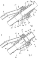
- Figures 2 and 3 are lateral sectioned views of the filling device 1 according to the invention, a dispensing valve 40 being introduced into the filling connection piece 1 in Figure 2 , and the filling connection piece 1 being illustrated alone in Figure 3 in lateral cross-section.
- the filling connection piece 1 comprises an upper portion 10, in which a dispensing valve 40 can be introduced and a lower portion 20 which can be brought into fluid connection with the filling pipe 2.
- the upper portion 10 can be connected to the lower portion 20 by securing means.
- the upper portion 10 comprises a mouth hole connection piece 11, in which there is provided at least one axially extending ventilation channel 18 which is surrounded by an outer wall 14 and an inner wall 14b which is radially spaced apart therefrom.
- the ventilation channel 18 serves to ventilate the operating fluid container 3 when the container 3 is filled with an operating fluid.
- a ventilation gas flow which acts counter to the filling volume flow is produced in the ventilation channel 18.
- a threaded collar 13 onto which a refilling container which is not illustrated in the Figures can be screwed in order to alternatively fill the operating fluid container 3 by means of the refilling container.
- the lower portion 20 of the filling connection piece 1 comprises a connection piece 21 which can be brought into fluid connection with the filling channel 2, a compensation chamber 24 and a connection 4 for the refuelling ventilation line 5.
- the connection 4 opens in the compensation chamber 24 so that the refuelling ventilation line 5 is connected in fluid terms to the compensation chamber 24.
- connection piece 21 has in the region facing the filling pipe 2 a fir-tree-like profile so that the filling pipe 2 can be pushed onto the corresponding portion of the connection piece 21.
- the filling connection piece 1 it is also readily possible for the filling connection piece 1 to have in the region facing the filling pipe 2 a connection flange which is not illustrated in the Figures and which can be connected to a connection flange of the filling pipe 2, which flange is also not illustrated in the Figures. It is further also readily possible for the filling pipe to be welded to the filling connection piece 1.
- connection piece 21 protrudes into the compensation chamber 24.
- the connection piece 21 faces the mouth hole connection piece 11 and is arranged so as to be spaced apart therefrom. Consequently, the connection piece 21 is surrounded by the compensation chamber 24, the connection piece 21 being radially spaced apart from a compensation chamber wall 25 which delimits the compensation chamber 24.
- the mouth hole connection piece 11 is connected in fluid terms to the compensation chamber 24 and the connection piece 21 is arranged between the operating fluid container 3 and the compensation chamber 24 and connected in fluid terms both to the operating fluid container 3 and the compensation chamber 24.
- the dispensing valve 40 can be introduced into the mouth hole connection piece through a mouth hole opening 12 of the mouth hole connection piece 11. Since the mouth hole connection piece 11 is arranged facing the connection piece 21, the dispensing valve 40 can be introduced directly into the connection piece 21 so that, in order to close a switch-off opening 41a, 41b, 41c by the operating fluid, the compensation chamber 24 does not have to be filled with the operating fluid beforehand.
- connection piece 21 there is provided in the connection piece 21 a material recess 23b which extends in an axial direction over at least a partial length of the connection piece 21 which is located in the compensation chamber 24. Furthermore, the connection piece 21 comprises an additional material recess 23a, which extends substantially over the entire longitudinal extent of the connection piece 21.
- connection piece 21 is in fluid connection with the compensation chamber 24 so that operating fluid which is located in the connection piece 21 can be discharged via the slots 23a, 23b into the compensation chamber 24. It is thus possible, for example, after a refuelling operation is complete, for the operating fluid which is located in the compensation chamber 24 to flow through the material recess 23a completely into the connection piece 21 and thereby to flow back into the operating fluid container 3.
- annular magnet 30 which in the installation position of the filling connection piece 1 is retained by means of a retention plate 26 of the lower portion 20 of the filling connection piece 1.
- the dispensing valve 40 can be guided in this instance through the annular space of the annular magnet 30 and can be switched by means of the annular magnet 30.
Landscapes
- Engineering & Computer Science (AREA)
- Chemical & Material Sciences (AREA)
- Mechanical Engineering (AREA)
- Combustion & Propulsion (AREA)
- Transportation (AREA)
- Sustainable Energy (AREA)
- Life Sciences & Earth Sciences (AREA)
- Sustainable Development (AREA)
- Chemical Kinetics & Catalysis (AREA)
- Health & Medical Sciences (AREA)
- Toxicology (AREA)
- General Engineering & Computer Science (AREA)
- Filling Of Jars Or Cans And Processes For Cleaning And Sealing Jars (AREA)
- Cooling, Air Intake And Gas Exhaust, And Fuel Tank Arrangements In Propulsion Units (AREA)
- Loading And Unloading Of Fuel Tanks Or Ships (AREA)
Description
- The invention relates to a filling device for a motor vehicle operating fluid container, the filling device comprising a mouth hole connection piece into which a dispensing valve can be introduced in order to fill the operating fluid container, a compensation chamber which is connected in fluid terms to the mouth hole connection piece and a connection piece which is arranged between the operating fluid container and the compensation chamber and which is connected in fluid terms to the operating fluid container and the compensation chamber.
- The operating fluid container may be a fuel container, a urea container for use in an SCR method (selective catalytic reduction) or another motor vehicle operating fluid container.
- When motor vehicle operating fluid containers are filled, for example, using a dispensing valve, operating fluid can be discharged via a filling device which is constructed as a filling connection piece. When a valve is switched off by means of a snifting hole/switch-off hole on the dispensing valve, the pressure surges which are produced in this instance lead to a fluid quantity which rises and falls back and which, depending on the configuration of the filling connection piece, can also sometimes spray outwards from the filling connection piece. In particular during filling with urea, this leads to non-desirable external contamination on the filling connection piece and on the vehicle.
- In the event of so-called "spitback", as a result of the dispensing valve being switched off and the associated formation of waves in the filling connection piece, drops of operating fluid are thus sprayed from the filling connection piece through ventilation openings. In the event of so-called "splashback", as a result of the dispensing valve being switched off and/or as a result of the impact of the operating fluid which is being discharged from the dispensing valve on a fluid column during the filling operation, relatively large quantities of fluid are discharged from ventilation openings of the filling connection piece. Furthermore, in the event of so-called "blowout", droplets of fluid can be discharged from the operating fluid container during the filling operation from the filling head or from the filling connection piece when the ventilation flow which is being discharged from the ventilation openings strikes the operating fluid being discharged from the dispensing valve and carries it through the ventilation openings.
- In order to reduce the quantity of operating fluid being discharged from the filling connection piece, it is known from the prior art to provide in the filling connection piece at least one compensation chamber which is connected in fluid terms both to the mouth hole connection piece and to the filling pipe. The surging movements which are brought about when the dispensing valve is switched off and/or switched on or waves of the operating fluid are reduced by the compensation chamber, the reduction or damping of the waves increasing with the volume of the compensation chamber.
- On the one hand, the operating fluid being discharged from the operating fluid container when it is filled is intended to be reduced and, on the other hand, the size of the filling connection piece is intended to be reduced since the structural space available in the motor vehicle is limited. Thus, for instance, in the event of a motor vehicle which is operated with diesel, both the fuel filling connection piece and the urea filling connection piece are often arranged behind a common covering flap, whereby the structural space which is available is extremely limited. Generic
WO 2012/139631 A1 describes a filler neck for a liquid tank for urea on motor vehicles, having a connection piece which is directly or indirectly connected to a component of the motor vehicle and/or to the liquid tank and having a removable sealing cover, wherein the connection piece has an axially running filler neck section which is designed both to receive, in a plunging manner, a nozzle for the urea and to hold, in attachable manner, a bottle filled with the urea. Inside the connection piece a filter element is arranged which face side is arranged towards the urea tank. - These two objectives described above have previously not been able to be combined with each other since the more compact the construction of the filling connection piece, the more operating fluid is discharged from the filling connection piece during the filling operation.
- There is known from
DE 10 2011 009 745 A1 a generic filling connection piece, in which a filling channel merges via an increase in diameter into the compensation chamber. A filling spout is arranged in the compensation chamber. A dispensing valve can be introduced through a mouth hole connection piece into the filling spout and consequently into the compensation chamber. When the operating fluid container is filled, the operating fluid flows from the dispensing valve through the compensation chamber into the filling channel in which, after a ventilation valve which is arranged in the operating fluid container has been closed, the operating fluid level increases. After the upper end of the filling channel has been reached, the operating fluid level also increases in the compensation chamber until the operating fluid reaches a switch-off opening/snifting opening of the dispensing valve which is located in the compensation chamber, whereby the filling operation is automatically ended. The action of the dispensing valve being switched off produces pressure surges which lead to a rising and falling fluid quantity. The wave energy which is produced in this manner is reduced in the compensation chamber. - The filling connection piece known from
DE 10 2011 009 745 A1 - An object of the present invention is to provide an improved filling device which has a small discharge of operating fluid through the filling device during the filling operation and which has a small size, a reduced number of individual components, and to ensure consistent switching-off reliability which is independent of the position of the switch-off opening/snifting hole.
- The object of the present invention is solved by a filling device having the features of
Claim 1. Advantageous embodiments are described in the dependent claims. - More specifically, the filling device according to the invention is distinguished in that a connection piece protrudes into the compensation chamber, the connection piece being arranged so as to face the mouth hole connection piece and to be spaced apart therefrom. In this instance, the connection piece is surrounded by the compensation chamber. A dispensing valve can be introduced through the mouth hole connection piece directly into the connection piece.
- The compensation chamber, which can also be referred to as a surge chamber, as a relaxation space and/or as a compensation space, serves to absorb and reduce the wave energy of operating fluid located in the filling device. A wave movement of operating fluid located in the filling device can be brought about by the dispensing valve being switched off. Furthermore, a wave movement of operating fluid located in the filling device can also be caused by fluid which is discharged from the dispensing valve striking a fluid surface inside the filling device. As a result of the provision of the compensation chamber, a reduced quantity of fluid is discharged from the filling device.
- The connection piece is consequently surrounded by the compensation chamber and at least partially spaced apart from the compensation chamber wall in a radial direction. The connection piece is consequently located in the compensation space of the compensation chamber.
- The inlet channel of the mouth hole connection piece opens in the compensation chamber. In this instance, the mouth hole connection piece and the connection piece face each other in such a manner that a dispensing valve can be introduced through the mouth hole connection piece into the connection piece.
- When the operating fluid container is filled with an operating fluid via the filling device which can also be referred to as a filling connection piece, the operating fluid level in the filling pipe rises after a ventilation valve which is arranged in the operating fluid container has been closed. After the upper end of the filling pipe has been reached, the operating fluid level in the connection piece which is connected to the filling pipe increases until the operating fluid closes a switch-off opening in the dispensing valve. Since the connection piece protrudes into the compensation chamber and is surrounded by the compensation chamber, the operating fluid level inside the connection piece which is surrounded by the compensation chamber is always higher than the operating fluid level in the compensation chamber. Consequently, when the operating fluid chamber is filled, the compensation chamber is arranged downstream of the connection piece since the operating fluid when the operating fluid container is filled first rises in the connection piece, before it can reach the compensation space via the fluid connection to the compensation chamber.
- Since the dispensing valve opens directly in the connection piece, when the operating fluid container is filled the operating fluid level within the connection piece rises rapidly so that the operating fluid reaches the switch-off opening of the dispensing valve before the operating fluid expands into the compensation chamber. As a result of the rapid increase of the operating fluid level within the connection piece during the filling operation, the dispensing valve switches off substantially independently of the positioning of the switch-off opening in the dispensing valve. Consequently, the filling device according to the invention can be used for different dispensing valves which have switch-off openings at different positions.
- Furthermore, the internal tank pressure within the operating fluid container is reduced after the filling operation is automatically switched off in comparison with filling connection pieces known from the prior art since, before the automatic switching-off operation, the compensation chamber does not have to be flooded with the operating fluid so that a smaller operating fluid column applies pressure to the operating fluid in the operating fluid container. As a result of the smaller internal tank pressure, less operating fluid is also urged out of ventilation channels provided in the filling device so that the spitback and the splashback are reduced.
- The filling device according to the invention does not require any separate filling spout so that the number of components of the filling device according to the invention is reduced. Consequently, the production costs for the filling device according to the invention and the complexity for the assembly thereof are reduced. Furthermore, the filling device according to the invention is very compact so that, for example, in the event of a motor vehicle which is operated with diesel, a diesel filling connection piece can be positioned beside a urea filling connection piece underneath a common covering flap.
- The connection piece preferably has at least one discharge opening, by means of which the connection piece is connected in fluid terms to the compensation chamber. The sizing of the opening is such that, when the operating fluid container is filled, more fluid flows from the dispensing nozzle into the connection piece than flows through the discharge opening into the compensation chamber. It can thereby be ensured that the operating fluid level within the connection piece located in the compensation chamber is always higher than the operating fluid level in the compensation chamber.
- Preferably in this instance, the discharge opening in the installation position of the filling device is arranged in the lower region of the connection piece which is located in the compensation chamber. It is thereby ensured that, after a filling operation, the operating fluid located in the compensation space or in the compensation chamber flows away into the connection piece and consequently into the operating fluid container.
- The connection piece preferably has at least one material recess which extends in an axial direction over at least a partial length of the connection piece which is located in the compensation chamber. This material recess may also be referred to as a slot or a gap.
- The material recess preferably extends substantially over the entire length of the connection piece which is located in the compensation chamber.
- By means of the material recesses in the connection piece, improved overflow from the connection piece into the compensation chamber is achieved.
- The dispensing valve can preferably be brought into direct contact with the connection piece.
- The connection piece preferably tapers in the direction of the operating fluid container.
- In the last two construction variants, the inclination of the filling connection piece for splashback and spitback is reduced again since less operating fluid can enter the intermediate space between the connection piece and the dispensing valve.
- Other advantages, details and features of the invention will be appreciated below from the embodiments which are explained. In detail:
-
Figure 1 is a cross-section through an operating fluid container with a filling device according to the invention; -
Figure 2 is a lateral sectioned view of the filling device according to the invention with the dispensing valve inserted therein; and -
Figure 3 shows the filling device illustrated inFigure 2 without any dispensing valve inserted. - In the description which now follows, reference numerals which are the same refer to components which are identical or features which are identical so that a description which is given with reference to a Figure in relation to a component also applies to the other Figures so that repetition of the description is prevented.
- As can be seen in
Figure 1 , the fillingdevice 1 or thefilling connection piece 1 according to the invention is arranged on a filling pipe 2 of an operatingfluid container 3. In the embodiment described, this operatingfluid container 3 is constructed as aurea container 3 for a fluid urea solution as a reduction agent for the catalytic exhaust gas denitrification in a motor vehicle. - The operating
fluid container 3 may be constructed as an integral extrusion blow-moulded plastics container. The filling pipe 2 and thefilling connection piece 1 may also comprise thermoplastic plastics material. The fillingconnection piece 1 and the remaining components described may also be produced with an injection-moulding method. In the embodiment described, the entire arrangement comprising thefilling connection piece 1, filling pipe 2 and operatingfluid container 3 is constructed in several pieces. The fillingconnection piece 1 is, as described below, constructed as a filling head having aconnection 4 for arefuelling ventilation line 5. Therefuelling ventilation line 5 opens via an immersion pipe 6 as a switching-off fitting in a predetermined ventilation position in the operatingfluid container 3. - The
refuelling ventilation line 5 is guided from the operatingfluid container 3 to thefilling connection piece 1 via acompensation container 7 which acts as a collection container for any fluid which occurs in therefuelling ventilation line 5. When the operatingfluid container 3 is filled, a urea solution is directed into the operatingfluid container 3 via a dispensing valve 40 (seeFigure 2 ) with the result that the fluid level rises therein and the gas present in the operatingfluid container 3 is urged via therefuelling ventilation line 5 towards the fillingconnection piece 1 until the rising fluid level closes the immersion pipe 6. Then, the fluid level in the filling pipe 2 rises until it reaches a switch-off hole 41a, 41b, 41c at the dispensing valve 40 and closes it, with the result that a switching operation of the dispensing valve 40 is actuated. The refuelling operation is consequently ended. -
Figures 2 and 3 are lateral sectioned views of thefilling device 1 according to the invention, a dispensing valve 40 being introduced into thefilling connection piece 1 inFigure 2 , and thefilling connection piece 1 being illustrated alone inFigure 3 in lateral cross-section. - The filling
connection piece 1 comprises anupper portion 10, in which a dispensing valve 40 can be introduced and alower portion 20 which can be brought into fluid connection with the filling pipe 2. Theupper portion 10 can be connected to thelower portion 20 by securing means. - The
upper portion 10 comprises a mouthhole connection piece 11, in which there is provided at least one axially extendingventilation channel 18 which is surrounded by an outer wall 14 and an inner wall 14b which is radially spaced apart therefrom. Theventilation channel 18 serves to ventilate the operatingfluid container 3 when thecontainer 3 is filled with an operating fluid. When the operatingfluid container 3 is filled, a ventilation gas flow which acts counter to the filling volume flow is produced in theventilation channel 18. - There is provided on the outer side of the mouth hole connection piece a threaded
collar 13, onto which a refilling container which is not illustrated in the Figures can be screwed in order to alternatively fill the operatingfluid container 3 by means of the refilling container. - The
lower portion 20 of thefilling connection piece 1 comprises aconnection piece 21 which can be brought into fluid connection with the filling channel 2, acompensation chamber 24 and aconnection 4 for therefuelling ventilation line 5. Theconnection 4 opens in thecompensation chamber 24 so that therefuelling ventilation line 5 is connected in fluid terms to thecompensation chamber 24. - In
Figures 2 and 3 , it can be seen that theconnection piece 21 has in the region facing the filling pipe 2 a fir-tree-like profile so that the filling pipe 2 can be pushed onto the corresponding portion of theconnection piece 21. However, it is also readily possible for thefilling connection piece 1 to have in the region facing the filling pipe 2 a connection flange which is not illustrated in the Figures and which can be connected to a connection flange of the filling pipe 2, which flange is also not illustrated in the Figures. It is further also readily possible for the filling pipe to be welded to thefilling connection piece 1. - In the drawings, it can be seen that the
filling connection piece 21 protrudes into thecompensation chamber 24. Theconnection piece 21 faces the mouthhole connection piece 11 and is arranged so as to be spaced apart therefrom. Consequently, theconnection piece 21 is surrounded by thecompensation chamber 24, theconnection piece 21 being radially spaced apart from acompensation chamber wall 25 which delimits thecompensation chamber 24. - The mouth
hole connection piece 11 is connected in fluid terms to thecompensation chamber 24 and theconnection piece 21 is arranged between the operatingfluid container 3 and thecompensation chamber 24 and connected in fluid terms both to the operatingfluid container 3 and thecompensation chamber 24. The dispensing valve 40 can be introduced into the mouth hole connection piece through a mouth hole opening 12 of the mouthhole connection piece 11. Since the mouthhole connection piece 11 is arranged facing theconnection piece 21, the dispensing valve 40 can be introduced directly into theconnection piece 21 so that, in order to close a switch-off opening 41a, 41b, 41c by the operating fluid, thecompensation chamber 24 does not have to be filled with the operating fluid beforehand. - As a result of the rapid rise of the operating fluid level in the
connection piece 21 during the refuelling operation, the positioning of the switch-off opening or snifting opening 41a, 41b, 41c is unproblematic. InFigure 2 , it can be seen that different positionings for the switch-off opening are possible and that with all three switch-off openings 41a, 41b, 41c which are illustrated the automatic switch-off action in thefilling connection piece 1 according to the invention functions in a problem-free manner since, during the refuelling operation, the operating fluid level reaches each location of the dispensing valve 40 in which a switch-off opening 41a, 41b, 41c can be provided at substantially the same time. - It can be seen in
Figure 3 that there is provided in the connection piece 21 a material recess 23b which extends in an axial direction over at least a partial length of theconnection piece 21 which is located in thecompensation chamber 24. Furthermore, theconnection piece 21 comprises an additional material recess 23a, which extends substantially over the entire longitudinal extent of theconnection piece 21. - By means of these slots 23a, 23b, the
connection piece 21 is in fluid connection with thecompensation chamber 24 so that operating fluid which is located in theconnection piece 21 can be discharged via the slots 23a, 23b into thecompensation chamber 24. It is thus possible, for example, after a refuelling operation is complete, for the operating fluid which is located in thecompensation chamber 24 to flow through the material recess 23a completely into theconnection piece 21 and thereby to flow back into the operatingfluid container 3. - In the Figures, it can further be seen that, in a free space of the
upper portion 10 of thefilling connection piece 1, there is inserted anannular magnet 30 which in the installation position of thefilling connection piece 1 is retained by means of aretention plate 26 of thelower portion 20 of thefilling connection piece 1. The dispensing valve 40 can be guided in this instance through the annular space of theannular magnet 30 and can be switched by means of theannular magnet 30. -
- 1
- Filling device/filling connection piece
- 2
- Filling pipe
- 3
- Operating fluid container
- 4
- Connection for refuelling ventilation line
- 5
- Refuelling ventilation line
- 6
- Immersion pipe
- 7
- Compensation container
- 10
- Upper portion of the filling connection piece
- 11
- Mouth hole connection piece
- 12
- Mouth hole opening/mouth hole
- 13
- Threaded collar
- 14a
- Outer wall (of the wall)
- 14b
- Inner wall (of the wall)
- 18
- Ventilation channel
- 20
- Lower portion of the filling connection piece
- 21
- Connection piece
- 23a, 23b
- Material recess/discharge opening/overflow opening
- 24
- Compensation chamber
- 25
- Compensation chamber wall
- 26
- Retention plate (for annular magnet)
- 30
- Annular magnet
- 40
- Dispensing valve
- 41a, 41b, 41c
- Switch-off opening/snifting opening
Claims (7)
- Filling device (1) for an operating fluid container (3) for a motor vehicle, comprising:- a mouth hole connection piece (11) into which a dispensing valve (40) can be introduced in order to fill the operating fluid container (3),- a compensation chamber (24) to which the mouth hole connection piece (11) is connected in fluid terms; characterised by- a connection piece (21) which is arranged between the operating fluid container (3) and the compensation chamber (24) and which is connected in fluid terms to the operating fluid container (3) and the compensation chamber (24), wherein the filling connection piece (1) has the following features:- the connection piece (21) protrudes into the compensation chamber (24);- the connection piece (21) is arranged so as to face the mouth hole connection piece (11) and to be spaced apart therefrom;- the connection piece (21) is surrounded by the compensation chamber (24) so that, when the operating fluid level in the filling device (1) rises, the operating fluid level inside the connection piece (21) is always higher than the operating fluid level in the compensation chamber (24); and- a dispensing valve (40) can be introduced through the mouth hole connection piece (11) into the connection piece (21).
- Filling device (1) according to claim 1, characterised in that the connection piece (21) has at least one discharge opening, by means of which the connection piece (21) is connected in fluid terms to the compensation chamber (24).
- Filling device (1) according to claim 2, characterised in that the discharge opening in the installation position of the filling device (1) is arranged in the lower region of the connection piece (21) which is located in the compensation chamber (24).
- Filling device (1) according to any one of the preceding claims, characterised in that the connection piece (21) has at least one material recess (23a) which extends in an axial direction over at least a partial length of the connection piece (21) which is located in the compensation chamber (24).
- Filling device (1) according to claim 4, characterised in that the material recess (23a) extends substantially over the entire length of the connection piece (21) which is located in the compensation chamber (24).
- Filling device (1) according to any one of the preceding claims, characterised in that the dispensing valve (40) can be brought into direct contact with the connection piece (21).
- Filling device (1) according to any one of the preceding claims, characterised in that the connection piece (21) tapers in the direction of the operating fluid container (3).
Applications Claiming Priority (2)
| Application Number | Priority Date | Filing Date | Title |
|---|---|---|---|
| DE102013016683.7A DE102013016683A1 (en) | 2013-10-09 | 2013-10-09 | Filling device for a motor vehicle operating fluid container |
| PCT/EP2014/071412 WO2015052168A1 (en) | 2013-10-09 | 2014-10-07 | Filling device for a motor vehicle operating fluid container |
Publications (2)
| Publication Number | Publication Date |
|---|---|
| EP3055155A1 EP3055155A1 (en) | 2016-08-17 |
| EP3055155B1 true EP3055155B1 (en) | 2017-07-19 |
Family
ID=51663178
Family Applications (1)
| Application Number | Title | Priority Date | Filing Date |
|---|---|---|---|
| EP14781525.2A Active EP3055155B1 (en) | 2013-10-09 | 2014-10-07 | Filling device for a motor vehicle operating fluid container |
Country Status (5)
| Country | Link |
|---|---|
| US (1) | US9669706B2 (en) |
| EP (1) | EP3055155B1 (en) |
| CN (1) | CN105612075B (en) |
| DE (1) | DE102013016683A1 (en) |
| WO (1) | WO2015052168A1 (en) |
Families Citing this family (15)
| Publication number | Priority date | Publication date | Assignee | Title |
|---|---|---|---|---|
| DE102014220333A1 (en) * | 2014-10-07 | 2016-04-07 | Röchling Automotive SE & Co. KG | Liquid container, in particular urea solution container, for a vehicle |
| US20190001812A1 (en) * | 2014-11-20 | 2019-01-03 | Buddy Moore | Pre-consumption fuel analytics system |
| JP6307053B2 (en) * | 2015-09-28 | 2018-04-04 | 豊田合成株式会社 | Fuel supply device |
| DE102015220125B4 (en) * | 2015-10-15 | 2022-08-25 | Röchling Automotive SE & Co. KG | tank filler neck |
| FR3051736B1 (en) | 2016-05-27 | 2020-09-04 | Coutier Moulage Gen Ind | FILLING HEAD FOR FILLING A TANK WITH A LIQUID |
| JP6389228B2 (en) * | 2016-11-25 | 2018-09-12 | コリア、フューエル−テク、コーポレイションKorea Fuel−Tech Corporation | Filler neck assembly and manufacturing method thereof |
| KR102261541B1 (en) * | 2017-02-15 | 2021-06-04 | 현대자동차주식회사 | Urea filling device for diesel vehicle |
| US10245529B2 (en) * | 2017-02-27 | 2019-04-02 | GM Global Technology Operations LLC | System and apparatus to improve venting and spill mitigation for tank |
| US10640358B2 (en) * | 2017-06-21 | 2020-05-05 | Ford Global Technologies, Llc | Capless refill adapter for a fluid refilling system |
| GB2568094B (en) * | 2017-11-06 | 2020-04-08 | Jaguar Land Rover Ltd | Filler head body for a reductant reservoir assembly |
| JP7061900B2 (en) * | 2018-03-09 | 2022-05-02 | 株式会社Fts | Fuel supply device |
| JP7468985B2 (en) * | 2018-03-22 | 2024-04-16 | 住友建機株式会社 | Excavator |
| KR102727901B1 (en) * | 2019-04-29 | 2024-11-07 | 현대자동차주식회사 | Opening-closing device for urea water inlet of vehicle |
| EP3748088B1 (en) * | 2019-06-05 | 2021-11-03 | Ford Global Technologies, LLC | Assembly for an urea tank system |
| US12691989B2 (en) | 2022-10-28 | 2026-07-28 | Big Dog Marine Llc | Deck fill for use in vehicles |
Family Cites Families (7)
| Publication number | Priority date | Publication date | Assignee | Title |
|---|---|---|---|---|
| US4706708A (en) * | 1986-06-23 | 1987-11-17 | General Motors Corporation | Fuel tank venting |
| US5503199A (en) * | 1994-03-21 | 1996-04-02 | Attwood Corporation | Fuel fill devices for boats |
| JP4894701B2 (en) * | 2007-09-28 | 2012-03-14 | 豊田合成株式会社 | Filler neck |
| JP5266906B2 (en) * | 2008-06-23 | 2013-08-21 | 日産自動車株式会社 | Lubrication nozzle insertion part structure |
| DE102011009745B4 (en) | 2011-01-28 | 2012-09-13 | Kautex Textron Gmbh & Co. Kg | Filler neck for a secondary fluid tank |
| EP2665901B1 (en) * | 2011-04-12 | 2014-11-05 | Reutter GmbH | Filler neck for a liquid tank, in particular a urea tank, on motor vehicles |
| DE102011017200A1 (en) | 2011-04-15 | 2012-10-18 | Daimler Ag | An adjusting device for variably setting at least one compression ratio of an internal combustion engine |
-
2013
- 2013-10-09 DE DE102013016683.7A patent/DE102013016683A1/en not_active Ceased
-
2014
- 2014-10-07 EP EP14781525.2A patent/EP3055155B1/en active Active
- 2014-10-07 WO PCT/EP2014/071412 patent/WO2015052168A1/en not_active Ceased
- 2014-10-07 US US15/028,686 patent/US9669706B2/en active Active
- 2014-10-07 CN CN201480055775.7A patent/CN105612075B/en active Active
Non-Patent Citations (1)
| Title |
|---|
| None * |
Also Published As
| Publication number | Publication date |
|---|---|
| CN105612075A (en) | 2016-05-25 |
| US9669706B2 (en) | 2017-06-06 |
| CN105612075B (en) | 2018-05-08 |
| WO2015052168A1 (en) | 2015-04-16 |
| DE102013016683A1 (en) | 2015-04-09 |
| US20160263991A1 (en) | 2016-09-15 |
| EP3055155A1 (en) | 2016-08-17 |
Similar Documents
| Publication | Publication Date | Title |
|---|---|---|
| US9669706B2 (en) | Filling device for a motor vehicle operating fluid container | |
| EP2668055B1 (en) | Filler neck for an auxiliary liquid reservoir | |
| US9539898B2 (en) | Filler head | |
| US8800611B2 (en) | Insert element for a container suitable for filling with urea at a filling station | |
| US9776502B2 (en) | Filler neck for a motor vehicle operating-liquid tank | |
| US10190458B2 (en) | Storage tank for aqueous urea solution in a motor vehicle | |
| EP2632757B1 (en) | Fuel tank for motor vehicles | |
| CN108361231B (en) | Lubricant reservoir for a hydraulic system | |
| KR20180033534A (en) | Injection valve, exhaust gas aftertreatment system | |
| EP2736751B1 (en) | Liquid container for a motor vehicle, in particular a fuel container | |
| JP3167339U (en) | Pump structure for foam generation | |
| US10464698B2 (en) | Filling head for filling a tank with a liquid | |
| US20140202593A1 (en) | Device for filling a tank of a motor vehicle | |
| US9539776B2 (en) | Filling connector with integrated ventilation duct | |
| CN105750094A (en) | Reagent adding system of flotation column and reagent adding method | |
| CN205868553U (en) | Flotation column medicine system | |
| KR102394772B1 (en) | System for preventing overflow during oil supply | |
| JP2004144051A (en) | Fuel shutoff valve device | |
| US20200360839A1 (en) | Venting device for venting a motor vehicle tank | |
| CN106809004A (en) | Filler Neck | |
| KR102463411B1 (en) | Device for preventing fuel overflow of vehicle fuel system | |
| JP7588563B2 (en) | Trigger-type liquid ejector | |
| JP2025523937A (en) | Filling head for reliable, splash-free refilling | |
| CN101358537B (en) | Sand warehouse for mine packing means | |
| CN201071735Y (en) | For sand bins in mine filling equipment |
Legal Events
| Date | Code | Title | Description |
|---|---|---|---|
| PUAI | Public reference made under article 153(3) epc to a published international application that has entered the european phase |
Free format text: ORIGINAL CODE: 0009012 |
|
| 17P | Request for examination filed |
Effective date: 20160502 |
|
| AK | Designated contracting states |
Kind code of ref document: A1 Designated state(s): AL AT BE BG CH CY CZ DE DK EE ES FI FR GB GR HR HU IE IS IT LI LT LU LV MC MK MT NL NO PL PT RO RS SE SI SK SM TR |
|
| AX | Request for extension of the european patent |
Extension state: BA ME |
|
| DAX | Request for extension of the european patent (deleted) | ||
| GRAP | Despatch of communication of intention to grant a patent |
Free format text: ORIGINAL CODE: EPIDOSNIGR1 |
|
| INTG | Intention to grant announced |
Effective date: 20170419 |
|
| GRAS | Grant fee paid |
Free format text: ORIGINAL CODE: EPIDOSNIGR3 |
|
| GRAA | (expected) grant |
Free format text: ORIGINAL CODE: 0009210 |
|
| AK | Designated contracting states |
Kind code of ref document: B1 Designated state(s): AL AT BE BG CH CY CZ DE DK EE ES FI FR GB GR HR HU IE IS IT LI LT LU LV MC MK MT NL NO PL PT RO RS SE SI SK SM TR |
|
| REG | Reference to a national code |
Ref country code: GB Ref legal event code: FG4D |
|
| REG | Reference to a national code |
Ref country code: DE Ref legal event code: R082 Ref document number: 602014012080 Country of ref document: DE Representative=s name: KIERDORF RITSCHEL RICHLY PATENTANWAELTE PARTG , DE Ref country code: DE Ref legal event code: R082 Ref document number: 602014012080 Country of ref document: DE Representative=s name: RICHLY & RITSCHEL PATENTANWAELTE PARTG MBB, DE |
|
| REG | Reference to a national code |
Ref country code: CH Ref legal event code: EP |
|
| REG | Reference to a national code |
Ref country code: IE Ref legal event code: FG4D |
|
| REG | Reference to a national code |
Ref country code: AT Ref legal event code: REF Ref document number: 910026 Country of ref document: AT Kind code of ref document: T Effective date: 20170815 |
|
| REG | Reference to a national code |
Ref country code: DE Ref legal event code: R096 Ref document number: 602014012080 Country of ref document: DE |
|
| REG | Reference to a national code |
Ref country code: FR Ref legal event code: PLFP Year of fee payment: 4 |
|
| REG | Reference to a national code |
Ref country code: NL Ref legal event code: MP Effective date: 20170719 |
|
| REG | Reference to a national code |
Ref country code: LT Ref legal event code: MG4D |
|
| REG | Reference to a national code |
Ref country code: AT Ref legal event code: MK05 Ref document number: 910026 Country of ref document: AT Kind code of ref document: T Effective date: 20170719 |
|
| PG25 | Lapsed in a contracting state [announced via postgrant information from national office to epo] |
Ref country code: SE Free format text: LAPSE BECAUSE OF FAILURE TO SUBMIT A TRANSLATION OF THE DESCRIPTION OR TO PAY THE FEE WITHIN THE PRESCRIBED TIME-LIMIT Effective date: 20170719 Ref country code: HR Free format text: LAPSE BECAUSE OF FAILURE TO SUBMIT A TRANSLATION OF THE DESCRIPTION OR TO PAY THE FEE WITHIN THE PRESCRIBED TIME-LIMIT Effective date: 20170719 Ref country code: LT Free format text: LAPSE BECAUSE OF FAILURE TO SUBMIT A TRANSLATION OF THE DESCRIPTION OR TO PAY THE FEE WITHIN THE PRESCRIBED TIME-LIMIT Effective date: 20170719 Ref country code: AT Free format text: LAPSE BECAUSE OF FAILURE TO SUBMIT A TRANSLATION OF THE DESCRIPTION OR TO PAY THE FEE WITHIN THE PRESCRIBED TIME-LIMIT Effective date: 20170719 Ref country code: FI Free format text: LAPSE BECAUSE OF FAILURE TO SUBMIT A TRANSLATION OF THE DESCRIPTION OR TO PAY THE FEE WITHIN THE PRESCRIBED TIME-LIMIT Effective date: 20170719 Ref country code: NL Free format text: LAPSE BECAUSE OF FAILURE TO SUBMIT A TRANSLATION OF THE DESCRIPTION OR TO PAY THE FEE WITHIN THE PRESCRIBED TIME-LIMIT Effective date: 20170719 Ref country code: NO Free format text: LAPSE BECAUSE OF FAILURE TO SUBMIT A TRANSLATION OF THE DESCRIPTION OR TO PAY THE FEE WITHIN THE PRESCRIBED TIME-LIMIT Effective date: 20171019 |
|
| PG25 | Lapsed in a contracting state [announced via postgrant information from national office to epo] |
Ref country code: LV Free format text: LAPSE BECAUSE OF FAILURE TO SUBMIT A TRANSLATION OF THE DESCRIPTION OR TO PAY THE FEE WITHIN THE PRESCRIBED TIME-LIMIT Effective date: 20170719 Ref country code: PL Free format text: LAPSE BECAUSE OF FAILURE TO SUBMIT A TRANSLATION OF THE DESCRIPTION OR TO PAY THE FEE WITHIN THE PRESCRIBED TIME-LIMIT Effective date: 20170719 Ref country code: GR Free format text: LAPSE BECAUSE OF FAILURE TO SUBMIT A TRANSLATION OF THE DESCRIPTION OR TO PAY THE FEE WITHIN THE PRESCRIBED TIME-LIMIT Effective date: 20171020 Ref country code: ES Free format text: LAPSE BECAUSE OF FAILURE TO SUBMIT A TRANSLATION OF THE DESCRIPTION OR TO PAY THE FEE WITHIN THE PRESCRIBED TIME-LIMIT Effective date: 20170719 Ref country code: IS Free format text: LAPSE BECAUSE OF FAILURE TO SUBMIT A TRANSLATION OF THE DESCRIPTION OR TO PAY THE FEE WITHIN THE PRESCRIBED TIME-LIMIT Effective date: 20171119 Ref country code: BG Free format text: LAPSE BECAUSE OF FAILURE TO SUBMIT A TRANSLATION OF THE DESCRIPTION OR TO PAY THE FEE WITHIN THE PRESCRIBED TIME-LIMIT Effective date: 20171019 Ref country code: RS Free format text: LAPSE BECAUSE OF FAILURE TO SUBMIT A TRANSLATION OF THE DESCRIPTION OR TO PAY THE FEE WITHIN THE PRESCRIBED TIME-LIMIT Effective date: 20170719 |
|
| REG | Reference to a national code |
Ref country code: DE Ref legal event code: R097 Ref document number: 602014012080 Country of ref document: DE |
|
| PG25 | Lapsed in a contracting state [announced via postgrant information from national office to epo] |
Ref country code: DK Free format text: LAPSE BECAUSE OF FAILURE TO SUBMIT A TRANSLATION OF THE DESCRIPTION OR TO PAY THE FEE WITHIN THE PRESCRIBED TIME-LIMIT Effective date: 20170719 Ref country code: RO Free format text: LAPSE BECAUSE OF FAILURE TO SUBMIT A TRANSLATION OF THE DESCRIPTION OR TO PAY THE FEE WITHIN THE PRESCRIBED TIME-LIMIT Effective date: 20170719 Ref country code: CZ Free format text: LAPSE BECAUSE OF FAILURE TO SUBMIT A TRANSLATION OF THE DESCRIPTION OR TO PAY THE FEE WITHIN THE PRESCRIBED TIME-LIMIT Effective date: 20170719 |
|
| PLBE | No opposition filed within time limit |
Free format text: ORIGINAL CODE: 0009261 |
|
| STAA | Information on the status of an ep patent application or granted ep patent |
Free format text: STATUS: NO OPPOSITION FILED WITHIN TIME LIMIT |
|
| PG25 | Lapsed in a contracting state [announced via postgrant information from national office to epo] |
Ref country code: SM Free format text: LAPSE BECAUSE OF FAILURE TO SUBMIT A TRANSLATION OF THE DESCRIPTION OR TO PAY THE FEE WITHIN THE PRESCRIBED TIME-LIMIT Effective date: 20170719 Ref country code: SK Free format text: LAPSE BECAUSE OF FAILURE TO SUBMIT A TRANSLATION OF THE DESCRIPTION OR TO PAY THE FEE WITHIN THE PRESCRIBED TIME-LIMIT Effective date: 20170719 Ref country code: MC Free format text: LAPSE BECAUSE OF FAILURE TO SUBMIT A TRANSLATION OF THE DESCRIPTION OR TO PAY THE FEE WITHIN THE PRESCRIBED TIME-LIMIT Effective date: 20170719 Ref country code: EE Free format text: LAPSE BECAUSE OF FAILURE TO SUBMIT A TRANSLATION OF THE DESCRIPTION OR TO PAY THE FEE WITHIN THE PRESCRIBED TIME-LIMIT Effective date: 20170719 Ref country code: IT Free format text: LAPSE BECAUSE OF FAILURE TO SUBMIT A TRANSLATION OF THE DESCRIPTION OR TO PAY THE FEE WITHIN THE PRESCRIBED TIME-LIMIT Effective date: 20170719 |
|
| REG | Reference to a national code |
Ref country code: CH Ref legal event code: PL |
|
| 26N | No opposition filed |
Effective date: 20180420 |
|
| REG | Reference to a national code |
Ref country code: IE Ref legal event code: MM4A |
|
| PG25 | Lapsed in a contracting state [announced via postgrant information from national office to epo] |
Ref country code: LI Free format text: LAPSE BECAUSE OF NON-PAYMENT OF DUE FEES Effective date: 20171031 Ref country code: LU Free format text: LAPSE BECAUSE OF NON-PAYMENT OF DUE FEES Effective date: 20171007 Ref country code: CH Free format text: LAPSE BECAUSE OF NON-PAYMENT OF DUE FEES Effective date: 20171031 |
|
| REG | Reference to a national code |
Ref country code: BE Ref legal event code: MM Effective date: 20171031 |
|
| PG25 | Lapsed in a contracting state [announced via postgrant information from national office to epo] |
Ref country code: SI Free format text: LAPSE BECAUSE OF FAILURE TO SUBMIT A TRANSLATION OF THE DESCRIPTION OR TO PAY THE FEE WITHIN THE PRESCRIBED TIME-LIMIT Effective date: 20170719 Ref country code: BE Free format text: LAPSE BECAUSE OF NON-PAYMENT OF DUE FEES Effective date: 20171031 |
|
| PG25 | Lapsed in a contracting state [announced via postgrant information from national office to epo] |
Ref country code: MT Free format text: LAPSE BECAUSE OF NON-PAYMENT OF DUE FEES Effective date: 20171007 |
|
| REG | Reference to a national code |
Ref country code: FR Ref legal event code: PLFP Year of fee payment: 5 |
|
| PG25 | Lapsed in a contracting state [announced via postgrant information from national office to epo] |
Ref country code: IE Free format text: LAPSE BECAUSE OF NON-PAYMENT OF DUE FEES Effective date: 20171007 |
|
| PG25 | Lapsed in a contracting state [announced via postgrant information from national office to epo] |
Ref country code: HU Free format text: LAPSE BECAUSE OF FAILURE TO SUBMIT A TRANSLATION OF THE DESCRIPTION OR TO PAY THE FEE WITHIN THE PRESCRIBED TIME-LIMIT; INVALID AB INITIO Effective date: 20141007 |
|
| PG25 | Lapsed in a contracting state [announced via postgrant information from national office to epo] |
Ref country code: CY Free format text: LAPSE BECAUSE OF FAILURE TO SUBMIT A TRANSLATION OF THE DESCRIPTION OR TO PAY THE FEE WITHIN THE PRESCRIBED TIME-LIMIT Effective date: 20170719 |
|
| PG25 | Lapsed in a contracting state [announced via postgrant information from national office to epo] |
Ref country code: MK Free format text: LAPSE BECAUSE OF FAILURE TO SUBMIT A TRANSLATION OF THE DESCRIPTION OR TO PAY THE FEE WITHIN THE PRESCRIBED TIME-LIMIT Effective date: 20170719 |
|
| PG25 | Lapsed in a contracting state [announced via postgrant information from national office to epo] |
Ref country code: TR Free format text: LAPSE BECAUSE OF FAILURE TO SUBMIT A TRANSLATION OF THE DESCRIPTION OR TO PAY THE FEE WITHIN THE PRESCRIBED TIME-LIMIT Effective date: 20170719 |
|
| PG25 | Lapsed in a contracting state [announced via postgrant information from national office to epo] |
Ref country code: PT Free format text: LAPSE BECAUSE OF FAILURE TO SUBMIT A TRANSLATION OF THE DESCRIPTION OR TO PAY THE FEE WITHIN THE PRESCRIBED TIME-LIMIT Effective date: 20170719 |
|
| PG25 | Lapsed in a contracting state [announced via postgrant information from national office to epo] |
Ref country code: AL Free format text: LAPSE BECAUSE OF FAILURE TO SUBMIT A TRANSLATION OF THE DESCRIPTION OR TO PAY THE FEE WITHIN THE PRESCRIBED TIME-LIMIT Effective date: 20170719 |
|
| P01 | Opt-out of the competence of the unified patent court (upc) registered |
Effective date: 20230526 |
|
| PGFP | Annual fee paid to national office [announced via postgrant information from national office to epo] |
Ref country code: DE Payment date: 20251007 Year of fee payment: 12 |
|
| PGFP | Annual fee paid to national office [announced via postgrant information from national office to epo] |
Ref country code: GB Payment date: 20251022 Year of fee payment: 12 |
|
| PGFP | Annual fee paid to national office [announced via postgrant information from national office to epo] |
Ref country code: FR Payment date: 20251030 Year of fee payment: 12 |