EP3055152B2 - Electric drive of mobile apparatus - Google Patents
Electric drive of mobile apparatus Download PDFInfo
- Publication number
- EP3055152B2 EP3055152B2 EP14790764.6A EP14790764A EP3055152B2 EP 3055152 B2 EP3055152 B2 EP 3055152B2 EP 14790764 A EP14790764 A EP 14790764A EP 3055152 B2 EP3055152 B2 EP 3055152B2
- Authority
- EP
- European Patent Office
- Prior art keywords
- drive
- energy
- electric motor
- main frame
- mobile apparatus
- Prior art date
- Legal status (The legal status is an assumption and is not a legal conclusion. Google has not performed a legal analysis and makes no representation as to the accuracy of the status listed.)
- Active
Links
Images


Classifications
-
- E—FIXED CONSTRUCTIONS
- E02—HYDRAULIC ENGINEERING; FOUNDATIONS; SOIL SHIFTING
- E02F—DREDGING; SOIL-SHIFTING
- E02F9/00—Component parts of dredgers or soil-shifting machines, not restricted to one of the kinds covered by groups E02F3/00 - E02F7/00
- E02F9/20—Drives; Control devices
- E02F9/2058—Electric or electro-mechanical or mechanical control devices of vehicle sub-units
-
- B—PERFORMING OPERATIONS; TRANSPORTING
- B60—VEHICLES IN GENERAL
- B60K—ARRANGEMENT OR MOUNTING OF PROPULSION UNITS OR OF TRANSMISSIONS IN VEHICLES; ARRANGEMENT OR MOUNTING OF PLURAL DIVERSE PRIME-MOVERS IN VEHICLES; AUXILIARY DRIVES FOR VEHICLES; INSTRUMENTATION OR DASHBOARDS FOR VEHICLES; ARRANGEMENTS IN CONNECTION WITH COOLING, AIR INTAKE, GAS EXHAUST OR FUEL SUPPLY OF PROPULSION UNITS IN VEHICLES
- B60K25/00—Auxiliary drives
- B60K25/02—Auxiliary drives directly from an engine shaft
-
- B—PERFORMING OPERATIONS; TRANSPORTING
- B60—VEHICLES IN GENERAL
- B60K—ARRANGEMENT OR MOUNTING OF PROPULSION UNITS OR OF TRANSMISSIONS IN VEHICLES; ARRANGEMENT OR MOUNTING OF PLURAL DIVERSE PRIME-MOVERS IN VEHICLES; AUXILIARY DRIVES FOR VEHICLES; INSTRUMENTATION OR DASHBOARDS FOR VEHICLES; ARRANGEMENTS IN CONNECTION WITH COOLING, AIR INTAKE, GAS EXHAUST OR FUEL SUPPLY OF PROPULSION UNITS IN VEHICLES
- B60K25/00—Auxiliary drives
- B60K25/06—Auxiliary drives from the transmission power take-off
-
- B—PERFORMING OPERATIONS; TRANSPORTING
- B60—VEHICLES IN GENERAL
- B60K—ARRANGEMENT OR MOUNTING OF PROPULSION UNITS OR OF TRANSMISSIONS IN VEHICLES; ARRANGEMENT OR MOUNTING OF PLURAL DIVERSE PRIME-MOVERS IN VEHICLES; AUXILIARY DRIVES FOR VEHICLES; INSTRUMENTATION OR DASHBOARDS FOR VEHICLES; ARRANGEMENTS IN CONNECTION WITH COOLING, AIR INTAKE, GAS EXHAUST OR FUEL SUPPLY OF PROPULSION UNITS IN VEHICLES
- B60K6/00—Arrangement or mounting of plural diverse prime-movers for mutual or common propulsion, e.g. hybrid propulsion systems comprising electric motors and internal combustion engines
- B60K6/20—Arrangement or mounting of plural diverse prime-movers for mutual or common propulsion, e.g. hybrid propulsion systems comprising electric motors and internal combustion engines the prime-movers consisting of electric motors and internal combustion engines, e.g. HEVs
- B60K6/42—Arrangement or mounting of plural diverse prime-movers for mutual or common propulsion, e.g. hybrid propulsion systems comprising electric motors and internal combustion engines the prime-movers consisting of electric motors and internal combustion engines, e.g. HEVs characterised by the architecture of the hybrid electric vehicle
- B60K6/46—Series type
-
- E—FIXED CONSTRUCTIONS
- E02—HYDRAULIC ENGINEERING; FOUNDATIONS; SOIL SHIFTING
- E02F—DREDGING; SOIL-SHIFTING
- E02F3/00—Dredgers; Soil-shifting machines
- E02F3/04—Dredgers; Soil-shifting machines mechanically-driven
- E02F3/28—Dredgers; Soil-shifting machines mechanically-driven with digging tools mounted on a dipper- or bucket-arm, i.e. there is either one arm or a pair of arms, e.g. dippers, buckets
- E02F3/30—Dredgers; Soil-shifting machines mechanically-driven with digging tools mounted on a dipper- or bucket-arm, i.e. there is either one arm or a pair of arms, e.g. dippers, buckets with a dipper-arm pivoted on a cantilever beam, i.e. boom
- E02F3/308—Dredgers; Soil-shifting machines mechanically-driven with digging tools mounted on a dipper- or bucket-arm, i.e. there is either one arm or a pair of arms, e.g. dippers, buckets with a dipper-arm pivoted on a cantilever beam, i.e. boom working outwardly
-
- E—FIXED CONSTRUCTIONS
- E02—HYDRAULIC ENGINEERING; FOUNDATIONS; SOIL SHIFTING
- E02F—DREDGING; SOIL-SHIFTING
- E02F3/00—Dredgers; Soil-shifting machines
- E02F3/04—Dredgers; Soil-shifting machines mechanically-driven
- E02F3/28—Dredgers; Soil-shifting machines mechanically-driven with digging tools mounted on a dipper- or bucket-arm, i.e. there is either one arm or a pair of arms, e.g. dippers, buckets
- E02F3/30—Dredgers; Soil-shifting machines mechanically-driven with digging tools mounted on a dipper- or bucket-arm, i.e. there is either one arm or a pair of arms, e.g. dippers, buckets with a dipper-arm pivoted on a cantilever beam, i.e. boom
- E02F3/32—Dredgers; Soil-shifting machines mechanically-driven with digging tools mounted on a dipper- or bucket-arm, i.e. there is either one arm or a pair of arms, e.g. dippers, buckets with a dipper-arm pivoted on a cantilever beam, i.e. boom working downwardly and towards the machine, e.g. with backhoes
-
- E—FIXED CONSTRUCTIONS
- E02—HYDRAULIC ENGINEERING; FOUNDATIONS; SOIL SHIFTING
- E02F—DREDGING; SOIL-SHIFTING
- E02F3/00—Dredgers; Soil-shifting machines
- E02F3/04—Dredgers; Soil-shifting machines mechanically-driven
- E02F3/96—Dredgers; Soil-shifting machines mechanically-driven with arrangements for alternate or simultaneous use of different digging elements
- E02F3/961—Dredgers; Soil-shifting machines mechanically-driven with arrangements for alternate or simultaneous use of different digging elements with several digging elements or tools mounted on one machine
-
- E—FIXED CONSTRUCTIONS
- E02—HYDRAULIC ENGINEERING; FOUNDATIONS; SOIL SHIFTING
- E02F—DREDGING; SOIL-SHIFTING
- E02F9/00—Component parts of dredgers or soil-shifting machines, not restricted to one of the kinds covered by groups E02F3/00 - E02F7/00
- E02F9/006—Pivot joint assemblies
-
- E—FIXED CONSTRUCTIONS
- E02—HYDRAULIC ENGINEERING; FOUNDATIONS; SOIL SHIFTING
- E02F—DREDGING; SOIL-SHIFTING
- E02F9/00—Component parts of dredgers or soil-shifting machines, not restricted to one of the kinds covered by groups E02F3/00 - E02F7/00
- E02F9/08—Superstructures; Supports for superstructures
- E02F9/0858—Arrangement of component parts installed on superstructures not otherwise provided for, e.g. electric components, fenders, air-conditioning units
-
- E—FIXED CONSTRUCTIONS
- E02—HYDRAULIC ENGINEERING; FOUNDATIONS; SOIL SHIFTING
- E02F—DREDGING; SOIL-SHIFTING
- E02F9/00—Component parts of dredgers or soil-shifting machines, not restricted to one of the kinds covered by groups E02F3/00 - E02F7/00
- E02F9/08—Superstructures; Supports for superstructures
- E02F9/10—Supports for movable superstructures mounted on travelling or walking gears or on other superstructures
- E02F9/12—Slewing or traversing gears
- E02F9/121—Turntables, i.e. structure rotatable about 360°
- E02F9/123—Drives or control devices specially adapted therefor
-
- E—FIXED CONSTRUCTIONS
- E02—HYDRAULIC ENGINEERING; FOUNDATIONS; SOIL SHIFTING
- E02F—DREDGING; SOIL-SHIFTING
- E02F9/00—Component parts of dredgers or soil-shifting machines, not restricted to one of the kinds covered by groups E02F3/00 - E02F7/00
- E02F9/18—Counterweights
-
- E—FIXED CONSTRUCTIONS
- E02—HYDRAULIC ENGINEERING; FOUNDATIONS; SOIL SHIFTING
- E02F—DREDGING; SOIL-SHIFTING
- E02F9/00—Component parts of dredgers or soil-shifting machines, not restricted to one of the kinds covered by groups E02F3/00 - E02F7/00
- E02F9/20—Drives; Control devices
- E02F9/2058—Electric or electro-mechanical or mechanical control devices of vehicle sub-units
- E02F9/2062—Control of propulsion units
- E02F9/2075—Control of propulsion units of the hybrid type
-
- E—FIXED CONSTRUCTIONS
- E02—HYDRAULIC ENGINEERING; FOUNDATIONS; SOIL SHIFTING
- E02F—DREDGING; SOIL-SHIFTING
- E02F9/00—Component parts of dredgers or soil-shifting machines, not restricted to one of the kinds covered by groups E02F3/00 - E02F7/00
- E02F9/20—Drives; Control devices
- E02F9/2058—Electric or electro-mechanical or mechanical control devices of vehicle sub-units
- E02F9/2079—Control of mechanical transmission
-
- E—FIXED CONSTRUCTIONS
- E02—HYDRAULIC ENGINEERING; FOUNDATIONS; SOIL SHIFTING
- E02F—DREDGING; SOIL-SHIFTING
- E02F9/00—Component parts of dredgers or soil-shifting machines, not restricted to one of the kinds covered by groups E02F3/00 - E02F7/00
- E02F9/20—Drives; Control devices
- E02F9/2058—Electric or electro-mechanical or mechanical control devices of vehicle sub-units
- E02F9/2091—Control of energy storage means for electrical energy, e.g. battery or capacitors
-
- E—FIXED CONSTRUCTIONS
- E02—HYDRAULIC ENGINEERING; FOUNDATIONS; SOIL SHIFTING
- E02F—DREDGING; SOIL-SHIFTING
- E02F9/00—Component parts of dredgers or soil-shifting machines, not restricted to one of the kinds covered by groups E02F3/00 - E02F7/00
- E02F9/20—Drives; Control devices
- E02F9/2058—Electric or electro-mechanical or mechanical control devices of vehicle sub-units
- E02F9/2095—Control of electric, electro-mechanical or mechanical equipment not otherwise provided for, e.g. ventilators, electro-driven fans
-
- E—FIXED CONSTRUCTIONS
- E02—HYDRAULIC ENGINEERING; FOUNDATIONS; SOIL SHIFTING
- E02F—DREDGING; SOIL-SHIFTING
- E02F9/00—Component parts of dredgers or soil-shifting machines, not restricted to one of the kinds covered by groups E02F3/00 - E02F7/00
- E02F9/20—Drives; Control devices
- E02F9/22—Hydraulic or pneumatic drives
-
- B—PERFORMING OPERATIONS; TRANSPORTING
- B60—VEHICLES IN GENERAL
- B60K—ARRANGEMENT OR MOUNTING OF PROPULSION UNITS OR OF TRANSMISSIONS IN VEHICLES; ARRANGEMENT OR MOUNTING OF PLURAL DIVERSE PRIME-MOVERS IN VEHICLES; AUXILIARY DRIVES FOR VEHICLES; INSTRUMENTATION OR DASHBOARDS FOR VEHICLES; ARRANGEMENTS IN CONNECTION WITH COOLING, AIR INTAKE, GAS EXHAUST OR FUEL SUPPLY OF PROPULSION UNITS IN VEHICLES
- B60K25/00—Auxiliary drives
- B60K25/02—Auxiliary drives directly from an engine shaft
- B60K2025/026—Auxiliary drives directly from an engine shaft by a hydraulic transmission
-
- B—PERFORMING OPERATIONS; TRANSPORTING
- B60—VEHICLES IN GENERAL
- B60W—CONJOINT CONTROL OF VEHICLE SUB-UNITS OF DIFFERENT TYPE OR DIFFERENT FUNCTION; CONTROL SYSTEMS SPECIALLY ADAPTED FOR HYBRID VEHICLES; ROAD VEHICLE DRIVE CONTROL SYSTEMS FOR PURPOSES NOT RELATED TO THE CONTROL OF A PARTICULAR SUB-UNIT
- B60W2300/00—Indexing codes relating to the type of vehicle
- B60W2300/17—Construction vehicles, e.g. graders, excavators
-
- Y—GENERAL TAGGING OF NEW TECHNOLOGICAL DEVELOPMENTS; GENERAL TAGGING OF CROSS-SECTIONAL TECHNOLOGIES SPANNING OVER SEVERAL SECTIONS OF THE IPC; TECHNICAL SUBJECTS COVERED BY FORMER USPC CROSS-REFERENCE ART COLLECTIONS [XRACs] AND DIGESTS
- Y02—TECHNOLOGIES OR APPLICATIONS FOR MITIGATION OR ADAPTATION AGAINST CLIMATE CHANGE
- Y02T—CLIMATE CHANGE MITIGATION TECHNOLOGIES RELATED TO TRANSPORTATION
- Y02T10/00—Road transport of goods or passengers
- Y02T10/60—Other road transportation technologies with climate change mitigation effect
- Y02T10/62—Hybrid vehicles
-
- Y—GENERAL TAGGING OF NEW TECHNOLOGICAL DEVELOPMENTS; GENERAL TAGGING OF CROSS-SECTIONAL TECHNOLOGIES SPANNING OVER SEVERAL SECTIONS OF THE IPC; TECHNICAL SUBJECTS COVERED BY FORMER USPC CROSS-REFERENCE ART COLLECTIONS [XRACs] AND DIGESTS
- Y10—TECHNICAL SUBJECTS COVERED BY FORMER USPC
- Y10S—TECHNICAL SUBJECTS COVERED BY FORMER USPC CROSS-REFERENCE ART COLLECTIONS [XRACs] AND DIGESTS
- Y10S903/00—Hybrid electric vehicles, HEVS
- Y10S903/902—Prime movers comprising electrical and internal combustion motors
- Y10S903/903—Prime movers comprising electrical and internal combustion motors having energy storing means, e.g. battery, capacitor
- Y10S903/951—Assembly or relative location of components
Definitions
- the present invention relates to a mobile apparatus with an operating arm, such as for instance tractors, excavators, wheel loaders, arm mowers, rotating telescopic cranes, compact trucks with a crane, or combinations thereof.
- the invention relates more specifically to a mobile apparatus comprising a main frame, an operating arm connected to the main frame, drive means configured to drive displacing means of the mobile apparatus, such as one or more wheels and/or one or more caterpillar tracks, drive means configured to drive the operating arm and a control system, connected to operating instruments for a driver, for controlling the drive means.
- Excavators which have only a main frame or a rotatable sub-frame and telescopic cranes on a rotatable sub-frame. Both types of machine can be provided with motor(s) for the drive which are placed in the main frame or in the rotatable sub-frame, wherein a combustion engine provides for driving of a hydraulic pump. These one or more pump(s) provide(s) the operating arm and components thereof with energy.
- EP 2578756A1 of Hitachi describes a compact excavator equipped with a parallel hybrid drive.
- the same type of hybrid system, wherein a hydraulic drive drives the wheels of a mobile work platform, is described in WO2008/107685 in the name of Niftylift Limited.
- EP 2551163 in the name of Hitachi Construction Machinery describes so-called hybrid wheel loaders or loading shovels. Such a solution has a main frame in or on which all components are mounted.
- EP 1 199 411 discloses a generator driven by an engine as a power source, a single electric motor rotated by power supplied from the generator, and operating parts of a lower traveling body, an upper rotating body and an excavating attachment operated by the electric motor.
- Agricultural tractors are known with electric drive of the wheels and power takeoff shafts, such as for instance the electric Rigitrac and the John Deere 7030 Series E-Premium.
- GB2493961 in the name of the Agco Group describes a partially electrical power takeoff shaft on a tractor.
- electrically driven passenger vehicles such as the Tesla Model S and Model X, Nissan Leaf or BMW i3, which are driven purely electrically.
- serial hybrid or parallel hybrid vehicles Examples hereof are the Toyota Prius, Hyundai PlayStation Hybrid, the Ford Escape Hybrid and so on. So-called range extenders are also being used more often in the automobile industry. This form uses a small combustion engine to charge the battery. These vehicles can also be charged from a mains electricity supply or other power supply, such as solar panels or quick chargers. Examples hereof are the Chevrolet Volt Plug-in, Fisker Karma, BMW i3 or BMW i8 plug-in with range extender. These vehicles have an electrical and battery system optimized in respect of component architecture, efficiency, cooling, and having a low centre of gravity. These components are constructed in large numbers, making them very well-tested and optimized systems and relatively inexpensive.
- Battery packs and particularly the cooling, heating and conditioning thereof, are shown in US 2011/0174556 A1 , US 2012/0222833 A1 , US 2013/0074525 A1 and US 2013/0153317 in the name of Tesla Motors.
- WO 2013/066926 A1 in the name of Brammo Inc. describes batteries for electric motorbikes. Building or connecting such a battery system into or to a vehicle is shown in US 2011/0174556 A1 in the name of Tesla Motors and in WO 2012/160407 A1 in the name of Better Place GmbH.
- the mobile apparatus of the type stated in the preamble has the special feature that the drive means for the displacing means comprise an electric motor such that the drive of the displacing means is substantially electrical.
- the present invention is distinguished from the prior art in that it realizes a solely electrical drive for driving one or more wheels or one or more caterpillar tracks for displacing the frame.
- the drive and movement of an operating arm can be effected using hydraulics, wherein a hydraulic pump can be provided with a drive embodied as electric motor.
- the movable operating arm can for instance operate in a folded-out articulated position and operate as folded-together single lifting arm.
- a further embodiment makes use of electrical energy to firstly drive an implement on the operating arm and secondly to possibly also bring about the operating arm movements with electrical energy, optionally via hydraulics.
- the one or more electric motors for the tyres or caterpillar tracks can, if built in, also provide for recovery of braking energy, which in turn provides energy savings. More specifically, at least one electric motor for the drive of the displacing means then has a braking energy recovery system configured to return energy to an energy storage unit. It is also advantageous for the braking system and/or the steering system of the mobile apparatus to be driven directly or indirectly or be partially actuated by a separate electric motor or an electric actuator, which is preferably controlled by the control system.
- Electric travel is also possible while an implement connected to the main frame or to the operating arm is switched on. This increases the comfort of the driver.
- the accuracy of positioning of such a machine with an operating arm in compact spaces is also better than with a hydraulic or mechanical drive.
- the mobile apparatus is configured for the use of implements on the operating arm.
- the mobile apparatus preferably also comprises a lifting device which can also be employed as stabilizing device.
- the operating arm and/or the lifting device can comprise electric actuators for driving thereof, wherein the actuators are configured to be controlled with the control system.
- At least one lifting device is therefore arranged on the main frame for the purpose of coupling implements, or a stabilizing device is arranged, wherein the lifting device is provided with a drive embodied as electric motor and configured to be controlled via the control system.
- the lifting device can comprise a three-point lifting device for coupling of implements or a stabilizing device.
- implements to the main frame via the lifting device.
- These implements require the availability of a high peak capacity, such as in the case of a grass (flail) mower on the operating arm or a wood chipper, or when travelling uphill. This peak capacity is not necessary most of the time, for instance when only travelling over a flat surface or during excavation or loading shovel operations.
- An implement coupled to the operating arm or an implement on a lifting device on the main frame can be driven electrically by means of energy from either an energy storage unit, a generator or a fuel cell.
- a combustion engine should be able to provide this peak capacity.
- Such a combustion engine is however large, complex due to the emission-reducing chemical treatment of the exhaust gases, and also expensive.
- an electric drive for these applications the more than average demand for motor power is supported more easily by the electric drive because of the large torque.
- an energy storage provision such as a battery, capacitor or other forms of storage, this demand can be met more easily and with a higher efficiency.
- a hydraulic pump for driving an implement on the operating arm or on the main frame cannot be switched off completely when the energy is not being demanded because in the present prior art it is mechanically coupled to a combustion engine.
- the combustion engine has to run at all times at a minimum stationary rotation speed and also for cooling, power-assisted braking and power-assisted steering.
- the present invention can optionally control separate electric motors or a single, larger electric motor at a very low power and rotation speed, and thereby consumption, so that only the necessary systems are supplied with energy. An even lower energy consumption is hereby possible, for instance when just travelling without the implement or operating arm being switched on. Another option is to move only the operating arm via a motor and not to use travel drive.
- the consuming devices i.e. the drives
- the drives it is also advantageous for the consuming devices, i.e. the drives, to be of the same type and optionally power, and also to be controlled by the same type of controller and supplied with power by the same type of inverter/converter. This makes it easy to interchange components. It is more specifically advantageous for at least two drives to be formed by two substantially identical electric motors.
- At least two drives are formed by two electric motors comprising at least an identical control and identical mounting means for mounting the motors in the mobile unit.
- At least two controllers for two drives can also be identical for the purpose of the interchangeability and easy replaceability.
- At least two inverters/converters for the two drives are preferably also identical.
- the present invention is further distinguished by the option of a hybrid solution, also referred to as range extender, for all energy-demanding applications, so as well as for travel/displacement, driving of implements, moving of the arm or a synchronous combination thereof.
- a hybrid solution also referred to as range extender
- the invention takes the required peak capacity from the energy storage, for instance a battery or batteries or capacitors, and this is charged by a combustion engine via a generator or a fuel cell system.
- a preferred embodiment of a mobile apparatus therefore also comprises a generator which is operatively connected to an energy storage unit and a combustion engine operatively connected to the generator, wherein the combustion engine and generator are configured to supply electrical energy to the energy storage unit.
- At least one of the drives embodied as electric motor can be operatively connected to a generator which is operatively connected to a combustion engine, wherein the combustion engine and generator are configured to supply electrical energy to the drive.
- At least the drive for the displacing means embodied as electric motor can for this purpose be operatively connected to both an energy storage unit and a generator, wherein the electrical energy is supplied to this electric motor by the generator and simultaneously by the energy storage unit.
- a possible embodiment is that the combustion engine is coupled in parallel and mechanically to the generator and for instance also to a hydraulic or air pump.
- This connection can be fixed (parallel mild hybrid) and the generator thus always co-rotates with the combustion engine and for instance a pump. It can also be connected releasably, for instance by a coupling, whereby the generator becomes a motor and thereby supplies energy from a storage unit to the pump while the combustion engine is switched off, a so-called parallel full-hybrid.
- the generator - which is then a motor - can supply energy via a pump.
- the generator/motor is then supplied with power by an energy storage unit.
- At least one of the drives embodied as electric motor to also be configured to function as generator, wherein a combustion engine is connected to the electric motor using a connectable and disconnectable coupling.
- Another embodiment is the so-called serial-hybrid, wherein there is no mechanical connection between generator and for instance a pump, but there is always a mechanical connection between combustion engine and generator. It is hereby always possible to supply energy from an energy storage unit to an electrical consuming device without a running combustion engine. It is thus possible to travel - owing to the electrical drive on the displacing means - while, in the case of a combustion engine, this engine is not running.
- the mobile apparatus It is particularly advantageous for the mobile apparatus to be able to operate or travel purely electrically - and without emission - while the combustion engine is not running.
- the control system can then be configured to switch off the combustion engine as a response to input of an electrical mode by the driver via the operating instruments.
- an electrical mode by the driver via the operating instruments.
- This is desired more often, and sometimes even required by local authorities. This is also the case for possible leakage of liquids such as hydraulic oil.
- the more electric motors/consuming devices the less leakage compared to hydraulic consuming devices.
- this can be driven by a combustion engine.
- This can be a diesel engine, a petrol engine, a gas engine or other type of engine.
- control system is a bus system. Maximum use can hereby be made of the available energy in optionally more than one energy storage unit at different locations. In the case of an implement on the main frame demanding energy at the same time as an implement on the operating arm, the energy demand can be regulated using this system.
- the control system or the bus system controls at least one controller for the at least one drive embodied as electric motor.
- the operating instruments are coupled here to a computing/computer unit, wherein the computing unit is configured to compute the extent to which one - or a combination - of the drives is controlled via the control system or the bus system.
- Another advantage is the architecture of the components, the so-called packaging.
- the invention makes it geometrically possible to incorporate above stated standard automotive energy storage units, capacitors and battery systems in the frame. It is then advantageous that at least one energy storage unit can be coupled to the main frame via the front, the rear or the side and/or that at least one energy storage unit can be coupled to the main frame via the upper or underside. It is moreover possible that at least one energy storage unit can be coupled for this purpose to the rotatable sub-frame via the rear side of the sub-frame. It is moreover advantageous for at least one energy storage unit to be spring-mounted.
- the plug-in character is also innovative.
- the mobile apparatus can also be charged by a standard mains electricity supply or special high-capacity chargers outside the mobile apparatus, whereby the charging time is shortened. This can also be an induction system over it is possible to park or travel.
- An energy storage unit can for this purpose be charged via a charger by an energy source outside the mobile apparatus. This can also be an energy source which can be carried or pulled along by the mobile apparatus. In such a situation it is advantageous to have the connection of the charger on the rear side of the main frame at the coupling of the pulled energy source.
- the mobile apparatus has a main frame with one or more displacing means, such as one or more tyres or one or more caterpillar tracks or a combination thereof, and preferably having thereon a location for a driver and an operating arm for lifting and displacing loads or coupling implements, such as for excavation work, crane operations, mowing operations, loading shovel operations, or implements for combatting icy conditions, for forestry or for golf course maintenance.
- the mobile apparatus preferably also has one or more additional lifting devices to which can be coupled implements such as a wood chipper, a ground cutter, a salt-spreader, a grass mower, a pallet fork, a stabilizer shield.
- Many other implements for forestry or agriculture, construction or for landscape management can be coupled via a lifting device to the front side or rear side of the main frame.
- the type of lifting device for coupling an implement can be random, but for instance also the known three-point lifting device.
- the driver can rotate in a location/cab relative to the main frame.
- This location/cab is arranged on a sub-frame.
- a rotatable sub-frame with a workplace or cab for the driver and at least one or more operating arms on the sub-frame is connected to a main frame, usually via a vertical or substantially vertical shaft.
- a preferred embodiment of a mobile apparatus more specifically comprises a sub-frame arranged rotatably relative to the main frame, wherein the rotatable sub-frame comprises the operating instruments for the driver.
- the sub-frame can rotate partially or completely through 360 degrees without limit.
- the drive and the energy storage unit of an actuator which is arranged in a frame are arranged in that frame.
- the operating arm is preferably arranged on the sub-frame, wherein the drive of the operating arm is arranged in the sub-frame.
- An energy storage unit in the sub-frame can then be arranged as counterweight.
- the energy storage unit for the drive of the operating arm is more preferably arranged in or on the sub-frame.
- the displacing means are driven by one or more electric motors.
- Electrical energy for these and other components comes for instance from an energy storage unit such as a battery or a capacitor.
- the energy can also come from a generator or a fuel cell.
- These components can be positioned in the main frame or in or on a rotating location of a driver or in or on a rotating sub-frame. It can also be the case in an embodiment that some of the components are positioned in the main frame, some at the cab or some in or on the rotating sub-frame, or another combination.
- the drive of the displacing means is also arranged in or on the main frame.
- At least one energy storage unit for supplying energy to the at least one electric motor for the displacing means is arranged in or on the main frame.
- the energy storage units can however also be distributed over the frames. It is for instance possible for at least one energy storage unit to be positioned in the main frame and at least one energy storage unit in the sub-frame, wherein they are connected to a drive embodied as electric motor so that the electric motor can be supplied with power from a combination of energy storage units. In the case there is insufficient capacity in the one storage, the supply of energy can still take place from the other energy storage unit.
- the distribution of other components is also flexible. It is possible for at least one generator or at least one fuel cell system to be placed in the main frame. It is also possible for at least one generator or at least one fuel cell system to be placed in the rotatable sub-frame.
- Electrical energy can come from an energy storage unit or from a generator or from a fuel cell. Hydraulic energy for instance comes from a hydraulic pump. Pneumatic energy will then come from a compressor or pump. A mechanical energy comes for instance from a rotating shaft.
- a preferred embodiment comprises for this purpose a plurality of drives for driving actuators, i.e. consuming devices, for supplying energy, such as a hydraulic pump, a pneumatic pump or a rotating shaft, wherein each of the drives is embodied as electric motor.
- the different consuming devices can then be controlled in simple manner when each drive is configured to be controlled via the control system.
- a mobile apparatus preferably comprises at least two energy storage units for supplying energy to at least two of the drives.
- Each of the drives is however more preferably provided with its own energy storage unit.
- the transport of electrical energy through the mobile apparatus is hereby limited.
- the drive means for the displacing means embodied as at least an electric motor, to directly drive the displacing means.
- Each wheel, or a number of wheels, can then be provided with its own electric motor with suitable control via the control system.
- at least one of the drives, including that for the displacing means, to be provided with a suitable transmission.
- a further embodiment is a takeoff shaft (also) driven directly by a combustion engine or by a hydraulic motor.
- a lifting device can serve as stabilizing device so as to obtain a more stable mobile apparatus during loading shovel or excavation work or crane operations.
- driver it is characteristic for the driver to control the driving of one or more consuming devices or drives via the control system via operating instruments at the driver location.
- a consuming device can be an electric motor for the drive of the displacing means, an electric motor for driving a power takeoff shaft, a hydraulic valve for controlling an operating arm, an electric motor for a hydraulic pump, an electric motor for controlling the rotation of a sub-frame or an implement on the operating arm or on a lifting device.
- the rotation of the sub-frame relative to the main frame is driven by an electric motor controlled by the operating instruments via the control system.
- the sub-frame is preferably rotatable relative to the main frame by means of an electric motor configured to be controlled by the operating instruments via the control system.
- operating instruments on the sub-frame can be a computer screen or display or a panel or a number of buttons, or can be one or more joysticks or a combination thereof which transmits the commands entered by the driver, optionally via a computing unit/computer, as signals to the control system.
- Components which transmit the different commands from the control system to for instance an electric motor or a hydraulic or pneumatic valve or an implement on the lifting device are for instance so-called controllers or I/O units or interfaces or ECUs, which control and convert the command signals via different components into mechanical, hydraulic, electrical, pneumatic energy or combinations thereof, but at least electrical energy to the electric motors for displacing of the mobile apparatus.
- inverters Components which convert alternating current into direct current and vice versa can be so-called inverters or converters.
- the energy in a storage unit is usually of the direct current type.
- Most consuming devices in the form of electric motors or actuators are often of the alternating current type.
- these consuming devices also have sensors, and the information therefrom is transmitted via the control system to a computing unit.
- This can also be the status of an energy storage unit, of a generator, of a combustion engine or of a fuel cell.
- the input is used to calculate for instance the available capacity of the generator or of the energy storage unit, the power required for a consuming device, torque required for a consuming device, required cooling temperature of a consuming device, required range in kilometres or consumption per unit time and associated consumption in a determined period of time.
- At least one of the drives is provided with a sensor for detecting the status of the drive, wherein the computing unit is configured to control the drive on the basis of the input of the sensor and the operating instruments.
- An embodiment is possible wherein an energy storage unit and a generator or a fuel cell both supply energy to one or more consuming devices.
- an energy storage unit to provide at least an electric motor with power for the drive of the displacing means.
- This storage unit can be positioned in or on the main frame or outside this main frame.
- This energy storage unit can thus also be in or at a rotating location for a driver or in or on a rotating sub-frame.
- multiple consuming devices are provided with power by one and the same energy storage unit. It is moreover possible that there is more than one energy storage unit and that these provide a consuming device separately with electricity. An alternative is that there are more energy storage units which are connected in order to provide one or more consuming devices with energy.
- electrical energy can be transferred between the rotatable sub-frame and the main frame and vice versa by a so-called slip ring or rotary joint.
- the mobile apparatus more specifically comprises for this purpose a rotary joint (slip ring) between the main frame and the rotatable sub-frame configured to feed electrical energy for the at least one drive between the main frame and the rotatable sub-frame.
- the transmission of the command signals between main frame and sub-frame can also take place here via a slip ring or rotary joint with for instance slide contacts or contacts with a liquid metal.
- a further embodiment provides for transfer of the command signals between main frame and sub-frame via a contactless wireless connection, such as for instance radiographically or via Bluetooth.
- An embodiment has the control and feedback via the control system of the energy source, such as for instance combustion engine or other type of motor or energy source.
- the energy source such as for instance combustion engine or other type of motor or energy source.
- the driver enters commands via a remote control system, wherein these are transferred via an antenna and data transmitter to the control system for the purpose of controlling the mobile apparatus, and particularly controlling one or more electric motors for driving one or more tyres or one or more caterpillar tracks.
- the antenna or data transmitter can be placed here in the sub-frame or in the main frame.
- a further embodiment provides for control of more than one energy flow to a lifting device.
- a flow of energy thus provides for the up and downward movement of the lifting device and another flow of energy can thus provide for the adjustment of the angle of the lifting device, such as for instance adjustment of the angle of a three-point lifting device or the angle of a quick change system on the lifting device.
- a control system can be different embodiments of a control system.
- a Can-Bus system of different protocols such as J1939, Flex Ray, Isobus or other types. This can also be a glass fibre system.
- a control system is also understood to mean that electrical or digital signals are transmitted from a component to another component in order to transfer data whereby a consuming device is controlled or feedback data return from one component to another component.
- a computing unit or computer unit or a processor is a component which can transmit and receive command signals from for instance a controller, an inverter or converter, an electric motor or an electric actuator.
- Another further embodiment provides for entry of a priority by the driver via the operating instruments.
- Priority can be given to the change in the travel speed or the travel power of the whole mobile apparatus, or priority to the implement in a lifting device on the main frame, or priority to an implement on the operating arm.
- the computing unit provides for transmission of the energy requirement to the different components via the control system. It is then more specifically advantageous for the control system to be configured to distribute the available electrical energy over the plurality of drives on the basis of priorities of the drives entered by the driver with the operating instruments.
- the driver can choose the priority setting subject to the working mode.
- the priority lies with the control of one or more electric motors for the displacing means.
- the priority lies with movement of the operating arm.
- loading shovel operations it lies with both the arm and the travel.
- tractor lies with both the power takeoff shaft and the travel.
- an implement is employed on the arm and an implement on the lifting device it lies with these, and less with the travel.
- the computing unit determines which energy goes to which consuming device and also determines whether the generator or the fuel cell is switched on.
- the computing unit can also determine that the consuming devices are allowed less energy in order to increase the operating time. This energy management can for instance also be used to reduce consumption.
- the driver can preferably set an energy-saving mode.
- the electric motors of the different consuming devices are preferably identical. This is also the case for the inverters/converters and the controllers or I/O or ECUs. It is possible that 75% of these components are identical.
- An example is for instance that an electric motor for the drive of the displacing means and an electric motor for a power takeoff shaft or an electric motor for a pump are identical. This can also be the case for the controllers and inverters thereof.
- gearbox a gearbox, planetary system, a differential or other type of transmission to be connected between an electric motor as consuming device and a takeoff shaft, pump, tyres or caterpillar tracks.
- the operating instruments can also reverse the direction of rotation of an electric motor on a power takeoff shaft in simple manner for the correct combination of implement and the travel direction of the mobile apparatus.
- the direction of rotation of the electric motor for driving at least a power takeoff shaft can for this purpose be adjustable, depending for instance on a chosen travel direction of the mobile apparatus and/or the coupled implement.
- Energy storage units can also be spring-mounted and mounted for damping in order to ensure that an off-road application is suitable for the energy storage unit such as battery or capacitor.
- At least one energy storage unit preferably has a cooling or a heating.
- the cooling of the at least one energy storage unit can take place by means of a liquid or water, or by means of air.
- An external pump or fan can be used for this purpose.
- Figure 1 shows a mobile apparatus 1000 provided with main frame 1 on which wheels 4 are arranged.
- a location 6 for the driver in the form of a cab is arranged on main frame 1.
- Cab 6 is rotatable to limited extent relative to main frame 1.
- an operating arm 100 is also arranged on main frame 1 .
- Main frame 1 is moreover provided with a lifting device 200 to which additional implements (not shown) can be coupled.
- caterpillar tracks 4 are arranged on the main frame as displacing means instead of wheels.
- Figure 3 shows a variant of a mobile apparatus provided with caterpillar tracks.
- the embodiment in figure 4 is provided with a sub-frame 2 which is infinitely rotatable relative to main frame 1 by means of slip ring 400.
- the apparatus can comprise for this purpose an electric motor with suitable control, as will be described in more detail below.
- Cab 6 and operating arm 100 with implement 101 are arranged on sub-frame 2 and can thereby also rotate infinitely relative to main frame 1.
- Main frame 1 is also provided in this embodiment with a power takeoff shaft 204.
- Figure 5 shows a front view of a mobile apparatus 1000, wherein sub-frame 2 is rotated relative to main frame 1.
- operating arm 100 is an articulated operating arm provided with an implement 101 for excavating.
- the driving of displacing means 4, in this variant in the form of wheels 4, takes place using an electric motor 3.
- Motor 3 drives a main drive shaft 41 which drives wheels 4 via suitable differentials and drive shafts 42.
- Electric motor 3 is electrically coupled to an energy storage in the form of a battery 5.
- battery 5 is coupled via an inverter 501 to electric motor 3.
- Control of electric motor 3 takes place via a command system 8.
- the driver or user of the mobile unit can give instructions to command system 8, for instance for the control of the drive means of displacing means 4, via operating instruments 7.
- operating instruments 7 are arranged in the cab of a mobile apparatus.
- Command system 8 can optionally be coupled via a controller 500 to electric motor 3, wherein the controller is configured to convert the control signals of command system 8 to suitable control signals for electric motor 3.
- FIG 7 differs from that of figure 6 in respect of the drive of displacing means 4.
- displacing means 4 are driven directly by an electric motor 3.
- Electric motor 3 is more specifically arranged directly on the shaft of a wheel 4.
- each of the wheels can be provided with such a drive in the form of an electric motor 3, wherein each of these motors is connected to a or the battery 5 and command system 8, optionally via controllers 500, for control thereof.
- a rear electric motor 3a is provided which drives rear shaft 41a, which in turn drives the drive shafts 42a of rear wheels 4 via a suitable differential.
- the control of electric motor 3a again takes place via controller 500 and command system 8.
- a second electric motor 3b which drives front wheels 4 via front shaft 41b and drive shafts 42b.
- the front electric motor 3b is also coupled via its own controller 500 to command system 8 for the control thereof.
- the two motors 3a, 3b are coupled via inverters 501 to the same battery 5.
- combustion engine 10 which is coupled via a coupling 19 to a generator 9. It is possible for coupling 19 to be integrated into generator 9 or combustion engine 10.
- Generator 9 is coupled to battery 5 via an inverter 501. Since in this variant combustion engine 10 serves only for charging battery 5 and not for driving of for instance the displacing means, the combustion engine can run at an ideal, high-efficiency rotation speed, wherein generator 9 converts this movement into electrical energy which is supplied via inverter 501 to battery 5.
- generator 9 is also coupled via the optional inverter 501 to electric motor 3. This makes it possible for the electricity generated by combustion engine 10 to be supplied directly, i.e. without interposing battery 5, to electric motor 3.
- FIG 11 shows other means for charging battery 5 which can be used as alternative to or in combination with the combustion engine.
- Battery 5 can thus be charged using a fuel cell 11 and/or battery 5 can be charged using a charger 12 which can be coupled with a releasable connector 13a to an external energy source 13, for instance a (high-voltage) wall socket in a garage.
- a charger 12 which can be coupled with a releasable connector 13a to an external energy source 13, for instance a (high-voltage) wall socket in a garage.
- FIG 12 shows an embodiment provided with a power takeoff shaft 204.
- This power takeoff shaft 204 is driven by an electric motor 203.
- Electric motor 203 for power takeoff shaft 204 is in turn coupled via a controller 500 to command system 8 for the control of the power takeoff shaft 204.
- the electricity for electric motor 203 for power takeoff shaft 204 is again supplied by battery 5 via an inverter 501.
- the same battery 5 also supplies energy to electric motor 3 for driving the wheels 4. It is once again possible in this variant for battery 5 to be provided with energy by combustion engine 10 via a generator 9 ( figure 13 ) and/or using a fuel cell 11 ( figure 14 ).
- Figure 15 shows the drive of power takeoff shaft 204 in isolation.
- electric motor 203 obtains energy via an inverter 501 coupled to a generator 9.
- Generator 9 here supplies electrical energy directly to electric motor 203.
- Generator 9 can be driven by a combustion engine (not shown). It is also possible for electric motor 203 to obtain energy directly from a fuel cell 11, see figure 16 .
- FIG 17 shows a hydraulic pump 300, for instance for driving the hydraulic operating arm 100.
- Hydraulic pump 300 is situated in this embodiment in main frame 1 and is connected via a generator 9 and coupling 19 to a combustion engine 10.
- Combustion engine 10 can here drive hydraulic pump 300 directly, wherein electrical energy is also generated by generator 9. This latter is connected for this purpose to a battery 305.
- generator 9 can also serve as electric motor, for instance in the case that combustion engine 10 is switched off.
- Coupling 19 can for this purpose disconnect combustion engine 10 from the generator 9 acting as electric motor.
- Generator 9 acting as electric motor obtains energy from a battery 305 coupled thereto.
- main frame 1 is provided with a coupling 20 for a charger. This is located on the rear side of main frame 1 so that it can be easily coupled to a power supply, which can for instance be placed in a trailer behind the mobile apparatus.
- Figure 19 shows that a single hydraulic pump 300 can be connected to a plurality of hydraulic valves 301 and 301' using suitable hydraulic conduits 306.
- One valve 301 is for instance situated in the main frame for coupling to an implement, while a second valve 301', for instance for an implement 101 on operating arm 100 or for operating arm 100 itself, is situated in sub-frame 2.
- the hydraulic conduit is then carried from hydraulic pump 300 in main frame 1 through slip ring 400 to valve 301' in sub-frame 2. It will be apparent that a plurality of valves can be provided.
- Solely electrical driving of a hydraulic pump 300 is however also possible.
- An example hereof is shown in figure 20 .
- a hydraulic pump 300 in sub-frame 2 is coupled here to an electric motor 303, which is in turn coupled to a suitable battery which is preferably also situated in sub-frame 2.
- Hydraulic pump 300 is coupled to a valve 301 arranged in sub-frame 2.
- each of the components for controlling such as electric motors 300, 303 and/or valves 301, 301', are coupled in these embodiments to command system 8, for instance using suitable controllers 500 as also shown in the previous embodiments.
- the different components for instance drive 3 of wheels 4, drive 203 of a power takeoff shaft 204 ( figure 12 ) and drive 303 of hydraulic pump 300, can then be controlled using operating instruments 7 (see for instance figure 6 ).
- It is then particularly advantageous for the different components for controlling to be provided with sensors for measuring the different operating parameters, such as for instance temperature, (hydraulic) pressure, (relative) positions of drive shafts, and so on.
- the different controllers 500 can then transmit these measurements to command system 8 so that the components can be controlled with feedback.
- electric motors can be arranged both in main frame 1 and in sub-frame 2 for the purpose of driving different components.
- Batteries 5, 205, 305 which supply the energy for these electric motors can also be arranged in both main frame 1 and sub-frame 2.
- Figure 21 shows for instance that a battery 5, 205, 305 is arranged on the underside of main frame 1, while a second battery 5, 205, 305 is arranged on the rear side of sub-frame 2. This battery 5, 205, 305 then at the same time serves as counterweight.
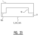
- FIGs 22 , 23 and 24 show different variants of the placing of batteries 5, 205, 305 in main frame 1.
- the battery can for instance be received in a receiving space 18 in main frame 1.
- the dimensions of receiving space 18 in main frame 1 correspond to the dimensions of the battery 5, 205, 305 to be accommodated.
- Shown in figure 23 is a battery 5, 205, 305 which is provided with an edge part 51 which in connected situation abuts against the underside 18b of main frame 1.
- Shown in figure 24 is a construction wherein battery 5, 205, 305 is situated on the one side of main frame 1 while several other components, such as combustion engine 10, coupling 19, generator 9 and fuel cell 11, are located on the other side.
- the coupling of charger 20 is arranged more centrally.
Landscapes
- Engineering & Computer Science (AREA)
- Mining & Mineral Resources (AREA)
- Civil Engineering (AREA)
- General Engineering & Computer Science (AREA)
- Structural Engineering (AREA)
- Mechanical Engineering (AREA)
- Combustion & Propulsion (AREA)
- Transportation (AREA)
- Chemical & Material Sciences (AREA)
- Power Engineering (AREA)
- Electric Propulsion And Braking For Vehicles (AREA)
- Arrangement Or Mounting Of Propulsion Units For Vehicles (AREA)
- Hybrid Electric Vehicles (AREA)
Description
- The present invention relates to a mobile apparatus with an operating arm, such as for instance tractors, excavators, wheel loaders, arm mowers, rotating telescopic cranes, compact trucks with a crane, or combinations thereof. The invention relates more specifically to a mobile apparatus comprising a main frame, an operating arm connected to the main frame, drive means configured to drive displacing means of the mobile apparatus, such as one or more wheels and/or one or more caterpillar tracks, drive means configured to drive the operating arm and a control system, connected to operating instruments for a driver, for controlling the drive means.
- Excavators are known which have only a main frame or a rotatable sub-frame and telescopic cranes on a rotatable sub-frame. Both types of machine can be provided with motor(s) for the drive which are placed in the main frame or in the rotatable sub-frame, wherein a combustion engine provides for driving of a hydraulic pump. These one or more pump(s) provide(s) the operating arm and components thereof with energy.
-
EP 2578756A1 of Hitachi describes a compact excavator equipped with a parallel hybrid drive. The same type of hybrid system, wherein a hydraulic drive drives the wheels of a mobile work platform, is described inWO2008/107685 in the name of Niftylift Limited. -
EP 2551163 in the name of Hitachi Construction Machinery describes so-called hybrid wheel loaders or loading shovels. Such a solution has a main frame in or on which all components are mounted. -
EP 1 199 411 - Agricultural tractors are known with electric drive of the wheels and power takeoff shafts, such as for instance the electric Rigitrac and the John Deere 7030 Series E-Premium.
GB2493961 - Stated in
NL1035694 - Also known as are electrically driven passenger vehicles as such, such as the Tesla Model S and Model X, Nissan Leaf or BMW i3, which are driven purely electrically. There are also serial hybrid or parallel hybrid vehicles. Examples hereof are the Toyota Prius, Honda Civic Hybrid, the Ford Escape Hybrid and so on. So-called range extenders are also being used more often in the automobile industry. This form uses a small combustion engine to charge the battery. These vehicles can also be charged from a mains electricity supply or other power supply, such as solar panels or quick chargers. Examples hereof are the Chevrolet Volt Plug-in, Fisker Karma, BMW i3 or BMW i8 plug-in with range extender. These vehicles have an electrical and battery system optimized in respect of component architecture, efficiency, cooling, and having a low centre of gravity. These components are constructed in large numbers, making them very well-tested and optimized systems and relatively inexpensive.
- Battery packs, and particularly the cooling, heating and conditioning thereof, are shown in
US 2011/0174556 A1 ,US 2012/0222833 A1 ,US 2013/0074525 A1 andUS 2013/0153317 in the name of Tesla Motors.WO 2013/066926 A1 in the name of Brammo Inc. describes batteries for electric motorbikes. Building or connecting such a battery system into or to a vehicle is shown inUS 2011/0174556 A1 in the name of Tesla Motors and inWO 2012/160407 A1 in the name of Better Place GmbH. - The above stated optimization and design detail of electric driving in the vehicle prior art relates to machines, vehicles or motorbikes with one function, either a function as tractor, as excavator, as loading shovel or as vehicle for transporting persons and/or freight.
- It is therefore an object of the present invention, among others, to provide an energy-efficient, versatile and/or improved mobile apparatus. This object is achieved, among others, by a mobile apparatus as according to
claim 1. - The mobile apparatus of the type stated in the preamble has the special feature that the drive means for the displacing means comprise an electric motor such that the drive of the displacing means is substantially electrical.
- The present invention is distinguished from the prior art in that it realizes a solely electrical drive for driving one or more wheels or one or more caterpillar tracks for displacing the frame. The drive and movement of an operating arm can be effected using hydraulics, wherein a hydraulic pump can be provided with a drive embodied as electric motor. The movable operating arm can for instance operate in a folded-out articulated position and operate as folded-together single lifting arm. A further embodiment makes use of electrical energy to firstly drive an implement on the operating arm and secondly to possibly also bring about the operating arm movements with electrical energy, optionally via hydraulics.
- It is particularly advantageous for multiple consuming devices, i.e. actuators for supplying energy, to be driven by more than one electric motor. This also makes it more complex, since multiple consuming devices may require cooling and control management. This can be controlled by the control system, for instance by a computer or computing unit.
- It is moreover advantageous for an energy-efficient electrical system to be provided which is optimized so as to reduce the energy demand required by the different drives. In
EP 1199411 of Kobelco Construction Machinery Co. as stated above the driving for the caterpillar tracks takes place by means of hydraulics. The efficiency thereof is never greater than 80%. The efficiency of an electric drive for displacement/travel can be between 90% and 95%. As the travelled distances become greater and the speed increases, the energy saving becomes proportionally greater. Another advantage of electrical driving - and so the present invention - is that from standstill it is possible to accelerate up to about 150 km/h in continuously variable manner with large moment of torque and without changing gear. This is not possible mechanically or hydraulically. - The one or more electric motors for the tyres or caterpillar tracks can, if built in, also provide for recovery of braking energy, which in turn provides energy savings. More specifically, at least one electric motor for the drive of the displacing means then has a braking energy recovery system configured to return energy to an energy storage unit. It is also advantageous for the braking system and/or the steering system of the mobile apparatus to be driven directly or indirectly or be partially actuated by a separate electric motor or an electric actuator, which is preferably controlled by the control system.
- Electric travel is also possible while an implement connected to the main frame or to the operating arm is switched on. This increases the comfort of the driver. The accuracy of positioning of such a machine with an operating arm in compact spaces is also better than with a hydraulic or mechanical drive.
- According to a further preferred embodiment, the mobile apparatus is configured for the use of implements on the operating arm. The mobile apparatus preferably also comprises a lifting device which can also be employed as stabilizing device. The operating arm and/or the lifting device can comprise electric actuators for driving thereof, wherein the actuators are configured to be controlled with the control system.
- According to a further preferred embodiment, at least one lifting device is therefore arranged on the main frame for the purpose of coupling implements, or a stabilizing device is arranged, wherein the lifting device is provided with a drive embodied as electric motor and configured to be controlled via the control system. The lifting device can comprise a three-point lifting device for coupling of implements or a stabilizing device.
- It is also possible to couple implements to the main frame via the lifting device. These implements require the availability of a high peak capacity, such as in the case of a grass (flail) mower on the operating arm or a wood chipper, or when travelling uphill. This peak capacity is not necessary most of the time, for instance when only travelling over a flat surface or during excavation or loading shovel operations. An implement coupled to the operating arm or an implement on a lifting device on the main frame can be driven electrically by means of energy from either an energy storage unit, a generator or a fuel cell.
- According to the prior art a combustion engine should be able to provide this peak capacity. Such a combustion engine is however large, complex due to the emission-reducing chemical treatment of the exhaust gases, and also expensive. In the case of an electric drive for these applications the more than average demand for motor power is supported more easily by the electric drive because of the large torque. When there is sufficient energy in an energy storage provision, such as a battery, capacitor or other forms of storage, this demand can be met more easily and with a higher efficiency.
- A hydraulic pump for driving an implement on the operating arm or on the main frame cannot be switched off completely when the energy is not being demanded because in the present prior art it is mechanically coupled to a combustion engine. The combustion engine has to run at all times at a minimum stationary rotation speed and also for cooling, power-assisted braking and power-assisted steering. The present invention can optionally control separate electric motors or a single, larger electric motor at a very low power and rotation speed, and thereby consumption, so that only the necessary systems are supplied with energy. An even lower energy consumption is hereby possible, for instance when just travelling without the implement or operating arm being switched on. Another option is to move only the operating arm via a motor and not to use travel drive.
- It is also advantageous for the consuming devices, i.e. the drives, to be of the same type and optionally power, and also to be controlled by the same type of controller and supplied with power by the same type of inverter/converter. This makes it easy to interchange components. It is more specifically advantageous for at least two drives to be formed by two substantially identical electric motors.
- It is also recommended for at least two drives to be formed by two electric motors comprising at least an identical control and identical mounting means for mounting the motors in the mobile unit. At least two controllers for two drives can also be identical for the purpose of the interchangeability and easy replaceability. At least two inverters/converters for the two drives are preferably also identical.
- The present invention is further distinguished by the option of a hybrid solution, also referred to as range extender, for all energy-demanding applications, so as well as for travel/displacement, driving of implements, moving of the arm or a synchronous combination thereof. The invention takes the required peak capacity from the energy storage, for instance a battery or batteries or capacitors, and this is charged by a combustion engine via a generator or a fuel cell system.
- A preferred embodiment of a mobile apparatus according to the invention therefore also comprises a generator which is operatively connected to an energy storage unit and a combustion engine operatively connected to the generator, wherein the combustion engine and generator are configured to supply electrical energy to the energy storage unit.
- For direct supply of electrical energy to the drive, at least one of the drives embodied as electric motor can be operatively connected to a generator which is operatively connected to a combustion engine, wherein the combustion engine and generator are configured to supply electrical energy to the drive.
- In the case of a combustion engine, this can supply energy at an ideal - high-efficiency - rotation speed. An additional advantage of the invention is that less sound is produced by the combustion engine than in the case of an engine of greater power. The required emission treatment of the exhaust gases is less complex and requires less cooling power, whereby the resulting overall difference in efficiency is even more favourable. The range extender can also supply energy directly to a generator, whereby the total peak capacity to the different electric motors or actuators is generated by the combustion engine supplemented with energy from an energy storage unit.
- At least the drive for the displacing means embodied as electric motor can for this purpose be operatively connected to both an energy storage unit and a generator, wherein the electrical energy is supplied to this electric motor by the generator and simultaneously by the energy storage unit.
- A possible embodiment is that the combustion engine is coupled in parallel and mechanically to the generator and for instance also to a hydraulic or air pump. This connection can be fixed (parallel mild hybrid) and the generator thus always co-rotates with the combustion engine and for instance a pump. It can also be connected releasably, for instance by a coupling, whereby the generator becomes a motor and thereby supplies energy from a storage unit to the pump while the combustion engine is switched off, a so-called parallel full-hybrid. In the case of a mechanical connection between generator/motor and a hydraulic or air pump the generator - which is then a motor - can supply energy via a pump. The generator/motor is then supplied with power by an energy storage unit.
- It is possible for this purpose for at least one of the drives embodied as electric motor to also be configured to function as generator, wherein a combustion engine is connected to the electric motor using a connectable and disconnectable coupling.
- Another embodiment is the so-called serial-hybrid, wherein there is no mechanical connection between generator and for instance a pump, but there is always a mechanical connection between combustion engine and generator. It is hereby always possible to supply energy from an energy storage unit to an electrical consuming device without a running combustion engine. It is thus possible to travel - owing to the electrical drive on the displacing means - while, in the case of a combustion engine, this engine is not running.
- It is particularly advantageous for the mobile apparatus to be able to operate or travel purely electrically - and without emission - while the combustion engine is not running. The control system can then be configured to switch off the combustion engine as a response to input of an electrical mode by the driver via the operating instruments. In nature reserves or urban areas and residential areas this is desired more often, and sometimes even required by local authorities. This is also the case for possible leakage of liquids such as hydraulic oil. The more electric motors/consuming devices, the less leakage compared to hydraulic consuming devices.
- In the case of a generator, this can be driven by a combustion engine. This can be a diesel engine, a petrol engine, a gas engine or other type of engine.
- It is particularly advantageous for the control system to be a bus system. Maximum use can hereby be made of the available energy in optionally more than one energy storage unit at different locations. In the case of an implement on the main frame demanding energy at the same time as an implement on the operating arm, the energy demand can be regulated using this system. The control system or the bus system controls at least one controller for the at least one drive embodied as electric motor. The operating instruments are coupled here to a computing/computer unit, wherein the computing unit is configured to compute the extent to which one - or a combination - of the drives is controlled via the control system or the bus system.
- Another advantage is the architecture of the components, the so-called packaging. The invention makes it geometrically possible to incorporate above stated standard automotive energy storage units, capacitors and battery systems in the frame. It is then advantageous that at least one energy storage unit can be coupled to the main frame via the front, the rear or the side and/or that at least one energy storage unit can be coupled to the main frame via the upper or underside. It is moreover possible that at least one energy storage unit can be coupled for this purpose to the rotatable sub-frame via the rear side of the sub-frame. It is moreover advantageous for at least one energy storage unit to be spring-mounted.
- Particularly advantageous is the use of the mass of the energy storage unit as counterweight in a rotating sub-frame or for the purpose of lowering the centre of gravity of the main frame. The plug-in character is also innovative. The mobile apparatus can also be charged by a standard mains electricity supply or special high-capacity chargers outside the mobile apparatus, whereby the charging time is shortened. This can also be an induction system over it is possible to park or travel. An energy storage unit can for this purpose be charged via a charger by an energy source outside the mobile apparatus. This can also be an energy source which can be carried or pulled along by the mobile apparatus. In such a situation it is advantageous to have the connection of the charger on the rear side of the main frame at the coupling of the pulled energy source.
- The mobile apparatus has a main frame with one or more displacing means, such as one or more tyres or one or more caterpillar tracks or a combination thereof, and preferably having thereon a location for a driver and an operating arm for lifting and displacing loads or coupling implements, such as for excavation work, crane operations, mowing operations, loading shovel operations, or implements for combatting icy conditions, for forestry or for golf course maintenance. In addition to the operating arm, the mobile apparatus preferably also has one or more additional lifting devices to which can be coupled implements such as a wood chipper, a ground cutter, a salt-spreader, a grass mower, a pallet fork, a stabilizer shield. Many other implements for forestry or agriculture, construction or for landscape management can be coupled via a lifting device to the front side or rear side of the main frame. The type of lifting device for coupling an implement can be random, but for instance also the known three-point lifting device.
- . It is the case that the driver can rotate in a location/cab relative to the main frame. This location/cab is arranged on a sub-frame.
- Another embodiment is that a rotatable sub-frame with a workplace or cab for the driver and at least one or more operating arms on the sub-frame is connected to a main frame, usually via a vertical or substantially vertical shaft. A preferred embodiment of a mobile apparatus more specifically comprises a sub-frame arranged rotatably relative to the main frame, wherein the rotatable sub-frame comprises the operating instruments for the driver. The sub-frame can rotate partially or completely through 360 degrees without limit.
- In order to limit the transfer of energy it is advantageous for the drive and the energy storage unit of an actuator which is arranged in a frame to also be arranged in that frame. As stated, the operating arm is preferably arranged on the sub-frame, wherein the drive of the operating arm is arranged in the sub-frame. An energy storage unit in the sub-frame can then be arranged as counterweight. The energy storage unit for the drive of the operating arm is more preferably arranged in or on the sub-frame.
- All embodiments have in common that the displacing means are driven by one or more electric motors. Electrical energy for these and other components comes for instance from an energy storage unit such as a battery or a capacitor. The energy can also come from a generator or a fuel cell. These components can be positioned in the main frame or in or on a rotating location of a driver or in or on a rotating sub-frame. It can also be the case in an embodiment that some of the components are positioned in the main frame, some at the cab or some in or on the rotating sub-frame, or another combination.
- Since the displacing means are arranged on the main frame, the drive of the displacing means is also arranged in or on the main frame. At least one energy storage unit for supplying energy to the at least one electric motor for the displacing means is arranged in or on the main frame.
- The energy storage units can however also be distributed over the frames. It is for instance possible for at least one energy storage unit to be positioned in the main frame and at least one energy storage unit in the sub-frame, wherein they are connected to a drive embodied as electric motor so that the electric motor can be supplied with power from a combination of energy storage units. In the case there is insufficient capacity in the one storage, the supply of energy can still take place from the other energy storage unit.
- The distribution of other components is also flexible. It is possible for at least one generator or at least one fuel cell system to be placed in the main frame. It is also possible for at least one generator or at least one fuel cell system to be placed in the rotatable sub-frame.
- Different forms of energy are distinguished in the mobile apparatus. Electrical energy can come from an energy storage unit or from a generator or from a fuel cell. Hydraulic energy for instance comes from a hydraulic pump. Pneumatic energy will then come from a compressor or pump. A mechanical energy comes for instance from a rotating shaft. These possible media, and thus energy flows, provide for the movement of an operating arm, a lifting device, a power takeoff shaft or implement or a part of an implement on a lifting device or an implement on an operating arm, so-called consuming devices.
- A preferred embodiment comprises for this purpose a plurality of drives for driving actuators, i.e. consuming devices, for supplying energy, such as a hydraulic pump, a pneumatic pump or a rotating shaft, wherein each of the drives is embodied as electric motor. The different consuming devices can then be controlled in simple manner when each drive is configured to be controlled via the control system.
- A mobile apparatus preferably comprises at least two energy storage units for supplying energy to at least two of the drives. Each of the drives is however more preferably provided with its own energy storage unit. The transport of electrical energy through the mobile apparatus is hereby limited.
- An embodiment always has electric driving for one or more tyres or one or more caterpillar tracks on the main frame. It is possible here for the drive means for the displacing means, embodied as at least an electric motor, to directly drive the displacing means. Each wheel, or a number of wheels, can then be provided with its own electric motor with suitable control via the control system. It is however also possible for at least one of the drives, including that for the displacing means, to be provided with a suitable transmission.
- A further embodiment is a takeoff shaft (also) driven directly by a combustion engine or by a hydraulic motor. A lifting device can serve as stabilizing device so as to obtain a more stable mobile apparatus during loading shovel or excavation work or crane operations.
- It is characteristic for the driver to control the driving of one or more consuming devices or drives via the control system via operating instruments at the driver location.
- A consuming device can be an electric motor for the drive of the displacing means, an electric motor for driving a power takeoff shaft, a hydraulic valve for controlling an operating arm, an electric motor for a hydraulic pump, an electric motor for controlling the rotation of a sub-frame or an implement on the operating arm or on a lifting device.
- It is possible that the rotation of the sub-frame relative to the main frame is driven by an electric motor controlled by the operating instruments via the control system. More specifically, the sub-frame is preferably rotatable relative to the main frame by means of an electric motor configured to be controlled by the operating instruments via the control system.
- The skilled person will appreciate that operating instruments on the sub-frame can be a computer screen or display or a panel or a number of buttons, or can be one or more joysticks or a combination thereof which transmits the commands entered by the driver, optionally via a computing unit/computer, as signals to the control system.
- Components which transmit the different commands from the control system to for instance an electric motor or a hydraulic or pneumatic valve or an implement on the lifting device are for instance so-called controllers or I/O units or interfaces or ECUs, which control and convert the command signals via different components into mechanical, hydraulic, electrical, pneumatic energy or combinations thereof, but at least electrical energy to the electric motors for displacing of the mobile apparatus.
- Components which convert alternating current into direct current and vice versa can be so-called inverters or converters. The energy in a storage unit is usually of the direct current type. Most consuming devices in the form of electric motors or actuators are often of the alternating current type.
- In a further embodiment these consuming devices also have sensors, and the information therefrom is transmitted via the control system to a computing unit. This can also be the status of an energy storage unit, of a generator, of a combustion engine or of a fuel cell. The input is used to calculate for instance the available capacity of the generator or of the energy storage unit, the power required for a consuming device, torque required for a consuming device, required cooling temperature of a consuming device, required range in kilometres or consumption per unit time and associated consumption in a determined period of time. At least one of the drives is provided with a sensor for detecting the status of the drive, wherein the computing unit is configured to control the drive on the basis of the input of the sensor and the operating instruments.
- An embodiment is possible wherein an energy storage unit and a generator or a fuel cell both supply energy to one or more consuming devices.
- According to a preferred embodiment, it is possible for an energy storage unit to provide at least an electric motor with power for the drive of the displacing means. This storage unit can be positioned in or on the main frame or outside this main frame. This energy storage unit can thus also be in or at a rotating location for a driver or in or on a rotating sub-frame.
- According to a further preferred embodiment, multiple consuming devices are provided with power by one and the same energy storage unit. It is moreover possible that there is more than one energy storage unit and that these provide a consuming device separately with electricity. An alternative is that there are more energy storage units which are connected in order to provide one or more consuming devices with energy.
- According to different embodiments, electrical energy can be transferred between the rotatable sub-frame and the main frame and vice versa by a so-called slip ring or rotary joint. According to a further preferred embodiment, the mobile apparatus more specifically comprises for this purpose a rotary joint (slip ring) between the main frame and the rotatable sub-frame configured to feed electrical energy for the at least one drive between the main frame and the rotatable sub-frame. The transmission of the command signals between main frame and sub-frame can also take place here via a slip ring or rotary joint with for instance slide contacts or contacts with a liquid metal.
- A further embodiment provides for transfer of the command signals between main frame and sub-frame via a contactless wireless connection, such as for instance radiographically or via Bluetooth.
- An embodiment has the control and feedback via the control system of the energy source, such as for instance combustion engine or other type of motor or energy source.
- An embodiment is possible wherein the driver enters commands via a remote control system, wherein these are transferred via an antenna and data transmitter to the control system for the purpose of controlling the mobile apparatus, and particularly controlling one or more electric motors for driving one or more tyres or one or more caterpillar tracks. The antenna or data transmitter can be placed here in the sub-frame or in the main frame.
- A further embodiment provides for control of more than one energy flow to a lifting device. A flow of energy thus provides for the up and downward movement of the lifting device and another flow of energy can thus provide for the adjustment of the angle of the lifting device, such as for instance adjustment of the angle of a three-point lifting device or the angle of a quick change system on the lifting device.
- There can be different embodiments of a control system. For instance a Can-Bus system of different protocols such as J1939, Flex Ray, Isobus or other types. This can also be a glass fibre system. A control system is also understood to mean that electrical or digital signals are transmitted from a component to another component in order to transfer data whereby a consuming device is controlled or feedback data return from one component to another component. A computing unit or computer unit or a processor is a component which can transmit and receive command signals from for instance a controller, an inverter or converter, an electric motor or an electric actuator.
- Another further embodiment provides for entry of a priority by the driver via the operating instruments. Priority can be given to the change in the travel speed or the travel power of the whole mobile apparatus, or priority to the implement in a lifting device on the main frame, or priority to an implement on the operating arm. The computing unit provides for transmission of the energy requirement to the different components via the control system. It is then more specifically advantageous for the control system to be configured to distribute the available electrical energy over the plurality of drives on the basis of priorities of the drives entered by the driver with the operating instruments.
- The driver can choose the priority setting subject to the working mode. In the case of travel alone, the priority lies with the control of one or more electric motors for the displacing means. In the case of excavation work or crane operations the priority lies with movement of the operating arm. In the case of loading shovel operations it lies with both the arm and the travel. During functioning as tractor it lies with both the power takeoff shaft and the travel. And when an implement is employed on the arm and an implement on the lifting device it lies with these, and less with the travel. The computing unit determines which energy goes to which consuming device and also determines whether the generator or the fuel cell is switched on.
- In the case of silent mode or purely electrical mode, so without combustion engine running, the computing unit can also determine that the consuming devices are allowed less energy in order to increase the operating time. This energy management can for instance also be used to reduce consumption. The driver can preferably set an energy-saving mode.
- As noted above, the electric motors of the different consuming devices are preferably identical. This is also the case for the inverters/converters and the controllers or I/O or ECUs. It is possible that 75% of these components are identical. An example is for instance that an electric motor for the drive of the displacing means and an electric motor for a power takeoff shaft or an electric motor for a pump are identical. This can also be the case for the controllers and inverters thereof.
- There are possibilities for a gearbox, planetary system, a differential or other type of transmission to be connected between an electric motor as consuming device and a takeoff shaft, pump, tyres or caterpillar tracks.
- The operating instruments can also reverse the direction of rotation of an electric motor on a power takeoff shaft in simple manner for the correct combination of implement and the travel direction of the mobile apparatus. The direction of rotation of the electric motor for driving at least a power takeoff shaft can for this purpose be adjustable, depending for instance on a chosen travel direction of the mobile apparatus and/or the coupled implement.
- Energy storage units can also be spring-mounted and mounted for damping in order to ensure that an off-road application is suitable for the energy storage unit such as battery or capacitor. At least one energy storage unit preferably has a cooling or a heating. The cooling of the at least one energy storage unit can take place by means of a liquid or water, or by means of air. An external pump or fan can be used for this purpose.
- The above stated and other advantageous features and objects of the invention will become more apparent, and the invention better understood, on the basis of the following detailed description when read in combination with the accompanying drawings, in which:
-
figures 1-5 show schematic side and front views of different embodiments of the mobile apparatus; and -
figures 6-16 show block diagrams of different embodiments of the mobile apparatus according to the invention; and -
figures 17-24 show schematic side and rear views of different embodiments of the invention. -
Figure 1 shows amobile apparatus 1000 provided withmain frame 1 on whichwheels 4 are arranged. Alocation 6 for the driver in the form of a cab is arranged onmain frame 1.Cab 6 is rotatable to limited extent relative tomain frame 1. Also arranged onmain frame 1 is anoperating arm 100 with an implement 101.Main frame 1 is moreover provided with alifting device 200 to which additional implements (not shown) can be coupled. - In the embodiment of
figure 2 caterpillar tracks 4 are arranged on the main frame as displacing means instead of wheels.Figure 3 shows a variant of a mobile apparatus provided with caterpillar tracks. - The embodiment in
figure 4 is provided with asub-frame 2 which is infinitely rotatable relative tomain frame 1 by means ofslip ring 400. The apparatus can comprise for this purpose an electric motor with suitable control, as will be described in more detail below.Cab 6 andoperating arm 100 with implement 101 are arranged onsub-frame 2 and can thereby also rotate infinitely relative tomain frame 1.Main frame 1 is also provided in this embodiment with apower takeoff shaft 204. -
Figure 5 shows a front view of amobile apparatus 1000, whereinsub-frame 2 is rotated relative tomain frame 1. In thisembodiment operating arm 100 is an articulated operating arm provided with an implement 101 for excavating. - The construction of the different components of a mobile apparatus is described schematically in more detail in the following figures. It will be apparent that, when reference is for instance made to
wheels 4 in the context of these figures, these can equally well be replaced by the caterpillar tracks as shown infigures 2-4 . - With reference to
figure 6 , the driving of displacing means 4, in this variant in the form ofwheels 4, takes place using anelectric motor 3.Motor 3 drives amain drive shaft 41 which driveswheels 4 via suitable differentials and driveshafts 42.Electric motor 3 is electrically coupled to an energy storage in the form of a battery 5. In this embodiment battery 5 is coupled via aninverter 501 toelectric motor 3. Control ofelectric motor 3 takes place via acommand system 8. The driver or user of the mobile unit can give instructions tocommand system 8, for instance for the control of the drive means of displacing means 4, viaoperating instruments 7. In thisembodiment operating instruments 7 are arranged in the cab of a mobile apparatus.Command system 8 can optionally be coupled via acontroller 500 toelectric motor 3, wherein the controller is configured to convert the control signals ofcommand system 8 to suitable control signals forelectric motor 3. - The embodiment as shown in
figure 7 differs from that offigure 6 in respect of the drive of displacingmeans 4. In this embodiment displacing means 4 are driven directly by anelectric motor 3.Electric motor 3 is more specifically arranged directly on the shaft of awheel 4. Although only onewheel 4 is provided with a drive in this embodiment, it will be apparent that each of the wheels can be provided with such a drive in the form of anelectric motor 3, wherein each of these motors is connected to a or the battery 5 andcommand system 8, optionally viacontrollers 500, for control thereof. - Shown for instance in
figure 8 is that a rear electric motor 3a is provided which drivesrear shaft 41a, which in turn drives thedrive shafts 42a ofrear wheels 4 via a suitable differential. The control of electric motor 3a again takes place viacontroller 500 andcommand system 8. Provided on the front side is a secondelectric motor 3b which drivesfront wheels 4 viafront shaft 41b and driveshafts 42b. The frontelectric motor 3b is also coupled via itsown controller 500 to commandsystem 8 for the control thereof. The twomotors 3a, 3b are coupled viainverters 501 to the same battery 5. - Provided in the embodiment of
figure 9 for charging battery 5 is acombustion engine 10 which is coupled via acoupling 19 to agenerator 9. It is possible for coupling 19 to be integrated intogenerator 9 orcombustion engine 10.Generator 9 is coupled to battery 5 via aninverter 501. Since in thisvariant combustion engine 10 serves only for charging battery 5 and not for driving of for instance the displacing means, the combustion engine can run at an ideal, high-efficiency rotation speed, whereingenerator 9 converts this movement into electrical energy which is supplied viainverter 501 to battery 5. - A variant is shown in
figure 10 . In thisembodiment generator 9 is also coupled via theoptional inverter 501 toelectric motor 3. This makes it possible for the electricity generated bycombustion engine 10 to be supplied directly, i.e. without interposing battery 5, toelectric motor 3. -
Figure 11 shows other means for charging battery 5 which can be used as alternative to or in combination with the combustion engine. Battery 5 can thus be charged using afuel cell 11 and/or battery 5 can be charged using acharger 12 which can be coupled with areleasable connector 13a to anexternal energy source 13, for instance a (high-voltage) wall socket in a garage. -
Figure 12 shows an embodiment provided with apower takeoff shaft 204. Thispower takeoff shaft 204 is driven by anelectric motor 203.Electric motor 203 forpower takeoff shaft 204 is in turn coupled via acontroller 500 to commandsystem 8 for the control of thepower takeoff shaft 204. The electricity forelectric motor 203 forpower takeoff shaft 204 is again supplied by battery 5 via aninverter 501. The same battery 5 also supplies energy toelectric motor 3 for driving thewheels 4. It is once again possible in this variant for battery 5 to be provided with energy bycombustion engine 10 via a generator 9 (figure 13 ) and/or using a fuel cell 11 (figure 14 ). -
Figure 15 shows the drive ofpower takeoff shaft 204 in isolation. In this embodimentelectric motor 203 obtains energy via aninverter 501 coupled to agenerator 9.Generator 9 here supplies electrical energy directly toelectric motor 203.Generator 9 can be driven by a combustion engine (not shown). It is also possible forelectric motor 203 to obtain energy directly from afuel cell 11, seefigure 16 . -
Figure 17 shows ahydraulic pump 300, for instance for driving thehydraulic operating arm 100.Hydraulic pump 300 is situated in this embodiment inmain frame 1 and is connected via agenerator 9 andcoupling 19 to acombustion engine 10.Combustion engine 10 can here drivehydraulic pump 300 directly, wherein electrical energy is also generated bygenerator 9. This latter is connected for this purpose to abattery 305. - In an embodiment it is however also possible that
generator 9 can also serve as electric motor, for instance in the case thatcombustion engine 10 is switched off.Coupling 19 can for this purpose disconnectcombustion engine 10 from thegenerator 9 acting as electric motor.Generator 9 acting as electric motor obtains energy from abattery 305 coupled thereto. - In the variant of
figure 18 the combination ofcombustion engine 10,coupling 19,generator 9 andhydraulic pump 300 is arranged inrotatable sub-frame 2. This is particularly advantageous when operatingarm 100 is also arranged onrotatable sub-frame 2. Also shown is thatmain frame 1 is provided with acoupling 20 for a charger. This is located on the rear side ofmain frame 1 so that it can be easily coupled to a power supply, which can for instance be placed in a trailer behind the mobile apparatus. -
Figure 19 shows that a singlehydraulic pump 300 can be connected to a plurality ofhydraulic valves 301 and 301' using suitablehydraulic conduits 306. Onevalve 301 is for instance situated in the main frame for coupling to an implement, while a second valve 301', for instance for an implement 101 on operatingarm 100 or for operatingarm 100 itself, is situated insub-frame 2. - The hydraulic conduit is then carried from
hydraulic pump 300 inmain frame 1 throughslip ring 400 to valve 301' insub-frame 2. It will be apparent that a plurality of valves can be provided. - Solely electrical driving of a
hydraulic pump 300 is however also possible. An example hereof is shown infigure 20 . Ahydraulic pump 300 insub-frame 2 is coupled here to anelectric motor 303, which is in turn coupled to a suitable battery which is preferably also situated insub-frame 2.Hydraulic pump 300 is coupled to avalve 301 arranged insub-frame 2. - It will be apparent that each of the components for controlling, such as
electric motors valves 301, 301', are coupled in these embodiments to commandsystem 8, for instance usingsuitable controllers 500 as also shown in the previous embodiments. The different components, forinstance drive 3 ofwheels 4, drive 203 of a power takeoff shaft 204 (figure 12 ) and drive 303 ofhydraulic pump 300, can then be controlled using operating instruments 7 (see for instancefigure 6 ). It is then particularly advantageous for the different components for controlling to be provided with sensors for measuring the different operating parameters, such as for instance temperature, (hydraulic) pressure, (relative) positions of drive shafts, and so on. Thedifferent controllers 500 can then transmit these measurements to commandsystem 8 so that the components can be controlled with feedback. - As stated, electric motors can be arranged both in
main frame 1 and insub-frame 2 for the purpose of driving different components.Batteries 5, 205, 305 which supply the energy for these electric motors can also be arranged in bothmain frame 1 andsub-frame 2.Figure 21 shows for instance that abattery 5, 205, 305 is arranged on the underside ofmain frame 1, while asecond battery 5, 205, 305 is arranged on the rear side ofsub-frame 2. Thisbattery 5, 205, 305 then at the same time serves as counterweight. -
Figures 22 ,23 and24 show different variants of the placing ofbatteries 5, 205, 305 inmain frame 1. In the embodiment offigure 22 the battery can for instance be received in a receivingspace 18 inmain frame 1. The dimensions of receivingspace 18 inmain frame 1 correspond to the dimensions of thebattery 5, 205, 305 to be accommodated. Shown infigure 23 is abattery 5, 205, 305 which is provided with anedge part 51 which in connected situation abuts against the underside 18b ofmain frame 1. Shown infigure 24 is a construction whereinbattery 5, 205, 305 is situated on the one side ofmain frame 1 while several other components, such ascombustion engine 10,coupling 19,generator 9 andfuel cell 11, are located on the other side. The coupling ofcharger 20 is arranged more centrally. -
- 1. main frame
- 2. sub-frame
- 3. electric motor for driving displacement
- 4. tyre(s) or caterpillar track(s)
- 5. energy storage
- 6. location driver
- 7. operating instruments
- 8. command system
- 9. generator
- 10. combustion engine
- 11. fuel cell
- 12. charger
- 13. energy source outside mobile apparatus
- 19. coupling
- 20. coupling of charger
- 100. operating arm
- 101. implement on operating arm
- 200. lifting device
- 201. implement on lifting device
- 202. stabilizing device
- 203. electric motor for drive of power takeoff shaft
- 204. power takeoff shaft
- 205. energy storage
- 300. hydraulic pump
- 301. hydraulic valve
- 303. electric motor for hydraulic pump
- 305. energy storage
- 400. rotary joint/slip ring
- 500. controller or ECU or I/O unit
- 501. inverter or a converter
- The present invention is not limited to the shown embodiments but also extends to other embodiments falling within the scope of the appended claims.
Claims (15)
- Mobile apparatus comprising a main frame with displacing means (1), a sub-frame arranged rotatably relative to the main frame, wherein the rotatable sub-frame comprises operating instruments for a driver, an operating arm (100) connected to the sub- frame, a first drive means configured to drive the displacing means (4), a second drive means configured to drive the operating arm (100), and a control system (8), connected to the operating instruments (7), for controlling the first and second drive means, wherein the first drive means comprises at least one electric motor such that the drive of the displacing means is substantially electrical; wherein the control system comprises a bus system; wherein the first drive means is solely electrical; said mobile apparatus also comprising at least one energy storage unit (5 or 205 or 305), such as a battery or capacitor, for storing and supplying electrical energy to the at least one electric motor (3); characterized in that the displacing means and the first drive are arranged in or on the main frame (1) and the at least one energy storage unit (5 or 205 or 305) for supplying energy to the at least one electric motor (3) for the displacing means is arranged in or on the main frame (1); wherein the operating instruments (7) are coupled to a computing/computer unit (14), wherein the computing unit is configured to compute the extent to which one - or a combination - of the drives (3, 101, 201, 203, 303, 401) is controlled via the control system (8) or the bus system, wherein at least one of the drives is provided with a sensor for detecting the status of the drive, wherein the computing unit is configured to control the drive on the basis of the input of the sensor and the operating instruments.
- Mobile apparatus as claimed in any of the foregoing claims, wherein the second drive means for the operating arm (100) comprise an electric motor (3).
- Mobile apparatus as claimed in any of the foregoing claims, wherein at least one energy storage unit is coupled to the main frame via any one of the following: the front, the rear or the side of the main frame, the upper or underside of the main frame, or received in a receiving space (18) in the main frame.
- Mobile apparatus as claimed in any of the foregoing claims, also comprising a plurality of third drives for driving actuators for supplying energy, such as a hydraulic pump, a pneumatic pump, a compressor, or a rotating shaft, wherein each of the third drives is embodied as an electric motor, wherein each third drive is configured to be controlled via the control system (8).
- Mobile apparatus as claimed in claim 1, wherein the second drive means of the operating arm (100) is arranged in the sub-frame (2) or in the main frame; and/or wherein an energy storage unit for the second drive is arranged in or on the sub-frame or the main frame.
- Mobile apparatus as claimed in any one of the foregoing claims, also comprising a generator (9) which is operatively connected to the at least one energy storage unit and a combustion engine (10) operatively connected to the generator (9), placed in or on the sub-frame or in the main frame, wherein the combustion engine (10) and generator (9) are configured to supply electrical energy to the at least one energy storage unit (5, 205, 305).
- Mobile apparatus as claimed in any of the foregoing claims, optionally in combination with claim 4, wherein at least one of the first drive means, the second drive, and the third drives is embodied as electric motor (3, 203, 303) and is also configured to function as generator (9), wherein a combustion engine (10) is connected to the electric motor (3, 203, 303) using a connectable and disconnectable coupling (19).
- Mobile apparatus as claimed in any one of the foregoing claims, wherein the energy is supplied to the at least one energy storage unit (5, 205, 305) by a fuel cell (11) placed in or on the sub-frame or in the main frame.
- Mobile apparatus as claimed in any of the foregoing claims, wherein a power take-off shaft (204) configured to drive implements (201) is arranged on the main frame (1), wherein the power take-off shaft (204) is provided with a drive embodied as at least one electric motor (3) and configured to be controlled via the control system (8); wherein the at least one electric motor (203) for driving at least one power take-off shaft (204) is provided with energy from at least one energy storage unit (5, 205, 305), a generator (9), a fuel cell, (11) or a combination thereof; wherein optionally the control system is configured to adjust the direction of rotation of the at least one electric motor for driving the power take-off shaft, depending for instance on a chosen travel direction of the mobile apparatus and/or the coupled implement, wherein optionally the electric motor (203) for driving the power take-off shaft (204) is provided with energy from at least one energy storage unit (5, 205, 305) which is the same at least one energy storage unit for supplying energy to the electric motor (3) for the first drive of the displacing means.
- Mobile apparatus as claimed in any of the foregoing claims, also comprising a hydraulic pump (300) configured to supply hydraulic energy, wherein the hydraulic pump (300) is provided with a drive embodied as an electric motor (203) and configured to be controlled via the control system (8); wherein optionally the electric motor (203) of the hydraulic pump (300) can function as a generator (9); optionally also comprising a combustion engine (10) which is connected to the generator (9) using a connectable and disconnectable coupling (19).
- Mobile apparatus as claimed in any one of the foregoing claims, wherein the at least one energy storage unit (5, 205, 305) for supplying energy to the at least one electric motor (3) for the displacing means is positioned externally outside the main frame (1); and/or wherein the at least one of the energy storage units comprises any one or more of the following: a battery; a capacitor.
- Mobile apparatus as claimed in any of the foregoing claims, wherein the operating arm (100) and/or a lifting device (200) comprises electric actuators for driving thereof, wherein the actuators are configured to be controlled with the control system (8); wherein optionally at least one implement (101) coupled to the operating arm (100) or an implement (201) on the at least one lifting device (200) on the main frame is driven electrically by energy from either an energy storage unit (5, 205, 305), a generator (9) or a fuel cell (11).
- Mobile apparatus as claimed in any of the foregoing claims, characterized in that the at least one electric motor (3) for the first drive of the displacing means has a braking energy recovery system configured to return energy to the at least one energy storage unit (5, 205, 305).
- Mobile apparatus as claimed in any of the foregoing claims, characterized in that the first drive comprises two electric motors, preferably two substantially identical electric motors, with optionally two substantially identical controllers, with optionally two substantially identical inverters/converters, with optionally two substantially identical mounting means.
- Mobile apparatus as claimed in any of the foregoing claims, characterized in that the at least one energy storage unit (5, 205, 305) has a cooling or a heating; and/or that the at least one energy storage unit is spring-mounted and mounted for damping.
Applications Claiming Priority (2)
| Application Number | Priority Date | Filing Date | Title |
|---|---|---|---|
| NL2011596A NL2011596C2 (en) | 2013-10-11 | 2013-10-11 | ELECTRIC DRIVE OF MOBILE DEVICE. |
| PCT/NL2014/050689 WO2015053618A1 (en) | 2013-10-11 | 2014-10-06 | Electric drive of mobile apparatus |
Publications (3)
| Publication Number | Publication Date |
|---|---|
| EP3055152A1 EP3055152A1 (en) | 2016-08-17 |
| EP3055152B1 EP3055152B1 (en) | 2021-05-05 |
| EP3055152B2 true EP3055152B2 (en) | 2024-07-31 |
Family
ID=50031457
Family Applications (1)
| Application Number | Title | Priority Date | Filing Date |
|---|---|---|---|
| EP14790764.6A Active EP3055152B2 (en) | 2013-10-11 | 2014-10-06 | Electric drive of mobile apparatus |
Country Status (6)
| Country | Link |
|---|---|
| US (2) | US9845587B2 (en) |
| EP (1) | EP3055152B2 (en) |
| CN (1) | CN105813874B (en) |
| CA (1) | CA2963055A1 (en) |
| NL (1) | NL2011596C2 (en) |
| WO (1) | WO2015053618A1 (en) |
Families Citing this family (26)
| Publication number | Priority date | Publication date | Assignee | Title |
|---|---|---|---|---|
| NL2011596C2 (en) * | 2013-10-11 | 2015-04-14 | Hudson Bay Holding B V | ELECTRIC DRIVE OF MOBILE DEVICE. |
| JP6469381B2 (en) * | 2014-07-28 | 2019-02-13 | 日立建機株式会社 | Hybrid work machine |
| GB2531762A (en) * | 2014-10-29 | 2016-05-04 | Bamford Excavators Ltd | Working machine |
| WO2016182487A1 (en) * | 2015-05-13 | 2016-11-17 | Volvo Construction Equipment Ab | A working machine arranged with means to drive and control a hydraulic pump |
| DK178988B1 (en) * | 2015-12-15 | 2017-07-31 | Staal Ind Ivs | Selvkørende universalkøretøj |
| US10214876B2 (en) * | 2016-06-21 | 2019-02-26 | Kubota Corporation | Work machine |
| CN106759574A (en) * | 2017-03-24 | 2017-05-31 | 林东星 | A kind of multifunctional excavator with folding arm |
| CA3050527A1 (en) * | 2018-07-27 | 2020-01-27 | Manitou Italia S.R.L. | Improved electric telehandler |
| JP7175145B2 (en) * | 2018-09-14 | 2022-11-18 | 株式会社小松製作所 | electric construction machine |
| JP7112371B2 (en) * | 2019-05-14 | 2022-08-03 | 本田技研工業株式会社 | drive unit |
| DE102019003684B4 (en) * | 2019-05-27 | 2024-09-12 | Siempelkamp Maschinen- Und Anlagenbau Gmbh | Device and method for the assembly of material plates |
| EP4051841A4 (en) * | 2019-10-31 | 2024-02-21 | Lovis, LLC | COMPUTER CONTROLLED MOTORIZED PUMP SYSTEM WITH PTO |
| US11685225B2 (en) * | 2019-12-20 | 2023-06-27 | Lovis, Llc | Power takeoff-driven refrigeration |
| DE102019135668A1 (en) * | 2019-12-23 | 2021-06-24 | Wirtgen Gmbh | Self-propelled construction machine and method for controlling a self-propelled construction machine |
| US12180672B2 (en) | 2020-03-02 | 2024-12-31 | Doosan Bobcat North America, Inc. | Electrically powered power machine |
| US11821166B2 (en) * | 2020-07-22 | 2023-11-21 | Caterpillar Underground Mining Pty. Ltd. | Internal support structure for underground battery machines |
| US11725363B2 (en) * | 2020-07-29 | 2023-08-15 | Caterpillar Sarl | Machine configuration and control system enabling interchangeable power sources |
| CA3193813A1 (en) * | 2020-10-05 | 2022-04-14 | Riccardo Magni | Rotary telescopic boom lift |
| JP2022159151A (en) * | 2021-03-31 | 2022-10-17 | ナブテスコ株式会社 | Drive transmission device and construction machine |
| CA3220521A1 (en) | 2021-09-02 | 2023-03-09 | Brent DURKIN | Lift arm arrangements for power machines |
| FR3134399B1 (en) * | 2022-04-12 | 2025-02-28 | Manitou Bf | Method for controlling a fuel cell of a working machine |
| IT202200026844A1 (en) * | 2022-12-27 | 2024-06-27 | Manitou Italia Srl | Energy management system in an electric telehandler. |
| JP2024137048A (en) * | 2023-03-24 | 2024-10-04 | ヤンマーホールディングス株式会社 | Work Machine |
| US12240337B1 (en) | 2024-02-13 | 2025-03-04 | Lovis, Llc | Vehicle auxiliary power system |
| WO2025216968A1 (en) * | 2024-04-07 | 2025-10-16 | Doosan Bobcat North America Inc. | Electric drive motor and inverter on a power machine |
| CN119754372B (en) * | 2025-01-23 | 2025-11-11 | 山东临工工程机械有限公司 | Control method, device and system for braking rotation motor of excavator and excavator |
Citations (13)
| Publication number | Priority date | Publication date | Assignee | Title |
|---|---|---|---|---|
| EP0921094A2 (en) † | 1997-10-24 | 1999-06-09 | Grove U.S. LLC | Aerial work platform with removably attachable support structure for auxiliary power plant |
| US6199307B1 (en) † | 1998-06-01 | 2001-03-13 | Kabushiki Kaisha Kobe Seiko Sho | Battery-powered working machine |
| US20020104239A1 (en) † | 2001-02-06 | 2002-08-08 | Masami Naruse | Hybrid construction equipment |
| GB2385111A (en) † | 2002-02-08 | 2003-08-13 | Bamford Excavators Ltd | Controlling a working arm with links which mimic the working arm geometry |
| FR2839093A1 (en) † | 2002-03-28 | 2003-10-31 | Kubota Kk | WORK VEHICLE WITH WHEELS |
| US6688481B1 (en) † | 1999-10-06 | 2004-02-10 | Terex-Demag Gmbh & Co. Kg | Mobile crane |
| US6990757B2 (en) † | 2003-08-12 | 2006-01-31 | Kubota Corporation | Wheeled work vehicle |
| US7734384B2 (en) † | 2006-09-05 | 2010-06-08 | Ford Global Technologies, Llc | Tuned battery pack damper for a hybrid electric vehicle |
| WO2011128772A1 (en) † | 2010-04-16 | 2011-10-20 | Movimatica Srl | Electrohydraulic hybrid lifting vehicle |
| WO2012088091A1 (en) † | 2010-12-20 | 2012-06-28 | Jlg Industries, Inc. | Work platform with protection against sustained involuntary operation |
| EP2479052A1 (en) † | 2011-01-25 | 2012-07-25 | A&T - Creation Oy | Working machine |
| US20130149095A1 (en) † | 2010-05-31 | 2013-06-13 | Hudson Bay Holding B.V. | Mobile apparatus |
| EP3055152A1 (en) † | 2013-10-11 | 2016-08-17 | Hudson Bay Holding B.V. | Electric drive of mobile apparatus |
Family Cites Families (39)
| Publication number | Priority date | Publication date | Assignee | Title |
|---|---|---|---|---|
| US3040918A (en) * | 1958-06-04 | 1962-06-26 | Eimco Corp | Material handling machine |
| GB8430389D0 (en) * | 1984-12-01 | 1985-01-09 | Bamford Excavators Ltd | Earth moving machine |
| JP4194707B2 (en) * | 1999-03-24 | 2008-12-10 | ザウアーダンフォス・ダイキン株式会社 | Battery powered work machine |
| JP2001011888A (en) | 1999-06-29 | 2001-01-16 | Kobe Steel Ltd | Shovel |
| JP2001012418A (en) * | 1999-06-30 | 2001-01-16 | Kobe Steel Ltd | Hybrid working machine |
| US7350611B2 (en) * | 2004-06-15 | 2008-04-01 | Caterpillar Inc | Method for controlling an electric drive machine |
| US7410437B2 (en) * | 2005-08-31 | 2008-08-12 | Caterpillar Inc. | Planetary drive arrangement |
| US7950481B2 (en) * | 2005-09-29 | 2011-05-31 | Caterpillar Inc. | Electric powertrain for machine |
| US8565946B2 (en) * | 2011-07-01 | 2013-10-22 | General Electric Company | System and method for vehicle control |
| JP2007284873A (en) * | 2006-04-12 | 2007-11-01 | Takeuchi Seisakusho:Kk | Work vehicle |
| WO2007139169A1 (en) * | 2006-06-01 | 2007-12-06 | Takeuchi Mfg. Co., Ltd. | Working vehicle |
| US7658250B2 (en) | 2006-09-29 | 2010-02-09 | Caterpillar Inc. | Energy storage and recovery for a tracked machine |
| GB2447229B (en) | 2007-03-07 | 2011-11-02 | Niftylift Ltd | Mobile work platform with multiple mode drive system |
| US8547055B2 (en) * | 2007-03-14 | 2013-10-01 | Ford Global Technologies, Llc | Method and apparatus to control electric power consumption |
| ITMI20070549A1 (en) * | 2007-03-20 | 2008-09-21 | Giovanni Bertoni | INTEGRATED TRANSFER SYSTEM FOR AN EXCAVATOR |
| NL1035694C2 (en) | 2008-07-14 | 2010-01-18 | Hudson Bay Holding B V | Mobile apparatus for use in e.g. agriculture has automatically movable lifting device that is provided on the main frame and is adapted to be connectable to the agricultural attachment |
| NL2002125C2 (en) * | 2008-07-14 | 2010-01-18 | Hudson Bay Holding B V | Mobile device. |
| JP5185082B2 (en) * | 2008-11-18 | 2013-04-17 | 日立建機株式会社 | Electric hydraulic work machine |
| US8268469B2 (en) | 2009-04-22 | 2012-09-18 | Tesla Motors, Inc. | Battery pack gas exhaust system |
| JP2011078277A (en) * | 2009-10-01 | 2011-04-14 | Hitachi Constr Mach Co Ltd | Electric construction machine |
| JP5228000B2 (en) | 2010-05-26 | 2013-07-03 | 日立建機株式会社 | Hybrid construction machine |
| JP5312400B2 (en) | 2010-05-27 | 2013-10-09 | 日立建機株式会社 | Hybrid wheel loader |
| JP5172898B2 (en) * | 2010-06-15 | 2013-03-27 | 日立建機株式会社 | Electric construction machine |
| US20130218386A1 (en) * | 2010-08-04 | 2013-08-22 | Fisker Automotive, Inc. | Vehicle operation mode systems and methods |
| US8875828B2 (en) | 2010-12-22 | 2014-11-04 | Tesla Motors, Inc. | Vehicle battery pack thermal barrier |
| US9250020B2 (en) | 2011-01-05 | 2016-02-02 | Tesla Motors, Inc. | Active louver system for controlled airflow in a multi-function automotive radiator and condenser system |
| KR101302262B1 (en) * | 2011-03-30 | 2013-09-02 | 가부시끼 가이샤 구보다 | Working car |
| JP5389100B2 (en) * | 2011-04-19 | 2014-01-15 | 日立建機株式会社 | Electric drive for construction machinery |
| US8620536B2 (en) * | 2011-04-29 | 2013-12-31 | Harnischfeger Technologies, Inc. | Controlling a digging operation of an industrial machine |
| WO2012160407A1 (en) | 2011-05-20 | 2012-11-29 | Better Place GmbH | Multi-motor latch assembly |
| CN202357902U (en) * | 2011-08-08 | 2012-08-01 | 武汉理工大学 | Electric vehicle power system with fuel cell as vehicle-mounted extended range type charger |
| GB2493961A (en) | 2011-08-26 | 2013-02-27 | Agco Sa | Power takeoff drive system for an agricultural tractor |
| JP5752531B2 (en) * | 2011-08-31 | 2015-07-22 | 日立建機株式会社 | Construction machinery |
| US10427491B2 (en) | 2011-09-28 | 2019-10-01 | Tesla, Inc. | Thermal management system with heat exchanger blending valve |
| CN103890409A (en) * | 2011-10-20 | 2014-06-25 | 日立建机株式会社 | Hydraulic drive device of power-operated hydraulic operation machine |
| US20130108896A1 (en) | 2011-10-31 | 2013-05-02 | Brammo, Inc. | Methods and apparatus for combined thermal management, temperature sensing, and passive balancing for battery systems in electric vehicles |
| US20140223893A1 (en) * | 2013-02-11 | 2014-08-14 | Caterpillar Inc. | Pilot pump sourced peak shaving for hybrid hydraulic circuits |
| WO2014208568A1 (en) * | 2013-06-26 | 2014-12-31 | 日立建機株式会社 | Hybrid work machine |
| US10379143B2 (en) * | 2014-07-23 | 2019-08-13 | Cummins, Inc. | System and method for improving a battery management and accumulator system |
-
2013
- 2013-10-11 NL NL2011596A patent/NL2011596C2/en not_active IP Right Cessation
-
2014
- 2014-10-06 WO PCT/NL2014/050689 patent/WO2015053618A1/en not_active Ceased
- 2014-10-06 CA CA2963055A patent/CA2963055A1/en not_active Abandoned
- 2014-10-06 CN CN201480067094.2A patent/CN105813874B/en active Active
- 2014-10-06 US US15/027,942 patent/US9845587B2/en active Active
- 2014-10-06 EP EP14790764.6A patent/EP3055152B2/en active Active
-
2017
- 2017-12-04 US US15/830,698 patent/US10669694B2/en active Active
Patent Citations (13)
| Publication number | Priority date | Publication date | Assignee | Title |
|---|---|---|---|---|
| EP0921094A2 (en) † | 1997-10-24 | 1999-06-09 | Grove U.S. LLC | Aerial work platform with removably attachable support structure for auxiliary power plant |
| US6199307B1 (en) † | 1998-06-01 | 2001-03-13 | Kabushiki Kaisha Kobe Seiko Sho | Battery-powered working machine |
| US6688481B1 (en) † | 1999-10-06 | 2004-02-10 | Terex-Demag Gmbh & Co. Kg | Mobile crane |
| US20020104239A1 (en) † | 2001-02-06 | 2002-08-08 | Masami Naruse | Hybrid construction equipment |
| GB2385111A (en) † | 2002-02-08 | 2003-08-13 | Bamford Excavators Ltd | Controlling a working arm with links which mimic the working arm geometry |
| FR2839093A1 (en) † | 2002-03-28 | 2003-10-31 | Kubota Kk | WORK VEHICLE WITH WHEELS |
| US6990757B2 (en) † | 2003-08-12 | 2006-01-31 | Kubota Corporation | Wheeled work vehicle |
| US7734384B2 (en) † | 2006-09-05 | 2010-06-08 | Ford Global Technologies, Llc | Tuned battery pack damper for a hybrid electric vehicle |
| WO2011128772A1 (en) † | 2010-04-16 | 2011-10-20 | Movimatica Srl | Electrohydraulic hybrid lifting vehicle |
| US20130149095A1 (en) † | 2010-05-31 | 2013-06-13 | Hudson Bay Holding B.V. | Mobile apparatus |
| WO2012088091A1 (en) † | 2010-12-20 | 2012-06-28 | Jlg Industries, Inc. | Work platform with protection against sustained involuntary operation |
| EP2479052A1 (en) † | 2011-01-25 | 2012-07-25 | A&T - Creation Oy | Working machine |
| EP3055152A1 (en) † | 2013-10-11 | 2016-08-17 | Hudson Bay Holding B.V. | Electric drive of mobile apparatus |
Non-Patent Citations (1)
| Title |
|---|
| EUROPEAN AND FRENCH STANDARD NF EN 280, December 2001 (2001-12-01), pages 39 † |
Also Published As
| Publication number | Publication date |
|---|---|
| US10669694B2 (en) | 2020-06-02 |
| CN105813874A (en) | 2016-07-27 |
| EP3055152B1 (en) | 2021-05-05 |
| US20180106017A1 (en) | 2018-04-19 |
| WO2015053618A1 (en) | 2015-04-16 |
| US9845587B2 (en) | 2017-12-19 |
| CA2963055A1 (en) | 2015-04-16 |
| CN105813874B (en) | 2019-12-10 |
| EP3055152A1 (en) | 2016-08-17 |
| US20160237649A1 (en) | 2016-08-18 |
| NL2011596C2 (en) | 2015-04-14 |
Similar Documents
| Publication | Publication Date | Title |
|---|---|---|
| US10669694B2 (en) | Electric drive of mobile apparatus | |
| US8702560B2 (en) | Construction machine | |
| US7743859B2 (en) | Hybrid drivetrains for trailers | |
| US9038759B2 (en) | Hybrid work vehicle | |
| AU2019208263A1 (en) | Improved electric telehandler | |
| AU2010348363B2 (en) | Vehicle with primary and secondary air system control for electric power take off capability | |
| US11846085B2 (en) | Energy management system for a hybrid vehicle with an electrically powered hydraulic system | |
| JP2014519582A (en) | Method and system for controlling a differential configuration | |
| JP2003009607A (en) | Electric powered farm machine | |
| EP4389480A1 (en) | Vehicle with wheel-mounted energy storage | |
| CN108385765A (en) | Sliding loader and its control method | |
| US20240017727A1 (en) | System and method for traction control in a work vehicle with an electric infinitely variable transmission using wheel speed | |
| EP2984244B1 (en) | Mobile apparatus with operating system | |
| US20230202561A1 (en) | Independent wheel shiftable wheel drives | |
| JP2013241179A (en) | Hybrid wheel loader | |
| CN110001802A (en) | A kind of energy saving and environment friendly electric tractor | |
| CN116811553A (en) | A four-wheel independent drive system and wheeled vehicle | |
| CN109591660A (en) | Hybrid electrically tractor and its drive method | |
| CN113978334A (en) | A wheel-axle coordinated hybrid unmanned mining dump truck and its control method | |
| CN220764543U (en) | Agricultural machine chassis and agricultural machine | |
| CN223982595U (en) | Novel symmetrical agricultural robot | |
| BR102023026856A2 (en) | VEHICLE WITH WHEEL-MOUNTED ENERGY STORAGE |
Legal Events
| Date | Code | Title | Description |
|---|---|---|---|
| PUAI | Public reference made under article 153(3) epc to a published international application that has entered the european phase |
Free format text: ORIGINAL CODE: 0009012 |
|
| 17P | Request for examination filed |
Effective date: 20160502 |
|
| AK | Designated contracting states |
Kind code of ref document: A1 Designated state(s): AL AT BE BG CH CY CZ DE DK EE ES FI FR GB GR HR HU IE IS IT LI LT LU LV MC MK MT NL NO PL PT RO RS SE SI SK SM TR |
|
| AX | Request for extension of the european patent |
Extension state: BA ME |
|
| DAX | Request for extension of the european patent (deleted) | ||
| STAA | Information on the status of an ep patent application or granted ep patent |
Free format text: STATUS: EXAMINATION IS IN PROGRESS |
|
| 17Q | First examination report despatched |
Effective date: 20181105 |
|
| RIC1 | Information provided on ipc code assigned before grant |
Ipc: B60K 6/46 20071001ALI20150421BHEP Ipc: B60K 6/20 20071001AFI20150421BHEP |
|
| RAP1 | Party data changed (applicant data changed or rights of an application transferred) |
Owner name: HUDSON I.P. B.V. |
|
| GRAP | Despatch of communication of intention to grant a patent |
Free format text: ORIGINAL CODE: EPIDOSNIGR1 |
|
| STAA | Information on the status of an ep patent application or granted ep patent |
Free format text: STATUS: GRANT OF PATENT IS INTENDED |
|
| INTG | Intention to grant announced |
Effective date: 20201126 |
|
| GRAS | Grant fee paid |
Free format text: ORIGINAL CODE: EPIDOSNIGR3 |
|
| GRAA | (expected) grant |
Free format text: ORIGINAL CODE: 0009210 |
|
| STAA | Information on the status of an ep patent application or granted ep patent |
Free format text: STATUS: THE PATENT HAS BEEN GRANTED |
|
| AK | Designated contracting states |
Kind code of ref document: B1 Designated state(s): AL AT BE BG CH CY CZ DE DK EE ES FI FR GB GR HR HU IE IS IT LI LT LU LV MC MK MT NL NO PL PT RO RS SE SI SK SM TR |
|
| REG | Reference to a national code |
Ref country code: GB Ref legal event code: FG4D |
|
| REG | Reference to a national code |
Ref country code: CH Ref legal event code: EP |
|
| REG | Reference to a national code |
Ref country code: AT Ref legal event code: REF Ref document number: 1389384 Country of ref document: AT Kind code of ref document: T Effective date: 20210515 |
|
| REG | Reference to a national code |
Ref country code: DE Ref legal event code: R096 Ref document number: 602014077228 Country of ref document: DE |
|
| REG | Reference to a national code |
Ref country code: IE Ref legal event code: FG4D |
|
| REG | Reference to a national code |
Ref country code: NL Ref legal event code: FP |
|
| REG | Reference to a national code |
Ref country code: LT Ref legal event code: MG9D |
|
| REG | Reference to a national code |
Ref country code: AT Ref legal event code: MK05 Ref document number: 1389384 Country of ref document: AT Kind code of ref document: T Effective date: 20210505 |
|
| PG25 | Lapsed in a contracting state [announced via postgrant information from national office to epo] |
Ref country code: FI Free format text: LAPSE BECAUSE OF FAILURE TO SUBMIT A TRANSLATION OF THE DESCRIPTION OR TO PAY THE FEE WITHIN THE PRESCRIBED TIME-LIMIT Effective date: 20210505 Ref country code: LT Free format text: LAPSE BECAUSE OF FAILURE TO SUBMIT A TRANSLATION OF THE DESCRIPTION OR TO PAY THE FEE WITHIN THE PRESCRIBED TIME-LIMIT Effective date: 20210505 Ref country code: AT Free format text: LAPSE BECAUSE OF FAILURE TO SUBMIT A TRANSLATION OF THE DESCRIPTION OR TO PAY THE FEE WITHIN THE PRESCRIBED TIME-LIMIT Effective date: 20210505 Ref country code: BG Free format text: LAPSE BECAUSE OF FAILURE TO SUBMIT A TRANSLATION OF THE DESCRIPTION OR TO PAY THE FEE WITHIN THE PRESCRIBED TIME-LIMIT Effective date: 20210805 Ref country code: HR Free format text: LAPSE BECAUSE OF FAILURE TO SUBMIT A TRANSLATION OF THE DESCRIPTION OR TO PAY THE FEE WITHIN THE PRESCRIBED TIME-LIMIT Effective date: 20210505 |
|
| PG25 | Lapsed in a contracting state [announced via postgrant information from national office to epo] |
Ref country code: IS Free format text: LAPSE BECAUSE OF FAILURE TO SUBMIT A TRANSLATION OF THE DESCRIPTION OR TO PAY THE FEE WITHIN THE PRESCRIBED TIME-LIMIT Effective date: 20210905 Ref country code: LV Free format text: LAPSE BECAUSE OF FAILURE TO SUBMIT A TRANSLATION OF THE DESCRIPTION OR TO PAY THE FEE WITHIN THE PRESCRIBED TIME-LIMIT Effective date: 20210505 Ref country code: GR Free format text: LAPSE BECAUSE OF FAILURE TO SUBMIT A TRANSLATION OF THE DESCRIPTION OR TO PAY THE FEE WITHIN THE PRESCRIBED TIME-LIMIT Effective date: 20210806 Ref country code: ES Free format text: LAPSE BECAUSE OF FAILURE TO SUBMIT A TRANSLATION OF THE DESCRIPTION OR TO PAY THE FEE WITHIN THE PRESCRIBED TIME-LIMIT Effective date: 20210505 Ref country code: NO Free format text: LAPSE BECAUSE OF FAILURE TO SUBMIT A TRANSLATION OF THE DESCRIPTION OR TO PAY THE FEE WITHIN THE PRESCRIBED TIME-LIMIT Effective date: 20210805 Ref country code: PT Free format text: LAPSE BECAUSE OF FAILURE TO SUBMIT A TRANSLATION OF THE DESCRIPTION OR TO PAY THE FEE WITHIN THE PRESCRIBED TIME-LIMIT Effective date: 20210906 Ref country code: PL Free format text: LAPSE BECAUSE OF FAILURE TO SUBMIT A TRANSLATION OF THE DESCRIPTION OR TO PAY THE FEE WITHIN THE PRESCRIBED TIME-LIMIT Effective date: 20210505 Ref country code: SE Free format text: LAPSE BECAUSE OF FAILURE TO SUBMIT A TRANSLATION OF THE DESCRIPTION OR TO PAY THE FEE WITHIN THE PRESCRIBED TIME-LIMIT Effective date: 20210505 Ref country code: RS Free format text: LAPSE BECAUSE OF FAILURE TO SUBMIT A TRANSLATION OF THE DESCRIPTION OR TO PAY THE FEE WITHIN THE PRESCRIBED TIME-LIMIT Effective date: 20210505 |
|
| PG25 | Lapsed in a contracting state [announced via postgrant information from national office to epo] |
Ref country code: CZ Free format text: LAPSE BECAUSE OF FAILURE TO SUBMIT A TRANSLATION OF THE DESCRIPTION OR TO PAY THE FEE WITHIN THE PRESCRIBED TIME-LIMIT Effective date: 20210505 Ref country code: EE Free format text: LAPSE BECAUSE OF FAILURE TO SUBMIT A TRANSLATION OF THE DESCRIPTION OR TO PAY THE FEE WITHIN THE PRESCRIBED TIME-LIMIT Effective date: 20210505 Ref country code: DK Free format text: LAPSE BECAUSE OF FAILURE TO SUBMIT A TRANSLATION OF THE DESCRIPTION OR TO PAY THE FEE WITHIN THE PRESCRIBED TIME-LIMIT Effective date: 20210505 Ref country code: SK Free format text: LAPSE BECAUSE OF FAILURE TO SUBMIT A TRANSLATION OF THE DESCRIPTION OR TO PAY THE FEE WITHIN THE PRESCRIBED TIME-LIMIT Effective date: 20210505 Ref country code: SM Free format text: LAPSE BECAUSE OF FAILURE TO SUBMIT A TRANSLATION OF THE DESCRIPTION OR TO PAY THE FEE WITHIN THE PRESCRIBED TIME-LIMIT Effective date: 20210505 Ref country code: RO Free format text: LAPSE BECAUSE OF FAILURE TO SUBMIT A TRANSLATION OF THE DESCRIPTION OR TO PAY THE FEE WITHIN THE PRESCRIBED TIME-LIMIT Effective date: 20210505 |
|
| REG | Reference to a national code |
Ref country code: DE Ref legal event code: R026 Ref document number: 602014077228 Country of ref document: DE |
|
| PLBI | Opposition filed |
Free format text: ORIGINAL CODE: 0009260 |
|
| PLAX | Notice of opposition and request to file observation + time limit sent |
Free format text: ORIGINAL CODE: EPIDOSNOBS2 |
|
| 26 | Opposition filed |
Opponent name: BETTEN & RESCH PATENT- UND RECHTSANWAELTE PARTGMBB Effective date: 20220203 |
|
| REG | Reference to a national code |
Ref country code: CH Ref legal event code: PL |
|
| PG25 | Lapsed in a contracting state [announced via postgrant information from national office to epo] |
Ref country code: IS Free format text: LAPSE BECAUSE OF FAILURE TO SUBMIT A TRANSLATION OF THE DESCRIPTION OR TO PAY THE FEE WITHIN THE PRESCRIBED TIME-LIMIT Effective date: 20210905 Ref country code: AL Free format text: LAPSE BECAUSE OF FAILURE TO SUBMIT A TRANSLATION OF THE DESCRIPTION OR TO PAY THE FEE WITHIN THE PRESCRIBED TIME-LIMIT Effective date: 20210505 |
|
| REG | Reference to a national code |
Ref country code: BE Ref legal event code: MM Effective date: 20211031 |
|
| PG25 | Lapsed in a contracting state [announced via postgrant information from national office to epo] |
Ref country code: MC Free format text: LAPSE BECAUSE OF FAILURE TO SUBMIT A TRANSLATION OF THE DESCRIPTION OR TO PAY THE FEE WITHIN THE PRESCRIBED TIME-LIMIT Effective date: 20210505 |
|
| PLBB | Reply of patent proprietor to notice(s) of opposition received |
Free format text: ORIGINAL CODE: EPIDOSNOBS3 |
|
| PG25 | Lapsed in a contracting state [announced via postgrant information from national office to epo] |
Ref country code: LU Free format text: LAPSE BECAUSE OF NON-PAYMENT OF DUE FEES Effective date: 20211006 Ref country code: IT Free format text: LAPSE BECAUSE OF FAILURE TO SUBMIT A TRANSLATION OF THE DESCRIPTION OR TO PAY THE FEE WITHIN THE PRESCRIBED TIME-LIMIT Effective date: 20210505 Ref country code: BE Free format text: LAPSE BECAUSE OF NON-PAYMENT OF DUE FEES Effective date: 20211031 |
|
| PG25 | Lapsed in a contracting state [announced via postgrant information from national office to epo] |
Ref country code: LI Free format text: LAPSE BECAUSE OF NON-PAYMENT OF DUE FEES Effective date: 20211031 Ref country code: CH Free format text: LAPSE BECAUSE OF NON-PAYMENT OF DUE FEES Effective date: 20211031 |
|
| PG25 | Lapsed in a contracting state [announced via postgrant information from national office to epo] |
Ref country code: IE Free format text: LAPSE BECAUSE OF NON-PAYMENT OF DUE FEES Effective date: 20211006 |
|
| PG25 | Lapsed in a contracting state [announced via postgrant information from national office to epo] |
Ref country code: HU Free format text: LAPSE BECAUSE OF FAILURE TO SUBMIT A TRANSLATION OF THE DESCRIPTION OR TO PAY THE FEE WITHIN THE PRESCRIBED TIME-LIMIT; INVALID AB INITIO Effective date: 20141006 |
|
| P01 | Opt-out of the competence of the unified patent court (upc) registered |
Effective date: 20230516 |
|
| PG25 | Lapsed in a contracting state [announced via postgrant information from national office to epo] |
Ref country code: CY Free format text: LAPSE BECAUSE OF FAILURE TO SUBMIT A TRANSLATION OF THE DESCRIPTION OR TO PAY THE FEE WITHIN THE PRESCRIBED TIME-LIMIT Effective date: 20210505 |
|
| PG25 | Lapsed in a contracting state [announced via postgrant information from national office to epo] |
Ref country code: MK Free format text: LAPSE BECAUSE OF FAILURE TO SUBMIT A TRANSLATION OF THE DESCRIPTION OR TO PAY THE FEE WITHIN THE PRESCRIBED TIME-LIMIT Effective date: 20210505 |
|
| PUAH | Patent maintained in amended form |
Free format text: ORIGINAL CODE: 0009272 |
|
| STAA | Information on the status of an ep patent application or granted ep patent |
Free format text: STATUS: PATENT MAINTAINED AS AMENDED |
|
| PG25 | Lapsed in a contracting state [announced via postgrant information from national office to epo] |
Ref country code: TR Free format text: LAPSE BECAUSE OF FAILURE TO SUBMIT A TRANSLATION OF THE DESCRIPTION OR TO PAY THE FEE WITHIN THE PRESCRIBED TIME-LIMIT Effective date: 20210505 |
|
| RAP2 | Party data changed (patent owner data changed or rights of a patent transferred) |
Owner name: MANITOU BF Owner name: HUDSON I.P. B.V. |
|
| 27A | Patent maintained in amended form |
Effective date: 20240731 |
|
| AK | Designated contracting states |
Kind code of ref document: B2 Designated state(s): AL AT BE BG CH CY CZ DE DK EE ES FI FR GB GR HR HU IE IS IT LI LT LU LV MC MK MT NL NO PL PT RO RS SE SI SK SM TR |
|
| REG | Reference to a national code |
Ref country code: DE Ref legal event code: R102 Ref document number: 602014077228 Country of ref document: DE |
|
| REG | Reference to a national code |
Ref country code: NL Ref legal event code: PD Owner name: MANITOU BF; FR Free format text: DETAILS ASSIGNMENT: CHANGE OF OWNER(S), ASSIGNMENT; FORMER OWNER NAME: HUDSON I.P. B.V. Effective date: 20240813 Ref country code: NL Ref legal event code: FP |
|
| PG25 | Lapsed in a contracting state [announced via postgrant information from national office to epo] |
Ref country code: MT Free format text: LAPSE BECAUSE OF FAILURE TO SUBMIT A TRANSLATION OF THE DESCRIPTION OR TO PAY THE FEE WITHIN THE PRESCRIBED TIME-LIMIT Effective date: 20210505 |
|
| PGFP | Annual fee paid to national office [announced via postgrant information from national office to epo] |
Ref country code: NL Payment date: 20251026 Year of fee payment: 12 |
|
| PGFP | Annual fee paid to national office [announced via postgrant information from national office to epo] |
Ref country code: DE Payment date: 20251029 Year of fee payment: 12 |
|
| PGFP | Annual fee paid to national office [announced via postgrant information from national office to epo] |
Ref country code: GB Payment date: 20251027 Year of fee payment: 12 |
|
| PGFP | Annual fee paid to national office [announced via postgrant information from national office to epo] |
Ref country code: FR Payment date: 20251027 Year of fee payment: 12 |