EP3055094B1 - Hollow gear hob and a method of forming said hollow gear hob - Google Patents
Hollow gear hob and a method of forming said hollow gear hob Download PDFInfo
- Publication number
- EP3055094B1 EP3055094B1 EP14716418.0A EP14716418A EP3055094B1 EP 3055094 B1 EP3055094 B1 EP 3055094B1 EP 14716418 A EP14716418 A EP 14716418A EP 3055094 B1 EP3055094 B1 EP 3055094B1
- Authority
- EP
- European Patent Office
- Prior art keywords
- hollow
- cavity
- core
- sintered
- hard metal
- Prior art date
- Legal status (The legal status is an assumption and is not a legal conclusion. Google has not performed a legal analysis and makes no representation as to the accuracy of the status listed.)
- Active
Links
- 238000000034 method Methods 0.000 title claims description 9
- 239000000203 mixture Substances 0.000 claims description 19
- 239000007787 solid Substances 0.000 claims description 16
- 238000005520 cutting process Methods 0.000 claims description 15
- 229910052751 metal Inorganic materials 0.000 claims description 13
- 239000002184 metal Substances 0.000 claims description 13
- PXHVJJICTQNCMI-UHFFFAOYSA-N Nickel Chemical compound [Ni] PXHVJJICTQNCMI-UHFFFAOYSA-N 0.000 claims description 8
- XEEYBQQBJWHFJM-UHFFFAOYSA-N Iron Chemical compound [Fe] XEEYBQQBJWHFJM-UHFFFAOYSA-N 0.000 claims description 4
- 239000011230 binding agent Substances 0.000 claims description 4
- 229910017052 cobalt Inorganic materials 0.000 claims description 4
- 239000010941 cobalt Substances 0.000 claims description 4
- GUTLYIVDDKVIGB-UHFFFAOYSA-N cobalt atom Chemical compound [Co] GUTLYIVDDKVIGB-UHFFFAOYSA-N 0.000 claims description 4
- 239000002826 coolant Substances 0.000 claims description 4
- 229910052759 nickel Inorganic materials 0.000 claims description 4
- VYZAMTAEIAYCRO-UHFFFAOYSA-N Chromium Chemical compound [Cr] VYZAMTAEIAYCRO-UHFFFAOYSA-N 0.000 claims description 3
- RTAQQCXQSZGOHL-UHFFFAOYSA-N Titanium Chemical compound [Ti] RTAQQCXQSZGOHL-UHFFFAOYSA-N 0.000 claims description 3
- 229910052804 chromium Inorganic materials 0.000 claims description 3
- 239000011651 chromium Substances 0.000 claims description 3
- 229910052758 niobium Inorganic materials 0.000 claims description 3
- 239000010955 niobium Substances 0.000 claims description 3
- GUCVJGMIXFAOAE-UHFFFAOYSA-N niobium atom Chemical compound [Nb] GUCVJGMIXFAOAE-UHFFFAOYSA-N 0.000 claims description 3
- 229910052715 tantalum Inorganic materials 0.000 claims description 3
- GUVRBAGPIYLISA-UHFFFAOYSA-N tantalum atom Chemical compound [Ta] GUVRBAGPIYLISA-UHFFFAOYSA-N 0.000 claims description 3
- 239000010936 titanium Substances 0.000 claims description 3
- 229910052719 titanium Inorganic materials 0.000 claims description 3
- WFKWXMTUELFFGS-UHFFFAOYSA-N tungsten Chemical compound [W] WFKWXMTUELFFGS-UHFFFAOYSA-N 0.000 claims description 3
- 229910052721 tungsten Inorganic materials 0.000 claims description 3
- 239000010937 tungsten Substances 0.000 claims description 3
- UONOETXJSWQNOL-UHFFFAOYSA-N tungsten carbide Chemical compound [W+]#[C-] UONOETXJSWQNOL-UHFFFAOYSA-N 0.000 claims description 3
- 229910052720 vanadium Inorganic materials 0.000 claims description 3
- LEONUFNNVUYDNQ-UHFFFAOYSA-N vanadium atom Chemical compound [V] LEONUFNNVUYDNQ-UHFFFAOYSA-N 0.000 claims description 3
- 229910000531 Co alloy Inorganic materials 0.000 claims description 2
- XUIMIQQOPSSXEZ-UHFFFAOYSA-N Silicon Chemical compound [Si] XUIMIQQOPSSXEZ-UHFFFAOYSA-N 0.000 claims description 2
- 229910052742 iron Inorganic materials 0.000 claims description 2
- 229910052710 silicon Inorganic materials 0.000 claims description 2
- 239000010703 silicon Substances 0.000 claims description 2
- 239000000463 material Substances 0.000 description 14
- 229910000997 High-speed steel Inorganic materials 0.000 description 3
- 238000005245 sintering Methods 0.000 description 3
- 238000001816 cooling Methods 0.000 description 2
- 230000008878 coupling Effects 0.000 description 2
- 238000010168 coupling process Methods 0.000 description 2
- 238000005859 coupling reaction Methods 0.000 description 2
- 238000013016 damping Methods 0.000 description 2
- 238000010438 heat treatment Methods 0.000 description 2
- 238000003825 pressing Methods 0.000 description 2
- 229910000831 Steel Inorganic materials 0.000 description 1
- 229910045601 alloy Inorganic materials 0.000 description 1
- 239000000956 alloy Substances 0.000 description 1
- 238000005219 brazing Methods 0.000 description 1
- 239000002131 composite material Substances 0.000 description 1
- 239000000470 constituent Substances 0.000 description 1
- 230000001419 dependent effect Effects 0.000 description 1
- 238000010586 diagram Methods 0.000 description 1
- 238000005553 drilling Methods 0.000 description 1
- 238000001125 extrusion Methods 0.000 description 1
- 239000000945 filler Substances 0.000 description 1
- 239000012530 fluid Substances 0.000 description 1
- 238000011010 flushing procedure Methods 0.000 description 1
- 239000000314 lubricant Substances 0.000 description 1
- 238000005461 lubrication Methods 0.000 description 1
- 238000004519 manufacturing process Methods 0.000 description 1
- 150000001247 metal acetylides Chemical class 0.000 description 1
- 238000012986 modification Methods 0.000 description 1
- 230000004048 modification Effects 0.000 description 1
- 150000004767 nitrides Chemical class 0.000 description 1
- 239000000843 powder Substances 0.000 description 1
- 239000002994 raw material Substances 0.000 description 1
- 239000010959 steel Substances 0.000 description 1
Images


Classifications
-
- B—PERFORMING OPERATIONS; TRANSPORTING
- B23—MACHINE TOOLS; METAL-WORKING NOT OTHERWISE PROVIDED FOR
- B23F—MAKING GEARS OR TOOTHED RACKS
- B23F21/00—Tools specially adapted for use in machines for manufacturing gear teeth
- B23F21/12—Milling tools
- B23F21/16—Hobs
-
- B—PERFORMING OPERATIONS; TRANSPORTING
- B23—MACHINE TOOLS; METAL-WORKING NOT OTHERWISE PROVIDED FOR
- B23C—MILLING
- B23C5/00—Milling-cutters
- B23C5/003—Milling-cutters with vibration suppressing means
-
- B—PERFORMING OPERATIONS; TRANSPORTING
- B23—MACHINE TOOLS; METAL-WORKING NOT OTHERWISE PROVIDED FOR
- B23C—MILLING
- B23C5/00—Milling-cutters
- B23C5/006—Details of the milling cutter body
-
- B—PERFORMING OPERATIONS; TRANSPORTING
- B23—MACHINE TOOLS; METAL-WORKING NOT OTHERWISE PROVIDED FOR
- B23C—MILLING
- B23C5/00—Milling-cutters
- B23C5/02—Milling-cutters characterised by the shape of the cutter
- B23C5/04—Plain cutters, i.e. having essentially a cylindrical or tapered cutting surface of substantial length
-
- B—PERFORMING OPERATIONS; TRANSPORTING
- B23—MACHINE TOOLS; METAL-WORKING NOT OTHERWISE PROVIDED FOR
- B23F—MAKING GEARS OR TOOTHED RACKS
- B23F23/00—Accessories or equipment combined with or arranged in, or specially designed to form part of, gear-cutting machines
- B23F23/12—Other devices, e.g. tool holders; Checking devices for controlling workpieces in machines for manufacturing gear teeth
- B23F23/1206—Tool mountings
-
- B—PERFORMING OPERATIONS; TRANSPORTING
- B23—MACHINE TOOLS; METAL-WORKING NOT OTHERWISE PROVIDED FOR
- B23K—SOLDERING OR UNSOLDERING; WELDING; CLADDING OR PLATING BY SOLDERING OR WELDING; CUTTING BY APPLYING HEAT LOCALLY, e.g. FLAME CUTTING; WORKING BY LASER BEAM
- B23K20/00—Non-electric welding by applying impact or other pressure, with or without the application of heat, e.g. cladding or plating
-
- B—PERFORMING OPERATIONS; TRANSPORTING
- B23—MACHINE TOOLS; METAL-WORKING NOT OTHERWISE PROVIDED FOR
- B23P—METAL-WORKING NOT OTHERWISE PROVIDED FOR; COMBINED OPERATIONS; UNIVERSAL MACHINE TOOLS
- B23P15/00—Making specific metal objects by operations not covered by a single other subclass or a group in this subclass
- B23P15/28—Making specific metal objects by operations not covered by a single other subclass or a group in this subclass cutting tools
-
- B—PERFORMING OPERATIONS; TRANSPORTING
- B23—MACHINE TOOLS; METAL-WORKING NOT OTHERWISE PROVIDED FOR
- B23C—MILLING
- B23C2222/00—Materials of tools or workpieces composed of metals, alloys or metal matrices
- B23C2222/28—Details of hard metal, i.e. cemented carbide
-
- B—PERFORMING OPERATIONS; TRANSPORTING
- B23—MACHINE TOOLS; METAL-WORKING NOT OTHERWISE PROVIDED FOR
- B23C—MILLING
- B23C2228/00—Properties of materials of tools or workpieces, materials of tools or workpieces applied in a specific manner
- B23C2228/49—Sintered
-
- B—PERFORMING OPERATIONS; TRANSPORTING
- B23—MACHINE TOOLS; METAL-WORKING NOT OTHERWISE PROVIDED FOR
- B23C—MILLING
- B23C2250/00—Compensating adverse effects during milling
- B23C2250/16—Damping vibrations
Definitions
- a hollow hob for a cutting tool comprising a body of a sintered hard metal composition and at least one cavity located within the body, wherein the cavity has a volume in the range of about 10 % to about 90% of the volume of the body.
- HSS high speed steel
- SC solid carbide
- Solid carbide hobs offer high cutting speeds, but the larger module sizes are very heavy and therefore both difficult for customers to handle and can be too heavy for the machine on which the tool is to be used. Indexable hob solutions for module sizes 4 and are commercially available. However, variation in the location of the inserts limits tolerances to quality class B approximately to DIN 3968 and/or BS ISO 4468 in most situations.
- US 2003/0017013 describes a hobbing cutter according to the preamble of claim 1 having a tool body, shank bodies extending at either end of the tool body and a clamping bar adapted to be passed through the tool body and the shank bodies.
- JP 5230391 discloses a cemented carbide cutting tool formed as a hob with an internal cavity according to the preamble of claim 12.
- a hob for a cutting apparatus comprising a body of a sintered hard metal composition, and at least one cavity located within the body, characterized in that the cavity has a volume in the range of about 10 % to about 90% of the volume of the body; wherein the body includes a core having opposite sides and a sintered element fused to each side of the core so as to seal the cavity and form a unitary body.
- a method of forming a hollow hob of a cutting apparatus comprising the steps of providing a hollow body of a sintered hard metal composition, wherein at least one cavity is located within the body, wherein the at least one cavity has a volume in the range of about 10% to about 90% of the volume of the body, and wherein hollow body includes a core having opposed sides; and the method characterized by: fusing a sintered element to each side of the core so as to seal the at least one cavity wherein each sintered element is fused to the body, wherein the hollow hob of the cutting apparatus is formed as a unitary body.
- a hob 10 has a body 12 of a sintered hard metal composition of material.
- a hard metal composition is a composite material normally having a hard phase composed of one or more carbides, nitrides or carbonitrides of tungsten, titanium, chromium, vanadium, tantalum, niobium (or similar) bonded by a metallic phase, typically cobalt, nickel, iron (or combinations) or similar in varying proportions.
- Body 12 can be solid cemented carbide. Solid cemented carbide describes specified hard particulates combined with a specified binder alloy. For example, tungsten carbide bonded or cemented together by a cobalt alloy binder.
- solid cemented carbide may be tungsten, silicon, niobium, titanium, vanadium, chromium, tantalum, nickel, cobalt, or combinations thereof.
- the binder may often be cobalt or nickel. It should be appreciated that other materials for the members are contemplated by the present embodiments and therefore such should not be limited by a specific material.
- Body 12 is a solid body of such material and is usually made by powder metallurgical methods, namely, but not limited to, for example, by pressing and sintering.
- the term solid body is defined as one contiguous, unitary body of material.
- the solid body is not limited to a specific homogenous composition, but may have a gradient, wherein relevant abundance of constituents vary across the body. It should also be appreciated that the composition of material is not limited to specific gradients.
- Body 12 has at least one cavity 14.
- Cavity 14 has a volume in the range of about 10% to about 90% of the volume of the body.
- the hollow solid carbide hob 10 of the present embodiments would be lower in weight and therefore easier to handle, possible for machines to support and possible to achieve A or AA quality tolerances, according to DIN 3968 and/or BS ISO 4468, in solid carbide hobs in larger sizes than previously practical.
- body 12 can have a plurality of cavities 14', the specific number and position of the cavities in body 12 being dependent on the particular end use of the hob. Moreover, the particular shape of the cavities can vary and although not shown, numerous different shapes of cavities are contemplated by the present disclosure.
- the total volume of the cavities can be of about 10% to about 90% of the volume of the solid body.
- Body 12 could be formed, for example, by extrusion, to have multiple cavities extending partially or through its entire length.
- Body 12 of the hob includes a core 16 having opposed ends. An end plate 18 can be attached at each end of the core to form cavity 14 (14'). Each of the plates can be produced separately, for example, by direct pressing.
- core 16 and end plates 18 can be assembled and fused together, leaving the internal space or cavity 14.
- End plates 18 can be cemented carbide of the same composition as core 16, or two or more different compositions and being different with respect to composition and/or grain size that are fused together, this would allow increased use of recycled material as compared to the core.
- the hob of the present invention can have a plurality of different sintered parts fused to core 16 or end plates 18, depending upon the desired end use of the hob.
- core 16 can have shank ends 20 attachable directly to the ends of core 16 ( Fig. 5(a) ).
- a shank end 20 can be fused to an end plate and then to the core ( Fig. 5(b) .
- body 12 can have a Capto ® coupling (Sandvik Coromant, Gimo, SE) attached thereto as shown in Fig. 5(c) .
- a variety of parts can be fused or attached to the hob.
- the elements fused to the core can be the same or different cemented carbide than the body or any other suitable material.
- body 12 can be formed as a partially enclosed hob component 24 having a cavity 26.
- One end of component 24 is enclosed the other end is open and sealable by end plate 18, or any other element.
- Cavity as used herein refers to an enclosed cavity, as well as, a recess formed in the body.
- cavity 14 can be filled with a vibration damping medium 28.
- Medium 28 can be introduced to cavity 14 through a channel 30 provided in the end plate 18 that is then subsequently sealed, e.g. with a steel plug 32. It should be appreciated that the cross-section of the channel leading to the cavity is less than the cross-section of the cavity.
- a sintered part 34 such as an arbor or shank, can be fused to body 12.
- Body 12 can include coolant holes 36 therein. Coolant may be introduced into a cavity 14 through channel 30 provided in the shank plate and exit via holes 34 to direct lubrication/cooling/flushing fluid directly to the cutting edge rather than flood cooling as is common today.
- a method 50 of forming a hollow hob of a cutting tool according to the present embodiments is described.
- a body 12 of the hob is provided.
- Body 12 has been sintered for obtaining substantially the full density and hardness thereof.
- body 12 can be a core 16 or component 24 having the desired shape.
- step 54 at least one cavity 14 is formed in body 12 by fusing at least one sintered part such as an end plate/ shanks 18 and or any other part to core 16 / component 24 to enclose the cavity(ies) 14, 14', As described above, cavity 14 has a volume of about 10% to about 90% of the volume of the body. Plates 18 can be machined with channel(s) 28 or other features prior to sintering.
- fusing the assembled materials are subject to a vacuum or gas atmosphere, without the application of external pressure, and to a temperature sufficient to fuse the at plurality of materials together to form the unitary body. For example, at a temperature of about 1340°C to about 1360°C.
Landscapes
- Engineering & Computer Science (AREA)
- Mechanical Engineering (AREA)
- Gear Processing (AREA)
- Powder Metallurgy (AREA)
- Cutting Tools, Boring Holders, And Turrets (AREA)
Description
- A hollow hob for a cutting tool comprising a body of a sintered hard metal composition and at least one cavity located within the body, wherein the cavity has a volume in the range of about 10 % to about 90% of the volume of the body.
- Common materials for hobbing in the gear cutting industry include high speed steel (HSS) and solid carbide (SC). Although HSS tools offer lower cost solutions, wear and reliability are issues. High wear resistant materials, such as cemented carbide, are popular for metal drilling and cutting tools.
- Solid carbide hobs offer high cutting speeds, but the larger module sizes are very heavy and therefore both difficult for customers to handle and can be too heavy for the machine on which the tool is to be used. Indexable hob solutions for
module sizes 4 and are commercially available. However, variation in the location of the inserts limits tolerances to quality class B approximately to DIN 3968 and/or BS ISO 4468 in most situations.US 2003/0017013 describes a hobbing cutter according to the preamble of claim 1 having a tool body, shank bodies extending at either end of the tool body and a clamping bar adapted to be passed through the tool body and the shank bodies.JP 5230391 claim 12. - Another disadvantage with the presently available solid carbide hobs is cost. Raw material costs are the major contribution to expensive production costs. Moreover, current solid carbide hobs don't allow the introduction of cutting coolant/lubricant or vibration damping.
- In one aspect of the invention, there is provided a hob for a cutting apparatus comprising a body of a sintered hard metal composition, and at least one cavity located within the body, characterized in that the cavity has a volume in the range of about 10 % to about 90% of the volume of the body; wherein the body includes a core having opposite sides and a sintered element fused to each side of the core so as to seal the cavity and form a unitary body.
- In another aspect of the invention, there is provided a method of forming a hollow hob of a cutting apparatus according to of the preceding claims comprising the steps of providing a hollow body of a sintered hard metal composition, wherein at least one cavity is located within the body, wherein the at least one cavity has a volume in the range of about 10% to about 90% of the volume of the body, and wherein hollow body includes a core having opposed sides; and the method characterized by: fusing a sintered element to each side of the core so as to seal the at least one cavity wherein each sintered element is fused to the body, wherein the hollow hob of the cutting apparatus is formed as a unitary body.
- The foregoing summary, as well as the following detailed description of the embodiments, will be better understood when read in conjunction with the appended drawings. It should be understood that the embodiments depicted are not limited to the precise arrangements and instrumentalities shown.
-
-
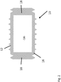
Fig. 1 is a cross-section of a cutting tool having a hollow hob according to an embodiment of the present disclosure. -
Fig. 2 is an enlarged cross-section of the hollow hob ofFig. 1 . -
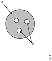
Fig. 3 is a cross-section of another embodiment of a hollow hob. -
Fig. 4 is a cross-section taken along line II-II ofFig. 3 . -
Figs. 5(a) - 5(c) are cross-sections of other embodiments of a hollow hob according to the present disclosure. -
Fig. 6 is yet another embodiment of a hollow hob according to the present disclosure. -
Fig. 7 is still another embodiment of a hollow hob according to the present disclosure. -
Fig. 8 is another embodiment of a hollow hob according to the present disclosure. -
Fig. 9 is a flow diagram illustrating a method of forming a hollow hob according to the present disclosure. - Referring to
Figs. 1 and2 , ahob 10 according to a present embodiment has abody 12 of a sintered hard metal composition of material. A hard metal composition is a composite material normally having a hard phase composed of one or more carbides, nitrides or carbonitrides of tungsten, titanium, chromium, vanadium, tantalum, niobium (or similar) bonded by a metallic phase, typically cobalt, nickel, iron (or combinations) or similar in varying proportions. Body 12 can be solid cemented carbide. Solid cemented carbide describes specified hard particulates combined with a specified binder alloy. For example, tungsten carbide bonded or cemented together by a cobalt alloy binder. - However, similarly to the above, solid cemented carbide may be tungsten, silicon, niobium, titanium, vanadium, chromium, tantalum, nickel, cobalt, or combinations thereof. The binder may often be cobalt or nickel. It should be appreciated that other materials for the members are contemplated by the present embodiments and therefore such should not be limited by a specific material.
-
Body 12 is a solid body of such material and is usually made by powder metallurgical methods, namely, but not limited to, for example, by pressing and sintering. The term solid body is defined as one contiguous, unitary body of material. However, the solid body is not limited to a specific homogenous composition, but may have a gradient, wherein relevant abundance of constituents vary across the body. It should also be appreciated that the composition of material is not limited to specific gradients. -
Body 12 has at least onecavity 14.Cavity 14 has a volume in the range of about 10% to about 90% of the volume of the body. Hence, the hollowsolid carbide hob 10 of the present embodiments would be lower in weight and therefore easier to handle, possible for machines to support and possible to achieve A or AA quality tolerances, according to DIN 3968 and/or BS ISO 4468, in solid carbide hobs in larger sizes than previously practical. - As shown in
Figs. 3 and4 ,body 12 can have a plurality of cavities 14', the specific number and position of the cavities inbody 12 being dependent on the particular end use of the hob. Moreover, the particular shape of the cavities can vary and although not shown, numerous different shapes of cavities are contemplated by the present disclosure. The total volume of the cavities can be of about 10% to about 90% of the volume of the solid body.Body 12 could be formed, for example, by extrusion, to have multiple cavities extending partially or through its entire length.Body 12 of the hob includes acore 16 having opposed ends. Anend plate 18 can be attached at each end of the core to form cavity 14 (14'). Each of the plates can be produced separately, for example, by direct pressing. As will be described further herein, after sintering the parts,core 16 andend plates 18 can be assembled and fused together, leaving the internal space orcavity 14.End plates 18 can be cemented carbide of the same composition ascore 16, or two or more different compositions and being different with respect to composition and/or grain size that are fused together, this would allow increased use of recycled material as compared to the core. - The hob of the present invention can have a plurality of different sintered parts fused to
core 16 orend plates 18, depending upon the desired end use of the hob. Referring toFigs. 5(a) - 5(c) ,core 16 can haveshank ends 20 attachable directly to the ends of core 16 (Fig. 5(a) ). Alternatively, ashank end 20 can be fused to an end plate and then to the core (Fig. 5(b) . For example,body 12 can have a Capto® coupling (Sandvik Coromant, Gimo, SE) attached thereto as shown inFig. 5(c) . It should be appreciated that a variety of parts can be fused or attached to the hob. For example, mantles, arbors, shanks, couplings, shafts and/or any other component or element. As discussed above, the elements fused to the core can be the same or different cemented carbide than the body or any other suitable material. - As shown in
Fig. 6 ,body 12 can be formed as a partially enclosedhob component 24 having acavity 26. One end ofcomponent 24 is enclosed the other end is open and sealable byend plate 18, or any other element. Cavity as used herein refers to an enclosed cavity, as well as, a recess formed in the body. - Referring to
Fig. 7 ,cavity 14 can be filled with avibration damping medium 28.Medium 28 can be introduced tocavity 14 through achannel 30 provided in theend plate 18 that is then subsequently sealed, e.g. with asteel plug 32. It should be appreciated that the cross-section of the channel leading to the cavity is less than the cross-section of the cavity. - Referring to
Fig. 8 , and as described supra, asintered part 34, such as an arbor or shank, can be fused tobody 12.Body 12 can include coolant holes 36 therein. Coolant may be introduced into acavity 14 throughchannel 30 provided in the shank plate and exit viaholes 34 to direct lubrication/cooling/flushing fluid directly to the cutting edge rather than flood cooling as is common today. - Referring to
Fig. 9 , amethod 50 of forming a hollow hob of a cutting tool according to the present embodiments is described. In step 52 abody 12 of the hob is provided.Body 12 has been sintered for obtaining substantially the full density and hardness thereof. As described above,body 12 can be a core 16 orcomponent 24 having the desired shape. - In
step 54 at least onecavity 14 is formed inbody 12 by fusing at least one sintered part such as an end plate/shanks 18 and or any other part tocore 16 /component 24 to enclose the cavity(ies) 14, 14', As described above,cavity 14 has a volume of about 10% to about 90% of the volume of the body.Plates 18 can be machined with channel(s) 28 or other features prior to sintering. - After the sintered members are assembled to form the desired shape of the hob and cavity heating occurs. Heating the members in the assembled relationship is employed to fuse the members together in such a way that one solid unitary
hollow hob body 12 is formed. No filler material or attachment material, such as brazing, is needed to attach the end plates or other parts to the core/component to form the body and cavity. - During fusing the assembled materials are subject to a vacuum or gas atmosphere, without the application of external pressure, and to a temperature sufficient to fuse the at plurality of materials together to form the unitary body. For example, at a temperature of about 1340°C to about 1360°C.
- Although the present embodiment(s) has been described in relation to particular aspects thereof, many other variations and modifications and other uses will become apparent to those skilled in the art. It is preferred therefore, that the present embodiment(s) be limited not by the specific disclosure herein, but only by the appended claims.
Claims (13)
- A hollow hob for a cutting apparatus comprising a body (12) of a sintered hard metal composition and at least one cavity (14) located within the body (12), wherein the cavity (14) has a volume in the range of about 10 % to about 90% of the volume of the body (12);
characterized in that:
the body (12) includes a core (16) having opposite sides and a sintered element fused to each side of the core (16) so as to seal the cavity (14) and form a unitary body. - The hollow hob according to claim 1, characterized in that the hard metal composition is solid cemented carbide.
- The hollow hob according to claims 1 or 2, characterized in that the hard metal composition comprises tungsten carbide.
- The hollow hob according to any of the preceding claims, characterized in that the hard metal composition comprises tungsten carbide bonded with a cobalt alloy binder.
- The hollow hob according to any of the preceding claims, characterized in that the hard metal comprises a composition selected from the group of tungsten, silicon, chromium, vanadium, tantalum, niobium, titanium, nickel, cobalt, iron and combinations thereof.
- The hollow hob according to claim 5, characterized in that the core (16) and each sintered element are cemented carbide of the same composition or of one or more different compositions.
- The hollow hob according to any of the preceding claims, characterized in that at least one sintered part is fused to the body (12).
- The hollow hob according to claim 7, wherein the at least one sintered part is a cemented carbide.
- The hollow hob according to any of the preceding claims, characterized in that a vibration dampening medium is disposed with the at least one cavity (14).
- The hollow hob according to any of the preceding claims, characterized in that a plurality of cavities are formed in the body (12).
- The hollow hob according to any of the preceding claims, characterized in that a plurality of coolant holes are disposed in the body (12).
- A method of forming a hollow hob of a cutting apparatus according to of the preceding claims comprising the steps of providing a hollow body (12) of a sintered hard metal composition, wherein at least one cavity (14) is located within the body (12), wherein the at least one cavity (14) has a volume in the range of about 10% to about 90% of the volume of the body (12), and wherein hollow body includes a core (16) having opposed sides; and
the method characterized by:
fusing a sintered element to each side of the core (16) so as to seal the at least one cavity (14) wherein each sintered element is fused to the body (12), wherein the hollow hob of the cutting apparatus is formed as a unitary body. - The method according to claim 12, characterized in that the hard metal composition is solid cemented carbide.
Applications Claiming Priority (2)
| Application Number | Priority Date | Filing Date | Title |
|---|---|---|---|
| US201361889105P | 2013-10-10 | 2013-10-10 | |
| PCT/IB2014/059795 WO2015052593A1 (en) | 2013-10-10 | 2014-03-14 | Hollow gear hob |
Publications (2)
| Publication Number | Publication Date |
|---|---|
| EP3055094A1 EP3055094A1 (en) | 2016-08-17 |
| EP3055094B1 true EP3055094B1 (en) | 2021-10-13 |
Family
ID=50473720
Family Applications (1)
| Application Number | Title | Priority Date | Filing Date |
|---|---|---|---|
| EP14716418.0A Active EP3055094B1 (en) | 2013-10-10 | 2014-03-14 | Hollow gear hob and a method of forming said hollow gear hob |
Country Status (4)
| Country | Link |
|---|---|
| US (2) | US10518345B2 (en) |
| EP (1) | EP3055094B1 (en) |
| ES (1) | ES2899893T3 (en) |
| WO (1) | WO2015052593A1 (en) |
Families Citing this family (1)
| Publication number | Priority date | Publication date | Assignee | Title |
|---|---|---|---|---|
| WO2015052593A1 (en) * | 2013-10-10 | 2015-04-16 | Sandvik Intellectual Property Ab | Hollow gear hob |
Family Cites Families (17)
| Publication number | Priority date | Publication date | Assignee | Title |
|---|---|---|---|---|
| US3715787A (en) * | 1970-11-25 | 1973-02-13 | A Hudson | Kinetic energy device for forming work pieces |
| US3786719A (en) * | 1972-05-04 | 1974-01-22 | K Kimura | Hobbing cutter |
| DE3601385A1 (en) | 1986-01-18 | 1987-07-23 | Krupp Gmbh | METHOD FOR PRODUCING SINTER BODIES WITH INNER CHANNELS, EXTRACTION TOOL FOR IMPLEMENTING THE METHOD, AND DRILLING TOOL |
| DE4445911C1 (en) * | 1994-12-22 | 1995-12-21 | Fette Wilhelm Gmbh | Coolant feeder for milling cutter |
| US6634835B1 (en) * | 2001-06-20 | 2003-10-21 | Torque-Traction Technologies Inc. | Cutter blade with integral coolant passages |
| DE10131333A1 (en) * | 2001-06-28 | 2003-05-15 | Fette Wilhelm Gmbh | hobs |
| DE10135282B4 (en) * | 2001-07-19 | 2004-01-15 | Wilhelm Fette Gmbh | hobs |
| US6630101B2 (en) * | 2001-08-16 | 2003-10-07 | Keystone Investment Corporation | Method for producing powder metal gears |
| DE10246871A1 (en) * | 2002-10-08 | 2004-05-06 | Sandvik Ab | Threading tool with coolant supply |
| SE527679C2 (en) * | 2004-01-26 | 2006-05-09 | Sandvik Intellectual Property | Carbide body, especially spiral drill, and its use for rotary metalworking tools |
| US20080298913A1 (en) * | 2007-06-04 | 2008-12-04 | The Boeing Company | Increased Process Damping Via Mass Reduction for High Performance Milling |
| JP5230391B2 (en) * | 2008-12-15 | 2013-07-10 | 三菱重工業株式会社 | Manufacturing method of carbide tools |
| DE102009016257B4 (en) * | 2008-12-16 | 2017-09-07 | Kennametal Inc. | hobs |
| DE102009029715A1 (en) | 2009-06-16 | 2010-12-23 | Komet Group Gmbh | Tool for machining workpieces |
| US8784016B2 (en) * | 2011-07-01 | 2014-07-22 | Kennametal Inc. | Rotary cutting tool with vibration damping device |
| DE102012001732B4 (en) * | 2012-01-31 | 2022-11-10 | Kennametal Inc. | Tool head for a modular shank tool, shank tool with such a tool head and manufacturing method for a tool head |
| WO2015052593A1 (en) * | 2013-10-10 | 2015-04-16 | Sandvik Intellectual Property Ab | Hollow gear hob |
-
2014
- 2014-03-14 WO PCT/IB2014/059795 patent/WO2015052593A1/en active Application Filing
- 2014-03-14 ES ES14716418T patent/ES2899893T3/en active Active
- 2014-03-14 EP EP14716418.0A patent/EP3055094B1/en active Active
- 2014-03-14 US US14/914,777 patent/US10518345B2/en active Active
-
2019
- 2019-09-16 US US16/572,178 patent/US11426811B2/en active Active
Non-Patent Citations (1)
| Title |
|---|
| None * |
Also Published As
| Publication number | Publication date |
|---|---|
| WO2015052593A1 (en) | 2015-04-16 |
| US20160207128A1 (en) | 2016-07-21 |
| US11426811B2 (en) | 2022-08-30 |
| ES2899893T3 (en) | 2022-03-15 |
| US20200038979A1 (en) | 2020-02-06 |
| US10518345B2 (en) | 2019-12-31 |
| EP3055094A1 (en) | 2016-08-17 |
Similar Documents
| Publication | Publication Date | Title |
|---|---|---|
| CN106141180B (en) | Cutting tool prepared by additive manufacturing | |
| US9498824B2 (en) | Method of joining sintered parts of different sizes and shapes | |
| US5447549A (en) | Hard alloy | |
| EP1960630B1 (en) | Methods of forming earth-boring rotary drill bits | |
| US8007922B2 (en) | Articles having improved resistance to thermal cracking | |
| US10399131B2 (en) | Compound roll | |
| US11426811B2 (en) | Hollow gear hob | |
| WO2014018235A2 (en) | Composite sintered powder metal articles | |
| JP7527754B2 (en) | Brazing Method | |
| WO2017011415A1 (en) | Infiltrated cutting tools and related methods | |
| JPS61182732A (en) | Method of forming cooling channel to metallic article | |
| EP2606996A1 (en) | A method for sintering metal matrix composite materials | |
| US20060239850A1 (en) | Endmills and method of making the same | |
| US9421611B2 (en) | Composite cutting insert and method of making same | |
| JP2018111108A (en) | Composite member and cutting tool comprising the composite member |
Legal Events
| Date | Code | Title | Description |
|---|---|---|---|
| PUAI | Public reference made under article 153(3) epc to a published international application that has entered the european phase |
Free format text: ORIGINAL CODE: 0009012 |
|
| 17P | Request for examination filed |
Effective date: 20160510 |
|
| AK | Designated contracting states |
Kind code of ref document: A1 Designated state(s): AL AT BE BG CH CY CZ DE DK EE ES FI FR GB GR HR HU IE IS IT LI LT LU LV MC MK MT NL NO PL PT RO RS SE SI SK SM TR |
|
| AX | Request for extension of the european patent |
Extension state: BA ME |
|
| DAX | Request for extension of the european patent (deleted) | ||
| RAP1 | Party data changed (applicant data changed or rights of an application transferred) |
Owner name: SANDVIK HYPERION AB |
|
| RAP1 | Party data changed (applicant data changed or rights of an application transferred) |
Owner name: HYPERION MATERIALS & TECHNOLOGIES (SWEDEN) AB |
|
| STAA | Information on the status of an ep patent application or granted ep patent |
Free format text: STATUS: EXAMINATION IS IN PROGRESS |
|
| 17Q | First examination report despatched |
Effective date: 20190503 |
|
| STAA | Information on the status of an ep patent application or granted ep patent |
Free format text: STATUS: EXAMINATION IS IN PROGRESS |
|
| GRAP | Despatch of communication of intention to grant a patent |
Free format text: ORIGINAL CODE: EPIDOSNIGR1 |
|
| STAA | Information on the status of an ep patent application or granted ep patent |
Free format text: STATUS: GRANT OF PATENT IS INTENDED |
|
| INTG | Intention to grant announced |
Effective date: 20210702 |
|
| GRAS | Grant fee paid |
Free format text: ORIGINAL CODE: EPIDOSNIGR3 |
|
| GRAA | (expected) grant |
Free format text: ORIGINAL CODE: 0009210 |
|
| STAA | Information on the status of an ep patent application or granted ep patent |
Free format text: STATUS: THE PATENT HAS BEEN GRANTED |
|
| AK | Designated contracting states |
Kind code of ref document: B1 Designated state(s): AL AT BE BG CH CY CZ DE DK EE ES FI FR GB GR HR HU IE IS IT LI LT LU LV MC MK MT NL NO PL PT RO RS SE SI SK SM TR |
|
| REG | Reference to a national code |
Ref country code: GB Ref legal event code: FG4D |
|
| REG | Reference to a national code |
Ref country code: CH Ref legal event code: EP |
|
| REG | Reference to a national code |
Ref country code: DE Ref legal event code: R096 Ref document number: 602014080633 Country of ref document: DE |
|
| REG | Reference to a national code |
Ref country code: IE Ref legal event code: FG4D |
|
| REG | Reference to a national code |
Ref country code: AT Ref legal event code: REF Ref document number: 1437818 Country of ref document: AT Kind code of ref document: T Effective date: 20211115 |
|
| REG | Reference to a national code |
Ref country code: LT Ref legal event code: MG9D |
|
| REG | Reference to a national code |
Ref country code: NL Ref legal event code: MP Effective date: 20211013 |
|
| REG | Reference to a national code |
Ref country code: ES Ref legal event code: FG2A Ref document number: 2899893 Country of ref document: ES Kind code of ref document: T3 Effective date: 20220315 Ref country code: AT Ref legal event code: MK05 Ref document number: 1437818 Country of ref document: AT Kind code of ref document: T Effective date: 20211013 |
|
| PG25 | Lapsed in a contracting state [announced via postgrant information from national office to epo] |
Ref country code: RS Free format text: LAPSE BECAUSE OF FAILURE TO SUBMIT A TRANSLATION OF THE DESCRIPTION OR TO PAY THE FEE WITHIN THE PRESCRIBED TIME-LIMIT Effective date: 20211013 Ref country code: LT Free format text: LAPSE BECAUSE OF FAILURE TO SUBMIT A TRANSLATION OF THE DESCRIPTION OR TO PAY THE FEE WITHIN THE PRESCRIBED TIME-LIMIT Effective date: 20211013 Ref country code: FI Free format text: LAPSE BECAUSE OF FAILURE TO SUBMIT A TRANSLATION OF THE DESCRIPTION OR TO PAY THE FEE WITHIN THE PRESCRIBED TIME-LIMIT Effective date: 20211013 Ref country code: BG Free format text: LAPSE BECAUSE OF FAILURE TO SUBMIT A TRANSLATION OF THE DESCRIPTION OR TO PAY THE FEE WITHIN THE PRESCRIBED TIME-LIMIT Effective date: 20220113 Ref country code: AT Free format text: LAPSE BECAUSE OF FAILURE TO SUBMIT A TRANSLATION OF THE DESCRIPTION OR TO PAY THE FEE WITHIN THE PRESCRIBED TIME-LIMIT Effective date: 20211013 |
|
| PG25 | Lapsed in a contracting state [announced via postgrant information from national office to epo] |
Ref country code: IS Free format text: LAPSE BECAUSE OF FAILURE TO SUBMIT A TRANSLATION OF THE DESCRIPTION OR TO PAY THE FEE WITHIN THE PRESCRIBED TIME-LIMIT Effective date: 20220213 Ref country code: SE Free format text: LAPSE BECAUSE OF FAILURE TO SUBMIT A TRANSLATION OF THE DESCRIPTION OR TO PAY THE FEE WITHIN THE PRESCRIBED TIME-LIMIT Effective date: 20211013 Ref country code: PT Free format text: LAPSE BECAUSE OF FAILURE TO SUBMIT A TRANSLATION OF THE DESCRIPTION OR TO PAY THE FEE WITHIN THE PRESCRIBED TIME-LIMIT Effective date: 20220214 Ref country code: PL Free format text: LAPSE BECAUSE OF FAILURE TO SUBMIT A TRANSLATION OF THE DESCRIPTION OR TO PAY THE FEE WITHIN THE PRESCRIBED TIME-LIMIT Effective date: 20211013 Ref country code: NO Free format text: LAPSE BECAUSE OF FAILURE TO SUBMIT A TRANSLATION OF THE DESCRIPTION OR TO PAY THE FEE WITHIN THE PRESCRIBED TIME-LIMIT Effective date: 20220113 Ref country code: NL Free format text: LAPSE BECAUSE OF FAILURE TO SUBMIT A TRANSLATION OF THE DESCRIPTION OR TO PAY THE FEE WITHIN THE PRESCRIBED TIME-LIMIT Effective date: 20211013 Ref country code: LV Free format text: LAPSE BECAUSE OF FAILURE TO SUBMIT A TRANSLATION OF THE DESCRIPTION OR TO PAY THE FEE WITHIN THE PRESCRIBED TIME-LIMIT Effective date: 20211013 Ref country code: HR Free format text: LAPSE BECAUSE OF FAILURE TO SUBMIT A TRANSLATION OF THE DESCRIPTION OR TO PAY THE FEE WITHIN THE PRESCRIBED TIME-LIMIT Effective date: 20211013 Ref country code: GR Free format text: LAPSE BECAUSE OF FAILURE TO SUBMIT A TRANSLATION OF THE DESCRIPTION OR TO PAY THE FEE WITHIN THE PRESCRIBED TIME-LIMIT Effective date: 20220114 |
|
| REG | Reference to a national code |
Ref country code: DE Ref legal event code: R097 Ref document number: 602014080633 Country of ref document: DE |
|
| PG25 | Lapsed in a contracting state [announced via postgrant information from national office to epo] |
Ref country code: SM Free format text: LAPSE BECAUSE OF FAILURE TO SUBMIT A TRANSLATION OF THE DESCRIPTION OR TO PAY THE FEE WITHIN THE PRESCRIBED TIME-LIMIT Effective date: 20211013 Ref country code: SK Free format text: LAPSE BECAUSE OF FAILURE TO SUBMIT A TRANSLATION OF THE DESCRIPTION OR TO PAY THE FEE WITHIN THE PRESCRIBED TIME-LIMIT Effective date: 20211013 Ref country code: RO Free format text: LAPSE BECAUSE OF FAILURE TO SUBMIT A TRANSLATION OF THE DESCRIPTION OR TO PAY THE FEE WITHIN THE PRESCRIBED TIME-LIMIT Effective date: 20211013 Ref country code: EE Free format text: LAPSE BECAUSE OF FAILURE TO SUBMIT A TRANSLATION OF THE DESCRIPTION OR TO PAY THE FEE WITHIN THE PRESCRIBED TIME-LIMIT Effective date: 20211013 Ref country code: DK Free format text: LAPSE BECAUSE OF FAILURE TO SUBMIT A TRANSLATION OF THE DESCRIPTION OR TO PAY THE FEE WITHIN THE PRESCRIBED TIME-LIMIT Effective date: 20211013 Ref country code: CZ Free format text: LAPSE BECAUSE OF FAILURE TO SUBMIT A TRANSLATION OF THE DESCRIPTION OR TO PAY THE FEE WITHIN THE PRESCRIBED TIME-LIMIT Effective date: 20211013 |
|
| PLBE | No opposition filed within time limit |
Free format text: ORIGINAL CODE: 0009261 |
|
| STAA | Information on the status of an ep patent application or granted ep patent |
Free format text: STATUS: NO OPPOSITION FILED WITHIN TIME LIMIT |
|
| 26N | No opposition filed |
Effective date: 20220714 |
|
| PG25 | Lapsed in a contracting state [announced via postgrant information from national office to epo] |
Ref country code: MC Free format text: LAPSE BECAUSE OF FAILURE TO SUBMIT A TRANSLATION OF THE DESCRIPTION OR TO PAY THE FEE WITHIN THE PRESCRIBED TIME-LIMIT Effective date: 20211013 Ref country code: AL Free format text: LAPSE BECAUSE OF FAILURE TO SUBMIT A TRANSLATION OF THE DESCRIPTION OR TO PAY THE FEE WITHIN THE PRESCRIBED TIME-LIMIT Effective date: 20211013 |
|
| PG25 | Lapsed in a contracting state [announced via postgrant information from national office to epo] |
Ref country code: SI Free format text: LAPSE BECAUSE OF FAILURE TO SUBMIT A TRANSLATION OF THE DESCRIPTION OR TO PAY THE FEE WITHIN THE PRESCRIBED TIME-LIMIT Effective date: 20211013 |
|
| PG25 | Lapsed in a contracting state [announced via postgrant information from national office to epo] |
Ref country code: LU Free format text: LAPSE BECAUSE OF NON-PAYMENT OF DUE FEES Effective date: 20220314 Ref country code: IE Free format text: LAPSE BECAUSE OF NON-PAYMENT OF DUE FEES Effective date: 20220314 |
|
| P01 | Opt-out of the competence of the unified patent court (upc) registered |
Effective date: 20230703 |
|
| PG25 | Lapsed in a contracting state [announced via postgrant information from national office to epo] |
Ref country code: HU Free format text: LAPSE BECAUSE OF FAILURE TO SUBMIT A TRANSLATION OF THE DESCRIPTION OR TO PAY THE FEE WITHIN THE PRESCRIBED TIME-LIMIT; INVALID AB INITIO Effective date: 20140314 |
|
| PG25 | Lapsed in a contracting state [announced via postgrant information from national office to epo] |
Ref country code: MK Free format text: LAPSE BECAUSE OF FAILURE TO SUBMIT A TRANSLATION OF THE DESCRIPTION OR TO PAY THE FEE WITHIN THE PRESCRIBED TIME-LIMIT Effective date: 20211013 Ref country code: CY Free format text: LAPSE BECAUSE OF FAILURE TO SUBMIT A TRANSLATION OF THE DESCRIPTION OR TO PAY THE FEE WITHIN THE PRESCRIBED TIME-LIMIT Effective date: 20211013 |
|
| PGFP | Annual fee paid to national office [announced via postgrant information from national office to epo] |
Ref country code: DE Payment date: 20240327 Year of fee payment: 11 Ref country code: GB Payment date: 20240327 Year of fee payment: 11 |
|
| PGFP | Annual fee paid to national office [announced via postgrant information from national office to epo] |
Ref country code: IT Payment date: 20240321 Year of fee payment: 11 Ref country code: FR Payment date: 20240325 Year of fee payment: 11 Ref country code: BE Payment date: 20240327 Year of fee payment: 11 |
|
| PGFP | Annual fee paid to national office [announced via postgrant information from national office to epo] |
Ref country code: CH Payment date: 20240402 Year of fee payment: 11 |
|
| PGFP | Annual fee paid to national office [announced via postgrant information from national office to epo] |
Ref country code: ES Payment date: 20240401 Year of fee payment: 11 |