EP3054534A1 - Electronic control device - Google Patents
Electronic control device Download PDFInfo
- Publication number
- EP3054534A1 EP3054534A1 EP14851353.4A EP14851353A EP3054534A1 EP 3054534 A1 EP3054534 A1 EP 3054534A1 EP 14851353 A EP14851353 A EP 14851353A EP 3054534 A1 EP3054534 A1 EP 3054534A1
- Authority
- EP
- European Patent Office
- Prior art keywords
- control device
- electronic control
- opening part
- resin base
- substrate
- Prior art date
- Legal status (The legal status is an assumption and is not a legal conclusion. Google has not performed a legal analysis and makes no representation as to the accuracy of the status listed.)
- Granted
Links
Images




Classifications
-
- H—ELECTRICITY
- H05—ELECTRIC TECHNIQUES NOT OTHERWISE PROVIDED FOR
- H05K—PRINTED CIRCUITS; CASINGS OR CONSTRUCTIONAL DETAILS OF ELECTRIC APPARATUS; MANUFACTURE OF ASSEMBLAGES OF ELECTRICAL COMPONENTS
- H05K7/00—Constructional details common to different types of electric apparatus
- H05K7/20—Modifications to facilitate cooling, ventilating, or heating
- H05K7/20845—Modifications to facilitate cooling, ventilating, or heating for automotive electronic casings
- H05K7/20854—Heat transfer by conduction from internal heat source to heat radiating structure
-
- H—ELECTRICITY
- H01—ELECTRIC ELEMENTS
- H01R—ELECTRICALLY-CONDUCTIVE CONNECTIONS; STRUCTURAL ASSOCIATIONS OF A PLURALITY OF MUTUALLY-INSULATED ELECTRICAL CONNECTING ELEMENTS; COUPLING DEVICES; CURRENT COLLECTORS
- H01R12/00—Structural associations of a plurality of mutually-insulated electrical connecting elements, specially adapted for printed circuits, e.g. printed circuit boards [PCB], flat or ribbon cables, or like generally planar structures, e.g. terminal strips, terminal blocks; Coupling devices specially adapted for printed circuits, flat or ribbon cables, or like generally planar structures; Terminals specially adapted for contact with, or insertion into, printed circuits, flat or ribbon cables, or like generally planar structures
- H01R12/70—Coupling devices
- H01R12/71—Coupling devices for rigid printing circuits or like structures
- H01R12/72—Coupling devices for rigid printing circuits or like structures coupling with the edge of the rigid printed circuits or like structures
- H01R12/721—Coupling devices for rigid printing circuits or like structures coupling with the edge of the rigid printed circuits or like structures cooperating directly with the edge of the rigid printed circuits
-
- H—ELECTRICITY
- H05—ELECTRIC TECHNIQUES NOT OTHERWISE PROVIDED FOR
- H05K—PRINTED CIRCUITS; CASINGS OR CONSTRUCTIONAL DETAILS OF ELECTRIC APPARATUS; MANUFACTURE OF ASSEMBLAGES OF ELECTRICAL COMPONENTS
- H05K1/00—Printed circuits
- H05K1/02—Details
- H05K1/0201—Thermal arrangements, e.g. for cooling, heating or preventing overheating
- H05K1/0203—Cooling of mounted components
-
- H—ELECTRICITY
- H05—ELECTRIC TECHNIQUES NOT OTHERWISE PROVIDED FOR
- H05K—PRINTED CIRCUITS; CASINGS OR CONSTRUCTIONAL DETAILS OF ELECTRIC APPARATUS; MANUFACTURE OF ASSEMBLAGES OF ELECTRICAL COMPONENTS
- H05K5/00—Casings, cabinets or drawers for electric apparatus
- H05K5/0026—Casings, cabinets or drawers for electric apparatus provided with connectors and printed circuit boards [PCB], e.g. automotive electronic control units
- H05K5/0039—Casings, cabinets or drawers for electric apparatus provided with connectors and printed circuit boards [PCB], e.g. automotive electronic control units having a tubular housing wherein the PCB is inserted longitudinally
-
- H—ELECTRICITY
- H01—ELECTRIC ELEMENTS
- H01R—ELECTRICALLY-CONDUCTIVE CONNECTIONS; STRUCTURAL ASSOCIATIONS OF A PLURALITY OF MUTUALLY-INSULATED ELECTRICAL CONNECTING ELEMENTS; COUPLING DEVICES; CURRENT COLLECTORS
- H01R13/00—Details of coupling devices of the kinds covered by groups H01R12/70 or H01R24/00 - H01R33/00
- H01R13/46—Bases; Cases
- H01R13/52—Dustproof, splashproof, drip-proof, waterproof, or flameproof cases
- H01R13/5219—Sealing means between coupling parts, e.g. interfacial seal
Definitions
- the present invention relates to a control device on which an electronic component is mounted, in particular, to an electronic control device having a circuit substrate on which an electronic component is mounted.
- An electronic control device which can improve reliability of connection between a connector terminal and a land corresponding to the connector terminal and reduce a manufacturing cost thereof is known (for example, see PTL 1).
- the electronic control device is provided with a substrate on which an electronic component is mounted, the substrate having a land on the surface, a surface mounting-type connector which has a plurality of terminals, each of which electrically connects an external connector and the substrate, disposed in a housing and electrically connected to corresponding lands, and a casing having a connector opening part to connect the connector and the external connector and storing the substrate and the connector.
- the housing is provided with a holding part for holding the plurality of terminals, and a protection part having a fixation portion for fixing the holding part, the protection part protecting a portion of the terminal exposed from the holding part and connected to the external connector.
- the casing has a fitting part, which is fitted to a housing of the external connector, for electrically connecting the connector and the external connector.
- the conventional electronic control device leads to an increase in a number of components for ensuring a waterproof property.
- An object of the present invention is to provide an electronic control device capable of ensuring a waterproof property while suppressing a number of components.
- the present invention is an electronic control device including: a resin base having at least one opening part; a first resin cover fixed on an inner surface of the resin base forming a first opening part and formed in a cylindrical shape having a bottom and a first slit; a substrate having a first connector inserted into the first slit; and an electronic component mounted on the substrate.
- the electronic control device is, for example, formed to control a device (fuel injection device, automatic transmission mechanism, or the like) mounted on a vehicle.
- a device fuel injection device, automatic transmission mechanism, or the like mounted on a vehicle.
- the same reference numerals are assigned to the same parts.
- FIG. 1A is a cross-sectional view of the electronic control device 100A according to a first embodiment of the present invention.
- the electronic control device 100A is provided with a resin base 11 (housing), a substrate 12, and a resin cover 13.
- the resin base 11 formed in a cylindrical shape with a bottom has an opening part OP1.
- An electronic component 14 is mounted on the substrate 12.
- the substrate 12 has a card edge connector 12a electrically connected to an external female connector.
- the card edge connector 12a is inserted into a slit 13a formed on the resin cover 13.
- the resin cover 13 is fixed on an inner surface of the resin base 11 forming the opening part OP1.
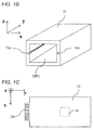
- FIG. 1B is a perspective view of the resin base 11 used in the electronic control device 100A according to the first embodiment of the present invention.
- the resin base 11 is provided with a guide 11a (groove) on the inner surface forming the opening part OP1.
- the substrate 12 is slid along the guide 11a and inserted.
- FIG. 1C is a top view of the substrate 12 used in the electronic control device 100A according to the first embodiment of the present invention.
- the substrate 12 has the card edge connector 12a protruding in a longitudinal direction (y-axis (-)) of the substrate 12.
- the card edge connector 12a is electrically connected to the electronic component 14 via wiring mounted on the substrate 12.
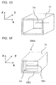
- FIG. 1D is a perspective view of the resin cover 13 used in the electronic control device 100A according to the first embodiment of the present invention.
- the resin cover 13 formed in a cylindrical shape with a bottom has the slit 13a at a bottom part thereof.
- the card edge connector 12a shown in FIG. 1C is inserted into the slit 13.
- FIG. 1E is a perspective view of the electronic control device 100A according to the first embodiment of the present invention.
- the resin cover 13 is disposed to cover the opening part OP of the resin base 11 and fixed by an adhesive or the like.
- the card edge connector 12a mounted on the substrate 12 is inserted into the slit 13a formed on the resin cover 13.
- the card edge connector 12a is protruded from the slit 13a.
- the resin base 11 forming the opening part OP1, the resin cover 13 and the card edge connector 12a are served as a male connector. That is, the opening part OP1 is served as a connector frontage.
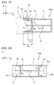
- FIG. 1F illustrates a connection of the electronic control device 100A and an external female connector 17 according to the first embodiment of the present invention.
- an edge part of the electronic control device 100A at a side in which the card edge connector 12a is protruded is fitted with the external female connector 17.
- a stepped part is formed by an edge 13b of the resin cover 13 and the inner surface of the resin base 11 forming the opening part.
- a sealing member 15 (for example, an elastic member such as a rubber seal) provided on the external female connector 17 is contacted with the stepped part.
- a distance D1 between the bottom part of the resin cover 13 and the edge 13b of the resin cover 13 is shorter than a distance D2 between the bottom part of the resin cover 13 and an edge 11b of the resin base 11.
- the sealing member 15 waterproofs the card edge connector 12a. Further, the sealing member 15 prevents liquid such as water from entering the electronic control device 100A through a region where the slit 13a formed on the resin cover 13 and the substrate 12 are contacted with each other. Further, the sealing member 15 prevents water from entering the electronic control device 100A through a region where the resin cover 13 and the resin base 11 are contacted with each other.
- the present embodiment it makes possible to ensure a waterproof property while suppressing a number of components. Further, less number of the components facilitates its assembling. Accordingly, the manufacturing cost can be reduced.
- FIG. 2A is a cross-sectional view of the electronic control device 100B according to a second embodiment of the present invention.
- the electronic control device 100A is provided with a resin base 11, a substrate 12, and resin covers 13 (13 1 and 13 2 ).
- the resin base 11 has opening parts OP1 and OP2.
- the opening part OP1 and the opening part OP2 are communicated with each other. That is, the resin base 11 is formed in a cylindrical shape.
- the opening part OP1 and the opening part OP2 are arranged to face each other.
- the substrate 12 has card edge connectors 12a (12a 1 and 12a 2 ) electrically connected to an external female connector.
- the card edge connector 12a 1 is inserted into a slit 13a 1 formed on the resin cover 13 1 .
- the card edge connector 12a 2 is inserted in to a slit 13a 2 formed on the resin cover 13 2 .
- the resin cover 13 1 is fixed on an inner surface of the resin base 11 forming the opening part OP1.
- the resin cover 13 2 is fixed on an inner surface of the resin base 11 forming the opening part OP2.
- the resin cover 13 1 and the resin cover 13 2 are arranged to face each other.
- FIG. 2B illustrates a connection of the electronic control device 100B and an external female connector 17 according to the second embodiment of the present invention.
- an edge part of the electronic control device 100B at a side in which the card edge connector 12a 1 is protruded is fitted with the external female connector 17 1 .
- An edge part of the electronic control device 100B at a side in which the card edge connector 12a 2 is protruded is fitted with the external female connector 17 2 .
- a sealing member 15 1 waterproofs the card edge connector 12a 1 . Further, the sealing member 15 1 prevents liquid such as water from entering the electronic control device 100B through a region where the slit 13a 1 formed on the resin cover 13 1 and the substrate 12 are contacted with each other. Further, the sealing member 15 1 prevents liquid such as water from entering the electronic control device 100B through a region where the resin cover 13 1 and the resin base 11 are contacted with each other.
- a sealing member 15 2 waterproofs the card edge connector 12a 2 . Further, the sealing member 15 2 prevents liquid such as water from entering the electronic control device 100B through a region where the slit 13a 2 formed on the resin cover 13 2 and the substrate 12 are contacted with each other. Further, the sealing member 15 2 prevents liquid such as water from entering the electronic control device 100B through a region where the resin cover 13 2 and the resin base 11 are contacted with each other.
- the present embodiment it makes possible to ensure a waterproof property while suppressing a number of components. Further, less number of the components facilitates its assembling. Accordingly, the manufacturing cost can be reduced.
- FIG. 3 is a perspective view of the electronic control device 100C according to a third embodiment of the present invention.
- the electronic control device 100C is provided with a resin base 11, a substrate 12, and four resin covers 13 (13 1 , 13 2 , ).
- the resin base 11 has four opening parts OP (OP1, OP2, OP3, and OP4).
- all the opening parts OP are communicated with each other.
- the opening part OP1 and the opening part OP2 are arranged to face each other, and the opening part OP3 and the opening part OP4 are arranged to face each other.
- the opening part OP1 and the opening part OP3 are arranged to be perpendicular to each other.
- the substrate 12 (not shown) has four card edge connectors 12a formed in four directions, respectively, and each of the card edge connector is connected to an external connector.
- the four resin covers 13 (13 1 , 13 2 , 13 3 , and 13 4 ) are disposed and fixed to cover the four opening parts OP (OP1, OP2, OP3, and OP4), respectively.
- the opening parts OP (OP1, OP2, OP3, and OP4) are formed at edge surfaces of the resin base 11 perpendicular to the substrate 12 on which an electronic component 14 is mounted.
- Four external female connectors 17 (not shown) are fitted with four opening parts OP (OP1, OP2, OP3, and OP4) served as connector frontages, respectively, by moving in respective directions shown by arrows 16.
- the present embodiment it makes possible to ensure a waterproof property while suppressing a number of components. Further, less number of the components facilitates its assembling. Accordingly, the manufacturing cost can be reduced. Furthermore, a plurality of external female connectors 17 can be connected.
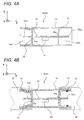
- FIG. 4A is a cross-sectional view of the electronic control device 100D according to a fourth embodiment of the present invention.
- the electronic control device 100D is provided with a resin base 11, a substrate 12, a resin cover 13, and a partition wall 31.
- a card edge connector 12a 2 is inserted into a slit 31a formed on the partition wall 31.
- the partition wall 31 is integrally formed with an inner surface of the resin base 11 forming an opening part OP2.
- FIG. 4B illustrates a connection of the electronic control device 100D and external female connectors 17 and 26 according to the fourth embodiment of the present invention.
- a sealing member 27 (for example, an elastic member such as a rubber seal) disposed on the external female connector 26 waterproofs the card edge connector 12a 2 . Further, the sealing member 27 prevents liquid from entering the electronic control device 100D through a region where the slit 31a formed on the partition wall 31 and the substrate 12 are contacted with each other.
- the present embodiment it makes possible to ensure a waterproof property while suppressing a number of components. Further, less number of the components facilitates its assembling. Accordingly, the manufacturing cost can be reduced.
- FIG. 5A is a cross-sectional view of the electronic control device 100E according to a fifth embodiment of the present invention.
- the electronic control device 100E is provided with a resin base 11, a substrate 12, a resin cover 13, and a partition wall 31.
- the resin cover 13 has a snap fit 18 at a bottom part thereof.
- the snap fit 18 is engaged with a projection 11c formed on an inner surface of the resin base 11. With such a configuration, the resin cover 13 is fixed on the inner surface of the resin base 11 forming an opening part OP1.
- the variation in dimensions of the substrate 12 can be absorbed by the snap fit 18.
- the snap fits 18 are provided at an upper part (z-axis (+) side) and a lower part (z-axis (-) side) of a bottom part of the resin cover 13.
- a hole H1 of the partition wall 31 is formed for a die forming the projection 11c.
- the present embodiment it makes possible to ensure a waterproof property while suppressing a number of components. Further, less number of the components facilitates its assembling. Accordingly, the manufacturing cost can be reduced. Furthermore, the variation in dimensions of the substrate 12 can be absorbed.
- FIG. 5B is a cross-sectional view of the variation of the electronic control device 100E according to the fifth embodiment of the present invention.
- FIG. 5B the position of the snap fit 18 is different from that in FIG. 5A . That is, in FIG. 5A , the snap fits 18 are provided at a left part (x-axis (+) side) and a right part (x-axis (-) side) of the bottom part of the resin cover 13.
- FIG. 6 is a cross-sectional view of the electronic control device 100F according to a sixth embodiment of the present invention.
- the electronic control device 100F is provided with a resin base 11, a substrate 12, a resin cover 13, a partition wall 31, and a heat radiation member 19.
- the heat radiation member 19 (for example, a metal member) has a projection 19a.
- the projection 19a is, for example, formed by drawing the center region of a metal plate.
- the resin base 11 has an opening part for the heat radiation member at a lower part (z-axis (-) side) of the resin base 11. The opening part is communicated with an electronic component 14.
- the projection 19a of the heat radiation member 19 is fitted with the opening part for the heat radiation member to be adjacent to the electronic component 14.
- the heat radiation member 19 and the electronic component 14 are fixed to each other by a heat radiating filler 20 1 (heat radiating adhesive). With such a configuration, heat generated by the electronic component 14 is transferred to the heat radiation member 19 via the filler 20 1 and radiated.
- the heat radiation member 19 and the resin base 11 are fixed to each other by a non-heat radiating filler 20 2 .
- a non-heat radiating filler 20 2 With such a configuration, an inner space of the electronic control device 100F is waterproofed.
- the heat radiating filler 20 1 may be used instead of the non-heat radiating filler 20 2 .
- the present embodiment it makes possible to ensure a waterproof property while suppressing a number of components. Further, less number of the components facilitates its assembling. Accordingly, the manufacturing cost can be reduced. Furthermore, it makes possible to radiate heat of the electronic component while suppressing a number of components.
- FIG. 7 is a front view of the variation of the electronic control device 100F according to the sixth embodiment of the present invention.
- a heat radiation member 19 has a hole H2 into which a screw 22 is inserted.
- the screw 22 is inserted into the hole H2 and screwed with a female screw (screw hole) disposed on a vehicle body.
- the screw 22 and the hole H2 are served as a fixing part which fixes the heat radiation member 19 on the vehicle body. With such a configuration, the electronic control device 100F is fixed on the vehicle body.
- the present embodiment it makes possible to ensure a waterproof property while suppressing a number of components. Further, less number of the components facilitates its assembling. Accordingly, the manufacturing cost can be reduced. Furthermore, it makes possible to radiate heat of the electronic component while suppressing a number of components.
- FIG. 8 is a front view of the electronic control device 100G according to a seventh embodiment of the present invention.
- the electronic control device 100G is provided with a resin base 11, a substrate 12, a resin cover 13, and a clip 23.
- the resin base 11 is held such that the resin base 11 is interposed by a pair of clips 23 fixed on a vehicle body. With such a configuration, fixation of the electronic control device 100F onto the vehicle body can be facilitated.
- the present embodiment it makes possible to ensure a waterproof property while suppressing a number of components. Further, less number of the components facilitates its assembling. Accordingly, the manufacturing cost can be reduced.
- the present invention is not limited to the embodiments described above and may include various types of variations.
- the embodiments described above are merely described for easy understanding of the present invention, and are not necessarily limited to what includes all of the described configurations. Further, a part of a configuration of a certain embodiment can be substituted by a configuration of another embodiment, and a configuration of another embodiment can be added to a configuration of a certain embodiment. Addition, deletion, or substitution of other configurations can be carried out for parts of configurations of the respective embodiments.
- FIG. 9A is a top view of the box-type connector 24 used in the electronic control device according to the first through seventh embodiments of the present invention.
- FIG. 9B is a side view of the box-type connector 24 shown in FIG. 9A .
Landscapes
- Engineering & Computer Science (AREA)
- Microelectronics & Electronic Packaging (AREA)
- Physics & Mathematics (AREA)
- Thermal Sciences (AREA)
- Casings For Electric Apparatus (AREA)
- Mounting Of Printed Circuit Boards And The Like (AREA)
- Connection Or Junction Boxes (AREA)
Abstract
Description
- The present invention relates to a control device on which an electronic component is mounted, in particular, to an electronic control device having a circuit substrate on which an electronic component is mounted.
- An electronic control device which can improve reliability of connection between a connector terminal and a land corresponding to the connector terminal and reduce a manufacturing cost thereof is known (for example, see PTL 1).
- In
PTL 1, it is described that the electronic control device is provided with a substrate on which an electronic component is mounted, the substrate having a land on the surface, a surface mounting-type connector which has a plurality of terminals, each of which electrically connects an external connector and the substrate, disposed in a housing and electrically connected to corresponding lands, and a casing having a connector opening part to connect the connector and the external connector and storing the substrate and the connector. The housing is provided with a holding part for holding the plurality of terminals, and a protection part having a fixation portion for fixing the holding part, the protection part protecting a portion of the terminal exposed from the holding part and connected to the external connector. And the casing has a fitting part, which is fitted to a housing of the external connector, for electrically connecting the connector and the external connector. - PTL 1:
JP 2007-335254 A - In the electronic control device disclosed in
PTL 1, in order to reduce stress in fitting the connector, it is necessary to fix the housing, which fixes the connector terminal, and the external connector by using a sealing material. Further, the casing is formed to interpose the substrate in a vertical direction, and therefore sealing an upper and a lower casings by the sealing material is necessary. Further, since it is impossible to fix the housing, which includes the terminal electrically connecting the external connector and the substrate, with respect to a planar direction of the substrate, fixing the housing by another component or the sealing material is necessary. - In this way, the conventional electronic control device leads to an increase in a number of components for ensuring a waterproof property.
- An object of the present invention is to provide an electronic control device capable of ensuring a waterproof property while suppressing a number of components.
- In order to achieve the object, the present invention is an electronic control device including: a resin base having at least one opening part; a first resin cover fixed on an inner surface of the resin base forming a first opening part and formed in a cylindrical shape having a bottom and a first slit; a substrate having a first connector inserted into the first slit; and an electronic component mounted on the substrate.
- According to the present invention, ensuring the waterproof property while suppressing the number of components can be achieved. Other objects, features, and advantages of the present invention will become apparent from the following description of embodiments.
-
- [
FIG. 1A] FIG. 1A is a cross-sectional view of an electronic control device according to a first embodiment of the present invention. - [
FIG. 1B] FIG. 1B is a perspective view of a resin base used in the electronic control device according to the first embodiment of the present invention. - [
FIG. 1C] FIG. 1C is a top view of a substrate used in the electronic control device according to the first embodiment of the present invention. - [
FIG. 1D] FIG. 1D is a perspective view of a resin cover used in the electronic control device according to the first embodiment of the present invention. - [
FIG. 1E] FIG. 1E is a perspective view of the electronic control device according to the first embodiment of the present invention. - [
FIG. 1F] FIG. 1F illustrates a connection of the electronic control device and an external female connector according to the first embodiment of the present invention. - [
FIG. 2A] FIG. 2A is a cross-sectional view of an electronic control device according to a second embodiment of the present invention. - [
FIG. 2B] FIG. 2B illustrates a connection of the electronic control device and an external female connector according to the second embodiment of the present invention. - [
FIG. 3] FIG. 3 is a perspective view of an electronic control device according to a third embodiment of the present invention. - [
FIG. 4A] FIG. 4A is a cross-sectional view of an electronic control device according to a fourth embodiment of the present invention. - [
FIG. 4B] FIG. 4B illustrates a connection of the electronic control device and an external female connector according to the fourth embodiment of the present invention. - [
FIG. 5A] FIG. 5A is a cross-sectional view of an electronic control device according to a fifth embodiment of the present invention. - [
FIG. 5B] FIG. 5B is a cross-sectional view of a variation of the electronic control device according to the fifth embodiment of the present invention. - [
FIG. 6] FIG. 6 is a cross-sectional view of an electronic control device according to a sixth embodiment of the present invention. - [
FIG. 7] FIG. 7 is a front view of a variation of the electronic control device according to the sixth embodiment of the present invention. - [
FIG. 8] FIG. 8 is a front view of an electronic control device according to a seventh embodiment of the present invention. - [
FIG. 9A] FIG. 9A is a top view of a box-type connector used in the electronic control device according to the first through seventh embodiments of the present invention. - [
FIG. 9B] FIG. 9B is a side view of the box-type connector shown inFIG. 9A . - Hereinafter, an electronic control device according to first through seventh embodiments of the present invention is described with reference to drawings. The electronic control device is, for example, formed to control a device (fuel injection device, automatic transmission mechanism, or the like) mounted on a vehicle. Here, in each figure, the same reference numerals are assigned to the same parts.
- First, a configuration of an
electronic control device 100A is described with reference toFIG. 1A. FIG. 1A is a cross-sectional view of theelectronic control device 100A according to a first embodiment of the present invention. - The
electronic control device 100A is provided with a resin base 11 (housing), asubstrate 12, and aresin cover 13. - The
resin base 11 formed in a cylindrical shape with a bottom has an opening part OP1. Anelectronic component 14 is mounted on thesubstrate 12. Thesubstrate 12 has acard edge connector 12a electrically connected to an external female connector. Thecard edge connector 12a is inserted into aslit 13a formed on theresin cover 13. Theresin cover 13 is fixed on an inner surface of theresin base 11 forming the opening part OP1. - Next, a configuration of the
resin base 11 is described with reference toFIG. 1B. FIG. 1B is a perspective view of theresin base 11 used in theelectronic control device 100A according to the first embodiment of the present invention. - The
resin base 11 is provided with aguide 11a (groove) on the inner surface forming the opening part OP1. Thesubstrate 12 is slid along theguide 11a and inserted. - Next, a configuration of the
substrate 12 is described with reference toFIG. 1C. FIG. 1C is a top view of thesubstrate 12 used in theelectronic control device 100A according to the first embodiment of the present invention. - The
substrate 12 has thecard edge connector 12a protruding in a longitudinal direction (y-axis (-)) of thesubstrate 12. Thecard edge connector 12a is electrically connected to theelectronic component 14 via wiring mounted on thesubstrate 12. - Next, a configuration of the
resin cover 13 is described with reference toFIG. 1D. FIG. 1D is a perspective view of theresin cover 13 used in theelectronic control device 100A according to the first embodiment of the present invention. - The
resin cover 13 formed in a cylindrical shape with a bottom has theslit 13a at a bottom part thereof. Thecard edge connector 12a shown inFIG. 1C is inserted into theslit 13. - Next, the configuration of the
electronic control device 100A is described with reference toFIG. 1E. FIG. 1E is a perspective view of theelectronic control device 100A according to the first embodiment of the present invention. - After the
substrate 12 is slid and inserted into theresin base 11, theresin cover 13 is disposed to cover the opening part OP of theresin base 11 and fixed by an adhesive or the like. At this time, thecard edge connector 12a mounted on thesubstrate 12 is inserted into theslit 13a formed on theresin cover 13. Thus, thecard edge connector 12a is protruded from theslit 13a. - In this way, the
resin base 11 forming the opening part OP1, theresin cover 13 and thecard edge connector 12a are served as a male connector. That is, the opening part OP1 is served as a connector frontage. - Next, a function of the
electronic control device 100A is described with reference toFIG. 1F. FIG. 1F illustrates a connection of theelectronic control device 100A and an externalfemale connector 17 according to the first embodiment of the present invention. - As shown in
FIG. 1F , an edge part of theelectronic control device 100A at a side in which thecard edge connector 12a is protruded is fitted with the externalfemale connector 17. - A stepped part is formed by an
edge 13b of theresin cover 13 and the inner surface of theresin base 11 forming the opening part. A sealing member 15 (for example, an elastic member such as a rubber seal) provided on the externalfemale connector 17 is contacted with the stepped part. A distance D1 between the bottom part of theresin cover 13 and theedge 13b of theresin cover 13 is shorter than a distance D2 between the bottom part of theresin cover 13 and anedge 11b of theresin base 11. - The sealing
member 15 waterproofs thecard edge connector 12a. Further, the sealingmember 15 prevents liquid such as water from entering theelectronic control device 100A through a region where theslit 13a formed on theresin cover 13 and thesubstrate 12 are contacted with each other. Further, the sealingmember 15 prevents water from entering theelectronic control device 100A through a region where theresin cover 13 and theresin base 11 are contacted with each other. - Further, covering the opening part OP1 by the
resin cover 13 before the externalfemale connector 17 is fitted makes it possible to prevent dust from entering from the outside. - As described above, according to the present embodiment, it makes possible to ensure a waterproof property while suppressing a number of components. Further, less number of the components facilitates its assembling. Accordingly, the manufacturing cost can be reduced.
- Next, a configuration of an
electronic control device 100B is described with reference toFIG. 2A. FIG. 2A is a cross-sectional view of theelectronic control device 100B according to a second embodiment of the present invention. - The
electronic control device 100A is provided with aresin base 11, asubstrate 12, and resin covers 13 (131 and 132). - The
resin base 11 has opening parts OP1 and OP2. InFIG. 2A , the opening part OP1 and the opening part OP2 are communicated with each other. That is, theresin base 11 is formed in a cylindrical shape. Here, the opening part OP1 and the opening part OP2 are arranged to face each other. - The
substrate 12 hascard edge connectors 12a (12a1 and 12a2) electrically connected to an external female connector. Thecard edge connector 12a1 is inserted into aslit 13a1 formed on theresin cover 131. Thecard edge connector 12a2 is inserted in to aslit 13a2 formed on theresin cover 132. - The
resin cover 131 is fixed on an inner surface of theresin base 11 forming the opening part OP1. Theresin cover 132 is fixed on an inner surface of theresin base 11 forming the opening part OP2. Here, theresin cover 131 and theresin cover 132 are arranged to face each other. - Next, a function of the
electronic control device 100B is described with reference toFIG. 2B. FIG. 2B illustrates a connection of theelectronic control device 100B and an externalfemale connector 17 according to the second embodiment of the present invention. - As shown in
FIG. 2B , an edge part of theelectronic control device 100B at a side in which thecard edge connector 12a1 is protruded is fitted with the externalfemale connector 171. An edge part of theelectronic control device 100B at a side in which thecard edge connector 12a2 is protruded is fitted with the externalfemale connector 172. - A sealing
member 151 waterproofs thecard edge connector 12a1. Further, the sealingmember 151 prevents liquid such as water from entering theelectronic control device 100B through a region where theslit 13a1 formed on theresin cover 131 and thesubstrate 12 are contacted with each other. Further, the sealingmember 151 prevents liquid such as water from entering theelectronic control device 100B through a region where theresin cover 131 and theresin base 11 are contacted with each other. - A sealing
member 152 waterproofs thecard edge connector 12a2. Further, the sealingmember 152 prevents liquid such as water from entering theelectronic control device 100B through a region where theslit 13a2 formed on theresin cover 132 and thesubstrate 12 are contacted with each other. Further, the sealingmember 152 prevents liquid such as water from entering theelectronic control device 100B through a region where theresin cover 132 and theresin base 11 are contacted with each other. - As described above, according to the present embodiment, it makes possible to ensure a waterproof property while suppressing a number of components. Further, less number of the components facilitates its assembling. Accordingly, the manufacturing cost can be reduced.
- Next, a configuration of an
electronic control device 100C is described with reference toFIG. 3. FIG. 3 is a perspective view of theelectronic control device 100C according to a third embodiment of the present invention. - The
electronic control device 100C is provided with aresin base 11, asubstrate 12, and four resin covers 13 (131, 132, ...). - The
resin base 11 has four opening parts OP (OP1, OP2, OP3, and OP4). InFIG. 3 , all the opening parts OP are communicated with each other. InFIG. 3 , the opening part OP1 and the opening part OP2 are arranged to face each other, and the opening part OP3 and the opening part OP4 are arranged to face each other. The opening part OP1 and the opening part OP3 are arranged to be perpendicular to each other. - The substrate 12 (not shown) has four
card edge connectors 12a formed in four directions, respectively, and each of the card edge connector is connected to an external connector. - After the
substrate 12 is slid and inserted into theresin base 11, the four resin covers 13 (131, 132, 133, and 134) are disposed and fixed to cover the four opening parts OP (OP1, OP2, OP3, and OP4), respectively. - Here, the opening parts OP (OP1, OP2, OP3, and OP4) are formed at edge surfaces of the
resin base 11 perpendicular to thesubstrate 12 on which anelectronic component 14 is mounted. Four external female connectors 17 (not shown) are fitted with four opening parts OP (OP1, OP2, OP3, and OP4) served as connector frontages, respectively, by moving in respective directions shown byarrows 16. - As described above, according to the present embodiment, it makes possible to ensure a waterproof property while suppressing a number of components. Further, less number of the components facilitates its assembling. Accordingly, the manufacturing cost can be reduced. Furthermore, a plurality of external
female connectors 17 can be connected. - Next, a configuration of an
electronic control device 100D is described with reference toFIG. 4A. FIG. 4A is a cross-sectional view of theelectronic control device 100D according to a fourth embodiment of the present invention. - The
electronic control device 100D is provided with aresin base 11, asubstrate 12, aresin cover 13, and apartition wall 31. - A
card edge connector 12a2 is inserted into aslit 31a formed on thepartition wall 31. Thepartition wall 31 is integrally formed with an inner surface of theresin base 11 forming an opening part OP2. - Next, a function of the
electronic control device 100D is described with reference toFIG. 4B. FIG. 4B illustrates a connection of theelectronic control device 100D and externalfemale connectors - A sealing member 27 (for example, an elastic member such as a rubber seal) disposed on the external
female connector 26 waterproofs thecard edge connector 12a2. Further, the sealingmember 27 prevents liquid from entering theelectronic control device 100D through a region where theslit 31a formed on thepartition wall 31 and thesubstrate 12 are contacted with each other. - As described above, according to the present embodiment, it makes possible to ensure a waterproof property while suppressing a number of components. Further, less number of the components facilitates its assembling. Accordingly, the manufacturing cost can be reduced.
- Next, a configuration of an
electronic control device 100E is described with reference toFIG. 5A. FIG. 5A is a cross-sectional view of theelectronic control device 100E according to a fifth embodiment of the present invention. - The
electronic control device 100E is provided with aresin base 11, asubstrate 12, aresin cover 13, and apartition wall 31. - The
resin cover 13 has a snap fit 18 at a bottom part thereof. The snap fit 18 is engaged with aprojection 11c formed on an inner surface of theresin base 11. With such a configuration, theresin cover 13 is fixed on the inner surface of theresin base 11 forming an opening part OP1. The variation in dimensions of thesubstrate 12 can be absorbed by thesnap fit 18. - Here, in
FIG. 5A , the snap fits 18 are provided at an upper part (z-axis (+) side) and a lower part (z-axis (-) side) of a bottom part of theresin cover 13. A hole H1 of thepartition wall 31 is formed for a die forming theprojection 11c. - As described above, according to the present embodiment, it makes possible to ensure a waterproof property while suppressing a number of components. Further, less number of the components facilitates its assembling. Accordingly, the manufacturing cost can be reduced. Furthermore, the variation in dimensions of the
substrate 12 can be absorbed. - Next, a configuration of a variation of the
electronic control device 100E is described with reference toFIG. 5B. FIG. 5B is a cross-sectional view of the variation of theelectronic control device 100E according to the fifth embodiment of the present invention. - In
FIG. 5B , the position of the snap fit 18 is different from that inFIG. 5A . That is, inFIG. 5A , the snap fits 18 are provided at a left part (x-axis (+) side) and a right part (x-axis (-) side) of the bottom part of theresin cover 13. - Next, a configuration of an
electronic control device 100F is described with reference toFIG. 6. FIG. 6 is a cross-sectional view of theelectronic control device 100F according to a sixth embodiment of the present invention. - The
electronic control device 100F is provided with aresin base 11, asubstrate 12, aresin cover 13, apartition wall 31, and aheat radiation member 19. - The heat radiation member 19 (for example, a metal member) has a
projection 19a. Theprojection 19a is, for example, formed by drawing the center region of a metal plate. Theresin base 11 has an opening part for the heat radiation member at a lower part (z-axis (-) side) of theresin base 11. The opening part is communicated with anelectronic component 14. Theprojection 19a of theheat radiation member 19 is fitted with the opening part for the heat radiation member to be adjacent to theelectronic component 14. - The
heat radiation member 19 and theelectronic component 14 are fixed to each other by a heat radiating filler 201 (heat radiating adhesive). With such a configuration, heat generated by theelectronic component 14 is transferred to theheat radiation member 19 via the filler 201 and radiated. - Further, the
heat radiation member 19 and theresin base 11 are fixed to each other by a non-heat radiating filler 202. With such a configuration, an inner space of theelectronic control device 100F is waterproofed. Here, the heat radiating filler 201 may be used instead of the non-heat radiating filler 202. - As described above, according to the present embodiment, it makes possible to ensure a waterproof property while suppressing a number of components. Further, less number of the components facilitates its assembling. Accordingly, the manufacturing cost can be reduced. Furthermore, it makes possible to radiate heat of the electronic component while suppressing a number of components.
- Next, a configuration of a variation of the
electronic control device 100F is described with reference toFIG. 7. FIG. 7 is a front view of the variation of theelectronic control device 100F according to the sixth embodiment of the present invention. - A
heat radiation member 19 has a hole H2 into which ascrew 22 is inserted. Thescrew 22 is inserted into the hole H2 and screwed with a female screw (screw hole) disposed on a vehicle body. Thescrew 22 and the hole H2 are served as a fixing part which fixes theheat radiation member 19 on the vehicle body. With such a configuration, theelectronic control device 100F is fixed on the vehicle body. - As described above, according to the present embodiment, it makes possible to ensure a waterproof property while suppressing a number of components. Further, less number of the components facilitates its assembling. Accordingly, the manufacturing cost can be reduced. Furthermore, it makes possible to radiate heat of the electronic component while suppressing a number of components.
- Next, a configuration of an
electronic control device 100G is described with reference toFIG. 8. FIG. 8 is a front view of theelectronic control device 100G according to a seventh embodiment of the present invention. - The
electronic control device 100G is provided with aresin base 11, asubstrate 12, aresin cover 13, and aclip 23. - The
resin base 11 is held such that theresin base 11 is interposed by a pair ofclips 23 fixed on a vehicle body. With such a configuration, fixation of theelectronic control device 100F onto the vehicle body can be facilitated. - As described above, according to the present embodiment, it makes possible to ensure a waterproof property while suppressing a number of components. Further, less number of the components facilitates its assembling. Accordingly, the manufacturing cost can be reduced.
- The present invention is not limited to the embodiments described above and may include various types of variations. The embodiments described above are merely described for easy understanding of the present invention, and are not necessarily limited to what includes all of the described configurations. Further, a part of a configuration of a certain embodiment can be substituted by a configuration of another embodiment, and a configuration of another embodiment can be added to a configuration of a certain embodiment. Addition, deletion, or substitution of other configurations can be carried out for parts of configurations of the respective embodiments.
- For example, in the electronic control device according to the first to seventh embodiments of the present invention, a connector mounted on the
substrate 12 is formed as thecard edge connector 12a, however a box-type connector 24 shown inFIGS. 9A and9B may be adopted. Here,FIG. 9A is a top view of the box-type connector 24 used in the electronic control device according to the first through seventh embodiments of the present invention.FIG. 9B is a side view of the box-type connector 24 shown inFIG. 9A . -
- 11 ... resin base (housing)
- 12 ... substrate
- 12a ... card edge connector
- 13 ... resin cover
- 13a ... slit
- 14 ... electronic component
- 15, 27 ... sealing member (packing)
- 16 ... female connector fitting direction
- 17, 26 ... female connector
- 18 ... snap fit
- 19 ... metal member
- 20 ... filler
- 21 ... substrate inserting direction
- 22 ... screw
- 23 ... clip
- 24 ... connector
- 31 ... partition wall
- 31a ... slit
- 100A, 100B, 100C, 100D, 100E, 100F, 100G ... electronic control device
Claims (15)
- An electronic control device, comprising:a resin base having at least one opening part;a first resin cover fixed on an inner surface of the resin base forming a first opening part and formed in a cylindrical shape having a bottom and a first slit;a substrate having a first connector inserted into the first slit; andan electronic component mounted on the substrate.
- The electronic control device according to claim 1, wherein a stepped part with which a sealing member formed on an external female connector is contacted is formed by an edge of the first resin cover and an inner surface of the resin base forming the first opening part, and a distance D1 between a bottom part of the first resin cover and the edge of the first resin cover is shorter than a distance D2 between the bottom part of the first resin cover and an edge of the resin base.
- The electronic control device according to claim 1, wherein the resin base is formed in a cylindrical shape having a bottom.
- The electronic control device according to claim 1, further comprising a second resin cover fixed on an inner surface of the resin base forming a second opening part and formed in a cylindrical shape having a bottom and a second slit,
wherein the substrate has a second connector inserted into the second slit. - The electronic control device according to claim 4, wherein the first opening part and the second opening part are arranged to face each other.
- The electronic control device according to claim 5, further comprising a third resin cover fixed on an inner surface of the resin base forming a third opening part and formed in a cylindrical shape having a bottom and a third slit,
wherein the substrate has a third connector inserted into the third slit. - The electronic control device according to claim 6, wherein the first opening part and the third opening part are arranged to be perpendicular to each other.
- The electronic control device according to claim 6, further comprising a fourth resin cover fixed on an inner surface of the resin base forming a fourth opening part and formed in a cylindrical shape having a bottom and a fourth slit,
wherein the substrate has a fourth connector inserted into the fourth slit. - The electronic control device according to claim 8, wherein the third opening part and the fourth opening part are arranged to face each other.
- The electronic control device according to claim 1, wherein the resin base further comprises a partition wall having a second slit, the partition wall being disposed on an inner surface of the resin base forming a second opening part, and
the substrate has a second connector inserted into the second slit. - The electronic control device according to claim 1, wherein the first resin cover is fixed on the inner surface of the resin base forming the first opening part by a snap fit.
- The electronic control device according to claim 1, further comprising a heat radiation member having a projection,
wherein the resin base has an opening part for the heat radiation member which communicates with the electronic component, and
the projection of the heat radiation member is fitted with the opening part for the heat radiation member such that the projection is located adjacent to the electronic component. - The electronic control device according to claim 12, wherein the heat radiation member has a fixing part which fixes the heat radiation member onto a vehicle body.
- The electronic control device according to claim 1, comprising a clip which fixes the resin base to a vehicle body.
- The electronic control device according to claim 1, wherein the first connector is served as a card edge connector.
Applications Claiming Priority (2)
| Application Number | Priority Date | Filing Date | Title |
|---|---|---|---|
| JP2013207431 | 2013-10-02 | ||
| PCT/JP2014/076240 WO2015050145A1 (en) | 2013-10-02 | 2014-10-01 | Electronic control device |
Publications (3)
| Publication Number | Publication Date |
|---|---|
| EP3054534A1 true EP3054534A1 (en) | 2016-08-10 |
| EP3054534A4 EP3054534A4 (en) | 2017-06-21 |
| EP3054534B1 EP3054534B1 (en) | 2019-12-11 |
Family
ID=52778733
Family Applications (1)
| Application Number | Title | Priority Date | Filing Date |
|---|---|---|---|
| EP14851353.4A Active EP3054534B1 (en) | 2013-10-02 | 2014-10-01 | Electronic control device |
Country Status (5)
| Country | Link |
|---|---|
| US (1) | US10238012B2 (en) |
| EP (1) | EP3054534B1 (en) |
| JP (1) | JP6086407B2 (en) |
| CN (1) | CN105594067B (en) |
| WO (1) | WO2015050145A1 (en) |
Cited By (1)
| Publication number | Priority date | Publication date | Assignee | Title |
|---|---|---|---|---|
| EP3579670A1 (en) * | 2018-06-05 | 2019-12-11 | Delta Electronics, Inc. | Power supply device with pcb positioning function and method for manufacturing the same |
Families Citing this family (7)
| Publication number | Priority date | Publication date | Assignee | Title |
|---|---|---|---|---|
| WO2017056727A1 (en) * | 2015-09-29 | 2017-04-06 | 日立オートモティブシステムズ株式会社 | Electronic control device |
| JP6523158B2 (en) * | 2015-12-24 | 2019-05-29 | 新電元工業株式会社 | Electronic component module |
| GB2565765B (en) * | 2017-08-14 | 2019-09-11 | Lidan Ltd | Decorative tablet computer cover |
| US10797449B2 (en) * | 2019-03-05 | 2020-10-06 | Niceconn Technology Co., Ltd. | Connector having one-piece housing |
| JP7287796B2 (en) * | 2019-03-08 | 2023-06-06 | 株式会社ミクニ | Electronic component module and its connector case |
| US11375629B2 (en) * | 2019-09-26 | 2022-06-28 | Apple Inc. | Rotating frame lock for front crystal retention and sealing |
| JP2023008306A (en) * | 2021-07-05 | 2023-01-19 | 株式会社電菱 | Heat radiation structure of heating component and assembly method of the same |
Family Cites Families (95)
| Publication number | Priority date | Publication date | Assignee | Title |
|---|---|---|---|---|
| DE7039361U (en) * | 1970-10-24 | 1971-02-04 | Licentia Gmbh | Housings for electrical circuits |
| US3745515A (en) * | 1972-04-07 | 1973-07-10 | Molex Inc | Tee connector for wiring harnesses |
| US4167647A (en) * | 1974-10-02 | 1979-09-11 | Santa Barbara Research Center | Hybrid microelectronic circuit package |
| US4149027A (en) * | 1977-05-27 | 1979-04-10 | Atari, Inc. | TV game cartridge and method |
| JPS5696583U (en) * | 1979-12-25 | 1981-07-31 | ||
| US4607276A (en) * | 1984-03-08 | 1986-08-19 | Olin Corporation | Tape packages |
| US4806123B1 (en) * | 1987-02-03 | 1997-12-23 | Furukawa Electric Co Ltd | Electrical connector device with a number of terminals |
| US4934959A (en) * | 1989-07-24 | 1990-06-19 | Chrysler Corporation | Environmentally sealed connector, housing therefor |
| DE3933084A1 (en) * | 1989-10-04 | 1991-04-11 | Bosch Gmbh Robert | HOUSING FOR AN ELECTRONIC CIRCUIT |
| DE4012182A1 (en) * | 1990-04-14 | 1991-10-17 | Bosch Gmbh Robert | ELECTRICAL SWITCHING AND CONTROL UNIT, ESPECIALLY FOR MOTOR VEHICLES |
| JP2971637B2 (en) * | 1991-06-17 | 1999-11-08 | 富士通株式会社 | Semiconductor device |
| US5323298A (en) * | 1992-07-13 | 1994-06-21 | Shatas Remigius G | Integral enclosure and shield for EMI radiating circuitry |
| TW238419B (en) * | 1992-08-21 | 1995-01-11 | Olin Corp | |
| US5589129A (en) * | 1993-02-19 | 1996-12-31 | Kabushiki Kaisha Toshiba | Method of manufacturing a molding using a filler or an additive concentrated on an arbitrary portion or distributed at a gradient concentration |
| JP3006398B2 (en) * | 1993-05-05 | 2000-02-07 | インターナショナル・ビジネス・マシーンズ・コーポレイション | Cable assembly |
| JP2586098Y2 (en) * | 1993-05-24 | 1998-12-02 | 株式会社村田製作所 | Electronic components and their mounting structures |
| US6613978B2 (en) * | 1993-06-18 | 2003-09-02 | Maxwell Technologies, Inc. | Radiation shielding of three dimensional multi-chip modules |
| US5635754A (en) * | 1994-04-01 | 1997-06-03 | Space Electronics, Inc. | Radiation shielding of integrated circuits and multi-chip modules in ceramic and metal packages |
| US5880403A (en) * | 1994-04-01 | 1999-03-09 | Space Electronics, Inc. | Radiation shielding of three dimensional multi-chip modules |
| JPH07114951A (en) * | 1993-10-18 | 1995-05-02 | Amp Japan Ltd | Lever type connector |
| US5644839A (en) * | 1994-06-10 | 1997-07-08 | Xetel Corporation | Surface mountable substrate edge terminal |
| US5470246A (en) * | 1994-07-18 | 1995-11-28 | Itt Industries | Low profile edge connector |
| JP3734516B2 (en) * | 1994-08-31 | 2006-01-11 | 任天堂株式会社 | Cartridge for game console |
| DE69524701T2 (en) * | 1994-09-07 | 2002-08-14 | Hitachi, Ltd. | Dustproof portable smart card reader |
| JPH08236225A (en) * | 1994-10-28 | 1996-09-13 | Whitaker Corp:The | Electrical connector |
| US5998867A (en) * | 1996-02-23 | 1999-12-07 | Honeywell Inc. | Radiation enhanced chip encapsulant |
| JPH1092528A (en) * | 1996-09-11 | 1998-04-10 | Sumitomo Wiring Syst Ltd | Circuit board built-in connector |
| US5820236A (en) * | 1997-06-03 | 1998-10-13 | Aoki; John K. | UFO flap |
| JPH1142986A (en) * | 1997-07-29 | 1999-02-16 | Harness Sogo Gijutsu Kenkyusho:Kk | Vehicle electrical structure |
| US6093061A (en) * | 1998-07-31 | 2000-07-25 | The Whitaker Corporation | Electrical connector having terminal insert subassembly |
| US6195192B1 (en) * | 1999-08-02 | 2001-02-27 | Gentex Corporation | Electrochromic materials with enhanced ultraviolet stability |
| US6344975B1 (en) * | 1999-08-30 | 2002-02-05 | Lucent Technologies Inc. | Modular backplane |
| JP2001189412A (en) * | 1999-12-27 | 2001-07-10 | Mitsubishi Electric Corp | Semiconductor device and semiconductor mounting method |
| JP2001319712A (en) * | 2000-03-01 | 2001-11-16 | Yazaki Corp | Connector and connection structure between connector and circuit board |
| JP2001326016A (en) * | 2000-05-17 | 2001-11-22 | Yazaki Corp | Connector connection structure |
| US6498731B1 (en) * | 2000-10-18 | 2002-12-24 | Compaq Computer Corporation | System for protecting electronic components |
| JP2002198664A (en) * | 2000-12-26 | 2002-07-12 | Seiko Instruments Inc | Portable electronic devices |
| JP4894087B2 (en) * | 2001-02-20 | 2012-03-07 | パナソニック株式会社 | Private branch exchange |
| US6358078B1 (en) * | 2001-05-07 | 2002-03-19 | Veam S.R.L. | Anti-decoupling mechanism for a threaded coupling connector |
| TW584215U (en) * | 2002-05-14 | 2004-04-11 | Shuttle Inc | Improvement for interface card assembly |
| US6666695B1 (en) * | 2002-09-11 | 2003-12-23 | Hon Hai Precision Ind. Co., Ltd. | Electronic card connector having power contacts |
| DE20215634U1 (en) * | 2002-10-11 | 2004-02-19 | Pilkington Automotive Deutschland Gmbh | Vehicle glass |
| JP4283575B2 (en) * | 2003-03-24 | 2009-06-24 | シャープ株式会社 | LCD module |
| TW588869U (en) * | 2003-04-02 | 2004-05-21 | High Tech Comp Corp | A card connector with reinforce structure |
| US7227758B2 (en) * | 2003-07-21 | 2007-06-05 | Delphi Technologies, Inc. | Printed circuit board assembly with integrated connector |
| JP2005117887A (en) * | 2003-09-19 | 2005-04-28 | Auto Network Gijutsu Kenkyusho:Kk | In-vehicle circuit unit mounting structure and in-vehicle circuit unit |
| US7118646B2 (en) * | 2004-03-15 | 2006-10-10 | Delphi Technologies, Inc. | Method of manufacturing a sealed electronic module |
| JP2005312132A (en) * | 2004-04-19 | 2005-11-04 | Auto Network Gijutsu Kenkyusho:Kk | Electrical junction box |
| US7192312B2 (en) * | 2004-04-30 | 2007-03-20 | Bruce Michaud | Design and method for plating PCI express (PCIE) edge connector |
| KR100780283B1 (en) * | 2004-09-01 | 2007-11-28 | 삼성코닝 주식회사 | Electromagnetic shielding film and its manufacturing method |
| US7440293B2 (en) * | 2004-11-24 | 2008-10-21 | Dell Products L.P. | Method and apparatus for mounting a card in an information handling system |
| JP2006185841A (en) * | 2004-12-28 | 2006-07-13 | Fujitsu Component Ltd | Connector |
| JP2007035741A (en) * | 2005-07-25 | 2007-02-08 | Sumitomo Wiring Syst Ltd | Circuit board storing structure |
| WO2007078928A2 (en) * | 2005-12-29 | 2007-07-12 | Corning Gilbert Inc. | Coaxial cable connector with collapsible insert |
| US7309247B1 (en) * | 2006-05-23 | 2007-12-18 | Micro-Coax | Cable interconnect |
| JP2007335254A (en) | 2006-06-15 | 2007-12-27 | Denso Corp | Electronic control unit |
| DE102006030658A1 (en) * | 2006-07-03 | 2008-01-10 | Siemens Ag | Datenkarteneinführeinrichtung |
| US7291023B1 (en) * | 2006-11-21 | 2007-11-06 | Autoliv Asp, Inc. | Electric vehicle motion sensor |
| US20080291602A1 (en) * | 2007-05-24 | 2008-11-27 | Daniel Devoe | Stacked multilayer capacitor |
| EP2071911B1 (en) * | 2007-12-11 | 2011-12-21 | Denso Corporation | Electric control device and manufacturing method thereof |
| US7435132B1 (en) * | 2007-12-12 | 2008-10-14 | Hon Hai Precision Ind. Co., Ltd. | Cable connector assembly with improved grounding member |
| TWI372978B (en) * | 2008-03-17 | 2012-09-21 | Nanya Technology Corp | Connector socket for memory module |
| JP5040800B2 (en) * | 2008-05-14 | 2012-10-03 | 日立電線株式会社 | Connector for electrical connection |
| JP5040821B2 (en) * | 2008-06-09 | 2012-10-03 | 日立電線株式会社 | Connector for electrical connection |
| JP5062056B2 (en) * | 2008-06-25 | 2012-10-31 | 日立電線株式会社 | Photoelectric conversion module |
| WO2010039125A1 (en) * | 2008-09-30 | 2010-04-08 | Hewlett-Packard Development Company, L.P. | Dual card connector |
| US7920388B2 (en) * | 2008-10-10 | 2011-04-05 | Inventec Corporation | Fastening structure for expansion card |
| TWI406179B (en) * | 2008-10-13 | 2013-08-21 | Phison Electronics Corp | Storage apparatus |
| DE102008051547A1 (en) * | 2008-10-14 | 2010-04-15 | Continental Automotive Gmbh | Electronic device with cup housing and method of making the same |
| JP5223712B2 (en) * | 2009-02-12 | 2013-06-26 | パナソニック株式会社 | Electronic circuit device for compressor |
| JP5454187B2 (en) * | 2009-03-27 | 2014-03-26 | 日立金属株式会社 | Cable fixing method and cable connection part |
| JP5289154B2 (en) * | 2009-04-15 | 2013-09-11 | 矢崎総業株式会社 | connector |
| US8698006B2 (en) * | 2009-06-04 | 2014-04-15 | Morgan Advanced Ceramics, Inc. | Co-fired metal and ceramic composite feedthrough assemblies for use at least in implantable medical devices and methods for making the same |
| JP2011014390A (en) * | 2009-07-02 | 2011-01-20 | Yazaki Corp | Connector |
| CN102035109B (en) * | 2009-09-24 | 2014-11-05 | 日立金属株式会社 | Harness connector |
| DE102010030528A1 (en) * | 2010-06-25 | 2011-12-29 | Robert Bosch Gmbh | Encapsulated control module for a motor vehicle |
| WO2012023693A2 (en) * | 2010-08-19 | 2012-02-23 | 한국단자공업 주식회사 | Electronic relay |
| US7997917B1 (en) * | 2010-10-27 | 2011-08-16 | Omni Aerospace, Inc. | Environmentally sealed electrical connector |
| US9055665B2 (en) * | 2010-11-18 | 2015-06-09 | Nagravision S.A.S | Interface between a security module and a host device |
| JP4905586B1 (en) * | 2010-12-21 | 2012-03-28 | 日立電線株式会社 | connector |
| JP5449249B2 (en) | 2011-04-26 | 2014-03-19 | 三菱電機株式会社 | Electronic control unit |
| JP2013070028A (en) * | 2011-09-07 | 2013-04-18 | Hitachi Automotive Systems Ltd | Electronic controller |
| DE102011084108A1 (en) * | 2011-10-06 | 2013-04-11 | Tyco Electronics Amp Gmbh | Electronic device |
| US8337248B1 (en) * | 2011-10-12 | 2012-12-25 | Cheng Uei Precision Industry Co., Ltd. | Connector assembly |
| JP5413443B2 (en) * | 2011-12-12 | 2014-02-12 | 株式会社デンソー | Electronic equipment |
| JP5742741B2 (en) * | 2012-02-06 | 2015-07-01 | 株式会社オートネットワーク技術研究所 | Terminal |
| US9340336B2 (en) * | 2012-04-10 | 2016-05-17 | Commscope Technologies Llc | Extruded seal carrier and method of use |
| JP6074289B2 (en) * | 2012-05-25 | 2017-02-01 | 日本圧着端子製造株式会社 | Female connector and card edge connector |
| US8796548B2 (en) * | 2012-06-04 | 2014-08-05 | Seahorse Industries Ltd. | Underground utility box assembly |
| US20140113497A1 (en) * | 2012-10-19 | 2014-04-24 | Advanced Connection Technology Inc. | Waterproof connector |
| CN202997184U (en) * | 2012-11-15 | 2013-06-12 | 番禺得意精密电子工业有限公司 | Electric connector and card edge connector |
| US8932084B2 (en) * | 2013-01-25 | 2015-01-13 | Tyco Electronics Corporation | Connector system |
| JP6107376B2 (en) * | 2013-04-24 | 2017-04-05 | 日立金属株式会社 | Connector and wire harness |
| US9250027B2 (en) * | 2013-05-01 | 2016-02-02 | Finisar Corporation | Thermal management structures for optoelectronic systems |
| EP3641512B1 (en) * | 2013-12-05 | 2021-02-17 | Hitachi Automotive Systems, Ltd. | Case structure for electronic control device |
-
2014
- 2014-10-01 WO PCT/JP2014/076240 patent/WO2015050145A1/en not_active Ceased
- 2014-10-01 US US15/026,108 patent/US10238012B2/en active Active
- 2014-10-01 EP EP14851353.4A patent/EP3054534B1/en active Active
- 2014-10-01 CN CN201480054325.6A patent/CN105594067B/en active Active
- 2014-10-01 JP JP2015540514A patent/JP6086407B2/en active Active
Cited By (2)
| Publication number | Priority date | Publication date | Assignee | Title |
|---|---|---|---|---|
| EP3579670A1 (en) * | 2018-06-05 | 2019-12-11 | Delta Electronics, Inc. | Power supply device with pcb positioning function and method for manufacturing the same |
| US10986746B2 (en) | 2018-06-05 | 2021-04-20 | Delta Electronics, Inc. | Power supply device with PCB positioning function and method for manufacturing the same |
Also Published As
| Publication number | Publication date |
|---|---|
| EP3054534B1 (en) | 2019-12-11 |
| WO2015050145A1 (en) | 2015-04-09 |
| CN105594067A (en) | 2016-05-18 |
| CN105594067B (en) | 2018-01-19 |
| EP3054534A4 (en) | 2017-06-21 |
| JP6086407B2 (en) | 2017-03-01 |
| US10238012B2 (en) | 2019-03-19 |
| US20160249489A1 (en) | 2016-08-25 |
| JPWO2015050145A1 (en) | 2017-03-09 |
Similar Documents
| Publication | Publication Date | Title |
|---|---|---|
| EP3054534B1 (en) | Electronic control device | |
| US9093776B2 (en) | Electronic control device | |
| JP5736137B2 (en) | Flat cable connector | |
| US9332668B2 (en) | Electronic circuit unit capable of external connection | |
| KR101658158B1 (en) | Seal used for electric connector and method of using the same | |
| KR102417816B1 (en) | Connector assembly | |
| CN112204838A (en) | electrical junction box | |
| US10302739B2 (en) | Kit for a modular radar system | |
| CN112350098B (en) | Connector with a plurality of connectors | |
| US10629380B2 (en) | Capacitor module | |
| US9288925B2 (en) | Electrical connector and electronic device having the same | |
| US9190768B2 (en) | Connector having a first seal and a second seal and a pressing rib | |
| US9001516B2 (en) | Electronic circuit unit to be mounted on automatic transmission for vehicle and manufacturing method thereof | |
| US12142863B2 (en) | Branch connector having shorting plate connected to a pair of terminal fittings | |
| CN106356783A (en) | Electrical Junction Boxes and Harnesses | |
| JP2013214471A (en) | Card unit and card edge connector | |
| JP5888801B1 (en) | Electrical junction box | |
| US9796346B2 (en) | Motor vehicle plastic panel having an integral electrical unit | |
| JP2023025642A (en) | Led driver module and vehicle including the same | |
| JP7108172B2 (en) | lighting equipment | |
| US10320170B2 (en) | Electrical connection structure | |
| KR20190094621A (en) | Connector assembly | |
| JP7081672B2 (en) | Noise filter | |
| JP2022159408A (en) | lighting equipment | |
| KR101748849B1 (en) | Circuits board block for vehicle |
Legal Events
| Date | Code | Title | Description |
|---|---|---|---|
| PUAI | Public reference made under article 153(3) epc to a published international application that has entered the european phase |
Free format text: ORIGINAL CODE: 0009012 |
|
| 17P | Request for examination filed |
Effective date: 20160502 |
|
| AK | Designated contracting states |
Kind code of ref document: A1 Designated state(s): AL AT BE BG CH CY CZ DE DK EE ES FI FR GB GR HR HU IE IS IT LI LT LU LV MC MK MT NL NO PL PT RO RS SE SI SK SM TR |
|
| AX | Request for extension of the european patent |
Extension state: BA ME |
|
| DAX | Request for extension of the european patent (deleted) | ||
| A4 | Supplementary search report drawn up and despatched |
Effective date: 20170518 |
|
| RIC1 | Information provided on ipc code assigned before grant |
Ipc: H01R 12/72 20110101AFI20170512BHEP Ipc: H05K 5/06 20060101ALI20170512BHEP Ipc: H05K 5/00 20060101ALI20170512BHEP Ipc: H01R 13/52 20060101ALI20170512BHEP Ipc: H02G 3/16 20060101ALI20170512BHEP Ipc: B60R 16/02 20060101ALI20170512BHEP |
|
| STAA | Information on the status of an ep patent application or granted ep patent |
Free format text: STATUS: EXAMINATION IS IN PROGRESS |
|
| 17Q | First examination report despatched |
Effective date: 20181212 |
|
| GRAP | Despatch of communication of intention to grant a patent |
Free format text: ORIGINAL CODE: EPIDOSNIGR1 |
|
| STAA | Information on the status of an ep patent application or granted ep patent |
Free format text: STATUS: GRANT OF PATENT IS INTENDED |
|
| INTG | Intention to grant announced |
Effective date: 20190715 |
|
| GRAS | Grant fee paid |
Free format text: ORIGINAL CODE: EPIDOSNIGR3 |
|
| GRAA | (expected) grant |
Free format text: ORIGINAL CODE: 0009210 |
|
| STAA | Information on the status of an ep patent application or granted ep patent |
Free format text: STATUS: THE PATENT HAS BEEN GRANTED |
|
| AK | Designated contracting states |
Kind code of ref document: B1 Designated state(s): AL AT BE BG CH CY CZ DE DK EE ES FI FR GB GR HR HU IE IS IT LI LT LU LV MC MK MT NL NO PL PT RO RS SE SI SK SM TR |
|
| REG | Reference to a national code |
Ref country code: GB Ref legal event code: FG4D |
|
| REG | Reference to a national code |
Ref country code: CH Ref legal event code: EP |
|
| REG | Reference to a national code |
Ref country code: AT Ref legal event code: REF Ref document number: 1213126 Country of ref document: AT Kind code of ref document: T Effective date: 20191215 |
|
| REG | Reference to a national code |
Ref country code: DE Ref legal event code: R096 Ref document number: 602014058379 Country of ref document: DE |
|
| REG | Reference to a national code |
Ref country code: IE Ref legal event code: FG4D |
|
| REG | Reference to a national code |
Ref country code: NL Ref legal event code: MP Effective date: 20191211 |
|
| REG | Reference to a national code |
Ref country code: LT Ref legal event code: MG4D |
|
| PG25 | Lapsed in a contracting state [announced via postgrant information from national office to epo] |
Ref country code: GR Free format text: LAPSE BECAUSE OF FAILURE TO SUBMIT A TRANSLATION OF THE DESCRIPTION OR TO PAY THE FEE WITHIN THE PRESCRIBED TIME-LIMIT Effective date: 20200312 Ref country code: NO Free format text: LAPSE BECAUSE OF FAILURE TO SUBMIT A TRANSLATION OF THE DESCRIPTION OR TO PAY THE FEE WITHIN THE PRESCRIBED TIME-LIMIT Effective date: 20200311 Ref country code: LT Free format text: LAPSE BECAUSE OF FAILURE TO SUBMIT A TRANSLATION OF THE DESCRIPTION OR TO PAY THE FEE WITHIN THE PRESCRIBED TIME-LIMIT Effective date: 20191211 Ref country code: LV Free format text: LAPSE BECAUSE OF FAILURE TO SUBMIT A TRANSLATION OF THE DESCRIPTION OR TO PAY THE FEE WITHIN THE PRESCRIBED TIME-LIMIT Effective date: 20191211 Ref country code: SE Free format text: LAPSE BECAUSE OF FAILURE TO SUBMIT A TRANSLATION OF THE DESCRIPTION OR TO PAY THE FEE WITHIN THE PRESCRIBED TIME-LIMIT Effective date: 20191211 Ref country code: FI Free format text: LAPSE BECAUSE OF FAILURE TO SUBMIT A TRANSLATION OF THE DESCRIPTION OR TO PAY THE FEE WITHIN THE PRESCRIBED TIME-LIMIT Effective date: 20191211 Ref country code: BG Free format text: LAPSE BECAUSE OF FAILURE TO SUBMIT A TRANSLATION OF THE DESCRIPTION OR TO PAY THE FEE WITHIN THE PRESCRIBED TIME-LIMIT Effective date: 20200311 |
|
| PG25 | Lapsed in a contracting state [announced via postgrant information from national office to epo] |
Ref country code: RS Free format text: LAPSE BECAUSE OF FAILURE TO SUBMIT A TRANSLATION OF THE DESCRIPTION OR TO PAY THE FEE WITHIN THE PRESCRIBED TIME-LIMIT Effective date: 20191211 Ref country code: HR Free format text: LAPSE BECAUSE OF FAILURE TO SUBMIT A TRANSLATION OF THE DESCRIPTION OR TO PAY THE FEE WITHIN THE PRESCRIBED TIME-LIMIT Effective date: 20191211 |
|
| PG25 | Lapsed in a contracting state [announced via postgrant information from national office to epo] |
Ref country code: AL Free format text: LAPSE BECAUSE OF FAILURE TO SUBMIT A TRANSLATION OF THE DESCRIPTION OR TO PAY THE FEE WITHIN THE PRESCRIBED TIME-LIMIT Effective date: 20191211 |
|
| PG25 | Lapsed in a contracting state [announced via postgrant information from national office to epo] |
Ref country code: ES Free format text: LAPSE BECAUSE OF FAILURE TO SUBMIT A TRANSLATION OF THE DESCRIPTION OR TO PAY THE FEE WITHIN THE PRESCRIBED TIME-LIMIT Effective date: 20191211 Ref country code: PT Free format text: LAPSE BECAUSE OF FAILURE TO SUBMIT A TRANSLATION OF THE DESCRIPTION OR TO PAY THE FEE WITHIN THE PRESCRIBED TIME-LIMIT Effective date: 20200506 Ref country code: CZ Free format text: LAPSE BECAUSE OF FAILURE TO SUBMIT A TRANSLATION OF THE DESCRIPTION OR TO PAY THE FEE WITHIN THE PRESCRIBED TIME-LIMIT Effective date: 20191211 Ref country code: EE Free format text: LAPSE BECAUSE OF FAILURE TO SUBMIT A TRANSLATION OF THE DESCRIPTION OR TO PAY THE FEE WITHIN THE PRESCRIBED TIME-LIMIT Effective date: 20191211 Ref country code: RO Free format text: LAPSE BECAUSE OF FAILURE TO SUBMIT A TRANSLATION OF THE DESCRIPTION OR TO PAY THE FEE WITHIN THE PRESCRIBED TIME-LIMIT Effective date: 20191211 Ref country code: NL Free format text: LAPSE BECAUSE OF FAILURE TO SUBMIT A TRANSLATION OF THE DESCRIPTION OR TO PAY THE FEE WITHIN THE PRESCRIBED TIME-LIMIT Effective date: 20191211 |
|
| PG25 | Lapsed in a contracting state [announced via postgrant information from national office to epo] |
Ref country code: IS Free format text: LAPSE BECAUSE OF FAILURE TO SUBMIT A TRANSLATION OF THE DESCRIPTION OR TO PAY THE FEE WITHIN THE PRESCRIBED TIME-LIMIT Effective date: 20200411 Ref country code: SK Free format text: LAPSE BECAUSE OF FAILURE TO SUBMIT A TRANSLATION OF THE DESCRIPTION OR TO PAY THE FEE WITHIN THE PRESCRIBED TIME-LIMIT Effective date: 20191211 Ref country code: SM Free format text: LAPSE BECAUSE OF FAILURE TO SUBMIT A TRANSLATION OF THE DESCRIPTION OR TO PAY THE FEE WITHIN THE PRESCRIBED TIME-LIMIT Effective date: 20191211 |
|
| REG | Reference to a national code |
Ref country code: DE Ref legal event code: R097 Ref document number: 602014058379 Country of ref document: DE |
|
| REG | Reference to a national code |
Ref country code: AT Ref legal event code: MK05 Ref document number: 1213126 Country of ref document: AT Kind code of ref document: T Effective date: 20191211 |
|
| PLBE | No opposition filed within time limit |
Free format text: ORIGINAL CODE: 0009261 |
|
| STAA | Information on the status of an ep patent application or granted ep patent |
Free format text: STATUS: NO OPPOSITION FILED WITHIN TIME LIMIT |
|
| PG25 | Lapsed in a contracting state [announced via postgrant information from national office to epo] |
Ref country code: DK Free format text: LAPSE BECAUSE OF FAILURE TO SUBMIT A TRANSLATION OF THE DESCRIPTION OR TO PAY THE FEE WITHIN THE PRESCRIBED TIME-LIMIT Effective date: 20191211 |
|
| 26N | No opposition filed |
Effective date: 20200914 |
|
| PG25 | Lapsed in a contracting state [announced via postgrant information from national office to epo] |
Ref country code: SI Free format text: LAPSE BECAUSE OF FAILURE TO SUBMIT A TRANSLATION OF THE DESCRIPTION OR TO PAY THE FEE WITHIN THE PRESCRIBED TIME-LIMIT Effective date: 20191211 Ref country code: AT Free format text: LAPSE BECAUSE OF FAILURE TO SUBMIT A TRANSLATION OF THE DESCRIPTION OR TO PAY THE FEE WITHIN THE PRESCRIBED TIME-LIMIT Effective date: 20191211 |
|
| PG25 | Lapsed in a contracting state [announced via postgrant information from national office to epo] |
Ref country code: IT Free format text: LAPSE BECAUSE OF FAILURE TO SUBMIT A TRANSLATION OF THE DESCRIPTION OR TO PAY THE FEE WITHIN THE PRESCRIBED TIME-LIMIT Effective date: 20191211 |
|
| PG25 | Lapsed in a contracting state [announced via postgrant information from national office to epo] |
Ref country code: PL Free format text: LAPSE BECAUSE OF FAILURE TO SUBMIT A TRANSLATION OF THE DESCRIPTION OR TO PAY THE FEE WITHIN THE PRESCRIBED TIME-LIMIT Effective date: 20191211 |
|
| REG | Reference to a national code |
Ref country code: DE Ref legal event code: R082 Ref document number: 602014058379 Country of ref document: DE Representative=s name: MERH-IP MATIAS ERNY REICHL HOFFMANN PATENTANWA, DE Ref country code: DE Ref legal event code: R081 Ref document number: 602014058379 Country of ref document: DE Owner name: HITACHI ASTEMO, LTD., HITACHINAKA-SHI, JP Free format text: FORMER OWNER: HITACHI AUTOMOTIVE SYSTEMS, LTD., HITACHINAKA-SHI, IBARAKI, JP |
|
| REG | Reference to a national code |
Ref country code: CH Ref legal event code: PL |
|
| GBPC | Gb: european patent ceased through non-payment of renewal fee |
Effective date: 20201001 |
|
| PG25 | Lapsed in a contracting state [announced via postgrant information from national office to epo] |
Ref country code: MC Free format text: LAPSE BECAUSE OF FAILURE TO SUBMIT A TRANSLATION OF THE DESCRIPTION OR TO PAY THE FEE WITHIN THE PRESCRIBED TIME-LIMIT Effective date: 20191211 Ref country code: LU Free format text: LAPSE BECAUSE OF NON-PAYMENT OF DUE FEES Effective date: 20201001 |
|
| REG | Reference to a national code |
Ref country code: BE Ref legal event code: MM Effective date: 20201031 |
|
| PG25 | Lapsed in a contracting state [announced via postgrant information from national office to epo] |
Ref country code: FR Free format text: LAPSE BECAUSE OF NON-PAYMENT OF DUE FEES Effective date: 20201031 |
|
| PG25 | Lapsed in a contracting state [announced via postgrant information from national office to epo] |
Ref country code: LI Free format text: LAPSE BECAUSE OF NON-PAYMENT OF DUE FEES Effective date: 20201031 Ref country code: GB Free format text: LAPSE BECAUSE OF NON-PAYMENT OF DUE FEES Effective date: 20201001 Ref country code: BE Free format text: LAPSE BECAUSE OF NON-PAYMENT OF DUE FEES Effective date: 20201031 Ref country code: CH Free format text: LAPSE BECAUSE OF NON-PAYMENT OF DUE FEES Effective date: 20201031 |
|
| PG25 | Lapsed in a contracting state [announced via postgrant information from national office to epo] |
Ref country code: IE Free format text: LAPSE BECAUSE OF NON-PAYMENT OF DUE FEES Effective date: 20201001 |
|
| PG25 | Lapsed in a contracting state [announced via postgrant information from national office to epo] |
Ref country code: TR Free format text: LAPSE BECAUSE OF FAILURE TO SUBMIT A TRANSLATION OF THE DESCRIPTION OR TO PAY THE FEE WITHIN THE PRESCRIBED TIME-LIMIT Effective date: 20191211 Ref country code: MT Free format text: LAPSE BECAUSE OF FAILURE TO SUBMIT A TRANSLATION OF THE DESCRIPTION OR TO PAY THE FEE WITHIN THE PRESCRIBED TIME-LIMIT Effective date: 20191211 Ref country code: CY Free format text: LAPSE BECAUSE OF FAILURE TO SUBMIT A TRANSLATION OF THE DESCRIPTION OR TO PAY THE FEE WITHIN THE PRESCRIBED TIME-LIMIT Effective date: 20191211 |
|
| PG25 | Lapsed in a contracting state [announced via postgrant information from national office to epo] |
Ref country code: MK Free format text: LAPSE BECAUSE OF FAILURE TO SUBMIT A TRANSLATION OF THE DESCRIPTION OR TO PAY THE FEE WITHIN THE PRESCRIBED TIME-LIMIT Effective date: 20191211 |
|
| PGFP | Annual fee paid to national office [announced via postgrant information from national office to epo] |
Ref country code: DE Payment date: 20250902 Year of fee payment: 12 |