EP3054471A1 - Fixed contact for joining a bus bar and a sliding contact of an electrical switchgear - Google Patents
Fixed contact for joining a bus bar and a sliding contact of an electrical switchgear Download PDFInfo
- Publication number
- EP3054471A1 EP3054471A1 EP16153120.7A EP16153120A EP3054471A1 EP 3054471 A1 EP3054471 A1 EP 3054471A1 EP 16153120 A EP16153120 A EP 16153120A EP 3054471 A1 EP3054471 A1 EP 3054471A1
- Authority
- EP
- European Patent Office
- Prior art keywords
- fixed contact
- segment
- region
- contact
- sliding contact
- Prior art date
- Legal status (The legal status is an assumption and is not a legal conclusion. Google has not performed a legal analysis and makes no representation as to the accuracy of the status listed.)
- Granted
Links
- 239000004020 conductor Substances 0.000 claims description 11
- 230000008878 coupling Effects 0.000 claims description 8
- 238000010168 coupling process Methods 0.000 claims description 8
- 238000005859 coupling reaction Methods 0.000 claims description 8
- 238000001816 cooling Methods 0.000 description 7
- 230000000712 assembly Effects 0.000 description 2
- 238000000429 assembly Methods 0.000 description 2
- 230000004075 alteration Effects 0.000 description 1
- 230000004888 barrier function Effects 0.000 description 1
- 230000015572 biosynthetic process Effects 0.000 description 1
- 238000010438 heat treatment Methods 0.000 description 1
- 230000009467 reduction Effects 0.000 description 1
- 238000006467 substitution reaction Methods 0.000 description 1
Images

Classifications
-
- H—ELECTRICITY
- H01—ELECTRIC ELEMENTS
- H01H—ELECTRIC SWITCHES; RELAYS; SELECTORS; EMERGENCY PROTECTIVE DEVICES
- H01H1/00—Contacts
- H01H1/12—Contacts characterised by the manner in which co-operating contacts engage
- H01H1/36—Contacts characterised by the manner in which co-operating contacts engage by sliding
-
- H—ELECTRICITY
- H01—ELECTRIC ELEMENTS
- H01H—ELECTRIC SWITCHES; RELAYS; SELECTORS; EMERGENCY PROTECTIVE DEVICES
- H01H1/00—Contacts
- H01H1/58—Electric connections to or between contacts; Terminals
-
- H—ELECTRICITY
- H01—ELECTRIC ELEMENTS
- H01H—ELECTRIC SWITCHES; RELAYS; SELECTORS; EMERGENCY PROTECTIVE DEVICES
- H01H1/00—Contacts
- H01H1/62—Heating or cooling of contacts
-
- H—ELECTRICITY
- H01—ELECTRIC ELEMENTS
- H01H—ELECTRIC SWITCHES; RELAYS; SELECTORS; EMERGENCY PROTECTIVE DEVICES
- H01H33/00—High-tension or heavy-current switches with arc-extinguishing or arc-preventing means
- H01H33/02—Details
- H01H33/025—Terminal arrangements
-
- H—ELECTRICITY
- H01—ELECTRIC ELEMENTS
- H01H—ELECTRIC SWITCHES; RELAYS; SELECTORS; EMERGENCY PROTECTIVE DEVICES
- H01H9/00—Details of switching devices, not covered by groups H01H1/00 - H01H7/00
- H01H9/02—Bases, casings, or covers
-
- H—ELECTRICITY
- H02—GENERATION; CONVERSION OR DISTRIBUTION OF ELECTRIC POWER
- H02B—BOARDS, SUBSTATIONS OR SWITCHING ARRANGEMENTS FOR THE SUPPLY OR DISTRIBUTION OF ELECTRIC POWER
- H02B11/00—Switchgear having carriage withdrawable for isolation
- H02B11/02—Details
- H02B11/04—Isolating-contacts, e.g. mountings or shieldings
-
- H—ELECTRICITY
- H01—ELECTRIC ELEMENTS
- H01H—ELECTRIC SWITCHES; RELAYS; SELECTORS; EMERGENCY PROTECTIVE DEVICES
- H01H33/00—High-tension or heavy-current switches with arc-extinguishing or arc-preventing means
- H01H33/60—Switches wherein the means for extinguishing or preventing the arc do not include separate means for obtaining or increasing flow of arc-extinguishing fluid
- H01H33/66—Vacuum switches
- H01H33/6606—Terminal arrangements
- H01H2033/6613—Cooling arrangements directly associated with the terminal arrangements
Definitions
- the subject matter disclosed herein relates to electrical switchgear assemblies and, more particularly, to a fixed contact for joining a bus bar and a sliding contact.
- a switchgear assembly serves as an interface between an electrical supply and an electrical load.
- the switchgear is arranged in an enclosure that includes a line or bus bar portion and a load or circuit breaker portion.
- the bus bar portion includes one or more bus bars that are connected to the electrical supply.
- the circuit breaker portion includes one or more circuit breakers that are electrically connected to the one or more bus bars and an electrical load.
- the circuit breaker is configured to interrupt a flow of current from the one or more bus bars to the electrical load in the event of an over-current condition, short circuit condition and/or an over/under voltage condition.
- the enclosure includes a shutter that separates the bus bar portion from the circuit breaker portion. Extending through the shutter is a plurality of fixed contacts that are each electrical current path joints that connect to a bus bar at one end and a sliding contact at the other end.
- the fixed contacts are components that generate a high amount of heat due to high joint resistance. This is due, in part, to eddy current losses within the fixed contacts and challenges associated with cooling the fixed contacts. The heat generated limits the ampacity of the joint, thereby constraining overall switchgear designs and switchgear ratings.
- a fixed contact for joining a bus bar and a sliding contact of an electrical switchgear.
- the fixed contact includes a plurality of circumferential segments operatively coupled to each other.
- the fixed contact also includes an axial extent extending along a longitudinal axis of the fixed contact from a first end of the fixed contact to a second end of the fixed contact, the axial extent comprising a mounting region, a central region and a sliding contact engagement region.
- the mounting region extends axially from the first end of the fixed contact to the central region, the mounting region configured to be operatively coupled to the bus bar.
- the sliding contact engagement region extends axially from the central region to the second end of the fixed contact, the sliding contact region configured to be slidably engaged with a sliding contact.
- an electrical switchgear includes a housing and a shutter disposed within the housing and separating the electrical switchgear into a bus bar portion and a circuit breaker portion. Also included is an electrical conductor located within the bus bar portion. Further included is a sliding contact located within the circuit breaker portion. Yet further included is a fixed contact electrically connecting the electrical conductor and the sliding contact, the fixed contact extending through the shutter.
- the fixed contact includes an axial extent extending along a longitudinal axis of the fixed contact from a first end of the fixed contact to a second end of the fixed contact, the axial extent comprising a mounting region, a central region and a sliding contact engagement region.
- the mounting region extends axially from the first end of the fixed contact to the central region, the mounting region configured to be operatively coupled to the electrical conductor.
- the sliding contact engagement region extends axially from the central region to the second end of the fixed contact, the sliding contact region configured to be slidably engaged with the sliding contact.
- the fixed contact further includes a channel extending along the sliding contact engagement region and defined by the fixed contact.
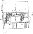
- an electrical enclosure in accordance with an embodiment, is indicated generally with reference numeral 10.
- the electrical enclosure 10 is shown in the form of an electrical switchgear 12 having a housing 14.
- the housing 14 includes a bus bar portion 16 that houses one or more electrical bus bar assemblies. The illustration has a portion of the housing 14 removed to show certain components of the bus bar portion 16 for clarity.
- the bus bar assembly comprises a main bus bar 18 and at least one, but typically a plurality of branch bus bars 20, with each of the branch bus bars 20 providing an electrical conduction path to a fixed contact 22.
- the housing 14 also includes a shutter 24 that provides a selectively moveable barrier between the bus bar portion 16 and a circuit breaker portion 26. The shutter 24, in combination with the housing 14, defines the bus bar portion 16 and the circuit breaker portion 26.
- the branch bus bar 20 is connected to the fixed contact 22.
- the connection may be a direct coupling or may include intermediate mounting components to operatively couple the branch bus bar 20 to the fixed contact 22.
- a cable or cable arrangement may be used to form an electrical conduction path by connection with the fixed contact 22.
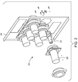
- FIG. 2 a partial disassembled view of the circuit breaker portion 26 is shown, with the perspective taken from an opposite side of the shutter 24 as that illustrated in FIG. 1 . Illustrated is a plurality of spouts 28 that are mounted to the shutter 24 and fit over the fixed contact 22. Each spout facilitates sliding engagement of a sliding contact with the fixed contact 22.
- an electrical path is routed through the joint formed by the components from the bus bar portion 16 to the circuit breaker portion 26 of the electrical switchgear 12.
- a high voltage and current are passed through the fixed contact 22.
- the voltage passing through the fixed contact 22 is about 15,000 Volts and the current passing through the fixed contact 22 is about 2,000 Amps. Due to the high power passing through the fixed contact 22 and associated eddy currents circulating throughout the fixed contact 22, the temperature rise of the fixed contact 22 is a consideration.
- the fixed contact 22 is illustrated in greater detail. As will be appreciated from the description herein, the features of the fixed contact 22 enhance air circulation and reduce operating temperature of the fixed contact 22.
- the fixed contact 22 is disposed about an axis 30 that extends in a longitudinal axial direction of the fixed contact 22.
- the fixed contact 22 comprises a plurality of circumferential segments that are operatively coupled to form the fixed contact 22.
- two segments are included and are referred to as a first segment 32 and a second segment 34.
- more than two circumferential segments may be included and operatively coupled to form the overall fixed contact.
- each segment forms half of the overall fixed segment, but other angular arrangements are contemplated. Irrespective of the precise number of circumferential segments and the angular segment that each comprises, the segments are operatively coupled to each other.
- the coupling may be done with one or more mechanical fasteners 35, such as a non-magnetic bolt.
- the fixed contact 22 Upon coupling the segments together, the fixed contact 22 is formed.
- the entirely formed fixed contact includes distinct regions.
- a mounting contact region 36 extends axially from a first end 38 of the fixed contact 22 to a central region 40 of the fixed contact 22.
- the mounting contact region 36 is the portion of the fixed contact 22 that is coupled to the branch bus bar 20.
- a sliding contact engagement region 42 extends axially from a second end 44 of the fixed contact 22 to the central region 40.
- the sliding contact engagement region 42 is the portion of the fixed contact 22 that is configured to engage the sliding contact in a sliding manner.
- the eddy current fringe is broken due to the breaks in the fixed contact 22. Breaking the eddy current fringe reduces the losses of eddy currents which reduces the heat generated due to eddy current losses.
- a channel 46 is formed at an interior location of the fixed contact 22.
- the channel 46 is defined by the plurality of circumferential segments upon coupling the segments to form the entire fixed contact.
- the channel 46 extends along the axis 30 within at least a portion of the sliding contact engagement region 42. In one embodiment, the channel 46 extends along the entire length of the sliding contact engagement region 42 and it is contemplated that the channel 46 extends further, so as to extend into the mounting contact region 36 of the fixed contact 22.
- additional inner profile features are provided to form additional cooling features of the fixed contact 22.
- at least one, but typically a plurality of slots 48 is formed along inner surfaces of the circumferential segments.
- the slots form at least one, but typically a plurality of apertures 50.
- the plurality of apertures 50 may be formed by each slot itself or by aligning each slot with another slot to form a larger aperture.
- the aperture(s) may be located in various locations along the fixed contact 22.
- one or more exhaust apertures 52 fluidly couple the channel 46 to an external region of the fixed contact 22. Alternatively, or in combination with the exhaust apertures 52, one or more apertures may be formed in portions of the fixed contact 22 where the channel 46 is not present, such as the embodiment shown in FIG. 4 .
- the channel 46 and the plurality of apertures 50 form a cooling network that convectively cools the fixed contact 22 by facilitating the flow of air through interior regions of the fixed contact 22.
- a single segment forms the fixed contact 22, with the channel 46 and apertures machined therein to form the cooling network.
- a significant operating temperature reduction of the fixed contact 22 is achieved. This is done by breaking the eddy current fringe with the breaks in the fixed contact 22, as well as by increasing the surface area of the fixed contact 22 that is subjected to an airflow.
- the channel 46 and plurality of apertures enhance airflow distribution to surfaces of the fixed contact 22 that would not otherwise be subjected to convective cooling.
Landscapes
- Engineering & Computer Science (AREA)
- Power Engineering (AREA)
- Physics & Mathematics (AREA)
- Electromagnetism (AREA)
- Gas-Insulated Switchgears (AREA)
- Arc-Extinguishing Devices That Are Switches (AREA)
Abstract
Description
- The subject matter disclosed herein relates to electrical switchgear assemblies and, more particularly, to a fixed contact for joining a bus bar and a sliding contact.
- A switchgear assembly serves as an interface between an electrical supply and an electrical load. The switchgear is arranged in an enclosure that includes a line or bus bar portion and a load or circuit breaker portion. The bus bar portion includes one or more bus bars that are connected to the electrical supply. The circuit breaker portion includes one or more circuit breakers that are electrically connected to the one or more bus bars and an electrical load. The circuit breaker is configured to interrupt a flow of current from the one or more bus bars to the electrical load in the event of an over-current condition, short circuit condition and/or an over/under voltage condition. Generally, the enclosure includes a shutter that separates the bus bar portion from the circuit breaker portion. Extending through the shutter is a plurality of fixed contacts that are each electrical current path joints that connect to a bus bar at one end and a sliding contact at the other end.
- Due to the high voltage and current being passed through the switchgear, heat is an issue that is to be addressed. The fixed contacts are components that generate a high amount of heat due to high joint resistance. This is due, in part, to eddy current losses within the fixed contacts and challenges associated with cooling the fixed contacts. The heat generated limits the ampacity of the joint, thereby constraining overall switchgear designs and switchgear ratings.
- According to one aspect of the invention, a fixed contact for joining a bus bar and a sliding contact of an electrical switchgear is provided. The fixed contact includes a plurality of circumferential segments operatively coupled to each other. The fixed contact also includes an axial extent extending along a longitudinal axis of the fixed contact from a first end of the fixed contact to a second end of the fixed contact, the axial extent comprising a mounting region, a central region and a sliding contact engagement region. The mounting region extends axially from the first end of the fixed contact to the central region, the mounting region configured to be operatively coupled to the bus bar. The sliding contact engagement region extends axially from the central region to the second end of the fixed contact, the sliding contact region configured to be slidably engaged with a sliding contact.
- According to another aspect of the invention, an electrical switchgear includes a housing and a shutter disposed within the housing and separating the electrical switchgear into a bus bar portion and a circuit breaker portion. Also included is an electrical conductor located within the bus bar portion. Further included is a sliding contact located within the circuit breaker portion. Yet further included is a fixed contact electrically connecting the electrical conductor and the sliding contact, the fixed contact extending through the shutter. The fixed contact includes an axial extent extending along a longitudinal axis of the fixed contact from a first end of the fixed contact to a second end of the fixed contact, the axial extent comprising a mounting region, a central region and a sliding contact engagement region. The mounting region extends axially from the first end of the fixed contact to the central region, the mounting region configured to be operatively coupled to the electrical conductor. The sliding contact engagement region extends axially from the central region to the second end of the fixed contact, the sliding contact region configured to be slidably engaged with the sliding contact. The fixed contact further includes a channel extending along the sliding contact engagement region and defined by the fixed contact.
- These and other advantages and features will become more apparent from the following description taken in conjunction with the drawings.
- The subject matter, which is regarded as the invention, is particularly pointed out and distinctly claimed in the claims at the conclusion of the specification. The foregoing and other features, and advantages of the invention are apparent from the following detailed description taken in conjunction with the accompanying drawings in which:
-
FIG. 1 is a perspective view of an electrical switchgear; -
FIG. 2 is a perspective, partially disassembled view of a portion of a circuit breaker portion of the electrical switchgear illustrating a fixed contact and a spout for connecting a sliding contact thereto; -
FIG. 3 is a perspective view of the fixed contact; and -
FIG. 4 is a perspective view of the fixed contact in a disassembled view to illustrate a plurality of circumferential segments of the fixed contact. - The detailed description explains embodiments of the invention, together with advantages and features, by way of example with reference to the drawings.
- Referring to
FIG. 1 , an electrical enclosure, in accordance with an embodiment, is indicated generally withreference numeral 10. Theelectrical enclosure 10 is shown in the form of anelectrical switchgear 12 having ahousing 14. Thehousing 14 includes abus bar portion 16 that houses one or more electrical bus bar assemblies. The illustration has a portion of thehousing 14 removed to show certain components of thebus bar portion 16 for clarity. The bus bar assembly comprises amain bus bar 18 and at least one, but typically a plurality ofbranch bus bars 20, with each of thebranch bus bars 20 providing an electrical conduction path to a fixedcontact 22. Thehousing 14 also includes ashutter 24 that provides a selectively moveable barrier between thebus bar portion 16 and acircuit breaker portion 26. Theshutter 24, in combination with thehousing 14, defines thebus bar portion 16 and thecircuit breaker portion 26. - As shown, the
branch bus bar 20 is connected to the fixedcontact 22. The connection may be a direct coupling or may include intermediate mounting components to operatively couple thebranch bus bar 20 to the fixedcontact 22. As a non-limiting alternative, a cable or cable arrangement may be used to form an electrical conduction path by connection with the fixedcontact 22. - Referring now to
FIG. 2 , a partial disassembled view of thecircuit breaker portion 26 is shown, with the perspective taken from an opposite side of theshutter 24 as that illustrated inFIG. 1 . Illustrated is a plurality ofspouts 28 that are mounted to theshutter 24 and fit over the fixedcontact 22. Each spout facilitates sliding engagement of a sliding contact with the fixedcontact 22. Upon connection of the fixedcontact 22 to thebranch bus bar 20 and the sliding contact, an electrical path is routed through the joint formed by the components from thebus bar portion 16 to thecircuit breaker portion 26 of theelectrical switchgear 12. - Typically, a high voltage and current are passed through the fixed
contact 22. By way of a non-limiting example, the voltage passing through the fixedcontact 22 is about 15,000 Volts and the current passing through the fixedcontact 22 is about 2,000 Amps. Due to the high power passing through the fixedcontact 22 and associated eddy currents circulating throughout the fixedcontact 22, the temperature rise of the fixedcontact 22 is a consideration. - Referring to
FIGS. 3 and 4 , the fixedcontact 22 is illustrated in greater detail. As will be appreciated from the description herein, the features of the fixedcontact 22 enhance air circulation and reduce operating temperature of the fixedcontact 22. - The fixed
contact 22 is disposed about anaxis 30 that extends in a longitudinal axial direction of the fixedcontact 22. The fixedcontact 22 comprises a plurality of circumferential segments that are operatively coupled to form the fixedcontact 22. In the illustrated non-limiting embodiment, two segments are included and are referred to as afirst segment 32 and asecond segment 34. It is to be appreciated that more than two circumferential segments may be included and operatively coupled to form the overall fixed contact. In the illustrated embodiment with thefirst segment 32 and thesecond segment 34, each segment forms half of the overall fixed segment, but other angular arrangements are contemplated. Irrespective of the precise number of circumferential segments and the angular segment that each comprises, the segments are operatively coupled to each other. The coupling may be done with one or moremechanical fasteners 35, such as a non-magnetic bolt. - Upon coupling the segments together, the fixed
contact 22 is formed. The entirely formed fixed contact includes distinct regions. A mountingcontact region 36 extends axially from afirst end 38 of the fixedcontact 22 to acentral region 40 of the fixedcontact 22. The mountingcontact region 36 is the portion of the fixedcontact 22 that is coupled to thebranch bus bar 20. A slidingcontact engagement region 42 extends axially from asecond end 44 of the fixedcontact 22 to thecentral region 40. The slidingcontact engagement region 42 is the portion of the fixedcontact 22 that is configured to engage the sliding contact in a sliding manner. - As described above, heating of the fixed
contact 22 is a consideration. By splitting the fixedcontact 22 into a plurality of circumferential segments, the eddy current fringe is broken due to the breaks in the fixedcontact 22. Breaking the eddy current fringe reduces the losses of eddy currents which reduces the heat generated due to eddy current losses. - In addition to breaking the eddy current fringe, to improve air circulation and overall cooling within the fixed
contact 22, achannel 46 is formed at an interior location of the fixedcontact 22. Thechannel 46 is defined by the plurality of circumferential segments upon coupling the segments to form the entire fixed contact. Thechannel 46 extends along theaxis 30 within at least a portion of the slidingcontact engagement region 42. In one embodiment, thechannel 46 extends along the entire length of the slidingcontact engagement region 42 and it is contemplated that thechannel 46 extends further, so as to extend into the mountingcontact region 36 of the fixedcontact 22. - In addition to the formation of the
channel 46 with the inner profiles of the circumferential segments, additional inner profile features are provided to form additional cooling features of the fixedcontact 22. In particular, at least one, but typically a plurality ofslots 48 is formed along inner surfaces of the circumferential segments. Upon coupling of the circumferential segments, the slots form at least one, but typically a plurality ofapertures 50. The plurality ofapertures 50 may be formed by each slot itself or by aligning each slot with another slot to form a larger aperture. The aperture(s) may be located in various locations along the fixedcontact 22. In one embodiment, one or more exhaust apertures 52 fluidly couple thechannel 46 to an external region of the fixedcontact 22. Alternatively, or in combination with the exhaust apertures 52, one or more apertures may be formed in portions of the fixedcontact 22 where thechannel 46 is not present, such as the embodiment shown inFIG. 4 . - The
channel 46 and the plurality ofapertures 50 form a cooling network that convectively cools the fixedcontact 22 by facilitating the flow of air through interior regions of the fixedcontact 22. Although described as a plurality of circumferential segments, it is contemplated that a single segment forms the fixedcontact 22, with thechannel 46 and apertures machined therein to form the cooling network. - Advantageously, in embodiments having a plurality of circumferential segments and the cooling network described in detail above, a significant operating temperature reduction of the fixed
contact 22 is achieved. This is done by breaking the eddy current fringe with the breaks in the fixedcontact 22, as well as by increasing the surface area of the fixedcontact 22 that is subjected to an airflow. Thechannel 46 and plurality of apertures enhance airflow distribution to surfaces of the fixedcontact 22 that would not otherwise be subjected to convective cooling. - While the invention has been described in detail in connection with only a limited number of embodiments, it should be readily understood that the invention is not limited to such disclosed embodiments. Rather, the invention can be modified to incorporate any number of variations, alterations, substitutions or equivalent arrangements not heretofore described, but which are commensurate with the spirit and scope of the invention. Additionally, while various embodiments of the invention have been described, it is to be understood that aspects of the invention may include only some of the described embodiments. Accordingly, the invention is not to be seen as limited by the foregoing description, but is only limited by the scope of the appended claims.
- Various aspects and embodiments of the present invention are defined by the following numbered clauses:
- 1. A fixed contact for joining a bus bar and a sliding contact of an electrical switchgear comprising:
- a plurality of circumferential segments operatively coupled to each other;
- the fixed contact having an axial extent extending along a longitudinal axis of the fixed contact from a first end of the fixed contact to a second end of the fixed contact, the axial extent comprising a mounting region, a central region and a sliding contact engagement region;
- the mounting region extending axially from the first end of the fixed contact to the central region, the mounting region configured to be operatively coupled to the bus bar; and
- the sliding contact engagement region extending axially from the central region to the second end of the fixed contact, the sliding contact region configured to be slidably engaged with a sliding contact.
- 2. The fixed contact of clause 1, further comprising a channel defined by the plurality of circumferential segments.
- 3. The fixed contact of any preceding clause, the channel extending along a portion of the sliding contact engagement region.
- 4. The fixed contact of any preceding clause, the channel extending along an entire length of the sliding contact region.
- 5. The fixed contact of any preceding clause, further comprising at least one exhaust aperture fluidly coupling the channel to an external region of the fixed contact.
- 6. The fixed contact of any preceding clause, the plurality of circumferential segments operatively coupled to each other with at least one non-magnetic mechanical fastener.
- 7. The fixed contact of any preceding clause, the plurality of circumferential segments comprising a first segment and a second segment.
- 8. The fixed contact of any preceding clause, wherein the first segment and the second segment each form half of the fixed contact.
- 9. The fixed contact of any preceding clause, further comprising a plurality of slots formed in the first segment and the second segment, each of the plurality of slots of the first segment aligned with a corresponding slot of the second segment to define a plurality of apertures when the first segment and the second segment are operatively coupled.
- 10. An electrical switchgear comprising:
- a housing;
- a shutter disposed within the housing and separating the electrical switchgear into a bus bar portion and a circuit breaker portion;
- an electrical conductor located within the bus bar portion;
- a sliding contact located within the circuit breaker portion; and
- a fixed contact electrically connecting the electrical conductor and the sliding contact, the fixed contact extending through the shutter and comprising:
- the fixed contact having an axial extent extending from a first end of the fixed contact to a second end of the fixed contact, the axial extent comprising a mounting region, a central region and a sliding contact engagement region;
- the mounting region extending axially from the first end of the fixed contact to the central region, the mounting region configured to be operatively coupled to the bus bar electrical conductor;
- the sliding contact engagement region extending axially from the central region to the second end of the fixed contact, the sliding contact region configured to be slidably engaged with the sliding contact; and
- a channel extending along the sliding contact engagement region and defined by the fixed contact.
- 11. The electrical switchgear of any preceding clause, the fixed contact comprising a plurality of circumferential segments operatively coupled to each other, the channel defined by the plurality of circumferential segments.
- 12. The electrical switchgear of any preceding clause, the plurality of circumferential segments comprising a first segment and a second segment.
- 13. The electrical switchgear of any preceding clause, wherein the first segment and the second segment each form half of the fixed contact.
- 14. The electrical switchgear of any preceding clause, further comprising a plurality of slots formed in the first segment and the second segment, each of the plurality of slots of the first segment aligned with a corresponding slot of the second segment to define a plurality of apertures when the first segment and the second segment are operatively coupled.
- 15. The electrical switchgear of any preceding clause, the plurality of circumferential segments operatively coupled to each other with at least one non-magnetic mechanical fastener.
- 16. The electrical switchgear of any preceding clause, the channel extending along a portion of the sliding contact engagement region.
- 17. The electrical switchgear of any preceding clause, the channel extending along an entire length of the sliding contact region.
- 18. The electrical switchgear of any preceding clause, further comprising at least one exhaust aperture fluidly coupling the channel to an external region of the fixed contact.
- 19. The electrical switchgear of any preceding clause, wherein the electrical conductor comprises a bus bar.
- 20. The electrical switchgear of any preceding clause, wherein the electrical conductor comprises at least one cable.
Claims (15)
- A fixed contact (22) for joining a bus bar and a sliding contact of an electrical switchgear (12) comprising:a plurality of circumferential segments (32, 34) operatively coupled to each other;the fixed contact having an axial extent extending along a longitudinal axis (30) of the fixed contact from a first end (38) of the fixed contact to a second end (44) of the fixed contact, the axial extent comprising a mounting region (36), a central region (40) and a sliding contact engagement region (42);the mounting region extending axially from the first end of the fixed contact to the central region, the mounting region configured to be operatively coupled to the bus bar; andthe sliding contact engagement region extending axially from the central region to the second end of the fixed contact, the sliding contact region configured to be slidably engaged with a sliding contact.
- The fixed contact of claim 1, further comprising a channel (46) defined by the plurality of circumferential segments.
- The fixed contact of claim 2, the channel extending along a portion of the sliding contact engagement region.
- The fixed contact of claim 2, the channel extending along an entire length of the sliding contact region.
- The fixed contact of claim 2, 3 or 4, further comprising at least one exhaust aperture (52) fluidly coupling the channel to an external region of the fixed contact.
- The fixed contact of any preceding claim, the plurality of circumferential segments operatively coupled to each other with at least one non-magnetic mechanical fastener.
- The fixed contact of any preceding claim, the plurality of circumferential segments comprising a first segment (32) and a second segment (34).
- The fixed contact of claim 7, wherein the first segment and the second segment each form half of the fixed contact.
- The fixed contact of claim 7 or 8, further comprising a plurality of slots (48) formed in the first segment and the second segment, each of the plurality of slots of the first segment aligned with a corresponding slot of the second segment to define a plurality of apertures when the first segment and the second segment are operatively coupled.
- An electrical switchgear (12) comprising:a housing (14);a shutter (24) disposed within the housing and separating the electrical switchgear into a bus bar portion (16) and a circuit breaker portion (26);an electrical conductor located within the bus bar portion;a sliding contact located within the circuit breaker portion; anda fixed contact (22) electrically connecting the electrical conductor and the sliding contact, the fixed contact extending through the shutter and comprising:the fixed contact having an axial extent extending from a first end (38) of the fixed contact to a second end (44) of the fixed contact, the axial extent comprising a mounting region (36), a central region (40) and a sliding contact engagement region (42);the mounting region extending axially from the first end of the fixed contact to the central region, the mounting region configured to be operatively coupled to the bus bar electrical conductor;the sliding contact engagement region extending axially from the central region to the second end of the fixed contact, the sliding contact region configured to be slidably engaged with the sliding contact; anda channel (46) extending along the sliding contact engagement region and defined by the fixed contact.
- The electrical switchgear of claim 10, the fixed contact comprising a plurality of circumferential segments operatively coupled to each other, the channel defined by the plurality of circumferential segments.
- The electrical switchgear of claim 11, the plurality of circumferential segments comprising a first segment and a second segment.
- The electrical switchgear of claim 12, wherein the first segment and the second segment each form half of the fixed contact.
- The electrical switchgear of claim 12 or 13, further comprising a plurality of slots formed in the first segment and the second segment, each of the plurality of slots of the first segment aligned with a corresponding slot of the second segment to define a plurality of apertures when the first segment and the second segment are operatively coupled.
- The electrical switchgear of any of claims 1 to 14, the plurality of circumferential segments operatively coupled to each other with at least one non-magnetic mechanical fastener.
Applications Claiming Priority (1)
| Application Number | Priority Date | Filing Date | Title |
|---|---|---|---|
| US14/613,003 US9865405B2 (en) | 2015-02-03 | 2015-02-03 | Fixed contact for joining a bus bar and a sliding contact of an electrical switchgear |
Publications (2)
| Publication Number | Publication Date |
|---|---|
| EP3054471A1 true EP3054471A1 (en) | 2016-08-10 |
| EP3054471B1 EP3054471B1 (en) | 2019-05-15 |
Family
ID=55237609
Family Applications (1)
| Application Number | Title | Priority Date | Filing Date |
|---|---|---|---|
| EP16153120.7A Active EP3054471B1 (en) | 2015-02-03 | 2016-01-28 | Fixed contact for joining a bus bar and a sliding contact of an electrical switchgear |
Country Status (3)
| Country | Link |
|---|---|
| US (1) | US9865405B2 (en) |
| EP (1) | EP3054471B1 (en) |
| CN (1) | CN105845466B (en) |
Families Citing this family (2)
| Publication number | Priority date | Publication date | Assignee | Title |
|---|---|---|---|---|
| USD832222S1 (en) * | 2016-09-26 | 2018-10-30 | Switchboard Apparatus, Inc. | Insulator |
| US12087523B2 (en) | 2020-12-07 | 2024-09-10 | G & W Electric Company | Solid dielectric insulated switchgear |
Citations (2)
| Publication number | Priority date | Publication date | Assignee | Title |
|---|---|---|---|---|
| US2824939A (en) * | 1955-03-17 | 1958-02-25 | Westinghouse Electric Corp | Cooling means for metal-clad switchgear |
| US20140368976A1 (en) * | 2013-06-13 | 2014-12-18 | General Electric Company | Spout for switchgear, switchgear having spout, and method thereof |
Family Cites Families (13)
| Publication number | Priority date | Publication date | Assignee | Title |
|---|---|---|---|---|
| US3603753A (en) | 1968-02-28 | 1971-09-07 | Westinghouse Electric Corp | Metalclad switchgear using vacuum interrupter elements |
| US3612799A (en) | 1969-05-08 | 1971-10-12 | Ite Imperial Corp | Gas blast circuit interrupter using main movable contact as blast valve |
| JP2002124162A (en) | 2000-10-16 | 2002-04-26 | Mitsubishi Electric Corp | Switchgear |
| EP1939910A1 (en) | 2006-12-27 | 2008-07-02 | ABB Technology AG | Gas blast circuit breaker with a radial flow opening |
| CN201048090Y (en) | 2007-05-25 | 2008-04-16 | 毕新华 | Split type stationary contact |
| JP5127569B2 (en) | 2008-05-29 | 2013-01-23 | 株式会社東芝 | Gas insulated switch |
| CN201219183Y (en) | 2008-07-02 | 2009-04-08 | 厦门华电开关有限公司 | Large current and medium voltage switch cabinet |
| CN201444453U (en) * | 2009-08-04 | 2010-04-28 | 益和电气集团股份有限公司 | Novel conductive connecting device |
| KR101158652B1 (en) * | 2011-02-09 | 2012-06-26 | 엘에스산전 주식회사 | Vacuum circuit breaker |
| EP2551869A1 (en) * | 2011-07-25 | 2013-01-30 | ABB Technology AG | Power distribution switchgear circuit breaker |
| KR101199588B1 (en) | 2011-08-24 | 2012-11-12 | 현대중공업 주식회사 | Apparatus for dual-couple contact in gas insulated switchgear |
| CN202524000U (en) | 2012-04-16 | 2012-11-07 | 河南新开电气集团股份有限公司 | Temperature rise reducing device of fixed contact of drawing-out type high-voltage switch cabinet |
| CN202695163U (en) | 2012-05-22 | 2013-01-23 | 北京北开电气股份有限公司 | Three-position movable contact base assembling structure for box-type gas insulated metal-enclosed switchgears |
-
2015
- 2015-02-03 US US14/613,003 patent/US9865405B2/en active Active
-
2016
- 2016-01-28 EP EP16153120.7A patent/EP3054471B1/en active Active
- 2016-02-01 CN CN201610068034.3A patent/CN105845466B/en active Active
Patent Citations (2)
| Publication number | Priority date | Publication date | Assignee | Title |
|---|---|---|---|---|
| US2824939A (en) * | 1955-03-17 | 1958-02-25 | Westinghouse Electric Corp | Cooling means for metal-clad switchgear |
| US20140368976A1 (en) * | 2013-06-13 | 2014-12-18 | General Electric Company | Spout for switchgear, switchgear having spout, and method thereof |
Also Published As
| Publication number | Publication date |
|---|---|
| US9865405B2 (en) | 2018-01-09 |
| CN105845466B (en) | 2019-12-27 |
| EP3054471B1 (en) | 2019-05-15 |
| US20160225545A1 (en) | 2016-08-04 |
| CN105845466A (en) | 2016-08-10 |
Similar Documents
| Publication | Publication Date | Title |
|---|---|---|
| US10230221B2 (en) | Spout for switchgear, switchgear having spout, and method thereof | |
| US8362665B2 (en) | Liquid cooled stator terminal block for an electric machine | |
| EP3054471B1 (en) | Fixed contact for joining a bus bar and a sliding contact of an electrical switchgear | |
| CN107112151B (en) | Electrical systems, electrical switchgear and their protective components | |
| US10405460B2 (en) | Circuit breaker arrangements | |
| CN102971925B (en) | For the connecting element of switchgear and associated component and this switchgear | |
| US9147541B2 (en) | Circuit breaker comprising ventilation channels for efficient heat dissipation | |
| KR20160002213U (en) | Common Busbar for DC Modlede Case Circuit Breaker | |
| JP2006166651A (en) | Switchgear | |
| CN102017039A (en) | Heat dissipating means for circuit-breaker and circuit-breaker with such heat dissipating means | |
| KR101135207B1 (en) | Gas Insulated Bus | |
| JP7689280B2 (en) | Breaker | |
| US10134553B2 (en) | Contact arms for use in electrical switchgear and methods of fabricating same | |
| KR20130011008A (en) | Bus bar assembly of distributing equipment | |
| KR200488177Y1 (en) | Earthing Switch of GIS | |
| BR102015010050A2 (en) | brush plate for a brush type electric motor | |
| US9595799B2 (en) | Electrical enclosure having a dual bus bar and a component with a dual bus bar connector | |
| KR101463046B1 (en) | The Terminal of Cradle for Withdrawable Circuit Breaker | |
| KR20120024500A (en) | Current-carrying segment, method for cooling thereof and electrical apparatus | |
| US20170263398A1 (en) | Gas circuit breaker | |
| CN104170045B (en) | Switchgear for Electric Power | |
| JP2009152149A (en) | Terminal block | |
| CN204559406U (en) | Converter assembly | |
| KR20120103134A (en) | Gas insulated switchgear with shape memory alloy | |
| KR100967945B1 (en) | Metal enclosed switchboard |
Legal Events
| Date | Code | Title | Description |
|---|---|---|---|
| PUAI | Public reference made under article 153(3) epc to a published international application that has entered the european phase |
Free format text: ORIGINAL CODE: 0009012 |
|
| AK | Designated contracting states |
Kind code of ref document: A1 Designated state(s): AL AT BE BG CH CY CZ DE DK EE ES FI FR GB GR HR HU IE IS IT LI LT LU LV MC MK MT NL NO PL PT RO RS SE SI SK SM TR |
|
| AX | Request for extension of the european patent |
Extension state: BA ME |
|
| STAA | Information on the status of an ep patent application or granted ep patent |
Free format text: STATUS: REQUEST FOR EXAMINATION WAS MADE |
|
| 17P | Request for examination filed |
Effective date: 20170210 |
|
| RBV | Designated contracting states (corrected) |
Designated state(s): AL AT BE BG CH CY CZ DE DK EE ES FI FR GB GR HR HU IE IS IT LI LT LU LV MC MK MT NL NO PL PT RO RS SE SI SK SM TR |
|
| GRAP | Despatch of communication of intention to grant a patent |
Free format text: ORIGINAL CODE: EPIDOSNIGR1 |
|
| STAA | Information on the status of an ep patent application or granted ep patent |
Free format text: STATUS: GRANT OF PATENT IS INTENDED |
|
| RIC1 | Information provided on ipc code assigned before grant |
Ipc: H02G 5/10 20060101ALI20181025BHEP Ipc: H01H 33/66 20060101ALN20181025BHEP Ipc: H02B 11/04 20060101ALI20181025BHEP Ipc: H02B 1/56 20060101ALN20181025BHEP Ipc: H01H 33/02 20060101AFI20181025BHEP Ipc: H01H 1/62 20060101ALI20181025BHEP |
|
| INTG | Intention to grant announced |
Effective date: 20181123 |
|
| GRAS | Grant fee paid |
Free format text: ORIGINAL CODE: EPIDOSNIGR3 |
|
| GRAA | (expected) grant |
Free format text: ORIGINAL CODE: 0009210 |
|
| STAA | Information on the status of an ep patent application or granted ep patent |
Free format text: STATUS: THE PATENT HAS BEEN GRANTED |
|
| RAP1 | Party data changed (applicant data changed or rights of an application transferred) |
Owner name: ABB SCHWEIZ AG |
|
| AK | Designated contracting states |
Kind code of ref document: B1 Designated state(s): AL AT BE BG CH CY CZ DE DK EE ES FI FR GB GR HR HU IE IS IT LI LT LU LV MC MK MT NL NO PL PT RO RS SE SI SK SM TR |
|
| REG | Reference to a national code |
Ref country code: CH Ref legal event code: EP |
|
| REG | Reference to a national code |
Ref country code: DE Ref legal event code: R096 Ref document number: 602016013846 Country of ref document: DE |
|
| REG | Reference to a national code |
Ref country code: IE Ref legal event code: FG4D |
|
| REG | Reference to a national code |
Ref country code: NL Ref legal event code: MP Effective date: 20190515 |
|
| REG | Reference to a national code |
Ref country code: LT Ref legal event code: MG4D |
|
| PG25 | Lapsed in a contracting state [announced via postgrant information from national office to epo] |
Ref country code: ES Free format text: LAPSE BECAUSE OF FAILURE TO SUBMIT A TRANSLATION OF THE DESCRIPTION OR TO PAY THE FEE WITHIN THE PRESCRIBED TIME-LIMIT Effective date: 20190515 Ref country code: PT Free format text: LAPSE BECAUSE OF FAILURE TO SUBMIT A TRANSLATION OF THE DESCRIPTION OR TO PAY THE FEE WITHIN THE PRESCRIBED TIME-LIMIT Effective date: 20190915 Ref country code: SE Free format text: LAPSE BECAUSE OF FAILURE TO SUBMIT A TRANSLATION OF THE DESCRIPTION OR TO PAY THE FEE WITHIN THE PRESCRIBED TIME-LIMIT Effective date: 20190515 Ref country code: NL Free format text: LAPSE BECAUSE OF FAILURE TO SUBMIT A TRANSLATION OF THE DESCRIPTION OR TO PAY THE FEE WITHIN THE PRESCRIBED TIME-LIMIT Effective date: 20190515 Ref country code: AL Free format text: LAPSE BECAUSE OF FAILURE TO SUBMIT A TRANSLATION OF THE DESCRIPTION OR TO PAY THE FEE WITHIN THE PRESCRIBED TIME-LIMIT Effective date: 20190515 Ref country code: NO Free format text: LAPSE BECAUSE OF FAILURE TO SUBMIT A TRANSLATION OF THE DESCRIPTION OR TO PAY THE FEE WITHIN THE PRESCRIBED TIME-LIMIT Effective date: 20190815 Ref country code: FI Free format text: LAPSE BECAUSE OF FAILURE TO SUBMIT A TRANSLATION OF THE DESCRIPTION OR TO PAY THE FEE WITHIN THE PRESCRIBED TIME-LIMIT Effective date: 20190515 Ref country code: LT Free format text: LAPSE BECAUSE OF FAILURE TO SUBMIT A TRANSLATION OF THE DESCRIPTION OR TO PAY THE FEE WITHIN THE PRESCRIBED TIME-LIMIT Effective date: 20190515 Ref country code: HR Free format text: LAPSE BECAUSE OF FAILURE TO SUBMIT A TRANSLATION OF THE DESCRIPTION OR TO PAY THE FEE WITHIN THE PRESCRIBED TIME-LIMIT Effective date: 20190515 |
|
| PG25 | Lapsed in a contracting state [announced via postgrant information from national office to epo] |
Ref country code: GR Free format text: LAPSE BECAUSE OF FAILURE TO SUBMIT A TRANSLATION OF THE DESCRIPTION OR TO PAY THE FEE WITHIN THE PRESCRIBED TIME-LIMIT Effective date: 20190816 Ref country code: LV Free format text: LAPSE BECAUSE OF FAILURE TO SUBMIT A TRANSLATION OF THE DESCRIPTION OR TO PAY THE FEE WITHIN THE PRESCRIBED TIME-LIMIT Effective date: 20190515 Ref country code: BG Free format text: LAPSE BECAUSE OF FAILURE TO SUBMIT A TRANSLATION OF THE DESCRIPTION OR TO PAY THE FEE WITHIN THE PRESCRIBED TIME-LIMIT Effective date: 20190815 Ref country code: RS Free format text: LAPSE BECAUSE OF FAILURE TO SUBMIT A TRANSLATION OF THE DESCRIPTION OR TO PAY THE FEE WITHIN THE PRESCRIBED TIME-LIMIT Effective date: 20190515 |
|
| REG | Reference to a national code |
Ref country code: AT Ref legal event code: MK05 Ref document number: 1134408 Country of ref document: AT Kind code of ref document: T Effective date: 20190515 |
|
| PG25 | Lapsed in a contracting state [announced via postgrant information from national office to epo] |
Ref country code: AT Free format text: LAPSE BECAUSE OF FAILURE TO SUBMIT A TRANSLATION OF THE DESCRIPTION OR TO PAY THE FEE WITHIN THE PRESCRIBED TIME-LIMIT Effective date: 20190515 Ref country code: DK Free format text: LAPSE BECAUSE OF FAILURE TO SUBMIT A TRANSLATION OF THE DESCRIPTION OR TO PAY THE FEE WITHIN THE PRESCRIBED TIME-LIMIT Effective date: 20190515 Ref country code: EE Free format text: LAPSE BECAUSE OF FAILURE TO SUBMIT A TRANSLATION OF THE DESCRIPTION OR TO PAY THE FEE WITHIN THE PRESCRIBED TIME-LIMIT Effective date: 20190515 Ref country code: CZ Free format text: LAPSE BECAUSE OF FAILURE TO SUBMIT A TRANSLATION OF THE DESCRIPTION OR TO PAY THE FEE WITHIN THE PRESCRIBED TIME-LIMIT Effective date: 20190515 Ref country code: SK Free format text: LAPSE BECAUSE OF FAILURE TO SUBMIT A TRANSLATION OF THE DESCRIPTION OR TO PAY THE FEE WITHIN THE PRESCRIBED TIME-LIMIT Effective date: 20190515 |
|
| REG | Reference to a national code |
Ref country code: DE Ref legal event code: R097 Ref document number: 602016013846 Country of ref document: DE |
|
| PG25 | Lapsed in a contracting state [announced via postgrant information from national office to epo] |
Ref country code: SM Free format text: LAPSE BECAUSE OF FAILURE TO SUBMIT A TRANSLATION OF THE DESCRIPTION OR TO PAY THE FEE WITHIN THE PRESCRIBED TIME-LIMIT Effective date: 20190515 |
|
| PLBE | No opposition filed within time limit |
Free format text: ORIGINAL CODE: 0009261 |
|
| STAA | Information on the status of an ep patent application or granted ep patent |
Free format text: STATUS: NO OPPOSITION FILED WITHIN TIME LIMIT |
|
| PG25 | Lapsed in a contracting state [announced via postgrant information from national office to epo] |
Ref country code: TR Free format text: LAPSE BECAUSE OF FAILURE TO SUBMIT A TRANSLATION OF THE DESCRIPTION OR TO PAY THE FEE WITHIN THE PRESCRIBED TIME-LIMIT Effective date: 20190515 |
|
| 26N | No opposition filed |
Effective date: 20200218 |
|
| PG25 | Lapsed in a contracting state [announced via postgrant information from national office to epo] |
Ref country code: PL Free format text: LAPSE BECAUSE OF FAILURE TO SUBMIT A TRANSLATION OF THE DESCRIPTION OR TO PAY THE FEE WITHIN THE PRESCRIBED TIME-LIMIT Effective date: 20190515 |
|
| PG25 | Lapsed in a contracting state [announced via postgrant information from national office to epo] |
Ref country code: SI Free format text: LAPSE BECAUSE OF FAILURE TO SUBMIT A TRANSLATION OF THE DESCRIPTION OR TO PAY THE FEE WITHIN THE PRESCRIBED TIME-LIMIT Effective date: 20190515 |
|
| REG | Reference to a national code |
Ref country code: DE Ref legal event code: R119 Ref document number: 602016013846 Country of ref document: DE |
|
| PG25 | Lapsed in a contracting state [announced via postgrant information from national office to epo] |
Ref country code: MC Free format text: LAPSE BECAUSE OF FAILURE TO SUBMIT A TRANSLATION OF THE DESCRIPTION OR TO PAY THE FEE WITHIN THE PRESCRIBED TIME-LIMIT Effective date: 20190515 |
|
| REG | Reference to a national code |
Ref country code: CH Ref legal event code: PL |
|
| GBPC | Gb: european patent ceased through non-payment of renewal fee |
Effective date: 20200128 |
|
| REG | Reference to a national code |
Ref country code: BE Ref legal event code: MM Effective date: 20200131 |
|
| PG25 | Lapsed in a contracting state [announced via postgrant information from national office to epo] |
Ref country code: FR Free format text: LAPSE BECAUSE OF NON-PAYMENT OF DUE FEES Effective date: 20200131 Ref country code: LU Free format text: LAPSE BECAUSE OF NON-PAYMENT OF DUE FEES Effective date: 20200128 Ref country code: GB Free format text: LAPSE BECAUSE OF NON-PAYMENT OF DUE FEES Effective date: 20200128 Ref country code: DE Free format text: LAPSE BECAUSE OF NON-PAYMENT OF DUE FEES Effective date: 20200801 |
|
| PG25 | Lapsed in a contracting state [announced via postgrant information from national office to epo] |
Ref country code: LI Free format text: LAPSE BECAUSE OF NON-PAYMENT OF DUE FEES Effective date: 20200131 Ref country code: BE Free format text: LAPSE BECAUSE OF NON-PAYMENT OF DUE FEES Effective date: 20200131 Ref country code: CH Free format text: LAPSE BECAUSE OF NON-PAYMENT OF DUE FEES Effective date: 20200131 |
|
| PG25 | Lapsed in a contracting state [announced via postgrant information from national office to epo] |
Ref country code: IE Free format text: LAPSE BECAUSE OF NON-PAYMENT OF DUE FEES Effective date: 20200128 Ref country code: IT Free format text: LAPSE BECAUSE OF NON-PAYMENT OF DUE FEES Effective date: 20200128 |
|
| PG25 | Lapsed in a contracting state [announced via postgrant information from national office to epo] |
Ref country code: MT Free format text: LAPSE BECAUSE OF FAILURE TO SUBMIT A TRANSLATION OF THE DESCRIPTION OR TO PAY THE FEE WITHIN THE PRESCRIBED TIME-LIMIT Effective date: 20190515 Ref country code: CY Free format text: LAPSE BECAUSE OF FAILURE TO SUBMIT A TRANSLATION OF THE DESCRIPTION OR TO PAY THE FEE WITHIN THE PRESCRIBED TIME-LIMIT Effective date: 20190515 |
|
| PG25 | Lapsed in a contracting state [announced via postgrant information from national office to epo] |
Ref country code: RO Free format text: LAPSE BECAUSE OF FAILURE TO SUBMIT A TRANSLATION OF THE DESCRIPTION OR TO PAY THE FEE WITHIN THE PRESCRIBED TIME-LIMIT Effective date: 20190515 Ref country code: MK Free format text: LAPSE BECAUSE OF FAILURE TO SUBMIT A TRANSLATION OF THE DESCRIPTION OR TO PAY THE FEE WITHIN THE PRESCRIBED TIME-LIMIT Effective date: 20190515 Ref country code: IS Free format text: LAPSE BECAUSE OF FAILURE TO SUBMIT A TRANSLATION OF THE DESCRIPTION OR TO PAY THE FEE WITHIN THE PRESCRIBED TIME-LIMIT Effective date: 20190915 |