EP3054411A1 - Work machine position information management system - Google Patents
Work machine position information management system Download PDFInfo
- Publication number
- EP3054411A1 EP3054411A1 EP14850214.9A EP14850214A EP3054411A1 EP 3054411 A1 EP3054411 A1 EP 3054411A1 EP 14850214 A EP14850214 A EP 14850214A EP 3054411 A1 EP3054411 A1 EP 3054411A1
- Authority
- EP
- European Patent Office
- Prior art keywords
- work
- position information
- crane
- machine
- transmission controller
- Prior art date
- Legal status (The legal status is an assumption and is not a legal conclusion. Google has not performed a legal analysis and makes no representation as to the accuracy of the status listed.)
- Withdrawn
Links
Images

Classifications
-
- G—PHYSICS
- G07—CHECKING-DEVICES
- G07C—TIME OR ATTENDANCE REGISTERS; REGISTERING OR INDICATING THE WORKING OF MACHINES; GENERATING RANDOM NUMBERS; VOTING OR LOTTERY APPARATUS; ARRANGEMENTS, SYSTEMS OR APPARATUS FOR CHECKING NOT PROVIDED FOR ELSEWHERE
- G07C5/00—Registering or indicating the working of vehicles
- G07C5/008—Registering or indicating the working of vehicles communicating information to a remotely located station
-
- B—PERFORMING OPERATIONS; TRANSPORTING
- B66—HOISTING; LIFTING; HAULING
- B66C—CRANES; LOAD-ENGAGING ELEMENTS OR DEVICES FOR CRANES, CAPSTANS, WINCHES, OR TACKLES
- B66C13/00—Other constructional features or details
- B66C13/18—Control systems or devices
- B66C13/46—Position indicators for suspended loads or for crane elements
-
- B—PERFORMING OPERATIONS; TRANSPORTING
- B66—HOISTING; LIFTING; HAULING
- B66C—CRANES; LOAD-ENGAGING ELEMENTS OR DEVICES FOR CRANES, CAPSTANS, WINCHES, OR TACKLES
- B66C13/00—Other constructional features or details
- B66C13/16—Applications of indicating, registering, or weighing devices
-
- B—PERFORMING OPERATIONS; TRANSPORTING
- B66—HOISTING; LIFTING; HAULING
- B66C—CRANES; LOAD-ENGAGING ELEMENTS OR DEVICES FOR CRANES, CAPSTANS, WINCHES, OR TACKLES
- B66C15/00—Safety gear
- B66C15/04—Safety gear for preventing collisions, e.g. between cranes or trolleys operating on the same track
- B66C15/045—Safety gear for preventing collisions, e.g. between cranes or trolleys operating on the same track electrical
-
- G—PHYSICS
- G01—MEASURING; TESTING
- G01S—RADIO DIRECTION-FINDING; RADIO NAVIGATION; DETERMINING DISTANCE OR VELOCITY BY USE OF RADIO WAVES; LOCATING OR PRESENCE-DETECTING BY USE OF THE REFLECTION OR RERADIATION OF RADIO WAVES; ANALOGOUS ARRANGEMENTS USING OTHER WAVES
- G01S19/00—Satellite radio beacon positioning systems; Determining position, velocity or attitude using signals transmitted by such systems
- G01S19/01—Satellite radio beacon positioning systems transmitting time-stamped messages, e.g. GPS [Global Positioning System], GLONASS [Global Orbiting Navigation Satellite System] or GALILEO
- G01S19/13—Receivers
-
- G—PHYSICS
- G05—CONTROLLING; REGULATING
- G05B—CONTROL OR REGULATING SYSTEMS IN GENERAL; FUNCTIONAL ELEMENTS OF SUCH SYSTEMS; MONITORING OR TESTING ARRANGEMENTS FOR SUCH SYSTEMS OR ELEMENTS
- G05B15/00—Systems controlled by a computer
- G05B15/02—Systems controlled by a computer electric
-
- G—PHYSICS
- G06—COMPUTING OR CALCULATING; COUNTING
- G06Q—INFORMATION AND COMMUNICATION TECHNOLOGY [ICT] SPECIALLY ADAPTED FOR ADMINISTRATIVE, COMMERCIAL, FINANCIAL, MANAGERIAL OR SUPERVISORY PURPOSES; SYSTEMS OR METHODS SPECIALLY ADAPTED FOR ADMINISTRATIVE, COMMERCIAL, FINANCIAL, MANAGERIAL OR SUPERVISORY PURPOSES, NOT OTHERWISE PROVIDED FOR
- G06Q10/00—Administration; Management
- G06Q10/06—Resources, workflows, human or project management; Enterprise or organisation planning; Enterprise or organisation modelling
-
- G—PHYSICS
- G06—COMPUTING OR CALCULATING; COUNTING
- G06Q—INFORMATION AND COMMUNICATION TECHNOLOGY [ICT] SPECIALLY ADAPTED FOR ADMINISTRATIVE, COMMERCIAL, FINANCIAL, MANAGERIAL OR SUPERVISORY PURPOSES; SYSTEMS OR METHODS SPECIALLY ADAPTED FOR ADMINISTRATIVE, COMMERCIAL, FINANCIAL, MANAGERIAL OR SUPERVISORY PURPOSES, NOT OTHERWISE PROVIDED FOR
- G06Q50/00—Information and communication technology [ICT] specially adapted for implementation of business processes of specific business sectors, e.g. utilities or tourism
- G06Q50/08—Construction
-
- G—PHYSICS
- G08—SIGNALLING
- G08G—TRAFFIC CONTROL SYSTEMS
- G08G1/00—Traffic control systems for road vehicles
- G08G1/123—Traffic control systems for road vehicles indicating the position of vehicles, e.g. scheduled vehicles; Managing passenger vehicles circulating according to a fixed timetable, e.g. buses, trains, trams
Definitions
- the present invention relates to a position information management system which manages the position information of a machine such as a crane.
- Patent Literature 1 a position information management system for machines as illustrated in Patent Literature (hereinafter, referred to as "PTL") 1, for example, has been proposed for the purpose of knowing the positions of machines such as cranes dispersedly disposed at various locations.
- a mobile communication device transmits, at regular time intervals or regular distances, the position information of a machine, which is acquired from a positioning system such as a GPS, to a management unit (data management unit) at a remote location using a remote communication system.
- the data management unit is configured to save the position information of a machine and output the saved position information upon request for use.
- the data management unit saves a large amount of unnecessary data in association with the transmission, so that this operation of the data management unit involves unnecessary data management costs.
- the present invention has been made in consideration of the problems mentioned above and thus aims to provide a position information management system for a machine (hereinafter, referred to as "machine-position-information management system") capable of reducing the transmission and data management costs in management of the work positions of machines.
- a machine-position-information management system includes a transmission controller configured to transmit position information of a machine to a data management unit at a remote location using a remote communication system, the position information being acquired from a positioning system, and the data management unit being configured to save the position information and to output the saved position information upon request for use, the machine-position-information management system further comprising a work-state detector configured to detect whether the machine is in a work state, in which: the transmission controller determines whether the machine has started work, based on a result of the detection by the work-state detector, and when determining that the machine has started work, the transmission controller outputs the position information acquired from the positioning system at this time to the remote communication system.
- the transmission controller may determine whether the machine has ended work, based on a result of the detection by the work-state detector, and when determining that the machine has ended work, the transmission controller may output the position information acquired from the positioning system at this time to the remote communication system.
- a machine-position-information management system In a machine-position-information management system according to the present invention, position information when work is started is transmitted to a data management unit as the position information of the machine. For this reason, unlike the related art, the same position information does not have to be transmitted many times and unnecessary position information does not have to be transmitted during moving in management of work positions. Furthermore, the data management unit is no longer required to save a large amount of data with this configuration. Accordingly, the machine-position-information management system according to the present invention can avoid an increase in transmission and data management costs in management of the work positions of machines.
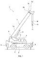
- Fig. 1 is a right side view of a crane 1 according to an embodiment of the present invention.
- This crane 1 includes: a carrier 2 serving as a body portion (body) of a vehicle having a traveling feature; a turning base 3 attached to an upper part of the carrier 2 in a horizontally turnable manner; and an operating room 4 provided at the turning base 3.
- a boom bracket 6 is fixed at an upper side of the turning base 3.
- a boom 7 is attached to this boom bracket 6.
- the boom 7 includes a base end portion attached to the boom bracket 6 via a boom-root supporting pin 8 and is thus capable of being raised and lowered around this boom-root supporting pin 8.
- a derrick cylinder 9 is placed between the boom bracket 6 and the boom 7. Extension and retraction of this derrick cylinder 9 raises or lowers the boom 7.
- the boom 7 includes a base end boom 7a, an intermediate boom 7b, and a leading end boom 7c which are combined together telescopically in the base end boom 7a in this order with the boom 7a, intermediate boom 7b, and leading end boom 7c being at the outermost, intermediate, and innermost positions, respectively.
- the booms 7a to 7c are internally coupled together by telescopic cylinders (not illustrated), and slide for extension or retraction when these telescopic cylinders slide for extension or retraction.
- a leading end 7d of the leading end boom 7c is provided with a sheave (not illustrated).
- a wire rope W extending from a winch (not illustrated) provided at the boom bracket 6 is wound around the sheave.
- a hook block 10 is suspended from the wire rope W.
- a hook 11 is attached to a lower side of the hook block 10. This hook 11 hooks a suspended load (not illustrated) using a crane wire rope (not illustrated).
- An operation unit (not illustrated) is provided inside the operating room 4. This operation unit is provided for an operator to perform operation to turn the turn table 3, to raise or lower and/or extend or retract the boom 7, to wind or unwind the winch, to extend or retract each of the outriggers 5, and to start or stop the engine, for example.
- Fig. 2 is a block diagram illustrating a configuration of a position information management system 21 according to the present invention, which is used for the crane 1.
- This position information management system 21 is a system which transmits, using a remote communication system 25, position information of cranes 1 dispersedly disposed at various locations to a management center 100 at a location distant from the cranes 1 (remote location), and manages the position information of the cranes 1 at the management center 100.
- This position information management system 21 is configured in such a way that a transmission controller 22 serves as a primary component.
- This transmission controller 22 is provided within the operation room 4 of the crane 1 (see Fig. 1 ), for example.
- a GPS sensor 23a and a work-state detector 24 are connected to an input side of the transmission controller 22.
- a crane-side transmitter-receiver 25a of the remote communication system 25 is connected to an output side of the transmission controller 22.
- the GPS sensor 23a, work-state detector 24, and crane-side transmitter-receiver 25a are mounted on the crane 1.
- the GPS sensor 23a is communicably connected to a GPS satellite 23b.
- a positioning system 23 according to the present invention is composed of the GPS sensor 23a and GPS satellite 23b.
- the GPS satellite 23b transmits the position information of the GPS satellite 23b and time information to the GPS sensor 23a.
- the GPS sensor 23a computes the position of the crane 1 based on the position information transmitted from the GPS satellite 23b.
- the work-state detector 24 detects whether the crane 1 is in a work state. Specific examples of the method of detecting whether a crane is in the work state include the following methods (1) to (7).
- the transmission controller 22 determines whether the crane 1 has started work, based on the result of detection by the work-state detector 24. More specifically, the transmission controller 22 determines whether the crane 1 has started work, based on whether the crane 1 has shifted to a work state from a non-work state based on the result of detection by the work-state detector 24.
- the transmission controller 22 When determining that the crane 1 has started work, based on the result of detection by the work-state detector 24, the transmission controller 22 outputs the position information (position information when the work is started) of the crane 1 and time information acquired from the GPS sensor 23a at that time to the remote communication system 25 together with the ID number of the crane 1. The ID number is used to distinguish the crane 1 from another crane 1.
- the remote communication system 25 is a system which performs communication using radio.
- This remote communication system 25 includes: a crane-side transmitter-receiver 25a connected to the transmission controller 22; and a management-center-side transmitter-receiver 25c communicably connected to the crane-side transmitter-receiver 25a via a communication unit 25b.
- the management-center-side transmitter-receiver 25c is disposed at the management center 100.
- the crane-side transmitter-receiver 25a transmits, to the management-center-side transmitter-receiver 25c, the position information of the crane 1 when the crane 1 starts work, the time information and the ID number of the crane 1 outputted from the transmission controller 22.
- a known system such as a satellite communication system or a terrestrial mobile communication system (portable phone, PHS, or wireless LAN), for example, can be cited as the communication unit 25b.
- a data management unit 26 is connected to the management-center-side transmitter-receiver 25c.
- This data management unit 26 includes a database system and saves the position information of the crane 1 when the crane 1 starts work, the time information and the ID number of the crane 1 outputted from the management center-side transmitter-receiver 25c in this database system.
- the data management unit 26 is configured to be capable of outputting these pieces of information saved in the database system, upon request for use.
- the position information management system 21 employs the configuration in which the position information when the crane 1 starts work is transmitted to the data management unit 26 as the position information of the crane 1.
- the same position information does not have to be transmitted many times, and unnecessary position information during moving does not have to be transmitted.
- the data management unit 26 is no longer required to save a large amount of unnecessary data. Accordingly, the position information management system 21 according to the present embodiment can avoid an increase in transmission and data management costs in management of the work positions of the cranes 1.
- the management center-side transmitter-receiver 25c is capable of transmitting the information saved in the data management unit 26 (such as position information of another crane 1) to the crane-side transmitter-receiver 25a in addition to or instead of receiving the information transmitted from the crane-side transmitter-receiver 25a and outputting the received information to the data management unit 26.
- the crane-side transmitter-receiver 25a may receive the information transmitted from the management-center-side transmitter-receiver 25c and display the information on a monitor (not illustrated), for example.
- the position information management system 21 may configure at least one of the management-center-side transmitter-receiver 25c and the crane-side transmitter-receiver 25a to be connectable to the Internet in order for the position information management system 21 to acquire various information from the Internet.
- the position information when work is started is used as the position information of the crane 1 in the position information management system 21 according to the present embodiment, but position information when the crane 1 ends work (starts moving) may be used.
- the management procedure in this case will be described, hereinafter.
- the transmission controller 22 determines whether the crane 1 has ended work, based on the result of detection by the work-state detector 24. More specifically, the transmission controller 22 determines whether the crane 1 has ended work, based on whether the crane 1 has shifted to the non-work state from the work state, based on the result of detection by the work-state detector 24.
- the traveling speed of the crane 1 may be detected to determine whether the crane 1 has ended the work (has started moving), based on a change in traveling speed or a change in traveling distance may be detected using the positioning system 23 to determine whether the crane 1 has ended the work. Moreover, whether the work state of the crane 1 lasts for a predetermined period or an accumulated total period of the work state reaches the predetermined period may be determined to determine whether the crane 1 has ended work.
- the transmission controller 22 transmits the position information of the crane 1 (position information when the crane 1 has ended the work) and the time information acquired from the GPS sensor 23a at that time to the data management unit 26 from the remote communication system 25 together with the ID number.
- the data management unit 26 saves these pieces of information transmitted from the remote communication system 25 and outputs these saved pieces of information upon request for use.
- the received time of the position information when the work is started and the received time of the position information when the work is ended may be measured to compute the difference between the received times (actual work time) to determine whether the actual work time exceeds a previously stored expected work time.
- the data management unit 26 may notify a person at the management center 100 accordingly by displaying a notification message on a monitor, for example.
- the received time of the position information when the work is ended (when traveling is started) and the received time of the position information when work is started next may be measured to compute the difference between the received times (actual moving time) to determine whether the actual moving time exceeds a previously stored expected moving time.
- the data management unit 26 may notify a person at the management center 100 accordingly by displaying a notification message on a monitor, for example.
- the person at the management center 100 can immediately know that an unexpected situation such as a trouble during work or moving has occurred at the crane 1 and promptly take an appropriate measure for the situation.
- the position information management system may use, as the position information of the crane 1, the position information when the work is ended instead of the position information when the work is started.
- ID numbers are managed in addition to the position information of the cranes 1 and the time information, but ID numbers are not necessarily managed as long as the cranes 1 are distinguishable from one another based on information from the remote communication line.
- a satellite positioning system (so called GPS) is used as the positioning system 23, but another positioning system may be used.
- the other positioning system include a positioning system using an electric wave of a mobile communication system such as a portable phone or a laser-tracking positioning system can be cited.
Landscapes
- Engineering & Computer Science (AREA)
- Business, Economics & Management (AREA)
- Physics & Mathematics (AREA)
- General Physics & Mathematics (AREA)
- Human Resources & Organizations (AREA)
- Strategic Management (AREA)
- Economics (AREA)
- Marketing (AREA)
- General Business, Economics & Management (AREA)
- Tourism & Hospitality (AREA)
- Theoretical Computer Science (AREA)
- Entrepreneurship & Innovation (AREA)
- Remote Sensing (AREA)
- Radar, Positioning & Navigation (AREA)
- Mechanical Engineering (AREA)
- Automation & Control Theory (AREA)
- Game Theory and Decision Science (AREA)
- Health & Medical Sciences (AREA)
- Operations Research (AREA)
- Quality & Reliability (AREA)
- Development Economics (AREA)
- Primary Health Care (AREA)
- General Health & Medical Sciences (AREA)
- Educational Administration (AREA)
- Computer Networks & Wireless Communication (AREA)
- General Engineering & Computer Science (AREA)
- Selective Calling Equipment (AREA)
- Jib Cranes (AREA)
- Position Fixing By Use Of Radio Waves (AREA)
- Traffic Control Systems (AREA)
Abstract
Description
- The present invention relates to a position information management system which manages the position information of a machine such as a crane.
- Heretofore, a position information management system for machines as illustrated in Patent Literature (hereinafter, referred to as "PTL") 1, for example, has been proposed for the purpose of knowing the positions of machines such as cranes dispersedly disposed at various locations.
- In the position information management system in
PTL 1, a mobile communication device (transmission controller) transmits, at regular time intervals or regular distances, the position information of a machine, which is acquired from a positioning system such as a GPS, to a management unit (data management unit) at a remote location using a remote communication system. - The data management unit is configured to save the position information of a machine and output the saved position information upon request for use.
- PTL 1: Japanese Patent No.
4921123 - In the position information management system in
PTL 1, however, application of the method of transmitting the position information at regular time intervals in management of work positions (fixed positions) results in transmitting the same position information many times during work. Meanwhile, application of the method of transmitting the position information at regular distances results in transmitting unnecessary position information many times during moving. - Accordingly, performing unnecessary transmission many times involves unnecessary transmission costs. In addition, the data management unit saves a large amount of unnecessary data in association with the transmission, so that this operation of the data management unit involves unnecessary data management costs.
- The present invention has been made in consideration of the problems mentioned above and thus aims to provide a position information management system for a machine (hereinafter, referred to as "machine-position-information management system") capable of reducing the transmission and data management costs in management of the work positions of machines.
- As a result of careful study, the present inventor et al. have employed the following machine-position-information management system in order to solve the problems mentioned above.
- A machine-position-information management system according to the present invention includes a transmission controller configured to transmit position information of a machine to a data management unit at a remote location using a remote communication system, the position information being acquired from a positioning system, and the data management unit being configured to save the position information and to output the saved position information upon request for use, the machine-position-information management system further comprising a work-state detector configured to detect whether the machine is in a work state, in which: the transmission controller determines whether the machine has started work, based on a result of the detection by the work-state detector, and when determining that the machine has started work, the transmission controller outputs the position information acquired from the positioning system at this time to the remote communication system.
- In the machine-position-information management system according to the present invention, the transmission controller may determine whether the machine has ended work, based on a result of the detection by the work-state detector, and when determining that the machine has ended work, the transmission controller may output the position information acquired from the positioning system at this time to the remote communication system.
- In a machine-position-information management system according to the present invention, position information when work is started is transmitted to a data management unit as the position information of the machine. For this reason, unlike the related art, the same position information does not have to be transmitted many times and unnecessary position information does not have to be transmitted during moving in management of work positions. Furthermore, the data management unit is no longer required to save a large amount of data with this configuration. Accordingly, the machine-position-information management system according to the present invention can avoid an increase in transmission and data management costs in management of the work positions of machines.
-
-
Fig. 1 is right side view of a crane according to an embodiment of the present invention. -
Fig. 2 is a block diagram illustrating a configuration of a position information management system according to the embodiment. - Hereinafter, an embodiment of the present invention will be described with reference to the drawings.
-
Fig. 1 is a right side view of acrane 1 according to an embodiment of the present invention. The overall configuration of thecrane 1 will be described first. Thiscrane 1 includes: acarrier 2 serving as a body portion (body) of a vehicle having a traveling feature; aturning base 3 attached to an upper part of thecarrier 2 in a horizontally turnable manner; and anoperating room 4 provided at theturning base 3. - Left and right pairs of
outriggers 5 are provided at the front and rear sides of thecarrier 2, respectively (only outriggers on the right side are illustrated). Aboom bracket 6 is fixed at an upper side of theturning base 3. Aboom 7 is attached to thisboom bracket 6. - The
boom 7 includes a base end portion attached to theboom bracket 6 via a boom-root supporting pin 8 and is thus capable of being raised and lowered around this boom-root supporting pin 8. Aderrick cylinder 9 is placed between theboom bracket 6 and theboom 7. Extension and retraction of thisderrick cylinder 9 raises or lowers theboom 7. - The
boom 7 includes abase end boom 7a, anintermediate boom 7b, and a leadingend boom 7c which are combined together telescopically in thebase end boom 7a in this order with theboom 7a,intermediate boom 7b, and leadingend boom 7c being at the outermost, intermediate, and innermost positions, respectively. Thebooms 7a to 7c are internally coupled together by telescopic cylinders (not illustrated), and slide for extension or retraction when these telescopic cylinders slide for extension or retraction. - A leading
end 7d of the leadingend boom 7c is provided with a sheave (not illustrated). A wire rope W extending from a winch (not illustrated) provided at theboom bracket 6 is wound around the sheave. Ahook block 10 is suspended from the wire ropeW. A hook 11 is attached to a lower side of thehook block 10. Thishook 11 hooks a suspended load (not illustrated) using a crane wire rope (not illustrated). - An operation unit (not illustrated) is provided inside the
operating room 4. This operation unit is provided for an operator to perform operation to turn the turn table 3, to raise or lower and/or extend or retract theboom 7, to wind or unwind the winch, to extend or retract each of theoutriggers 5, and to start or stop the engine, for example. -
Fig. 2 is a block diagram illustrating a configuration of a positioninformation management system 21 according to the present invention, which is used for thecrane 1. This positioninformation management system 21 is a system which transmits, using aremote communication system 25, position information ofcranes 1 dispersedly disposed at various locations to amanagement center 100 at a location distant from the cranes 1 (remote location), and manages the position information of thecranes 1 at themanagement center 100. - This position
information management system 21 is configured in such a way that atransmission controller 22 serves as a primary component. Thistransmission controller 22 is provided within theoperation room 4 of the crane 1 (seeFig. 1 ), for example. - A
GPS sensor 23a and a work-state detector 24 are connected to an input side of thetransmission controller 22. A crane-side transmitter-receiver 25a of theremote communication system 25 is connected to an output side of thetransmission controller 22. TheGPS sensor 23a, work-state detector 24, and crane-side transmitter-receiver 25a are mounted on thecrane 1. - The
GPS sensor 23a is communicably connected to aGPS satellite 23b. In this embodiment, apositioning system 23 according to the present invention is composed of theGPS sensor 23a andGPS satellite 23b. TheGPS satellite 23b transmits the position information of theGPS satellite 23b and time information to theGPS sensor 23a. TheGPS sensor 23a computes the position of thecrane 1 based on the position information transmitted from theGPS satellite 23b. - The work-
state detector 24 detects whether thecrane 1 is in a work state. Specific examples of the method of detecting whether a crane is in the work state include the following methods (1) to (7). -
- (1) Detecting whether all the
outriggers 5 are on the ground. - (2) Detecting whether the operation to place an
outrigger 5 on the ground has been selected with the operation unit. - (3) Detecting whether the
boom 7 has left from a predetermined retracted position. - (4) Detecting whether a parking brake has been activated.
- (5) Detecting whether an actuator (such as a cylinder or motor) has been activated.
- (6) Detecting whether a PTO has been turned ON.
- (7) Detecting whether the power supply of a work controller has been turned ON.
- The
transmission controller 22 determines whether thecrane 1 has started work, based on the result of detection by the work-state detector 24. More specifically, thetransmission controller 22 determines whether thecrane 1 has started work, based on whether thecrane 1 has shifted to a work state from a non-work state based on the result of detection by the work-state detector 24. - When determining that the
crane 1 has started work, based on the result of detection by the work-state detector 24, thetransmission controller 22 outputs the position information (position information when the work is started) of thecrane 1 and time information acquired from theGPS sensor 23a at that time to theremote communication system 25 together with the ID number of thecrane 1. The ID number is used to distinguish thecrane 1 from anothercrane 1. - The
remote communication system 25 is a system which performs communication using radio. Thisremote communication system 25 includes: a crane-side transmitter-receiver 25a connected to thetransmission controller 22; and a management-center-side transmitter-receiver 25c communicably connected to the crane-side transmitter-receiver 25a via acommunication unit 25b. The management-center-side transmitter-receiver 25c is disposed at themanagement center 100. - The crane-side transmitter-
receiver 25a transmits, to the management-center-side transmitter-receiver 25c, the position information of thecrane 1 when thecrane 1 starts work, the time information and the ID number of thecrane 1 outputted from thetransmission controller 22. - Note that, a known system such as a satellite communication system or a terrestrial mobile communication system (portable phone, PHS, or wireless LAN), for example, can be cited as the
communication unit 25b. - In the
management center 100, adata management unit 26 is connected to the management-center-side transmitter-receiver 25c. Thisdata management unit 26 includes a database system and saves the position information of thecrane 1 when thecrane 1 starts work, the time information and the ID number of thecrane 1 outputted from the management center-side transmitter-receiver 25c in this database system. In addition, thedata management unit 26 is configured to be capable of outputting these pieces of information saved in the database system, upon request for use. - As described above, the position
information management system 21 according to the present embodiment employs the configuration in which the position information when thecrane 1 starts work is transmitted to thedata management unit 26 as the position information of thecrane 1. Thus, unlike the related art, the same position information does not have to be transmitted many times, and unnecessary position information during moving does not have to be transmitted. Furthermore, because of this configuration, thedata management unit 26 is no longer required to save a large amount of unnecessary data. Accordingly, the positioninformation management system 21 according to the present embodiment can avoid an increase in transmission and data management costs in management of the work positions of thecranes 1. - Moreover, the management center-side transmitter-
receiver 25c is capable of transmitting the information saved in the data management unit 26 (such as position information of another crane 1) to the crane-side transmitter-receiver 25a in addition to or instead of receiving the information transmitted from the crane-side transmitter-receiver 25a and outputting the received information to thedata management unit 26. In this case, the crane-side transmitter-receiver 25a may receive the information transmitted from the management-center-side transmitter-receiver 25c and display the information on a monitor (not illustrated), for example. - Furthermore, the position
information management system 21 may configure at least one of the management-center-side transmitter-receiver 25c and the crane-side transmitter-receiver 25a to be connectable to the Internet in order for the positioninformation management system 21 to acquire various information from the Internet. - The embodiment according to the present invention has been described thus far, but this embodiment is not intended to limit the contents of the present invention. In addition, various modifications are possible within a range not departing from the claims of the present invention.
- For example, the position information when work is started is used as the position information of the
crane 1 in the positioninformation management system 21 according to the present embodiment, but position information when thecrane 1 ends work (starts moving) may be used. The management procedure in this case will be described, hereinafter. - The
transmission controller 22 determines whether thecrane 1 has ended work, based on the result of detection by the work-state detector 24. More specifically, thetransmission controller 22 determines whether thecrane 1 has ended work, based on whether thecrane 1 has shifted to the non-work state from the work state, based on the result of detection by the work-state detector 24. - Moreover, the traveling speed of the
crane 1 may be detected to determine whether thecrane 1 has ended the work (has started moving), based on a change in traveling speed or a change in traveling distance may be detected using thepositioning system 23 to determine whether thecrane 1 has ended the work. Moreover, whether the work state of thecrane 1 lasts for a predetermined period or an accumulated total period of the work state reaches the predetermined period may be determined to determine whether thecrane 1 has ended work. - When determining that the
crane 1 has ended work, based on the result of detection by the work-state detector 24, thetransmission controller 22 transmits the position information of the crane 1 (position information when thecrane 1 has ended the work) and the time information acquired from theGPS sensor 23a at that time to thedata management unit 26 from theremote communication system 25 together with the ID number. Thedata management unit 26 saves these pieces of information transmitted from theremote communication system 25 and outputs these saved pieces of information upon request for use. - Saving the position information when the
crane 1 has ended work as the position information of thecrane 1 in the manner described above enhances the accuracy of position information and allows the user to surely know the work position of thecrane 1. - Moreover, in the
data management section 26, the received time of the position information when the work is started and the received time of the position information when the work is ended may be measured to compute the difference between the received times (actual work time) to determine whether the actual work time exceeds a previously stored expected work time. Moreover, when the actual work time has exceeded the expected work time, thedata management unit 26 may notify a person at themanagement center 100 accordingly by displaying a notification message on a monitor, for example. - Furthermore, in the
data management section 26, the received time of the position information when the work is ended (when traveling is started) and the received time of the position information when work is started next may be measured to compute the difference between the received times (actual moving time) to determine whether the actual moving time exceeds a previously stored expected moving time. Moreover, when the actual moving time has exceeded the expected moving time, thedata management unit 26 may notify a person at themanagement center 100 accordingly by displaying a notification message on a monitor, for example. - Accordingly, the person at the
management center 100 can immediately know that an unexpected situation such as a trouble during work or moving has occurred at thecrane 1 and promptly take an appropriate measure for the situation. Note that, the position information management system may use, as the position information of thecrane 1, the position information when the work is ended instead of the position information when the work is started. - Moreover, in the position
information management system 21 according to the present embodiment, ID numbers are managed in addition to the position information of thecranes 1 and the time information, but ID numbers are not necessarily managed as long as thecranes 1 are distinguishable from one another based on information from the remote communication line. - Furthermore, in the position
information management system 21 according to the present embodiment, a satellite positioning system (so called GPS) is used as thepositioning system 23, but another positioning system may be used. Examples of the other positioning system include a positioning system using an electric wave of a mobile communication system such as a portable phone or a laser-tracking positioning system can be cited. - Furthermore, in the position
information management system 21 according to the present embodiment, application to thecrane 1 has been described, but application to another machine (such as a machine used at a high position) may be possible. - This application claims and is entitled to the benefit of Japanese Patent Application No.
2013-209595, filed on October 4, 2013 -
- 1
- Crane (machine vehicle)
- 21
- Position information management system
- 22
- Transmission control section
- 23
- Positioning system
- 24
- Work-state detector
- 25
- Remote communication system
- 26
- Data management unit
Claims (2)
- A machine-position-information management system comprising a transmission controller configured to transmit position information of a machine to a data management unit at a remote location using a remote communication system, the position information being acquired from a positioning system, and the data management unit being configured to save the position information and to output the saved position information upon request for use,
the machine-position-information management system further comprising a work-state detector configured to detect whether the machine is in a work state, wherein:the transmission controller determines whether the machine has started work, based on a result of the detection by the work-state detector, andwhen determining that the machine has started work, the transmission controller outputs the position information acquired from the positioning system at this time to the remote communication system. - The machine-position-information management system according to claim 1, wherein:the transmission controller determines whether the machine has ended work, based on a result of the detection by the work-state detector, andwhen determining that the machine has ended work, the transmission controller outputs the position information acquired from the positioning system at this time to the remote communication system.
Applications Claiming Priority (2)
| Application Number | Priority Date | Filing Date | Title |
|---|---|---|---|
| JP2013209595A JP2015075790A (en) | 2013-10-04 | 2013-10-04 | Work machine position information management system |
| PCT/JP2014/069537 WO2015049911A1 (en) | 2013-10-04 | 2014-07-24 | Work machine position information management system |
Publications (2)
| Publication Number | Publication Date |
|---|---|
| EP3054411A1 true EP3054411A1 (en) | 2016-08-10 |
| EP3054411A4 EP3054411A4 (en) | 2017-03-01 |
Family
ID=52778508
Family Applications (1)
| Application Number | Title | Priority Date | Filing Date |
|---|---|---|---|
| EP14850214.9A Withdrawn EP3054411A4 (en) | 2013-10-04 | 2014-07-24 | Work machine position information management system |
Country Status (5)
| Country | Link |
|---|---|
| US (1) | US20160225199A1 (en) |
| EP (1) | EP3054411A4 (en) |
| JP (1) | JP2015075790A (en) |
| CN (1) | CN105593893A (en) |
| WO (1) | WO2015049911A1 (en) |
Cited By (1)
| Publication number | Priority date | Publication date | Assignee | Title |
|---|---|---|---|---|
| EP4174014A1 (en) * | 2021-11-02 | 2023-05-03 | Hiab AB | A loader crane system |
Families Citing this family (4)
| Publication number | Priority date | Publication date | Assignee | Title |
|---|---|---|---|---|
| EP3617129B1 (en) * | 2017-04-27 | 2024-02-14 | Tadano Ltd. | Remote operation terminal and system for preventing remote operation terminal from being mislaid |
| DE102018005068A1 (en) * | 2018-06-26 | 2020-01-02 | Liebherr-Components Biberach Gmbh | Crane and method for controlling such a crane |
| CN111369780B (en) * | 2018-12-26 | 2021-09-03 | 北京图森智途科技有限公司 | Accurate parking method, equipment and system for truck in shore crane area |
| CN111634868B (en) * | 2020-07-02 | 2025-02-11 | 上海华兴数字科技有限公司 | Electric drive aerial work vehicle control system and aerial work management system |
Family Cites Families (9)
| Publication number | Priority date | Publication date | Assignee | Title |
|---|---|---|---|---|
| WO2000052627A1 (en) * | 1999-03-01 | 2000-09-08 | North Carolina State University | Crane monitoring and data retrieval system and method |
| US6728619B2 (en) * | 2000-03-31 | 2004-04-27 | Hitachi Construction Machinery Co., Ltd. | Failure measure outputting method, output system, and output device |
| US7734399B2 (en) * | 2006-02-10 | 2010-06-08 | American Lafrance, Llc | Outrigger obstruction detection system for aerial fire trucks |
| JP4921123B2 (en) | 2006-11-13 | 2012-04-25 | 株式会社小松製作所 | MOBILE COMMUNICATION DEVICE, MOBILE COMMUNICATION DEVICE CONTROL METHOD, AND MOBILE MONITORING SYSTEM |
| US8224518B2 (en) * | 2008-08-18 | 2012-07-17 | Trimble Navigation Limited | Automated recordation of crane inspection activity |
| ES2361363B1 (en) * | 2011-02-04 | 2012-01-03 | RICARDO ROMERO MARTI (Titular al 40%) | SMART SYSTEM FOR THE CONTROL AND MANAGEMENT OF A MOTOR VEHICLE FOR THE COLLECTION OF WASTE CONTAINERS. |
| RU2012140237A (en) * | 2011-09-23 | 2014-03-27 | МАНИТОВОК КРЕЙН КАМПЕНИЗ, ЭлЭлСи | SYSTEM AND METHODS FOR MONITORING OUTDOOR SUPPORTS |
| JP2013117854A (en) * | 2011-12-02 | 2013-06-13 | Yanmar Co Ltd | Management server of remote monitoring system |
| US8738175B2 (en) * | 2011-12-13 | 2014-05-27 | Trimble Navigation Limited | RFID for location of the load on a tower crane |
-
2013
- 2013-10-04 JP JP2013209595A patent/JP2015075790A/en active Pending
-
2014
- 2014-07-24 EP EP14850214.9A patent/EP3054411A4/en not_active Withdrawn
- 2014-07-24 WO PCT/JP2014/069537 patent/WO2015049911A1/en not_active Ceased
- 2014-07-24 US US15/024,893 patent/US20160225199A1/en not_active Abandoned
- 2014-07-24 CN CN201480053492.9A patent/CN105593893A/en active Pending
Cited By (1)
| Publication number | Priority date | Publication date | Assignee | Title |
|---|---|---|---|---|
| EP4174014A1 (en) * | 2021-11-02 | 2023-05-03 | Hiab AB | A loader crane system |
Also Published As
| Publication number | Publication date |
|---|---|
| WO2015049911A1 (en) | 2015-04-09 |
| EP3054411A4 (en) | 2017-03-01 |
| JP2015075790A (en) | 2015-04-20 |
| US20160225199A1 (en) | 2016-08-04 |
| CN105593893A (en) | 2016-05-18 |
Similar Documents
| Publication | Publication Date | Title |
|---|---|---|
| US20160225199A1 (en) | Machine-position-information management system, crane, and data management apparatus | |
| US8777027B2 (en) | Mobile crane | |
| CN105143088B (en) | remote controlled crane | |
| US8950605B2 (en) | Monitoring and alarm device for construction machinery | |
| US9783397B2 (en) | Work state monitoring device for work vehicle | |
| CN103640980B (en) | Tower crane safety control method, device, system and tower crane | |
| JP2011102167A (en) | Hanging load position monitoring system for crane, and hanging tool | |
| US20150314997A1 (en) | Cable breakage diagnosis in a crane | |
| KR101103719B1 (en) | Tower crane unloading position target device | |
| CN202279092U (en) | Construction machinery capable of detecting outrigger extension | |
| CN204416973U (en) | Suspension arm of crane protection against electric shock prior-warning device | |
| CN202429931U (en) | Retraction-in-position detection device for crane and its outriggers | |
| EP3594165A1 (en) | Crane | |
| ES3013246T3 (en) | Arm with two or more hooks | |
| US20070084813A1 (en) | Support device for a mobile crane | |
| CN200992464Y (en) | Lifting mechanical apparatus with position safety monitoring system | |
| US11952244B2 (en) | Crane and method for determining weight state in crane | |
| CN102424037A (en) | Operation control method for construction machinery and its outriggers | |
| JP2014181120A (en) | Work vehicle | |
| JP2018167982A (en) | crane | |
| KR200438972Y1 (en) | Crane safety device | |
| US3771668A (en) | Tension scale system for lifting cable of a telescoping boom crane | |
| RU2810831C2 (en) | Improved boom with two or more hooks | |
| KR200363683Y1 (en) | Apparatus wirelessly regulating the hoisting limit of cargo-crane | |
| JP2004018220A (en) | Safety device for work machine |
Legal Events
| Date | Code | Title | Description |
|---|---|---|---|
| PUAI | Public reference made under article 153(3) epc to a published international application that has entered the european phase |
Free format text: ORIGINAL CODE: 0009012 |
|
| 17P | Request for examination filed |
Effective date: 20160331 |
|
| AK | Designated contracting states |
Kind code of ref document: A1 Designated state(s): AL AT BE BG CH CY CZ DE DK EE ES FI FR GB GR HR HU IE IS IT LI LT LU LV MC MK MT NL NO PL PT RO RS SE SI SK SM TR |
|
| AX | Request for extension of the european patent |
Extension state: BA ME |
|
| DAX | Request for extension of the european patent (deleted) | ||
| A4 | Supplementary search report drawn up and despatched |
Effective date: 20170126 |
|
| RIC1 | Information provided on ipc code assigned before grant |
Ipc: G08G 1/123 20060101ALI20170120BHEP Ipc: B66C 13/16 20060101ALI20170120BHEP Ipc: G06Q 10/06 20120101ALI20170120BHEP Ipc: G05B 15/02 20060101ALI20170120BHEP Ipc: G01S 19/13 20100101ALI20170120BHEP Ipc: G07C 5/00 20060101ALI20170120BHEP Ipc: G08G 1/13 20060101ALI20170120BHEP Ipc: G06Q 50/08 20120101AFI20170120BHEP |
|
| 17Q | First examination report despatched |
Effective date: 20180716 |
|
| STAA | Information on the status of an ep patent application or granted ep patent |
Free format text: STATUS: THE APPLICATION IS DEEMED TO BE WITHDRAWN |
|
| 18D | Application deemed to be withdrawn |
Effective date: 20181127 |