EP3054290A1 - Ion-selective electrode - Google Patents
Ion-selective electrode Download PDFInfo
- Publication number
- EP3054290A1 EP3054290A1 EP14849328.1A EP14849328A EP3054290A1 EP 3054290 A1 EP3054290 A1 EP 3054290A1 EP 14849328 A EP14849328 A EP 14849328A EP 3054290 A1 EP3054290 A1 EP 3054290A1
- Authority
- EP
- European Patent Office
- Prior art keywords
- ion
- electrode
- graphite
- mixture
- sensitive membrane
- Prior art date
- Legal status (The legal status is an assumption and is not a legal conclusion. Google has not performed a legal analysis and makes no representation as to the accuracy of the status listed.)
- Granted
Links
Images







Classifications
-
- G—PHYSICS
- G01—MEASURING; TESTING
- G01N—INVESTIGATING OR ANALYSING MATERIALS BY DETERMINING THEIR CHEMICAL OR PHYSICAL PROPERTIES
- G01N27/00—Investigating or analysing materials by the use of electric, electrochemical, or magnetic means
- G01N27/26—Investigating or analysing materials by the use of electric, electrochemical, or magnetic means by investigating electrochemical variables; by using electrolysis or electrophoresis
- G01N27/28—Electrolytic cell components
- G01N27/30—Electrodes, e.g. test electrodes; Half-cells
- G01N27/333—Ion-selective electrodes or membranes
- G01N27/3335—Ion-selective electrodes or membranes the membrane containing at least one organic component
-
- G—PHYSICS
- G01—MEASURING; TESTING
- G01N—INVESTIGATING OR ANALYSING MATERIALS BY DETERMINING THEIR CHEMICAL OR PHYSICAL PROPERTIES
- G01N27/00—Investigating or analysing materials by the use of electric, electrochemical, or magnetic means
- G01N27/26—Investigating or analysing materials by the use of electric, electrochemical, or magnetic means by investigating electrochemical variables; by using electrolysis or electrophoresis
- G01N27/28—Electrolytic cell components
- G01N27/30—Electrodes, e.g. test electrodes; Half-cells
- G01N27/308—Electrodes, e.g. test electrodes; Half-cells at least partially made of carbon
-
- G—PHYSICS
- G01—MEASURING; TESTING
- G01N—INVESTIGATING OR ANALYSING MATERIALS BY DETERMINING THEIR CHEMICAL OR PHYSICAL PROPERTIES
- G01N27/00—Investigating or analysing materials by the use of electric, electrochemical, or magnetic means
- G01N27/26—Investigating or analysing materials by the use of electric, electrochemical, or magnetic means by investigating electrochemical variables; by using electrolysis or electrophoresis
- G01N27/28—Electrolytic cell components
- G01N27/30—Electrodes, e.g. test electrodes; Half-cells
- G01N27/333—Ion-selective electrodes or membranes
Definitions
- the present invention relates to an ion selective electrode used for measuring an electrolyte concentration in a solution.
- ISE ion selective electrode
- a sample solution together with a reference electrode to measure a potential difference between the two electrodes and thus determine ions, which are measurement targets, in the sample. Due to the simplicity, the ISE is widely used in the field of analysis. In the field of medicine, the ISE is used for clinical laboratory tests and is used to measure an electrolyte not only with a dedicated device for measuring electrolytes but also with a biochemical automatic analysis device, an urgent sample testing device, or a point-of-care testing device.
- the ISE uses an ion-sensitive membrane to selectively measure ions, which are the measurement targets, from a plurality of ions.
- An ion-sensitive membrane that is typically used is a membrane obtained by mixing a plasticizer and a ligand into a polymer-based substance such as polyvinyl chloride, and by further mixing a salt thereinto depending on cases.
- the ion-sensitive membrane generates a potential based on the Nernst equation in accordance with the concentration of ions that are the measurement targets.
- an internal-liquid-type ISE Such an electrode with a structure in which a side of a sensitive membrane that is on the opposite side of a sample solution is filled with an aqueous solution or gel is called an internal-liquid-type ISE.
- an electrode with a structure in which a surface of a sensitive membrane on the opposite side of a sample solution is allowed to be in direct contact with a conductive electrode is called a coated wire-ion selective electrode (CW-ISE) or a solid contact-ion selective electrode (SC-ISE).
- CW-ISE coated wire-ion selective electrode
- SC-ISE solid contact-ion selective electrode
- solid electrodes Since solid electrodes do not require an internal solution, such electrodes can be easily reduced in size and have been applied to point-of-care testing devices.
- an electrode for an electrode (base electrode) that is allowed to be in contact with a sensitive membrane, platinum, silver chloride covered with a conductive polymer, gold modified with a monomolecular film, porous carbon, carbon black, or a mixture of a polymer and graphite has been used.
- Patent Literature 1 JP 2007-534949A ( WO 2005/103664 )
- the inventors have conducted research and development to devise a solid-electrode-type ISE with high potential stability and small individual variations. As a consequence, it has been found to be impossible to obtain both sufficient potential stability and small individual variations with the conventional methods.
- ions that control a potential between a base electrode and a sensitive membrane and ions that control a potential between the sensitive membrane and a sample solution are different or unknown.
- a potential between the sensitive membrane and the base electrode is controlled by the transfer of electrons that occurs in redox reactions, while a potential between the sensitive membrane and the sample solution is controlled by the ions that are the measurement targets, for example, potassium ions.
- the ISE in accordance with the present invention includes a mixture of graphite and liquid oil as a base electrode.
- the ISE in accordance with the present invention is an electrode for selectively detecting an ion as a measurement target in a measurement solution, and includes an ion-sensitive membrane adapted to be in contact with the measurement solution, a mixture of graphite and liquid oil, the mixture being in contact with the ion-sensitive membrane, and a conductor in contact with the mixture of graphite and liquid oil.
- the ion-sensitive membrane includes a plasticizer and the liquid oil includes the same plasticizer.
- a relative difference between a weight ratio of the plasticizer included in the ion-sensitive membrane and a weight ratio of the plasticizer included in the mixture of graphite and liquid oil is 30% or less.
- the ion-sensitive membrane includes a hydrophobic anion
- the mixture of graphite and liquid oil includes the same hydrophobic anion
- the ion-sensitive membrane includes a substance that selectively binds to the ion as the measurement target, and the mixture of graphite and liquid oil includes the same substance.
- the liquid oil is a fluorine-based polymer or a fluorine-based oil.
- the graphite is synthetic graphite.
- the base electrode responds to monovalent cations, such as lithium, potassium, and sodium, which are the measurement target ions.
- monovalent cations such as lithium, potassium, and sodium
- the base electrode When synthetic graphite is used as the graphite, the base electrode will include no carbon, which has various functional groups on its surface, of the natural graphite. As a consequence, side reactions due to such carbon can be suppressed and the potential stability can thus be obtained.
- Fig. 1 shows schematic diagrams illustrating an example of a solid-electrode-type ISE.
- a flow channel 102 passes through a cartridge 101 of the ISE.
- Fig. 1 (a) illustrates a plane perpendicular to the flow channel
- Fig. 1(b) illustrates a plane parallel with the flow channel.
- Fig. 1(c) illustrates a cross-section along a chain line in Fig. 1(a) , in which a sensitive membrane 105 is in contact with the flow channel, the opposite side of the flow channel is filled with a mixture 104 of graphite and liquid oil, and a platinum wire 103 is in contact with the mixture 104.
- the platinum wire 103 also functions as a terminal.
- the sensitive membrane 105 an ion-selective membrane made of lithium, sodium, or potassium described in Pure Appl. Chem., Vol. 72, No. 10, pp. 1851-2082, 2000 .
- the sensitive membrane 105 is attached to the cartridge 101 made of resin such as polyvinyl chloride, polystyrene, or polypropylene.
- a solvent such as tetrahydrofuran may be used for the attachment.
- mechanical pressure may be applied for the attachment.
- the mixture 104 of graphite and liquid oil is arranged on the sensitive membrane 105.
- graphite and liquid oil are mixed at a weight ratio of 1:2, and are further stirred sufficiently with a mortar.
- a cover 106 is put, and the platinum wire 103 is inserted from a hole in the cover 106 so as to contact the mixture 104 of graphite and liquid oil, thereby realizing electric connection therebetween.
- the liquid oil is preferably in a liquid state at 0°C to 50°C that are the assumed usage environment. This is because if the liquid oil is in a liquid state, the response to monovalent cations, which will be described later, is expected, the adhesion to the sensitive membrane can be maintained, and the movement, if any, of ions in the liquid can be increased in speed, thereby improving the responsiveness. If the liquid oil is a liquid under the usage conditions, the liquid oil need not be liquid over the entire temperature range.
- a substance that is not miscible with water for example, alkane such as paraffin, plasticizer such as DOA, DOP, DOS, or oNPOE described in Pure Appl. Chem., Vol. 72, No. 10, pp. 1851-2082, 2000 , a fluorine-based polymer, or fluorine-based oil.
- FIG. 2 shows schematic diagrams illustrating an example of an internal-liquid-type ISE used for comparison purposes.
- a flow channel 202 passes through a cartridge 201 of the ISE.
- Fig. 2(a) illustrates a plane perpendicular to the flow channel
- Fig. 2(b) illustrates a plane parallel with the flow channel.
- Fig. 2(c) illustrates a cross-section along a chain line in Fig. 2(a) .
- a sensitive membrane 205 is in contact with the flow channel, and the opposite side of the flow channel is filled with an internal solution 204.
- a silver-silver chloride electrode 203 is in contact with the internal solution 204. The silver-silver chloride electrode 203 also functions as a terminal.
- a cation selective electrode made of sodium, potassium, calcium, magnesium, or the like it is possible to use a membrane described in Pure Appl. Chem., Vol. 72, No. 10, pp. 1851-2082, 2000 , for example, as the sensitive membrane 205.
- an anion selective electrode made of chlorine, carbonic acid, thiocyanogen, nitric acid, hydroxyl, phosphate, sulfuric acid, iodine, or the like it is possible to use a membrane described in Pure Appl. Chem., Vol. 74, No. 6, pp.
- Fig. 3 is a schematic diagram illustrating an example of an electrolyte measuring device that uses the ISE in Figs. 1 or Figs. 2 .
- a control unit 302, an operation recording unit 303, and an output unit 304 are connected to a measuring unit 301.
- the measuring unit 301 includes a dilution tank 311, a sample dispensing nozzle 312, a diluent dispensing nozzle 313, an internal-standard-solution dispensing nozzle 314, a suction nozzle 315, a pipe 316, a sodium ISE 317, a potassium ISE 318, a chlorine ISE 319, a reference electrode 320, a pipe 321, a pump 322, and a potential measuring unit 323.
- the sample dispensing nozzle 312, the diluent dispensing nozzle 313, and the internal-standard-solution dispensing nozzle 314 dispense and discharge, to the dilution tank 311, a sample such as blood or urine, a diluent, and an internal-standard-solution, respectively.
- the diluent does not contain the measurement target ions or has a known, low concentration, and can be used for diluting the sample.
- the internal-standard-solution is a sample with a known ion concentration, and can be used for calibrating potentials.
- the sample solution suction nozzle 315 can be moved up and down, and a solution in the dilution tank 311 is sucked with the drive force of the pump 322. The sucked solution is introduced into flow channels of the electrodes 317 to 320 via the pipe 316, and is further discharged via the pipe 321.
- the terminal of each electrode is connected to the potential measuring unit 323.
- Fig. 4 is a schematic diagram illustrating another example of the electrolyte measuring device that uses the ISE in Figs. 1 or Figs. 2 .
- a control unit 402, an operation recording unit 403, and an output unit 404 are connected to a measuring unit 401.
- the measuring unit 401 includes a dilution tank 411, a sample dispensing nozzle 412, a diluent dispensing nozzle 413, an internal-standard-solution dispensing nozzle 414, a suction nozzle 415, a pipe 416, a chlorine ISE 417, a potassium ISE 418, a sodium ISE 419, a pipe 420, a valve 421, a junction 422, a pipe 423, a reference electrode 424, a valve 425, a pipe 426, a reference solution 427, a pipe 428, a pump 429, and a potential measuring unit 430.
- the sample dispensing nozzle 412, the diluent dispensing nozzle 413, and the internal-standard-solution dispensing nozzle 414 dispense and discharge, to the dilution tank 411, a sample such as blood or urine, a diluent, and an internal-standard-solution, respectively.
- the sample solution suction nozzle 415 can be moved up and down, and sucks a solution in the dilution tank 411 with the drive force of the pump 429.
- the sucked solution is introduced into flow channels of the electrodes 417 to 419 via the pipe 416, and is further discharged via the pipe 420, the junction 422, and the pipe 428.
- the pump 429 is driven with the valve 421 closed and the valve 425 open, the reference solution 427 is sucked via the pipe 426 and is introduced into a flow channel of the reference electrode 424. Further, the reference solution 427 is discharged via the pipe 423, the junction 422, and the pipe 428. Terminals of the electrode 417 to 419 and 424 are connected to the potential measuring unit 430.
- the potential measuring unit 430 a potential measuring unit similar to that in Fig. 3 can be used.
- a reference electrode which is formed using porous glass or ceramics described with reference to Fig. 2
- an ISE for the reference electrode 424, and set the electrolyte concentration in the corresponding reference solution 427 constant.
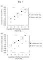
- Fig. 5 illustrates examples of results of measuring the electrolyte concentration using the solid-electrode-type ISE in accordance with the present invention and the conventional internal-liquid-type ISE.
- a potassium ion-selective membrane contains 30%w/w polyvinyl chloride (PVC) as a base substance, 66%w/w oNPOE as a plasticizer, a Bis(benzo-15-crown-5) as a ligand (substance that selectively binds to an ion as a measurement target), and tetraphenyl borate potassium (KTpClPB), which is a salt of a hydrophobic anion excluder, as an anion excluder.
- PVC polyvinyl chloride
- oNPOE 66%w/w oNPOE
- Bis(benzo-15-crown-5) as a ligand (substance that selectively binds to an ion as a measurement target)
- KTpClPB tetrapheny
- a sodium ion-selective membrane contains 30%w/w polyvinyl chloride (PVC) as a base substance, 66%w/w oNPOE as a plasticizer, Bis(12-crown-4) as a ligand (substance that selectively binds to an ion as a measurement target), and a Tetrakis[3,5-bis(trifluorinemethyl)phenyl]borate, sodium salt (NaTFPB), which is a salt of a hydrophobic anion as an anion excluder.
- PVC polyvinyl chloride
- oNPOE plasticizer
- Bis(12-crown-4) as a ligand (substance that selectively binds to an ion as a measurement target)
- NaTFPB Tetrakis[3,5-bis(trifluorinemethyl)phenyl]borate, sodium salt
- Fig. 5(a) illustrates a result of measuring a potassium chloride aqueous solution by using the potassium ISE for the sensitive membrane.
- Fig. 5(b) illustrates a result of measuring a sodium chloride aqueous solution by using the sodium ISE for the sensitive membrane. Both the results are found to exhibit 61.6 mV/decade that is identical to the theoretical value.
- the solid-electrode-type ISE in accordance with the present invention can obtain the same potential response as that of an internal-liquid-type ISE.
- Fig. 6 illustrates measurement results that show that a mixture of graphite and liquid oil has responsiveness to monovalent cations.
- a potentiostat and using a mixture of graphite and liquid oil (without a sensitive membrane) as a working electrode; a silver-silver chloride reference electrode, which uses saturated potassium chloride as an internal solution, as a reference electrode; and a platinum electrode, as a counter electrode, measurement was conducted in a 100 mmol/l lithium chloride aqueous solution ( Fig. 6(a) ), a 100 mmol/l sodium chloride aqueous solution ( Fig. 6(b) ), and a 100 mmol/l potassium chloride aqueous solution ( Fig. 6(c) ).
- the sweep rate was set to 100 mV/s.
- current peaks were observed at around -0.5 V and 0 V under any one of the conditions in Figs. 6(a) to 6(c) . Such peaks are considered to be due to the uptake and release of cations into/from the mixture of graphite and liquid oil.
- a mixture of graphite and liquid oil has responsiveness to monovalent cations, and has low responsiveness to divalent cations.
- Fig. 8 illustrates an example of changes per day of the electromotive force to a similarly produced solid-electrode-type potassium ISE, which uses a mixture of natural graphite and paraffin oil as a base electrode, against a 100 mmol/l potassium chloride aqueous solution. It is found that the electromotive force gradually decreases with each day. This is estimated to be due to impurities in the natural graphite and the diffusion of paraffin oil in the base electrode into the ion-sensitive membrane.
- a plasticizer that is the main component of the ion-sensitive membrane (in this case, oNPOE) was used in place of the paraffin oil.
- Fig. 10 illustrates the results. It is found that the reduction in the potentials is suppressed to 1/4. This is estimated to be due to the reason that the diffusion of oil was suppressed as the same oil was used for the base electrode and the ion-sensitive membrane. If the plasticizer used for the ion-sensitive membrane is a different plasticizer such as DOA, DOP, or DOS as described in Pure Appl. Chem., Vol. 72, No. 10, pp. 1851-2082, 2000 , the same effect is obtained by using the same plasticizer as that of the ion-sensitive membrane for the base electrode.
- Fig. 11 illustrates examples of changes per day of the electromotive force of a solid-electrode-type ISE, which is formed using a mixture of synthetic graphite and a plasticizer (in this case, oNPOE) or a mixture of synthetic graphite, a plasticizer, and a salt of a hydrophobic anion (in this case, NaTFPB), and a ligand (in this case, Bis(12-crown-4)), as a base electrode, and uses a similar sodium selective membrane to that described above for the sensitive membrane, against a 100 mmol/l sodium chloride aqueous solution.
- a plasticizer in this case, oNPOE
- NaTFPB hydrophobic anion
- a ligand in this case, Bis(12-crown-4)
- each of the base electrode and the sensitive membrane As the salt contained in each of the base electrode and the sensitive membrane, it is possible to use a salt of a hydrophobic anion, such as KTFPB, KTmClPB, KTPB, KTpClPB, NaTFPB, or NaTpClPB described in Pure Appl. Chem., Vol. 72, No. 10; pp. 1851-2082, 2000 .
- a salt of a hydrophobic anion such as KTFPB, KTmClPB, KTPB, KTpClPB, NaTFPB, or NaTpClPB described in Pure Appl. Chem., Vol. 72, No. 10; pp. 1851-2082, 2000 .
- the ligand substance that selectively binds to a measurement target
- Valinomycin described in Pure Appl. Chem., Vol. 72, No. 10, pp. 1851-2082, 2000 , a crown ether compound, or their equivalents.
- the concentration in terms of weight% of the plasticizer in the sensitive membrane is 33% or more in order to prevent a significant reduction in the resistance, and is 70% or less in order to prevent a significant reduction in the mechanical strength, and is, depending on cases, in the range of 40% to 70%, 50% to 70%, or 60% to 70%, or preferably be 66% in order to reduce the resistance.
- the concentration in terms of weight% of the plasticizer in the base electrode is in the range of 33% to 80%, 40% to 80%, 50% to 80%, or 60% to 80%, or preferably, 66% in keeping with the concentration of the plasticizer in the sensitive membrane.
- the ratio, in terms of weight%, between the concentration of the plasticizer in the sensitive membrane and the concentration of the plasticizer in the base electrode is within ⁇ 30%, ⁇ 20%, ⁇ 10%, ⁇ 5%, ⁇ 3%, or ⁇ 1%, or preferably, within ⁇ 1%.
- Fig. 12 illustrates an example of measuring the electrolyte concentration using the solid-electrode-type ISE in accordance with the present invention.
- a mixture of natural graphite ( CAS. No. 7782-42-5 ) and a fluorine-based polymer (FOMBLIN(R)) was used for the base electrode, and the aforementioned potassium selective membrane was used for the sensitive membrane.
- a potassium chloride aqueous solution was measured under a condition of 25°C, a potential response of 58.4 mV/decade, which is identical to the theoretical value, was obtained.
- Fig. 13 illustrates a result of conducting measurement in a 100 mmol/l potassium chloride aqueous solution using a potentiostat, and using a mixture of graphite and a fluorine-based polymer for a working electrode; a silver-silver chloride reference electrode, which uses saturated potassium chloride as an internal solution, for a reference electrode; and a platinum electrode for a counter electrode. Current peaks were observed at around -0.4 V and -0.2 V.
- the concentration in terms of weight% of a fluorine-based polymer in the base electrode is 33% to 80%, 40% to 80%, 50% to 80%, or 60% to 80%, or preferably, 66% in accordance with the concentration of the plasticizer in the sensitive membrane.
- FIG. 14 shows schematic diagrams illustrating another example of the solid-electrode-type ISE in accordance with the present invention.
- An electrode substrate 1401 includes an electrode 1405 and a terminal 1406, and the electrode 1405 is electrically connected to the terminal 1406 with a wire 1407.
- the electrode substrate 1401 includes a well 1402, and the well 1402 is filled with a base electrode 1403, and further, an ion-sensitive membrane 1404 is arranged on the base electrode 1403.
- the electrode substrate 1401 it is possible to use a silicon substrate or a resin substrate such as polypropylene (PP), polyethylene (PE), polycarbonate (PC), polyethylene terephthalate (PET), or polyvinyl chloride (PVC).
- PP polypropylene
- PE polyethylene
- PC polycarbonate
- PET polyethylene terephthalate
- PVC polyvinyl chloride
- the electrode substrate 1401 is a silicon substrate
- the electrode 1405, the terminal 1406, and the wire 1407 can be found using conductive metal or conductive polysilicon.
- the electrode substrate 1401 is resin
- the electrode 1405, the terminal 1406, and the wire 1407 can be formed using conductive metal, metal paste, or carbon paste.
- the well 1402 is preferably formed using resin. If the pion-sensitive membrane 1404 contains PVC, it is possible to increase the degree of adhesion between the well 1402 and the ion-sensitive membrane 1404 by using PVC for the well 1402.
- FIG. 15 illustrates examples of a system using an electrolyte concentration measuring device.
- a biochemical automatic analysis apparatus 1501 shown in Fig. 15(a) mainly includes a biochemical measuring device for optical measurement and an electrolyte concentration measuring device.
- the biochemical automatic analysis apparatus 1501 can be operated via an operating unit.
- devices such as an electrolyte concentration measuring device, a biochemical measuring device, and an immunoassay device, are independent of each other, and a sample is exchanged between such devices and a sample conveying device.
- Each device can be operated via an operating unit. If an instruction to measure an ion concentration in a sample is sent from the operating unit, the specified sample is carried into the electrolyte concentration measuring devices in each of Figs. 15(a) and 15(b) , so that the ion concentration is measured and results thereof are output.
- the present invention is not limited to the aforementioned embodiments and includes various modifications.
- the aforementioned embodiments have been specifically described to clearly illustrate the present invention, the present invention need not include all of the configurations described in the embodiments. It is possible to replace a part of a structure of an embodiment with a structure of another embodiment.
Landscapes
- Chemical & Material Sciences (AREA)
- Life Sciences & Earth Sciences (AREA)
- Health & Medical Sciences (AREA)
- Biochemistry (AREA)
- Chemical Kinetics & Catalysis (AREA)
- Electrochemistry (AREA)
- Physics & Mathematics (AREA)
- Analytical Chemistry (AREA)
- Molecular Biology (AREA)
- General Health & Medical Sciences (AREA)
- General Physics & Mathematics (AREA)
- Immunology (AREA)
- Pathology (AREA)
- Investigating Or Analysing Biological Materials (AREA)
- Investigating Or Analyzing Materials By The Use Of Electric Means (AREA)
- Measuring Oxygen Concentration In Cells (AREA)
Abstract
Description
- The present invention relates to an ion selective electrode used for measuring an electrolyte concentration in a solution.
- An ion selective electrode (ISE) is dipped into a sample solution together with a reference electrode to measure a potential difference between the two electrodes and thus determine ions, which are measurement targets, in the sample. Due to the simplicity, the ISE is widely used in the field of analysis. In the field of medicine, the ISE is used for clinical laboratory tests and is used to measure an electrolyte not only with a dedicated device for measuring electrolytes but also with a biochemical automatic analysis device, an urgent sample testing device, or a point-of-care testing device.
- The ISE uses an ion-sensitive membrane to selectively measure ions, which are the measurement targets, from a plurality of ions. An ion-sensitive membrane that is typically used is a membrane obtained by mixing a plasticizer and a ligand into a polymer-based substance such as polyvinyl chloride, and by further mixing a salt thereinto depending on cases. The ion-sensitive membrane generates a potential based on the Nernst equation in accordance with the concentration of ions that are the measurement targets. Thus, if one surface of the ion-sensitive membrane is allowed to contact an aqueous solution with a constant concentration and the other surface is allowed to simultaneously contact a sample solution, it is possible to obtain electromotive force in accordance with the concentration of ions that are the measurement targets in the sample solution. The concentration of ions, which are the measurement targets, is calculated from the obtained electromotive force. Such an electrode with a structure in which a side of a sensitive membrane that is on the opposite side of a sample solution is filled with an aqueous solution or gel is called an internal-liquid-type ISE.
- In contrast to the internal-liquid-type ISE, an electrode with a structure in which a surface of a sensitive membrane on the opposite side of a sample solution is allowed to be in direct contact with a conductive electrode is called a coated wire-ion selective electrode (CW-ISE) or a solid contact-ion selective electrode (SC-ISE). Herein, such electrodes are referred to as solid electrodes. Since solid electrodes do not require an internal solution, such electrodes can be easily reduced in size and have been applied to point-of-care testing devices. For an electrode (base electrode) that is allowed to be in contact with a sensitive membrane, platinum, silver chloride covered with a conductive polymer, gold modified with a monomolecular film, porous carbon, carbon black, or a mixture of a polymer and graphite has been used.
- Patent Literature 1:
JP 2007-534949A WO 2005/103664 ) - The inventors have conducted research and development to devise a solid-electrode-type ISE with high potential stability and small individual variations. As a consequence, it has been found to be impossible to obtain both sufficient potential stability and small individual variations with the conventional methods.
- As a result of examining a factor, it has been found that ions that control a potential between a base electrode and a sensitive membrane and ions that control a potential between the sensitive membrane and a sample solution are different or unknown. For example, when gold covered with a monomolecular film is used for the base electrode, a potential between the sensitive membrane and the base electrode is controlled by the transfer of electrons that occurs in redox reactions, while a potential between the sensitive membrane and the sample solution is controlled by the ions that are the measurement targets, for example, potassium ions.
- The ISE in accordance with the present invention includes a mixture of graphite and liquid oil as a base electrode.
- That is, the ISE in accordance with the present invention is an electrode for selectively detecting an ion as a measurement target in a measurement solution, and includes an ion-sensitive membrane adapted to be in contact with the measurement solution, a mixture of graphite and liquid oil, the mixture being in contact with the ion-sensitive membrane, and a conductor in contact with the mixture of graphite and liquid oil.
- As an example, the ion-sensitive membrane includes a plasticizer and the liquid oil includes the same plasticizer.
- As an example, a relative difference between a weight ratio of the plasticizer included in the ion-sensitive membrane and a weight ratio of the plasticizer included in the mixture of graphite and liquid oil is 30% or less.
- As an example, the ion-sensitive membrane includes a hydrophobic anion, and the mixture of graphite and liquid oil includes the same hydrophobic anion.
- As an example, the ion-sensitive membrane includes a substance that selectively binds to the ion as the measurement target, and the mixture of graphite and liquid oil includes the same substance.
- As an example, the liquid oil is a fluorine-based polymer or a fluorine-based oil.
- As an example, the graphite is synthetic graphite.
- According to the present invention, as a mixture of graphite and liquid oil is used for a base electrode, the base electrode responds to monovalent cations, such as lithium, potassium, and sodium, which are the measurement target ions. Thus, if a sensitive membrane that is sensitive to monovalent cations is used, potentials on the opposite sides of the sensitive membrane are controlled by the same ions. Thus, sufficient potential stability and low individual variations can be obtained.
- With a mixture of graphite and liquid oil, it is possible to produce uniform mixtures at a time and thus to produce a plurality of base electrodes with identical components. Therefore, individual variations can be reduced.
- When a plasticizer included in the ion-sensitive membrane is used as the liquid oil, it is possible to suppress a potential fluctuation due to the diffusion of the plasticizer from the ion-sensitive membrane to the base electrode, thereby improving the potential stability. Further, when a salt or a ligand, which is a compound included in the ion-sensitive membrane, is added to the base electrode, it becomes possible to maintain preferable individual variations even after the passage of time.
- When a mixture of graphite and a fluorine-based polymer is used for the base electrode, it is possible to prevent the diffusion of components, such as the plasticizer, included in the ion-sensitive membrane to the base electrode while at the same time maintaining the response to monovalent cations.
- When synthetic graphite is used as the graphite, the base electrode will include no carbon, which has various functional groups on its surface, of the natural graphite. As a consequence, side reactions due to such carbon can be suppressed and the potential stability can thus be obtained.
- Problems, configurations, and advantageous effects other than the foregoing will become apparent from the following description of embodiments.
-
-
Fig. 1 shows schematic diagrams illustrating an example of a solid-electrode-type ISE. -
Fig. 2 shows schematic diagrams illustrating an example of an internal-liquid-type ISE. -
Fig. 3 is a schematic diagram illustrating an example of an electrolyte measuring device. -
Fig. 4 is a schematic diagram illustrating another example of the electrolyte measuring device. -
Fig. 5 illustrates examples of measurement results of the electrolyte concentration. -
Fig. 6 illustrates measurement results that show the responsiveness to monovalent cations of a mixture of graphite and liquid oil. -
Fig. 7 illustrates measurement results that show the responsiveness to divalent cations of the mixture of graphite and liquid oil. -
Fig. 8 illustrates changes per day of the potential of a solid electrode. -
Fig. 9 illustrates changes per day of the potential of solid electrodes. -
Fig. 10 illustrates changes per day of the potentials of solid electrodes. -
Fig. 11 illustrates individual variations of the potentials of solid electrodes. -
Fig. 12 illustrates an example of a measurement result of the electrolyte concentration. -
Fig. 13 illustrates a measurement result that shows the responsiveness to monovalent cations of a mixture of graphite and liquid oil. -
Fig. 14 schematically illustrates an example of a solid-electrode-type ISE. -
Fig. 15 illustrates examples of a system using an electrolyte concentration measuring device. - Embodiments of the present invention will be hereinafter described with reference to the attached drawings.
-
Fig. 1 shows schematic diagrams illustrating an example of a solid-electrode-type ISE. Aflow channel 102 passes through acartridge 101 of the ISE.Fig. 1 (a) illustrates a plane perpendicular to the flow channel, andFig. 1(b) illustrates a plane parallel with the flow channel.Fig. 1(c) illustrates a cross-section along a chain line inFig. 1(a) , in which asensitive membrane 105 is in contact with the flow channel, the opposite side of the flow channel is filled with amixture 104 of graphite and liquid oil, and aplatinum wire 103 is in contact with themixture 104. Theplatinum wire 103 also functions as a terminal. It is possible to use, as thesensitive membrane 105, an ion-selective membrane made of lithium, sodium, or potassium described in Pure Appl. Chem., Vol. 72, No. 10, pp. 1851-2082, 2000. - An example of a method of producing the ISE in
Fig. 1 will be described. Thesensitive membrane 105 is attached to thecartridge 101 made of resin such as polyvinyl chloride, polystyrene, or polypropylene. A solvent such as tetrahydrofuran may be used for the attachment. Alternatively, mechanical pressure may be applied for the attachment. Next, themixture 104 of graphite and liquid oil is arranged on thesensitive membrane 105. For themixture 104 of graphite and liquid oil, graphite and liquid oil are mixed at a weight ratio of 1:2, and are further stirred sufficiently with a mortar. Acover 106 is put, and theplatinum wire 103 is inserted from a hole in thecover 106 so as to contact themixture 104 of graphite and liquid oil, thereby realizing electric connection therebetween. - The liquid oil is preferably in a liquid state at 0°C to 50°C that are the assumed usage environment. This is because if the liquid oil is in a liquid state, the response to monovalent cations, which will be described later, is expected, the adhesion to the sensitive membrane can be maintained, and the movement, if any, of ions in the liquid can be increased in speed, thereby improving the responsiveness. If the liquid oil is a liquid under the usage conditions, the liquid oil need not be liquid over the entire temperature range. For the liquid oil, it is possible to use a substance that is not miscible with water, for example, alkane such as paraffin, plasticizer such as DOA, DOP, DOS, or oNPOE described in Pure Appl. Chem., Vol. 72, No. 10, pp. 1851-2082, 2000, a fluorine-based polymer, or fluorine-based oil.
-
Fig. 2 shows schematic diagrams illustrating an example of an internal-liquid-type ISE used for comparison purposes. Aflow channel 202 passes through acartridge 201 of the ISE.Fig. 2(a) illustrates a plane perpendicular to the flow channel, andFig. 2(b) illustrates a plane parallel with the flow channel.Fig. 2(c) illustrates a cross-section along a chain line inFig. 2(a) . Asensitive membrane 205 is in contact with the flow channel, and the opposite side of the flow channel is filled with aninternal solution 204. A silver-silver chloride electrode 203 is in contact with theinternal solution 204. The silver-silver chloride electrode 203 also functions as a terminal. In case of a cation selective electrode made of sodium, potassium, calcium, magnesium, or the like, it is possible to use a membrane described in Pure Appl. Chem., Vol. 72, No. 10, pp. 1851-2082, 2000, for example, as thesensitive membrane 205. In case of an anion selective electrode made of chlorine, carbonic acid, thiocyanogen, nitric acid, hydroxyl, phosphate, sulfuric acid, iodine, or the like, it is possible to use a membrane described in Pure Appl. Chem., Vol. 74, No. 6, pp. 923-994, 2002, silver halide such as silver chloride or silver bromide, or an ion-exchange membrane (JP H10-318973A JP H11-132991A JP2003-207476A -
Fig. 3 is a schematic diagram illustrating an example of an electrolyte measuring device that uses the ISE inFigs. 1 or Figs. 2 . Acontrol unit 302, anoperation recording unit 303, and anoutput unit 304 are connected to ameasuring unit 301. The measuringunit 301 includes adilution tank 311, asample dispensing nozzle 312, adiluent dispensing nozzle 313, an internal-standard-solution dispensing nozzle 314, asuction nozzle 315, apipe 316, asodium ISE 317, apotassium ISE 318, achlorine ISE 319, areference electrode 320, apipe 321, apump 322, and apotential measuring unit 323. Thesample dispensing nozzle 312, thediluent dispensing nozzle 313, and the internal-standard-solution dispensing nozzle 314 dispense and discharge, to thedilution tank 311, a sample such as blood or urine, a diluent, and an internal-standard-solution, respectively. The diluent does not contain the measurement target ions or has a known, low concentration, and can be used for diluting the sample. The internal-standard-solution is a sample with a known ion concentration, and can be used for calibrating potentials. The samplesolution suction nozzle 315 can be moved up and down, and a solution in thedilution tank 311 is sucked with the drive force of thepump 322. The sucked solution is introduced into flow channels of theelectrodes 317 to 320 via thepipe 316, and is further discharged via thepipe 321. The terminal of each electrode is connected to thepotential measuring unit 323. -
Fig. 4 is a schematic diagram illustrating another example of the electrolyte measuring device that uses the ISE inFigs. 1 or Figs. 2 . Acontrol unit 402, anoperation recording unit 403, and anoutput unit 404 are connected to ameasuring unit 401. The measuringunit 401 includes adilution tank 411, asample dispensing nozzle 412, adiluent dispensing nozzle 413, an internal-standard-solution dispensing nozzle 414, asuction nozzle 415, apipe 416, achlorine ISE 417, apotassium ISE 418, asodium ISE 419, apipe 420, avalve 421, ajunction 422, apipe 423, areference electrode 424, avalve 425, apipe 426, areference solution 427, apipe 428, apump 429, and apotential measuring unit 430. Thesample dispensing nozzle 412, thediluent dispensing nozzle 413, and the internal-standard-solution dispensing nozzle 414 dispense and discharge, to thedilution tank 411, a sample such as blood or urine, a diluent, and an internal-standard-solution, respectively. The samplesolution suction nozzle 415 can be moved up and down, and sucks a solution in thedilution tank 411 with the drive force of thepump 429. - When the
valve 421 is open and thevalve 425 is closed, the sucked solution is introduced into flow channels of theelectrodes 417 to 419 via thepipe 416, and is further discharged via thepipe 420, thejunction 422, and thepipe 428. Meanwhile, when thepump 429 is driven with thevalve 421 closed and thevalve 425 open, thereference solution 427 is sucked via thepipe 426 and is introduced into a flow channel of thereference electrode 424. Further, thereference solution 427 is discharged via thepipe 423, thejunction 422, and thepipe 428. Terminals of theelectrode 417 to 419 and 424 are connected to thepotential measuring unit 430. For thepotential measuring unit 430, a potential measuring unit similar to that inFig. 3 can be used. In addition to using a reference electrode, which is formed using porous glass or ceramics described with reference toFig. 2 , for thereference electrode 424, it is also possible to use an ISE for thereference electrode 424, and set the electrolyte concentration in thecorresponding reference solution 427 constant. -
Fig. 5 illustrates examples of results of measuring the electrolyte concentration using the solid-electrode-type ISE in accordance with the present invention and the conventional internal-liquid-type ISE. A potassium ion-selective membrane contains 30%w/w polyvinyl chloride (PVC) as a base substance, 66%w/w oNPOE as a plasticizer, a Bis(benzo-15-crown-5) as a ligand (substance that selectively binds to an ion as a measurement target), and tetraphenyl borate potassium (KTpClPB), which is a salt of a hydrophobic anion excluder, as an anion excluder. A sodium ion-selective membrane contains 30%w/w polyvinyl chloride (PVC) as a base substance, 66%w/w oNPOE as a plasticizer, Bis(12-crown-4) as a ligand (substance that selectively binds to an ion as a measurement target), and a Tetrakis[3,5-bis(trifluorinemethyl)phenyl]borate, sodium salt (NaTFPB), which is a salt of a hydrophobic anion as an anion excluder. A mixture containing natural graphite (CAS. No. 7782-42-5) and paraffin oil (CAS. No. 8042-47-5) at a weight ratio of 1:2 was used for the base electrode. -
Fig. 5(a) illustrates a result of measuring a potassium chloride aqueous solution by using the potassium ISE for the sensitive membrane.Fig. 5(b) illustrates a result of measuring a sodium chloride aqueous solution by using the sodium ISE for the sensitive membrane. Both the results are found to exhibit 61.6 mV/decade that is identical to the theoretical value. As mentioned above, the solid-electrode-type ISE in accordance with the present invention can obtain the same potential response as that of an internal-liquid-type ISE. - Similarly, five solid-electrode-type potassium ISEs were produced, and potentials when 10 mmol/l potassium chloride aqueous solutions were measured were compared with each other. Accordingly, it is found that the standard deviation of the potentials is as low as 3.6 mV that is a practically allowable level, and thus that the solid-electrode-type ISE in accordance with the present invention can have suppressed individual variations in potentials. As a reason that individual variations can be suppressed, it is considered that a mixture of graphite and liquid oil, which is the base electrode, has responsiveness to monovalent cations that are the measurement target ions.
-
Fig. 6 illustrates measurement results that show that a mixture of graphite and liquid oil has responsiveness to monovalent cations. Using a potentiostat, and using a mixture of graphite and liquid oil (without a sensitive membrane) as a working electrode; a silver-silver chloride reference electrode, which uses saturated potassium chloride as an internal solution, as a reference electrode; and a platinum electrode, as a counter electrode, measurement was conducted in a 100 mmol/l lithium chloride aqueous solution (Fig. 6(a) ), a 100 mmol/l sodium chloride aqueous solution (Fig. 6(b) ), and a 100 mmol/l potassium chloride aqueous solution (Fig. 6(c) ). As a measuring condition, the sweep rate was set to 100 mV/s. As a consequence, current peaks were observed at around -0.5 V and 0 V under any one of the conditions inFigs. 6(a) to 6(c) . Such peaks are considered to be due to the uptake and release of cations into/from the mixture of graphite and liquid oil. - Meanwhile, when measurement was conducted with a 100 mmol/l magnesium chloride aqueous solution (
Fig. 7(a) ) and a 100 mmol/l calcium chloride aqueous solution, no current peaks corresponding to the uptake and release of ions were observed (Fig. 7(b) ). When measurement was conducted with a 100 mmol/l potassium chloride aqueous solution using a glassy carbon electrode (Fig. 7(c) ), no current peaks corresponding to the uptake and release of ions were observed, either. - That is, a mixture of graphite and liquid oil has responsiveness to monovalent cations, and has low responsiveness to divalent cations.
-
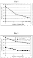
Fig. 8 illustrates an example of changes per day of the electromotive force to a similarly produced solid-electrode-type potassium ISE, which uses a mixture of natural graphite and paraffin oil as a base electrode, against a 100 mmol/l potassium chloride aqueous solution. It is found that the electromotive force gradually decreases with each day. This is estimated to be due to impurities in the natural graphite and the diffusion of paraffin oil in the base electrode into the ion-sensitive membrane. - As a countermeasure against impurities in the graphite, synthetic graphite (CAS. No. 1333-86-4) was used in place of the natural graphite.
Fig. 9 illustrates the results. It is found that the use of the synthetic graphite allows a reduction of a potential. This is considered to be due to the influence of carbon, which has various functional groups on its surface, of the natural graphite. - As a countermeasure against the diffusion of paraffin oil into the ion-sensitive membrane, a plasticizer that is the main component of the ion-sensitive membrane (in this case, oNPOE) was used in place of the paraffin oil.
Fig. 10 illustrates the results. It is found that the reduction in the potentials is suppressed to 1/4. This is estimated to be due to the reason that the diffusion of oil was suppressed as the same oil was used for the base electrode and the ion-sensitive membrane. If the plasticizer used for the ion-sensitive membrane is a different plasticizer such as DOA, DOP, or DOS as described in Pure Appl. Chem., Vol. 72, No. 10, pp. 1851-2082, 2000, the same effect is obtained by using the same plasticizer as that of the ion-sensitive membrane for the base electrode. -
Fig. 11 illustrates examples of changes per day of the electromotive force of a solid-electrode-type ISE, which is formed using a mixture of synthetic graphite and a plasticizer (in this case, oNPOE) or a mixture of synthetic graphite, a plasticizer, and a salt of a hydrophobic anion (in this case, NaTFPB), and a ligand (in this case, Bis(12-crown-4)), as a base electrode, and uses a similar sodium selective membrane to that described above for the sensitive membrane, against a 100 mmol/l sodium chloride aqueous solution. If a mixture of synthetic graphite and a plasticizer was used for the base electrode, the standard-deviation, which had been as low as 7.3 mV just after the preparation of the ISE, increased to 28 mV after 30 days have passed. In contrast, if a mixture of synthetic graphite, a plasticizer, a salt, and a ligand was used for the base electrode, the standard deviation, which had been as low as 2.3 mV just after the preparation of the ISE, remained as low as 3.9 mV even after 30 days has passed. This is estimated to be due to the reason that as the base electrode contains the same substances as the salt and the ligand contained in the sensitive membrane at the same concentrations, diffusion of the salt and the ligand was suppressed. As the salt contained in each of the base electrode and the sensitive membrane, it is possible to use a salt of a hydrophobic anion, such as KTFPB, KTmClPB, KTPB, KTpClPB, NaTFPB, or NaTpClPB described in Pure Appl. Chem., Vol. 72, No. 10; pp. 1851-2082, 2000. As the ligand (substance that selectively binds to a measurement target) contained in each of the base electrode and the sensitive membrane, it is possible to use Valinomycin described in Pure Appl. Chem., Vol. 72, No. 10, pp. 1851-2082, 2000, a crown ether compound, or their equivalents. - When a plasticizer is used as the liquid oil, the concentration in terms of weight% of the plasticizer in the sensitive membrane is 33% or more in order to prevent a significant reduction in the resistance, and is 70% or less in order to prevent a significant reduction in the mechanical strength, and is, depending on cases, in the range of 40% to 70%, 50% to 70%, or 60% to 70%, or preferably be 66% in order to reduce the resistance. In that case, the concentration in terms of weight% of the plasticizer in the base electrode is in the range of 33% to 80%, 40% to 80%, 50% to 80%, or 60% to 80%, or preferably, 66% in keeping with the concentration of the plasticizer in the sensitive membrane. Preferably, the ratio, in terms of weight%, between the concentration of the plasticizer in the sensitive membrane and the concentration of the plasticizer in the base electrode is within ±30%, ±20%, ±10%, ±5%, ±3%, or ±1%, or preferably, within ±1%.
-
Fig. 12 illustrates an example of measuring the electrolyte concentration using the solid-electrode-type ISE in accordance with the present invention. A mixture of natural graphite (CAS. No. 7782-42-5) and a fluorine-based polymer (FOMBLIN(R)) was used for the base electrode, and the aforementioned potassium selective membrane was used for the sensitive membrane. When a potassium chloride aqueous solution was measured under a condition of 25°C, a potential response of 58.4 mV/decade, which is identical to the theoretical value, was obtained. By using a fluorine-based polymer for the base electrode, it is possible to prevent a component, which can cause a potential fluctuation, in the sensitive membrane from being diffused into the base electrode. Meanwhile,Fig. 13 can confirm that the response to monovalent cations, which has been observed inFig. 6 , is maintained.Fig. 13 illustrates a result of conducting measurement in a 100 mmol/l potassium chloride aqueous solution using a potentiostat, and using a mixture of graphite and a fluorine-based polymer for a working electrode; a silver-silver chloride reference electrode, which uses saturated potassium chloride as an internal solution, for a reference electrode; and a platinum electrode for a counter electrode. Current peaks were observed at around -0.4 V and -0.2 V. - When a fluorine-based polymer is used as the liquid oil, the concentration in terms of weight% of a fluorine-based polymer in the base electrode is 33% to 80%, 40% to 80%, 50% to 80%, or 60% to 80%, or preferably, 66% in accordance with the concentration of the plasticizer in the sensitive membrane.
-
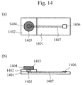
Fig. 14 shows schematic diagrams illustrating another example of the solid-electrode-type ISE in accordance with the present invention. Anelectrode substrate 1401 includes anelectrode 1405 and a terminal 1406, and theelectrode 1405 is electrically connected to the terminal 1406 with awire 1407. Theelectrode substrate 1401 includes a well 1402, and thewell 1402 is filled with abase electrode 1403, and further, an ion-sensitive membrane 1404 is arranged on thebase electrode 1403. When the ISE is brought into contact with a solution to be measured together with a reference electrode, and a potential difference between the ISE and the reference electrode is measured, it is possible to determine the concentration of ions that are the measurement targets with the ion-sensitive membrane 1404. For theelectrode substrate 1401, it is possible to use a silicon substrate or a resin substrate such as polypropylene (PP), polyethylene (PE), polycarbonate (PC), polyethylene terephthalate (PET), or polyvinyl chloride (PVC). If theelectrode substrate 1401 is a silicon substrate, theelectrode 1405, the terminal 1406, and thewire 1407 can be found using conductive metal or conductive polysilicon. If theelectrode substrate 1401 is resin, theelectrode 1405, the terminal 1406, and thewire 1407 can be formed using conductive metal, metal paste, or carbon paste. Thewell 1402 is preferably formed using resin. If the pion-sensitive membrane 1404 contains PVC, it is possible to increase the degree of adhesion between the well 1402 and the ion-sensitive membrane 1404 by using PVC for thewell 1402. -
Fig. 15 illustrates examples of a system using an electrolyte concentration measuring device. A biochemicalautomatic analysis apparatus 1501 shown inFig. 15(a) mainly includes a biochemical measuring device for optical measurement and an electrolyte concentration measuring device. The biochemicalautomatic analysis apparatus 1501 can be operated via an operating unit. InFig. 15(b) , devices, such as an electrolyte concentration measuring device, a biochemical measuring device, and an immunoassay device, are independent of each other, and a sample is exchanged between such devices and a sample conveying device. Each device can be operated via an operating unit. If an instruction to measure an ion concentration in a sample is sent from the operating unit, the specified sample is carried into the electrolyte concentration measuring devices in each ofFigs. 15(a) and 15(b) , so that the ion concentration is measured and results thereof are output. - The present invention is not limited to the aforementioned embodiments and includes various modifications. For example, although the aforementioned embodiments have been specifically described to clearly illustrate the present invention, the present invention need not include all of the configurations described in the embodiments. It is possible to replace a part of a structure of an embodiment with a structure of another embodiment. In addition, it is also possible to add, to a structure of an embodiment, a structure of another embodiment. Further, it is also possible to, for a part of a structure of each embodiment, add, remove, or substitute a structure of another embodiment.
-
- 101
- Cartridge of ISE
- 102
- Flow channel
- 103
- Platinum wire
- 104
- Mixture of graphite and liquid oil
- 105
- Sensitive membrane
- 106
- Cover
- 201
- Cartridge of ISE
- 202
- Flow channel
- 203
- Silver-silver chloride electrode
- 204
- Internal solution
- 205
- Sensitive membrane
- 301, 401
- Measuring unit
- 302, 402
- Control unit
- 303, 403
- Operation recording unit
- 304, 404
- Output unit
- 311, 411
- Dilution tank
- 312, 412
- Sample dispensing nozzle
- 313, 413
- Diluent dispensing nozzle
- 314, 414
- Internal-standard-solution dispensing nozzle
- 315,415
- Suction nozzle
- 316, 321, 416, 420, 423, 426, 428
- Pipe
- 317, 419
- Sodium ISE
- 318, 418
- Potassium ISE
- 319, 417
- Chlorine ISE
- 320, 424
- Reference electrode
- 322, 429
- Pump
- 323, 430
- Potential measuring unit
- 1401
- Electrode substrate
- 1402
- Well
- 1403
- Base electrode
- 1404
- Ion-sensitive membrane
- 1405
- Electrode
- 1406
- Terminal
- 1407
- Wire
- 1501
- Biochemical automatic analysis apparatus
Claims (9)
- An electrode for selectively detecting an ion as a measurement target in a measurement solution, the electrode comprising:an ion-sensitive membrane adapted to be in contact with the measurement solution;a mixture of graphite and liquid oil, the mixture being in contact with the ion-sensitive membrane; anda conductor in contact with the mixture of graphite and liquid oil.
- The electrode according to claim 1, wherein
the ion-sensitive membrane includes a plasticizer, and
the liquid oil includes the plasticizer. - The electrode according to claim 2, wherein a relative difference between a weight ratio of the plasticizer included in the ion-sensitive membrane and a weight ratio of the plasticizer included in the mixture of graphite and liquid oil is 30% or less.
- The electrode according to claim 2, wherein
the ion-sensitive membrane includes a hydrophobic anion, and
the mixture of graphite and liquid oil includes the hydrophobic anion. - The electrode according to claim 2, wherein
the ion-sensitive membrane includes a substance that selectively binds to the ion as the measurement target, and
the mixture of graphite and liquid oil includes the substance that selectively binds to the ion as the measurement target. - The electrode according to claim 1, wherein the liquid oil is a fluorine-based polymer or fluorine-based oil.
- The electrode according to claim 1, wherein the graphite is synthetic graphite.
- An electrode for selectively detecting an ion as a measurement target in a measurement solution, the electrode comprising:an electrode substrate containing silicon or resin;a conductive electrode formed on the electrode substrate;a mixture of graphite and liquid oil, the mixture being in contact with the conductive electrode; andan ion-sensitive membrane in contact with the mixture of graphite and liquid oil.
- A measuring device for measuring a concentration of ions in a measurement solution, the measuring device comprising:a plurality of electrodes configured to selectively detect the ions as measurement targets in the measurement solution;an ion-sensitive membrane adapted to be in contact with some of all of the electrodes;a mixture of graphite and liquid oil, the mixture being in contact with the ion-sensitive membrane; anda conductor in contact with the mixture of graphite and liquid oil.
Applications Claiming Priority (2)
| Application Number | Priority Date | Filing Date | Title |
|---|---|---|---|
| JP2013205646A JP6312396B2 (en) | 2013-09-30 | 2013-09-30 | Ion selective electrode |
| PCT/JP2014/069792 WO2015045606A1 (en) | 2013-09-30 | 2014-07-28 | Ion-selective electrode |
Publications (3)
| Publication Number | Publication Date |
|---|---|
| EP3054290A1 true EP3054290A1 (en) | 2016-08-10 |
| EP3054290A4 EP3054290A4 (en) | 2017-06-21 |
| EP3054290B1 EP3054290B1 (en) | 2019-05-29 |
Family
ID=52742763
Family Applications (1)
| Application Number | Title | Priority Date | Filing Date |
|---|---|---|---|
| EP14849328.1A Active EP3054290B1 (en) | 2013-09-30 | 2014-07-28 | Ion-selective electrode |
Country Status (5)
| Country | Link |
|---|---|
| US (1) | US9885683B2 (en) |
| EP (1) | EP3054290B1 (en) |
| JP (1) | JP6312396B2 (en) |
| CN (1) | CN105531584B (en) |
| WO (1) | WO2015045606A1 (en) |
Cited By (3)
| Publication number | Priority date | Publication date | Assignee | Title |
|---|---|---|---|---|
| EP3351931A4 (en) * | 2015-09-14 | 2019-08-14 | Hitachi High-Technologies Corporation | ION SELECTIVE ELECTRODE, MANUFACTURING METHOD THEREOF, AND CARTRIDGE |
| WO2019213520A1 (en) * | 2018-05-04 | 2019-11-07 | University Of Cincinnati | Membrane enhanced sensors |
| US11988627B2 (en) | 2021-02-09 | 2024-05-21 | Unisense A/S | Solid-contact ion-selective electrode |
Families Citing this family (13)
| Publication number | Priority date | Publication date | Assignee | Title |
|---|---|---|---|---|
| JP6827889B2 (en) * | 2017-07-18 | 2021-02-10 | 株式会社日立ハイテク | Ion-selective electrodes, electrolyte measuring devices, and electrolyte measuring systems |
| EP4234718A3 (en) | 2018-04-26 | 2023-11-29 | Pacific Biosciences Of California, Inc. | Methods and compositions for stabilizing nucleic acid-nucleotide-polymerase complexes |
| JP7150981B2 (en) * | 2019-04-10 | 2022-10-11 | 株式会社日立ハイテク | Ion-selective electrode and electrolyte concentration measuring device |
| CN109975376B (en) * | 2019-04-17 | 2021-06-22 | 中国科学院海洋研究所 | A kind of highly flexible all-solid-state sulfur ion selective electrode and preparation method thereof |
| CN110632144B (en) * | 2019-09-16 | 2020-11-10 | 西安交通大学 | All-solid-state ion selective electrode for detecting potassium fertilize and preparation method thereof |
| EP4073499A4 (en) * | 2019-12-11 | 2023-01-11 | Siemens Healthcare Diagnostics, Inc. | PHOTOCURABLE REAGENT(S) FOR FORMING ONE OR MORE CHLORIDE ION SELECTIVE SENSORS AND METHODS OF PRODUCING AND USING THEREOF |
| EP4090957A1 (en) * | 2020-01-13 | 2022-11-23 | Beckman Coulter, Inc. | Solid state ion selective electrodes |
| JP7573620B2 (en) * | 2020-01-13 | 2024-10-25 | ベックマン コールター, インコーポレイテッド | Solid-state ion-selective electrodes |
| US12442792B2 (en) | 2020-03-03 | 2025-10-14 | Horiba Advanced Techno, Co., Ltd. | Ion-selective electrode |
| JP7716317B2 (en) * | 2020-12-01 | 2025-07-31 | 株式会社 堀場アドバンスドテクノ | Ion selective electrode and ion concentration measuring device |
| DE102021116153A1 (en) * | 2021-06-22 | 2022-12-22 | Prominent Gmbh | Process for the optical activation of the sensor surface, especially for zero chlorine sensors |
| CN121358700A (en) * | 2023-07-14 | 2026-01-16 | 雷迪奥米特医学公司 | Methods for operating sensor devices |
| WO2025016863A1 (en) * | 2023-07-14 | 2025-01-23 | Radiometer Medical Aps | Sensor device |
Family Cites Families (15)
| Publication number | Priority date | Publication date | Assignee | Title |
|---|---|---|---|---|
| US4454007A (en) * | 1983-01-27 | 1984-06-12 | E. I. Du Pont De Nemours And Company | Ion-selective layered sensor and methods of making and using the same |
| JPH05164725A (en) * | 1991-12-18 | 1993-06-29 | Toto Ltd | Biosensor |
| JP3307687B2 (en) * | 1992-08-31 | 2002-07-24 | 鈴木 孝治 | Ion-selective coordination molecules and ion sensors |
| JP3812049B2 (en) | 1997-05-15 | 2006-08-23 | 株式会社日立製作所 | Chlorine ion sensitive membrane and method for producing the same |
| JPH11132991A (en) | 1997-10-29 | 1999-05-21 | Hitachi Ltd | Ion-selective electrode and method for producing the same |
| JP2000146897A (en) * | 1998-11-13 | 2000-05-26 | Kohjin Co Ltd | Electrode and measuring method of sulfidryl compound using the electrode |
| DE10018750C2 (en) * | 1999-04-23 | 2003-03-27 | Kurt Schwabe Inst Fuer Mess Un | Fixed contact ion-selective glass electrode and process for its production |
| JP4178357B2 (en) * | 2001-02-28 | 2008-11-12 | 東洋紡績株式会社 | Measuring method of polyphenol |
| JP3625448B2 (en) | 2002-01-11 | 2005-03-02 | 株式会社日立ハイテクノロジーズ | Ion sensor and biochemical automatic analyzer using the same |
| JP2003207481A (en) * | 2002-01-11 | 2003-07-25 | Jeol Ltd | Electrolyte measuring device |
| CN100422727C (en) | 2002-05-21 | 2008-10-01 | 株式会社百利达 | Electrochemical sensors |
| AT413766B8 (en) * | 2003-05-15 | 2006-06-15 | Hoffmann La Roche | POTENTIOMETRIC, ION-SELECTIVE ELECTRODE |
| EP1745280B1 (en) | 2004-04-27 | 2022-09-07 | PION Inc. | Potentiometric electrode with a gradient polymer comprising conductive particles and ionophore molecules, its manufacture and use |
| WO2006127963A2 (en) * | 2005-05-26 | 2006-11-30 | Regents Of The University Of Minnesota | Chemical sensor |
| CN102980931B (en) | 2012-11-23 | 2014-12-31 | 浙江大学 | All-solid-state selective electrode based on functional ion liquid and preparation method of all-solid-state selective electrode |
-
2013
- 2013-09-30 JP JP2013205646A patent/JP6312396B2/en active Active
-
2014
- 2014-07-28 WO PCT/JP2014/069792 patent/WO2015045606A1/en not_active Ceased
- 2014-07-28 US US15/021,400 patent/US9885683B2/en active Active
- 2014-07-28 EP EP14849328.1A patent/EP3054290B1/en active Active
- 2014-07-28 CN CN201480050487.2A patent/CN105531584B/en active Active
Cited By (6)
| Publication number | Priority date | Publication date | Assignee | Title |
|---|---|---|---|---|
| EP3351931A4 (en) * | 2015-09-14 | 2019-08-14 | Hitachi High-Technologies Corporation | ION SELECTIVE ELECTRODE, MANUFACTURING METHOD THEREOF, AND CARTRIDGE |
| US10871464B2 (en) | 2015-09-14 | 2020-12-22 | Hitachi High-Tech Corporation | Ion-selective electrode, method of manufacture thereof, and cartridge |
| WO2019213520A1 (en) * | 2018-05-04 | 2019-11-07 | University Of Cincinnati | Membrane enhanced sensors |
| CN112166317A (en) * | 2018-05-04 | 2021-01-01 | 辛辛那提大学 | Membrane Enhanced Sensor |
| US12259352B2 (en) | 2018-05-04 | 2025-03-25 | University Of Cincinnati | Membrane enhanced sensors |
| US11988627B2 (en) | 2021-02-09 | 2024-05-21 | Unisense A/S | Solid-contact ion-selective electrode |
Also Published As
| Publication number | Publication date |
|---|---|
| US9885683B2 (en) | 2018-02-06 |
| JP6312396B2 (en) | 2018-04-18 |
| JP2015068796A (en) | 2015-04-13 |
| CN105531584B (en) | 2018-05-04 |
| WO2015045606A1 (en) | 2015-04-02 |
| EP3054290B1 (en) | 2019-05-29 |
| US20160223486A1 (en) | 2016-08-04 |
| CN105531584A (en) | 2016-04-27 |
| EP3054290A4 (en) | 2017-06-21 |
Similar Documents
| Publication | Publication Date | Title |
|---|---|---|
| US9885683B2 (en) | Ion-selective electrode | |
| EP0512070A1 (en) | Multi-analyte sensing electrolytic cell | |
| JPH0633063U (en) | Graphite-based solid polymer membrane ion-selective electrode | |
| CN102980931B (en) | All-solid-state selective electrode based on functional ion liquid and preparation method of all-solid-state selective electrode | |
| CN103424451A (en) | Card type potassium ion sensor and method for preparing card type potassium ion sensor | |
| CN110133084A (en) | A kind of Integrated electrode detection card and preparation method thereof that can detect magnesium, chloride ion simultaneously | |
| ES2716199T3 (en) | System and method for electrochemical detection of silica species | |
| CN109142490A (en) | All-solid sodium ion selective sensor and its preparation and application | |
| KR20120010386A (en) | Method for producing an amperometric based micro-ion selective electrode, a method for producing an ampereometric based micro-ion selective electrode and a method for electrochemically quantifying ion concentration using the same | |
| Miyahara et al. | Shift and drift of electromotive forces of solid-state electrodes with ion-selective liquid membranes | |
| US20160195491A1 (en) | Ion selective electrode | |
| Novakovskii et al. | Lipophilicity Criteria for Ionic Components Used in Liquid-Junction-Free Reference Electrodes | |
| Oyama et al. | Ion-selective electrodes based on bilayer film coating | |
| Masadome et al. | Microfluidic polymer chip integrated with an ISFET detector for cationic surfactant assay in dental rinses | |
| Marple et al. | Potentiometry: pH and Ion-Selective Electrodes | |
| US8436622B2 (en) | Method for measurement of content of water or organic acid in polar organic solvent, and apparatus for the method | |
| Masadome et al. | Microfluidic polymer chip with an embedded ion-selective electrode detector for nitrate-ion assay in environmental samples | |
| Hidouri et al. | High sensitive and selective hydrogen phosphate ISFET based on polyvinyl chloride membrane | |
| Herrmann et al. | Miniaturized sensor module for in-situ control of waters | |
| Guagneli | Novel design of a flow-through potentiometric sensing device | |
| Ciosek et al. | Potentiometric studies and various applications of solid state electrodes based on silicon and epoxy glass structures–an overview | |
| Wang et al. | Self-Calibrated Ion-Selective Electrodes | |
| JP4216846B2 (en) | Electrodes for electrochemical measurements and electrochemical measurement methods | |
| Dimitrakopoulos | Portable monitors for flow injection analysis with potentiometric multiple ion sensors | |
| Telting-Diaz et al. | a Potentiometry |
Legal Events
| Date | Code | Title | Description |
|---|---|---|---|
| PUAI | Public reference made under article 153(3) epc to a published international application that has entered the european phase |
Free format text: ORIGINAL CODE: 0009012 |
|
| 17P | Request for examination filed |
Effective date: 20160318 |
|
| AK | Designated contracting states |
Kind code of ref document: A1 Designated state(s): AL AT BE BG CH CY CZ DE DK EE ES FI FR GB GR HR HU IE IS IT LI LT LU LV MC MK MT NL NO PL PT RO RS SE SI SK SM TR |
|
| AX | Request for extension of the european patent |
Extension state: BA ME |
|
| DAX | Request for extension of the european patent (deleted) | ||
| A4 | Supplementary search report drawn up and despatched |
Effective date: 20170524 |
|
| RIC1 | Information provided on ipc code assigned before grant |
Ipc: G01N 27/30 20060101ALN20170518BHEP Ipc: G01N 27/333 20060101AFI20170518BHEP |
|
| STAA | Information on the status of an ep patent application or granted ep patent |
Free format text: STATUS: EXAMINATION IS IN PROGRESS |
|
| RIC1 | Information provided on ipc code assigned before grant |
Ipc: G01N 27/333 20060101AFI20180427BHEP Ipc: G01N 27/30 20060101ALN20180427BHEP |
|
| 17Q | First examination report despatched |
Effective date: 20180515 |
|
| RIC1 | Information provided on ipc code assigned before grant |
Ipc: G01N 27/333 20060101AFI20180928BHEP Ipc: G01N 27/30 20060101ALN20180928BHEP |
|
| RIC1 | Information provided on ipc code assigned before grant |
Ipc: G01N 27/30 20060101ALN20181015BHEP Ipc: G01N 27/333 20060101AFI20181015BHEP |
|
| GRAP | Despatch of communication of intention to grant a patent |
Free format text: ORIGINAL CODE: EPIDOSNIGR1 |
|
| STAA | Information on the status of an ep patent application or granted ep patent |
Free format text: STATUS: GRANT OF PATENT IS INTENDED |
|
| INTG | Intention to grant announced |
Effective date: 20181123 |
|
| GRAS | Grant fee paid |
Free format text: ORIGINAL CODE: EPIDOSNIGR3 |
|
| GRAA | (expected) grant |
Free format text: ORIGINAL CODE: 0009210 |
|
| STAA | Information on the status of an ep patent application or granted ep patent |
Free format text: STATUS: THE PATENT HAS BEEN GRANTED |
|
| RAP1 | Party data changed (applicant data changed or rights of an application transferred) |
Owner name: HITACHI HIGH-TECHNOLOGIES CORPORATION |
|
| AK | Designated contracting states |
Kind code of ref document: B1 Designated state(s): AL AT BE BG CH CY CZ DE DK EE ES FI FR GB GR HR HU IE IS IT LI LT LU LV MC MK MT NL NO PL PT RO RS SE SI SK SM TR |
|
| REG | Reference to a national code |
Ref country code: GB Ref legal event code: FG4D |
|
| REG | Reference to a national code |
Ref country code: CH Ref legal event code: EP |
|
| REG | Reference to a national code |
Ref country code: AT Ref legal event code: REF Ref document number: 1138568 Country of ref document: AT Kind code of ref document: T Effective date: 20190615 |
|
| REG | Reference to a national code |
Ref country code: DE Ref legal event code: R096 Ref document number: 602014047651 Country of ref document: DE |
|
| REG | Reference to a national code |
Ref country code: IE Ref legal event code: FG4D |
|
| REG | Reference to a national code |
Ref country code: NL Ref legal event code: MP Effective date: 20190529 |
|
| REG | Reference to a national code |
Ref country code: LT Ref legal event code: MG4D |
|
| PG25 | Lapsed in a contracting state [announced via postgrant information from national office to epo] |
Ref country code: AL Free format text: LAPSE BECAUSE OF FAILURE TO SUBMIT A TRANSLATION OF THE DESCRIPTION OR TO PAY THE FEE WITHIN THE PRESCRIBED TIME-LIMIT Effective date: 20190529 Ref country code: SE Free format text: LAPSE BECAUSE OF FAILURE TO SUBMIT A TRANSLATION OF THE DESCRIPTION OR TO PAY THE FEE WITHIN THE PRESCRIBED TIME-LIMIT Effective date: 20190529 Ref country code: FI Free format text: LAPSE BECAUSE OF FAILURE TO SUBMIT A TRANSLATION OF THE DESCRIPTION OR TO PAY THE FEE WITHIN THE PRESCRIBED TIME-LIMIT Effective date: 20190529 Ref country code: HR Free format text: LAPSE BECAUSE OF FAILURE TO SUBMIT A TRANSLATION OF THE DESCRIPTION OR TO PAY THE FEE WITHIN THE PRESCRIBED TIME-LIMIT Effective date: 20190529 Ref country code: NO Free format text: LAPSE BECAUSE OF FAILURE TO SUBMIT A TRANSLATION OF THE DESCRIPTION OR TO PAY THE FEE WITHIN THE PRESCRIBED TIME-LIMIT Effective date: 20190829 Ref country code: PT Free format text: LAPSE BECAUSE OF FAILURE TO SUBMIT A TRANSLATION OF THE DESCRIPTION OR TO PAY THE FEE WITHIN THE PRESCRIBED TIME-LIMIT Effective date: 20190930 Ref country code: ES Free format text: LAPSE BECAUSE OF FAILURE TO SUBMIT A TRANSLATION OF THE DESCRIPTION OR TO PAY THE FEE WITHIN THE PRESCRIBED TIME-LIMIT Effective date: 20190529 Ref country code: LT Free format text: LAPSE BECAUSE OF FAILURE TO SUBMIT A TRANSLATION OF THE DESCRIPTION OR TO PAY THE FEE WITHIN THE PRESCRIBED TIME-LIMIT Effective date: 20190529 |
|
| PG25 | Lapsed in a contracting state [announced via postgrant information from national office to epo] |
Ref country code: RS Free format text: LAPSE BECAUSE OF FAILURE TO SUBMIT A TRANSLATION OF THE DESCRIPTION OR TO PAY THE FEE WITHIN THE PRESCRIBED TIME-LIMIT Effective date: 20190529 Ref country code: GR Free format text: LAPSE BECAUSE OF FAILURE TO SUBMIT A TRANSLATION OF THE DESCRIPTION OR TO PAY THE FEE WITHIN THE PRESCRIBED TIME-LIMIT Effective date: 20190830 Ref country code: BG Free format text: LAPSE BECAUSE OF FAILURE TO SUBMIT A TRANSLATION OF THE DESCRIPTION OR TO PAY THE FEE WITHIN THE PRESCRIBED TIME-LIMIT Effective date: 20190829 Ref country code: LV Free format text: LAPSE BECAUSE OF FAILURE TO SUBMIT A TRANSLATION OF THE DESCRIPTION OR TO PAY THE FEE WITHIN THE PRESCRIBED TIME-LIMIT Effective date: 20190529 |
|
| REG | Reference to a national code |
Ref country code: AT Ref legal event code: MK05 Ref document number: 1138568 Country of ref document: AT Kind code of ref document: T Effective date: 20190529 |
|
| PG25 | Lapsed in a contracting state [announced via postgrant information from national office to epo] |
Ref country code: NL Free format text: LAPSE BECAUSE OF FAILURE TO SUBMIT A TRANSLATION OF THE DESCRIPTION OR TO PAY THE FEE WITHIN THE PRESCRIBED TIME-LIMIT Effective date: 20190529 Ref country code: DK Free format text: LAPSE BECAUSE OF FAILURE TO SUBMIT A TRANSLATION OF THE DESCRIPTION OR TO PAY THE FEE WITHIN THE PRESCRIBED TIME-LIMIT Effective date: 20190529 Ref country code: AT Free format text: LAPSE BECAUSE OF FAILURE TO SUBMIT A TRANSLATION OF THE DESCRIPTION OR TO PAY THE FEE WITHIN THE PRESCRIBED TIME-LIMIT Effective date: 20190529 Ref country code: EE Free format text: LAPSE BECAUSE OF FAILURE TO SUBMIT A TRANSLATION OF THE DESCRIPTION OR TO PAY THE FEE WITHIN THE PRESCRIBED TIME-LIMIT Effective date: 20190529 Ref country code: SK Free format text: LAPSE BECAUSE OF FAILURE TO SUBMIT A TRANSLATION OF THE DESCRIPTION OR TO PAY THE FEE WITHIN THE PRESCRIBED TIME-LIMIT Effective date: 20190529 Ref country code: RO Free format text: LAPSE BECAUSE OF FAILURE TO SUBMIT A TRANSLATION OF THE DESCRIPTION OR TO PAY THE FEE WITHIN THE PRESCRIBED TIME-LIMIT Effective date: 20190529 Ref country code: CZ Free format text: LAPSE BECAUSE OF FAILURE TO SUBMIT A TRANSLATION OF THE DESCRIPTION OR TO PAY THE FEE WITHIN THE PRESCRIBED TIME-LIMIT Effective date: 20190529 |
|
| PG25 | Lapsed in a contracting state [announced via postgrant information from national office to epo] |
Ref country code: MC Free format text: LAPSE BECAUSE OF FAILURE TO SUBMIT A TRANSLATION OF THE DESCRIPTION OR TO PAY THE FEE WITHIN THE PRESCRIBED TIME-LIMIT Effective date: 20190529 Ref country code: IT Free format text: LAPSE BECAUSE OF FAILURE TO SUBMIT A TRANSLATION OF THE DESCRIPTION OR TO PAY THE FEE WITHIN THE PRESCRIBED TIME-LIMIT Effective date: 20190529 Ref country code: SM Free format text: LAPSE BECAUSE OF FAILURE TO SUBMIT A TRANSLATION OF THE DESCRIPTION OR TO PAY THE FEE WITHIN THE PRESCRIBED TIME-LIMIT Effective date: 20190529 |
|
| REG | Reference to a national code |
Ref country code: CH Ref legal event code: PL |
|
| REG | Reference to a national code |
Ref country code: DE Ref legal event code: R097 Ref document number: 602014047651 Country of ref document: DE |
|
| PG25 | Lapsed in a contracting state [announced via postgrant information from national office to epo] |
Ref country code: TR Free format text: LAPSE BECAUSE OF FAILURE TO SUBMIT A TRANSLATION OF THE DESCRIPTION OR TO PAY THE FEE WITHIN THE PRESCRIBED TIME-LIMIT Effective date: 20190529 |
|
| PLBE | No opposition filed within time limit |
Free format text: ORIGINAL CODE: 0009261 |
|
| STAA | Information on the status of an ep patent application or granted ep patent |
Free format text: STATUS: NO OPPOSITION FILED WITHIN TIME LIMIT |
|
| REG | Reference to a national code |
Ref country code: BE Ref legal event code: MM Effective date: 20190731 |
|
| GBPC | Gb: european patent ceased through non-payment of renewal fee |
Effective date: 20190829 |
|
| PG25 | Lapsed in a contracting state [announced via postgrant information from national office to epo] |
Ref country code: PL Free format text: LAPSE BECAUSE OF FAILURE TO SUBMIT A TRANSLATION OF THE DESCRIPTION OR TO PAY THE FEE WITHIN THE PRESCRIBED TIME-LIMIT Effective date: 20190529 |
|
| 26N | No opposition filed |
Effective date: 20200303 |
|
| PG25 | Lapsed in a contracting state [announced via postgrant information from national office to epo] |
Ref country code: CH Free format text: LAPSE BECAUSE OF NON-PAYMENT OF DUE FEES Effective date: 20190731 Ref country code: LU Free format text: LAPSE BECAUSE OF NON-PAYMENT OF DUE FEES Effective date: 20190728 Ref country code: SI Free format text: LAPSE BECAUSE OF FAILURE TO SUBMIT A TRANSLATION OF THE DESCRIPTION OR TO PAY THE FEE WITHIN THE PRESCRIBED TIME-LIMIT Effective date: 20190529 Ref country code: LI Free format text: LAPSE BECAUSE OF NON-PAYMENT OF DUE FEES Effective date: 20190731 Ref country code: BE Free format text: LAPSE BECAUSE OF NON-PAYMENT OF DUE FEES Effective date: 20190731 |
|
| REG | Reference to a national code |
Ref country code: DE Ref legal event code: R082 Ref document number: 602014047651 Country of ref document: DE Representative=s name: MERH-IP MATIAS ERNY REICHL HOFFMANN PATENTANWA, DE Ref country code: DE Ref legal event code: R081 Ref document number: 602014047651 Country of ref document: DE Owner name: HITACHI HIGH-TECH CORPORATION, JP Free format text: FORMER OWNER: HITACHI HIGH-TECHNOLOGIES CORPORATION, TOKYO, JP |
|
| PG25 | Lapsed in a contracting state [announced via postgrant information from national office to epo] |
Ref country code: IE Free format text: LAPSE BECAUSE OF NON-PAYMENT OF DUE FEES Effective date: 20190728 |
|
| PG25 | Lapsed in a contracting state [announced via postgrant information from national office to epo] |
Ref country code: GB Free format text: LAPSE BECAUSE OF NON-PAYMENT OF DUE FEES Effective date: 20190829 |
|
| PG25 | Lapsed in a contracting state [announced via postgrant information from national office to epo] |
Ref country code: CY Free format text: LAPSE BECAUSE OF FAILURE TO SUBMIT A TRANSLATION OF THE DESCRIPTION OR TO PAY THE FEE WITHIN THE PRESCRIBED TIME-LIMIT Effective date: 20190529 |
|
| PG25 | Lapsed in a contracting state [announced via postgrant information from national office to epo] |
Ref country code: IS Free format text: LAPSE BECAUSE OF FAILURE TO SUBMIT A TRANSLATION OF THE DESCRIPTION OR TO PAY THE FEE WITHIN THE PRESCRIBED TIME-LIMIT Effective date: 20190929 |
|
| PG25 | Lapsed in a contracting state [announced via postgrant information from national office to epo] |
Ref country code: HU Free format text: LAPSE BECAUSE OF FAILURE TO SUBMIT A TRANSLATION OF THE DESCRIPTION OR TO PAY THE FEE WITHIN THE PRESCRIBED TIME-LIMIT; INVALID AB INITIO Effective date: 20140728 Ref country code: MT Free format text: LAPSE BECAUSE OF FAILURE TO SUBMIT A TRANSLATION OF THE DESCRIPTION OR TO PAY THE FEE WITHIN THE PRESCRIBED TIME-LIMIT Effective date: 20190529 |
|
| PG25 | Lapsed in a contracting state [announced via postgrant information from national office to epo] |
Ref country code: MK Free format text: LAPSE BECAUSE OF FAILURE TO SUBMIT A TRANSLATION OF THE DESCRIPTION OR TO PAY THE FEE WITHIN THE PRESCRIBED TIME-LIMIT Effective date: 20190529 |
|
| PGFP | Annual fee paid to national office [announced via postgrant information from national office to epo] |
Ref country code: FR Payment date: 20250610 Year of fee payment: 12 |
|
| PGFP | Annual fee paid to national office [announced via postgrant information from national office to epo] |
Ref country code: DE Payment date: 20250604 Year of fee payment: 12 |