EP3054255A1 - Heat exchanger and air conditioner - Google Patents
Heat exchanger and air conditioner Download PDFInfo
- Publication number
- EP3054255A1 EP3054255A1 EP14846790.5A EP14846790A EP3054255A1 EP 3054255 A1 EP3054255 A1 EP 3054255A1 EP 14846790 A EP14846790 A EP 14846790A EP 3054255 A1 EP3054255 A1 EP 3054255A1
- Authority
- EP
- European Patent Office
- Prior art keywords
- spaces
- refrigerant
- space
- heat exchanger
- collecting tube
- Prior art date
- Legal status (The legal status is an assumption and is not a legal conclusion. Google has not performed a legal analysis and makes no representation as to the accuracy of the status listed.)
- Granted
Links
Images








Classifications
-
- F—MECHANICAL ENGINEERING; LIGHTING; HEATING; WEAPONS; BLASTING
- F28—HEAT EXCHANGE IN GENERAL
- F28D—HEAT-EXCHANGE APPARATUS, NOT PROVIDED FOR IN ANOTHER SUBCLASS, IN WHICH THE HEAT-EXCHANGE MEDIA DO NOT COME INTO DIRECT CONTACT
- F28D1/00—Heat-exchange apparatus having stationary conduit assemblies for one heat-exchange medium only, the media being in contact with different sides of the conduit wall, in which the other heat-exchange medium is a large body of fluid, e.g. domestic or motor car radiators
- F28D1/02—Heat-exchange apparatus having stationary conduit assemblies for one heat-exchange medium only, the media being in contact with different sides of the conduit wall, in which the other heat-exchange medium is a large body of fluid, e.g. domestic or motor car radiators with heat-exchange conduits immersed in the body of fluid
- F28D1/04—Heat-exchange apparatus having stationary conduit assemblies for one heat-exchange medium only, the media being in contact with different sides of the conduit wall, in which the other heat-exchange medium is a large body of fluid, e.g. domestic or motor car radiators with heat-exchange conduits immersed in the body of fluid with tubular conduits
- F28D1/053—Heat-exchange apparatus having stationary conduit assemblies for one heat-exchange medium only, the media being in contact with different sides of the conduit wall, in which the other heat-exchange medium is a large body of fluid, e.g. domestic or motor car radiators with heat-exchange conduits immersed in the body of fluid with tubular conduits the conduits being straight
- F28D1/0535—Heat-exchange apparatus having stationary conduit assemblies for one heat-exchange medium only, the media being in contact with different sides of the conduit wall, in which the other heat-exchange medium is a large body of fluid, e.g. domestic or motor car radiators with heat-exchange conduits immersed in the body of fluid with tubular conduits the conduits being straight the conduits having a non-circular cross-section
- F28D1/05366—Assemblies of conduits connected to common headers, e.g. core type radiators
- F28D1/05391—Assemblies of conduits connected to common headers, e.g. core type radiators with multiple rows of conduits or with multi-channel conduits combined with a particular flow pattern, e.g. multi-row multi-stage radiators
-
- F—MECHANICAL ENGINEERING; LIGHTING; HEATING; WEAPONS; BLASTING
- F25—REFRIGERATION OR COOLING; COMBINED HEATING AND REFRIGERATION SYSTEMS; HEAT PUMP SYSTEMS; MANUFACTURE OR STORAGE OF ICE; LIQUEFACTION SOLIDIFICATION OF GASES
- F25B—REFRIGERATION MACHINES, PLANTS OR SYSTEMS; COMBINED HEATING AND REFRIGERATION SYSTEMS; HEAT PUMP SYSTEMS
- F25B13/00—Compression machines, plants or systems, with reversible cycle
-
- F—MECHANICAL ENGINEERING; LIGHTING; HEATING; WEAPONS; BLASTING
- F25—REFRIGERATION OR COOLING; COMBINED HEATING AND REFRIGERATION SYSTEMS; HEAT PUMP SYSTEMS; MANUFACTURE OR STORAGE OF ICE; LIQUEFACTION SOLIDIFICATION OF GASES
- F25B—REFRIGERATION MACHINES, PLANTS OR SYSTEMS; COMBINED HEATING AND REFRIGERATION SYSTEMS; HEAT PUMP SYSTEMS
- F25B39/00—Evaporators; Condensers
-
- F—MECHANICAL ENGINEERING; LIGHTING; HEATING; WEAPONS; BLASTING
- F28—HEAT EXCHANGE IN GENERAL
- F28D—HEAT-EXCHANGE APPARATUS, NOT PROVIDED FOR IN ANOTHER SUBCLASS, IN WHICH THE HEAT-EXCHANGE MEDIA DO NOT COME INTO DIRECT CONTACT
- F28D1/00—Heat-exchange apparatus having stationary conduit assemblies for one heat-exchange medium only, the media being in contact with different sides of the conduit wall, in which the other heat-exchange medium is a large body of fluid, e.g. domestic or motor car radiators
- F28D1/02—Heat-exchange apparatus having stationary conduit assemblies for one heat-exchange medium only, the media being in contact with different sides of the conduit wall, in which the other heat-exchange medium is a large body of fluid, e.g. domestic or motor car radiators with heat-exchange conduits immersed in the body of fluid
- F28D1/04—Heat-exchange apparatus having stationary conduit assemblies for one heat-exchange medium only, the media being in contact with different sides of the conduit wall, in which the other heat-exchange medium is a large body of fluid, e.g. domestic or motor car radiators with heat-exchange conduits immersed in the body of fluid with tubular conduits
- F28D1/047—Heat-exchange apparatus having stationary conduit assemblies for one heat-exchange medium only, the media being in contact with different sides of the conduit wall, in which the other heat-exchange medium is a large body of fluid, e.g. domestic or motor car radiators with heat-exchange conduits immersed in the body of fluid with tubular conduits the conduits being bent, e.g. in a serpentine or zig-zag
- F28D1/0471—Heat-exchange apparatus having stationary conduit assemblies for one heat-exchange medium only, the media being in contact with different sides of the conduit wall, in which the other heat-exchange medium is a large body of fluid, e.g. domestic or motor car radiators with heat-exchange conduits immersed in the body of fluid with tubular conduits the conduits being bent, e.g. in a serpentine or zig-zag the conduits having a non-circular cross-section
-
- F—MECHANICAL ENGINEERING; LIGHTING; HEATING; WEAPONS; BLASTING
- F28—HEAT EXCHANGE IN GENERAL
- F28F—DETAILS OF HEAT-EXCHANGE AND HEAT-TRANSFER APPARATUS, OF GENERAL APPLICATION
- F28F1/00—Tubular elements; Assemblies of tubular elements
- F28F1/10—Tubular elements and assemblies thereof with means for increasing heat-transfer area, e.g. with fins, with projections, with recesses
- F28F1/12—Tubular elements and assemblies thereof with means for increasing heat-transfer area, e.g. with fins, with projections, with recesses the means being only outside the tubular element
- F28F1/24—Tubular elements and assemblies thereof with means for increasing heat-transfer area, e.g. with fins, with projections, with recesses the means being only outside the tubular element and extending transversely
- F28F1/30—Tubular elements and assemblies thereof with means for increasing heat-transfer area, e.g. with fins, with projections, with recesses the means being only outside the tubular element and extending transversely the means being attachable to the element
-
- F—MECHANICAL ENGINEERING; LIGHTING; HEATING; WEAPONS; BLASTING
- F28—HEAT EXCHANGE IN GENERAL
- F28F—DETAILS OF HEAT-EXCHANGE AND HEAT-TRANSFER APPARATUS, OF GENERAL APPLICATION
- F28F1/00—Tubular elements; Assemblies of tubular elements
- F28F1/10—Tubular elements and assemblies thereof with means for increasing heat-transfer area, e.g. with fins, with projections, with recesses
- F28F1/12—Tubular elements and assemblies thereof with means for increasing heat-transfer area, e.g. with fins, with projections, with recesses the means being only outside the tubular element
- F28F1/24—Tubular elements and assemblies thereof with means for increasing heat-transfer area, e.g. with fins, with projections, with recesses the means being only outside the tubular element and extending transversely
- F28F1/32—Tubular elements and assemblies thereof with means for increasing heat-transfer area, e.g. with fins, with projections, with recesses the means being only outside the tubular element and extending transversely the means having portions engaging further tubular elements
- F28F1/325—Fins with openings
-
- F—MECHANICAL ENGINEERING; LIGHTING; HEATING; WEAPONS; BLASTING
- F28—HEAT EXCHANGE IN GENERAL
- F28F—DETAILS OF HEAT-EXCHANGE AND HEAT-TRANSFER APPARATUS, OF GENERAL APPLICATION
- F28F9/00—Casings; Header boxes; Auxiliary supports for elements; Auxiliary members within casings
- F28F9/02—Header boxes; End plates
- F28F9/0202—Header boxes having their inner space divided by partitions
-
- F—MECHANICAL ENGINEERING; LIGHTING; HEATING; WEAPONS; BLASTING
- F28—HEAT EXCHANGE IN GENERAL
- F28F—DETAILS OF HEAT-EXCHANGE AND HEAT-TRANSFER APPARATUS, OF GENERAL APPLICATION
- F28F9/00—Casings; Header boxes; Auxiliary supports for elements; Auxiliary members within casings
- F28F9/02—Header boxes; End plates
- F28F9/026—Header boxes; End plates with static flow control means, e.g. with means for uniformly distributing heat exchange media into conduits
- F28F9/027—Header boxes; End plates with static flow control means, e.g. with means for uniformly distributing heat exchange media into conduits in the form of distribution pipes
-
- F—MECHANICAL ENGINEERING; LIGHTING; HEATING; WEAPONS; BLASTING
- F28—HEAT EXCHANGE IN GENERAL
- F28F—DETAILS OF HEAT-EXCHANGE AND HEAT-TRANSFER APPARATUS, OF GENERAL APPLICATION
- F28F9/00—Casings; Header boxes; Auxiliary supports for elements; Auxiliary members within casings
- F28F9/02—Header boxes; End plates
- F28F9/026—Header boxes; End plates with static flow control means, e.g. with means for uniformly distributing heat exchange media into conduits
- F28F9/027—Header boxes; End plates with static flow control means, e.g. with means for uniformly distributing heat exchange media into conduits in the form of distribution pipes
- F28F9/0275—Header boxes; End plates with static flow control means, e.g. with means for uniformly distributing heat exchange media into conduits in the form of distribution pipes with multiple branch pipes
-
- F—MECHANICAL ENGINEERING; LIGHTING; HEATING; WEAPONS; BLASTING
- F28—HEAT EXCHANGE IN GENERAL
- F28F—DETAILS OF HEAT-EXCHANGE AND HEAT-TRANSFER APPARATUS, OF GENERAL APPLICATION
- F28F9/00—Casings; Header boxes; Auxiliary supports for elements; Auxiliary members within casings
- F28F9/02—Header boxes; End plates
- F28F9/026—Header boxes; End plates with static flow control means, e.g. with means for uniformly distributing heat exchange media into conduits
- F28F9/028—Header boxes; End plates with static flow control means, e.g. with means for uniformly distributing heat exchange media into conduits by using inserts for modifying the pattern of flow inside the header box, e.g. by using flow restrictors or permeable bodies or blocks with channels
-
- F—MECHANICAL ENGINEERING; LIGHTING; HEATING; WEAPONS; BLASTING
- F25—REFRIGERATION OR COOLING; COMBINED HEATING AND REFRIGERATION SYSTEMS; HEAT PUMP SYSTEMS; MANUFACTURE OR STORAGE OF ICE; LIQUEFACTION SOLIDIFICATION OF GASES
- F25B—REFRIGERATION MACHINES, PLANTS OR SYSTEMS; COMBINED HEATING AND REFRIGERATION SYSTEMS; HEAT PUMP SYSTEMS
- F25B39/00—Evaporators; Condensers
- F25B39/02—Evaporators
- F25B39/028—Evaporators having distributing means
Definitions
- the present invention relates to a heat exchanger and an air conditioning device.
- Heat exchangers of a design having a plurality of flat tubes, fins which are joined to the plurality of flat tubes, and header collecting tubes which are coupled respectively to the plurality of flat tubes at a one end side and another end side thereof, for bringing about heat exchange between a refrigerant flowing through the interior the flat tubes and air flowing to the outside of the flat tubes, are known in the prior art.
- the heat exchanger disclosed in Patent Literature 1 ( Japanese Laid-open Patent No. 2-219966 ) is configured such that a plurality of outflow tubes extending in a horizontal direction are connected at either end to header collecting tubes that respectively extend in a vertical direction.
- Patent Literature 1 The heat exchanger disclosed in Patent Literature 1 is directed to the problem that, in the interior of the header collecting tubes that extend in the vertical direction, liquid phase refrigerant of high specific gravity collects towards the bottom while gas phase refrigerant of low specific gravity collects towards the top, thereby giving rise to eccentric flow; in order to solve this problem, the feature of forming a throttle inside the header collecting tubes is proposed.
- Passing the refrigerant through the throttle formed in this manner facilitates mixing of the gas phase refrigerant and the liquid phase refrigerant, while at the same time improves the flow velocity, making it easy for the refrigerant to reach the top within the header collecting tubes, thereby minimizing eccentric flow of the refrigerant.
- the heat exchanger according to a first aspect of the present invention is provided with a plurality of flat tubes, a header collecting tube, and a plurality of fins.
- the plurality of flat tubes are arranged mutually.
- the header collecting tube has the one ends of the flat tubes connected thereto, and extends in a vertical direction.
- the plurality of fins are joined to the flat tubes.
- the header collecting tube has a loop structure.
- the loop structure includes partition members, inflow ports, upper communicating passages, and lower communicating passages. The partition members partition internal spaces into first spaces which are spaces to the side where the flat tubes are connected, and second spaces which are spaces to the side opposite from the side where the flat tubes are connected to the first space.
- the inflow ports are located in lower parts of the first spaces, and in the case of functioning as a refrigerant evaporator, prompt inflow of refrigerant so as to give rise to an ascending flow within the first spaces.
- the upper communicating passages are located in upper parts of the first spaces and the second spaces, and provide communication between the upper parts of the first spaces and the second spaces, thereby guiding the refrigerant which has ascended within the first spaces into the second spaces.
- the lower communicating passages are located in lower parts of the first spaces and the second spaces, provide communication between the lower parts of the first spaces and the second spaces, and by guiding the refrigerant in a direction other than vertical direction from the second spaces towards spaces above the inflow ports in the first spaces, guide the refrigerant from the first spaces to the second spaces, and return the refrigerant having descended through the second spaces from the second spaces to the first spaces.
- inlet port is used to include not only openings that are furnished to thin plate-shaped members, but where inflow passages formed to passage shape are provided, the outlets thereof as well.
- the "direction other than vertical direction" herein is not particularly limited provided that the direction is one leading from the second spaces to spaces above the inflow ports in the first spaces, and may include, for example, a horizontal direction leading from the second space side towards the first space side; a direction inclined towards the first space side from the second space side would also be acceptable.
- An incline of 60 degrees or less with respect to the horizontal direction would be an acceptable incline, as would one of 30 degrees or less; and an incline of -60 degrees or more with respect to the horizontal direction would be acceptable, as would one of -30 degrees or more.
- the internal spaces of the header collecting tube are partitioned by the partition members into the first spaces and the second spaces, whereby the area through which the refrigerant having flowed into the first spaces from the inflow ports passes while ascending through the first spaces can be made smaller, as compared with the case in which the first spaces and the second spaces are not partitioned by partition members.
- the refrigerant having flowed into the first spaces from the inflow ports can be made to ascend through the narrow spaces of the first spaces only, whereby the refrigerant can easily reach the upper parts of the internal spaces of the header collecting tubes without experiencing any significant drop in the velocity of ascension of the refrigerant through the first spaces. For this reason, even when the circulation rate of the refrigerant is a low circulation rate, sufficient flow of the refrigerant to the flat tubes arranged towards the top is possible.
- the header collecting tube has a loop structure that includes the inflow ports, the partition members, the upper communication passages, and the lower communication passages.
- a heat exchanger is the heat exchanger according to the first aspect of the present invention, wherein the lower communicating passages are disposed above the inflow ports, near the bottommost flat tubes above the inflow ports.
- the bottommost flat tubes above the inflow ports are those that are situated at bottommost locations among the flat tubes located above the inflow ports.
- the passages may be disposed above the inflow ports at locations at the same height as the bottommost flat tubes above the inflow ports, or at places therebelow. It is also acceptable for only the outlets of the lower communicating passages to be located above the inflow port and near the bottommost flat tubes above the inflow ports.
- the refrigerant having passed forcefully through the inflow ports is guided into the second spaces via the upper communicating passages in the upper parts of the first spaces, and after descending through the second spaces, passes through the lower communicating passages and towards the lower parts of the first spaces, making it possible to be sufficiently guided into the bottommost flat tubes above the inflow ports.
- a heat exchanger according to a third aspect of the present invention is the heat exchanger according to the first or second aspect of the present invention, wherein flow regulation spaces are formed at the bottoms of the first spaces and second spaces among the internal spaces.
- the first and second spaces and the flow regulation spaces are partitioned by flow regulation members.
- the inflow ports are furnished to the flow regulation members, in such a way that the passage cross section area of the refrigerant going from the flow regulation spaces towards the first spaces can be throttled.
- the refrigerant flowing from the flow regulation spaces below to the first spaces above can be passed through the inflow ports which are disposed so as to throttle the passage cross section area.
- the flow velocity of the flow of refrigerant passing from the flow regulation spaces to the first spaces through the inflow ports can be increased, and an ascending flow of the refrigerant through the first spaces can be easily produced.
- the first spaces, the second spaces, and the flow regulation spaces are disposed within the header collecting tube, there is no need to provide any arrangement, other than the header collecting tube, in order to produce an ascending flow of the refrigerant through the first spaces.
- a heat exchanger according to a fourth aspect of the present invention is the heat exchanger according to the third aspect of the present invention, wherein the lower communicating passages are constituted by lower sections of the partition members and upper sections of the flow regulation members.
- the lower communicating passages are constituted by lower sections of the partition members and upper sections of the flow regulation members, even if liquid phase refrigerant collects in the second spaces, the liquid phase refrigerant is caused to flow, due to gravity, towards the first space side along the upper sections of the flow regulation members and pass through the lower communicating passages, thereby making it possible to easily return to the first spaces.
- a heat exchanger according to a fifth aspect of the present invention is the heat exchanger according to the any of the first to fourth aspects of the present invention, wherein the loop structure is arranged at locations such that, when a function as an evaporator for the refrigerant is performed, it is possible for the refrigerant, after having passed through a portion of the plurality of flat tubes, to flow in distributed fashion to another portion of the plurality of flat tubes.
- the refrigerant when a function as an evaporator for the refrigerant is performed, part of the refrigerant evaporates during passage through part of the plurality of flat tubes. For this reason, the refrigerant, after having passed through part of the plurality of flat tubes, is a mixture of a gas phase component and a liquid phase component.
- the loop structure is arranged at a location such that refrigerant containing a mixture of a gas phase component and a liquid phase component differing in specific gravity experiences further flow in distributed fashion to another part of the plurality of flat tubes, whereby it is possible to effectively minimize eccentric flow of the refrigerant flows.
- a heat exchanger is the heat exchanger according to the fifth aspect of the present invention, wherein the plurality of flat tubes are connected at one ends thereof to a doubled-back header collecting tube that includes the header collecting tube and doubles back the refrigerant flow, and at the other ends are connected to a facing header collecting tube arranged facing the doubled-back header collecting tube.
- the plurality of flat tubes are grouped into an upper-side heat exchange area, and a lower-side heat exchange area located below the upper-side heat exchange area.
- the upper-side heat exchange area is constituted by one or plurality of upper-side heat exchange parts arrayed.
- the lower-side heat exchange area is constituted by one or plurality of lower-side heat exchange parts vertically arrayed.
- a facing lower-side internal space, corresponding to the lower-side heat exchange parts constituting the lower-side heat exchange area, is formed at the lower-side of the interior of the facing header collecting tube.
- the interior of the doubled-back header collecting tube is partitioned on the vertical into doubled-back upper-side internal spaces and doubled-back lower-side internal spaces.
- the doubled-back upper-side internal spaces correspond in number to the number of the upper-side heat exchange parts constituting the upper-side heat exchange area.
- the doubled-back lower-side internal spaces correspond in number to the number of lower-side heat exchange parts constituting the lower-side heat exchange area.
- the doubled-back upper-side internal spaces and the doubled-back lower-side internal spaces communicate with one another.
- the loop structure is arranged in the doubled-back upper-side internal spaces.
- An air conditioning device is provided with a refrigerant circuit.
- the refrigerant circuit is constituted by connecting the heat exchanger according to any of the first to sixth aspects of the present invention, and a variable-capacity compressor.
- variable-capacity compressor driving by the variable-capacity compressor causes the rate at which the refrigerant flowing circulates through the refrigerant circuit to fluctuate, and the amount of refrigerant passing through the heat exchanger to fluctuate.
- the heat exchanger functions as an evaporator, it will be possible to keep eccentric flow of the refrigerant within the heat exchanger to a minimum, even when the amount of the refrigerant passing therethrough increases and the mixture ratio of liquid phase refrigerant increases, or the flow velocity increases.
- the air conditioning device in cases in which the heat exchanger functions as an evaporator, it is possible to keep eccentric flow of the refrigerant within the heat exchanger to a minimum, even when the amount of the refrigerant passing therethrough increases and the mixture ratio of liquid phase refrigerant increases, or the flow velocity increases.
- FIG. 1 is a circuit diagram describing an overview of a configuration of an air conditioning device 1 according to an embodiment of the present invention.
- This air conditioning device 1 is a device used for cooling and heating, through vapor compression refrigerating cycle operation, of a building interior in which an air conditioning indoor unit 3 has been installed, and is constituted by an air conditioning outdoor unit 2 as a heat source-side unit and the air conditioning indoor unit 3 as a user-side unit, which are connected by refrigerant interconnecting pipelines 6, 7.
- the refrigerant circuit constituted by connection of the air conditioning outdoor unit 2, the air conditioning indoor unit 3, and the refrigerant interconnecting pipelines 6, 7 is further constituted by connecting a compressor 91, a four-way switching valve 92, an outdoor heat exchanger 20, an expansion valve 33, an indoor heat exchanger 4, an accumulator 93, and the like, through refrigerant pipelines.
- a refrigerant is sealed within this refrigerant circuit, and refrigerating cycle operation involving compression, cooling, depressurization, and heating/evaporation of the refrigerant, followed by re-compression, is carried out.
- the refrigerant there may be employed one selected, for example, from R410A, R32, R407C, R22, R134a, carbon dioxide, and the like.
- the air conditioning indoor unit 3 is installed by being wall-mounted on an indoor wall or the like, or by being recessed within or suspended from an indoor ceiling of a building or the like.
- the air conditioning indoor unit 3 includes the indoor heat exchanger 4 and an indoor fan 5.
- the indoor heat exchanger 4 is, for example, a fin-and-tube heat exchanger of cross fin type, constituted by a heat transfer tube and a multitude of fins. In cooling mode, the heat exchanger functions as an evaporator for the refrigerant to cool the indoor air, and in heating mode functions as a condenser for the refrigerant to heat the indoor air.
- the air conditioning outdoor unit 2 is installed outside a building or the like, and is connected to the air conditioning indoor unit 3 by the refrigerant interconnecting pipelines 6, 7. As shown in FIG. 2 and FIG. 3 , the air conditioning outdoor unit 2 has a unit casing 10 of substantially cuboid shape.
- the air conditioning outdoor unit 2 has a structure (a "trunk" type structure) in which a blower chamber S1 and a machinery chamber S2 are formed by dividing an internal space of the unit casing 10 into two by a partition panel 18 that extends in a vertical direction.
- the air conditioning outdoor unit 2 includes an outdoor heat exchanger 20 and an outdoor fan 95 which are arranged within the blower chamber S1 of the unit casing 10, and also includes the compressor 91, the four-way switching valve 92, the accumulator 93, the expansion valve 33, a gas refrigerant pipeline 31, and a liquid refrigerant pipeline 32 which are arranged within the machinery chamber S2 of the unit casing 10.
- the unit casing 10 constitutes a chassis and is provided with a bottom panel 12, a top panel 11, a side panel 13 at the blower chamber side, a side panel 14 at the machinery chamber side, a blower chamber-side front panel 15, and a machinery chamber-side front panel 16.
- the air conditioning outdoor unit 2 is configured in such a way that outdoor air is sucked into the blower chamber S1 within the unit casing 10 from parts of the rear surface and the side surface of the unit casing 10, and the sucked outdoor air is vented from the front surface of the unit casing 10.
- an intake port 10a and an intake port 10b facing the blower chamber S1 within the unit casing 10 are formed between the rear face-side end of the side panel 13 at the blower chamber side and the blower chamber S1-side end of the side panel 14 at the machinery chamber side.
- the blower chamber-side front panel 15 is furnished with a vent 10c, the front side thereof being covered by a fan grill 15a.
- the compressor 91 is, for example, a sealed compressor driven by a compressor motor, and is configured such that the operating capacity can be varied through inverter control.
- the four-way switching valve 92 is a mechanism for switching the direction of flow of the refrigerant.
- the four-way switching valve 92 connects a refrigerant pipeline which extends from the discharge side of the compressor 91 and the gas refrigerant pipeline 31 which extends from a one end (the gas-side end) of the outdoor heat exchanger 20, as well as connecting, via the accumulator 93, the refrigerant interconnecting pipeline 7 for the gas refrigerant and the refrigerant pipeline at the intake side of the compressor 91 (see the solid lines of the four-way switching valve 92 in FIG. 1 ).
- the four-way switching valve 92 connects the refrigerant pipeline which extends from the discharge side of the compressor 91 and the refrigerant interconnecting pipeline 7 for the gas refrigerant, as well as connecting, via the accumulator 93, the intake side of the compressor 91 and the gas refrigerant pipeline 31 which extends from the one end (the gas-side end) of the outdoor heat exchanger 20 (see the broken lines of the four-way switching valve 92 in FIG. 1 ).
- the outdoor heat exchanger 20 is arranged upright in a vertical direction in the blower chamber S1, and faces the intake ports 10a, 10b.
- the outdoor heat exchanger 20 is a heat exchanger made of aluminum; in the present embodiment, one having design pressure of about 3-4 MPa is employed.
- the gas refrigerant pipeline 31 extends from the one end (the gas-side end) of the outdoor heat exchanger 20, so as to connect to the four-way switching valve 92.
- the liquid refrigerant pipeline 32 extends from the other end (the liquid-side end) of the outdoor heat exchanger 20, so as to connect to the expansion valve 33.
- the accumulator 93 is connected between the four-way switching valve 92 and the compressor 91.
- the accumulator 93 is equipped with a gas-liquid separation function for separating the refrigerant into a gas phase and a liquid phase. Refrigerant inflowing to the accumulator 93 is separated into the gas phase and the liquid phase, and the gas phase refrigerant which collects in the upper spaces is supplied to the compressor 91.
- the outdoor fan 95 supplies the outdoor heat exchanger 20 with outdoor air for heat exchange with the refrigerant flowing through the outdoor heat exchanger 20.
- the expansion valve 33 is a mechanism for depressurizing the refrigerant in the refrigerant circuit, and is an electrically-operated valve, the valve opening of which is adjustable. In order to make adjustments to the refrigerant pressure and the refrigerant flow rate, the expansion valve 33 is disposed between the outdoor heat exchanger 20 and the refrigerant interconnecting pipeline 6 for the liquid refrigerant, and has the function of expanding the refrigerant, both in cooling mode and heating mode.
- the outdoor fan 95 is arranged facing the outdoor heat exchanger 20 in the blower chamber S1.
- the outdoor fan 95 sucks outdoor air into the unit, and after heat exchange between the outdoor air and the refrigerant has taken place in the outdoor heat exchanger 20, discharges the heat-exchanged air to the outdoors.
- This outdoor fan 95 is a fan in which it is possible to adjust the air volume of the air supplied to the outdoor heat exchanger 20, and could be, for example, a propeller fan driven by a motor, such as a DC fan motor, or the like.
- the four-way switching valve 92 enters the state shown by the solid lines in FIG 1 , i.e., a state in which the discharge side of the compressor 91 is connected to the gas side of the outdoor heat exchanger 20 via the gas refrigerant pipeline 31, and the intake side of the compressor 91 is connected to the gas side of the indoor heat exchanger 4 via the accumulator 93 and the refrigerant interconnecting pipeline 7.
- the design of the expansion valve 33 is such that valve opening adjustments are made to maintain a constant degree of superheat (degree of superheat control) of the refrigerant at the outlet of the indoor heat exchanger 4 (i.e., the gas side of the indoor heat exchanger 4).
- Refrigerant having been depressurized to close to the intake pressure of the compressor 91 by the expansion valve 33 and entered a low-pressure, gas-liquid two-phase state is fed to the indoor heat exchanger 4, and undergoes heat exchange with indoor air in the indoor heat exchanger 4, evaporating to become low-pressure gas refrigerant.
- This low-pressure gas refrigerant is fed to the air conditioning outdoor unit 2 through the refrigerant interconnecting pipeline 7, and is again sucked into the compressor 91.
- the air conditioning device 1 prompts the outdoor heat exchanger 20 to function as a condenser for the refrigerant compressed in the compressor 91, and the indoor heat exchanger 4 to function as an evaporator for the refrigerant condensed in the outdoor heat exchanger 20.
- the compressor 91 In the refrigerant circuit during cooling mode, while degree of superheat control by the expansion valve 33 is taking place, the compressor 91 is inverter-controlled to a set temperature (such that the cooling load can be processed), and therefore the circulation rate of the refrigerant may be a high circulation rate in some cases, and a low circulation rate in others.
- the four-way switching valve 92 enters the state shown by broken lines in FIG. 1 , i.e., a state in which the discharge side of the compressor 91 is connected to the gas side of the indoor heat exchanger 4 via the refrigerant interconnecting pipeline 7, and the intake side of the compressor 91 is connected to the gas side of the outdoor heat exchanger 20 via the gas refrigerant pipeline 31.
- the design of the expansion valve 33 is such that valve opening adjustments are made to maintain the degree of supercooling of the refrigerant at the outlet of the indoor heat exchanger 4 at a target degree of supercooling value (degree of supercooling control).
- the high-pressure gas refrigerant fed to the air conditioning indoor unit 3 then undergoes heat exchange with indoor air in the indoor heat exchanger 4, and is condensed to become high-pressure liquid refrigerant, then while passing through the expansion valve 33 is depressurized to an extent commensurate with the valve opening of the expansion valve 33.
- the refrigerant having passed through the expansion valve 33 flows into the outdoor heat exchanger 20.
- the refrigerant in a low-pressure, gas-liquid two-phase state having flowed into the outdoor heat exchanger 20 undergoes heat exchange with outdoor air supplied by the outdoor fan 95, evaporates to become low-pressure gas refrigerant, and is again sucked into the compressor 91 through the four-way switching valve 92.
- the air conditioning device 1 prompts the indoor heat exchanger 4 to function as a condenser for the refrigerant compressed in the compressor 91, and the outdoor heat exchanger 20 to function as an evaporator for the refrigerant condensed in the indoor heat exchanger 4.
- the compressor 91 In the refrigerant circuit during heating mode, while degree of supercooling control by the expansion valve 33 is taking place, the compressor 91 is inverter-controlled to a set temperature (such that the heating load can be processed), and therefore the circulation rate of the refrigerant may be a high circulation rate in some cases, and a low circulation rate in others.
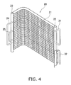
- FIG. 4 showing an exterior simplified perspective view of the outdoor heat exchanger 20
- FIG 5 showing a schematic rear view of the outdoor heat exchanger
- FIG. 6 which is a simplified rear view.
- the outdoor heat exchanger 20 is provided with a heat exchange part 21 where heat exchange takes place between outdoor air and the refrigerant, an outlet/inlet header collecting tube 22 disposed at a one end of this heat exchange part 21, and a doubled-back header collecting tube 23 disposed at the other end of this heat exchange part 21.
- FIG. 7 is a fragmentary enlarged cross sectional view of a cross sectional structure of the heat exchange part 21 of the outdoor heat exchanger 20, in a plane perpendicular to the direction of flattening of flat perforated tubes 21b thereof.
- FIG. 8 is a simplified perspective view of heat transfer fins 21a attached in the outdoor heat exchanger 20.
- the heat exchange part 21 has an upper-side heat exchange area X located at the upper side, and a lower-side heat exchange area Y located below the upper-side heat exchange area X.
- the upper-side heat exchange area X has a first upper-side heat exchange part X1, a second upper-side heat exchange part X2, and a third upper-side heat exchange part X3, arranged in that order from the top.
- the lower-side heat exchange area Y has a first lower-side heat exchange part Y1, and a second lower-side heat exchange part Y2, and a third lower-side heat exchange part Y3, arranged in that order from the top.
- This heat exchange part 21 is constituted by a multitude of the heat transfer fins 21a and a multitude of the flat perforated tubes 21b.
- the heat transfer fins 21a and the flat perforated tubes 21 b are both fabricated from aluminum or aluminum alloy.
- the heat transfer fins 21a are flat members, and a plurality of cutouts 21 aa extending in a horizontal direction for insertion of flattened tubes are formed side by side in a vertical direction in the heat transfer fins 21 a.
- the heat transfer fins 21 a are attached so as to have innumerable sections protruding towards the upstream side of the air flow.
- the flat perforated tubes 21b function as heat transfer tubes for transferring heat moving between the heat transfer fins 21 a and the outside air to the refrigerant flowing through the interior.
- the flat perforated tubes 21b have upper and lower flat surfaces serving as heat transfer surfaces, and a plurality of internal channels 21ba through which the refrigerant flows.
- the flat perforated tubes 21b which are slightly thicker in vertical breadth than the cutouts 21aa, are arrayed spaced apart in a plurality of tiers with the heat transfer surfaces facing up and down, and are temporarily fastened by being fitted into the cutouts 21aa.
- the heat transfer fins 21a and the flat perforated tubes 21b are brazed.
- the flat perforated tubes 21b are fitted at either end into the outlet/inlet header collecting tube 22 and the doubled-back header collecting tube 23, respectively, and brazed.
- the heat transfer fins 21 a link up on the vertical, and therefore any dew condensation occurring on the heat transfer fins 21 a and/or the flat perforated tubes 21b will drip down along the heat transfer fins 21a and drain to the outside through a path formed in the bottom panel 12.
- the outlet/inlet header collecting tube 22 is a cylindrical member made of aluminum or aluminum alloy, disposed at a one end of the heat exchange part 21, and extending in the vertical direction.
- the outlet/inlet header collecting tube 22 includes the upper outlet/inlet internal spaces 22a, 22b which are partitioned off in the vertical direction by a first baffle 22c.
- the gas refrigerant pipeline 31 is connected to the upper outlet/inlet internal space 22a in a top part, and the liquid refrigerant pipeline 32 is connected to the lower outlet/inlet internal space 22b in a bottom part.
- Both the upper outlet/inlet internal space 22a in the top part of the outlet/inlet header collecting tube 22 and the lower outlet/inlet internal space 22b in the bottom part are connected to one ends of the plurality of flat perforated tubes 21b. More specifically, the first upper-side heat exchange part X1, the second upper-side heat exchange part X2, and the third upper-side heat exchange part X3 of the upper-side heat exchange area X are disposed in such a way as to correspond to the upper outlet/inlet internal space 22a in the top part of the outlet/inlet header collecting tube 22.
- the first lower-side heat exchange part Y1, the second lower-side heat exchange part Y2, and the third lower-side heat exchange part Y3 of the lower-side heat exchange area Y are disposed in such a way as to correspond to the lower outlet/inlet internal space 22b in the bottom part of the outlet/inlet header collecting tube 22.
- the doubled-back header collecting tube 23 is a cylindrical member made of aluminum or aluminum alloy, disposed at the other end of the heat exchange part 21, and extending in the vertical direction.
- the interior of the doubled-back header collecting tube 23 is partitioned in the vertical direction by a second baffle 23g, a third baffle 23h, a third flow regulation plate 43, a fourth baffle 23i, and a fifth baffle 23j, forming the first to sixth internal spaces 23a, 23b, 23c, 23d, 23e, 23f.
- the three first to third internal spaces 23a, 23b, 23c of the doubled-back header collecting tube 23 are connected to the other ends of a multitude of the flat perforated tubes 21b which are connected at their one ends to the upper outlet/inlet internal space 22a at the top of the outlet/inlet header collecting tube 22.
- the first upper-side heat exchange part X1 of the upper-side heat exchange area X is disposed in such a way as to correspond to the first internal space 23a of the doubled-back header collecting tube 23, the second upper-side heat exchange part X2 of the upper-side heat exchange area X in such a way as to correspond to the second internal space 23b of the doubled-back header collecting tube 23, and the third upper-side heat exchange part X3 of the upper-side heat exchange area X in such a way as to correspond to the third internal space 23c of the doubled-back header collecting tube 23, respectively.
- the first lower-side heat exchange part Y1 of the lower-side heat exchange area Y is disposed in such a way as to correspond to the fourth internal space 23d of the doubled-back header collecting tube 23, the second lower-side heat exchange part Y2 of the lower-side heat exchange area Y in such a way as to correspond to the fifth internal space 23e of the doubled-back header collecting tube 23, and the third lower-side heat exchange part Y3 of the lower-side heat exchange area Y in such a way as to correspond to the sixth internal space 23f of the doubled-back header collecting tube 23, respectively.
- the first internal space 23a of the topmost tier and the internal space 23k of the bottommost tier of the doubled-back header collecting tube 23 are connected by an interconnecting pipeline 24.
- the second internal space 23b of the second tier from the top and the fifth internal space 23e of the second tier from the bottom are connected by an interconnecting pipeline 25.
- the third internal space 23c of the third tier from the top and the fourth internal space 23d of the third tier from the bottom are partitioned apart by the third flow regulation plate 43, but have sections that communicate vertically via a third inflow port 43x disposed in the third flow regulation plate 43.
- the design is such that the number of flat perforated tubes 21b into which refrigerant flowing in from the interconnecting pipeline 24 branches in the first internal space 23a of the doubled-back header collecting tube 23 is greater than the number of flat perforated tubes 21b into which the refrigerant flowing from the liquid refrigerant pipeline 32 branches in the lower outlet/inlet internal space 22b of the outlet/inlet header collecting tube 22 as the refrigerant advances to the sixth internal space 23f (the same holds for the relationship of the numbers of the flat perforated tubes 21b of the second internal space 23b and the fifth internal space 23e, and/or the relationship of the numbers of the flat perforated tubes 21b of the third internal space 23c and the fourth internal space 23d).
- the number of the flat perforated tubes 21b connected to the first internal space 23a, the number of the flat perforated tubes 21b connected to the second internal space 23b, and the number of the flat perforated tubes 21b connected to the third internal space 23c are substantially equal.
- the number of the flat perforated tubes 21b connected to the fourth internal space 23d, the number of the flat perforated tubes 21b connected to the fifth internal space 23e, and the number of the flat perforated tubes 21b connected to the sixth internal space 23f are substantially equal.
- the upper three first to third internal spaces 23a, 23b, 23c are furnished with a loop structure and with a flow regulating structure.
- the loop structure and a flow regulating structure of the first to third internal spaces 23a, 23b, 23c, respectively, are described below.
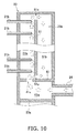
- the first internal space 23a uppermost in the doubled-back header collecting tube 23 is furnished with a first flow regulation plate 41 and a first partition plate 51.
- the first flow regulation plate 41 is a substantially disk-shaped plate member that partitions the first internal space 23 a into a first flow regulation space 41 a below, and a first outflow space 51a and loop structure 51b above.
- the first flow regulation space 41a is a space located above the second baffle 23g partitioning the first internal space 23a and the second internal space 23b, and below the first flow regulation plate 41 disposed at a location lower than the flat perforated tube 21b immediately above the second baffle 23 g.
- the interconnecting pipeline 24 extending out from the bottommost sixth space 23f of the doubled-back header collecting tube 23 communicates with this first flow regulation space 41a.
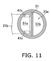
- the first partition plate 51 is a generally square plate member that partitions a space above the first flow regulation space 41a in the first internal space 23a into a first outflow space 51a and a first loop space 51b. While there are no particular limitations, the first partition plate 51 in the present embodiment is disposed at the center of the first internal space 23a to partition the space above the first flow regulation space 41a such that the first outflow space 51 a and the first loop space 51 b are equal in breadth in top view.
- the first partition plate 51 is fastened such that side surfaces thereof contact an inner peripheral surface of the doubled-back header collecting tube 23.
- the first outflow space 51 a is a space situated on the side at which the flat perforated tubes 21b connect at their one ends in the first internal space 23 a.
- the first loop space 51b is a space situated on the opposite side of the first partition plate 51 from the first outflow space 51a in the first internal space 23 a.
- a first upper communicating passage 51x constituted by a vertical gap between the inside of the top end of the doubled-back header collecting tube 23, and a top end section of the first partition plate 51.
- first lower communicating passage 51 y constituted by a vertical gap between the top surface of the first flow regulation plate 41 and a bottom end section of the first partition plate 51.
- first lower communicating passage 51y extends in a horizontal direction from the first loop space 51 b side towards the first outflow space 51a side.
- An outlet at the first outflow space 51a side of this first lower communicating passage 51y is located further below the location of the bottommost of the flat perforated tubes 21b connected to the first outflow space 51a.
- the first flow regulation plate 41 is furnished with two first inflow ports 41x; these are openings which are disposed in the first outflow space 51a constituting the space at the side at which the flat perforated tubes 21b extend in the first internal space 23a, and which provide communication in the vertical direction.
- the two inflow ports 41x are disposed away to the upstream side and the downstream side in the air flow direction, i.e., the direction of inflow of air with respect to the outdoor heat exchanger 20.
- the first inflow ports 41x are formed so as to be greater in width closer towards the first partition plate 51 side in the direction of air flow, and narrower in width closer towards the flat perforated tube 21b side in the direction of air flow.
- the first inflow ports 41x have shapes conforming to the inner peripheral surface of the doubled-back header collecting tube 23.
- the first internal space 23a has a flow regulation structure in which the refrigerant passage area (the area of a horizontal plane) in the first inflow ports 41x is sufficiently smaller than the refrigerant passage area of the first flow regulation space 41a (the area of the horizontal plane of the first flow regulation space 41a).
- the refrigerant flow going from the first flow regulation space 41 a towards the first outflow space 51a side can be sufficiently throttled, and the refrigerant flow velocity upwards in the vertical direction increased.
- the refrigerant passage area at the first outflow space 51a side (the passage area of the ascending refrigerant flow within the first outflow space 51a) can be made smaller than the total horizontal area of the first outflow space 51a and the first loop space 51b. In so doing, it is easy to maintain the ascension velocity of refrigerant inflowing to the first outflow space 51a via the first inflow ports 41 x, making it easy for the refrigerant to reach the upper section of the first outflow space 51a, even at a low circulation rate.
- the flat perforated tubes 21b are embedded within the first outflow space 51 a, in such a way as to fill in half or more of the horizontal area at heightwise locations in the first outflow space 51a where the flat perforated tubes 21b are absent.
- the flat perforated tubes 21b and the first inflow ports 41x of the first flow regulation plate 41 are arranged at partially overlapping locations in top view.
- this arrangement is such that when “the horizontal area of sections of flat perforated tubes 21b extending into the first outflow space 51a" is subtracted from “the horizontal area at heightwise locations within the first outflow space 51 a where no flat perforated tube 21b is present," the remaining area (the area of sections in which the refrigerant navigate around the flat perforated tubes 21b and ascend in the first outflow space 51a) is greater than the refrigerant passage area of the first lower communicating passage 51y.
- the first internal space 23a has a loop structure that includes the first inflow ports 41x, the first partition plate 51, the first upper communicating passage 51x, and the first lower communicating passage 51y. For this reason, as shown by arrows in FIG. 10 , refrigerant that reaches the top in the first outflow space 51a without inflowing to the flat perforated tubes 21 b is guided into the first loop space 51b via the first upper communicating passage 51x above the first partition plate 51, descends through gravity in the first loop space 51b, and returns to the bottom of the first outflow space 51 a via the first lower communicating passage 51y below the first partition plate 51. In so doing, it is possible for the refrigerant reaching the top of the first outflow space 51a to be looped around within the first internal space 23 a.
- the second internal space 23b which is second from the top of the doubled-back header collecting tube 23, is similar in configuration to the topmost first internal space 23a, and as shown in FIG. 6 , and in simplified cross sectional view in FIG. 12 , respectively, is furnished with a second flow regulation plate 42 and a second partition plate 52.
- the second flow regulation plate 42 is a generally disk-shaped plate member that partitions the second internal space 23b into a second flow regulation space 42a below, and a second outflow space 52a and second loop space 52b above.
- the second flow regulation space 42a is a space located above the third baffle 23h partitioning the second internal space 23b and the third internal space 23c, and below the second flow regulation plate 42 disposed at a location lower than the flat perforated tube 21b immediately above the third baffle 23h.
- the interconnecting pipeline 25 extending out from the fifth space 23e second from the bottom in the doubled-back header collecting tube 23 communicates with this second flow regulation space 42a.
- the second partition plate 52 is a generally square plate member that partitions a space above the second flow regulation plate 42a in the second internal space 23b into a second outflow space 52a and a second loop space 52b.
- the second outflow space 52a is a space situated on the side at which the flat perforated tubes 21b connect at their one ends, in the second internal space 23b.
- the second loop space 52b is a space situated on the opposite side of the second partition plate 52 from the second outflow space 52a side in the second internal space 23b.
- a second upper communicating passage 52x constituted by a vertical gap between the bottom surface of the second baffle 23g and a top end section of the second partition plate 52.
- a second lower communicating passage 52y constituted by a vertical gap between the top surface of the second flow regulation plate 42 and a bottom end section of the second partition plate 52.
- the second lower communicating passage 52y extends in a horizontal direction from the second loop space 52b side towards the second outflow space 52a side.
- An outlet at the second outflow space 52a side of this second lower communicating passage 52y is located further below the location of the bottommost of the flat perforated tubes 21b connected to the second outflow space 52a.
- the second flow regulation plate 42 is furnished with two second inflow ports 42x, which are vertically communicating openings disposed at the side from which the flat perforated tubes 21b extend in the second internal space 23b.
- the second internal space 23b has a flow regulation structure in which the refrigerant passage area (the area of a horizontal plane) in the second inflow ports 42x is sufficiently smaller than the refrigerant passage area of the second flow regulation space 42a (the area of the horizontal plane of the first flow regulation space 42a).
- the second internal space 23b has a loop structure that includes the second inflow ports 42x, the second partition plate 52, the second upper communicating passage 52x, and the second lower communicating passage 52y.
- the third internal space 23c which is third from the top of the doubled-back header collecting tube 23, is furnished with a third flow regulation plate 43 and a third partition plate 53, as shown in FIG. 6 , and in simplified cross sectional view in FIG. 13 , respectively.
- the third flow regulation plate 43 is a generally disk-shaped plate member that partitions the third internal space 23c into a fourth internal space 23d (space located below) that is third from the bottom of the doubled-back header collecting tube 23, and a third outflow space 53a and a third loop space 53b which are located above.
- the third partition plate 53 is a generally square plate member that partitions a space above the fourth internal space 23d in the third internal space 23c into a third outflow space 53a and a third loop space 53b.
- the third outflow space 53a is a space situated on the side at which the flat perforated tubes 21b connect at their one ends in the third internal space 23c.
- the third loop space 53b is a space situated on the opposite side of the third partition plate 53 from the third outflow space 53a in the third internal space 23c.
- a third upper communicating passage 53x constituted by a vertical gap between the bottom surface of the third baffle plate 23h and a top end section of the third partition plate 53.
- a third lower communicating passage 53y constituted by a vertical gap between the top surface of the third flow regulation plate 43 and a bottom end section of the third partition plate 53.
- the third lower communicating passage 53y extends in a horizontal direction from the third loop space 53b side towards the third outflow space 53a side.
- An outlet at the third outflow space 53a side of this third lower communicating passage 53y is located further below the location of the bottommost of the flat perforated tubes 21b connected to the third outflow space 53a.
- the third flow regulation plate 43 is furnished with two third inflow ports 43x, openings which are disposed at the side from which the flat perforated tubes 21b extend in the third internal space 23c, and which provide communication in the vertical direction.
- the third internal space 23c has a flow regulation structure in which the refrigerant passage area (the area of a horizontal plane) in the third inflow ports 43x is sufficiently smaller than the refrigerant passage area of the fourth internal space 23d (the area of the horizontal plane of the fourth internal space 23d).
- the third internal space 23c has a loop structure that includes the third inflow ports 43x, the third partition plate 53, the third upper communicating passage 53x, and the third lower communicating passage 53y.
- refrigerant in a gas-liquid two-phase state is supplied to the lower outlet/inlet internal space 22b of the outlet/inlet header collecting tube 22 via the liquid refrigerant pipeline 32.
- the state of the refrigerant inflowing to this lower outlet/inlet internal space 22b is assumed to be a gas-liquid two-phase state; however, depending on the outdoor temperature and/or the indoor temperature and/or the operational state, the inflowing refrigerant may be in a substantially single-phase liquid state.
- the refrigerant supplied to the lower outlet/inlet internal space 22b in the bottom part of the outlet/inlet header collecting tube 22 passes through the plurality of flat perforated tubes 21b in the bottom part of the heat exchange part 21 connected to the lower outlet/inlet internal space 22b, and is supplied respectively to the three fourth internal spaces 23d, 23e, 23f in the bottom part of the doubled-back header collecting tube 23.
- the refrigerant supplied to the sixth internal space 23f at the bottom of the doubled-back header collecting tube 23 passes through the interconnecting pipeline 24, and is supplied to the first internal space 23a in the top part of the doubled-back header collecting tube 23.
- the refrigerant supplied to the first internal space 23a inflows respectively to the plurality of flat perforated tubes 21b connected to the first internal space 23a (the flow of refrigerant within the first internal space 23a will be discussed below).
- the refrigerant flowing through the plurality of flat perforated tubes 21b further evaporates into a gas phase state, and is supplied to the upper outlet/inlet internal space 22a at the top of the outlet/inlet header collecting tube 22.
- the refrigerant supplied to the fifth internal space 23e in the bottom part of the doubled-back header collecting tube 23 passes through the interconnecting pipeline 25 and is supplied to the second internal space 23b in the top part of the doubled-back header collecting tube 23.
- the refrigerant supplied to the second internal space 23b inflows respectively to the plurality of flat perforated tubes 21b connected to the second internal space 23b (the flow of refrigerant within the second internal space 23b will be discussed below).
- the refrigerant flowing through the plurality of flat perforated tubes 21b further evaporates into a gas phase state, and is supplied to the upper outlet/inlet internal space 22a at the top of the outlet/inlet header collecting tube 22.
- the refrigerant supplied to the fourth internal space 23d in the bottom part of the doubled-back header collecting tube 23 passes upward on the vertical through the third inflow ports 43x furnished to the third flow regulation plate 43, and is supplied to the internal space of the third internal space 23c in the top part of the doubled-back header collecting tube 23.
- the refrigerant supplied to the third internal space 23c inflows respectively to the plurality of flat perforated tubes 21b connected to the third internal space 23c (the flow of refrigerant within the third internal space 23c will be discussed below).
- the refrigerant flowing through the plurality of flat perforated tubes 21b further evaporates into a gas phase state, and is supplied to the upper outlet/inlet internal space 22a at the top of the outlet/inlet header collecting tube 22.
- the refrigerant flow is the reverse of the flow indicated by arrows in FIG. 5 .
- the refrigerant inflowing to the lower outlet/inlet internal space 22b of the outlet/inlet header collecting tube 22 is depressurized in the expansion valve 33, and thereby enters a gas-liquid two-phase state.
- a portion of the liquid phase component in the refrigerant in the gas-liquid two-phase state that has flowed into to the first internal space 23a of the doubled-back header collecting tube 23 evaporates in the course of passage through the flat perforated tubes 21b from the lower outlet/inlet internal space 22b of the outlet/inlet header collecting tube 22 towards the sixth internal space 23f of the doubled-back header collecting tube 23.
- the refrigerant passing through the interconnecting pipeline 24 and flowing into the first internal space 23a of the doubled-back header collecting tube 23 is a mixture of a gas phase component and a liquid phase component that differ in specific gravity.
- the refrigerant flowing out from the other end side of these flat perforated tubes 21b does not easily reach superheat, and in some instances will reach the other end side of the flat perforated tubes 21b without evaporating, so that ultimately heat exchange capability cannot be sufficiently achieved.
- the refrigerant supplied to the first flow regulation space 41 a experiences an increase in the flow velocity of the vertical upward refrigerant flow as it passes through the first inflow ports 41x of the first flow regulation plate 41, which have a throttling function.
- the space above the first flow regulation plate 41 in the first internal space 23a is furnished with the first partition plate 51, the refrigerant passage area of the space on the side where the first inflow ports 41x are disposed (the first outflow space 51a) is constituted so as to be narrower as compared to the case where the first partition plate 51 is absent, and therefore the ascending flow velocity does not readily decline. For this reason, even in cases of a low circulation rate, the high-specific gravity liquid phase component in the refrigerant can be easily guided to the top within the first outflow space 51a.
- the flow is divided among the flat perforated tubes 21b, but a small portion of the refrigerant is guided to the top end of the first outflow space 51a without flowing into the flat perforated tubes 21 b.
- the refrigerant having reached the top end of the first outflow space 51 a in this manner is guided into the first loop space 51b via the first upper communicating passage 51x, and descends in the first loop space 51b through gravity.
- the refrigerant having descended through the first loop space 51b flows in a horizontal direction while passing through the first lower communicating passage 51y which extends in the horizontal direction, and again returns to the bottom of the first outflow space 51a.
- the refrigerant that has returned to the first outflow space 51a via the lower communicating passage 51 y is entrained by the ascending flow of the refrigerant passing through the first inflow ports 41 x and again ascends within the first outflow space 51 a, and according to circumstances can be made to inflow to the flat perforated tubes 21b after being recirculated through the first internal space 23 a.
- the second internal space 23b and the third internal space 23c of the doubled-back header collecting tube 23 function in the same way as the first internal space 23a, and therefore description is omitted.
- the state of the refrigerant inflowing to the first internal space 23a of the doubled-back header collecting tube 23 is one of admixture of a gas phase component and a liquid phase component differing in specific gravity.
- the amount of refrigerant inflowing per unit time into the first flow regulation space 41a via the interconnecting pipeline 24 is large, and the flow velocity of the refrigerant flowing from the outlet of the interconnecting pipeline 24 is relatively fast. Moreover, the flow velocity is increased even further by the adoption of the throttling function of the first inflow ports 41x as the low circulation flow countermeasure discussed previously. Further, due to the narrow refrigerant passage area of the first outflow space 51a, the refrigerant passage area of which is constricted by the first partition plate 51 as the low circulation flow countermeasure discussed previously, there is almost no letdown in the ascension velocity of the refrigerant.
- the high-specific gravity liquid phase component of the refrigerant passing forcefully through the first inflow ports 41x tends to pass through the first outflow space 51a without inflowing to the flat perforated tubes 21b, and tends to collect at the top.
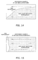
- the high-specific gravity liquid phase component tends to collect at the top while low-specific gravity gas phase component tends to collect at the bottom, and ultimately, eccentric flow arises as shown in the descriptive diagram of FIG. 16 , showing a reference example during a high circulation rate, although the distribution differs from that at times of a low circulation rate.
- the outdoor heat exchanger 20 of the present embodiment due to the adoption of the loop structure in the first internal space 23a, the refrigerant reaching the top end of the first outflow space 51a is guided into the first loop space 51 b via the first upper communicating passage 51x, and after descending through the first loop space 51b is again returned to the first outflow space 51a via the first lower communicating passage 51y, and thereby can be guided into the flat perforated tubes 21b located towards the bottom of the first outflow space 51a.
- the refrigerant returning to the first outflow space 51 a via the first lower communicating passage 51y is entrained by the ascending flow of refrigerant passing through the first inflow ports 41x and again ascends within the first outflow space 51a, and according to circumstances can be made to inflow to the flat perforated tubes 21b after being recirculated through the first internal space 23 a.
- the outdoor heat exchanger 20 of the present embodiment even at times of a high circulation rate, it is possible for the state of the refrigerant flowing into the plurality of flat perforated tubes 21b arranged at sections of different heights to be brought into approximation with the state depicted in the descriptive diagram of FIG. 15 , showing a reference example during a medium circulation rate, and to be rendered as uniform as possible.
- the second internal space 23b and the third internal space 23c of the doubled-back header collecting tube 23 function in the same way as the first internal space 23a, and therefore description is omitted.
- the ascent velocity of the refrigerant in the first inner space 23a of the doubled-back header collecting tube 23 is maintained by the first inflow ports 41x and by the configuration of the first outflow space 51a constricted by the first partition plate 51, so that the refrigerant can more easily reach the top of the first outflow space 51a (the design of the second internal space 23b and the third internal space 23c is the same).
- the outdoor heat exchanger 20 of the present embodiment even in cases of a high circulation rate, the refrigerant loops around within the first internal space 23a due to the loop structure adopted in the first internal space 23a of the doubled-back header collecting tube 23, whereby the refrigerant can be guided into the flat perforated tubes 21b.
- a loop structure and a flow regulating structure are adopted in the first to third internal spaces 23a, 23b, 23c of the doubled-back header collecting tube 23, but neither in the upper outlet/inlet internal spaces 22a, 22b of the outlet/inlet header collecting tube 22, nor in the fourth internal spaces 23d, 23e, 23f of the doubled-back header collecting tube 23.
- the loop structure and the flow regulating structure are adopted in the first to third internal spaces 23a, 23b, 23c of the doubled-back header collecting tube 23, in which the refrigerant flowing therethrough in heating mode contains large amounts of admixed gas phase and liquid phase components, resulting in a marked tendency for eccentric flow to arise among the flat perforated tubes 21b at different heights.
- the refrigerant which has passed through the first inflow ports 41x of the outdoor heat exchanger 20 of the present embodiment and just flowed into the first outflow space 51a is at maximum ascent velocity, and in some instances tends not to pass through the lower tubes among the plurality of flat perforated tubes 21 b connected to the first outflow space 51a.
- the outlet at the first outflow space 51a side of the first lower communicating passage 51 y is arranged such the refrigerant descending through the first loop space 51b in the first internal space 23a of the doubled-back header collecting tube 23 can be guided into the flat perforated tubes 21b that are connected to the bottom of the first outflow space 51a.
- the flat perforated tubes 21b that are located at the bottom, through which the high-flow velocity refrigerant inflowing to the first outflow space 51a via the first inflow ports 41x tends to pass, can be easily supplied with the refrigerant that has been returned to the first outflow space 51a via the first lower communicating passage 51 y.
- the present invention is not limited to this arrangement; another acceptable configuration would be one in which, for example, the first lower communicating passage 51y, rather than extending in the horizontal direction as in the aforedescribed embodiment, is instead inclined so as be located further towards the bottom going from the first loop space 51b side towards the first outflow space side 51a, or is inclined so as be located further towards the top going from the first loop space 51 b side towards the first outflow space side 51a.
- the extent of this incline an incline of 60 degrees or less with respect to the horizontal direction would be acceptable, as would one of 30 degrees or less; and an incline of -60 degrees or more with respect to the horizontal direction would be acceptable, as would one of -30 degrees or more, for example.
- the extent of the incline is preferably from 0 to 60 degrees, and more preferably 0 to 30 degrees, with respect to the horizontal direction.
- the first flow regulation plate 41 a plate-shaped member, is furnished with the first inflow ports 41x that open in the thickness direction (as do the second inflow ports 42x and the third inflow ports 43x).
- the present invention is not limited to this arrangement, and, for example, a cylindrical inflow passage extending in the vertical direction could be furnished in place of inflow ports formed by openings in a plate-shaped member. In this case, it will be possible to further boost the velocity of the refrigerant outflowing vertically upward as the refrigerant passes through the cylindrical inflow passage.
- the present invention is not limited to this arrangement, and the locations of the first inflow ports 41x in top view are arbitrary, provided that the locations are at the first outflow space 51a side, for example.
- the present invention is not limited to this arrangement; it would be acceptable for the outlet of the first lower communicating passage 51y at the first outflow space 51a side to be situated in proximity to the location of the bottommost of the plurality of flat perforated tubes 21 b connected to the first outflow space 51 a, for example, at the same height at the bottommost one.
- the doubled-back header collecting tube 23 has the first lower communicating passage 51 y which constituted by the lower end section of the first partition plate 51 and the top surface section of the first flow regulation plate 41 (the second lower communicating passage 52y and the third lower communicating passage 53y are similarly constituted).
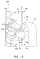
- the present invention is not limited to this arrangement; it would be acceptable to adopt, for example, a doubled-back header collecting tube 123 like that shown in FIG. 17 , in place of the doubled-back header collecting tube 23 of the aforedescribed embodiment.
- the doubled-back header collecting tube 123 is furnished with a first lower communicating passage 151y perforating the bottom of a first partition plate 151 in the thickness direction so as to connect the first outflow space 51a and the first loop space 51b.
- the entirety of the lower end section of the first partition plate 151 is supported through contact with the top surface of the first flow regulation plate 41.
- the first lower communicating passage 151y of the first partition plate 151 may be designed beforehand to have the desired refrigerant passage area, whereby manufacture can be simplified.
- the doubled-back header collecting tube 223 is constituted such that a portion of a lower end section of a first partition plate 251 is depressed upwardly. For this reason, with the first partition plate 251 positioned on the top surface of the first flow regulation plate 41, it is possible for a first lower communicating passage 251 y to be constituted by the top surface (flat surface) of the first flow regulation plate 41 and the upwardly depressed section of the lower end section of the first partition plate 251.
- the size of the depressed section of the lower end section of the second partition plate 251 may be designed beforehand to have the desired refrigerant passage area, whereby manufacture can be simplified.
- the second partition plate 251 it is possible for the second partition plate 251 to be supported by the non-depressed sections of the lower end section thereof arranged so as to contact the top surface of the first flow regulation plate 41.
- the present invention is not limited to this arrangement, and application, for example, to a heat exchanger employing corrugated type heat transfer fins, such as those employed primarily in automotive heat exchangers, would also be possible.
- Patent Literature 1 Japanese Laid-open Patent Application No. H02-219966
Landscapes
- Engineering & Computer Science (AREA)
- Physics & Mathematics (AREA)
- Mechanical Engineering (AREA)
- Thermal Sciences (AREA)
- General Engineering & Computer Science (AREA)
- Geometry (AREA)
- Heat-Exchange Devices With Radiators And Conduit Assemblies (AREA)
- Details Of Heat-Exchange And Heat-Transfer (AREA)
Abstract
Description
- The present invention relates to a heat exchanger and an air conditioning device.
- Heat exchangers of a design having a plurality of flat tubes, fins which are joined to the plurality of flat tubes, and header collecting tubes which are coupled respectively to the plurality of flat tubes at a one end side and another end side thereof, for bringing about heat exchange between a refrigerant flowing through the interior the flat tubes and air flowing to the outside of the flat tubes, are known in the prior art.
- For example, the heat exchanger disclosed in Patent Literature 1 (
Japanese Laid-open Patent No. 2-219966 - The heat exchanger disclosed in
Patent Literature 1 is directed to the problem that, in the interior of the header collecting tubes that extend in the vertical direction, liquid phase refrigerant of high specific gravity collects towards the bottom while gas phase refrigerant of low specific gravity collects towards the top, thereby giving rise to eccentric flow; in order to solve this problem, the feature of forming a throttle inside the header collecting tubes is proposed. - Passing the refrigerant through the throttle formed in this manner facilitates mixing of the gas phase refrigerant and the liquid phase refrigerant, while at the same time improves the flow velocity, making it easy for the refrigerant to reach the top within the header collecting tubes, thereby minimizing eccentric flow of the refrigerant.
- However, in a heat exchanger such as that disclosed in
Patent Literature 1 above, it has in no way been contemplated to minimize eccentric flow such as may occur under conditions in which the circulation rate of the refrigerant varies; and no consideration whatsoever has been given to a structure that would afford the effect of minimizing eccentric flow, both in cases of a low circulation rate and in cases of a high circulation rate. - Specifically, in the case of a low circulation rate, it is possible to increase the flow velocity by forming a throttle, causing the refrigerant to reach the top within the header collecting tube, thereby minimizing eccentric flow; in the case of a high circulation rate, however, the flow velocity becomes too high due to the throttle, and the liquid phase refrigerant of high specific gravity collects to an excessive extent towards the top, giving rise in some instances to eccentric flow.
- On the other hand, while, in cased of a high circulation rate, it is possible to minimize eccentric flow by providing a throttle that has been adjusted such that the flow velocity does not become too high, when the throttle is adjusted in this manner, in cases of a low circulation rate it may be difficult for the refrigerant to reach the top, giving rise in some instances to eccentric flow.
- With the foregoing in view, it is an object of the present invention to provide a heat exchanger and an air conditioning device, with which it is possible to minimize eccentric flow of the refrigerant, even when employed under conditions in which the circulation rate varies.
- The heat exchanger according to a first aspect of the present invention is provided with a plurality of flat tubes, a header collecting tube, and a plurality of fins. The plurality of flat tubes are arranged mutually. The header collecting tube has the one ends of the flat tubes connected thereto, and extends in a vertical direction. The plurality of fins are joined to the flat tubes. The header collecting tube has a loop structure. The loop structure includes partition members, inflow ports, upper communicating passages, and lower communicating passages. The partition members partition internal spaces into first spaces which are spaces to the side where the flat tubes are connected, and second spaces which are spaces to the side opposite from the side where the flat tubes are connected to the first space. The inflow ports are located in lower parts of the first spaces, and in the case of functioning as a refrigerant evaporator, prompt inflow of refrigerant so as to give rise to an ascending flow within the first spaces. The upper communicating passages are located in upper parts of the first spaces and the second spaces, and provide communication between the upper parts of the first spaces and the second spaces, thereby guiding the refrigerant which has ascended within the first spaces into the second spaces. The lower communicating passages are located in lower parts of the first spaces and the second spaces, provide communication between the lower parts of the first spaces and the second spaces, and by guiding the refrigerant in a direction other than vertical direction from the second spaces towards spaces above the inflow ports in the first spaces, guide the refrigerant from the first spaces to the second spaces, and return the refrigerant having descended through the second spaces from the second spaces to the first spaces. Herein, "inlet port" is used to include not only openings that are furnished to thin plate-shaped members, but where inflow passages formed to passage shape are provided, the outlets thereof as well. The "direction other than vertical direction" herein is not particularly limited provided that the direction is one leading from the second spaces to spaces above the inflow ports in the first spaces, and may include, for example, a horizontal direction leading from the second space side towards the first space side; a direction inclined towards the first space side from the second space side would also be acceptable. An incline of 60 degrees or less with respect to the horizontal direction would be an acceptable incline, as would one of 30 degrees or less; and an incline of -60 degrees or more with respect to the horizontal direction would be acceptable, as would one of -30 degrees or more.
- With this heat exchanger, the internal spaces of the header collecting tube are partitioned by the partition members into the first spaces and the second spaces, whereby the area through which the refrigerant having flowed into the first spaces from the inflow ports passes while ascending through the first spaces can be made smaller, as compared with the case in which the first spaces and the second spaces are not partitioned by partition members. For this reason, even when the circulation rate of the refrigerant is a low circulation rate, the refrigerant having flowed into the first spaces from the inflow ports can be made to ascend through the narrow spaces of the first spaces only, whereby the refrigerant can easily reach the upper parts of the internal spaces of the header collecting tubes without experiencing any significant drop in the velocity of ascension of the refrigerant through the first spaces. For this reason, even when the circulation rate of the refrigerant is a low circulation rate, sufficient flow of the refrigerant to the flat tubes arranged towards the top is possible.
- Moreover, in this heat exchanger, the header collecting tube has a loop structure that includes the inflow ports, the partition members, the upper communication passages, and the lower communication passages. For this reason, even when the flow velocity of the refrigerant inflowing to the first spaces from the inflow ports is fast, such as may be encountered at high circulation rates, and the high-specific gravity refrigerant passes forcefully while traversing the flat tubes located towards the bottom leading to a tendency to collect in upper parts of the first spaces, it is possible for the high-specific gravity refrigerant having reached upper sections of the first spaces to be returned back to the lower parts of the first spaces by means of the loop structure. Specifically, with this loop structure, it is possible for the refrigerant having reached upper sections of the first spaces to pass through the upper communicating passages and be fed to the second space side, and to then descend through the second spaces and flow through the lower communicating passages into lower parts of the first spaces, and thereby guided into the flat tubes that are present at the lower parts of the first spaces. For this reason, even when the flow velocity of the refrigerant inflowing to the first spaces is fast, such as may be encountered at high circulation rates, and the high-specific gravity refrigerant passes forcefully while traversing the flat tubes located towards the bottom leading to a tendency to collect in upper parts of the first spaces, sufficient flow of the refrigerant to the flat tubes at the bottom is possible.
- In so doing, it is possible to keep eccentric flow of the refrigerant to flat tubes located at different heights to be kept to a minimum, even at times of a high circulation rate or at times of a low circulation rate.
- A heat exchanger according to a second aspect of the present invention is the heat exchanger according to the first aspect of the present invention, wherein the lower communicating passages are disposed above the inflow ports, near the bottommost flat tubes above the inflow ports. The bottommost flat tubes above the inflow ports are those that are situated at bottommost locations among the flat tubes located above the inflow ports. Provided that the lower communicating passages of this heat exchanger are located above the inflow ports and near the bottommost flat tubes above the inflow ports, the passages may be disposed above the inflow ports at locations at the same height as the bottommost flat tubes above the inflow ports, or at places therebelow. It is also acceptable for only the outlets of the lower communicating passages to be located above the inflow port and near the bottommost flat tubes above the inflow ports.
- With this heat exchanger, in cases in which the flow velocity of the refrigerant passing through the inflow ports is fast, such as is encountered in cases of a high circulation rate, in some instances the particularly high-velocity refrigerant having just passed through the inflow ports passes forcefully through the bottommost flat tubes above the inflow ports, which of those above the inflow ports are located furthest to the bottom, making inflow to the bottommost flat tubes above the inflow ports difficult. With this heat exchanger, however, even in such cases, the refrigerant having passed forcefully through the inflow ports is guided into the second spaces via the upper communicating passages in the upper parts of the first spaces, and after descending through the second spaces, passes through the lower communicating passages and towards the lower parts of the first spaces, making it possible to be sufficiently guided into the bottommost flat tubes above the inflow ports.
- A heat exchanger according to a third aspect of the present invention is the heat exchanger according to the first or second aspect of the present invention, wherein flow regulation spaces are formed at the bottoms of the first spaces and second spaces among the internal spaces. The first and second spaces and the flow regulation spaces are partitioned by flow regulation members. The inflow ports are furnished to the flow regulation members, in such a way that the passage cross section area of the refrigerant going from the flow regulation spaces towards the first spaces can be throttled.
- With this heat exchanger, the refrigerant flowing from the flow regulation spaces below to the first spaces above can be passed through the inflow ports which are disposed so as to throttle the passage cross section area. In so doing, the flow velocity of the flow of refrigerant passing from the flow regulation spaces to the first spaces through the inflow ports can be increased, and an ascending flow of the refrigerant through the first spaces can be easily produced. Additionally, because the first spaces, the second spaces, and the flow regulation spaces are disposed within the header collecting tube, there is no need to provide any arrangement, other than the header collecting tube, in order to produce an ascending flow of the refrigerant through the first spaces.
- A heat exchanger according to a fourth aspect of the present invention is the heat exchanger according to the third aspect of the present invention, wherein the lower communicating passages are constituted by lower sections of the partition members and upper sections of the flow regulation members.
- With this heat exchanger, because the lower communicating passages are constituted by lower sections of the partition members and upper sections of the flow regulation members, even if liquid phase refrigerant collects in the second spaces, the liquid phase refrigerant is caused to flow, due to gravity, towards the first space side along the upper sections of the flow regulation members and pass through the lower communicating passages, thereby making it possible to easily return to the first spaces.
- A heat exchanger according to a fifth aspect of the present invention is the heat exchanger according to the any of the first to fourth aspects of the present invention, wherein the loop structure is arranged at locations such that, when a function as an evaporator for the refrigerant is performed, it is possible for the refrigerant, after having passed through a portion of the plurality of flat tubes, to flow in distributed fashion to another portion of the plurality of flat tubes.
- With this heat exchanger, when a function as an evaporator for the refrigerant is performed, part of the refrigerant evaporates during passage through part of the plurality of flat tubes. For this reason, the refrigerant, after having passed through part of the plurality of flat tubes, is a mixture of a gas phase component and a liquid phase component. Unlike cases involving the gas phase only or the liquid phase only, when refrigerant containing such a mixture of a gas phase component and a liquid phase component differing in specific gravity passes through a header collecting tube of a heat exchanger of conventional construction, when the flow velocity is low, the liquid phase component tends to collect below and the gas phase component tends to collect above, whereas when the flow velocity is high, the liquid phase component tends to collect above and the gas phase component tends to collect below, making eccentric flow among the plurality of flat tubes arranged at different heights particularly prone to occur.
- In contrast, with this heat exchanger, the loop structure is arranged at a location such that refrigerant containing a mixture of a gas phase component and a liquid phase component differing in specific gravity experiences further flow in distributed fashion to another part of the plurality of flat tubes, whereby it is possible to effectively minimize eccentric flow of the refrigerant flows.
- A heat exchanger according to a sixth aspect of the present invention is the heat exchanger according to the fifth aspect of the present invention, wherein the plurality of flat tubes are connected at one ends thereof to a doubled-back header collecting tube that includes the header collecting tube and doubles back the refrigerant flow, and at the other ends are connected to a facing header collecting tube arranged facing the doubled-back header collecting tube. The plurality of flat tubes are grouped into an upper-side heat exchange area, and a lower-side heat exchange area located below the upper-side heat exchange area. The upper-side heat exchange area is constituted by one or plurality of upper-side heat exchange parts arrayed. The lower-side heat exchange area is constituted by one or plurality of lower-side heat exchange parts vertically arrayed. A facing lower-side internal space, corresponding to the lower-side heat exchange parts constituting the lower-side heat exchange area, is formed at the lower-side of the interior of the facing header collecting tube.
- The interior of the doubled-back header collecting tube is partitioned on the vertical into doubled-back upper-side internal spaces and doubled-back lower-side internal spaces. The doubled-back upper-side internal spaces correspond in number to the number of the upper-side heat exchange parts constituting the upper-side heat exchange area. The doubled-back lower-side internal spaces correspond in number to the number of lower-side heat exchange parts constituting the lower-side heat exchange area. The doubled-back upper-side internal spaces and the doubled-back lower-side internal spaces communicate with one another. The loop structure is arranged in the doubled-back upper-side internal spaces.
- With this heat exchanger, because a loop structure is arranged in the doubled-back upper-side internal spaces, it is possible for eccentric flowing of a gas-liquid two-phase refrigerant that contains a gas phase component having evaporated in the course of passage through the lower-side heat exchange area, and that is fed from the doubled-back lower-side internal spaces to the doubled-back upper-side internal spaces, to be effectively minimized when the refrigerant flows towards the upper-side heat exchange parts.
- An air conditioning device according to a seventh aspect of the present invention is provided with a refrigerant circuit. The refrigerant circuit is constituted by connecting the heat exchanger according to any of the first to sixth aspects of the present invention, and a variable-capacity compressor.
- With this air conditioning device, driving by the variable-capacity compressor causes the rate at which the refrigerant flowing circulates through the refrigerant circuit to fluctuate, and the amount of refrigerant passing through the heat exchanger to fluctuate. In cases in which the heat exchanger functions as an evaporator, it will be possible to keep eccentric flow of the refrigerant within the heat exchanger to a minimum, even when the amount of the refrigerant passing therethrough increases and the mixture ratio of liquid phase refrigerant increases, or the flow velocity increases.
- With the heat exchanger according to the first aspect of the present invention, it is possible minimize eccentric flow of the refrigerant to flat tubes located at different heights, both during times of a low circulation rate and times of a high circulation rate.
- With the heat exchanger according to the second aspect of the present invention, it is possible for the refrigerant to be sufficiently guided to the bottommost flat tubes above the inflow ports.
- With the heat exchanger according to the third aspect of the present invention, an ascending flow of refrigerant in the first spaces is easily produced by the header collecting tube alone.
- With the heat exchanger according to the fourth aspect of the present invention, it is possible for liquid phase refrigerant collecting in the second spaces to be easily returned to the first spaces.
- With the heat exchanger according to the fifth aspect of the present invention, it is possible to effectively minimize eccentric flow of the refrigerant flow.
- With the heat exchanger according to the sixth aspect of the present invention, it is possible to effectively minimize eccentric flow of the refrigerant flow as a gas-liquid two-phase refrigerant in the first upper-side internal spaces flows towards the upper-side heat exchange parts.
- With the air conditioning device according to the seventh aspect of the present invention, in cases in which the heat exchanger functions as an evaporator, it is possible to keep eccentric flow of the refrigerant within the heat exchanger to a minimum, even when the amount of the refrigerant passing therethrough increases and the mixture ratio of liquid phase refrigerant increases, or the flow velocity increases.
-
-
FIG. 1 is a circuit diagram of overview of the scheme of an air conditioning device according to an embodiment; -
FIG. 2 is a perspective view of the exterior of an air conditioning outdoor unit; -
FIG. 3 is a schematic cross sectional view of an overview of placement of machinery of an air conditioning outdoor unit; -
FIG. 4 is an exterior simplified perspective view of an outdoor heat exchanger, a gas refrigerant pipeline, and a liquid refrigerant pipeline; -
FIG. 5 is a schematic rear view of a simplified configuration of an outdoor heat exchanger; -
FIG. 6 is a simplified rear view of a configuration of an outdoor heat exchanger; -
FIG. 7 is a fragmentary enlarged cross sectional view of a configuration of a heat exchange part of an outdoor heat exchanger; -
FIG. 8 is a simplified perspective view of heat transfer fins attached to an outdoor heat exchanger; -
FIG. 9 is a simplified configuration perspective view of a section near the top of a doubled-back header collecting tube; -
FIG. 10 is a simplified cross sectional view of the vicinity of a first internal space of a doubled-back header collecting tube; -
FIG. 11 is a simplified top view of the vicinity of a first internal space of a doubled-back header collecting tube; -
FIG. 12 is a simplified cross sectional view of the vicinity of a second internal space of a doubled-back header collecting tube; -
FIG. 13 is a simplified cross sectional view of the vicinity of a third internal space of a doubled-back header collecting tube; -
FIG. 14 is a descriptive diagram for reference purposes, showing a condition of refrigerant distribution at a low circulation rate; -
FIG. 15 is a descriptive diagram for reference purposes, showing a condition of refrigerant distribution at a medium circulation rate; -
FIG. 16 is a descriptive diagram for reference purposes, showing a condition of refrigerant distribution at a high circulation rate; -
FIG. 17 is a simplified configuration perspective view of a section near the top of a doubled-back header collecting tube according to another embodiment F; and -
FIG. 18 is a simplified configuration perspective view of a section near the top of a doubled-back header collecting tube according to another embodiment G. -
FIG. 1 is a circuit diagram describing an overview of a configuration of anair conditioning device 1 according to an embodiment of the present invention. - This
air conditioning device 1 is a device used for cooling and heating, through vapor compression refrigerating cycle operation, of a building interior in which an air conditioning indoor unit 3 has been installed, and is constituted by an air conditioningoutdoor unit 2 as a heat source-side unit and the air conditioning indoor unit 3 as a user-side unit, which are connected by refrigerant interconnectingpipelines 6, 7. - The refrigerant circuit constituted by connection of the air conditioning
outdoor unit 2, the air conditioning indoor unit 3, and therefrigerant interconnecting pipelines 6, 7 is further constituted by connecting acompressor 91, a four-way switching valve 92, anoutdoor heat exchanger 20, anexpansion valve 33, anindoor heat exchanger 4, anaccumulator 93, and the like, through refrigerant pipelines. A refrigerant is sealed within this refrigerant circuit, and refrigerating cycle operation involving compression, cooling, depressurization, and heating/evaporation of the refrigerant, followed by re-compression, is carried out. As the refrigerant, there may be employed one selected, for example, from R410A, R32, R407C, R22, R134a, carbon dioxide, and the like. - The air conditioning indoor unit 3 is installed by being wall-mounted on an indoor wall or the like, or by being recessed within or suspended from an indoor ceiling of a building or the like. The air conditioning indoor unit 3 includes the
indoor heat exchanger 4 and anindoor fan 5. Theindoor heat exchanger 4 is, for example, a fin-and-tube heat exchanger of cross fin type, constituted by a heat transfer tube and a multitude of fins. In cooling mode, the heat exchanger functions as an evaporator for the refrigerant to cool the indoor air, and in heating mode functions as a condenser for the refrigerant to heat the indoor air. - The air conditioning
outdoor unit 2 is installed outside a building or the like, and is connected to the air conditioning indoor unit 3 by therefrigerant interconnecting pipelines 6, 7. As shown inFIG. 2 andFIG. 3 , the air conditioningoutdoor unit 2 has aunit casing 10 of substantially cuboid shape. - As shown in
FIG. 3 , the air conditioningoutdoor unit 2 has a structure (a "trunk" type structure) in which a blower chamber S1 and a machinery chamber S2 are formed by dividing an internal space of theunit casing 10 into two by apartition panel 18 that extends in a vertical direction. The air conditioningoutdoor unit 2 includes anoutdoor heat exchanger 20 and anoutdoor fan 95 which are arranged within the blower chamber S1 of theunit casing 10, and also includes thecompressor 91, the four-way switching valve 92, theaccumulator 93, theexpansion valve 33, agas refrigerant pipeline 31, and a liquidrefrigerant pipeline 32 which are arranged within the machinery chamber S2 of theunit casing 10. - The
unit casing 10 constitutes a chassis and is provided with abottom panel 12, atop panel 11, aside panel 13 at the blower chamber side, aside panel 14 at the machinery chamber side, a blower chamber-side front panel 15, and a machinery chamber-side front panel 16. - The air conditioning
outdoor unit 2 is configured in such a way that outdoor air is sucked into the blower chamber S1 within the unit casing 10 from parts of the rear surface and the side surface of theunit casing 10, and the sucked outdoor air is vented from the front surface of theunit casing 10. In specific terms, anintake port 10a and anintake port 10b facing the blower chamber S1 within theunit casing 10 are formed between the rear face-side end of theside panel 13 at the blower chamber side and the blower chamber S1-side end of theside panel 14 at the machinery chamber side. The blower chamber-side front panel 15 is furnished with avent 10c, the front side thereof being covered by afan grill 15a. - The
compressor 91 is, for example, a sealed compressor driven by a compressor motor, and is configured such that the operating capacity can be varied through inverter control. - The four-
way switching valve 92 is a mechanism for switching the direction of flow of the refrigerant. In cooling mode, the four-way switching valve 92 connects a refrigerant pipeline which extends from the discharge side of thecompressor 91 and thegas refrigerant pipeline 31 which extends from a one end (the gas-side end) of theoutdoor heat exchanger 20, as well as connecting, via theaccumulator 93, the refrigerant interconnecting pipeline 7 for the gas refrigerant and the refrigerant pipeline at the intake side of the compressor 91 (see the solid lines of the four-way switching valve 92 inFIG. 1 ). In heating mode, the four-way switching valve 92 connects the refrigerant pipeline which extends from the discharge side of thecompressor 91 and the refrigerant interconnecting pipeline 7 for the gas refrigerant, as well as connecting, via theaccumulator 93, the intake side of thecompressor 91 and thegas refrigerant pipeline 31 which extends from the one end (the gas-side end) of the outdoor heat exchanger 20 (see the broken lines of the four-way switching valve 92 inFIG. 1 ). - The
outdoor heat exchanger 20 is arranged upright in a vertical direction in the blower chamber S1, and faces theintake ports outdoor heat exchanger 20 is a heat exchanger made of aluminum; in the present embodiment, one having design pressure of about 3-4 MPa is employed. Thegas refrigerant pipeline 31 extends from the one end (the gas-side end) of theoutdoor heat exchanger 20, so as to connect to the four-way switching valve 92. The liquidrefrigerant pipeline 32 extends from the other end (the liquid-side end) of theoutdoor heat exchanger 20, so as to connect to theexpansion valve 33. - The
accumulator 93 is connected between the four-way switching valve 92 and thecompressor 91. Theaccumulator 93 is equipped with a gas-liquid separation function for separating the refrigerant into a gas phase and a liquid phase. Refrigerant inflowing to theaccumulator 93 is separated into the gas phase and the liquid phase, and the gas phase refrigerant which collects in the upper spaces is supplied to thecompressor 91. - The
outdoor fan 95 supplies theoutdoor heat exchanger 20 with outdoor air for heat exchange with the refrigerant flowing through theoutdoor heat exchanger 20. - The
expansion valve 33 is a mechanism for depressurizing the refrigerant in the refrigerant circuit, and is an electrically-operated valve, the valve opening of which is adjustable. In order to make adjustments to the refrigerant pressure and the refrigerant flow rate, theexpansion valve 33 is disposed between theoutdoor heat exchanger 20 and therefrigerant interconnecting pipeline 6 for the liquid refrigerant, and has the function of expanding the refrigerant, both in cooling mode and heating mode. - The
outdoor fan 95 is arranged facing theoutdoor heat exchanger 20 in the blower chamber S1. Theoutdoor fan 95 sucks outdoor air into the unit, and after heat exchange between the outdoor air and the refrigerant has taken place in theoutdoor heat exchanger 20, discharges the heat-exchanged air to the outdoors. Thisoutdoor fan 95 is a fan in which it is possible to adjust the air volume of the air supplied to theoutdoor heat exchanger 20, and could be, for example, a propeller fan driven by a motor, such as a DC fan motor, or the like. - In cooling mode, the four-
way switching valve 92 enters the state shown by the solid lines inFIG 1 , i.e., a state in which the discharge side of thecompressor 91 is connected to the gas side of theoutdoor heat exchanger 20 via thegas refrigerant pipeline 31, and the intake side of thecompressor 91 is connected to the gas side of theindoor heat exchanger 4 via theaccumulator 93 and the refrigerant interconnecting pipeline 7. The design of theexpansion valve 33 is such that valve opening adjustments are made to maintain a constant degree of superheat (degree of superheat control) of the refrigerant at the outlet of the indoor heat exchanger 4 (i.e., the gas side of the indoor heat exchanger 4). With the refrigerant circuit in this state, when thecompressor 91, theoutdoor fan 95, and theindoor fan 5 are run, low-pressure gas refrigerant is compressed by thecompressor 91 to become high-pressure gas refrigerant. This high-pressure gas refrigerant is fed to theoutdoor heat exchanger 20 through the four-way switching valve 92. Subsequently, the high-pressure gas refrigerant undergoes heat exchange in theoutdoor heat exchanger 20 with outdoor air supplied by theoutdoor fan 95, and is condensed to become high-pressure liquid refrigerant. The high-pressure liquid refrigerant, now in a supercooled state, is fed to theexpansion valve 33 from theoutdoor heat exchanger 20. Refrigerant having been depressurized to close to the intake pressure of thecompressor 91 by theexpansion valve 33 and entered a low-pressure, gas-liquid two-phase state is fed to theindoor heat exchanger 4, and undergoes heat exchange with indoor air in theindoor heat exchanger 4, evaporating to become low-pressure gas refrigerant. - This low-pressure gas refrigerant is fed to the air conditioning
outdoor unit 2 through the refrigerant interconnecting pipeline 7, and is again sucked into thecompressor 91. In this cooling mode, theair conditioning device 1 prompts theoutdoor heat exchanger 20 to function as a condenser for the refrigerant compressed in thecompressor 91, and theindoor heat exchanger 4 to function as an evaporator for the refrigerant condensed in theoutdoor heat exchanger 20. - In the refrigerant circuit during cooling mode, while degree of superheat control by the
expansion valve 33 is taking place, thecompressor 91 is inverter-controlled to a set temperature (such that the cooling load can be processed), and therefore the circulation rate of the refrigerant may be a high circulation rate in some cases, and a low circulation rate in others. - In heating mode, the four-
way switching valve 92 enters the state shown by broken lines inFIG. 1 , i.e., a state in which the discharge side of thecompressor 91 is connected to the gas side of theindoor heat exchanger 4 via the refrigerant interconnecting pipeline 7, and the intake side of thecompressor 91 is connected to the gas side of theoutdoor heat exchanger 20 via thegas refrigerant pipeline 31. The design of theexpansion valve 33 is such that valve opening adjustments are made to maintain the degree of supercooling of the refrigerant at the outlet of theindoor heat exchanger 4 at a target degree of supercooling value (degree of supercooling control). With the refrigerant circuit in this state, when thecompressor 91, theoutdoor fan 95, and theindoor fan 5 are run, low-pressure gas refrigerant is sucked into and compressed by thecompressor 91 to become high-pressure gas refrigerant, and is fed to the air conditioning indoor unit 3 through the four-way switching valve 92 and the refrigerant interconnecting pipeline 7. - The high-pressure gas refrigerant fed to the air conditioning indoor unit 3 then undergoes heat exchange with indoor air in the
indoor heat exchanger 4, and is condensed to become high-pressure liquid refrigerant, then while passing through theexpansion valve 33 is depressurized to an extent commensurate with the valve opening of theexpansion valve 33. The refrigerant having passed through theexpansion valve 33 flows into theoutdoor heat exchanger 20. The refrigerant in a low-pressure, gas-liquid two-phase state having flowed into theoutdoor heat exchanger 20 undergoes heat exchange with outdoor air supplied by theoutdoor fan 95, evaporates to become low-pressure gas refrigerant, and is again sucked into thecompressor 91 through the four-way switching valve 92. In this heating mode, theair conditioning device 1 prompts theindoor heat exchanger 4 to function as a condenser for the refrigerant compressed in thecompressor 91, and theoutdoor heat exchanger 20 to function as an evaporator for the refrigerant condensed in theindoor heat exchanger 4. - In the refrigerant circuit during heating mode, while degree of supercooling control by the
expansion valve 33 is taking place, thecompressor 91 is inverter-controlled to a set temperature (such that the heating load can be processed), and therefore the circulation rate of the refrigerant may be a high circulation rate in some cases, and a low circulation rate in others. - Next, the configuration of the
outdoor heat exchanger 20 will be described usingFIG. 4 showing an exterior simplified perspective view of theoutdoor heat exchanger 20,FIG 5 showing a schematic rear view of the outdoor heat exchanger, andFIG. 6 which is a simplified rear view. - The
outdoor heat exchanger 20 is provided with aheat exchange part 21 where heat exchange takes place between outdoor air and the refrigerant, an outlet/inletheader collecting tube 22 disposed at a one end of thisheat exchange part 21, and a doubled-backheader collecting tube 23 disposed at the other end of thisheat exchange part 21. -
FIG. 7 is a fragmentary enlarged cross sectional view of a cross sectional structure of theheat exchange part 21 of theoutdoor heat exchanger 20, in a plane perpendicular to the direction of flattening of flatperforated tubes 21b thereof.FIG. 8 is a simplified perspective view ofheat transfer fins 21a attached in theoutdoor heat exchanger 20. - The
heat exchange part 21 has an upper-side heat exchange area X located at the upper side, and a lower-side heat exchange area Y located below the upper-side heat exchange area X. Among these, the upper-side heat exchange area X has a first upper-side heat exchange part X1, a second upper-side heat exchange part X2, and a third upper-side heat exchange part X3, arranged in that order from the top. The lower-side heat exchange area Y has a first lower-side heat exchange part Y1, and a second lower-side heat exchange part Y2, and a third lower-side heat exchange part Y3, arranged in that order from the top. - This
heat exchange part 21 is constituted by a multitude of theheat transfer fins 21a and a multitude of the flatperforated tubes 21b. Theheat transfer fins 21a and the flatperforated tubes 21 b are both fabricated from aluminum or aluminum alloy. - The
heat transfer fins 21a are flat members, and a plurality ofcutouts 21 aa extending in a horizontal direction for insertion of flattened tubes are formed side by side in a vertical direction in theheat transfer fins 21 a. Theheat transfer fins 21 a are attached so as to have innumerable sections protruding towards the upstream side of the air flow. - The flat
perforated tubes 21b function as heat transfer tubes for transferring heat moving between theheat transfer fins 21 a and the outside air to the refrigerant flowing through the interior. The flatperforated tubes 21b have upper and lower flat surfaces serving as heat transfer surfaces, and a plurality of internal channels 21ba through which the refrigerant flows. The flatperforated tubes 21b, which are slightly thicker in vertical breadth than the cutouts 21aa, are arrayed spaced apart in a plurality of tiers with the heat transfer surfaces facing up and down, and are temporarily fastened by being fitted into the cutouts 21aa. With the flatperforated tubes 21b temporarily fastened by being fitted into thecutouts 21 aa of theheat transfer fins 21a in this manner, theheat transfer fins 21a and the flatperforated tubes 21b are brazed. The flatperforated tubes 21b are fitted at either end into the outlet/inletheader collecting tube 22 and the doubled-backheader collecting tube 23, respectively, and brazed. In so doing, an upper outlet/inletinternal space 22a and a lower outlet/inletinternal space 22b in the outlet/inletheader collecting tube 22, discussed below, and/or first to sixthinternal spaces header collecting tube 23, and internal flow channels 21ba of the flatperforated tubes 21b, discussed below, are linked. - As shown in
FIG. 7 , theheat transfer fins 21 a link up on the vertical, and therefore any dew condensation occurring on theheat transfer fins 21 a and/or the flatperforated tubes 21b will drip down along theheat transfer fins 21a and drain to the outside through a path formed in thebottom panel 12. - The outlet/inlet
header collecting tube 22 is a cylindrical member made of aluminum or aluminum alloy, disposed at a one end of theheat exchange part 21, and extending in the vertical direction. - The outlet/inlet
header collecting tube 22 includes the upper outlet/inletinternal spaces first baffle 22c. Thegas refrigerant pipeline 31 is connected to the upper outlet/inletinternal space 22a in a top part, and the liquidrefrigerant pipeline 32 is connected to the lower outlet/inletinternal space 22b in a bottom part. - Both the upper outlet/inlet
internal space 22a in the top part of the outlet/inletheader collecting tube 22 and the lower outlet/inletinternal space 22b in the bottom part are connected to one ends of the plurality of flatperforated tubes 21b. More specifically, the first upper-side heat exchange part X1, the second upper-side heat exchange part X2, and the third upper-side heat exchange part X3 of the upper-side heat exchange area X are disposed in such a way as to correspond to the upper outlet/inletinternal space 22a in the top part of the outlet/inletheader collecting tube 22. The first lower-side heat exchange part Y1, the second lower-side heat exchange part Y2, and the third lower-side heat exchange part Y3 of the lower-side heat exchange area Y are disposed in such a way as to correspond to the lower outlet/inletinternal space 22b in the bottom part of the outlet/inletheader collecting tube 22. - The doubled-back
header collecting tube 23 is a cylindrical member made of aluminum or aluminum alloy, disposed at the other end of theheat exchange part 21, and extending in the vertical direction. - The interior of the doubled-back
header collecting tube 23 is partitioned in the vertical direction by asecond baffle 23g, athird baffle 23h, a thirdflow regulation plate 43, afourth baffle 23i, and afifth baffle 23j, forming the first to sixthinternal spaces - Of these, the three first to third
internal spaces header collecting tube 23 are connected to the other ends of a multitude of the flatperforated tubes 21b which are connected at their one ends to the upper outlet/inletinternal space 22a at the top of the outlet/inletheader collecting tube 22. Specifically, the first upper-side heat exchange part X1 of the upper-side heat exchange area X is disposed in such a way as to correspond to the firstinternal space 23a of the doubled-backheader collecting tube 23, the second upper-side heat exchange part X2 of the upper-side heat exchange area X in such a way as to correspond to the secondinternal space 23b of the doubled-backheader collecting tube 23, and the third upper-side heat exchange part X3 of the upper-side heat exchange area X in such a way as to correspond to the thirdinternal space 23c of the doubled-backheader collecting tube 23, respectively. - The multitude of flat
perforated tubes 21b connected at their one ends to the lower outlet/inletinternal space 22b in the bottom part of the outlet/inletheader collecting tube 22 connect at their other ends to the three fourthinternal spaces header collecting tube 23. Specifically, the first lower-side heat exchange part Y1 of the lower-side heat exchange area Y is disposed in such a way as to correspond to the fourthinternal space 23d of the doubled-backheader collecting tube 23, the second lower-side heat exchange part Y2 of the lower-side heat exchange area Y in such a way as to correspond to the fifthinternal space 23e of the doubled-backheader collecting tube 23, and the third lower-side heat exchange part Y3 of the lower-side heat exchange area Y in such a way as to correspond to the sixthinternal space 23f of the doubled-backheader collecting tube 23, respectively. - The first
internal space 23a of the topmost tier and the internal space 23k of the bottommost tier of the doubled-backheader collecting tube 23 are connected by an interconnectingpipeline 24. - The second
internal space 23b of the second tier from the top and the fifthinternal space 23e of the second tier from the bottom are connected by an interconnectingpipeline 25. - The third
internal space 23c of the third tier from the top and the fourthinternal space 23d of the third tier from the bottom are partitioned apart by the thirdflow regulation plate 43, but have sections that communicate vertically via athird inflow port 43x disposed in the thirdflow regulation plate 43. - The design is such that the number of flat
perforated tubes 21b into which refrigerant flowing in from the interconnectingpipeline 24 branches in the firstinternal space 23a of the doubled-backheader collecting tube 23 is greater than the number of flatperforated tubes 21b into which the refrigerant flowing from the liquidrefrigerant pipeline 32 branches in the lower outlet/inletinternal space 22b of the outlet/inletheader collecting tube 22 as the refrigerant advances to the sixthinternal space 23f (the same holds for the relationship of the numbers of the flatperforated tubes 21b of the secondinternal space 23b and the fifthinternal space 23e, and/or the relationship of the numbers of the flatperforated tubes 21b of the thirdinternal space 23c and the fourthinternal space 23d). While different arrangements may be employed in order to optimize distribution of the refrigerant, in the present embodiment, the number of the flatperforated tubes 21b connected to the firstinternal space 23a, the number of the flatperforated tubes 21b connected to the secondinternal space 23b, and the number of the flatperforated tubes 21b connected to the thirdinternal space 23c are substantially equal. Likewise, while different arrangements may be employed in order to optimize distribution of the refrigerant, in the present embodiment, the number of the flatperforated tubes 21b connected to the fourthinternal space 23d, the number of the flatperforated tubes 21b connected to the fifthinternal space 23e, and the number of the flatperforated tubes 21b connected to the sixthinternal space 23f are substantially equal. - In the doubled-back
header collecting tube 23, the upper three first to thirdinternal spaces - The loop structure and a flow regulating structure of the first to third
internal spaces - As shown in
FIG. 6 , in a simplified perspective view inFIG. 9 , in a simplified cross sectional view inFIG. 10 , and in a simplified top view inFIG. 11 , respectively, the firstinternal space 23a uppermost in the doubled-backheader collecting tube 23 is furnished with a firstflow regulation plate 41 and afirst partition plate 51. - The first
flow regulation plate 41 is a substantially disk-shaped plate member that partitions the firstinternal space 23 a into a firstflow regulation space 41 a below, and afirst outflow space 51a andloop structure 51b above. The firstflow regulation space 41a is a space located above thesecond baffle 23g partitioning the firstinternal space 23a and the secondinternal space 23b, and below the firstflow regulation plate 41 disposed at a location lower than the flatperforated tube 21b immediately above thesecond baffle 23 g. The interconnectingpipeline 24 extending out from the bottommostsixth space 23f of the doubled-backheader collecting tube 23 communicates with this firstflow regulation space 41a. - The
first partition plate 51 is a generally square plate member that partitions a space above the firstflow regulation space 41a in the firstinternal space 23a into afirst outflow space 51a and afirst loop space 51b. While there are no particular limitations, thefirst partition plate 51 in the present embodiment is disposed at the center of the firstinternal space 23a to partition the space above the firstflow regulation space 41a such that thefirst outflow space 51 a and thefirst loop space 51 b are equal in breadth in top view. Thefirst partition plate 51 is fastened such that side surfaces thereof contact an inner peripheral surface of the doubled-backheader collecting tube 23. Thefirst outflow space 51 a is a space situated on the side at which the flatperforated tubes 21b connect at their one ends in the firstinternal space 23 a. Thefirst loop space 51b is a space situated on the opposite side of thefirst partition plate 51 from thefirst outflow space 51a in the firstinternal space 23 a. - At the top of the first
internal space 23a is disposed a firstupper communicating passage 51x constituted by a vertical gap between the inside of the top end of the doubled-backheader collecting tube 23, and a top end section of thefirst partition plate 51. - At the bottom of the first
internal space 23a is disposed a first lower communicatingpassage 51 y constituted by a vertical gap between the top surface of the firstflow regulation plate 41 and a bottom end section of thefirst partition plate 51. In the present embodiment, the first lower communicatingpassage 51y extends in a horizontal direction from thefirst loop space 51 b side towards thefirst outflow space 51a side. An outlet at thefirst outflow space 51a side of this first lower communicatingpassage 51y is located further below the location of the bottommost of the flatperforated tubes 21b connected to thefirst outflow space 51a. - As shown in
FIG. 9 , the firstflow regulation plate 41 is furnished with twofirst inflow ports 41x; these are openings which are disposed in thefirst outflow space 51a constituting the space at the side at which the flatperforated tubes 21b extend in the firstinternal space 23a, and which provide communication in the vertical direction. The twoinflow ports 41x are disposed away to the upstream side and the downstream side in the air flow direction, i.e., the direction of inflow of air with respect to theoutdoor heat exchanger 20. Thefirst inflow ports 41x are formed so as to be greater in width closer towards thefirst partition plate 51 side in the direction of air flow, and narrower in width closer towards the flatperforated tube 21b side in the direction of air flow. Thefirst inflow ports 41x have shapes conforming to the inner peripheral surface of the doubled-backheader collecting tube 23. - The first
internal space 23a has a flow regulation structure in which the refrigerant passage area (the area of a horizontal plane) in thefirst inflow ports 41x is sufficiently smaller than the refrigerant passage area of the firstflow regulation space 41a (the area of the horizontal plane of the firstflow regulation space 41a). By adopting this flow regulation structure, the refrigerant flow going from the firstflow regulation space 41 a towards thefirst outflow space 51a side can be sufficiently throttled, and the refrigerant flow velocity upwards in the vertical direction increased. - By partitioning off the space above the first
flow regulation plate 41 within the firstinternal space 23a by means of thefirst partition plate 51, the refrigerant passage area at thefirst outflow space 51a side (the passage area of the ascending refrigerant flow within thefirst outflow space 51a) can be made smaller than the total horizontal area of thefirst outflow space 51a and thefirst loop space 51b. In so doing, it is easy to maintain the ascension velocity of refrigerant inflowing to thefirst outflow space 51a via thefirst inflow ports 41 x, making it easy for the refrigerant to reach the upper section of thefirst outflow space 51a, even at a low circulation rate. - As shown in the simplified top view of
FIG. 11 , the flatperforated tubes 21b are embedded within thefirst outflow space 51 a, in such a way as to fill in half or more of the horizontal area at heightwise locations in thefirst outflow space 51a where the flatperforated tubes 21b are absent. The flatperforated tubes 21b and thefirst inflow ports 41x of the firstflow regulation plate 41 are arranged at partially overlapping locations in top view. - However, this arrangement is such that when "the horizontal area of sections of flat
perforated tubes 21b extending into thefirst outflow space 51a" is subtracted from "the horizontal area at heightwise locations within thefirst outflow space 51 a where no flatperforated tube 21b is present," the remaining area (the area of sections in which the refrigerant navigate around the flatperforated tubes 21b and ascend in thefirst outflow space 51a) is greater than the refrigerant passage area of the first lower communicatingpassage 51y. In so doing, it is possible for refrigerant inflowing to thefirst outflow space 51 a via thefirst inflow ports 41 x to not be passed towards thefirst loop space 51b side through the first lower communicatingpassage 51y, which is narrower and difficult to pass through, but to instead be guided so as to ascend through sections excluding the flatperforated tubes 21b in thefirst outflow space 51 a, which are wider and easier to pass through. - The first
internal space 23a has a loop structure that includes thefirst inflow ports 41x, thefirst partition plate 51, the firstupper communicating passage 51x, and the first lower communicatingpassage 51y. For this reason, as shown by arrows inFIG. 10 , refrigerant that reaches the top in thefirst outflow space 51a without inflowing to the flatperforated tubes 21 b is guided into thefirst loop space 51b via the firstupper communicating passage 51x above thefirst partition plate 51, descends through gravity in thefirst loop space 51b, and returns to the bottom of thefirst outflow space 51 a via the first lower communicatingpassage 51y below thefirst partition plate 51. In so doing, it is possible for the refrigerant reaching the top of thefirst outflow space 51a to be looped around within the firstinternal space 23 a. - The second
internal space 23b, which is second from the top of the doubled-backheader collecting tube 23, is similar in configuration to the topmost firstinternal space 23a, and as shown inFIG. 6 , and in simplified cross sectional view inFIG. 12 , respectively, is furnished with a secondflow regulation plate 42 and asecond partition plate 52. - The second
flow regulation plate 42 is a generally disk-shaped plate member that partitions the secondinternal space 23b into a secondflow regulation space 42a below, and asecond outflow space 52a andsecond loop space 52b above. The secondflow regulation space 42a is a space located above thethird baffle 23h partitioning the secondinternal space 23b and the thirdinternal space 23c, and below the secondflow regulation plate 42 disposed at a location lower than the flatperforated tube 21b immediately above thethird baffle 23h. The interconnectingpipeline 25 extending out from thefifth space 23e second from the bottom in the doubled-backheader collecting tube 23 communicates with this secondflow regulation space 42a. - The
second partition plate 52 is a generally square plate member that partitions a space above the secondflow regulation plate 42a in the secondinternal space 23b into asecond outflow space 52a and asecond loop space 52b. Thesecond outflow space 52a is a space situated on the side at which the flatperforated tubes 21b connect at their one ends, in the secondinternal space 23b. Thesecond loop space 52b is a space situated on the opposite side of thesecond partition plate 52 from thesecond outflow space 52a side in the secondinternal space 23b. - At the top of the second
internal space 23b is disposed a secondupper communicating passage 52x constituted by a vertical gap between the bottom surface of thesecond baffle 23g and a top end section of thesecond partition plate 52. - At the bottom of the first
internal space 23b is disposed a second lower communicatingpassage 52y constituted by a vertical gap between the top surface of the secondflow regulation plate 42 and a bottom end section of thesecond partition plate 52. In the present embodiment, the second lower communicatingpassage 52y extends in a horizontal direction from thesecond loop space 52b side towards thesecond outflow space 52a side. An outlet at thesecond outflow space 52a side of this second lower communicatingpassage 52y is located further below the location of the bottommost of the flatperforated tubes 21b connected to thesecond outflow space 52a. - Like the first
flow regulation plate 41, the secondflow regulation plate 42 is furnished with twosecond inflow ports 42x, which are vertically communicating openings disposed at the side from which the flatperforated tubes 21b extend in the secondinternal space 23b. - Like the first
internal space 23a, the secondinternal space 23b has a flow regulation structure in which the refrigerant passage area (the area of a horizontal plane) in thesecond inflow ports 42x is sufficiently smaller than the refrigerant passage area of the secondflow regulation space 42a (the area of the horizontal plane of the firstflow regulation space 42a). - Further, like the first
internal space 23a, the secondinternal space 23b has a loop structure that includes thesecond inflow ports 42x, thesecond partition plate 52, the secondupper communicating passage 52x, and the second lower communicatingpassage 52y. - The details of the configuration of arrangement are otherwise the same as with the first
internal space 23a, and accordingly are omitted here. - The third
internal space 23c, which is third from the top of the doubled-backheader collecting tube 23, is furnished with a thirdflow regulation plate 43 and athird partition plate 53, as shown inFIG. 6 , and in simplified cross sectional view inFIG. 13 , respectively. - The third
flow regulation plate 43 is a generally disk-shaped plate member that partitions the thirdinternal space 23c into a fourthinternal space 23d (space located below) that is third from the bottom of the doubled-backheader collecting tube 23, and athird outflow space 53a and athird loop space 53b which are located above. - The
third partition plate 53 is a generally square plate member that partitions a space above the fourthinternal space 23d in the thirdinternal space 23c into athird outflow space 53a and athird loop space 53b. Thethird outflow space 53a is a space situated on the side at which the flatperforated tubes 21b connect at their one ends in the thirdinternal space 23c. Thethird loop space 53b is a space situated on the opposite side of thethird partition plate 53 from thethird outflow space 53a in the thirdinternal space 23c. - At the top of the third
internal space 23c is disposed a thirdupper communicating passage 53x constituted by a vertical gap between the bottom surface of thethird baffle plate 23h and a top end section of thethird partition plate 53. - At the bottom of the third
internal space 23c is disposed a third lower communicatingpassage 53y constituted by a vertical gap between the top surface of the thirdflow regulation plate 43 and a bottom end section of thethird partition plate 53. In the present embodiment, the third lower communicatingpassage 53y extends in a horizontal direction from thethird loop space 53b side towards thethird outflow space 53a side. An outlet at thethird outflow space 53a side of this third lower communicatingpassage 53y is located further below the location of the bottommost of the flatperforated tubes 21b connected to thethird outflow space 53a. - Like the first
flow regulation plate 41 and the second firstflow regulation plate 42, the thirdflow regulation plate 43 is furnished with twothird inflow ports 43x, openings which are disposed at the side from which the flatperforated tubes 21b extend in the thirdinternal space 23c, and which provide communication in the vertical direction. - Like the first
internal space 23a and the secondinternal space 23b, the thirdinternal space 23c has a flow regulation structure in which the refrigerant passage area (the area of a horizontal plane) in thethird inflow ports 43x is sufficiently smaller than the refrigerant passage area of the fourthinternal space 23d (the area of the horizontal plane of the fourthinternal space 23d). - Further, like the first
internal space 23a and the secondinternal space 23b, the thirdinternal space 23c has a loop structure that includes thethird inflow ports 43x, thethird partition plate 53, the thirdupper communicating passage 53x, and the third lower communicatingpassage 53y. - The details of the configuration of arrangement are otherwise the same as with the first
internal space 23a and the secondinternal space 23b, and accordingly are omitted here. - The flow of refrigerant in the
outdoor heat exchanger 20 constituted as shown above is described below, mainly in terms of the flow during heating mode. - As shown by an arrow in
FIG. 5 , during heating mode, refrigerant in a gas-liquid two-phase state is supplied to the lower outlet/inletinternal space 22b of the outlet/inletheader collecting tube 22 via the liquidrefrigerant pipeline 32. In the description of the present embodiment, the state of the refrigerant inflowing to this lower outlet/inletinternal space 22b is assumed to be a gas-liquid two-phase state; however, depending on the outdoor temperature and/or the indoor temperature and/or the operational state, the inflowing refrigerant may be in a substantially single-phase liquid state. - The refrigerant supplied to the lower outlet/inlet
internal space 22b in the bottom part of the outlet/inletheader collecting tube 22 passes through the plurality of flatperforated tubes 21b in the bottom part of theheat exchange part 21 connected to the lower outlet/inletinternal space 22b, and is supplied respectively to the three fourthinternal spaces header collecting tube 23. As the refrigerant supplied to the three fourth to sixthinternal spaces header collecting tube 23 passes through the flatperforated tubes 21b in the bottom part of theheat exchange part 21, a portion of the liquid phase component of the refrigerant in the gas-liquid two-phase state evaporates, thereby leading to a state in which the gas phase component is increased. - The refrigerant supplied to the sixth
internal space 23f at the bottom of the doubled-backheader collecting tube 23 passes through the interconnectingpipeline 24, and is supplied to the firstinternal space 23a in the top part of the doubled-backheader collecting tube 23. The refrigerant supplied to the firstinternal space 23a inflows respectively to the plurality of flatperforated tubes 21b connected to the firstinternal space 23a (the flow of refrigerant within the firstinternal space 23a will be discussed below). The refrigerant flowing through the plurality of flatperforated tubes 21b further evaporates into a gas phase state, and is supplied to the upper outlet/inletinternal space 22a at the top of the outlet/inletheader collecting tube 22. - The refrigerant supplied to the fifth
internal space 23e in the bottom part of the doubled-backheader collecting tube 23 passes through the interconnectingpipeline 25 and is supplied to the secondinternal space 23b in the top part of the doubled-backheader collecting tube 23. The refrigerant supplied to the secondinternal space 23b inflows respectively to the plurality of flatperforated tubes 21b connected to the secondinternal space 23b (the flow of refrigerant within the secondinternal space 23b will be discussed below). The refrigerant flowing through the plurality of flatperforated tubes 21b further evaporates into a gas phase state, and is supplied to the upper outlet/inletinternal space 22a at the top of the outlet/inletheader collecting tube 22. - The refrigerant supplied to the fourth
internal space 23d in the bottom part of the doubled-backheader collecting tube 23 passes upward on the vertical through thethird inflow ports 43x furnished to the thirdflow regulation plate 43, and is supplied to the internal space of the thirdinternal space 23c in the top part of the doubled-backheader collecting tube 23. The refrigerant supplied to the thirdinternal space 23c inflows respectively to the plurality of flatperforated tubes 21b connected to the thirdinternal space 23c (the flow of refrigerant within the thirdinternal space 23c will be discussed below). The refrigerant flowing through the plurality of flatperforated tubes 21b further evaporates into a gas phase state, and is supplied to the upper outlet/inletinternal space 22a at the top of the outlet/inletheader collecting tube 22. - The refrigerant which has flowed from the first to third
internal spaces header collecting tube 23 through the flatperforated tubes 21b and been supplied to the upper outlet/inletinternal space 22a at the top of the outlet/inletheader collecting tube 22 converges in the upper outlet/inletinternal space 22a, and flows out from thegas refrigerant pipeline 31. - In cooling mode, the refrigerant flow is the reverse of the flow indicated by arrows in
FIG. 5 . - The flow of refrigerant in the
outdoor heat exchanger 20 in a case of a low circulation rate during heating mode will be described below, taking the example of the firstinternal space 23a of the doubled-backheader collecting tube 23. - The refrigerant inflowing to the lower outlet/inlet
internal space 22b of the outlet/inletheader collecting tube 22 is depressurized in theexpansion valve 33, and thereby enters a gas-liquid two-phase state. A portion of the liquid phase component in the refrigerant in the gas-liquid two-phase state that has flowed into to the firstinternal space 23a of the doubled-backheader collecting tube 23 evaporates in the course of passage through the flatperforated tubes 21b from the lower outlet/inletinternal space 22b of the outlet/inletheader collecting tube 22 towards the sixthinternal space 23f of the doubled-backheader collecting tube 23. For this reason, the refrigerant passing through the interconnectingpipeline 24 and flowing into the firstinternal space 23a of the doubled-backheader collecting tube 23 is a mixture of a gas phase component and a liquid phase component that differ in specific gravity. - In the case of a low circulation rate, the amount of refrigerant inflowing per unit time into the first
flow regulation space 41 a via the interconnectingpipeline 24 is small, and the flow velocity of the refrigerant flowing from the outlet of the interconnectingpipeline 24 is relatively slow. For this reason, as long as this flow velocity remains unchanged, the high-specific gravity liquid phase component in the refrigerant ascends with difficulty, and only with difficulty can reach the tubes at the top among the plurality of flatperforated tubes 21b connected to the firstinternal space 23 a, which can in some cases lead to uneven rates of passage through the plurality of flatperforated tubes 21b, depending on their heightwise locations, and pose a risk of eccentric flow. Accordingly, as shown in the descriptive diagram ofFIG. 14 which depicts a reference example during a low circulation rate, when the low-specific gravity gas phase component in the refrigerant flows mainly to the one end side of flatperforated tubes 21b that are situated relatively towards the top, the degree of superheat of the refrigerant flowing out from the other end side of these flatperforated tubes 21b becomes too great, phase change no longer occurs during passage through the flatperforated tubes 21b, and heat exchange capability cannot be sufficiently achieved. Meanwhile, when the high-specific gravity liquid phase component in the refrigerant flows mainly into the one end side of the flatperforated tubes 21b that are situated relatively towards the bottom, the refrigerant flowing out from the other end side of these flatperforated tubes 21b does not easily reach superheat, and in some instances will reach the other end side of the flatperforated tubes 21b without evaporating, so that ultimately heat exchange capability cannot be sufficiently achieved. - In contrast, with the
outdoor heat exchanger 20 of the present embodiment, the refrigerant supplied to the firstflow regulation space 41 a experiences an increase in the flow velocity of the vertical upward refrigerant flow as it passes through thefirst inflow ports 41x of the firstflow regulation plate 41, which have a throttling function. Moreover, because the space above the firstflow regulation plate 41 in the firstinternal space 23a is furnished with thefirst partition plate 51, the refrigerant passage area of the space on the side where thefirst inflow ports 41x are disposed (thefirst outflow space 51a) is constituted so as to be narrower as compared to the case where thefirst partition plate 51 is absent, and therefore the ascending flow velocity does not readily decline. For this reason, even in cases of a low circulation rate, the high-specific gravity liquid phase component in the refrigerant can be easily guided to the top within thefirst outflow space 51a. - As the refrigerant inflowing to the
first outflow space 51a via thefirst inflow ports 41 x ascends within thefirst outflow space 51 a, the flow is divided among the flatperforated tubes 21b, but a small portion of the refrigerant is guided to the top end of thefirst outflow space 51a without flowing into the flatperforated tubes 21 b. - The refrigerant having reached the top end of the
first outflow space 51 a in this manner is guided into thefirst loop space 51b via the firstupper communicating passage 51x, and descends in thefirst loop space 51b through gravity. The refrigerant having descended through thefirst loop space 51b flows in a horizontal direction while passing through the first lower communicatingpassage 51y which extends in the horizontal direction, and again returns to the bottom of thefirst outflow space 51a. - The refrigerant that has returned to the
first outflow space 51a via the lower communicatingpassage 51 y is entrained by the ascending flow of the refrigerant passing through thefirst inflow ports 41 x and again ascends within thefirst outflow space 51 a, and according to circumstances can be made to inflow to the flatperforated tubes 21b after being recirculated through the firstinternal space 23 a. - In so doing, in the
outdoor heat exchanger 20 of the present embodiment, even at times of a low circulation rate, it is possible for the state of the refrigerant flowing into the plurality of flatperforated tubes 21b arranged at sections of different heights to be brought into approximation with the state depicted in the descriptive diagram ofFIG 15 , which shows a reference example during a medium circulation rate, and rendered as uniform as possible. - The second
internal space 23b and the thirdinternal space 23c of the doubled-backheader collecting tube 23 function in the same way as the firstinternal space 23a, and therefore description is omitted. - The flow of refrigerant in the
outdoor heat exchanger 20 in a case of a high circulation rate during heating mode will be described below, taking the example of the firstinternal space 23a of the doubled-backheader collecting tube 23. - Here, just as in the case of a low circulation rate, the state of the refrigerant inflowing to the first
internal space 23a of the doubled-backheader collecting tube 23 is one of admixture of a gas phase component and a liquid phase component differing in specific gravity. - In the case of a high circulation rate, the amount of refrigerant inflowing per unit time into the first
flow regulation space 41a via the interconnectingpipeline 24 is large, and the flow velocity of the refrigerant flowing from the outlet of the interconnectingpipeline 24 is relatively fast. Moreover, the flow velocity is increased even further by the adoption of the throttling function of thefirst inflow ports 41x as the low circulation flow countermeasure discussed previously. Further, due to the narrow refrigerant passage area of thefirst outflow space 51a, the refrigerant passage area of which is constricted by thefirst partition plate 51 as the low circulation flow countermeasure discussed previously, there is almost no letdown in the ascension velocity of the refrigerant. For this reason, in cases of a high circulation rate, the high-specific gravity liquid phase component of the refrigerant passing forcefully through thefirst inflow ports 41x tends to pass through thefirst outflow space 51a without inflowing to the flatperforated tubes 21b, and tends to collect at the top. In such cases, the high-specific gravity liquid phase component tends to collect at the top while low-specific gravity gas phase component tends to collect at the bottom, and ultimately, eccentric flow arises as shown in the descriptive diagram ofFIG. 16 , showing a reference example during a high circulation rate, although the distribution differs from that at times of a low circulation rate. - In contrast to this, with the
outdoor heat exchanger 20 of the present embodiment, due to the adoption of the loop structure in the firstinternal space 23a, the refrigerant reaching the top end of thefirst outflow space 51a is guided into thefirst loop space 51 b via the firstupper communicating passage 51x, and after descending through thefirst loop space 51b is again returned to thefirst outflow space 51a via the first lower communicatingpassage 51y, and thereby can be guided into the flatperforated tubes 21b located towards the bottom of thefirst outflow space 51a. - The refrigerant returning to the
first outflow space 51 a via the first lower communicatingpassage 51y is entrained by the ascending flow of refrigerant passing through thefirst inflow ports 41x and again ascends within thefirst outflow space 51a, and according to circumstances can be made to inflow to the flatperforated tubes 21b after being recirculated through the firstinternal space 23 a. - In so doing, in the
outdoor heat exchanger 20 of the present embodiment, even at times of a high circulation rate, it is possible for the state of the refrigerant flowing into the plurality of flatperforated tubes 21b arranged at sections of different heights to be brought into approximation with the state depicted in the descriptive diagram ofFIG. 15 , showing a reference example during a medium circulation rate, and to be rendered as uniform as possible. - The second
internal space 23b and the thirdinternal space 23c of the doubled-backheader collecting tube 23 function in the same way as the firstinternal space 23a, and therefore description is omitted. - With the
outdoor heat exchanger 20 of the present embodiment, even in cases of a low circulation rate, the ascent velocity of the refrigerant in the firstinner space 23a of the doubled-backheader collecting tube 23 is maintained by thefirst inflow ports 41x and by the configuration of thefirst outflow space 51a constricted by thefirst partition plate 51, so that the refrigerant can more easily reach the top of thefirst outflow space 51a (the design of the secondinternal space 23b and the thirdinternal space 23c is the same). - Additionally, with the
outdoor heat exchanger 20 of the present embodiment, even in cases of a high circulation rate, the refrigerant loops around within the firstinternal space 23a due to the loop structure adopted in the firstinternal space 23a of the doubled-backheader collecting tube 23, whereby the refrigerant can be guided into the flatperforated tubes 21b. - In the above manner, with the
outdoor heat exchanger 20 of the present embodiment, both in cases of a low circulation rate and cases of a high circulation rate, eccentric flow of refrigerant to the plurality of flatperforated tubes 21b arranged in the vertical direction can be kept to a minimum. - In the
outdoor heat exchanger 20 of the present embodiment, a loop structure and a flow regulating structure are adopted in the first to thirdinternal spaces header collecting tube 23, but neither in the upper outlet/inletinternal spaces header collecting tube 22, nor in the fourthinternal spaces header collecting tube 23. Specifically, the loop structure and the flow regulating structure are adopted in the first to thirdinternal spaces header collecting tube 23, in which the refrigerant flowing therethrough in heating mode contains large amounts of admixed gas phase and liquid phase components, resulting in a marked tendency for eccentric flow to arise among the flatperforated tubes 21b at different heights. - Therefore, it is possible for the effect of minimizing eccentric flow to be sufficiently realized.
- The refrigerant which has passed through the
first inflow ports 41x of theoutdoor heat exchanger 20 of the present embodiment and just flowed into thefirst outflow space 51a is at maximum ascent velocity, and in some instances tends not to pass through the lower tubes among the plurality of flatperforated tubes 21 b connected to thefirst outflow space 51a. - In contrast, with the
outdoor heat exchanger 20 of the present embodiment, the outlet at thefirst outflow space 51a side of the first lower communicatingpassage 51 y is arranged such the refrigerant descending through thefirst loop space 51b in the firstinternal space 23a of the doubled-backheader collecting tube 23 can be guided into the flatperforated tubes 21b that are connected to the bottom of thefirst outflow space 51a. - For this reason, the flat
perforated tubes 21b that are located at the bottom, through which the high-flow velocity refrigerant inflowing to thefirst outflow space 51a via thefirst inflow ports 41x tends to pass, can be easily supplied with the refrigerant that has been returned to thefirst outflow space 51a via the first lower communicatingpassage 51 y. - The above feature is the same for the second
internal spaces - The preceding embodiment has been described as but one example of embodiment of the present invention, but is in no way intended to limit the invention of the present application, which is not limited to the aforedescribed embodiment. The scope of the invention of the present application would as a matter of course include appropriate modifications that do not depart from the spirit thereof.
- In the aforedescribed embodiment, there was described an example of a case in which the first lower communicating
passage 51 y extends in the horizontal direction from thefirst loop space 51b side towards thefirst outflow space 51a side (the same applies to the second lower communicatingpassage 52y and the third lower communicatingpassage 53y as well). - However, the present invention is not limited to this arrangement; another acceptable configuration would be one in which, for example, the first lower communicating
passage 51y, rather than extending in the horizontal direction as in the aforedescribed embodiment, is instead inclined so as be located further towards the bottom going from thefirst loop space 51b side towards the firstoutflow space side 51a, or is inclined so as be located further towards the top going from thefirst loop space 51 b side towards the firstoutflow space side 51a. As the extent of this incline, an incline of 60 degrees or less with respect to the horizontal direction would be acceptable, as would one of 30 degrees or less; and an incline of -60 degrees or more with respect to the horizontal direction would be acceptable, as would one of -30 degrees or more, for example. In particular, from the standpoint of not hindering upward flow of the refrigerant in thefirst outflow space 51 a, the extent of the incline is preferably from 0 to 60 degrees, and more preferably 0 to 30 degrees, with respect to the horizontal direction. - With this configuration as well, it is possible for the refrigerant circulated through the first
internal space 23a to be again guided into the flatperforated tubes 21b. - The above feature could be implemented analogously in the second lower communicating
passage 52y and the third lower communicatingpassage 53y as well. - In the aforedescribed embodiment, there was described an example of a case in which the first
flow regulation plate 41, a plate-shaped member, is furnished with thefirst inflow ports 41x that open in the thickness direction (as do thesecond inflow ports 42x and thethird inflow ports 43x). - However, the present invention is not limited to this arrangement, and, for example, a cylindrical inflow passage extending in the vertical direction could be furnished in place of inflow ports formed by openings in a plate-shaped member. In this case, it will be possible to further boost the velocity of the refrigerant outflowing vertically upward as the refrigerant passes through the cylindrical inflow passage.
- The above feature could be implemented analogously in the
second inflow ports 42x and thethird inflow ports 43x as well. - In the aforedescribed embodiment, there was described an example of a case in which the
first inflow ports 41x are arranged at locations partially overlapping the flatperforated tubes 21b in top view (as are thesecond inflow ports 42x and thethird inflow ports 43x). - However, the present invention is not limited to this arrangement, and the locations of the
first inflow ports 41x in top view are arbitrary, provided that the locations are at thefirst outflow space 51a side, for example. - The above feature could be implemented analogously in the
second inflow ports 42x and thethird inflow ports 43x as well. - In the aforedescribed embodiment, there was described an example of a case in which the outlet of the first lower communicating
passage 51y at thefirst outflow space 51a side is located further below the location of the bottommost of the plurality of flatperforated tubes 21b connected to thefirst outflow space 51 a (as are the outlets of the second lower communicatingpassage 52y and the third lower communicatingpassage 53y). - However, the present invention is not limited to this arrangement; it would be acceptable for the outlet of the first lower communicating
passage 51y at thefirst outflow space 51a side to be situated in proximity to the location of the bottommost of the plurality of flatperforated tubes 21 b connected to thefirst outflow space 51 a, for example, at the same height at the bottommost one. - The above feature could be implemented analogously in the second lower communicating
passage 52y and the third lower communicatingpassage 53y as well. - In the aforedescribed embodiment and additional embodiments, there were described examples of cases in which the space above the first
flow regulation plate 41 of the firstinternal space 23a, the space above the secondflow regulation plate 42 of the secondinternal space 23b and, and the space above the thirdflow regulation plate 43 in the thirdinternal space 23c are similar in form. - However, the present invention is not limited to this arrangement; it would be acceptable for the forms to differ from one another.
- In the aforedescribed embodiment, there was described an example in which the doubled-back
header collecting tube 23 has the first lower communicatingpassage 51 y which constituted by the lower end section of thefirst partition plate 51 and the top surface section of the first flow regulation plate 41 (the second lower communicatingpassage 52y and the third lower communicatingpassage 53y are similarly constituted). - However, the present invention is not limited to this arrangement; it would be acceptable to adopt, for example, a doubled-back
header collecting tube 123 like that shown inFIG. 17 , in place of the doubled-backheader collecting tube 23 of the aforedescribed embodiment. - The doubled-back
header collecting tube 123 is furnished with a first lower communicatingpassage 151y perforating the bottom of a first partition plate 151 in the thickness direction so as to connect thefirst outflow space 51a and thefirst loop space 51b. The entirety of the lower end section of the first partition plate 151 is supported through contact with the top surface of the firstflow regulation plate 41. - In this case, there is no need to adjust the height position of the
first partition plate 51 in order to adjust the refrigerant passage area of the first lower communicatingpassage 51y as in the aforedescribed embodiment, and the first lower communicatingpassage 151y of the first partition plate 151 may be designed beforehand to have the desired refrigerant passage area, whereby manufacture can be simplified. - It would be acceptable to adopt, for example, a doubled-back
header collecting tube 223 like that shown inFIG. 18 , in place of the doubled-backheader collecting tube 23 of the aforedescribed embodiment. - The doubled-back
header collecting tube 223 is constituted such that a portion of a lower end section of a first partition plate 251 is depressed upwardly. For this reason, with the first partition plate 251 positioned on the top surface of the firstflow regulation plate 41, it is possible for a first lower communicatingpassage 251 y to be constituted by the top surface (flat surface) of the firstflow regulation plate 41 and the upwardly depressed section of the lower end section of the first partition plate 251. - In this case, there is no need to adjust the height position of the
first partition plate 51 in order to adjust the refrigerant passage area of the first lower communicatingpassage 51y as in the aforedescribed embodiment, and the size of the depressed section of the lower end section of the second partition plate 251 may be designed beforehand to have the desired refrigerant passage area, whereby manufacture can be simplified. Moreover, it is possible for the second partition plate 251 to be supported by the non-depressed sections of the lower end section thereof arranged so as to contact the top surface of the firstflow regulation plate 41. - In the aforedescribed embodiment, there was described an example of a case in which flat plate members like the
heat transfer fins 21a shown inFIGS. 7 and8 are employed as heat transfer fins. - However, the present invention is not limited to this arrangement, and application, for example, to a heat exchanger employing corrugated type heat transfer fins, such as those employed primarily in automotive heat exchangers, would also be possible.
-
- 1
- Air conditioning device
- 2
- Air conditioning outdoor unit
- 3
- Air conditioning indoor unit
- 10
- Unit casing
- 20
- Outdoor heat exchanger (heat exchanger)
- 21
- Heat exchange part
- 21a
- Heat transfer fin (fin)
- 21b
- Flat perforated tube (flat tube)
- 22
- Outlet/inlet header collecting tube (facing header collecting tube)
- 23
- Doubled-back header collecting tube (header collecting tube)
- 22a
- Upper outlet/inlet internal space
- 22b
- Lower outlet/inlet internal space
- 23a, 23b, 23c, 23d, 23e, 23f First
- to sixth internal spaces (internal spaces)
- 31
- Gas refrigerant pipeline
- 32
- Liquid refrigerant pipeline
- 33
- Expansion valve
- 41
- First flow regulation plate (flow regulation member)
- 41a
- First flow regulation space (flow regulation space)
- 41x
- First inlet port (inlet port)
- 42
- Second flow regulation plate (flow regulation member)
- 42a
- Second flow regulation space (flow regulation space)
- 42x
- Second inlet port (inlet port)
- 43
- Third flow regulation plate (flow regulation member)
- 43a
- Third flow regulation space (flow regulation space)
- 43x
- Third inlet port (inlet port)
- 51
- First partition plate (partition member)
- 51a
- First outflow space (first space)
- 51b
- First loop space (second space)
- 51 x
- First upper communicating passage (upper communicating passage)
- 51y
- First lower communicating passage (lower communicating passage)
- 52
- Second partition plate (partition member)
- 52a
- Second outflow space (first space)
- 52b
- Second loop space (second space)
- 52x
- Second upper communicating passage (upper communicating passage)
- 52y
- Second lower communicating passage (lower communicating passage)
- 53
- Third partition plate (partition member)
- 53a
- Third outflow space (first space)
- 53b
- Third loop space (second space)
- 53x
- Third upper communicating passage (upper communicating passage)
- 53y
- Third lower communicating passage (lower communicating passage)
- 91
- Compressor
- 123
- Doubled-back header collecting tube (header collecting tube)
- 151
- First partition plate (partition member)
- 151y
- First lower communicating passage (lower communicating passage)
- 223
- Doubled-back header collecting tube (header collecting tube)
- 251
- First partition plate (partition member)
- 251y
- First lower communicating passage (lower communicating passage)
- X
- Upper-side heat exchange area
- X1, X2, X3
- Upper-side heat exchange parts
- Y
- Lower-side heat exchange area
- Y1, Y2, Y3
- Lower-side heat exchange parts
-
Patent Literature 1Japanese Laid-open Patent Application No. H02-219966
Claims (7)
- A heat exchanger (20) comprising:a plurality of flat tubes (21b) arranged mutually;a header collecting tube (23) to which are connected one ends of the flat tubes, and which extends in a vertical direction; anda plurality of fins (21a) joined to the flat tubes, whereinthe header collecting tube (23, 123, 223) has a loop structure includingpartition members (51, 52, 53, 151, 251) that partition internal spaces (23a, 23b, 23c) into first spaces (51a, 52a, 53a), which are spaces to the side where the flat tubes are connected, and second spaces (51b, 52b, 53b), which are spaces to the side opposite from the side where the flat tubes are connected to the first space,inflow ports (41x, 42x, 43x), which are located in lower parts of the first spaces and which, in the case of functioning as a refrigerant evaporator, prompt inflow of refrigerant so as to give rise to an ascending flow within the first spaces,upper communicating passages (51x, 52x, 53x) located in upper parts of the first spaces and the second spaces, and providing communication between the upper parts of the first spaces and the second spaces, thereby guiding the refrigerant which has ascended within the first spaces into the second spaces, andlower communicating passages (51y, 52y, 53y, 151y, 215y) located in lower parts of the first spaces and the second spaces, providing communication between the lower parts of the first spaces and the second spaces, and guiding the refrigerant in a direction other than vertical direction from the second spaces towards spaces above the inflow ports in the first spaces, thereby guiding the refrigerant from the first spaces to the second spaces, and returning the refrigerant having descended through the second spaces from the second spaces to the first spaces.
- The heat exchanger according to claim 1, wherein
the lower communicating passages are disposed above the inflow ports and near bottommost flat tubes above the inflow ports, which tubes are those that are situated at bottommost locations among the flat tubes located above the inflow ports. - The heat exchanger according to claim 1 or 2, wherein
flow regulation spaces (41a, 42a, 43a) are formed at the bottoms of the first spaces and second spaces among the internal spaces,
the first and second spaces and the flow regulation spaces, are partitioned by flow regulation members (41, 42, 43), and
the inflow ports are furnished to the flow regulation members, in such a way that the passage cross section area of the refrigerant going from the flow regulation spaces towards the first spaces can be throttled. - The heat exchanger according to claim 3, wherein
the lower communicating passages are constituted by lower sections of the partition members and upper sections of the flow regulation members. - The heat exchanger according to any of claims 1 to 4, wherein
the loop structure is arranged at locations (23a, 23b, 23c) such that, when a function as an evaporator for the refrigerant is performed, it is possible for the refrigerant, after having passed through a portion of the plurality of flat tubes, to flow in distributed fashion to another portion of the plurality of flat tubes. - The heat exchanger according to claim 5, wherein
the plurality of flat tubes are connected at one ends thereof to a doubled-back header collecting tube (23, 123, 223) that includes the header collecting tube and doubles back the refrigerant flow, and are connected at the other ends to a facing header collecting tube (22) arranged facing the doubled-back header collecting tube (23, 123, 223),
the plurality of flat tubes are grouped into an upper-side heat exchange area (X) constituted by one or plurality of upper-side heat exchange parts (X1, X2, X3) vertically arrayed, and a lower-side heat exchange area (Y) located below the upper-side heat exchange area (X) and constituted by one or plurality of lower-side heat exchange parts (Y1, Y2, Y3) positioned vertically,
a facing lower-side internal space (22b), corresponding to the lower-side heat exchange parts (Y1, Y2, Y3) constituting the lower-side heat exchange area (Y), is formed at the lower-side of the interior of the facing header collecting tube (22),
the interior of the doubled-back header collecting tube (23, 123, 223) is partitioned on the vertical into doubled-back upper-side internal spaces (23a, 23b, 23c) corresponding in number to the number of the upper-side heat exchange parts (X1, X2, X3) constituting the upper-side heat exchange area (X), and doubled-back lower-side internal spaces (23d, 23e, 23f) corresponding in number to the number of the lower-side heat exchange parts (Y1, Y2, Y3) constituting the lower-side heat exchange area (Y); the doubled-back upper-side internal spaces and the doubled-back lower-side internal spaces communicating with one another, and
the loop structure is arranged in the doubled-back upper-side internal spaces (23a, 23b, 23c). - An air conditioning device (1), comprising a refrigerant circuit constituted by connecting the heat exchanger (20) according to any of claims 1 to 6, and a variable-capacity compressor (91).
Applications Claiming Priority (2)
| Application Number | Priority Date | Filing Date | Title |
|---|---|---|---|
| JP2013205783A JP5754490B2 (en) | 2013-09-30 | 2013-09-30 | Heat exchanger and air conditioner |
| PCT/JP2014/068464 WO2015045564A1 (en) | 2013-09-30 | 2014-07-10 | Heat exchanger and air conditioner |
Publications (3)
| Publication Number | Publication Date |
|---|---|
| EP3054255A1 true EP3054255A1 (en) | 2016-08-10 |
| EP3054255A4 EP3054255A4 (en) | 2017-06-07 |
| EP3054255B1 EP3054255B1 (en) | 2018-09-19 |
Family
ID=52742722
Family Applications (1)
| Application Number | Title | Priority Date | Filing Date |
|---|---|---|---|
| EP14846790.5A Active EP3054255B1 (en) | 2013-09-30 | 2014-07-10 | Heat exchanger and air conditioner |
Country Status (8)
| Country | Link |
|---|---|
| US (1) | US10655917B2 (en) |
| EP (1) | EP3054255B1 (en) |
| JP (1) | JP5754490B2 (en) |
| CN (1) | CN105593628B (en) |
| AU (1) | AU2014325773B2 (en) |
| BR (1) | BR112016006545B1 (en) |
| ES (1) | ES2702378T3 (en) |
| WO (1) | WO2015045564A1 (en) |
Cited By (2)
| Publication number | Priority date | Publication date | Assignee | Title |
|---|---|---|---|---|
| EP3605001A4 (en) * | 2017-03-29 | 2020-11-18 | Daikin Industries, Ltd. | HEAT EXCHANGER |
| EP4119867A4 (en) * | 2020-03-10 | 2024-04-10 | Fujitsu General Limited | HEAT EXCHANGER |
Families Citing this family (22)
| Publication number | Priority date | Publication date | Assignee | Title |
|---|---|---|---|---|
| JP6520353B2 (en) * | 2015-04-27 | 2019-05-29 | ダイキン工業株式会社 | Heat exchanger and air conditioner |
| JP6611335B2 (en) * | 2016-02-29 | 2019-11-27 | 三菱重工サーマルシステムズ株式会社 | Heat exchanger and air conditioner |
| EP3521747B1 (en) * | 2016-09-29 | 2021-06-23 | Daikin Industries, Ltd. | Heat exchanger and air conditioner |
| JP2018100800A (en) * | 2016-12-20 | 2018-06-28 | 三菱重工サーマルシステムズ株式会社 | Heat exchanger and air conditioner |
| JP6369648B1 (en) | 2017-03-27 | 2018-08-08 | ダイキン工業株式会社 | Heat exchanger and air conditioner |
| WO2018181338A1 (en) * | 2017-03-27 | 2018-10-04 | ダイキン工業株式会社 | Heat exchanger and air-conditioning device |
| JP6521116B1 (en) * | 2018-01-31 | 2019-05-29 | ダイキン工業株式会社 | Refrigeration apparatus having a heat exchanger or heat exchanger |
| KR101996059B1 (en) * | 2018-02-09 | 2019-07-03 | 엘지전자 주식회사 | Heat exchanger for air conditioner |
| TWI718485B (en) * | 2019-02-27 | 2021-02-11 | 雙鴻科技股份有限公司 | Heat exchange device |
| JP6693588B1 (en) * | 2019-03-29 | 2020-05-13 | 株式会社富士通ゼネラル | Heat exchanger |
| JP7099392B2 (en) * | 2019-04-03 | 2022-07-12 | トヨタ自動車株式会社 | In-vehicle temperature control device |
| US11402161B2 (en) | 2019-04-22 | 2022-08-02 | Hitachi-Johnson Controls Air Conditioning, Inc. | Distributor, heat exchanger, indoor unit, outdoor unit, and air-conditioning device |
| JP6766980B1 (en) * | 2019-10-15 | 2020-10-14 | 三菱電機株式会社 | Air conditioner equipped with heat exchanger and heat exchanger |
| CN112824769B (en) * | 2019-11-20 | 2025-01-03 | 青岛海信日立空调系统有限公司 | An air conditioner |
| JP6930622B1 (en) * | 2020-03-24 | 2021-09-01 | 株式会社富士通ゼネラル | Heat exchanger |
| JP7292513B2 (en) | 2020-06-08 | 2023-06-16 | 三菱電機株式会社 | Heat exchanger and air conditioner using the same |
| JP7457587B2 (en) | 2020-06-18 | 2024-03-28 | 三菱重工サーマルシステムズ株式会社 | Heat exchangers, heat exchanger units, and refrigeration cycle equipment |
| CN112413929A (en) * | 2020-11-13 | 2021-02-26 | 珠海格力电器股份有限公司 | A microchannel heat exchanger and heat pump system |
| CN114623702B (en) * | 2020-12-11 | 2023-08-29 | 杭州三花微通道换热器有限公司 | Heat Exchanger |
| CN117628930B (en) * | 2022-08-18 | 2025-06-13 | 丹佛斯有限公司 | Heat Exchanger |
| CN116105405B (en) * | 2023-02-10 | 2025-09-19 | 西安交通大学 | Vertical header assembly for refrigerant equipartition, microchannel heat exchanger and heat pump system |
| CN116336705B (en) * | 2023-02-10 | 2025-09-09 | 广东美的暖通设备有限公司 | Vertical header assembly for refrigerant equipartition, microchannel heat exchanger and heat pump system |
Family Cites Families (18)
| Publication number | Priority date | Publication date | Assignee | Title |
|---|---|---|---|---|
| JPS5992383U (en) * | 1982-12-06 | 1984-06-22 | クラリオン株式会社 | Structure of the inlet side header of the heat exchanger |
| JPH0512636Y2 (en) * | 1986-04-18 | 1993-03-31 | ||
| JPH02219966A (en) * | 1989-02-21 | 1990-09-03 | Matsushita Refrig Co Ltd | Refrigerant flow divider |
| JP3017272B2 (en) * | 1990-11-07 | 2000-03-06 | 株式会社ゼクセル | Heat exchanger |
| DE19719251C2 (en) * | 1997-05-07 | 2002-09-26 | Valeo Klimatech Gmbh & Co Kg | Distribution / collection box of an at least double-flow evaporator of a motor vehicle air conditioning system |
| JPH11337293A (en) * | 1998-05-26 | 1999-12-10 | Showa Alum Corp | Evaporator |
| DE19833845A1 (en) | 1998-07-28 | 2000-02-03 | Behr Gmbh & Co | Heat exchanger tube block and multi-chamber flat tube that can be used for this |
| KR100872468B1 (en) * | 2002-05-24 | 2008-12-08 | 한라공조주식회사 | Multistage gas-liquid condenser |
| JP2005030741A (en) * | 2003-07-11 | 2005-02-03 | Denso Corp | Heat exchanger |
| KR20060125775A (en) | 2003-10-29 | 2006-12-06 | 쇼와 덴코 가부시키가이샤 | Heat exchanger |
| US20050262872A1 (en) * | 2004-05-26 | 2005-12-01 | Carrier Corporation | Two-phase refrigerant distribution system for parallel tube evaporator coils |
| WO2007094422A1 (en) * | 2006-02-15 | 2007-08-23 | Gac Corporation | Heat exchanger |
| JP4671985B2 (en) | 2007-04-10 | 2011-04-20 | 三菱電機株式会社 | Heat exchanger and air conditioner equipped with the heat exchanger |
| JP5097472B2 (en) * | 2007-08-10 | 2012-12-12 | Gac株式会社 | Heat exchanger |
| JP4645681B2 (en) * | 2008-05-19 | 2011-03-09 | 株式会社デンソー | Evaporator unit |
| US9551540B2 (en) | 2011-11-22 | 2017-01-24 | Daikin Industries, Ltd. | Heat exchanger |
| JP5376010B2 (en) * | 2011-11-22 | 2013-12-25 | ダイキン工業株式会社 | Heat exchanger |
| JP5246325B2 (en) | 2011-12-28 | 2013-07-24 | ダイキン工業株式会社 | Refrigeration unit outdoor unit |
-
2013
- 2013-09-30 JP JP2013205783A patent/JP5754490B2/en active Active
-
2014
- 2014-07-10 WO PCT/JP2014/068464 patent/WO2015045564A1/en not_active Ceased
- 2014-07-10 US US15/025,517 patent/US10655917B2/en active Active
- 2014-07-10 CN CN201480053258.6A patent/CN105593628B/en active Active
- 2014-07-10 AU AU2014325773A patent/AU2014325773B2/en active Active
- 2014-07-10 BR BR112016006545-0A patent/BR112016006545B1/en active IP Right Grant
- 2014-07-10 EP EP14846790.5A patent/EP3054255B1/en active Active
- 2014-07-10 ES ES14846790T patent/ES2702378T3/en active Active
Cited By (3)
| Publication number | Priority date | Publication date | Assignee | Title |
|---|---|---|---|---|
| EP3605001A4 (en) * | 2017-03-29 | 2020-11-18 | Daikin Industries, Ltd. | HEAT EXCHANGER |
| EP4119867A4 (en) * | 2020-03-10 | 2024-04-10 | Fujitsu General Limited | HEAT EXCHANGER |
| US12298081B2 (en) | 2020-03-10 | 2025-05-13 | Fujitsu General Limited | Heat exchanger |
Also Published As
| Publication number | Publication date |
|---|---|
| ES2702378T3 (en) | 2019-02-28 |
| WO2015045564A1 (en) | 2015-04-02 |
| CN105593628B (en) | 2018-07-03 |
| US20160238322A1 (en) | 2016-08-18 |
| CN105593628A (en) | 2016-05-18 |
| BR112016006545B1 (en) | 2020-12-01 |
| JP5754490B2 (en) | 2015-07-29 |
| EP3054255A4 (en) | 2017-06-07 |
| AU2014325773A1 (en) | 2016-05-19 |
| AU2014325773B2 (en) | 2017-03-09 |
| BR112016006545A2 (en) | 2017-08-01 |
| US10655917B2 (en) | 2020-05-19 |
| EP3054255B1 (en) | 2018-09-19 |
| JP2015068623A (en) | 2015-04-13 |
Similar Documents
| Publication | Publication Date | Title |
|---|---|---|
| EP3054255B1 (en) | Heat exchanger and air conditioner | |
| EP3088832B1 (en) | Heat exchanger and air conditioning device | |
| EP3088833B1 (en) | Heat exchanger and air conditioning device | |
| EP3203175B1 (en) | Heat exchanger and air conditioning apparatus | |
| JP6237068B2 (en) | Heat exchanger and air conditioner | |
| EP2998656B1 (en) | Air conditioner | |
| JP6179399B2 (en) | Heat exchanger and air conditioner | |
| JP6458432B2 (en) | Heat exchanger | |
| JP2014122770A (en) | Heat exchanger |
Legal Events
| Date | Code | Title | Description |
|---|---|---|---|
| PUAI | Public reference made under article 153(3) epc to a published international application that has entered the european phase |
Free format text: ORIGINAL CODE: 0009012 |
|
| 17P | Request for examination filed |
Effective date: 20160414 |
|
| AK | Designated contracting states |
Kind code of ref document: A1 Designated state(s): AL AT BE BG CH CY CZ DE DK EE ES FI FR GB GR HR HU IE IS IT LI LT LU LV MC MK MT NL NO PL PT RO RS SE SI SK SM TR |
|
| AX | Request for extension of the european patent |
Extension state: BA ME |
|
| DAX | Request for extension of the european patent (deleted) | ||
| A4 | Supplementary search report drawn up and despatched |
Effective date: 20170510 |
|
| RIC1 | Information provided on ipc code assigned before grant |
Ipc: F25B 41/00 20060101ALI20170503BHEP Ipc: F28F 9/02 20060101AFI20170503BHEP Ipc: F28F 9/22 20060101ALI20170503BHEP |
|
| GRAP | Despatch of communication of intention to grant a patent |
Free format text: ORIGINAL CODE: EPIDOSNIGR1 |
|
| STAA | Information on the status of an ep patent application or granted ep patent |
Free format text: STATUS: GRANT OF PATENT IS INTENDED |
|
| INTG | Intention to grant announced |
Effective date: 20180531 |
|
| GRAS | Grant fee paid |
Free format text: ORIGINAL CODE: EPIDOSNIGR3 |
|
| GRAA | (expected) grant |
Free format text: ORIGINAL CODE: 0009210 |
|
| STAA | Information on the status of an ep patent application or granted ep patent |
Free format text: STATUS: THE PATENT HAS BEEN GRANTED |
|
| AK | Designated contracting states |
Kind code of ref document: B1 Designated state(s): AL AT BE BG CH CY CZ DE DK EE ES FI FR GB GR HR HU IE IS IT LI LT LU LV MC MK MT NL NO PL PT RO RS SE SI SK SM TR |
|
| REG | Reference to a national code |
Ref country code: GB Ref legal event code: FG4D |
|
| REG | Reference to a national code |
Ref country code: CH Ref legal event code: EP |
|
| REG | Reference to a national code |
Ref country code: AT Ref legal event code: REF Ref document number: 1043744 Country of ref document: AT Kind code of ref document: T Effective date: 20181015 |
|
| REG | Reference to a national code |
Ref country code: IE Ref legal event code: FG4D |
|
| REG | Reference to a national code |
Ref country code: DE Ref legal event code: R096 Ref document number: 602014032728 Country of ref document: DE |
|
| REG | Reference to a national code |
Ref country code: NL Ref legal event code: MP Effective date: 20180919 |
|
| PG25 | Lapsed in a contracting state [announced via postgrant information from national office to epo] |
Ref country code: BG Free format text: LAPSE BECAUSE OF FAILURE TO SUBMIT A TRANSLATION OF THE DESCRIPTION OR TO PAY THE FEE WITHIN THE PRESCRIBED TIME-LIMIT Effective date: 20181219 Ref country code: GR Free format text: LAPSE BECAUSE OF FAILURE TO SUBMIT A TRANSLATION OF THE DESCRIPTION OR TO PAY THE FEE WITHIN THE PRESCRIBED TIME-LIMIT Effective date: 20181220 Ref country code: LT Free format text: LAPSE BECAUSE OF FAILURE TO SUBMIT A TRANSLATION OF THE DESCRIPTION OR TO PAY THE FEE WITHIN THE PRESCRIBED TIME-LIMIT Effective date: 20180919 Ref country code: RS Free format text: LAPSE BECAUSE OF FAILURE TO SUBMIT A TRANSLATION OF THE DESCRIPTION OR TO PAY THE FEE WITHIN THE PRESCRIBED TIME-LIMIT Effective date: 20180919 Ref country code: NO Free format text: LAPSE BECAUSE OF FAILURE TO SUBMIT A TRANSLATION OF THE DESCRIPTION OR TO PAY THE FEE WITHIN THE PRESCRIBED TIME-LIMIT Effective date: 20181219 Ref country code: SE Free format text: LAPSE BECAUSE OF FAILURE TO SUBMIT A TRANSLATION OF THE DESCRIPTION OR TO PAY THE FEE WITHIN THE PRESCRIBED TIME-LIMIT Effective date: 20180919 Ref country code: FI Free format text: LAPSE BECAUSE OF FAILURE TO SUBMIT A TRANSLATION OF THE DESCRIPTION OR TO PAY THE FEE WITHIN THE PRESCRIBED TIME-LIMIT Effective date: 20180919 |
|
| REG | Reference to a national code |
Ref country code: LT Ref legal event code: MG4D |
|
| PG25 | Lapsed in a contracting state [announced via postgrant information from national office to epo] |
Ref country code: HR Free format text: LAPSE BECAUSE OF FAILURE TO SUBMIT A TRANSLATION OF THE DESCRIPTION OR TO PAY THE FEE WITHIN THE PRESCRIBED TIME-LIMIT Effective date: 20180919 Ref country code: AL Free format text: LAPSE BECAUSE OF FAILURE TO SUBMIT A TRANSLATION OF THE DESCRIPTION OR TO PAY THE FEE WITHIN THE PRESCRIBED TIME-LIMIT Effective date: 20180919 Ref country code: LV Free format text: LAPSE BECAUSE OF FAILURE TO SUBMIT A TRANSLATION OF THE DESCRIPTION OR TO PAY THE FEE WITHIN THE PRESCRIBED TIME-LIMIT Effective date: 20180919 |
|
| REG | Reference to a national code |
Ref country code: ES Ref legal event code: FG2A Ref document number: 2702378 Country of ref document: ES Kind code of ref document: T3 Effective date: 20190228 |
|
| REG | Reference to a national code |
Ref country code: AT Ref legal event code: MK05 Ref document number: 1043744 Country of ref document: AT Kind code of ref document: T Effective date: 20180919 |
|
| PG25 | Lapsed in a contracting state [announced via postgrant information from national office to epo] |
Ref country code: NL Free format text: LAPSE BECAUSE OF FAILURE TO SUBMIT A TRANSLATION OF THE DESCRIPTION OR TO PAY THE FEE WITHIN THE PRESCRIBED TIME-LIMIT Effective date: 20180919 Ref country code: AT Free format text: LAPSE BECAUSE OF FAILURE TO SUBMIT A TRANSLATION OF THE DESCRIPTION OR TO PAY THE FEE WITHIN THE PRESCRIBED TIME-LIMIT Effective date: 20180919 Ref country code: PL Free format text: LAPSE BECAUSE OF FAILURE TO SUBMIT A TRANSLATION OF THE DESCRIPTION OR TO PAY THE FEE WITHIN THE PRESCRIBED TIME-LIMIT Effective date: 20180919 Ref country code: IS Free format text: LAPSE BECAUSE OF FAILURE TO SUBMIT A TRANSLATION OF THE DESCRIPTION OR TO PAY THE FEE WITHIN THE PRESCRIBED TIME-LIMIT Effective date: 20190119 Ref country code: EE Free format text: LAPSE BECAUSE OF FAILURE TO SUBMIT A TRANSLATION OF THE DESCRIPTION OR TO PAY THE FEE WITHIN THE PRESCRIBED TIME-LIMIT Effective date: 20180919 Ref country code: CZ Free format text: LAPSE BECAUSE OF FAILURE TO SUBMIT A TRANSLATION OF THE DESCRIPTION OR TO PAY THE FEE WITHIN THE PRESCRIBED TIME-LIMIT Effective date: 20180919 Ref country code: RO Free format text: LAPSE BECAUSE OF FAILURE TO SUBMIT A TRANSLATION OF THE DESCRIPTION OR TO PAY THE FEE WITHIN THE PRESCRIBED TIME-LIMIT Effective date: 20180919 |
|
| PG25 | Lapsed in a contracting state [announced via postgrant information from national office to epo] |
Ref country code: PT Free format text: LAPSE BECAUSE OF FAILURE TO SUBMIT A TRANSLATION OF THE DESCRIPTION OR TO PAY THE FEE WITHIN THE PRESCRIBED TIME-LIMIT Effective date: 20190119 Ref country code: SM Free format text: LAPSE BECAUSE OF FAILURE TO SUBMIT A TRANSLATION OF THE DESCRIPTION OR TO PAY THE FEE WITHIN THE PRESCRIBED TIME-LIMIT Effective date: 20180919 Ref country code: SK Free format text: LAPSE BECAUSE OF FAILURE TO SUBMIT A TRANSLATION OF THE DESCRIPTION OR TO PAY THE FEE WITHIN THE PRESCRIBED TIME-LIMIT Effective date: 20180919 |
|
| REG | Reference to a national code |
Ref country code: DE Ref legal event code: R097 Ref document number: 602014032728 Country of ref document: DE |
|
| PLBE | No opposition filed within time limit |
Free format text: ORIGINAL CODE: 0009261 |
|
| STAA | Information on the status of an ep patent application or granted ep patent |
Free format text: STATUS: NO OPPOSITION FILED WITHIN TIME LIMIT |
|
| PG25 | Lapsed in a contracting state [announced via postgrant information from national office to epo] |
Ref country code: DK Free format text: LAPSE BECAUSE OF FAILURE TO SUBMIT A TRANSLATION OF THE DESCRIPTION OR TO PAY THE FEE WITHIN THE PRESCRIBED TIME-LIMIT Effective date: 20180919 |
|
| 26N | No opposition filed |
Effective date: 20190620 |
|
| PG25 | Lapsed in a contracting state [announced via postgrant information from national office to epo] |
Ref country code: SI Free format text: LAPSE BECAUSE OF FAILURE TO SUBMIT A TRANSLATION OF THE DESCRIPTION OR TO PAY THE FEE WITHIN THE PRESCRIBED TIME-LIMIT Effective date: 20180919 |
|
| PG25 | Lapsed in a contracting state [announced via postgrant information from national office to epo] |
Ref country code: MC Free format text: LAPSE BECAUSE OF FAILURE TO SUBMIT A TRANSLATION OF THE DESCRIPTION OR TO PAY THE FEE WITHIN THE PRESCRIBED TIME-LIMIT Effective date: 20180919 |
|
| REG | Reference to a national code |
Ref country code: CH Ref legal event code: PL |
|
| PG25 | Lapsed in a contracting state [announced via postgrant information from national office to epo] |
Ref country code: TR Free format text: LAPSE BECAUSE OF FAILURE TO SUBMIT A TRANSLATION OF THE DESCRIPTION OR TO PAY THE FEE WITHIN THE PRESCRIBED TIME-LIMIT Effective date: 20180919 |
|
| REG | Reference to a national code |
Ref country code: BE Ref legal event code: MM Effective date: 20190731 |
|
| PG25 | Lapsed in a contracting state [announced via postgrant information from national office to epo] |
Ref country code: LI Free format text: LAPSE BECAUSE OF NON-PAYMENT OF DUE FEES Effective date: 20190731 Ref country code: CH Free format text: LAPSE BECAUSE OF NON-PAYMENT OF DUE FEES Effective date: 20190731 Ref country code: BE Free format text: LAPSE BECAUSE OF NON-PAYMENT OF DUE FEES Effective date: 20190731 Ref country code: LU Free format text: LAPSE BECAUSE OF NON-PAYMENT OF DUE FEES Effective date: 20190710 |
|
| PG25 | Lapsed in a contracting state [announced via postgrant information from national office to epo] |
Ref country code: IE Free format text: LAPSE BECAUSE OF NON-PAYMENT OF DUE FEES Effective date: 20190710 |
|
| PG25 | Lapsed in a contracting state [announced via postgrant information from national office to epo] |
Ref country code: CY Free format text: LAPSE BECAUSE OF FAILURE TO SUBMIT A TRANSLATION OF THE DESCRIPTION OR TO PAY THE FEE WITHIN THE PRESCRIBED TIME-LIMIT Effective date: 20180919 |
|
| PG25 | Lapsed in a contracting state [announced via postgrant information from national office to epo] |
Ref country code: HU Free format text: LAPSE BECAUSE OF FAILURE TO SUBMIT A TRANSLATION OF THE DESCRIPTION OR TO PAY THE FEE WITHIN THE PRESCRIBED TIME-LIMIT; INVALID AB INITIO Effective date: 20140710 Ref country code: MT Free format text: LAPSE BECAUSE OF FAILURE TO SUBMIT A TRANSLATION OF THE DESCRIPTION OR TO PAY THE FEE WITHIN THE PRESCRIBED TIME-LIMIT Effective date: 20180919 |
|
| PG25 | Lapsed in a contracting state [announced via postgrant information from national office to epo] |
Ref country code: MK Free format text: LAPSE BECAUSE OF FAILURE TO SUBMIT A TRANSLATION OF THE DESCRIPTION OR TO PAY THE FEE WITHIN THE PRESCRIBED TIME-LIMIT Effective date: 20180919 |
|
| P01 | Opt-out of the competence of the unified patent court (upc) registered |
Effective date: 20230525 |
|
| PGFP | Annual fee paid to national office [announced via postgrant information from national office to epo] |
Ref country code: GB Payment date: 20250529 Year of fee payment: 12 |
|
| PGFP | Annual fee paid to national office [announced via postgrant information from national office to epo] |
Ref country code: FR Payment date: 20250610 Year of fee payment: 12 |
|
| PGFP | Annual fee paid to national office [announced via postgrant information from national office to epo] |
Ref country code: ES Payment date: 20250801 Year of fee payment: 12 |
|
| PGFP | Annual fee paid to national office [announced via postgrant information from national office to epo] |
Ref country code: DE Payment date: 20250528 Year of fee payment: 12 |
|
| PGFP | Annual fee paid to national office [announced via postgrant information from national office to epo] |
Ref country code: IT Payment date: 20250623 Year of fee payment: 12 |