EP3054166B1 - Strömungsabriss-verminderung in einem mehrstufigen verdichter - Google Patents
Strömungsabriss-verminderung in einem mehrstufigen verdichter Download PDFInfo
- Publication number
- EP3054166B1 EP3054166B1 EP16153522.4A EP16153522A EP3054166B1 EP 3054166 B1 EP3054166 B1 EP 3054166B1 EP 16153522 A EP16153522 A EP 16153522A EP 3054166 B1 EP3054166 B1 EP 3054166B1
- Authority
- EP
- European Patent Office
- Prior art keywords
- compressor
- stall
- rotor
- multistage
- gte
- Prior art date
- Legal status (The legal status is an assumption and is not a legal conclusion. Google has not performed a legal analysis and makes no representation as to the accuracy of the status listed.)
- Active
Links
Images


Classifications
-
- F—MECHANICAL ENGINEERING; LIGHTING; HEATING; WEAPONS; BLASTING
- F04—POSITIVE - DISPLACEMENT MACHINES FOR LIQUIDS; PUMPS FOR LIQUIDS OR ELASTIC FLUIDS
- F04D—NON-POSITIVE-DISPLACEMENT PUMPS
- F04D27/00—Control, e.g. regulation, of pumps, pumping installations or pumping systems specially adapted for elastic fluids
- F04D27/02—Surge control
-
- F—MECHANICAL ENGINEERING; LIGHTING; HEATING; WEAPONS; BLASTING
- F01—MACHINES OR ENGINES IN GENERAL; ENGINE PLANTS IN GENERAL; STEAM ENGINES
- F01D—NON-POSITIVE DISPLACEMENT MACHINES OR ENGINES, e.g. STEAM TURBINES
- F01D25/00—Component parts, details, or accessories, not provided for in, or of interest apart from, other groups
- F01D25/24—Casings; Casing parts, e.g. diaphragms, casing fastenings
-
- F—MECHANICAL ENGINEERING; LIGHTING; HEATING; WEAPONS; BLASTING
- F04—POSITIVE - DISPLACEMENT MACHINES FOR LIQUIDS; PUMPS FOR LIQUIDS OR ELASTIC FLUIDS
- F04D—NON-POSITIVE-DISPLACEMENT PUMPS
- F04D19/00—Axial-flow pumps
- F04D19/02—Multi-stage pumps
-
- F—MECHANICAL ENGINEERING; LIGHTING; HEATING; WEAPONS; BLASTING
- F04—POSITIVE - DISPLACEMENT MACHINES FOR LIQUIDS; PUMPS FOR LIQUIDS OR ELASTIC FLUIDS
- F04D—NON-POSITIVE-DISPLACEMENT PUMPS
- F04D27/00—Control, e.g. regulation, of pumps, pumping installations or pumping systems specially adapted for elastic fluids
- F04D27/001—Testing thereof; Determination or simulation of flow characteristics; Stall or surge detection, e.g. condition monitoring
-
- F—MECHANICAL ENGINEERING; LIGHTING; HEATING; WEAPONS; BLASTING
- F04—POSITIVE - DISPLACEMENT MACHINES FOR LIQUIDS; PUMPS FOR LIQUIDS OR ELASTIC FLUIDS
- F04D—NON-POSITIVE-DISPLACEMENT PUMPS
- F04D29/00—Details, component parts, or accessories
- F04D29/26—Rotors specially for elastic fluids
- F04D29/32—Rotors specially for elastic fluids for axial flow pumps
- F04D29/321—Rotors specially for elastic fluids for axial flow pumps for axial flow compressors
-
- F—MECHANICAL ENGINEERING; LIGHTING; HEATING; WEAPONS; BLASTING
- F04—POSITIVE - DISPLACEMENT MACHINES FOR LIQUIDS; PUMPS FOR LIQUIDS OR ELASTIC FLUIDS
- F04D—NON-POSITIVE-DISPLACEMENT PUMPS
- F04D29/00—Details, component parts, or accessories
- F04D29/40—Casings; Connections of working fluid
- F04D29/52—Casings; Connections of working fluid for axial pumps
- F04D29/522—Casings; Connections of working fluid for axial pumps especially adapted for elastic fluid pumps
- F04D29/526—Details of the casing section radially opposing blade tips
-
- F—MECHANICAL ENGINEERING; LIGHTING; HEATING; WEAPONS; BLASTING
- F04—POSITIVE - DISPLACEMENT MACHINES FOR LIQUIDS; PUMPS FOR LIQUIDS OR ELASTIC FLUIDS
- F04D—NON-POSITIVE-DISPLACEMENT PUMPS
- F04D29/00—Details, component parts, or accessories
- F04D29/66—Combating cavitation, whirls, noise, vibration or the like; Balancing
- F04D29/68—Combating cavitation, whirls, noise, vibration or the like; Balancing by influencing boundary layers
- F04D29/681—Combating cavitation, whirls, noise, vibration or the like; Balancing by influencing boundary layers especially adapted for elastic fluid pumps
- F04D29/685—Inducing localised fluid recirculation in the stator-rotor interface
-
- F—MECHANICAL ENGINEERING; LIGHTING; HEATING; WEAPONS; BLASTING
- F04—POSITIVE - DISPLACEMENT MACHINES FOR LIQUIDS; PUMPS FOR LIQUIDS OR ELASTIC FLUIDS
- F04D—NON-POSITIVE-DISPLACEMENT PUMPS
- F04D27/00—Control, e.g. regulation, of pumps, pumping installations or pumping systems specially adapted for elastic fluids
- F04D27/02—Surge control
- F04D27/0261—Surge control by varying driving speed
-
- F—MECHANICAL ENGINEERING; LIGHTING; HEATING; WEAPONS; BLASTING
- F05—INDEXING SCHEMES RELATING TO ENGINES OR PUMPS IN VARIOUS SUBCLASSES OF CLASSES F01-F04
- F05D—INDEXING SCHEME FOR ASPECTS RELATING TO NON-POSITIVE-DISPLACEMENT MACHINES OR ENGINES, GAS-TURBINES OR JET-PROPULSION PLANTS
- F05D2220/00—Application
- F05D2220/30—Application in turbines
- F05D2220/32—Application in turbines in gas turbines
-
- F—MECHANICAL ENGINEERING; LIGHTING; HEATING; WEAPONS; BLASTING
- F05—INDEXING SCHEMES RELATING TO ENGINES OR PUMPS IN VARIOUS SUBCLASSES OF CLASSES F01-F04
- F05D—INDEXING SCHEME FOR ASPECTS RELATING TO NON-POSITIVE-DISPLACEMENT MACHINES OR ENGINES, GAS-TURBINES OR JET-PROPULSION PLANTS
- F05D2230/00—Manufacture
-
- F—MECHANICAL ENGINEERING; LIGHTING; HEATING; WEAPONS; BLASTING
- F05—INDEXING SCHEMES RELATING TO ENGINES OR PUMPS IN VARIOUS SUBCLASSES OF CLASSES F01-F04
- F05D—INDEXING SCHEME FOR ASPECTS RELATING TO NON-POSITIVE-DISPLACEMENT MACHINES OR ENGINES, GAS-TURBINES OR JET-PROPULSION PLANTS
- F05D2270/00—Control
- F05D2270/01—Purpose of the control system
- F05D2270/10—Purpose of the control system to cope with, or avoid, compressor flow instabilities
- F05D2270/101—Compressor surge or stall
-
- Y—GENERAL TAGGING OF NEW TECHNOLOGICAL DEVELOPMENTS; GENERAL TAGGING OF CROSS-SECTIONAL TECHNOLOGIES SPANNING OVER SEVERAL SECTIONS OF THE IPC; TECHNICAL SUBJECTS COVERED BY FORMER USPC CROSS-REFERENCE ART COLLECTIONS [XRACs] AND DIGESTS
- Y02—TECHNOLOGIES OR APPLICATIONS FOR MITIGATION OR ADAPTATION AGAINST CLIMATE CHANGE
- Y02B—CLIMATE CHANGE MITIGATION TECHNOLOGIES RELATED TO BUILDINGS, e.g. HOUSING, HOUSE APPLIANCES OR RELATED END-USER APPLICATIONS
- Y02B30/00—Energy efficient heating, ventilation or air conditioning [HVAC]
- Y02B30/70—Efficient control or regulation technologies, e.g. for control of refrigerant flow, motor or heating
Definitions
- the present invention relates generally to a method for the production of gas turbine engine compressors having optimized stall margin enhancement feature configurations.
- the compressor section of a Gas Turbine Engine often includes multiple axial compressor stages positioned in succession.
- Each axial compressor stage typically contains a rotor disposed immediately upstream of a stator.
- the compressor rotors are essentially bladed wheels, which are surrounded by a tubular casing or shroud.
- Each compressor rotor may be mounted to a shaft of the GTE.
- the compressor rotors rotate along with the shaft to compress airflow received from the GTE's intake section.
- the final axial compressor stage discharges the hot, compressed air, which can be supplied directly to the engine's combustion section for mixture with fuel and subsequent ignition of the fuel-air mixture.
- the airflow discharged by the final axial compressor stage can be fed into a centrifugal or radial compressor stage, which further compresses and heats the airflow prior to delivery to the engine's combustion section.
- the invention is defined by claim 1.
- the method includes the step or process of producing the multistage GTE compressor to include SMEFs applied at selected locations corresponding to a subset of rotors equal to n enhanced .
- the multistage GTE compressor is further produced such that 2 ⁇ n enhanced ⁇ n total .
- the SMEFs are applied to at least one forward compressor stage and to at least one aft compressor stage of the multistage GTE compressor.
- the multistage GTE compressor includes an engine casing, a shaft mounted in the engine casing for rotation about a rotational axis, and a series of axial compressor stages each containing a rotor mounted to the shaft and surrounded by the engine casing.
- a plurality of SMEFs is integrated into the series of axial compressor stages at locations corresponding to a selected subset of rotors.
- the total number of rotors included within the series of axial compressor stages is equal to n total
- the number of rotors included within the selected subset of rotors is equal to n enhanced such that 2 ⁇ n enhanced ⁇ n total .
- stall margin enhancing features refer generally to any structural feature or device suitable for usage within a multistage GTE compressor to increase the stall margin of a compressor rotor, such as an axial compressor rotor.
- casing treatment features Stall margin enhancing features that are formed in or otherwise integrated into the engine casing at a location surrounding a rotor (and, perhaps, extending for some distance beyond the rotor in a forward and/or an aft direction) are referred to herein as "casing treatment features.”
- casing treatment features includes grooves or channels formed in the interior of the engine casing or rotor shroud, honeycomb structures, recirculating treatments, suction devices, blowing devices, active clearance control devices, and plasma flow control devices.
- Upstream injection features include, but are not limited to, stator hub flow injection features, which direct pressurized airflow into the main flow path at a location proximate the hub of the stator immediately upstream of the rotor targeted for stall margin increase.
- SMEFs are not applied globally across the multistage GTE compressor, but rather integrated into the compressor at a limited number of locations corresponding to certain "stall limiting" rotors.
- the present inventors have determined that the global application of SMEFs across all compressor stages of a multistage GTE compressor can result in a performance penalty for a subset of the compressor stages, especially when the multistage GTE compressor includes a relatively high number of axial compressor stages. Additionally, the global application of SMEFs across all compressor stages of a multistage GTE compressor can add undesired cost and complexity to the manufacturing process utilized to produce the compressor.
- multistage GTE compressor 10 includes an inlet 12, an outlet 14, and a number of axial compressor stages 16, which are positioned in flow series between inlet 12 and outlet 14.
- Each compressor stage 16 includes an axial compressor rotor 18 followed by a compressor stator 20.
- multistage GTE compressor 10 includes a total of six compressor stages 16, which are identified as stages 16(a)-16(f).
- the compressor rotors and stators are also individually labeled in keeping with this convention such that the rotor and stator included in compressor stage 16(a) are identified by reference numerals "18(a)” and “20(a),” respectively; the rotor and stator included in compressor stage 16(b) are identified by reference numerals "18(b)” and “20(b),” respectively; the rotor and stator included in compressor stage 16(c) are identified by reference numerals "18(c)” and "20(c),” respectively; and so on.
- an Inlet Guide Vane (IGV) assembly 22 is further positioned immediately upstream of the first axial compressor stage 16(a).
- Compressor stages 16 are surrounded by a shroud or engine casing 24.
- engine casing 24 is generally axisymmetric about the centerline or rotational axis 28 of the gas turbine engine.
- Engine casing 24 thus has a generally tubular or annular shape when viewed in three dimensions.
- Engine casing 24 and the other non-illustrated components of multistage GTE compressor 10 are included in the static infrastructure of the GTE core.
- Compressor stators 20 are bolted or otherwise fixedly attached the static engine infrastructure such that stators 20 do not rotate during engine operation.
- compressor rotors 18 are fixedly mounted to a shaft 26 (e.g., utilizing friction drive or curvic-type couplings) and rotate in conjunction therewith about rotational axis 28.
- a shaft 26 e.g., utilizing friction drive or curvic-type couplings
- the blade tips of each compressor rotor 18 are separated from the inner circumferential surface of engine casing 24 by a small annular clearance or gap.
- the engine containing multistage GTE compressor 10 can include any practical number of shafts in further embodiments.
- compressor 10 include an additional radial or centrifugal compressor stage downstream of the final axial compressor stage 16(f) in further embodiments.
- the centrifugal compressor stage may also be evaluated utilizing the process or method described below and also considered for the potential application of stall margin enhancing features. Specifically, in such embodiments, it can be determined whether the impeller contained in the centrifugal compressor stage is a "stall limiting rotor" of the type defined below and, if the impeller is so identified, stall margin enhancing features can be applied around or immediately upstream of the impeller to improve its stall margin at one or more selected engine speeds, as described below.
- SMEFs are applied to or integrated into multistage GTE compressor 10 at selected locations corresponding to a number of stall limiting rotors.
- Rotor are identified herein as "stall limiting" when, absent the stall-boosting effect of the below-described SMEFs, the rotor sets stall of compressor 10 at an undesirably low level for at least one engine speed.
- stall limiting when, absent the stall-boosting effect of the below-described SMEFs, the rotor sets stall of compressor 10 at an undesirably low level for at least one engine speed.
- multistage GTE compressor 10 includes three such stall limiting rotors: (i) rotor 18(a) contained in the first axial compressor stage 16(a), (ii) rotor 18(e) contained in the fifth axial compressor stage 16(e), and (iii) rotor 18(f) contained within the sixth and final axial compressor stage 16(f).
- SMEFs are integrated into multistage GTE compressor 10 at selected locations corresponding to stall limiting rotors 18(a), 18(e), and 18(f). In the exemplary embodiment shown in FIG. 1 , these locations are generically represented by cross-hatched regions 30, 31, and 32 corresponding to rotors 18(a), 18(e), and 18(f), respectively.
- a given SMEF (or group of SMEFs) is considered to be positioned at a location "corresponding to" a stall limiting rotor when the SMEF is positioned to have a direct boosting effecting on the stall margin of the targeted rotor.
- the relative positioning between a given SMEF and its corresponding stall limiting rotor will vary in conjunction with SMEF type.
- the casing treatment features will typically be integrated into the engine casing at locations surrounding one or more stall limiting rotors and, perhaps, extending beyond each stall limiting rotor by some amount in a forward and/or aftward direction.
- cross-hatched regions 30 and 32 may be considered to represent casing treatment features formed in engine casing 24 at a locations surrounding or circumscribing stall limiting rotors 18(a) and 18(f), respectively.
- the upstream injection features can be disposed at any location upstream or forward of the stall limiting rotor, while remaining within the rotor's flow field. An example of this is shown in FIG. 1 at cross-hatched region 31, which represents upstream injection features disposed forward of stall limiting rotor 18(e).
- Multistage GTE compressor 10 can be described as containing three forward compressor stages 16(a)-(c) and three aft compressor stages 16(d)-(f).
- forward compressor stage(s) refers to the compressor stage(s) upstream of the median compressor stage when the compressor includes an odd number of compressor stages or upstream of a plane (orthogonal to rotational axis 28) having an equal number of compressor stages on its opposing sides when the compressor contains an even number of compressor stages.
- the term "aft compressor stage(s)" refers to the compressor stage(s) downstream of the median compressor stage when the compressor includes an odd number of compressor stages or downstream of a plane having an equal number of compressor stages on its opposing sides when the compressor includes an even number of compressor stages.
- the number of rotors identified as “stall limiting" and targeted by the selective application of SMEFs will vary amongst embodiments.
- the compressor will include at least one forward compressor stage and at least one aft compressor stage to which SMEFs are applied in accordance with the method described below.
- SMEFs can be added to fewer or greater number of compressor stages, providing that SMEFs are applied to at least two axial compressor stages included within the multistage GTE compressor, but less than the total number of axial compressor stages included therein.
- the following equation may pertain: 2 ⁇ n enhanced ⁇ n total , wherein n total is the total number of rotors included within the axial compressor stages, and wherein the SMEFs are applied at selected locations corresponding to n enhanced number of the rotors.
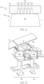
- FIG. 2 illustrates region 30 of compressor 10 in an embodiment wherein the SMEFs are realized as a number of circumferential channels or grooves 34 formed in the interior surface of engine casing 24.
- Grooves 34 surround or circumscribe rotor 18(a) and are located radially outboard of the tips of the rotor blades 36 (one of which is partially shown in FIG. 2 ).
- the illustrated rotor blade 36 includes a leading edge (abbreviated as "LE” in FIG. 2 ), a trailing edge (abbreviated as "TE” in FIG. 2 ), and an outer tip located radially adjacent treated region 30 of engine casing 24.
- Grooves 34 can be continuous or interrupted.
- a different groove configuration can be formed in region 30, such as axially-extending grooves or skewed grooves.
- a similar type of casing treatment can also be applied to region 32 shown in FIG. 1 and surrounding rotor 18(f).
- a different type of SMEFs can be applied to region 30 and/or region 32.
- FIG. 3 is an isometric cross-sectional view of a second, limited portion of multistage GTE compressor 10 to which SMEFs have further been applied.
- FIG. 3 illustrates region 31 of multistage axial compressor 10 in an implementation wherein the SMEFs are realized as upstream injection features 40 (one of which can be seen).
- upstream injections feature 40 include a stator core duct 42 and in-bleed conduit 44, which injects a small percentage of bleed flow into stator 20(d) upstream of stall limiting rotor 18(e) during operation of compressor 10.
- the bleed in-flow is deflected to the tips of rotor 18(e) for improved surge margin.
- the bleed flow can be passive or controlled by a secondary flow system (not shown), which controls the rate of stator hub injection.
- a different type of upstream injection may be integrated into region 31 of compressor 10.
- the pressure ratios sustainable by multistage GTE compressor 10 are advantageously increased due to the presence of SMEF-containing regions 30-32 integrated into compressor 10. Specifically, by applying SMEF to selected regions 30-32 corresponding to stall limiting rotors 18(a), 18(e), and 18(f), the pressure ratio capability of multistage GTE compressor 10 is improved. At the same time, the addition of SMEFs at locations corresponding to the rotors contained within intermediate compressor stages 16(b)-16(d) would be detrimental to compressor performance or would provide a limited performance benefit outweighed by added cost. In effect, the application of SMEFs has been optimized in the case of multistage GTE compressor 10 ( FIG. 1 ) such that performance gain is maximized, while production costs, the addition of weight, and other penalties are minimized. An exemplary process for optimizing compressor performance through the selective application of SMEFs to a multistage GTE compressor, such as compressor 10, will now be described in conjunction with FIG. 4 .
- FIG. 4 is a flowchart illustrating an exemplary method 50 for optimizing GTE compressor performance.
- Exemplary method 50 commences with the establishment of an optimized SMEF configuration for a multistage GTE compressor, such as compressor 10 shown in FIG. 1 (PROCESS BLOCK 52).
- the SMEFs configuration is "optimized" in the sense that SMEFs are applied to selected regions of the multistage GTE compressor targeted to boost the stall margin capability of a specific subset of rotors identified as "stall limiting rotors.”
- a plurality of engine speeds is first selected (STEP 54, FIG. 4 ). The selected engine speeds are distributed across an operational range of the gas turbine engine containing the compressor section.
- the selected engine speeds range from a minimum engine speed to a maximum engine speed and may include any number of intermediate speeds between the minimum and maximum engine speeds.
- the selected engine speeds may be separated by fixed intervals of 5% or 10% speed increments, wherein 100% is the engine speed at cruise. This example notwithstanding, the selected engine speeds need not occur at fixed internals in all embodiments.
- ground idle or start-up may be selected at the minimum engine speed, while the maximum selected engine speed may be equal to or greater than the maximum expected operational speed of the engine.
- At least one axial compressor rotor is identified as the "stall limiting rotor" for each selected engine speed.
- the "stall limiting rotors" are the axial compressor rotors that set compressor stall at the selected engine speeds.
- the stall limiting rotors can be identified by generating a compressor performance map utilizing a model of the multistage GTE compressor.
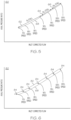
- the compressor performance map can be a graph of axial pressure ratio (vertical axis) versus inlet corrected flow (horizontal axis) plotting the speed lines for the multistage GTE compressor at each of the selected engine speeds.
- compressor performance map 60 refers to the ratio of outlet pressure over inlet pressure at each axial compressor stage, while the term “corrected flow” refers to the mass flow rate through the compressor stage corrected to standard day conditions.
- FIG. 5 An example of such a compressor performance map 60 is illustrated in FIG. 5 .
- compressor performance map 60 contains speed lines generated for the selected engine speeds of 70%, 80%, 85%, 90%, 95%, 100%, and 105% (wherein 100% is the engine speed at cruise). While these speed lines are shown on a single map for purposes of comparison, it will be appreciated that a different map may be generated for each speed line in actual implementations of method 50.
- Compressor performance map 60 shown in FIG. 5 can be generated utilizing either a physical model or a virtual model of the multistage GTE compressor.
- the model can be operated at each selected engine speed, while the axial pressure ratio is gradually increased by, for example, modulating an exhaust valve supplying airflow to the model.
- the axial pressure ratio can be gradually increased at a given engine speed until compressor stall is reached, at which point the speed line corresponding to the tested engine speed terminates.
- Pressure measurements are taken during this process at each of the axial compressor rotors and possibly at other locations along the compressor. Any suitable measurement equipment can be utilized for this purpose including, but not limited to, high response equipment.
- the pressure measurements are then analyzed to determine which rotor or rotors set stall at the tested engine speed. This process is repeated at the other selected engine speeds to identify the stall limiting rotor for each of the selected engine speeds.
- a similar process is performed when a virtual model is utilized to generate compressor performance map 60.
- a specialized computer program can be utilized to analyze the virtual model of the multistage GTE compressor. The computer program is utilized to generate a speed line for each of the selected engine speeds as previously described. When stall is reached at a given one of the selected engine speeds, the data is analyzed to identify which rotor or rotors sets stall at the selected engine speed.
- computation fluid dynamic analysis is utilized to identify the stall limiting stages by numerical instabilities; however, various other types of analysis can be utilized to identify the stall limiting stages in further embodiments.
- rotor R 1 (corresponding to rotor 18(a) in FIG. 1 ) may be identified as the stall limiting rotor for engine speeds 70%, 80%, 85%, and 90% (indicated by double-headed arrow 62 in FIG. 5 ).
- Rotor R 5 (corresponding to rotor 18(e) in FIG. 1 ) may be identified as the stall limiting rotor for engine speed 95% (indicated by double-headed arrow 64 in FIG. 5 ).
- rotor R 6 (corresponding to rotor 18(f) in FIG.
- SMEFs may consequently be applied to a model of compressor 10 at locations corresponding to rotors 18(a), 18(e), and 18(f), such as the locations identified in FIG. 1 by cross-hatched regions 30-32.
- a stall line 68 can be extrapolated for the compressor model by connecting and extending the upper terminal ends of the speed lines includes in compressor performance map 60.
- SMEFs are next applied to the compressor model at locations corresponding to stall limiting rotors identified during STEP 56.
- the SMEFs can be applied analytically by utilizing the computer program to adjust the virtual model of the compressor.
- the SMEFs can be physically added to or implemented into the compressor model.
- the casing sections surrounding the rotors of the stall limiting stages can be removed and replaced by treated casing sections; that is, casing sections having grooves or other casing treatment features formed therein.
- Additional computer analysis and/or additional flow testing can then be carried-out to answer the following query, which is presented at STEP 72 of exemplary method 50 ( FIG. 4 ): "Is a predetermined stall threshold surpassed at each of the multiple engine speeds?"
- a second or revised compressor performance map can be generated based upon the virtual or physical model after the SMEFs have been applied to selected regions thereof.
- An example of such a revised compressor performance map that can be generated during STEP 72 ( FIG. 4 ) is described below in conjunction with FIG. 6 .
- the method may proceed to STEP 86 (production of a multistage GTE compressor including the optimized SMEF configuration) when a minimal, acceptable level of stall margin is achieved at each of the multiple engine speeds.
- FIG. 6 illustrates a revised compressor performance map 80 generated during STEP 72 of exemplary method 50 ( FIG. 4 ).
- the improved stall line of the compressor model is represented by dashed line 82 connecting the upper terminal ends of stall lines, which have been extended by virtue of the selective addition of SMEFs during STEP 70 ( FIG. 4 ).
- the stall capability of the compressor model has improved across the entirety of the engine's operational speed range. Specifically, the speed line at each of the selected engine speeds now extends to a higher axial pressure ratio before stall is reached, as generally represented by the upper segments of the speed lines located between original stall line 68 and improved stall line 82.
- a predetermined stall threshold (represented in FIG. 6 by markers 84) has now been surpassed.
- the inquiry posed at STEP 72 is answered in the affirmative, and PROCESS BLOCK 52 is completed with the establishment of an optimized SMEF configuration.
- One or more multistage GTE compressor can now be produced to include the optimized SMEF configuration (STEP 86), and method 50 concludes.
- method 50 returns to STEP 56 and the above-described steps of identifying the stall limiting rotors, applying SMEFs to selected locations corresponding to the stall limiting rotors, and then retesting the compressor module are repeated.
- the threshold for determining whether to advance to STEP 86 from decision STEP 72 can be based upon whether a minimal acceptable stall margin is achieved at each selected engine speed in alternative implementations of method 50.
- the foregoing has thus provided methods for producing a multistage GTE compressor wherein compressor performance is optimized through the selective application of SMEFs to a locations corresponding to a number of stall limiting rotors.
- the stall margin of the compressor can generally be maintained, while aerodynamic loading is favorably increased.
- the pressure ratios sustained during operation of the compressor can be increased to enhance overall GTE performance.
- the foregoing SMEF optimization process avoids adding further stages to the compressor or increasing in the rotational speed over which the multistage GTE compressor operates.
- SMEFs can be integrated into a minimum number of compressor stages, while maintaining the desired stall margin of the compressor across the entire operating range of the GTE.
Landscapes
- Engineering & Computer Science (AREA)
- Mechanical Engineering (AREA)
- General Engineering & Computer Science (AREA)
- Structures Of Non-Positive Displacement Pumps (AREA)
Claims (3)
- Verfahren (50) zum Herstellen eines mehrstufigen Gasturbinenmaschinen-(GTE)-Kompressors (10), der eine Reihe von axialen Kompressorstufen (16) umfasst, die jeweils einen Rotor (18) enthalten, der an einer Welle (26) einer Gasturbinenmaschine montiert ist, wobei das Verfahren umfasst:Auswählen (54) einer Vielzahl von Maschinendrehzahlen, die über einen Betriebs-Drehzahlbereich der Gasturbinenmaschine verteilt sind;Identifizieren (56) eines oder mehrerer den Strömungsabriss begrenzender Rotoren bei jeder der ausgewählten Maschinendrehzahlen;Einrichten (52) einer optimierten Konfiguration eines Strömungsabrissgrenzen-Erweiterungsmerkmals (SMEF), in der SMEFs an ausgewählten Stellen (30, 31, 32), die den Strömungsabriss begrenzenden Rotoren entsprechen, in den mehrstufigen GTE-Kompressor integriert sind; undProduzieren (86) des mehrstufigen GTE-Kompressors gemäß der optimierten SMEF-Konfiguration;
wobei das Einrichten umfasst:Einrichten der optimierten SMEF-Konfiguration, so dass sie eine erste Art von Strömungsabriss-Verbesserungsmerkmal einschließt, das an einer Stelle angeordnet ist, die einem ersten den Strömungsabriss begrenzenden Rotor entspricht, und so dass sie eine zweite, unterschiedliche Art von Strömungsabriss-Verbesserungsmerkmal einschließt, das an einer Stelle angeordnet ist, die einem zweiten den Strömungsabriss begrenzenden Rotor entspricht;Anwenden (70) von SMEFs, nach dem Identifizieren eines oder mehrerer den Strömungsabriss begrenzender Rotoren bei jeder der ausgewählten Maschinendrehzahlen, auf ein Modell des mehrstufigen GTE-Kompressors an den ausgewählten Stellen, die den Strömungsabriss begrenzenden Rotoren entsprechen, wobei die erste Art von Strömungsabriss-Verbesserungsmerkmal Rillen (34) einschließt, die in einem Maschinengehäuse (24) gebildet sind, das den ersten den Strömungsabriss begrenzenden Rotor umgibt, und die zweite Art von Strömungsabriss-Verbesserungsmerkmal stromaufwärtige Einspritz-Merkmale (40) einschließt, die stromaufwärts vom zweiten den Strömungsabriss begrenzenden Rotor (18) in dessen Strömungsfeld positioniert sind, um einen Druckluftstrom an einer Stelle nah an einer Nabe eines Stators unmittelbar stromaufwärts vom zweiten den Strömungsabriss begrenzenden Rotor in den Hauptströmungsweg zu leiten;erneutes Testen des Modells nach dem Anwenden der SMEFs auf das Modell, um zu ermitteln, ob ein vorbestimmter Strömungsabriss-Schwellenwert bei jeder der ausgewählten Maschinendrehzahlen überschritten wird;Verwenden der Stellen, an denen die SMEFs auf das Modell angewendet wurden, wenn der vorbestimmte Strömungsabriss-Schwellenwert bei jeder der ausgewählten Maschinendrehzahlen überschritten wird, um die optimierte SMEF-Konfiguration einzurichten; undWiederholen (72) der Schritte des Anwendens und erneuten Testens, wenn der vorbestimmte Strömungsabriss-Schwellenwert nicht bei jeder der ausgewählten Maschinendrehzahlen überschritten wird. - Verfahren (50) nach Anspruch 1, wobei das Identifizieren umfasst:Auftragen einer Drehzahllinie für jede der ausgewählten Maschinendrehzahlen auf einer Kompressorleistungs-Abbildung (60, 80), während das im Modell des mehrstufigen GTE-Kompressors (10) angelegte axiale Druckverhältnis erhöht wird, bis der Strömungsabriss erreicht ist; undVerwenden von im Modell gesammelten Daten nach Erreichen des Strömungsabrisses bei jeder der ausgewählten Maschinendrehzahlen, um zu ermitteln, welcher der in der Reihe axialer Kompressorstufen (16) enthaltenen Rotoren (18) der den Strömungsabriss begrenzende Rotor bei jeder der ausgewählten Maschinendrehzahlen ist.
- Verfahren nach Anspruch 1, wobei der erste den Strömungsabriss begrenzende Rotor den führenden Rotor im mehrstufigen GTE-Kompressor umfasst.
Applications Claiming Priority (1)
| Application Number | Priority Date | Filing Date | Title |
|---|---|---|---|
| US14/612,404 US9932985B2 (en) | 2015-02-03 | 2015-02-03 | Gas turbine engine compressors having optimized stall enhancement feature configurations and methods for the production thereof |
Publications (2)
| Publication Number | Publication Date |
|---|---|
| EP3054166A1 EP3054166A1 (de) | 2016-08-10 |
| EP3054166B1 true EP3054166B1 (de) | 2023-07-12 |
Family
ID=55299283
Family Applications (1)
| Application Number | Title | Priority Date | Filing Date |
|---|---|---|---|
| EP16153522.4A Active EP3054166B1 (de) | 2015-02-03 | 2016-01-29 | Strömungsabriss-verminderung in einem mehrstufigen verdichter |
Country Status (2)
| Country | Link |
|---|---|
| US (3) | US9932985B2 (de) |
| EP (1) | EP3054166B1 (de) |
Families Citing this family (9)
| Publication number | Priority date | Publication date | Assignee | Title |
|---|---|---|---|---|
| EP2971547B1 (de) * | 2013-03-12 | 2020-01-01 | United Technologies Corporation | Freitragender stator mit wirbelerzeugungsfunktion |
| US10066640B2 (en) * | 2015-02-10 | 2018-09-04 | United Technologies Corporation | Optimized circumferential groove casing treatment for axial compressors |
| EP3131025A1 (de) * | 2015-08-14 | 2017-02-15 | Siemens Aktiengesellschaft | Verfahren zur vorhersage von pumpen in einem gasverdichter |
| US10132323B2 (en) * | 2015-09-30 | 2018-11-20 | General Electric Company | Compressor endwall treatment to delay compressor stall |
| US11156092B2 (en) * | 2019-02-07 | 2021-10-26 | Honeywell International Inc. | Multistage axial-centrifugal compressor systems and methods for manufacture |
| US11539316B2 (en) | 2019-07-30 | 2022-12-27 | General Electric Company | Active stability control of compression systems utilizing electric machines |
| US11967743B2 (en) | 2022-02-21 | 2024-04-23 | General Electric Company | Modular fuel cell assembly |
| US12170390B2 (en) | 2022-02-21 | 2024-12-17 | General Electric Company | Systems and method of operating a fuel cell assembly, a gas turbine engine, or both |
| US12221899B2 (en) | 2023-06-15 | 2025-02-11 | General Electric Company | Methods and apparatuses for blade locking |
Citations (1)
| Publication number | Priority date | Publication date | Assignee | Title |
|---|---|---|---|---|
| US20110299979A1 (en) * | 2010-06-08 | 2011-12-08 | Montgomery Matthew D | Method for Improving the Stall Margin of an Axial Flow Compressor Using a Casing Treatment |
Family Cites Families (7)
| Publication number | Priority date | Publication date | Assignee | Title |
|---|---|---|---|---|
| US4189939A (en) * | 1977-12-12 | 1980-02-26 | General Electric Company | Compact multimission aircraft propulsion simulator |
| GB2158879B (en) | 1984-05-19 | 1987-09-03 | Rolls Royce | Preventing surge in an axial flow compressor |
| DE69204861T2 (de) * | 1991-01-30 | 1996-05-23 | United Technologies Corp | Ventilatorgehäuse mit Rezirculationskanälen. |
| DE10218459B3 (de) | 2002-04-25 | 2004-01-15 | Mtu Aero Engines Gmbh | Verdichter in mehrstufiger Axialbauart |
| EP1862641A1 (de) | 2006-06-02 | 2007-12-05 | Siemens Aktiengesellschaft | Ringförmiger Strömungskanal für eine in Axialrichtung von einem Hauptstrom durchströmbare Strömungsmaschine |
| US8282336B2 (en) | 2007-12-28 | 2012-10-09 | General Electric Company | Instability mitigation system |
| GB201219617D0 (en) | 2012-11-01 | 2012-12-12 | Rolls Royce Deutschland & Co Kg | Bleed flow passage |
-
2015
- 2015-02-03 US US14/612,404 patent/US9932985B2/en active Active
-
2016
- 2016-01-29 EP EP16153522.4A patent/EP3054166B1/de active Active
-
2018
- 2018-02-26 US US15/904,890 patent/US10760580B2/en active Active
-
2020
- 2020-07-09 US US16/924,887 patent/US11466694B2/en active Active
Patent Citations (1)
| Publication number | Priority date | Publication date | Assignee | Title |
|---|---|---|---|---|
| US20110299979A1 (en) * | 2010-06-08 | 2011-12-08 | Montgomery Matthew D | Method for Improving the Stall Margin of an Axial Flow Compressor Using a Casing Treatment |
Non-Patent Citations (1)
| Title |
|---|
| KARL ENGEL ET AL: "CFD Simulations of the TP400 IPC With Enhanced Casing Treatment in Off-Design Operating Conditions", vol. GT2009-60324, 8 June 2009 (2009-06-08), pages 335 - 343, XP008180715, ISBN: 978-0-7918-4888-3, Retrieved from the Internet <URL:10.1115/GT2009-60324> * |
Also Published As
| Publication number | Publication date |
|---|---|
| US20160222973A1 (en) | 2016-08-04 |
| US11466694B2 (en) | 2022-10-11 |
| US10760580B2 (en) | 2020-09-01 |
| US9932985B2 (en) | 2018-04-03 |
| EP3054166A1 (de) | 2016-08-10 |
| US20180187690A1 (en) | 2018-07-05 |
| US20200340486A1 (en) | 2020-10-29 |
Similar Documents
| Publication | Publication Date | Title |
|---|---|---|
| US11466694B2 (en) | Gas turbine engine compressors having optimized stall enhancement feature configurations and methods for the production thereof | |
| US9726084B2 (en) | Compressor bleed self-recirculating system | |
| US10046424B2 (en) | Rotors with stall margin and efficiency optimization and methods for improving gas turbine engine performance therewith | |
| US10047620B2 (en) | Circumferentially varying axial compressor endwall treatment for controlling leakage flow therein | |
| JP6468414B2 (ja) | 圧縮機静翼、軸流圧縮機、及びガスタービン | |
| US9810157B2 (en) | Compressor shroud reverse bleed holes | |
| US10385871B2 (en) | Method and system for compressor vane leading edge auxiliary vanes | |
| EP3361053A1 (de) | Behandlung eines gerillten mantelgehäuses für einen hochdruckverdichter in einem turbinentriebwerk | |
| US20160153465A1 (en) | Axial compressor endwall treatment for controlling leakage flow therein | |
| US9650916B2 (en) | Turbomachine cooling systems | |
| EP3061975B1 (de) | Axialverdichter mit fluidrückführung | |
| EP3208467A1 (de) | Verdichterrotor zur abschwächung von überschall- und/oder resonantem stress | |
| US20170314509A1 (en) | Turbofan assembly and method of assembling | |
| EP2725233A1 (de) | Laufschaufel für einen Verdichter | |
| RU2525365C2 (ru) | Центробежная крыльчатка компрессора | |
| US11608744B2 (en) | System and method for air injection passageway integration and optimization in turbomachinery | |
| EP2644830B1 (de) | Geräuschverminderung in einer Turbomaschine und zugehörige Verfahren dafür | |
| US20180156236A1 (en) | Gas turbine engine bleed configuration | |
| US10495111B2 (en) | Compressor stage | |
| US20180112674A1 (en) | Compressor rotor of a fluid flow machine | |
| US20180073381A1 (en) | Method for designing a fluid flow engine and fluid flow engine |
Legal Events
| Date | Code | Title | Description |
|---|---|---|---|
| PUAI | Public reference made under article 153(3) epc to a published international application that has entered the european phase |
Free format text: ORIGINAL CODE: 0009012 |
|
| 17P | Request for examination filed |
Effective date: 20160129 |
|
| AK | Designated contracting states |
Kind code of ref document: A1 Designated state(s): AL AT BE BG CH CY CZ DE DK EE ES FI FR GB GR HR HU IE IS IT LI LT LU LV MC MK MT NL NO PL PT RO RS SE SI SK SM TR |
|
| AX | Request for extension of the european patent |
Extension state: BA ME |
|
| STAA | Information on the status of an ep patent application or granted ep patent |
Free format text: STATUS: EXAMINATION IS IN PROGRESS |
|
| 17Q | First examination report despatched |
Effective date: 20190513 |
|
| RAP3 | Party data changed (applicant data changed or rights of an application transferred) |
Owner name: HONEYWELL INTERNATIONAL INC. |
|
| GRAP | Despatch of communication of intention to grant a patent |
Free format text: ORIGINAL CODE: EPIDOSNIGR1 |
|
| STAA | Information on the status of an ep patent application or granted ep patent |
Free format text: STATUS: GRANT OF PATENT IS INTENDED |
|
| INTG | Intention to grant announced |
Effective date: 20230217 |
|
| GRAS | Grant fee paid |
Free format text: ORIGINAL CODE: EPIDOSNIGR3 |
|
| GRAA | (expected) grant |
Free format text: ORIGINAL CODE: 0009210 |
|
| STAA | Information on the status of an ep patent application or granted ep patent |
Free format text: STATUS: THE PATENT HAS BEEN GRANTED |
|
| P01 | Opt-out of the competence of the unified patent court (upc) registered |
Effective date: 20230421 |
|
| AK | Designated contracting states |
Kind code of ref document: B1 Designated state(s): AL AT BE BG CH CY CZ DE DK EE ES FI FR GB GR HR HU IE IS IT LI LT LU LV MC MK MT NL NO PL PT RO RS SE SI SK SM TR |
|
| REG | Reference to a national code |
Ref country code: CH Ref legal event code: EP |
|
| REG | Reference to a national code |
Ref country code: DE Ref legal event code: R096 Ref document number: 602016080923 Country of ref document: DE |
|
| REG | Reference to a national code |
Ref country code: IE Ref legal event code: FG4D |
|
| REG | Reference to a national code |
Ref country code: LT Ref legal event code: MG9D |
|
| REG | Reference to a national code |
Ref country code: NL Ref legal event code: MP Effective date: 20230712 |
|
| REG | Reference to a national code |
Ref country code: AT Ref legal event code: MK05 Ref document number: 1587454 Country of ref document: AT Kind code of ref document: T Effective date: 20230712 |
|
| PG25 | Lapsed in a contracting state [announced via postgrant information from national office to epo] |
Ref country code: NL Free format text: LAPSE BECAUSE OF FAILURE TO SUBMIT A TRANSLATION OF THE DESCRIPTION OR TO PAY THE FEE WITHIN THE PRESCRIBED TIME-LIMIT Effective date: 20230712 |
|
| PG25 | Lapsed in a contracting state [announced via postgrant information from national office to epo] |
Ref country code: GR Free format text: LAPSE BECAUSE OF FAILURE TO SUBMIT A TRANSLATION OF THE DESCRIPTION OR TO PAY THE FEE WITHIN THE PRESCRIBED TIME-LIMIT Effective date: 20231013 |
|
| PG25 | Lapsed in a contracting state [announced via postgrant information from national office to epo] |
Ref country code: ES Free format text: LAPSE BECAUSE OF FAILURE TO SUBMIT A TRANSLATION OF THE DESCRIPTION OR TO PAY THE FEE WITHIN THE PRESCRIBED TIME-LIMIT Effective date: 20230712 |
|
| PG25 | Lapsed in a contracting state [announced via postgrant information from national office to epo] |
Ref country code: IS Free format text: LAPSE BECAUSE OF FAILURE TO SUBMIT A TRANSLATION OF THE DESCRIPTION OR TO PAY THE FEE WITHIN THE PRESCRIBED TIME-LIMIT Effective date: 20231112 |
|
| PG25 | Lapsed in a contracting state [announced via postgrant information from national office to epo] |
Ref country code: SE Free format text: LAPSE BECAUSE OF FAILURE TO SUBMIT A TRANSLATION OF THE DESCRIPTION OR TO PAY THE FEE WITHIN THE PRESCRIBED TIME-LIMIT Effective date: 20230712 Ref country code: RS Free format text: LAPSE BECAUSE OF FAILURE TO SUBMIT A TRANSLATION OF THE DESCRIPTION OR TO PAY THE FEE WITHIN THE PRESCRIBED TIME-LIMIT Effective date: 20230712 Ref country code: PT Free format text: LAPSE BECAUSE OF FAILURE TO SUBMIT A TRANSLATION OF THE DESCRIPTION OR TO PAY THE FEE WITHIN THE PRESCRIBED TIME-LIMIT Effective date: 20231113 Ref country code: NO Free format text: LAPSE BECAUSE OF FAILURE TO SUBMIT A TRANSLATION OF THE DESCRIPTION OR TO PAY THE FEE WITHIN THE PRESCRIBED TIME-LIMIT Effective date: 20231012 Ref country code: LV Free format text: LAPSE BECAUSE OF FAILURE TO SUBMIT A TRANSLATION OF THE DESCRIPTION OR TO PAY THE FEE WITHIN THE PRESCRIBED TIME-LIMIT Effective date: 20230712 Ref country code: LT Free format text: LAPSE BECAUSE OF FAILURE TO SUBMIT A TRANSLATION OF THE DESCRIPTION OR TO PAY THE FEE WITHIN THE PRESCRIBED TIME-LIMIT Effective date: 20230712 Ref country code: IS Free format text: LAPSE BECAUSE OF FAILURE TO SUBMIT A TRANSLATION OF THE DESCRIPTION OR TO PAY THE FEE WITHIN THE PRESCRIBED TIME-LIMIT Effective date: 20231112 Ref country code: HR Free format text: LAPSE BECAUSE OF FAILURE TO SUBMIT A TRANSLATION OF THE DESCRIPTION OR TO PAY THE FEE WITHIN THE PRESCRIBED TIME-LIMIT Effective date: 20230712 Ref country code: GR Free format text: LAPSE BECAUSE OF FAILURE TO SUBMIT A TRANSLATION OF THE DESCRIPTION OR TO PAY THE FEE WITHIN THE PRESCRIBED TIME-LIMIT Effective date: 20231013 Ref country code: FI Free format text: LAPSE BECAUSE OF FAILURE TO SUBMIT A TRANSLATION OF THE DESCRIPTION OR TO PAY THE FEE WITHIN THE PRESCRIBED TIME-LIMIT Effective date: 20230712 Ref country code: ES Free format text: LAPSE BECAUSE OF FAILURE TO SUBMIT A TRANSLATION OF THE DESCRIPTION OR TO PAY THE FEE WITHIN THE PRESCRIBED TIME-LIMIT Effective date: 20230712 Ref country code: AT Free format text: LAPSE BECAUSE OF FAILURE TO SUBMIT A TRANSLATION OF THE DESCRIPTION OR TO PAY THE FEE WITHIN THE PRESCRIBED TIME-LIMIT Effective date: 20230712 |
|
| PG25 | Lapsed in a contracting state [announced via postgrant information from national office to epo] |
Ref country code: PL Free format text: LAPSE BECAUSE OF FAILURE TO SUBMIT A TRANSLATION OF THE DESCRIPTION OR TO PAY THE FEE WITHIN THE PRESCRIBED TIME-LIMIT Effective date: 20230712 |
|
| REG | Reference to a national code |
Ref country code: DE Ref legal event code: R097 Ref document number: 602016080923 Country of ref document: DE |
|
| PG25 | Lapsed in a contracting state [announced via postgrant information from national office to epo] |
Ref country code: SM Free format text: LAPSE BECAUSE OF FAILURE TO SUBMIT A TRANSLATION OF THE DESCRIPTION OR TO PAY THE FEE WITHIN THE PRESCRIBED TIME-LIMIT Effective date: 20230712 Ref country code: RO Free format text: LAPSE BECAUSE OF FAILURE TO SUBMIT A TRANSLATION OF THE DESCRIPTION OR TO PAY THE FEE WITHIN THE PRESCRIBED TIME-LIMIT Effective date: 20230712 Ref country code: EE Free format text: LAPSE BECAUSE OF FAILURE TO SUBMIT A TRANSLATION OF THE DESCRIPTION OR TO PAY THE FEE WITHIN THE PRESCRIBED TIME-LIMIT Effective date: 20230712 Ref country code: DK Free format text: LAPSE BECAUSE OF FAILURE TO SUBMIT A TRANSLATION OF THE DESCRIPTION OR TO PAY THE FEE WITHIN THE PRESCRIBED TIME-LIMIT Effective date: 20230712 Ref country code: CZ Free format text: LAPSE BECAUSE OF FAILURE TO SUBMIT A TRANSLATION OF THE DESCRIPTION OR TO PAY THE FEE WITHIN THE PRESCRIBED TIME-LIMIT Effective date: 20230712 Ref country code: SK Free format text: LAPSE BECAUSE OF FAILURE TO SUBMIT A TRANSLATION OF THE DESCRIPTION OR TO PAY THE FEE WITHIN THE PRESCRIBED TIME-LIMIT Effective date: 20230712 |
|
| PLBE | No opposition filed within time limit |
Free format text: ORIGINAL CODE: 0009261 |
|
| STAA | Information on the status of an ep patent application or granted ep patent |
Free format text: STATUS: NO OPPOSITION FILED WITHIN TIME LIMIT |
|
| PG25 | Lapsed in a contracting state [announced via postgrant information from national office to epo] |
Ref country code: IT Free format text: LAPSE BECAUSE OF FAILURE TO SUBMIT A TRANSLATION OF THE DESCRIPTION OR TO PAY THE FEE WITHIN THE PRESCRIBED TIME-LIMIT Effective date: 20230712 |
|
| 26N | No opposition filed |
Effective date: 20240415 |
|
| PG25 | Lapsed in a contracting state [announced via postgrant information from national office to epo] |
Ref country code: SI Free format text: LAPSE BECAUSE OF FAILURE TO SUBMIT A TRANSLATION OF THE DESCRIPTION OR TO PAY THE FEE WITHIN THE PRESCRIBED TIME-LIMIT Effective date: 20230712 |
|
| PG25 | Lapsed in a contracting state [announced via postgrant information from national office to epo] |
Ref country code: MC Free format text: LAPSE BECAUSE OF FAILURE TO SUBMIT A TRANSLATION OF THE DESCRIPTION OR TO PAY THE FEE WITHIN THE PRESCRIBED TIME-LIMIT Effective date: 20230712 |
|
| PG25 | Lapsed in a contracting state [announced via postgrant information from national office to epo] |
Ref country code: MC Free format text: LAPSE BECAUSE OF FAILURE TO SUBMIT A TRANSLATION OF THE DESCRIPTION OR TO PAY THE FEE WITHIN THE PRESCRIBED TIME-LIMIT Effective date: 20230712 |
|
| REG | Reference to a national code |
Ref country code: CH Ref legal event code: PL |
|
| PG25 | Lapsed in a contracting state [announced via postgrant information from national office to epo] |
Ref country code: LU Free format text: LAPSE BECAUSE OF NON-PAYMENT OF DUE FEES Effective date: 20240129 |
|
| GBPC | Gb: european patent ceased through non-payment of renewal fee |
Effective date: 20240129 |
|
| PG25 | Lapsed in a contracting state [announced via postgrant information from national office to epo] |
Ref country code: LU Free format text: LAPSE BECAUSE OF NON-PAYMENT OF DUE FEES Effective date: 20240129 |
|
| PG25 | Lapsed in a contracting state [announced via postgrant information from national office to epo] |
Ref country code: GB Free format text: LAPSE BECAUSE OF NON-PAYMENT OF DUE FEES Effective date: 20240129 |
|
| PG25 | Lapsed in a contracting state [announced via postgrant information from national office to epo] |
Ref country code: BE Free format text: LAPSE BECAUSE OF NON-PAYMENT OF DUE FEES Effective date: 20240131 |
|
| PG25 | Lapsed in a contracting state [announced via postgrant information from national office to epo] |
Ref country code: FR Free format text: LAPSE BECAUSE OF NON-PAYMENT OF DUE FEES Effective date: 20240131 |
|
| PG25 | Lapsed in a contracting state [announced via postgrant information from national office to epo] |
Ref country code: CH Free format text: LAPSE BECAUSE OF NON-PAYMENT OF DUE FEES Effective date: 20240131 |
|
| PG25 | Lapsed in a contracting state [announced via postgrant information from national office to epo] |
Ref country code: GB Free format text: LAPSE BECAUSE OF NON-PAYMENT OF DUE FEES Effective date: 20240129 Ref country code: FR Free format text: LAPSE BECAUSE OF NON-PAYMENT OF DUE FEES Effective date: 20240131 Ref country code: CH Free format text: LAPSE BECAUSE OF NON-PAYMENT OF DUE FEES Effective date: 20240131 Ref country code: BE Free format text: LAPSE BECAUSE OF NON-PAYMENT OF DUE FEES Effective date: 20240131 |
|
| REG | Reference to a national code |
Ref country code: BE Ref legal event code: MM Effective date: 20240131 |
|
| PG25 | Lapsed in a contracting state [announced via postgrant information from national office to epo] |
Ref country code: BG Free format text: LAPSE BECAUSE OF FAILURE TO SUBMIT A TRANSLATION OF THE DESCRIPTION OR TO PAY THE FEE WITHIN THE PRESCRIBED TIME-LIMIT Effective date: 20230712 |
|
| PG25 | Lapsed in a contracting state [announced via postgrant information from national office to epo] |
Ref country code: BG Free format text: LAPSE BECAUSE OF FAILURE TO SUBMIT A TRANSLATION OF THE DESCRIPTION OR TO PAY THE FEE WITHIN THE PRESCRIBED TIME-LIMIT Effective date: 20230712 |
|
| PG25 | Lapsed in a contracting state [announced via postgrant information from national office to epo] |
Ref country code: IE Free format text: LAPSE BECAUSE OF NON-PAYMENT OF DUE FEES Effective date: 20240129 |
|
| PG25 | Lapsed in a contracting state [announced via postgrant information from national office to epo] |
Ref country code: IE Free format text: LAPSE BECAUSE OF NON-PAYMENT OF DUE FEES Effective date: 20240129 |
|
| PG25 | Lapsed in a contracting state [announced via postgrant information from national office to epo] |
Ref country code: CY Free format text: LAPSE BECAUSE OF FAILURE TO SUBMIT A TRANSLATION OF THE DESCRIPTION OR TO PAY THE FEE WITHIN THE PRESCRIBED TIME-LIMIT; INVALID AB INITIO Effective date: 20160129 |
|
| PG25 | Lapsed in a contracting state [announced via postgrant information from national office to epo] |
Ref country code: HU Free format text: LAPSE BECAUSE OF FAILURE TO SUBMIT A TRANSLATION OF THE DESCRIPTION OR TO PAY THE FEE WITHIN THE PRESCRIBED TIME-LIMIT; INVALID AB INITIO Effective date: 20160129 |
|
| PG25 | Lapsed in a contracting state [announced via postgrant information from national office to epo] |
Ref country code: TR Free format text: LAPSE BECAUSE OF FAILURE TO SUBMIT A TRANSLATION OF THE DESCRIPTION OR TO PAY THE FEE WITHIN THE PRESCRIBED TIME-LIMIT Effective date: 20230712 |
|
| PGFP | Annual fee paid to national office [announced via postgrant information from national office to epo] |
Ref country code: DE Payment date: 20260127 Year of fee payment: 11 |