EP3054148A1 - Fuel injection pump - Google Patents
Fuel injection pump Download PDFInfo
- Publication number
- EP3054148A1 EP3054148A1 EP14848563.4A EP14848563A EP3054148A1 EP 3054148 A1 EP3054148 A1 EP 3054148A1 EP 14848563 A EP14848563 A EP 14848563A EP 3054148 A1 EP3054148 A1 EP 3054148A1
- Authority
- EP
- European Patent Office
- Prior art keywords
- fuel injection
- valve
- fuel
- injection pump
- receiving element
- Prior art date
- Legal status (The legal status is an assumption and is not a legal conclusion. Google has not performed a legal analysis and makes no representation as to the accuracy of the status listed.)
- Withdrawn
Links
- 239000000446 fuel Substances 0.000 title claims abstract description 181
- 238000002347 injection Methods 0.000 title claims abstract description 152
- 239000007924 injection Substances 0.000 title claims abstract description 152
- 238000013016 damping Methods 0.000 claims abstract description 41
- 238000002485 combustion reaction Methods 0.000 claims abstract description 13
- 238000011144 upstream manufacturing Methods 0.000 claims abstract description 13
- 239000000779 smoke Substances 0.000 abstract description 18
- 230000007423 decrease Effects 0.000 description 10
- 230000008034 disappearance Effects 0.000 description 8
- 230000000694 effects Effects 0.000 description 7
- 230000003111 delayed effect Effects 0.000 description 6
- 230000006866 deterioration Effects 0.000 description 6
- 230000001360 synchronised effect Effects 0.000 description 4
- 230000001934 delay Effects 0.000 description 3
- 238000000034 method Methods 0.000 description 1
- 239000000243 solution Substances 0.000 description 1
- 239000004071 soot Substances 0.000 description 1
Images



Classifications
-
- F—MECHANICAL ENGINEERING; LIGHTING; HEATING; WEAPONS; BLASTING
- F02—COMBUSTION ENGINES; HOT-GAS OR COMBUSTION-PRODUCT ENGINE PLANTS
- F02M—SUPPLYING COMBUSTION ENGINES IN GENERAL WITH COMBUSTIBLE MIXTURES OR CONSTITUENTS THEREOF
- F02M59/00—Pumps specially adapted for fuel-injection and not provided for in groups F02M39/00 -F02M57/00, e.g. rotary cylinder-block type of pumps
- F02M59/20—Varying fuel delivery in quantity or timing
- F02M59/24—Varying fuel delivery in quantity or timing with constant-length-stroke pistons having variable effective portion of stroke
- F02M59/243—Varying fuel delivery in quantity or timing with constant-length-stroke pistons having variable effective portion of stroke caused by movement of cylinders relative to their pistons
-
- F—MECHANICAL ENGINEERING; LIGHTING; HEATING; WEAPONS; BLASTING
- F02—COMBUSTION ENGINES; HOT-GAS OR COMBUSTION-PRODUCT ENGINE PLANTS
- F02M—SUPPLYING COMBUSTION ENGINES IN GENERAL WITH COMBUSTIBLE MIXTURES OR CONSTITUENTS THEREOF
- F02M55/00—Fuel-injection apparatus characterised by their fuel conduits or their venting means; Arrangements of conduits between fuel tank and pump F02M37/00
- F02M55/04—Means for damping vibrations or pressure fluctuations in injection pump inlets or outlets
-
- F—MECHANICAL ENGINEERING; LIGHTING; HEATING; WEAPONS; BLASTING
- F02—COMBUSTION ENGINES; HOT-GAS OR COMBUSTION-PRODUCT ENGINE PLANTS
- F02M—SUPPLYING COMBUSTION ENGINES IN GENERAL WITH COMBUSTIBLE MIXTURES OR CONSTITUENTS THEREOF
- F02M59/00—Pumps specially adapted for fuel-injection and not provided for in groups F02M39/00 -F02M57/00, e.g. rotary cylinder-block type of pumps
- F02M59/02—Pumps specially adapted for fuel-injection and not provided for in groups F02M39/00 -F02M57/00, e.g. rotary cylinder-block type of pumps of reciprocating-piston or reciprocating-cylinder type
- F02M59/10—Pumps specially adapted for fuel-injection and not provided for in groups F02M39/00 -F02M57/00, e.g. rotary cylinder-block type of pumps of reciprocating-piston or reciprocating-cylinder type characterised by the piston-drive
-
- F—MECHANICAL ENGINEERING; LIGHTING; HEATING; WEAPONS; BLASTING
- F02—COMBUSTION ENGINES; HOT-GAS OR COMBUSTION-PRODUCT ENGINE PLANTS
- F02M—SUPPLYING COMBUSTION ENGINES IN GENERAL WITH COMBUSTIBLE MIXTURES OR CONSTITUENTS THEREOF
- F02M59/00—Pumps specially adapted for fuel-injection and not provided for in groups F02M39/00 -F02M57/00, e.g. rotary cylinder-block type of pumps
- F02M59/44—Details, components parts, or accessories not provided for in, or of interest apart from, the apparatus of groups F02M59/02 - F02M59/42; Pumps having transducers, e.g. to measure displacement of pump rack or piston
- F02M59/46—Valves
- F02M59/462—Delivery valves
-
- F—MECHANICAL ENGINEERING; LIGHTING; HEATING; WEAPONS; BLASTING
- F02—COMBUSTION ENGINES; HOT-GAS OR COMBUSTION-PRODUCT ENGINE PLANTS
- F02M—SUPPLYING COMBUSTION ENGINES IN GENERAL WITH COMBUSTIBLE MIXTURES OR CONSTITUENTS THEREOF
- F02M61/00—Fuel-injectors not provided for in groups F02M39/00 - F02M57/00 or F02M67/00
- F02M61/16—Details not provided for in, or of interest apart from, the apparatus of groups F02M61/02 - F02M61/14
- F02M61/18—Injection nozzles, e.g. having valve seats; Details of valve member seated ends, not otherwise provided for
-
- F—MECHANICAL ENGINEERING; LIGHTING; HEATING; WEAPONS; BLASTING
- F02—COMBUSTION ENGINES; HOT-GAS OR COMBUSTION-PRODUCT ENGINE PLANTS
- F02M—SUPPLYING COMBUSTION ENGINES IN GENERAL WITH COMBUSTIBLE MIXTURES OR CONSTITUENTS THEREOF
- F02M2200/00—Details of fuel-injection apparatus, not otherwise provided for
- F02M2200/28—Details of throttles in fuel-injection apparatus
-
- F—MECHANICAL ENGINEERING; LIGHTING; HEATING; WEAPONS; BLASTING
- F02—COMBUSTION ENGINES; HOT-GAS OR COMBUSTION-PRODUCT ENGINE PLANTS
- F02M—SUPPLYING COMBUSTION ENGINES IN GENERAL WITH COMBUSTIBLE MIXTURES OR CONSTITUENTS THEREOF
- F02M2200/00—Details of fuel-injection apparatus, not otherwise provided for
- F02M2200/30—Fuel-injection apparatus having mechanical parts, the movement of which is damped
- F02M2200/302—Fuel-injection apparatus having mechanical parts, the movement of which is damped using electrical means
-
- F—MECHANICAL ENGINEERING; LIGHTING; HEATING; WEAPONS; BLASTING
- F02—COMBUSTION ENGINES; HOT-GAS OR COMBUSTION-PRODUCT ENGINE PLANTS
- F02M—SUPPLYING COMBUSTION ENGINES IN GENERAL WITH COMBUSTIBLE MIXTURES OR CONSTITUENTS THEREOF
- F02M2200/00—Details of fuel-injection apparatus, not otherwise provided for
- F02M2200/30—Fuel-injection apparatus having mechanical parts, the movement of which is damped
- F02M2200/304—Fuel-injection apparatus having mechanical parts, the movement of which is damped using hydraulic means
-
- F—MECHANICAL ENGINEERING; LIGHTING; HEATING; WEAPONS; BLASTING
- F02—COMBUSTION ENGINES; HOT-GAS OR COMBUSTION-PRODUCT ENGINE PLANTS
- F02M—SUPPLYING COMBUSTION ENGINES IN GENERAL WITH COMBUSTIBLE MIXTURES OR CONSTITUENTS THEREOF
- F02M2200/00—Details of fuel-injection apparatus, not otherwise provided for
- F02M2200/31—Fuel-injection apparatus having hydraulic pressure fluctuations damping elements
- F02M2200/315—Fuel-injection apparatus having hydraulic pressure fluctuations damping elements for damping fuel pressure fluctuations
-
- F—MECHANICAL ENGINEERING; LIGHTING; HEATING; WEAPONS; BLASTING
- F02—COMBUSTION ENGINES; HOT-GAS OR COMBUSTION-PRODUCT ENGINE PLANTS
- F02M—SUPPLYING COMBUSTION ENGINES IN GENERAL WITH COMBUSTIBLE MIXTURES OR CONSTITUENTS THEREOF
- F02M59/00—Pumps specially adapted for fuel-injection and not provided for in groups F02M39/00 -F02M57/00, e.g. rotary cylinder-block type of pumps
- F02M59/02—Pumps specially adapted for fuel-injection and not provided for in groups F02M39/00 -F02M57/00, e.g. rotary cylinder-block type of pumps of reciprocating-piston or reciprocating-cylinder type
- F02M59/10—Pumps specially adapted for fuel-injection and not provided for in groups F02M39/00 -F02M57/00, e.g. rotary cylinder-block type of pumps of reciprocating-piston or reciprocating-cylinder type characterised by the piston-drive
- F02M59/102—Mechanical drive, e.g. tappets or cams
Definitions
- the present invention relates to techniques of a fuel injection pump.
- Fuel injection pumps are known as pumps that deliver, at high pressure, a fuel to be injected into a combustion chamber of a diesel engine.
- the fuel injection pump delivers a fuel that is pressure-fed by allowing a plunger to vertically slide inside a plunger barrel to a plurality of delivery valves and pressure-feeds the fuel to a fuel injection nozzle from each of the delivery valves (Patent Document 1, for example).
- the generation of white smoke also has a correlation with an initial injection rate.
- a combustion temperature is reduced.
- the reduction in the combustion temperature results in imperfect combustion.
- the imperfect combustion results in the generation of white smoke. That is, the generation of white smoke can be reduced by reducing the initial injection rate.
- Patent Document 1 JPH 11-44274 A
- a fuel injection pump is configured to deliver, at high pressure, a fuel to be injected into a combustion chamber of a diesel engine, and includes a delivery valve disposed in the middle of a path for pressure-feeding the fuel from a plunger to a fuel injection nozzle and a damping valve disposed on a downstream side of the delivery valve.
- the damping valve includes a valve element which has an orifice formed on an axial part of the valve element and is biased toward an upstream side by a damping valve spring and a receiving element which has a passage hole formed on an axial part of the receiving element and is configured to abut against the valve element.
- a recess communicating with the passage hole is formed on a face of the valve element, the face facing the receiving element.
- the recess is formed in a cylindrical shape.
- a fuel injection pump is configured to deliver, at high pressure, a fuel to be injected into a combustion chamber of a diesel engine, and includes a delivery valve disposed in the middle of a path for pressure-feeding the fuel from a plunger to a fuel injection nozzle and a damping valve disposed on a downstream side of the delivery valve.
- the damping valve includes a valve element which has an orifice formed on an axial part of the valve element and is biased toward an upstream side by a damping valve spring and a receiving element which has a passage hole formed on an axial part of the receiving element and is configured to abut against the valve element.
- a recess communicating with the passage hole is formed on a face of the receiving element, the face facing the valve element.
- the recess is formed in a cylindrical shape.
- the fuel injection pump of the present invention it is possible to reduce the resistance produced in the second half of fuel injection, reduce the initial injection rate, and thereby significantly reduce white smoke in exhaust gas.
- Fig. 1 illustrates the fuel injection pump 100 in partially sectional view and side view.
- the fuel injection pump 100 relates to Embodiment 1 of the fuel injection pump of the present invention.
- the fuel injection pump 100 is provided in a diesel engine.
- the fuel injection pump 100 delivers, at high pressure, a fuel to be injected into a combustion chamber of the diesel engine.
- the fuel injection pump 100 includes a pump housing 102 which has a hole formed from the upper face toward the lower side thereof and a tubular plunger barrel 103 which is inserted into the hole of the pump housing 102.
- a plunger 104 is vertically slidably inserted into the plunger barrel 103.
- a pressure chamber 107 is formed above the plunger 104.
- a tappet 108 is inserted under the plunger 104 in such a manner that the tappet 108 can vertically slide inside the pump housing 102 integrally with the plunger 104.
- a cam 109 abuts against the lower face of the tappet 108 through a roller 112.
- the plunger 104 and the tappet 108 are biased downward by a plunger spring 105.
- the cam 109 is disposed on a cam shaft 110.
- the cam shaft 110 is rotatably supported on the pump housing 102 of the fuel injection pump 100 through a cam bearing 111.
- a delivery valve 10 is disposed above the plunger 104. The delivery valve 10 will be described in detail below.
- the tappet 108 which is in sliding contact with the outer periphery of the cam 109 and the plunger 104 vertically slide in a reciprocating manner with the rotation of the cam shaft 110, so that a fuel is pressure-fed by a fuel feed pump (not illustrated).
- the plunger 104 sliding toward the upstream side (downward) opens a barrel port 106, and the pressure-fed fuel is thereby sucked into the pressure chamber 107.
- the fuel sucked into the pressure chamber 107 is pressurized when the plunger 104 slides toward the downstream side (upward).
- Fig. 2 illustrates the delivery valve 10 in partially sectional view and side view.
- the configuration of a conventional valve element and a conventional receiving element, and the configuration of a valve element 15 and a receiving element 16 of the present embodiment are enlarged and compared.
- the delivery valve 10 is provided with a tubular delivery valve case 11, a delivery valve body 13, and a delivery valve spring 14 which biases the delivery valve body 13 toward the delivery valve case 11.
- the delivery valve case 11 and the plunger barrel 103 are inserted into the hole which is formed on the pump housing 102 from the upper face toward the lower side thereof (refer to Fig. 1 ).
- the delivery valve body 13 is vertically slidably inserted into the lower part of a spring housing section 12d of a casing 12 and biased toward the delivery valve case 11 (downward) by the delivery valve spring 14.
- a space formed by the receiving element 16, the spring housing section 12d, and the delivery valve body 13 is referred to as a delivery chamber R.
- the casing 12 is a tubular member and inserted from the upper side of the fuel injection pump 100 into the hole which is formed on the pump housing 102 on the upper face thereof.
- a through hole is formed on an axial part of the casing 12.
- a fuel discharge port 12a, a small-diameter fuel passage 12b, a guide body housing section 12c, the spring housing section 12d, and a delivery valve case fitting section 12e are formed inside the through hole of the casing 12 in this order from the upper side.
- the fuel discharge port 12a is formed in a tapered shape expanding toward the downstream side on a downstream end of the through hole, and a high-pressure tube is connected to the fuel discharge port 12a.
- the small-diameter fuel passage 12b is formed under (on the upstream side of) the fuel discharge port 12a to receive one side of a damping valve spring 18.
- the guide body housing section 12c is formed on the upstream side of the small-diameter fuel passage 12b to house a guide body 19 and a damping valve 17.
- the damping valve 17 includes the valve element 15 and the receiving element 16.
- the damping valve 17 is configured in such a manner that the valve element 15 is biased downward (toward the upstream side) by the damping valve spring 18 so as to abut against the receiving element 16.
- the valve element 15 faces the receiving element 16.
- the valve element 15 is formed in a two-stage cylindrical shape and has an orifice 15a which vertically penetrates an axial part thereof.
- the valve element 15 has a cylindrical recess 15b which is recessed upward from the center of a face of the valve element 15, the face facing the receiving element 16.
- the recess 15b communicates with the orifice 15a.
- the recess 15b is formed in a cylindrical shape.
- the receiving element 16 is formed in a two-stage cylindrical shape and has a passage hole 16a which vertically penetrates an axial part thereof.
- the spring housing section 12d is formed on the upstream side of the guide body housing section 12c to house the delivery valve spring 14 and the upper part of the delivery valve body 13.
- the delivery valve case fitting section 12e which is fitted with the upper part of the delivery valve case 11 is formed under the spring housing section 12d.
- the delivery valve body 13 and the valve element 15 slide toward the downstream side (upward) to open the delivery valve 10 and the damping valve 17. Accordingly, the fuel is pressure-fed to a fuel injection nozzle (not illustrated) through the spring housing section 12d, the passage hole 16a, the small-diameter fuel passage 12b, and the fuel discharge port 12a.
- the resistance of the fuel flowing between the valve element 15 and the receiving element 16 immediately after the lift of the valve element 15 is similar to that in a conventional configuration due to a small gap between the valve element 15 and the receiving element 16 even when the recess 15b is formed.
- the recess 15b sufficiently reduces a distance having the minimum fuel passage width (the minimum gap between the valve element 15 and the receiving element 16) from a conventional distance L2 to a distance L1.
- the fuel injection amount is increased.
- the fuel injection rate decreases in the first half of the fuel injection and increases in the second half of the fuel injection. That is, an initial injection rate of the diesel engine is reduced.
- the delivery valve 10 makes it possible to reduce the initial injection rate of the fuel injection pump 100 and thereby significantly reduce white smoke in exhaust gas of the diesel engine.
- a delivery valve 20 The configuration of a delivery valve 20 will be described with reference to Fig. 3 .
- Fig. 3 illustrates the delivery valve 20 in partially sectional view and side view.
- the configuration of a conventional valve element and a conventional receiving element, and the configuration of a valve element 25 and a receiving element 26 of the present embodiment are enlarged and compared.
- the delivery valve 20 relates to Embodiment 2 of the fuel injection pump of the present invention.
- a delivery valve case 21, a casing 22, a delivery valve body 23, a delivery valve spring 24, a damping valve spring 28, and a guide body 29 of the delivery valve 20 respectively have configurations similar to the configurations of the delivery valve case 11, the casing 12, the delivery valve body 13, the delivery valve spring 14, the damping valve spring 18, and the guide body 19 of the delivery valve 10. Thus, description thereof will not be provided.
- a damping valve 27 includes the valve element 25 and the receiving element 26.
- the damping valve 27 is configured in such a manner that the valve element 25 is biased downward (toward the upstream side) by the damping valve spring 28 so as to abut against the receiving element 26.
- the valve element 25 is formed in a two-stage cylindrical shape and has an orifice 25a which vertically penetrates an axial part thereof.
- the receiving element 26 is formed in a two-stage cylindrical shape and has a passage hole 26a which vertically penetrates an axial part thereof.
- the receiving element 26 has a cylindrical recess 26b which is recessed downward from the center of a face of the receiving element 26, the face facing the valve element 25.
- the recess 26b communicates with the orifice 25a.
- the recess 26b is formed in a cylindrical shape.
- the delivery valve body 23 and the valve element 25 slide toward the downstream side (upward) to open the delivery valve 20 and the damping valve 27. Accordingly, the fuel is pressure-fed to a fuel injection nozzle (not illustrated) through a spring housing section 22d, the passage hole 26a, a small-diameter fuel passage 22b, and a fuel discharge port 22a.
- the resistance of the fuel flowing between the valve element 25 and the receiving element 26 immediately after the lift of the valve element 25 is similar to that in a conventional configuration due to a small gap between the valve element 25 and the receiving element 26 even when the recess 26b is formed.
- the recess 26b sufficiently reduces a distance having the minimum fuel passage width (the minimum gap between the valve element 25 and the receiving element 26) from a conventional distance L2 to a distance L1.
- the fuel injection amount is increased.
- the delivery valve 20 makes it possible to reduce the initial injection rate of the fuel injection pump 100 and thereby significantly reduce white smoke in exhaust gas of the diesel engine.
- a delivery valve 30 The configuration of a delivery valve 30 will be described with reference to Fig. 4 .
- Fig. 4 illustrates the delivery valve 30 in partially sectional view and side view.
- the delivery valve 30 relates to Embodiment 3 of the fuel injection pump of the present invention.
- a delivery valve case 31, a casing 32, a delivery valve body 33, and a delivery valve spring 34 of the delivery valve 30 respectively have configurations similar to the configurations of the delivery valve case 11, the casing 12, the delivery valve body 13, and the delivery valve spring 14 of the delivery valve 10. Thus, description thereof will not be provided.
- a damping valve 37 includes an inner valve element 35i, an outer valve element 35o, a receiving element 36, and a support 39.
- the inner valve element 35i is biased downward (toward the upstream side) from the support 39 by an inner damping valve spring 38i so as to abut against the receiving element 36.
- the outer valve element 35o is biased downward (toward the upstream side) from the casing 32 by an outer damping valve spring 38o so as to abut against the receiving element 36.
- the inner valve element 35i is formed in a two-stage cylindrical shape and has an orifice 35a which vertically penetrates an axial part thereof.
- the outer valve element 35o is formed in an annular shape.
- the receiving element 36 is formed in a two-stage cylindrical shape and has a passage hole 36a which vertically penetrates an axial part thereof.
- the support 39 is formed in a two-stage cylindrical shape and has a passage hole 39a which vertically penetrates an axial part thereof.
- the outer valve element 35o is engaged with a stepped part of the inner valve element 35i. That is, a biasing force of the outer damping valve spring 38o and a biasing force of the inner damping valve spring 38i are applied to the inner valve element 35i.
- Figs. 5(A) to 5(C) illustrate the delivery valve 30 in partially sectional view and side view.
- the delivery valve 30 makes it possible to reduce the initial injection rate of the fuel injection pump 100 and thereby significantly reduce white smoke in exhaust gas of the diesel engine.
- Fig. 6 schematically illustrates the fuel injection pump 400.
- the fuel injection pump 400 relates to Embodiment 4 of the fuel injection pump of the present invention.
- the fuel injection pump 400 is similar to the fuel injection pump 100 according to Embodiment 1 except for a part particularly described below.
- a recess 408a is formed on the lower face of a tappet 408. There is not a roller between the recess 408a and the lower face of a tappet 408.
- the recess 408a is formed in a circular arc shape when viewed from a direction perpendicular to a cam shaft 410.
- the recess 408a varies a contact position between a cam 409 and the recess 408a depending on the shape of the cam 409.
- the timing and amount of vertical reciprocating slide of a plunger 404 caused by the cam 409 are varied. That is, the fuel injection amount can be varied without changing the profile of the cam 409.
- the recess 408a is formed so that the fuel injection amount increases in the second half of fuel injection.
- Such a configuration enables an initial injection rate of the diesel engine to be reduced. That is, it is possible to reduce the initial injection rate of the fuel injection pump 400 and thereby significantly reduce white smoke in exhaust gas of the diesel engine.
- Fig. 7 illustrates the fuel injection pump 500 in partially sectional view and side view.
- the fuel injection pump 500 relates to Embodiment 5 of the fuel injection pump of the present invention.
- the fuel injection pump 500 is similar to the fuel injection pump 100 according to Embodiment 1 except for a part particularly described below.
- a capacity addition mechanism 510 communicates with a delivery chamber R.
- the capacity of the capacity addition mechanism 510 decreases as the engine speed increases and increases as the engine speed decreases.
- the capacity addition mechanism 510 is provided with a passage 511, a cylinder chamber 512, a fuel chamber 512a, a piston 513, a solenoid 514, and a controller 550.
- the cylinder chamber 512 forms the fuel chamber 512a by the piston 513.
- the passage 511 allows the delivery chamber R formed on a casing and the fuel chamber 512a to communicate with each other.
- the piston 513 slides inside the cylinder chamber 512 to increase or reduce the capacity of the fuel chamber 512a.
- the solenoid 514 is connected to the controller 550 to drive the piston 513 to reciprocate.
- the controller 550 is connected to the solenoid 514 and an engine speed senor 551 which detects the engine speed of an engine (not illustrated) provided with the fuel injection pump 500.
- the controller 550 has a function of controlling the solenoid 514 to drive the piston 513 so as to reduce the capacity of the cylinder chamber 512 as the engine speed increases and controlling the solenoid 514 to drive the piston 513 so as to increase the capacity of the cylinder chamber 512 as the engine speed decreases.
- the capacity of the cylinder chamber 512 of the capacity addition mechanism 510 is added to the capacity of the conventional delivery chamber R.
- a time lag occurs when the injection pressure is transmitted to a fuel injection nozzle (not illustrated) to delay a fuel injection timing. That is, providing the capacity addition mechanism 510 delays the fuel injection timing over the entire engine speed (first control).
- the capacity addition mechanism 510 the capacity of the cylinder chamber 512 is reduced as the engine speed increases.
- the time lag is eliminated before the injection pressure is transmitted to the fuel injection nozzle (not illustrated) to advance the fuel injection timing. That is, the fuel injection timing is advanced compared to that during the first control only when the engine speed is high (second control).
- the capacity addition mechanism 510 enables the generation of Sd and deterioration in a white smoke disappearance time to be improved. That is, since the fuel injection timing is delayed over the entire engine speed by the first control and advanced by the second control only when the engine speed is high, the generation of Sd and the deterioration in the white smoke disappearance time can be improved.
- Fig. 8 illustrates the fuel injection pump 600 in partially sectional view and side view.
- the fuel injection pump 600 relates to Embodiment 6 of the fuel injection pump of the present invention.
- the fuel injection pump 600 is similar to the fuel injection pump 100 according to Embodiment 1 except for a part particularly described below.
- a capacity addition mechanism 620 communicates with a delivery chamber R.
- the capacity of the capacity addition mechanism 620 decreases as the engine speed increases and increases as the engine speed decreases.
- the capacity addition mechanism 620 is provided with a passage 621, a cylinder chamber 622, a piston 623, a switching valve 624, and a hydraulic pump 625.
- the passage 621, the cylinder chamber 622, a fuel chamber 622a, and the piston 623 respectively have configurations similar to the configurations of the passage 511, the cylinder chamber 512, and the piston 513 of Embodiment 5. Thus, description thereof will not be provided.
- the cylinder chamber 622 is divided into the fuel chamber 622a and an operating oil chamber 622b by the piston 623.
- the switching valve 624 is disposed between the hydraulic pump 625 and the cylinder chamber 622.
- the switching valve 624 has a function of supplying an operating oil to the operating oil chamber 622b of the cylinder chamber 622 when the pressure of the operating oil fed from the hydraulic pump 625 becomes a predetermined pressure or more.
- the hydraulic pump 625 is driven by an engine provided with the fuel injection pump 600.
- the capacity of the cylinder chamber 622 of the capacity addition mechanism 620 is added to the capacity of the conventional delivery chamber R.
- a time lag occurs when the injection pressure is transmitted to a fuel injection nozzle (not illustrated) to delay a fuel injection timing. That is, providing the capacity addition mechanism 620 delays the fuel injection timing over the entire engine speed (first control).
- the switching valve 624 when the operating pressure by the hydraulic pump 625 increases to a predetermined pressure or more as the engine speed increases, the switching valve 624 is switched to supply the operating oil to the operating oil chamber 62b. Accordingly, the piston 623 inside the cylinder chamber 622 moves toward the fuel chamber 622a to reduce the capacity of the fuel chamber 622a.
- the fuel injection timing is delayed over the entire engine speed by the first control, the time lag is eliminated before the injection pressure is transmitted to the fuel injection nozzle (not illustrated) to advance the fuel injection timing. That is, the fuel injection timing is advanced compared to that during the first control only when the engine speed is high (second control).
- the capacity addition mechanism 620 enables the generation of Sd and deterioration in a white smoke disappearance time to be improved. That is, since the fuel injection timing is delayed over the entire engine speed by the first control and advanced by the second control only when the engine speed is high, the generation of Sd and the deterioration in the white smoke disappearance time can be improved.
- Fig. 9 illustrates the fuel injection pump 700 in partially sectional view and side view.
- the fuel injection pump 700 relates to Embodiment 7 of the fuel injection pump of the present invention.
- the fuel injection pump 700 is similar to the fuel injection pump 100 according to Embodiment 1 except for a part particularly described below.
- a capacity addition mechanism 730 communicates with a delivery chamber R.
- the capacity of the capacity addition mechanism 730 decreases as the engine speed increases and increases as the engine speed decreases.
- the capacity addition mechanism 730 is provided with a passage 731, a cylinder chamber 732, a piston 733, and a synchronous link 734.
- the passage 731, the cylinder chamber 732, a combustion chamber 732a, and the piston 733 respectively have configurations similar to the configurations of the passage 511, the cylinder chamber 512, the combustion chamber 512a, and the piston 513 of Embodiment 5. Thus, description thereof will not be provided.
- a regulator lever 752 is disposed on an engine provided with the fuel injection pump 700.
- the regulator lever 752 is operated to turn to adjust the fuel injection amount of the fuel injection pump 100 to control the engine speed.
- the synchronous link 734 supports the piston 733 and the regulator valve 752 so as to reduce the capacity of the cylinder chamber 732 when the regulator lever 752 is turned to control the engine speed at a high speed and increase the capacity of the cylinder chamber 732 when the regulator lever 752 is turned to control the engine speed at a low speed.
- the capacity of the cylinder chamber 732 of the capacity addition mechanism 730 is added to the capacity of the conventional delivery chamber R.
- a time lag occurs when the injection pressure is transmitted to a fuel injection nozzle (not illustrated) to delay a fuel injection timing. That is, providing the capacity addition mechanism 720 delays the fuel injection timing over the entire engine speed (first control).
- the capacity of the cylinder chamber 732 is reduced by turning the regulator lever 752 so as to increase the engine speed.
- the time lag is eliminated before the injection pressure is transmitted to the fuel injection nozzle (not illustrated) to advance the fuel injection timing. That is, the fuel injection timing is advanced compared to that during the first control only when the engine speed is high (second control).
- the capacity addition mechanism 730 enables the generation of Sd and deterioration in a white smoke disappearance time to be improved. That is, since the fuel injection timing is delayed over the entire engine speed by the first control and advanced by the second control only when the engine speed is high, the generation of Sd and the deterioration in the white smoke disappearance time can be improved.
- the present invention is applicable to a fuel injection pump.
Landscapes
- Engineering & Computer Science (AREA)
- Chemical & Material Sciences (AREA)
- Combustion & Propulsion (AREA)
- Mechanical Engineering (AREA)
- General Engineering & Computer Science (AREA)
- Fuel-Injection Apparatus (AREA)
Abstract
Description
- The present invention relates to techniques of a fuel injection pump.
- Fuel injection pumps are known as pumps that deliver, at high pressure, a fuel to be injected into a combustion chamber of a diesel engine. The fuel injection pump delivers a fuel that is pressure-fed by allowing a plunger to vertically slide inside a plunger barrel to a plurality of delivery valves and pressure-feeds the fuel to a fuel injection nozzle from each of the delivery valves (
Patent Document 1, for example). - In a diesel engine, it is necessary to significantly reduce "soot (hereinbelow, referred to as Sd)" due to restriction. In a diesel engine, it is effective to delay a fuel injection timing to significantly reduce Sd. On the other hand, in a diesel engine, the delay in the fuel injection timing significantly deteriorates a white smoke disappearance time (a time from engine start to the disappearance of white smoke).
- On the other hand, the generation of white smoke also has a correlation with an initial injection rate. In a diesel engine, when the initial injection rate is high, a combustion temperature is reduced. The reduction in the combustion temperature results in imperfect combustion. The imperfect combustion results in the generation of white smoke. That is, the generation of white smoke can be reduced by reducing the initial injection rate.
- Patent Document 1: JPH 11-44274 A
- It is an object of the present invention to provide a fuel injection pump that enables white smoke in exhaust gas to be significantly reduced.
- A fuel injection pump according to a first aspect of the present invention is configured to deliver, at high pressure, a fuel to be injected into a combustion chamber of a diesel engine, and includes a delivery valve disposed in the middle of a path for pressure-feeding the fuel from a plunger to a fuel injection nozzle and a damping valve disposed on a downstream side of the delivery valve. The damping valve includes a valve element which has an orifice formed on an axial part of the valve element and is biased toward an upstream side by a damping valve spring and a receiving element which has a passage hole formed on an axial part of the receiving element and is configured to abut against the valve element. A recess communicating with the passage hole is formed on a face of the valve element, the face facing the receiving element.
- Preferably, in the fuel injection pump according to the first aspect of the present invention, the recess is formed in a cylindrical shape.
- A fuel injection pump according to a second aspect of the present invention is configured to deliver, at high pressure, a fuel to be injected into a combustion chamber of a diesel engine, and includes a delivery valve disposed in the middle of a path for pressure-feeding the fuel from a plunger to a fuel injection nozzle and a damping valve disposed on a downstream side of the delivery valve. The damping valve includes a valve element which has an orifice formed on an axial part of the valve element and is biased toward an upstream side by a damping valve spring and a receiving element which has a passage hole formed on an axial part of the receiving element and is configured to abut against the valve element. A recess communicating with the passage hole is formed on a face of the receiving element, the face facing the valve element.
- Preferably, in the fuel injection pump according to the second aspect of the present invention, the recess is formed in a cylindrical shape.
- According to the fuel injection pump of the present invention, it is possible to reduce the resistance produced in the second half of fuel injection, reduce the initial injection rate, and thereby significantly reduce white smoke in exhaust gas.
-
-
Fig. 1 is a side view showing the configuration of a fuel injection pump. -
Fig. 2 is a schematic view showing the configuration of a delivery valve according toEmbodiment 1. -
Fig. 3 is a schematic view showing the configuration of a delivery valve according to Embodiment 2. -
Fig. 4 is a schematic view showing the configuration of a delivery valve according to Embodiment 3. -
Figs. 5(A) to 5(C) are schematic views showing the action of the delivery valve according to Embodiment 3. -
Fig. 6 is a side view showing the configuration of a fuel injection pump according to Embodiment 4. -
Fig. 7 is a side view showing the configuration of a fuel injection pump according to Embodiment 5. -
Fig. 8 is a side view showing the configuration of a fuel injection pump according to Embodiment 6. -
Fig. 9 is a side view showing the configuration of a fuel injection pump according to Embodiment 7. -
EMBODIMENT 1 - The configuration of a
fuel injection pump 100 will be described with reference toFig. 1 . -
Fig. 1 illustrates thefuel injection pump 100 in partially sectional view and side view. - The
fuel injection pump 100 relates toEmbodiment 1 of the fuel injection pump of the present invention. Thefuel injection pump 100 is provided in a diesel engine. Thefuel injection pump 100 delivers, at high pressure, a fuel to be injected into a combustion chamber of the diesel engine. - The
fuel injection pump 100 includes apump housing 102 which has a hole formed from the upper face toward the lower side thereof and atubular plunger barrel 103 which is inserted into the hole of thepump housing 102. Aplunger 104 is vertically slidably inserted into theplunger barrel 103. Apressure chamber 107 is formed above theplunger 104. - A
tappet 108 is inserted under theplunger 104 in such a manner that thetappet 108 can vertically slide inside thepump housing 102 integrally with theplunger 104. Acam 109 abuts against the lower face of thetappet 108 through aroller 112. Theplunger 104 and thetappet 108 are biased downward by aplunger spring 105. - The
cam 109 is disposed on acam shaft 110. Thecam shaft 110 is rotatably supported on thepump housing 102 of thefuel injection pump 100 through a cam bearing 111. Adelivery valve 10 is disposed above theplunger 104. Thedelivery valve 10 will be described in detail below. - With such a configuration, the
tappet 108 which is in sliding contact with the outer periphery of thecam 109 and theplunger 104 vertically slide in a reciprocating manner with the rotation of thecam shaft 110, so that a fuel is pressure-fed by a fuel feed pump (not illustrated). Theplunger 104 sliding toward the upstream side (downward) opens abarrel port 106, and the pressure-fed fuel is thereby sucked into thepressure chamber 107. The fuel sucked into thepressure chamber 107 is pressurized when theplunger 104 slides toward the downstream side (upward). - The configuration of the
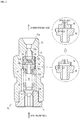
delivery valve 10 will be described with reference toFig. 2 . -
Fig. 2 illustrates thedelivery valve 10 in partially sectional view and side view. On the upper right side ofFig. 2 , the configuration of a conventional valve element and a conventional receiving element, and the configuration of avalve element 15 and areceiving element 16 of the present embodiment are enlarged and compared. - The
delivery valve 10 is provided with a tubulardelivery valve case 11, adelivery valve body 13, and a delivery valve spring 14 which biases thedelivery valve body 13 toward thedelivery valve case 11. - The
delivery valve case 11 and theplunger barrel 103 are inserted into the hole which is formed on thepump housing 102 from the upper face toward the lower side thereof (refer toFig. 1 ). Thedelivery valve body 13 is vertically slidably inserted into the lower part of aspring housing section 12d of acasing 12 and biased toward the delivery valve case 11 (downward) by the delivery valve spring 14. A space formed by thereceiving element 16, thespring housing section 12d, and thedelivery valve body 13 is referred to as a delivery chamber R. - The
casing 12 is a tubular member and inserted from the upper side of thefuel injection pump 100 into the hole which is formed on thepump housing 102 on the upper face thereof. A through hole is formed on an axial part of thecasing 12. Afuel discharge port 12a, a small-diameter fuel passage 12b, a guidebody housing section 12c, thespring housing section 12d, and a delivery valve casefitting section 12e are formed inside the through hole of thecasing 12 in this order from the upper side. - The
fuel discharge port 12a is formed in a tapered shape expanding toward the downstream side on a downstream end of the through hole, and a high-pressure tube is connected to thefuel discharge port 12a. The small-diameter fuel passage 12b is formed under (on the upstream side of) thefuel discharge port 12a to receive one side of a dampingvalve spring 18. The guidebody housing section 12c is formed on the upstream side of the small-diameter fuel passage 12b to house aguide body 19 and a dampingvalve 17. - The damping
valve 17 includes thevalve element 15 and the receivingelement 16. The dampingvalve 17 is configured in such a manner that thevalve element 15 is biased downward (toward the upstream side) by the dampingvalve spring 18 so as to abut against the receivingelement 16. - The
valve element 15 faces the receivingelement 16. Thevalve element 15 is formed in a two-stage cylindrical shape and has anorifice 15a which vertically penetrates an axial part thereof. Thevalve element 15 has acylindrical recess 15b which is recessed upward from the center of a face of thevalve element 15, the face facing the receivingelement 16. Therecess 15b communicates with theorifice 15a. Therecess 15b is formed in a cylindrical shape. The receivingelement 16 is formed in a two-stage cylindrical shape and has apassage hole 16a which vertically penetrates an axial part thereof. - The
spring housing section 12d is formed on the upstream side of the guidebody housing section 12c to house the delivery valve spring 14 and the upper part of thedelivery valve body 13. The delivery valve casefitting section 12e which is fitted with the upper part of thedelivery valve case 11 is formed under thespring housing section 12d. - The action of the
delivery valve 10 will be described. - When the pressure of the pressurized fuel inside the pressure chamber 107 (refer to
Fig. 1 ) exceeds a predetermined opening pressure for thedelivery valve 10 and the dampingvalve 17, thedelivery valve body 13 and thevalve element 15 slide toward the downstream side (upward) to open thedelivery valve 10 and the dampingvalve 17. Accordingly, the fuel is pressure-fed to a fuel injection nozzle (not illustrated) through thespring housing section 12d, thepassage hole 16a, the small-diameter fuel passage 12b, and thefuel discharge port 12a. - At this time, the resistance of the fuel flowing between the
valve element 15 and the receivingelement 16 immediately after the lift of the valve element 15 (in the first half of the fuel injection) is similar to that in a conventional configuration due to a small gap between thevalve element 15 and the receivingelement 16 even when therecess 15b is formed. However, when the lift of thevalve element 15 exceeds a predetermined lift amount (in the second half of the fuel injection), therecess 15b sufficiently reduces a distance having the minimum fuel passage width (the minimum gap between thevalve element 15 and the receiving element 16) from a conventional distance L2 to a distance L1. Thus, the fuel injection amount is increased. - When this phenomenon is considered based on a fuel injection rate (a fuel injection amount per unit time), the fuel injection rate decreases in the first half of the fuel injection and increases in the second half of the fuel injection. That is, an initial injection rate of the diesel engine is reduced.
- An effect of the
delivery valve 10 will be described. - The
delivery valve 10 makes it possible to reduce the initial injection rate of thefuel injection pump 100 and thereby significantly reduce white smoke in exhaust gas of the diesel engine. - The configuration of a
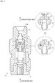
delivery valve 20 will be described with reference toFig. 3 . -
Fig. 3 illustrates thedelivery valve 20 in partially sectional view and side view. On the upper right side ofFig. 3 , the configuration of a conventional valve element and a conventional receiving element, and the configuration of avalve element 25 and a receivingelement 26 of the present embodiment are enlarged and compared. - The
delivery valve 20 relates to Embodiment 2 of the fuel injection pump of the present invention. Adelivery valve case 21, acasing 22, adelivery valve body 23, adelivery valve spring 24, a dampingvalve spring 28, and aguide body 29 of thedelivery valve 20 respectively have configurations similar to the configurations of thedelivery valve case 11, thecasing 12, thedelivery valve body 13, the delivery valve spring 14, the dampingvalve spring 18, and theguide body 19 of thedelivery valve 10. Thus, description thereof will not be provided. - A damping
valve 27 includes thevalve element 25 and the receivingelement 26. The dampingvalve 27 is configured in such a manner that thevalve element 25 is biased downward (toward the upstream side) by the dampingvalve spring 28 so as to abut against the receivingelement 26. - The
valve element 25 is formed in a two-stage cylindrical shape and has anorifice 25a which vertically penetrates an axial part thereof. The receivingelement 26 is formed in a two-stage cylindrical shape and has apassage hole 26a which vertically penetrates an axial part thereof. The receivingelement 26 has acylindrical recess 26b which is recessed downward from the center of a face of the receivingelement 26, the face facing thevalve element 25. Therecess 26b communicates with theorifice 25a. Therecess 26b is formed in a cylindrical shape. - The action of the
delivery valve 20 will be described. - When the pressure of the pressurized fuel inside the
pressure chamber 107 exceeds a predetermined opening pressure for thedelivery valve 20 and the dampingvalve 27, thedelivery valve body 23 and thevalve element 25 slide toward the downstream side (upward) to open thedelivery valve 20 and the dampingvalve 27. Accordingly, the fuel is pressure-fed to a fuel injection nozzle (not illustrated) through aspring housing section 22d, thepassage hole 26a, a small-diameter fuel passage 22b, and afuel discharge port 22a. - At this time, the resistance of the fuel flowing between the
valve element 25 and the receivingelement 26 immediately after the lift of the valve element 25 (in the first half of the fuel injection) is similar to that in a conventional configuration due to a small gap between thevalve element 25 and the receivingelement 26 even when therecess 26b is formed. However, when the lift of thevalve element 25 exceeds a predetermined lift amount (in the second half of the fuel injection), therecess 26b sufficiently reduces a distance having the minimum fuel passage width (the minimum gap between thevalve element 25 and the receiving element 26) from a conventional distance L2 to a distance L1. Thus, the fuel injection amount is increased. - When this phenomenon is considered based on a fuel injection rate (a fuel injection amount per unit time), the fuel injection rate decreases in the first half of the fuel injection, and the fuel injection rate increases in the second half of the fuel injection. That is, an initial injection rate of the diesel engine is reduced.
- An effect of the
delivery valve 20 will be described. - The
delivery valve 20 makes it possible to reduce the initial injection rate of thefuel injection pump 100 and thereby significantly reduce white smoke in exhaust gas of the diesel engine. - The configuration of a
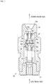
delivery valve 30 will be described with reference toFig. 4 . -
Fig. 4 illustrates thedelivery valve 30 in partially sectional view and side view. - The
delivery valve 30 relates to Embodiment 3 of the fuel injection pump of the present invention. Adelivery valve case 31, acasing 32, adelivery valve body 33, and adelivery valve spring 34 of thedelivery valve 30 respectively have configurations similar to the configurations of thedelivery valve case 11, thecasing 12, thedelivery valve body 13, and the delivery valve spring 14 of thedelivery valve 10. Thus, description thereof will not be provided. - A damping
valve 37 includes aninner valve element 35i, an outer valve element 35o, a receivingelement 36, and asupport 39. Theinner valve element 35i is biased downward (toward the upstream side) from thesupport 39 by an inner dampingvalve spring 38i so as to abut against the receivingelement 36. The outer valve element 35o is biased downward (toward the upstream side) from thecasing 32 by an outer damping valve spring 38o so as to abut against the receivingelement 36. - The
inner valve element 35i is formed in a two-stage cylindrical shape and has anorifice 35a which vertically penetrates an axial part thereof. The outer valve element 35o is formed in an annular shape. The receivingelement 36 is formed in a two-stage cylindrical shape and has apassage hole 36a which vertically penetrates an axial part thereof. Thesupport 39 is formed in a two-stage cylindrical shape and has apassage hole 39a which vertically penetrates an axial part thereof. - The outer valve element 35o is engaged with a stepped part of the
inner valve element 35i. That is, a biasing force of the outer damping valve spring 38o and a biasing force of the inner dampingvalve spring 38i are applied to theinner valve element 35i. - The action of the
delivery valve 30 will be described with reference toFigs. 5(A) to 5(C) . -
Figs. 5(A) to 5(C) illustrate thedelivery valve 30 in partially sectional view and side view. - As shown in
Fig. 5(A) , when the pressure of the pressurized fuel inside thepressure chamber 107 exceeds a predetermined opening pressure for the dampingvalve 37, the fuel pressure-fed through thepassage hole 36a of the receivingelement 36 overcomes the biasing forces of the inner dampingvalve spring 38i and the outer damping valve spring 38o, so that theinner valve element 35i and the outer valve element 35o are lifted toward the downstream side (upward) (in the first half of the fuel injection). At this time, theinner valve element 35i and the outer valve element 35o receive resistance produced by the biasing forces of the inner dampingvalve spring 38i and the outer damping valve spring 38o. - As shown in
Fig. 5(B) , when theinner valve element 35i and the outer valve element 35o are further lifted toward the downstream side (upward), the upper end face of theinner valve element 35i comes into contact with the lower end face of thesupport 39. - As shown in
Fig. 5(C) , when the upper end face of theinner valve element 35i comes into contact with the lower end face of thesupport 39, the outer valve element 35o is separated from theinner valve element 35i and lifted toward the downstream side (upward) (in the second half of the fuel injection). At this point, since the outer valve element 35o receives resistance produced only by the biasing force of the outer damping valve spring 38o, the lift amount increases. Thus, the fuel injection amount becomes larger than that in the first half of the fuel injection. - When this phenomenon is considered based on a fuel injection rate (a fuel injection amount per unit time), the fuel injection rate decreases in the first half of the fuel injection, and the fuel injection rate increases in the second half of the fuel injection. That is, an initial injection rate of the diesel engine is reduced.
- An effect of the
delivery valve 30 will be described. - The
delivery valve 30 makes it possible to reduce the initial injection rate of thefuel injection pump 100 and thereby significantly reduce white smoke in exhaust gas of the diesel engine. - The configuration of a
fuel injection pump 400 will be described with reference toFig. 6 . -
Fig. 6 schematically illustrates thefuel injection pump 400. - The
fuel injection pump 400 relates to Embodiment 4 of the fuel injection pump of the present invention. Thefuel injection pump 400 is similar to thefuel injection pump 100 according toEmbodiment 1 except for a part particularly described below. - A
recess 408a is formed on the lower face of atappet 408. There is not a roller between therecess 408a and the lower face of atappet 408. Therecess 408a is formed in a circular arc shape when viewed from a direction perpendicular to acam shaft 410. Therecess 408a varies a contact position between acam 409 and therecess 408a depending on the shape of thecam 409. Thus, the timing and amount of vertical reciprocating slide of aplunger 404 caused by thecam 409 are varied. That is, the fuel injection amount can be varied without changing the profile of thecam 409. Therecess 408a is formed so that the fuel injection amount increases in the second half of fuel injection. - Such a configuration enables an initial injection rate of the diesel engine to be reduced. That is, it is possible to reduce the initial injection rate of the
fuel injection pump 400 and thereby significantly reduce white smoke in exhaust gas of the diesel engine. - The configuration of a
fuel injection pump 500 will be described with reference toFig. 7 . -
Fig. 7 illustrates thefuel injection pump 500 in partially sectional view and side view. - The
fuel injection pump 500 relates to Embodiment 5 of the fuel injection pump of the present invention. Thefuel injection pump 500 is similar to thefuel injection pump 100 according toEmbodiment 1 except for a part particularly described below. - A
capacity addition mechanism 510 communicates with a delivery chamber R. The capacity of thecapacity addition mechanism 510 decreases as the engine speed increases and increases as the engine speed decreases. Thecapacity addition mechanism 510 is provided with apassage 511, acylinder chamber 512, afuel chamber 512a, apiston 513, asolenoid 514, and acontroller 550. - The
cylinder chamber 512 forms thefuel chamber 512a by thepiston 513. Thepassage 511 allows the delivery chamber R formed on a casing and thefuel chamber 512a to communicate with each other. Thepiston 513 slides inside thecylinder chamber 512 to increase or reduce the capacity of thefuel chamber 512a. Thesolenoid 514 is connected to thecontroller 550 to drive thepiston 513 to reciprocate. - The
controller 550 is connected to thesolenoid 514 and anengine speed senor 551 which detects the engine speed of an engine (not illustrated) provided with thefuel injection pump 500. Thecontroller 550 has a function of controlling thesolenoid 514 to drive thepiston 513 so as to reduce the capacity of thecylinder chamber 512 as the engine speed increases and controlling thesolenoid 514 to drive thepiston 513 so as to increase the capacity of thecylinder chamber 512 as the engine speed decreases. - The action of the
capacity addition mechanism 510 will be described. - With the
capacity addition mechanism 510, the capacity of thecylinder chamber 512 of thecapacity addition mechanism 510 is added to the capacity of the conventional delivery chamber R. Thus, a time lag occurs when the injection pressure is transmitted to a fuel injection nozzle (not illustrated) to delay a fuel injection timing. That is, providing thecapacity addition mechanism 510 delays the fuel injection timing over the entire engine speed (first control). - On the other hand, in the
capacity addition mechanism 510, the capacity of thecylinder chamber 512 is reduced as the engine speed increases. Thus, although the fuel injection timing is delayed over the entire engine speed by the first control, the time lag is eliminated before the injection pressure is transmitted to the fuel injection nozzle (not illustrated) to advance the fuel injection timing. That is, the fuel injection timing is advanced compared to that during the first control only when the engine speed is high (second control). - An effect of the
capacity addition mechanism 510 will be described. - The
capacity addition mechanism 510 enables the generation of Sd and deterioration in a white smoke disappearance time to be improved. That is, since the fuel injection timing is delayed over the entire engine speed by the first control and advanced by the second control only when the engine speed is high, the generation of Sd and the deterioration in the white smoke disappearance time can be improved. - The configuration of a
fuel injection pump 600 will be described with reference toFig. 8 . -
Fig. 8 illustrates thefuel injection pump 600 in partially sectional view and side view. - The
fuel injection pump 600 relates to Embodiment 6 of the fuel injection pump of the present invention. Thefuel injection pump 600 is similar to thefuel injection pump 100 according toEmbodiment 1 except for a part particularly described below. - A
capacity addition mechanism 620 communicates with a delivery chamber R. The capacity of thecapacity addition mechanism 620 decreases as the engine speed increases and increases as the engine speed decreases. Thecapacity addition mechanism 620 is provided with apassage 621, acylinder chamber 622, apiston 623, a switchingvalve 624, and ahydraulic pump 625. - The
passage 621, thecylinder chamber 622, afuel chamber 622a, and thepiston 623 respectively have configurations similar to the configurations of thepassage 511, thecylinder chamber 512, and thepiston 513 of Embodiment 5. Thus, description thereof will not be provided. - The
cylinder chamber 622 is divided into thefuel chamber 622a and an operatingoil chamber 622b by thepiston 623. The switchingvalve 624 is disposed between thehydraulic pump 625 and thecylinder chamber 622. The switchingvalve 624 has a function of supplying an operating oil to the operatingoil chamber 622b of thecylinder chamber 622 when the pressure of the operating oil fed from thehydraulic pump 625 becomes a predetermined pressure or more. Thehydraulic pump 625 is driven by an engine provided with thefuel injection pump 600. - The action of the
capacity addition mechanism 620 will be described. - With the
capacity addition mechanism 620, the capacity of thecylinder chamber 622 of thecapacity addition mechanism 620 is added to the capacity of the conventional delivery chamber R. Thus, a time lag occurs when the injection pressure is transmitted to a fuel injection nozzle (not illustrated) to delay a fuel injection timing. That is, providing thecapacity addition mechanism 620 delays the fuel injection timing over the entire engine speed (first control). - On the other hand, in the
capacity addition mechanism 620, when the operating pressure by thehydraulic pump 625 increases to a predetermined pressure or more as the engine speed increases, the switchingvalve 624 is switched to supply the operating oil to the operating oil chamber 62b. Accordingly, thepiston 623 inside thecylinder chamber 622 moves toward thefuel chamber 622a to reduce the capacity of thefuel chamber 622a. Thus, although the fuel injection timing is delayed over the entire engine speed by the first control, the time lag is eliminated before the injection pressure is transmitted to the fuel injection nozzle (not illustrated) to advance the fuel injection timing. That is, the fuel injection timing is advanced compared to that during the first control only when the engine speed is high (second control). - An effect of the
capacity addition mechanism 620 will be described. - The
capacity addition mechanism 620 enables the generation of Sd and deterioration in a white smoke disappearance time to be improved. That is, since the fuel injection timing is delayed over the entire engine speed by the first control and advanced by the second control only when the engine speed is high, the generation of Sd and the deterioration in the white smoke disappearance time can be improved. - The configuration of a
fuel injection pump 700 will be described with reference toFig. 9 . -
Fig. 9 illustrates thefuel injection pump 700 in partially sectional view and side view. - The
fuel injection pump 700 relates to Embodiment 7 of the fuel injection pump of the present invention. Thefuel injection pump 700 is similar to thefuel injection pump 100 according toEmbodiment 1 except for a part particularly described below. - A
capacity addition mechanism 730 communicates with a delivery chamber R. The capacity of thecapacity addition mechanism 730 decreases as the engine speed increases and increases as the engine speed decreases. Thecapacity addition mechanism 730 is provided with apassage 731, acylinder chamber 732, apiston 733, and asynchronous link 734. - The
passage 731, thecylinder chamber 732, acombustion chamber 732a, and thepiston 733 respectively have configurations similar to the configurations of thepassage 511, thecylinder chamber 512, thecombustion chamber 512a, and thepiston 513 of Embodiment 5. Thus, description thereof will not be provided. - A
regulator lever 752 is disposed on an engine provided with thefuel injection pump 700. Theregulator lever 752 is operated to turn to adjust the fuel injection amount of thefuel injection pump 100 to control the engine speed. - One end of the
synchronous link 734 is turnably supported on the other end side of thepiston 733, and the other end of thesynchronous link 734 is turnably supported on one end side of theregulator lever 752. Thesynchronous link 734 supports thepiston 733 and theregulator valve 752 so as to reduce the capacity of thecylinder chamber 732 when theregulator lever 752 is turned to control the engine speed at a high speed and increase the capacity of thecylinder chamber 732 when theregulator lever 752 is turned to control the engine speed at a low speed. - The action of the
capacity addition mechanism 730 will be described. - With the
capacity addition mechanism 730, the capacity of thecylinder chamber 732 of thecapacity addition mechanism 730 is added to the capacity of the conventional delivery chamber R. Thus, a time lag occurs when the injection pressure is transmitted to a fuel injection nozzle (not illustrated) to delay a fuel injection timing. That is, providing the capacity addition mechanism 720 delays the fuel injection timing over the entire engine speed (first control). - On the other hand, in the
capacity addition mechanism 730, the capacity of thecylinder chamber 732 is reduced by turning theregulator lever 752 so as to increase the engine speed. Thus, although the fuel injection timing is delayed over the entire engine speed by the first control, the time lag is eliminated before the injection pressure is transmitted to the fuel injection nozzle (not illustrated) to advance the fuel injection timing. That is, the fuel injection timing is advanced compared to that during the first control only when the engine speed is high (second control). - An effect of the
capacity addition mechanism 730 will be described. - The
capacity addition mechanism 730 enables the generation of Sd and deterioration in a white smoke disappearance time to be improved. That is, since the fuel injection timing is delayed over the entire engine speed by the first control and advanced by the second control only when the engine speed is high, the generation of Sd and the deterioration in the white smoke disappearance time can be improved. - The present invention is applicable to a fuel injection pump.
-
- 10: Delivery valve
- 15: Valve element
- 15a: Orifice
- 15b: Recess
- 16: Receiving element
- 16a: Passage hole
- 17: Damping valve
- 100: Fuel injection pump
Claims (4)
- A fuel injection pump configured to deliver, at high pressure, a fuel to be injected into a combustion chamber of a diesel engine, the fuel injection pump comprising:a delivery valve disposed in the middle of a path for pressure-feeding the fuel from a plunger to a fuel injection nozzle; anda damping valve disposed on a downstream side of the delivery valve, the damping valve comprisinga valve element having an orifice formed on an axial part of the valve element, the valve element being biased toward an upstream side by a damping valve spring, anda receiving element having a passage hole formed on an axial part of the receiving element, the receiving element being configured to abut against the valve element,wherein a recess communicating with the passage hole is formed on a face of the valve element, the face facing the receiving element.
- The fuel injection pump according to claim 1, wherein the recess is formed in a cylindrical shape.
- A fuel injection pump configured to deliver, at high pressure, a fuel to be injected into a combustion chamber of a diesel engine, the fuel injection pump comprising:a delivery valve disposed in the middle of a path for pressure-feeding the fuel from a plunger to a fuel injection nozzle; anda damping valve disposed on a downstream side of the delivery valve, the damping valve comprisinga valve element having an orifice formed on an axial part of the valve element, the valve element being biased toward an upstream side by a damping valve spring, anda receiving element having a passage hole formed on an axial part of the receiving element, the receiving element being configured to abut against the valve element,wherein a recess communicating with the passage hole is formed on a face of the receiving element, the face facing the valve element.
- The fuel injection pump according to claim 3, wherein the recess is formed in a cylindrical shape.
Applications Claiming Priority (3)
| Application Number | Priority Date | Filing Date | Title |
|---|---|---|---|
| JP2013204726A JP2015068295A (en) | 2013-09-30 | 2013-09-30 | Fuel injection pump |
| JP2013204725A JP2015068294A (en) | 2013-09-30 | 2013-09-30 | Fuel injection pump |
| PCT/JP2014/069646 WO2015045600A1 (en) | 2013-09-30 | 2014-07-25 | Fuel injection pump |
Publications (2)
| Publication Number | Publication Date |
|---|---|
| EP3054148A1 true EP3054148A1 (en) | 2016-08-10 |
| EP3054148A4 EP3054148A4 (en) | 2017-06-07 |
Family
ID=52742757
Family Applications (1)
| Application Number | Title | Priority Date | Filing Date |
|---|---|---|---|
| EP14848563.4A Withdrawn EP3054148A4 (en) | 2013-09-30 | 2014-07-25 | Fuel injection pump |
Country Status (5)
| Country | Link |
|---|---|
| US (1) | US20160230727A1 (en) |
| EP (1) | EP3054148A4 (en) |
| KR (1) | KR20160060756A (en) |
| CN (1) | CN105593511A (en) |
| WO (1) | WO2015045600A1 (en) |
Families Citing this family (1)
| Publication number | Priority date | Publication date | Assignee | Title |
|---|---|---|---|---|
| DE102017220328A1 (en) * | 2017-11-15 | 2019-05-16 | Robert Bosch Gmbh | Vibration damping arrangement for injection systems of motor vehicles, in particular for fuel injection systems, and injection system with such a vibration damping arrangement |
Family Cites Families (11)
| Publication number | Priority date | Publication date | Assignee | Title |
|---|---|---|---|---|
| JPS58119963A (en) * | 1982-01-11 | 1983-07-16 | Nippon Denso Co Ltd | Fuel injection pump |
| JPS61152961A (en) * | 1984-12-25 | 1986-07-11 | Hino Motors Ltd | Fuel injection device for diesel engine |
| JPH0526302Y2 (en) * | 1988-08-12 | 1993-07-02 | ||
| GB2252145A (en) * | 1991-01-22 | 1992-07-29 | Lucas Ind Plc | Valve for fuel pumping apparatus |
| JPH0526302A (en) * | 1991-07-24 | 1993-02-02 | Bridgestone Cycle Co | Speed change gear |
| JPH05180117A (en) * | 1991-12-27 | 1993-07-20 | Nippondenso Co Ltd | Fuel injection device |
| JPH0849633A (en) * | 1994-08-08 | 1996-02-20 | Nippondenso Co Ltd | Discharge valve for fuel injection device |
| GB9713335D0 (en) * | 1997-06-24 | 1997-08-27 | Ricardo Consulting Eng | Fuel injection systems for diesel engines |
| CN2876358Y (en) * | 2005-11-28 | 2007-03-07 | 潍柴动力股份有限公司 | Oil outlet valve used on diesel oil engine oil spray pump |
| JP2009275596A (en) * | 2008-05-14 | 2009-11-26 | Yanmar Co Ltd | Damping valve of fuel injector |
| CN202991314U (en) * | 2012-12-04 | 2013-06-12 | 中国第一汽车股份有限公司无锡油泵油嘴研究所 | Split type damping fuel outlet valve |
-
2014
- 2014-07-25 WO PCT/JP2014/069646 patent/WO2015045600A1/en not_active Ceased
- 2014-07-25 EP EP14848563.4A patent/EP3054148A4/en not_active Withdrawn
- 2014-07-25 CN CN201480053583.2A patent/CN105593511A/en active Pending
- 2014-07-25 KR KR1020167011058A patent/KR20160060756A/en not_active Ceased
- 2014-07-25 US US15/024,987 patent/US20160230727A1/en not_active Abandoned
Also Published As
| Publication number | Publication date |
|---|---|
| KR20160060756A (en) | 2016-05-30 |
| US20160230727A1 (en) | 2016-08-11 |
| WO2015045600A1 (en) | 2015-04-02 |
| EP3054148A4 (en) | 2017-06-07 |
| CN105593511A (en) | 2016-05-18 |
Similar Documents
| Publication | Publication Date | Title |
|---|---|---|
| JP4701227B2 (en) | Plunger high pressure fuel pump | |
| EP3135900B1 (en) | High-pressure fuel supply pump | |
| US10890177B2 (en) | Fuel pump for pressurizing low pressure fuel suctioned into a pressurizing chamber and discharging high pressure fuel pressurized in the pressurizing chamber | |
| EP2038535B1 (en) | Fuel supply apparatus and fuel supply method of an internal combustion engine | |
| US7509947B2 (en) | Fuel injection pump | |
| US20160230727A1 (en) | Fuel injection pump | |
| US9200602B2 (en) | Pressure regulator | |
| JP2014105668A (en) | High pressure fuel supply pump | |
| JP2017101621A (en) | Relief valve device and high-pressure pump using the same | |
| JP2015137578A (en) | High pressure pump | |
| JP4241611B2 (en) | Valve device for fuel injection pump | |
| JP5285442B2 (en) | Fuel injection pump | |
| WO2013129592A1 (en) | Fuel injection pump | |
| JP4483954B2 (en) | pump | |
| JP2008106620A (en) | pump | |
| JP2015068294A (en) | Fuel injection pump | |
| JP4998448B2 (en) | Pressure limiter for fuel injection system | |
| JP2015068295A (en) | Fuel injection pump | |
| JP5795017B2 (en) | Fuel injection pump | |
| JP6575439B2 (en) | Fuel pressure control device for internal combustion engine | |
| KR20070020074A (en) | High pressure pumps for fuel injectors in engines | |
| US20150041566A1 (en) | Apparatus for controlling needle valve leakage | |
| JP2017008806A (en) | High pressure pump | |
| JP2010190081A (en) | Vane pump | |
| KR20140126768A (en) | Hydraulic-drive fuel injection device and internal combustion engine |
Legal Events
| Date | Code | Title | Description |
|---|---|---|---|
| PUAI | Public reference made under article 153(3) epc to a published international application that has entered the european phase |
Free format text: ORIGINAL CODE: 0009012 |
|
| 17P | Request for examination filed |
Effective date: 20160502 |
|
| AK | Designated contracting states |
Kind code of ref document: A1 Designated state(s): AL AT BE BG CH CY CZ DE DK EE ES FI FR GB GR HR HU IE IS IT LI LT LU LV MC MK MT NL NO PL PT RO RS SE SI SK SM TR |
|
| AX | Request for extension of the european patent |
Extension state: BA ME |
|
| DAX | Request for extension of the european patent (deleted) | ||
| A4 | Supplementary search report drawn up and despatched |
Effective date: 20170509 |
|
| RIC1 | Information provided on ipc code assigned before grant |
Ipc: F02M 59/46 20060101AFI20170502BHEP Ipc: F02M 55/04 20060101ALI20170502BHEP |
|
| STAA | Information on the status of an ep patent application or granted ep patent |
Free format text: STATUS: REQUEST FOR EXAMINATION WAS MADE |
|
| STAA | Information on the status of an ep patent application or granted ep patent |
Free format text: STATUS: THE APPLICATION IS DEEMED TO BE WITHDRAWN |
|
| 18D | Application deemed to be withdrawn |
Effective date: 20171209 |