EP3054109A1 - Method for producing member for fluid machines, and member for fluid machines - Google Patents
Method for producing member for fluid machines, and member for fluid machines Download PDFInfo
- Publication number
- EP3054109A1 EP3054109A1 EP14846780.6A EP14846780A EP3054109A1 EP 3054109 A1 EP3054109 A1 EP 3054109A1 EP 14846780 A EP14846780 A EP 14846780A EP 3054109 A1 EP3054109 A1 EP 3054109A1
- Authority
- EP
- European Patent Office
- Prior art keywords
- base
- glass
- based material
- fluid machines
- coating
- Prior art date
- Legal status (The legal status is an assumption and is not a legal conclusion. Google has not performed a legal analysis and makes no representation as to the accuracy of the status listed.)
- Withdrawn
Links
Images


Classifications
-
- F—MECHANICAL ENGINEERING; LIGHTING; HEATING; WEAPONS; BLASTING
- F04—POSITIVE - DISPLACEMENT MACHINES FOR LIQUIDS; PUMPS FOR LIQUIDS OR ELASTIC FLUIDS
- F04D—NON-POSITIVE-DISPLACEMENT PUMPS
- F04D29/00—Details, component parts, or accessories
- F04D29/02—Selection of particular materials
- F04D29/023—Selection of particular materials especially adapted for elastic fluid pumps
-
- C—CHEMISTRY; METALLURGY
- C23—COATING METALLIC MATERIAL; COATING MATERIAL WITH METALLIC MATERIAL; CHEMICAL SURFACE TREATMENT; DIFFUSION TREATMENT OF METALLIC MATERIAL; COATING BY VACUUM EVAPORATION, BY SPUTTERING, BY ION IMPLANTATION OR BY CHEMICAL VAPOUR DEPOSITION, IN GENERAL; INHIBITING CORROSION OF METALLIC MATERIAL OR INCRUSTATION IN GENERAL
- C23C—COATING METALLIC MATERIAL; COATING MATERIAL WITH METALLIC MATERIAL; SURFACE TREATMENT OF METALLIC MATERIAL BY DIFFUSION INTO THE SURFACE, BY CHEMICAL CONVERSION OR SUBSTITUTION; COATING BY VACUUM EVAPORATION, BY SPUTTERING, BY ION IMPLANTATION OR BY CHEMICAL VAPOUR DEPOSITION, IN GENERAL
- C23C18/00—Chemical coating by decomposition of either liquid compounds or solutions of the coating forming compounds, without leaving reaction products of surface material in the coating; Contact plating
- C23C18/16—Chemical coating by decomposition of either liquid compounds or solutions of the coating forming compounds, without leaving reaction products of surface material in the coating; Contact plating by reduction or substitution, e.g. electroless plating
- C23C18/31—Coating with metals
- C23C18/32—Coating with nickel, cobalt or mixtures thereof with phosphorus or boron
-
- C—CHEMISTRY; METALLURGY
- C23—COATING METALLIC MATERIAL; COATING MATERIAL WITH METALLIC MATERIAL; CHEMICAL SURFACE TREATMENT; DIFFUSION TREATMENT OF METALLIC MATERIAL; COATING BY VACUUM EVAPORATION, BY SPUTTERING, BY ION IMPLANTATION OR BY CHEMICAL VAPOUR DEPOSITION, IN GENERAL; INHIBITING CORROSION OF METALLIC MATERIAL OR INCRUSTATION IN GENERAL
- C23C—COATING METALLIC MATERIAL; COATING MATERIAL WITH METALLIC MATERIAL; SURFACE TREATMENT OF METALLIC MATERIAL BY DIFFUSION INTO THE SURFACE, BY CHEMICAL CONVERSION OR SUBSTITUTION; COATING BY VACUUM EVAPORATION, BY SPUTTERING, BY ION IMPLANTATION OR BY CHEMICAL VAPOUR DEPOSITION, IN GENERAL
- C23C28/00—Coating for obtaining at least two superposed coatings either by methods not provided for in a single one of groups C23C2/00 - C23C26/00 or by combinations of methods provided for in subclasses C23C and C25C or C25D
- C23C28/04—Coating for obtaining at least two superposed coatings either by methods not provided for in a single one of groups C23C2/00 - C23C26/00 or by combinations of methods provided for in subclasses C23C and C25C or C25D only coatings of inorganic non-metallic material
-
- C—CHEMISTRY; METALLURGY
- C23—COATING METALLIC MATERIAL; COATING MATERIAL WITH METALLIC MATERIAL; CHEMICAL SURFACE TREATMENT; DIFFUSION TREATMENT OF METALLIC MATERIAL; COATING BY VACUUM EVAPORATION, BY SPUTTERING, BY ION IMPLANTATION OR BY CHEMICAL VAPOUR DEPOSITION, IN GENERAL; INHIBITING CORROSION OF METALLIC MATERIAL OR INCRUSTATION IN GENERAL
- C23C—COATING METALLIC MATERIAL; COATING MATERIAL WITH METALLIC MATERIAL; SURFACE TREATMENT OF METALLIC MATERIAL BY DIFFUSION INTO THE SURFACE, BY CHEMICAL CONVERSION OR SUBSTITUTION; COATING BY VACUUM EVAPORATION, BY SPUTTERING, BY ION IMPLANTATION OR BY CHEMICAL VAPOUR DEPOSITION, IN GENERAL
- C23C28/00—Coating for obtaining at least two superposed coatings either by methods not provided for in a single one of groups C23C2/00 - C23C26/00 or by combinations of methods provided for in subclasses C23C and C25C or C25D
- C23C28/30—Coatings combining at least one metallic layer and at least one inorganic non-metallic layer
- C23C28/32—Coatings combining at least one metallic layer and at least one inorganic non-metallic layer including at least one pure metallic layer
- C23C28/322—Coatings combining at least one metallic layer and at least one inorganic non-metallic layer including at least one pure metallic layer only coatings of metal elements only
-
- C—CHEMISTRY; METALLURGY
- C23—COATING METALLIC MATERIAL; COATING MATERIAL WITH METALLIC MATERIAL; CHEMICAL SURFACE TREATMENT; DIFFUSION TREATMENT OF METALLIC MATERIAL; COATING BY VACUUM EVAPORATION, BY SPUTTERING, BY ION IMPLANTATION OR BY CHEMICAL VAPOUR DEPOSITION, IN GENERAL; INHIBITING CORROSION OF METALLIC MATERIAL OR INCRUSTATION IN GENERAL
- C23C—COATING METALLIC MATERIAL; COATING MATERIAL WITH METALLIC MATERIAL; SURFACE TREATMENT OF METALLIC MATERIAL BY DIFFUSION INTO THE SURFACE, BY CHEMICAL CONVERSION OR SUBSTITUTION; COATING BY VACUUM EVAPORATION, BY SPUTTERING, BY ION IMPLANTATION OR BY CHEMICAL VAPOUR DEPOSITION, IN GENERAL
- C23C28/00—Coating for obtaining at least two superposed coatings either by methods not provided for in a single one of groups C23C2/00 - C23C26/00 or by combinations of methods provided for in subclasses C23C and C25C or C25D
- C23C28/30—Coatings combining at least one metallic layer and at least one inorganic non-metallic layer
- C23C28/34—Coatings combining at least one metallic layer and at least one inorganic non-metallic layer including at least one inorganic non-metallic material layer, e.g. metal carbide, nitride, boride, silicide layer and their mixtures, enamels, phosphates and sulphates
- C23C28/345—Coatings combining at least one metallic layer and at least one inorganic non-metallic layer including at least one inorganic non-metallic material layer, e.g. metal carbide, nitride, boride, silicide layer and their mixtures, enamels, phosphates and sulphates with at least one oxide layer
-
- C—CHEMISTRY; METALLURGY
- C23—COATING METALLIC MATERIAL; COATING MATERIAL WITH METALLIC MATERIAL; CHEMICAL SURFACE TREATMENT; DIFFUSION TREATMENT OF METALLIC MATERIAL; COATING BY VACUUM EVAPORATION, BY SPUTTERING, BY ION IMPLANTATION OR BY CHEMICAL VAPOUR DEPOSITION, IN GENERAL; INHIBITING CORROSION OF METALLIC MATERIAL OR INCRUSTATION IN GENERAL
- C23C—COATING METALLIC MATERIAL; COATING MATERIAL WITH METALLIC MATERIAL; SURFACE TREATMENT OF METALLIC MATERIAL BY DIFFUSION INTO THE SURFACE, BY CHEMICAL CONVERSION OR SUBSTITUTION; COATING BY VACUUM EVAPORATION, BY SPUTTERING, BY ION IMPLANTATION OR BY CHEMICAL VAPOUR DEPOSITION, IN GENERAL
- C23C8/00—Solid state diffusion of only non-metal elements into metallic material surfaces; Chemical surface treatment of metallic material by reaction of the surface with a reactive gas, leaving reaction products of surface material in the coating, e.g. conversion coatings, passivation of metals
- C23C8/02—Pretreatment of the material to be coated
-
- C—CHEMISTRY; METALLURGY
- C23—COATING METALLIC MATERIAL; COATING MATERIAL WITH METALLIC MATERIAL; CHEMICAL SURFACE TREATMENT; DIFFUSION TREATMENT OF METALLIC MATERIAL; COATING BY VACUUM EVAPORATION, BY SPUTTERING, BY ION IMPLANTATION OR BY CHEMICAL VAPOUR DEPOSITION, IN GENERAL; INHIBITING CORROSION OF METALLIC MATERIAL OR INCRUSTATION IN GENERAL
- C23C—COATING METALLIC MATERIAL; COATING MATERIAL WITH METALLIC MATERIAL; SURFACE TREATMENT OF METALLIC MATERIAL BY DIFFUSION INTO THE SURFACE, BY CHEMICAL CONVERSION OR SUBSTITUTION; COATING BY VACUUM EVAPORATION, BY SPUTTERING, BY ION IMPLANTATION OR BY CHEMICAL VAPOUR DEPOSITION, IN GENERAL
- C23C8/00—Solid state diffusion of only non-metal elements into metallic material surfaces; Chemical surface treatment of metallic material by reaction of the surface with a reactive gas, leaving reaction products of surface material in the coating, e.g. conversion coatings, passivation of metals
- C23C8/06—Solid state diffusion of only non-metal elements into metallic material surfaces; Chemical surface treatment of metallic material by reaction of the surface with a reactive gas, leaving reaction products of surface material in the coating, e.g. conversion coatings, passivation of metals using gases
- C23C8/08—Solid state diffusion of only non-metal elements into metallic material surfaces; Chemical surface treatment of metallic material by reaction of the surface with a reactive gas, leaving reaction products of surface material in the coating, e.g. conversion coatings, passivation of metals using gases only one element being applied
- C23C8/24—Nitriding
- C23C8/26—Nitriding of ferrous surfaces
-
- C—CHEMISTRY; METALLURGY
- C23—COATING METALLIC MATERIAL; COATING MATERIAL WITH METALLIC MATERIAL; CHEMICAL SURFACE TREATMENT; DIFFUSION TREATMENT OF METALLIC MATERIAL; COATING BY VACUUM EVAPORATION, BY SPUTTERING, BY ION IMPLANTATION OR BY CHEMICAL VAPOUR DEPOSITION, IN GENERAL; INHIBITING CORROSION OF METALLIC MATERIAL OR INCRUSTATION IN GENERAL
- C23C—COATING METALLIC MATERIAL; COATING MATERIAL WITH METALLIC MATERIAL; SURFACE TREATMENT OF METALLIC MATERIAL BY DIFFUSION INTO THE SURFACE, BY CHEMICAL CONVERSION OR SUBSTITUTION; COATING BY VACUUM EVAPORATION, BY SPUTTERING, BY ION IMPLANTATION OR BY CHEMICAL VAPOUR DEPOSITION, IN GENERAL
- C23C8/00—Solid state diffusion of only non-metal elements into metallic material surfaces; Chemical surface treatment of metallic material by reaction of the surface with a reactive gas, leaving reaction products of surface material in the coating, e.g. conversion coatings, passivation of metals
- C23C8/06—Solid state diffusion of only non-metal elements into metallic material surfaces; Chemical surface treatment of metallic material by reaction of the surface with a reactive gas, leaving reaction products of surface material in the coating, e.g. conversion coatings, passivation of metals using gases
- C23C8/36—Solid state diffusion of only non-metal elements into metallic material surfaces; Chemical surface treatment of metallic material by reaction of the surface with a reactive gas, leaving reaction products of surface material in the coating, e.g. conversion coatings, passivation of metals using gases using ionised gases, e.g. ionitriding
- C23C8/38—Treatment of ferrous surfaces
-
- C—CHEMISTRY; METALLURGY
- C23—COATING METALLIC MATERIAL; COATING MATERIAL WITH METALLIC MATERIAL; CHEMICAL SURFACE TREATMENT; DIFFUSION TREATMENT OF METALLIC MATERIAL; COATING BY VACUUM EVAPORATION, BY SPUTTERING, BY ION IMPLANTATION OR BY CHEMICAL VAPOUR DEPOSITION, IN GENERAL; INHIBITING CORROSION OF METALLIC MATERIAL OR INCRUSTATION IN GENERAL
- C23D—ENAMELLING OF, OR APPLYING A VITREOUS LAYER TO, METALS
- C23D5/00—Coating with enamels or vitreous layers
- C23D5/04—Coating with enamels or vitreous layers by dry methods
-
- F—MECHANICAL ENGINEERING; LIGHTING; HEATING; WEAPONS; BLASTING
- F01—MACHINES OR ENGINES IN GENERAL; ENGINE PLANTS IN GENERAL; STEAM ENGINES
- F01D—NON-POSITIVE DISPLACEMENT MACHINES OR ENGINES, e.g. STEAM TURBINES
- F01D5/00—Blades; Blade-carrying members; Heating, heat-insulating, cooling or antivibration means on the blades or the members
- F01D5/12—Blades
- F01D5/28—Selecting particular materials; Particular measures relating thereto; Measures against erosion or corrosion
- F01D5/288—Protective coatings for blades
-
- F—MECHANICAL ENGINEERING; LIGHTING; HEATING; WEAPONS; BLASTING
- F04—POSITIVE - DISPLACEMENT MACHINES FOR LIQUIDS; PUMPS FOR LIQUIDS OR ELASTIC FLUIDS
- F04D—NON-POSITIVE-DISPLACEMENT PUMPS
- F04D29/00—Details, component parts, or accessories
- F04D29/02—Selection of particular materials
- F04D29/026—Selection of particular materials especially adapted for liquid pumps
-
- F—MECHANICAL ENGINEERING; LIGHTING; HEATING; WEAPONS; BLASTING
- F04—POSITIVE - DISPLACEMENT MACHINES FOR LIQUIDS; PUMPS FOR LIQUIDS OR ELASTIC FLUIDS
- F04D—NON-POSITIVE-DISPLACEMENT PUMPS
- F04D29/00—Details, component parts, or accessories
- F04D29/18—Rotors
-
- F—MECHANICAL ENGINEERING; LIGHTING; HEATING; WEAPONS; BLASTING
- F04—POSITIVE - DISPLACEMENT MACHINES FOR LIQUIDS; PUMPS FOR LIQUIDS OR ELASTIC FLUIDS
- F04D—NON-POSITIVE-DISPLACEMENT PUMPS
- F04D29/00—Details, component parts, or accessories
- F04D29/18—Rotors
- F04D29/22—Rotors specially for centrifugal pumps
- F04D29/24—Vanes
-
- F—MECHANICAL ENGINEERING; LIGHTING; HEATING; WEAPONS; BLASTING
- F04—POSITIVE - DISPLACEMENT MACHINES FOR LIQUIDS; PUMPS FOR LIQUIDS OR ELASTIC FLUIDS
- F04D—NON-POSITIVE-DISPLACEMENT PUMPS
- F04D29/00—Details, component parts, or accessories
- F04D29/26—Rotors specially for elastic fluids
-
- F—MECHANICAL ENGINEERING; LIGHTING; HEATING; WEAPONS; BLASTING
- F04—POSITIVE - DISPLACEMENT MACHINES FOR LIQUIDS; PUMPS FOR LIQUIDS OR ELASTIC FLUIDS
- F04D—NON-POSITIVE-DISPLACEMENT PUMPS
- F04D29/00—Details, component parts, or accessories
- F04D29/26—Rotors specially for elastic fluids
- F04D29/28—Rotors specially for elastic fluids for centrifugal or helico-centrifugal pumps for radial-flow or helico-centrifugal pumps
- F04D29/30—Vanes
-
- C—CHEMISTRY; METALLURGY
- C23—COATING METALLIC MATERIAL; COATING MATERIAL WITH METALLIC MATERIAL; CHEMICAL SURFACE TREATMENT; DIFFUSION TREATMENT OF METALLIC MATERIAL; COATING BY VACUUM EVAPORATION, BY SPUTTERING, BY ION IMPLANTATION OR BY CHEMICAL VAPOUR DEPOSITION, IN GENERAL; INHIBITING CORROSION OF METALLIC MATERIAL OR INCRUSTATION IN GENERAL
- C23C—COATING METALLIC MATERIAL; COATING MATERIAL WITH METALLIC MATERIAL; SURFACE TREATMENT OF METALLIC MATERIAL BY DIFFUSION INTO THE SURFACE, BY CHEMICAL CONVERSION OR SUBSTITUTION; COATING BY VACUUM EVAPORATION, BY SPUTTERING, BY ION IMPLANTATION OR BY CHEMICAL VAPOUR DEPOSITION, IN GENERAL
- C23C18/00—Chemical coating by decomposition of either liquid compounds or solutions of the coating forming compounds, without leaving reaction products of surface material in the coating; Contact plating
- C23C18/16—Chemical coating by decomposition of either liquid compounds or solutions of the coating forming compounds, without leaving reaction products of surface material in the coating; Contact plating by reduction or substitution, e.g. electroless plating
- C23C18/18—Pretreatment of the material to be coated
- C23C18/1803—Pretreatment of the material to be coated of metallic material surfaces or of a non-specific material surfaces
- C23C18/1806—Pretreatment of the material to be coated of metallic material surfaces or of a non-specific material surfaces by mechanical pretreatment, e.g. grinding, sanding
-
- C—CHEMISTRY; METALLURGY
- C23—COATING METALLIC MATERIAL; COATING MATERIAL WITH METALLIC MATERIAL; CHEMICAL SURFACE TREATMENT; DIFFUSION TREATMENT OF METALLIC MATERIAL; COATING BY VACUUM EVAPORATION, BY SPUTTERING, BY ION IMPLANTATION OR BY CHEMICAL VAPOUR DEPOSITION, IN GENERAL; INHIBITING CORROSION OF METALLIC MATERIAL OR INCRUSTATION IN GENERAL
- C23C—COATING METALLIC MATERIAL; COATING MATERIAL WITH METALLIC MATERIAL; SURFACE TREATMENT OF METALLIC MATERIAL BY DIFFUSION INTO THE SURFACE, BY CHEMICAL CONVERSION OR SUBSTITUTION; COATING BY VACUUM EVAPORATION, BY SPUTTERING, BY ION IMPLANTATION OR BY CHEMICAL VAPOUR DEPOSITION, IN GENERAL
- C23C18/00—Chemical coating by decomposition of either liquid compounds or solutions of the coating forming compounds, without leaving reaction products of surface material in the coating; Contact plating
- C23C18/16—Chemical coating by decomposition of either liquid compounds or solutions of the coating forming compounds, without leaving reaction products of surface material in the coating; Contact plating by reduction or substitution, e.g. electroless plating
- C23C18/18—Pretreatment of the material to be coated
- C23C18/1803—Pretreatment of the material to be coated of metallic material surfaces or of a non-specific material surfaces
- C23C18/1824—Pretreatment of the material to be coated of metallic material surfaces or of a non-specific material surfaces by chemical pretreatment
- C23C18/1837—Multistep pretreatment
- C23C18/1844—Multistep pretreatment with use of organic or inorganic compounds other than metals, first
-
- C—CHEMISTRY; METALLURGY
- C23—COATING METALLIC MATERIAL; COATING MATERIAL WITH METALLIC MATERIAL; CHEMICAL SURFACE TREATMENT; DIFFUSION TREATMENT OF METALLIC MATERIAL; COATING BY VACUUM EVAPORATION, BY SPUTTERING, BY ION IMPLANTATION OR BY CHEMICAL VAPOUR DEPOSITION, IN GENERAL; INHIBITING CORROSION OF METALLIC MATERIAL OR INCRUSTATION IN GENERAL
- C23D—ENAMELLING OF, OR APPLYING A VITREOUS LAYER TO, METALS
- C23D5/00—Coating with enamels or vitreous layers
-
- C—CHEMISTRY; METALLURGY
- C23—COATING METALLIC MATERIAL; COATING MATERIAL WITH METALLIC MATERIAL; CHEMICAL SURFACE TREATMENT; DIFFUSION TREATMENT OF METALLIC MATERIAL; COATING BY VACUUM EVAPORATION, BY SPUTTERING, BY ION IMPLANTATION OR BY CHEMICAL VAPOUR DEPOSITION, IN GENERAL; INHIBITING CORROSION OF METALLIC MATERIAL OR INCRUSTATION IN GENERAL
- C23D—ENAMELLING OF, OR APPLYING A VITREOUS LAYER TO, METALS
- C23D5/00—Coating with enamels or vitreous layers
- C23D5/02—Coating with enamels or vitreous layers by wet methods
-
- F—MECHANICAL ENGINEERING; LIGHTING; HEATING; WEAPONS; BLASTING
- F05—INDEXING SCHEMES RELATING TO ENGINES OR PUMPS IN VARIOUS SUBCLASSES OF CLASSES F01-F04
- F05D—INDEXING SCHEME FOR ASPECTS RELATING TO NON-POSITIVE-DISPLACEMENT MACHINES OR ENGINES, GAS-TURBINES OR JET-PROPULSION PLANTS
- F05D2220/00—Application
- F05D2220/30—Application in turbines
- F05D2220/31—Application in turbines in steam turbines
-
- F—MECHANICAL ENGINEERING; LIGHTING; HEATING; WEAPONS; BLASTING
- F05—INDEXING SCHEMES RELATING TO ENGINES OR PUMPS IN VARIOUS SUBCLASSES OF CLASSES F01-F04
- F05D—INDEXING SCHEME FOR ASPECTS RELATING TO NON-POSITIVE-DISPLACEMENT MACHINES OR ENGINES, GAS-TURBINES OR JET-PROPULSION PLANTS
- F05D2230/00—Manufacture
- F05D2230/90—Coating; Surface treatment
-
- F—MECHANICAL ENGINEERING; LIGHTING; HEATING; WEAPONS; BLASTING
- F05—INDEXING SCHEMES RELATING TO ENGINES OR PUMPS IN VARIOUS SUBCLASSES OF CLASSES F01-F04
- F05D—INDEXING SCHEME FOR ASPECTS RELATING TO NON-POSITIVE-DISPLACEMENT MACHINES OR ENGINES, GAS-TURBINES OR JET-PROPULSION PLANTS
- F05D2250/00—Geometry
- F05D2250/60—Structure; Surface texture
- F05D2250/62—Structure; Surface texture smooth or fine
-
- F—MECHANICAL ENGINEERING; LIGHTING; HEATING; WEAPONS; BLASTING
- F05—INDEXING SCHEMES RELATING TO ENGINES OR PUMPS IN VARIOUS SUBCLASSES OF CLASSES F01-F04
- F05D—INDEXING SCHEME FOR ASPECTS RELATING TO NON-POSITIVE-DISPLACEMENT MACHINES OR ENGINES, GAS-TURBINES OR JET-PROPULSION PLANTS
- F05D2250/00—Geometry
- F05D2250/60—Structure; Surface texture
- F05D2250/62—Structure; Surface texture smooth or fine
- F05D2250/621—Structure; Surface texture smooth or fine polished
-
- F—MECHANICAL ENGINEERING; LIGHTING; HEATING; WEAPONS; BLASTING
- F05—INDEXING SCHEMES RELATING TO ENGINES OR PUMPS IN VARIOUS SUBCLASSES OF CLASSES F01-F04
- F05D—INDEXING SCHEME FOR ASPECTS RELATING TO NON-POSITIVE-DISPLACEMENT MACHINES OR ENGINES, GAS-TURBINES OR JET-PROPULSION PLANTS
- F05D2260/00—Function
- F05D2260/60—Fluid transfer
- F05D2260/607—Preventing clogging or obstruction of flow paths by dirt, dust, or foreign particles
-
- F—MECHANICAL ENGINEERING; LIGHTING; HEATING; WEAPONS; BLASTING
- F05—INDEXING SCHEMES RELATING TO ENGINES OR PUMPS IN VARIOUS SUBCLASSES OF CLASSES F01-F04
- F05D—INDEXING SCHEME FOR ASPECTS RELATING TO NON-POSITIVE-DISPLACEMENT MACHINES OR ENGINES, GAS-TURBINES OR JET-PROPULSION PLANTS
- F05D2300/00—Materials; Properties thereof
- F05D2300/20—Oxide or non-oxide ceramics
- F05D2300/21—Oxide ceramics
- F05D2300/2102—Glass
-
- F—MECHANICAL ENGINEERING; LIGHTING; HEATING; WEAPONS; BLASTING
- F05—INDEXING SCHEMES RELATING TO ENGINES OR PUMPS IN VARIOUS SUBCLASSES OF CLASSES F01-F04
- F05D—INDEXING SCHEME FOR ASPECTS RELATING TO NON-POSITIVE-DISPLACEMENT MACHINES OR ENGINES, GAS-TURBINES OR JET-PROPULSION PLANTS
- F05D2300/00—Materials; Properties thereof
- F05D2300/20—Oxide or non-oxide ceramics
- F05D2300/22—Non-oxide ceramics
- F05D2300/228—Nitrides
-
- F—MECHANICAL ENGINEERING; LIGHTING; HEATING; WEAPONS; BLASTING
- F05—INDEXING SCHEMES RELATING TO ENGINES OR PUMPS IN VARIOUS SUBCLASSES OF CLASSES F01-F04
- F05D—INDEXING SCHEME FOR ASPECTS RELATING TO NON-POSITIVE-DISPLACEMENT MACHINES OR ENGINES, GAS-TURBINES OR JET-PROPULSION PLANTS
- F05D2300/00—Materials; Properties thereof
- F05D2300/60—Properties or characteristics given to material by treatment or manufacturing
- F05D2300/611—Coating
Definitions
- the present invention relates to a method for producing a member for fluid machines in which a fluid comes into contact with a surface of the member, and a member for fluid machines.
- PTL 1 discloses that a ceramic layer or a carbon layer in which the maximum height Ry of the surface roughness does not exceed 1.0 ⁇ m is provided on a surface of a base as a surface smoothing coating.
- a method for producing a member of fluid machines including: a coating step of applying a glass-based material to a surface of a base; a smoothing step of removing some of the glass-based material while heating and melting the glass-based material after the coating step; and a solidification step of solidifying the heated and melted glass-based material after the smoothing step.
- the glass-based material is applied to the base in the coating step, some of the glass-based material is removed in the smoothing step. Accordingly, after the glass-based material is applied, the base surface is smoothened. Therefore, even when surface roughness of the surface of the base increases, it is possible to achieve smoothing with respect to the surface of the member for fluid machines while a step of decreasing the surface roughness by polishing the surface of the base before the coating step is performed or the like is not required. As a result, it is possible to decrease contact resistance between a fluid and the member for fluid machines, and it is possible to reduce an amount of matter attached to the member for fluid machines.
- the method may further include a rough processing step of performing rough processing on the surface of the base before the coating step.
- the coating step is performed. Since the position at which the base surface has the maximum height Ry becomes the minimum thickness dimension of the coated glass-based material, the glass-based material is applied in the state where the surface roughness of the base surface is decreased, and it is possible to decrease the thickness dimension of the glass-based material. Accordingly, it is possible to decrease time required for the coating step and material costs of the glass-based material, and thus costs are decreased.
- the method may further include a nickel plating step of performing nickel plating processing on the surface of the base before the coating step.
- the nickel plating layer can be formed on the base surface by the nickel plating step, and it is possible to prevent oxidation of the base surface before the coating step is performed. Accordingly, it is possible to improve adhesion between the glass-based material applied by the coating step and the base.
- the method may further include a nitriding step of performing nitriding processing on the surface of the base so as to harden the surface before the coating step.
- the nitriding step since a dense nitride layer is formed on the base surface, it is possible to improve adhesion between the glass-based material applied by the coating step and the base.
- the base in any one of the first to the fourth aspects, in the smoothing step, the base may be rotated and some of the glass-based material may be removed.
- the melted glass-based material By rotating the base, the melted glass-based material can be removed so as to be scattered by centrifugal force, and it is possible to easily obtain the glass-based material layer having a smooth surface.
- a member for fluid machines including: a base in which a fluid flows to a surface side of the base; and a glass coating layer which is applied to the surface of the base and in which a surface positioned on a side opposite to the surface of the base formed of a glass-based material is smooth.
- the surface of the glass coating layer is smooth. Accordingly, even when the surface roughness of the surface of the base is not small, it is possible to decrease the contact resistance between a fluid and the member for fluid machines by the glass coating layer, and it is possible to decrease an amount of matter attached to the member for fluid machines.
- the method may further include nickel plating layer which is provided between the base and the glass coating layer.
- a glass-based material is applied to a base so as to smoothen the surface of the base, and it possible to improve operating efficiency of the fluid machine while decreasing costs of the base.
- a method for producing a member 1 for fluid machines (hereinafter, simply referred to as a member 1) according to a first embodiment of the present invention will be described.
- the member 1 which is produced by the production method of the present embodiment will be described.
- the member 1 is used in a steam turbine, a compressor, a pump, or the like, and a work fluid W such as gas or liquid comes into contact with the surface of the member 1 in the devices.
- the member 1 includes a base 2 which is formed of a metal material such as a steel material (for example, stainless steel or carbon steel), a nickel plating layer 3 which is laminated on the base 2, and a glass coating layer 4 which is laminated on the nickel plating layer 3.
- a metal material such as a steel material (for example, stainless steel or carbon steel)
- a nickel plating layer 3 which is laminated on the base 2
- a glass coating layer 4 which is laminated on the nickel plating layer 3.
- the nickel plating step S3 is performed. That is, the nickel plating layer 3 is formed on the surface of the base 2 subjected to the preprocessing as described above. In the nickel plating step S3, electroplating, electroless nickel plating, or the like is applied.
- the smoothing step S5 is performed. That is, some of the glass-based material is removed while the glass-based material is heated. Specifically, in a state where the temperature of the glass-based material is maintained at 750°C to 850°C, spin coating in which the base 2 having the applied glass-based material is rotated is performed, and some of the glass-based material is removed by centrifugal force so as to form a glass-based material layer having a smooth surface.
- a rotation speed when the base 2 is rotated by the spin coating is greater than a rotation speed at which uniformity of the film thickness of the glass-based material layer is maintained to some extent and smaller than a rotation speed at which the film thickness is too thin.
- the spin coating is performed at a number of rotations of 60 rpm to 300 rpm, and more preferably, is performed at a number of rotations of 100 rpm to 200 rpm.
- the surface roughness of the surface of the glass coating layer 4 is greater than surface roughness at which there are too many required man hours in the smoothing step S5 and is smaller than surface roughness at which the contact resistance between the glass coating layer 4 and the fluid W is too great.
- the surface roughness Ra is 0.01 ⁇ m to 0.1 ⁇ m, and more preferably, is 0.03 ⁇ m to 0.05 ⁇ m.
- the method for producing the member 1 includes the rough processing step S1 before the coating step S4, the surface roughness of the surface of the base 2 is decreased to some extent, and in a state where the maximum height Ry of the surface roughness is decreased, the coating step S4 is performed.
- the position of the maximum height Ry of the surface of the base 2 becomes the minimum thickness dimension of the applied glass-based material. Accordingly, since the glass-based material is applied in the state where the surface roughness is decreased, it is possible to decrease the thickness dimension of the glass-based material. Therefore, it is possible to decrease time required for the coating step S4 and material costs of the glass-based material, and thus the costs are decreased.
- the method for producing the member 1A of the present embodiment includes a nitriding step S3A instead of the nickel plating step S3 of the first embodiment.
- the method for producing the member 1A includes the rough processing step S1, the preprocessing step S2, the nitriding step S3A of performing nitriding processing on the surface of the base 2 after the preprocessing so as to harden the surface of the base 2, the coating step S4 after the nitriding step S3A, the smoothing step S5, and the solidification step S6.
- the gas nitriding is a nitriding method in which nitrogen is diffused to a surface of a material to be processed by a reaction in which ammonia gas is dissolved into nitrogen and hydrogen and a nitride (or solid solution) layer is formed.
- the ion nitriding is a nitriding method in which nitrogen and hydrogen are introduced into a furnace as reaction gas, plasma is generated on the surface of the material to be processed, ionized nitrogen is diffused to the surface of the material to be processed, and a nitride (solid solution) layer is formed.
- the radical nitriding is a nitriding method in which a mixed gas of hydrogen and ammonia is introduced into the furnace as reaction gas, plasma is generated on the surface of the material to be processed, radical nitrogen is diffused to the surface of the material to be processed, and a nitride (or solid solution) layer is formed.
- the polishing with respect to the surface of the base 2 before the coating step S4 can be omitted, and it is possible to improve operating efficiency of the fluid machine having the member 1A while decreasing the cost of the base 2.
- a dense nitride layer 3A is formed on the surface of the base 2. Accordingly, it is possible to improve adhesion between the glass-based material applied in the coating step S4 and the base 2.
- the rough processing step S1 may not necessarily be performed.
- the degreasing step S21, the pickling step S23, and the water washing step S22 may be appropriately repeated according to the conditions of the surface of the base 2, and some steps may be omitted.
- a method may be used in which some of the glass-based material is blown off by pressure of air so as to remove some of the glass-based material, and a method may be used in which vibration is applied to the base 2 so as to remove some of the glass-based material.
Landscapes
- Chemical & Material Sciences (AREA)
- Engineering & Computer Science (AREA)
- Mechanical Engineering (AREA)
- Materials Engineering (AREA)
- Organic Chemistry (AREA)
- Metallurgy (AREA)
- Chemical Kinetics & Catalysis (AREA)
- General Engineering & Computer Science (AREA)
- Inorganic Chemistry (AREA)
- General Chemical & Material Sciences (AREA)
- Structures Of Non-Positive Displacement Pumps (AREA)
- Chemically Coating (AREA)
- Other Surface Treatments For Metallic Materials (AREA)
- Turbine Rotor Nozzle Sealing (AREA)
- Application Of Or Painting With Fluid Materials (AREA)
Abstract
Description
- The present invention relates to a method for producing a member for fluid machines in which a fluid comes into contact with a surface of the member, and a member for fluid machines.
- Priority is claimed on Japanese Patent Application No.
2013-204623, filed September 30, 2013 - For example, a working fluid such as gas or a fluid comes into contact with a member for fluid machines such a blade of a steam turbine or an impeller in a centrifugal compressor (centrifugal pump). However, since contact resistance increases or fine particles in the working fluid are attached to the member, there is a problem that operating efficiency of the device decreases.
- In order to solve the above-described problem, for example, surface roughness of the member for fluid machines is decreased by performing polishing on the surface of the base of the member for fluid machines, or surface smoothing coating is applied to the member so as to prevent attachment of fine particles to the member. PTL 1 discloses that a ceramic layer or a carbon layer in which the maximum height Ry of the surface roughness does not exceed 1.0 µm is provided on a surface of a base as a surface smoothing coating.
- [PTL 1] Japanese Unexamined Patent Application Publication No.
2007-162613 - However, when polishing is performed so as to decrease surface roughness of a member, it is not possible to avoid an increase in cost, and a period required for production of the member is extended. In addition, when the surface smoothing coating is formed as described in PTL 1, in a step before the coating is formed, it is necessary to perform buff grinding on the base surface and perform finishing so as to set the maximum height Ry of the surface roughness to 0.1 µm to 1.0 µm. Accordingly, similarly, there are problems that the cost increases or the period of the production is extended.
- The present invention provides a method for producing a member for fluid machines and a member for fluid machines capable of improving operating efficiency of fluid machines while decreasing costs.
- According to a first aspect of the present invention, there is provided a method for producing a member of fluid machines, including: a coating step of applying a glass-based material to a surface of a base; a smoothing step of removing some of the glass-based material while heating and melting the glass-based material after the coating step; and a solidification step of solidifying the heated and melted glass-based material after the smoothing step.
- In the method for producing a member for fluid machines, after the glass-based material is applied to the base in the coating step, some of the glass-based material is removed in the smoothing step. Accordingly, after the glass-based material is applied, the base surface is smoothened. Therefore, even when surface roughness of the surface of the base increases, it is possible to achieve smoothing with respect to the surface of the member for fluid machines while a step of decreasing the surface roughness by polishing the surface of the base before the coating step is performed or the like is not required. As a result, it is possible to decrease contact resistance between a fluid and the member for fluid machines, and it is possible to reduce an amount of matter attached to the member for fluid machines.
- Moreover, in a method for producing a member of fluid machines according to a second aspect of the present invention, in the first aspect, the method may further include a rough processing step of performing rough processing on the surface of the base before the coating step.
- By performing the rough processing step, the surface roughness of the base surface is decreased to some extent, and in a state where a maximum height Ry of the surface roughness is decreased, the coating step is performed. Since the position at which the base surface has the maximum height Ry becomes the minimum thickness dimension of the coated glass-based material, the glass-based material is applied in the state where the surface roughness of the base surface is decreased, and it is possible to decrease the thickness dimension of the glass-based material. Accordingly, it is possible to decrease time required for the coating step and material costs of the glass-based material, and thus costs are decreased.
- In addition, in a method for producing a member of fluid machines according to a third aspect of the present invention, in the first or second aspect, the method may further include a nickel plating step of performing nickel plating processing on the surface of the base before the coating step.
- The nickel plating layer can be formed on the base surface by the nickel plating step, and it is possible to prevent oxidation of the base surface before the coating step is performed. Accordingly, it is possible to improve adhesion between the glass-based material applied by the coating step and the base.
- In addition, in a method for producing a member of fluid machines according to a fourth aspect of the present invention, in the first or second aspect, the method may further include a nitriding step of performing nitriding processing on the surface of the base so as to harden the surface before the coating step.
- According to the nitriding step, since a dense nitride layer is formed on the base surface, it is possible to improve adhesion between the glass-based material applied by the coating step and the base.
- Moreover, in a method for producing a member of fluid machines according to a fifth aspect of the present invention, in any one of the first to the fourth aspects, in the smoothing step, the base may be rotated and some of the glass-based material may be removed.
- By rotating the base, the melted glass-based material can be removed so as to be scattered by centrifugal force, and it is possible to easily obtain the glass-based material layer having a smooth surface.
- In addition, according to a sixth aspect of the present invention, there is provided a member for fluid machines, including: a base in which a fluid flows to a surface side of the base; and a glass coating layer which is applied to the surface of the base and in which a surface positioned on a side opposite to the surface of the base formed of a glass-based material is smooth.
- In the member for fluid machines, even when the surface roughness of the surface of the base which comes into contact with the glass-based material is large, the surface of the glass coating layer is smooth. Accordingly, even when the surface roughness of the surface of the base is not small, it is possible to decrease the contact resistance between a fluid and the member for fluid machines by the glass coating layer, and it is possible to decrease an amount of matter attached to the member for fluid machines.
- In addition, in a method for producing a member of fluid machines according to a seventh aspect of the present invention, in the sixth aspect, the method may further include nickel plating layer which is provided between the base and the glass coating layer.
- According to the nickel plating layer, it is possible to improve adhesion between the base and the glass coating layer.
- Moreover, in a method for producing a member of fluid machines according to an eighth aspect of the present invention, in the sixth aspect, the method may further include a nitride layer which is provided between the base and the glass coating layer.
- According to the nitride layer, it is possible to improve adhesion between the base and the glass coating layer.
- According to the method for producing a member for fluid machines and the member for fluid machines, a glass-based material is applied to a base so as to smoothen the surface of the base, and it possible to improve operating efficiency of the fluid machine while decreasing costs of the base.
-
-
Fig. 1 is a sectional view showing a member for fluid machines produced by a production method according to a first embodiment of the present invention. -
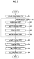
Fig. 2 is a flow chart showing a procedure of the production method according to the first embodiment of the present invention. -
Fig. 3 is a sectional view showing the enlarged member for fluid machines produced by the production method according to the first embodiment of the present invention, (a) shows a state before a smoothing step is performed, and (b) shows a state after the smoothing step is performed. -
Fig. 4 is a sectional view showing a member for fluid machines produced by a production method according to a second embodiment of the present invention. -
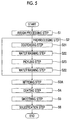
Fig. 5 is a flow chart showing a procedure of the production method according to the second embodiment of the present invention. - Hereinafter, a method for producing a member 1 for fluid machines (hereinafter, simply referred to as a member 1) according to a first embodiment of the present invention will be described.
- First, the member 1 which is produced by the production method of the present embodiment will be described. The member 1 is used in a steam turbine, a compressor, a pump, or the like, and a work fluid W such as gas or liquid comes into contact with the surface of the member 1 in the devices.
- As shown in
Fig. 1 , the member 1 includes abase 2 which is formed of a metal material such as a steel material (for example, stainless steel or carbon steel), anickel plating layer 3 which is laminated on thebase 2, and aglass coating layer 4 which is laminated on thenickel plating layer 3. - In the
base 2, a maximum height Ry in surface roughness of a surface side of thebase 2 to which thenickel plating layer 3 is laminated is 20 µm to 50 µm. - For example, the
nickel plating layer 3 is a Ni-B plating layer or a Ni-P plating layer. - The
glass coating layer 4 is a layer which is formed of a glass-based material. For example, the glass-based material may be a general glass material such as a glass material which is used in enamel processing. Specifically, in theglass coating layer 4, a glass frit composed of mainly SiO2 (silicon dioxide) and B2O3 (boron oxide), a reinforcement material such as Al2O3, an alkali material (solvent: Li2O (lithium oxide), Na2O (sodium oxide), K2O (potassium oxide), MgO (magnesium oxide), CaO (calcium oxide), BaO (barium oxide), or the like) for decreasing a melting point, a color former (this is nonessential), and water are mixed. - Next, with reference to
Fig. 2 , a procedure of the production method for producing the member 1 will be described. - The production method of the member 1 includes a rough processing step S1 which performs rough processing on the surface of the
base 2, a preprocessing step S2 which has a degreasing step S21, a water washing step S22, and a pickling step S23 which performs preprocessing on the surface of thebase 2 subjected to the rough processing, and a nickel plating step S3 which performs nickel plating processing on the surface of thebase 2 after the preprocessing. - In addition, the production method of the member 1 includes a coating step S4 which applies a glass-based material to the surface of the
base 2 after the nickel plating processing, a smoothing step S5 which removes some of the applied glass-based material, and a solidification step S6 which solidifies the applied glass-based material. - First, the rough processing step S1 is performed. That is, cutting is performed on the surface of the
base 2 using an end mill or the like so as to decrease the surface roughness of the surface of thebase 2. The maximum height Ry of the surface roughness on the surface of thebase 2 is 20 µm to 50 µm by performing the rough processing step S1. - Next, as the preprocessing step S2 with respect to the surface of the
base 2 after the rough processing, the degreasing step S21 which removes oil content is performed. Thereafter, the water washing step S22 which washes the base using water, the pickling step S23 which washes the base using an acid liquid such as hydrochloric acid or sulfuric acid so as to activate the surface of thebase 2, and the water washing step S22 are performed in this order. - Thereafter, the nickel plating step S3 is performed. That is, the
nickel plating layer 3 is formed on the surface of thebase 2 subjected to the preprocessing as described above. In the nickel plating step S3, electroplating, electroless nickel plating, or the like is applied. - The electroless nickel plating is a method which forms a nickel plating film on the surface of a member to be plated without supplying power to the member by dipping the surface of the member to be plated in a plating liquid. According to the electroless nickel plating, it is possible to uniformly form the film on a portion having a complicated shape such as an inner surface of a channel of an impeller.
- As the electroless nickel plating, Ni-B plating, NiP plating, or the like is exemplified. From the viewpoint of heat resistance with respect to the temperature of the glass-based material in the smoothing step S5 described below, preferably, the Ni-B plating is applied.
- Next, the coating step S4 is performed. The glass-based material is applied to the surface of the
base 2 on which thenickel plating layer 3 is formed. As the glass-based material, the above-described general glass material in a state of aqueous slurry or a molten glass is used. Viscosity of the aqueous slurry is 10-2 to 1 [Pa·s], and viscosity of the molten glass is 1 to 102 [Pa·s]. - In addition, as a method for applying the glass-based material, a dip coating method is used, in which after the
base 2 is dipped in a container in which the aqueous slurry or the molten glass is stored, thebase 2 is lifted. - Alternatively, as the method for applying the glass-based material, a dip coating method is used, in which water is removed from the aqueous slurry or the molten glass, the aqueous slurry or the molten glass in a powdery state is heated and melted in a container, the
base 2 is dipped in the container in a state where the aqueous slurry or the molten glass is heated up to the same temperature as the temperature of the glass-based material in the container, and thereafter, thebase 2 is lifted. - Alternatively, as the method for applying the glass-based material, a spray coating method is used in which the aqueous slurry is sprayed onto the surface of the
base 2 using a sprayer. - Thereafter, the smoothing step S5 is performed. That is, some of the glass-based material is removed while the glass-based material is heated. Specifically, in a state where the temperature of the glass-based material is maintained at 750°C to 850°C, spin coating in which the
base 2 having the applied glass-based material is rotated is performed, and some of the glass-based material is removed by centrifugal force so as to form a glass-based material layer having a smooth surface. Preferably, a rotation speed when thebase 2 is rotated by the spin coating is greater than a rotation speed at which uniformity of the film thickness of the glass-based material layer is maintained to some extent and smaller than a rotation speed at which the film thickness is too thin. Specifically, the spin coating is performed at a number of rotations of 60 rpm to 300 rpm, and more preferably, is performed at a number of rotations of 100 rpm to 200 rpm. - In addition, the solidification step S6 is performed. That is, the melted glass-based material is solidified so as to form the
glass coating layer 4 on the surface of thebase 2. Preferably, the thickness of theglass coating layer 4 is greater than a thickness at which theglass coating layer 4 is not influenced by the surface roughness of the surface of thebase 2 after the rough processing step S1 is performed and is smaller than a thickness at which adhesion of theglass coating layer 4 can be secured. Specifically, preferably, thickness of the glass coating is 0.05 mm to 1 mm, and more preferably, is 0.1 mm to 0.5 mm. - Moreover, after the
glass coating layer 4 is formed, preferably, the surface roughness of the surface of theglass coating layer 4 is greater than surface roughness at which there are too many required man hours in the smoothing step S5 and is smaller than surface roughness at which the contact resistance between theglass coating layer 4 and the fluid W is too great. Specifically, preferably, the surface roughness Ra is 0.01 µm to 0.1 µm, and more preferably, is 0.03 µm to 0.05 µm. - According to the method for producing the member 1, after the glass-based material is applied to the
base 2 in the coating step S4, some of the glass-based material is removed in the smoothing step S5. That is, the glass-based material is blown off while flowing as shown by arrows from a state ofFig. 3(a) and is brought into a state ofFig. 3(b) , and the surface of theglass coating layer 4 positioned on the side opposite to the surface of thebase 2 is smoothened. - Accordingly, even when the surface roughness of the surface of the
base 2 is increased, in a state where a step of decreasing the surface roughness of the surface of thebase 2 by polishing or the like before the coating step S4 is performed is not necessary, it is possible to achieve smoothing of the surface of the member 1. As a result, it is possible to decrease the contact resistance between the fluid W and the member 1, and it is possible to decrease an amount of matter attached to the member 1. - Since the method for producing the member 1 includes the rough processing step S1 before the coating step S4, the surface roughness of the surface of the
base 2 is decreased to some extent, and in a state where the maximum height Ry of the surface roughness is decreased, the coating step S4 is performed. - Here, the position of the maximum height Ry of the surface of the
base 2 becomes the minimum thickness dimension of the applied glass-based material. Accordingly, since the glass-based material is applied in the state where the surface roughness is decreased, it is possible to decrease the thickness dimension of the glass-based material. Therefore, it is possible to decrease time required for the coating step S4 and material costs of the glass-based material, and thus the costs are decreased. - Moreover, since the method for producing the member 1 includes the nickel plating step S3 in which the nickel plating processing is performed on the surface of the
base 2 after the rough processing step S1 and before the coating step S4, it is possible to form thenickel plating layer 3 on the surface of thebase 2. Accordingly, before the coating step S4 is performed, it is possible to prevent oxidation of the surface of thebase 2, and it is possible to improve adhesion between the glass-based material applied in the coating step S4 and thebase 2. - Moreover, since some of the glass-based material is removed using the spin coating in the smoothing step S5, it is possible to scatter the melted glass-based material by centrifugal force to remove the melted glass-based material, and it is possible to easily obtain the
glass coating layer 4 having a smooth surface. - According to the method for producing the member 1 of the present embodiment, since the glass-based material is applied to the
base 2 so as to smoothen the surface of thebase 2, polishing with respect to the surface of thebase 2 before the coating step S4 can be omitted, and it is possible to improve operating efficiency of a fluid machine having the member 1 while decreasing the cost of thebase 2. - Although it is not shown, the method for producing the member 1 may further include a post-processing step between the nickel plating step S3 and the coating step S4. The post-processing step includes a neutralization processing step in which after the
nickel plating layer 3 is formed on the surface of thebase 2, washing is performed on the surface of thenickel plating layer 3 by an alkaline aqueous solution ofpH 4 to pH 4.5. In addition, the post-processing step includes a water washing step of washing the surface of thenickel plating layer 3 after the neutralization processing, and a drying step of drying the surface. - Next, with reference to
Figs. 4 and5 , a method of producing amember 1A according to a second embodiment of the present invention will be described. - The method for producing the
member 1A of the present embodiment includes a nitriding step S3A instead of the nickel plating step S3 of the first embodiment. - That is, the method for producing the
member 1A includes the rough processing step S1, the preprocessing step S2, the nitriding step S3A of performing nitriding processing on the surface of thebase 2 after the preprocessing so as to harden the surface of thebase 2, the coating step S4 after the nitriding step S3A, the smoothing step S5, and the solidification step S6. - For example, in the nitriding step S3A, nitriding processing such as gas nitriding, ion nitriding, or radical nitriding is performed on the surface of the
base 2 after the preprocessing step S2, and anitride layer 3A between theglass coating layer 4 and the surface of thebase 2. Thenitride layer 3A is a layer formed of dense nitride. - Here, the gas nitriding is a nitriding method in which nitrogen is diffused to a surface of a material to be processed by a reaction in which ammonia gas is dissolved into nitrogen and hydrogen and a nitride (or solid solution) layer is formed.
- The ion nitriding is a nitriding method in which nitrogen and hydrogen are introduced into a furnace as reaction gas, plasma is generated on the surface of the material to be processed, ionized nitrogen is diffused to the surface of the material to be processed, and a nitride (solid solution) layer is formed.
- The radical nitriding is a nitriding method in which a mixed gas of hydrogen and ammonia is introduced into the furnace as reaction gas, plasma is generated on the surface of the material to be processed, radical nitrogen is diffused to the surface of the material to be processed, and a nitride (or solid solution) layer is formed.
- In the nitriding step S3A, any one of the above-described nitriding methods may be used. However, since a compound layer is not formed when the nitriding processing is performed, the radical nitriding is more suitable.
- The compound layer is a layer which exists on the outermost surface of the nitride material to be processed and has a thickness of 10 µm or less and is a layer of composite nitride such as steel and chromium. Since the compound layer is brittle and is easily cracked, the surface is easily roughened, and when the compound layer is not formed, it is possible to obtain high adhesion between the
glass coating layer 4 and thenitride layer 3A. - According to the method for producing the
member 1A of the present embodiment, similar to the first embodiment, the polishing with respect to the surface of thebase 2 before the coating step S4 can be omitted, and it is possible to improve operating efficiency of the fluid machine having themember 1A while decreasing the cost of thebase 2. - In addition, in the method of the present embodiment, by performing the nitriding step S3A, a
dense nitride layer 3A is formed on the surface of thebase 2. Accordingly, it is possible to improve adhesion between the glass-based material applied in the coating step S4 and thebase 2. - Hereinbefore, embodiments of the present invention are described in detail. However, some design modifications may be performed within a scope which does not depart from the technical idea of the present invention.
- For example, the rough processing step S1 may not necessarily be performed.
- In addition, in the preprocessing S2, the degreasing step S21, the pickling step S23, and the water washing step S22 may be appropriately repeated according to the conditions of the surface of the
base 2, and some steps may be omitted. - Moreover, in the smoothing step S5, instead of the spin coating, a method may be used in which some of the glass-based material is blown off by pressure of air so as to remove some of the glass-based material, and a method may be used in which vibration is applied to the
base 2 so as to remove some of the glass-based material. - According to the method for producing a member for fluid machines and the member for fluid machines, a glass-based material is applied to a base so as to smoothen the surface of the base, and it possible to improve operating efficiency of the fluid machine while decreasing costs of the base.
-
- 1, 1A:
- member (for fluid machine)
- 2:
- base
- 3:
- nickel plating layer
- 3A:
- nitride layer
- 4:
- glass coating layer
- S1:
- rough processing step
- S2:
- preprocessing step
- S21:
- degreasing step
- S22:
- water washing step
- S23:
- pickling step
- S3:
- nickel plating step
- S3A:
- nitriding step
- S4:
- coating step
- S5:
- smoothing step
- S6:
- solidification step
- W:
- fluid
Claims (8)
- A method for producing a member of fluid machines, comprising:a coating step of applying a glass-based material to a surface of a base;a smoothing step of removing some of the glass-based material while heating and melting the glass-based material after the coating step; anda solidification step of solidifying the heated and melted glass-based material after the smoothing step.
- The method for producing a member of fluid machines according to claim 1, further comprising:a rough processing step of performing rough processing on the surface of the base before the coating step.
- The method for producing a member of fluid machines according to claim 1 or 2, further comprising:a nickel plating step of performing nickel plating processing on the surface of the base before the coating step.
- The method for producing a member of fluid machines according to claim 1 or 2, further comprising:a nitriding step of performing nitriding processing on the surface of the base so as to harden the surface before the coating step.
- The method for producing a member of fluid machines according to any one of claims 1 to 4,
wherein in the smoothing step, the base is rotated and some of the glass-based material is removed. - A member for fluid machines, comprising:a base in which a fluid flows to a surface side of the base; anda glass coating layer which is applied to the surface of the base and in which a surface positioned on a side opposite to the surface of the base formed of a glass-based material is smooth.
- The member for fluid machines according to claim 6, further comprising:a nickel plating layer which is provided between the base and the glass coating layer.
- The member for fluid machines according to claim 6, further comprising:a nitride layer which is provided between the base and the glass coating layer.
Applications Claiming Priority (2)
| Application Number | Priority Date | Filing Date | Title |
|---|---|---|---|
| JP2013204623A JP6300398B2 (en) | 2013-09-30 | 2013-09-30 | Method for manufacturing fluid machine member |
| PCT/JP2014/069446 WO2015045595A1 (en) | 2013-09-30 | 2014-07-23 | Method for producing member for fluid machines, and member for fluid machines |
Publications (2)
| Publication Number | Publication Date |
|---|---|
| EP3054109A1 true EP3054109A1 (en) | 2016-08-10 |
| EP3054109A4 EP3054109A4 (en) | 2017-05-31 |
Family
ID=52742752
Family Applications (1)
| Application Number | Title | Priority Date | Filing Date |
|---|---|---|---|
| EP14846780.6A Withdrawn EP3054109A4 (en) | 2013-09-30 | 2014-07-23 | Method for producing member for fluid machines, and member for fluid machines |
Country Status (5)
| Country | Link |
|---|---|
| US (1) | US20160186767A1 (en) |
| EP (1) | EP3054109A4 (en) |
| JP (1) | JP6300398B2 (en) |
| CN (1) | CN105408588B (en) |
| WO (1) | WO2015045595A1 (en) |
Families Citing this family (5)
| Publication number | Priority date | Publication date | Assignee | Title |
|---|---|---|---|---|
| JP7075781B2 (en) * | 2017-02-28 | 2022-05-26 | 株式会社放電精密加工研究所 | Highly smooth coating composition that can realize a low surface roughness coating film, this construction method and repair method, and a compressor that has been surface-treated using these. |
| US10598046B2 (en) | 2018-07-11 | 2020-03-24 | United Technologies Corporation | Support straps and method of assembly for gas turbine engine |
| CN110592578A (en) * | 2019-09-05 | 2019-12-20 | 华庚新材料科技(嘉兴)有限公司 | Composite material |
| CN110699685A (en) * | 2019-09-05 | 2020-01-17 | 华庚新材料科技(嘉兴)有限公司 | Method for producing composite material |
| JP7717000B2 (en) * | 2022-02-01 | 2025-08-01 | 三菱重工コンプレッサ株式会社 | Compressor System |
Family Cites Families (23)
| Publication number | Priority date | Publication date | Assignee | Title |
|---|---|---|---|---|
| GB269262A (en) * | 1926-01-19 | 1927-04-19 | Wesley Lambert | Improvements in and connected with the lining of metal pipes |
| PL96083B1 (en) * | 1975-01-18 | 1977-12-31 | METHOD OF FIRE-SUBMERSIBLE ALUMINATION OF IRON-ALLOY PRODUCTS | |
| JPH03136846A (en) * | 1989-10-23 | 1991-06-11 | Toshiba Corp | Preparation of heat-resistant and abrasion-resistant member |
| US5992980A (en) * | 1991-08-02 | 1999-11-30 | Canon Kabushiki Kaisha | Substrate for ink jet head, ink jet head provided with said substrate and ink jet apparatus having such ink jet head |
| JP3188524B2 (en) * | 1991-08-02 | 2001-07-16 | キヤノン株式会社 | Substrate for inkjet head, inkjet head using the substrate, and inkjet apparatus equipped with the head |
| JPH0531903A (en) * | 1991-08-02 | 1993-02-09 | Canon Inc | Ink jet head substrate, ink jet head using the same, and ink jet apparatus equipped with the ink jet head |
| JPH05160018A (en) * | 1991-12-04 | 1993-06-25 | Fujitsu Ltd | Spin coating method |
| FR2685693B1 (en) * | 1991-12-30 | 1994-06-03 | Europ Propulsion | PROCESS FOR PRODUCING PROTECTION AGAINST OXIDATION OF COMPOSITE MATERIAL PRODUCTS, AND PRODUCTS THUS PROTECTED. |
| JP3269001B2 (en) * | 1997-04-11 | 2002-03-25 | 株式会社ノリタケカンパニーリミテド | Method for producing high radiation glass coating material and method for producing high radiation glass film |
| JP3457199B2 (en) * | 1999-01-12 | 2003-10-14 | 松下電器産業株式会社 | Method for manufacturing plasma display panel |
| JP4143306B2 (en) * | 2002-01-30 | 2008-09-03 | Jfeスチール株式会社 | Method for producing coated steel sheet |
| FR2850649B1 (en) * | 2003-01-30 | 2005-04-29 | Snecma Propulsion Solide | PROCESS FOR THE SURFACE TREATMENT OF A THERMOSTRUCTURAL COMPOSITE MATERIAL PART AND APPLICATION TO THE BRAZING OF THERMOSTRUCTURAL COMPOSITE MATERIAL PARTS |
| JP2005077945A (en) * | 2003-09-02 | 2005-03-24 | Toshiba Matsushita Display Technology Co Ltd | Method for manufacturing display device |
| US20050053800A1 (en) * | 2003-09-04 | 2005-03-10 | General Electric Company | Method for post deposition of beta phase nickel aluminide coatings |
| US20070104886A1 (en) * | 2005-11-10 | 2007-05-10 | General Electric Company | Electrostatic spray for coating aircraft engine components |
| JP3757418B1 (en) * | 2005-01-19 | 2006-03-22 | 石川島播磨重工業株式会社 | Method for local application of diffusion aluminide coating |
| JP4918253B2 (en) | 2005-12-15 | 2012-04-18 | 三菱重工業株式会社 | Rotating machine with surface smoothing film |
| US20090098286A1 (en) * | 2007-06-11 | 2009-04-16 | Honeywell International, Inc. | Method for forming bond coats for thermal barrier coatings on turbine engine components |
| JP5274809B2 (en) * | 2007-10-05 | 2013-08-28 | 花王株式会社 | Manufacturing method of low dielectric constant film |
| FR2944010B1 (en) * | 2009-04-02 | 2012-07-06 | Snecma Propulsion Solide | METHOD FOR SMOOTHING THE SURFACE OF A PIECE OF CMC MATERIAL |
| US20110027467A1 (en) * | 2009-07-31 | 2011-02-03 | Glen Harold Kirby | Methods of making environmental barrier coatings for high temperature ceramic components using sintering aids |
| JP2011241800A (en) * | 2010-05-21 | 2011-12-01 | Ihi Corp | Coating having corrosion resistance at high temperature |
| FR2979629B1 (en) * | 2011-09-06 | 2013-09-27 | Snecma Propulsion Solide | METHOD OF FORMING ON A CMC SUBSTRATE CONTAINING SIC OF A SMOOTH COATING OF ICE ASPECT AND CMC PART PROVIDED WITH SUCH COATING |
-
2013
- 2013-09-30 JP JP2013204623A patent/JP6300398B2/en not_active Expired - Fee Related
-
2014
- 2014-07-23 CN CN201480042226.6A patent/CN105408588B/en not_active Expired - Fee Related
- 2014-07-23 EP EP14846780.6A patent/EP3054109A4/en not_active Withdrawn
- 2014-07-23 US US14/907,731 patent/US20160186767A1/en not_active Abandoned
- 2014-07-23 WO PCT/JP2014/069446 patent/WO2015045595A1/en not_active Ceased
Also Published As
| Publication number | Publication date |
|---|---|
| EP3054109A4 (en) | 2017-05-31 |
| US20160186767A1 (en) | 2016-06-30 |
| JP2015066523A (en) | 2015-04-13 |
| WO2015045595A1 (en) | 2015-04-02 |
| CN105408588B (en) | 2017-05-17 |
| CN105408588A (en) | 2016-03-16 |
| JP6300398B2 (en) | 2018-03-28 |
Similar Documents
| Publication | Publication Date | Title |
|---|---|---|
| US20160186767A1 (en) | Method for producing member for fluid machines, and member for fluid machines | |
| JP6581978B2 (en) | High purity metal top coat for semiconductor manufacturing components | |
| CN104805485A (en) | Die-cast aluminum alloy surface treatment method | |
| CN106148876B (en) | A kind of novel aluminum alloy die-casting die surface peening coating and preparation method thereof | |
| CN103240391B (en) | Method for preparing metal core for investment casting and precision investment casting method for aluminum alloy casting based on metal core | |
| JP2002526276A (en) | Inner surface treatment method for hollow structural parts | |
| CN106282881A (en) | Phosphatization or anodic oxidation are to improve the bonding of thermal spraying figure layer in electromotor cylinder bore | |
| CN107937912A (en) | Automobile die method for treating surface layer | |
| JP2005272923A (en) | Product comprising magnesium or magnesium alloy and method for producing the same | |
| CN102345126B (en) | Method for treating surface of metal workpiece | |
| CN101760714B (en) | Method for immersion-plating titanium alloy parts | |
| EP3080323B1 (en) | Electroformed nickel-chromium alloy | |
| CN101970165A (en) | Method for producing a component for a heat engine | |
| CN104593620B (en) | The aluminum liquid degasification rotor preparation of a kind of corrosion of resistance to aluminum abrasion and restorative procedure thereof | |
| EP2104591B1 (en) | Process for surface preparation of parts to be coated | |
| CN104874752B (en) | The spraying method of metal-type casting coating | |
| JP4350212B2 (en) | Manufacturing method of high corrosion resistance casting of magnesium alloy and high corrosion resistance casting | |
| CN106984772B (en) | A kind of casting method of high-precision drill bit | |
| CN103343313B (en) | Method for improving abrasive resistance of overhang hardware fittings of power transmission line | |
| CN114645306B (en) | Method for preparing large-size cBN particles nickel-based coating on the surface of complex-shaped workpieces | |
| CN110804751B (en) | Pretreatment method for preparing metal coating on the surface of cast metal parts, metal coating parts of cast metal parts and preparation method thereof | |
| TW201404944A (en) | Manufacturing method for metal oxidizing layer | |
| CN103158292A (en) | Wear resistant blade and processing method thereof | |
| JP2008190656A (en) | Bearing device and manufacturing method thereof | |
| CN106637169A (en) | Novel carbon steel water-supply equipment pretreatment process |
Legal Events
| Date | Code | Title | Description |
|---|---|---|---|
| PUAI | Public reference made under article 153(3) epc to a published international application that has entered the european phase |
Free format text: ORIGINAL CODE: 0009012 |
|
| 17P | Request for examination filed |
Effective date: 20160127 |
|
| AK | Designated contracting states |
Kind code of ref document: A1 Designated state(s): AL AT BE BG CH CY CZ DE DK EE ES FI FR GB GR HR HU IE IS IT LI LT LU LV MC MK MT NL NO PL PT RO RS SE SI SK SM TR |
|
| AX | Request for extension of the european patent |
Extension state: BA ME |
|
| DAX | Request for extension of the european patent (deleted) | ||
| A4 | Supplementary search report drawn up and despatched |
Effective date: 20170502 |
|
| RIC1 | Information provided on ipc code assigned before grant |
Ipc: C23C 28/00 20060101ALI20170424BHEP Ipc: C23D 5/04 20060101AFI20170424BHEP Ipc: F04D 29/30 20060101ALI20170424BHEP Ipc: F01D 25/00 20060101ALI20170424BHEP Ipc: C23D 5/02 20060101ALI20170424BHEP Ipc: C23C 24/08 20060101ALI20170424BHEP Ipc: B05D 7/24 20060101ALI20170424BHEP |
|
| RIC1 | Information provided on ipc code assigned before grant |
Ipc: C23C 28/00 20060101ALI20171211BHEP Ipc: C23C 8/26 20060101ALI20171211BHEP Ipc: C23C 28/04 20060101ALI20171211BHEP Ipc: C23D 5/00 20060101ALI20171211BHEP Ipc: F01D 5/28 20060101ALI20171211BHEP Ipc: F04D 29/26 20060101ALI20171211BHEP Ipc: C23D 5/04 20060101ALI20171211BHEP Ipc: F04D 29/18 20060101ALI20171211BHEP Ipc: C23C 18/18 20060101ALN20171211BHEP Ipc: C23C 8/38 20060101ALI20171211BHEP Ipc: C23C 18/32 20060101ALI20171211BHEP Ipc: F04D 29/24 20060101ALI20171211BHEP Ipc: C23C 8/02 20060101AFI20171211BHEP Ipc: F04D 29/30 20060101ALI20171211BHEP Ipc: F04D 29/02 20060101ALI20171211BHEP Ipc: C23D 5/02 20060101ALI20171211BHEP |
|
| GRAP | Despatch of communication of intention to grant a patent |
Free format text: ORIGINAL CODE: EPIDOSNIGR1 |
|
| INTG | Intention to grant announced |
Effective date: 20180131 |
|
| INTG | Intention to grant announced |
Effective date: 20180207 |
|
| STAA | Information on the status of an ep patent application or granted ep patent |
Free format text: STATUS: THE APPLICATION IS DEEMED TO BE WITHDRAWN |
|
| 18D | Application deemed to be withdrawn |
Effective date: 20180619 |