EP3054107B1 - Ensemble turbine possédant un verrouillage de système de rotor - Google Patents
Ensemble turbine possédant un verrouillage de système de rotor Download PDFInfo
- Publication number
- EP3054107B1 EP3054107B1 EP16154368.1A EP16154368A EP3054107B1 EP 3054107 B1 EP3054107 B1 EP 3054107B1 EP 16154368 A EP16154368 A EP 16154368A EP 3054107 B1 EP3054107 B1 EP 3054107B1
- Authority
- EP
- European Patent Office
- Prior art keywords
- case
- rotor
- fuse
- turbine assembly
- assembly
- Prior art date
- Legal status (The legal status is an assumption and is not a legal conclusion. Google has not performed a legal analysis and makes no representation as to the accuracy of the status listed.)
- Active
Links
- 239000004753 textile Substances 0.000 claims description 10
- 238000000034 method Methods 0.000 claims description 6
- 239000000463 material Substances 0.000 claims description 5
- 229920000049 Carbon (fiber) Polymers 0.000 claims description 4
- ATJFFYVFTNAWJD-UHFFFAOYSA-N Tin Chemical compound [Sn] ATJFFYVFTNAWJD-UHFFFAOYSA-N 0.000 claims description 4
- 239000000956 alloy Substances 0.000 claims description 4
- 229910045601 alloy Inorganic materials 0.000 claims description 4
- 239000004917 carbon fiber Substances 0.000 claims description 4
- 238000004519 manufacturing process Methods 0.000 claims description 4
- VNWKTOKETHGBQD-UHFFFAOYSA-N methane Chemical compound C VNWKTOKETHGBQD-UHFFFAOYSA-N 0.000 claims description 4
- 239000003990 capacitor Substances 0.000 claims description 3
- 230000008878 coupling Effects 0.000 claims description 3
- 238000010168 coupling process Methods 0.000 claims description 3
- 238000005859 coupling reaction Methods 0.000 claims description 3
- 230000000712 assembly Effects 0.000 description 5
- 238000000429 assembly Methods 0.000 description 5
- 238000002485 combustion reaction Methods 0.000 description 4
- 230000003068 static effect Effects 0.000 description 3
- 230000001419 dependent effect Effects 0.000 description 2
- 239000000446 fuel Substances 0.000 description 2
- 238000004804 winding Methods 0.000 description 2
- 238000010586 diagram Methods 0.000 description 1
- 230000005496 eutectics Effects 0.000 description 1
- 239000000284 extract Substances 0.000 description 1
- 239000000155 melt Substances 0.000 description 1
- 230000001737 promoting effect Effects 0.000 description 1
Images


Classifications
-
- F—MECHANICAL ENGINEERING; LIGHTING; HEATING; WEAPONS; BLASTING
- F01—MACHINES OR ENGINES IN GENERAL; ENGINE PLANTS IN GENERAL; STEAM ENGINES
- F01D—NON-POSITIVE DISPLACEMENT MACHINES OR ENGINES, e.g. STEAM TURBINES
- F01D19/00—Starting of machines or engines; Regulating, controlling, or safety means in connection therewith
-
- F—MECHANICAL ENGINEERING; LIGHTING; HEATING; WEAPONS; BLASTING
- F01—MACHINES OR ENGINES IN GENERAL; ENGINE PLANTS IN GENERAL; STEAM ENGINES
- F01D—NON-POSITIVE DISPLACEMENT MACHINES OR ENGINES, e.g. STEAM TURBINES
- F01D21/00—Shutting-down of machines or engines, e.g. in emergency; Regulating, controlling, or safety means not otherwise provided for
-
- B—PERFORMING OPERATIONS; TRANSPORTING
- B64—AIRCRAFT; AVIATION; COSMONAUTICS
- B64D—EQUIPMENT FOR FITTING IN OR TO AIRCRAFT; FLIGHT SUITS; PARACHUTES; ARRANGEMENT OR MOUNTING OF POWER PLANTS OR PROPULSION TRANSMISSIONS IN AIRCRAFT
- B64D7/00—Arrangements of military equipment, e.g. armaments, armament accessories, or military shielding, in aircraft; Adaptations of armament mountings for aircraft
-
- F—MECHANICAL ENGINEERING; LIGHTING; HEATING; WEAPONS; BLASTING
- F01—MACHINES OR ENGINES IN GENERAL; ENGINE PLANTS IN GENERAL; STEAM ENGINES
- F01D—NON-POSITIVE DISPLACEMENT MACHINES OR ENGINES, e.g. STEAM TURBINES
- F01D25/00—Component parts, details, or accessories, not provided for in, or of interest apart from, other groups
- F01D25/24—Casings; Casing parts, e.g. diaphragms, casing fastenings
-
- F—MECHANICAL ENGINEERING; LIGHTING; HEATING; WEAPONS; BLASTING
- F01—MACHINES OR ENGINES IN GENERAL; ENGINE PLANTS IN GENERAL; STEAM ENGINES
- F01D—NON-POSITIVE DISPLACEMENT MACHINES OR ENGINES, e.g. STEAM TURBINES
- F01D5/00—Blades; Blade-carrying members; Heating, heat-insulating, cooling or antivibration means on the blades or the members
- F01D5/02—Blade-carrying members, e.g. rotors
-
- F—MECHANICAL ENGINEERING; LIGHTING; HEATING; WEAPONS; BLASTING
- F01—MACHINES OR ENGINES IN GENERAL; ENGINE PLANTS IN GENERAL; STEAM ENGINES
- F01D—NON-POSITIVE DISPLACEMENT MACHINES OR ENGINES, e.g. STEAM TURBINES
- F01D5/00—Blades; Blade-carrying members; Heating, heat-insulating, cooling or antivibration means on the blades or the members
- F01D5/12—Blades
-
- F—MECHANICAL ENGINEERING; LIGHTING; HEATING; WEAPONS; BLASTING
- F01—MACHINES OR ENGINES IN GENERAL; ENGINE PLANTS IN GENERAL; STEAM ENGINES
- F01D—NON-POSITIVE DISPLACEMENT MACHINES OR ENGINES, e.g. STEAM TURBINES
- F01D9/00—Stators
- F01D9/02—Nozzles; Nozzle boxes; Stator blades; Guide conduits, e.g. individual nozzles
- F01D9/04—Nozzles; Nozzle boxes; Stator blades; Guide conduits, e.g. individual nozzles forming ring or sector
- F01D9/041—Nozzles; Nozzle boxes; Stator blades; Guide conduits, e.g. individual nozzles forming ring or sector using blades
-
- F—MECHANICAL ENGINEERING; LIGHTING; HEATING; WEAPONS; BLASTING
- F02—COMBUSTION ENGINES; HOT-GAS OR COMBUSTION-PRODUCT ENGINE PLANTS
- F02C—GAS-TURBINE PLANTS; AIR INTAKES FOR JET-PROPULSION PLANTS; CONTROLLING FUEL SUPPLY IN AIR-BREATHING JET-PROPULSION PLANTS
- F02C7/00—Features, components parts, details or accessories, not provided for in, or of interest apart form groups F02C1/00 - F02C6/00; Air intakes for jet-propulsion plants
- F02C7/26—Starting; Ignition
-
- F—MECHANICAL ENGINEERING; LIGHTING; HEATING; WEAPONS; BLASTING
- F42—AMMUNITION; BLASTING
- F42B—EXPLOSIVE CHARGES, e.g. FOR BLASTING, FIREWORKS, AMMUNITION
- F42B15/00—Self-propelled projectiles or missiles, e.g. rockets; Guided missiles
-
- F—MECHANICAL ENGINEERING; LIGHTING; HEATING; WEAPONS; BLASTING
- F05—INDEXING SCHEMES RELATING TO ENGINES OR PUMPS IN VARIOUS SUBCLASSES OF CLASSES F01-F04
- F05D—INDEXING SCHEME FOR ASPECTS RELATING TO NON-POSITIVE-DISPLACEMENT MACHINES OR ENGINES, GAS-TURBINES OR JET-PROPULSION PLANTS
- F05D2220/00—Application
- F05D2220/30—Application in turbines
- F05D2220/32—Application in turbines in gas turbines
-
- F—MECHANICAL ENGINEERING; LIGHTING; HEATING; WEAPONS; BLASTING
- F05—INDEXING SCHEMES RELATING TO ENGINES OR PUMPS IN VARIOUS SUBCLASSES OF CLASSES F01-F04
- F05D—INDEXING SCHEME FOR ASPECTS RELATING TO NON-POSITIVE-DISPLACEMENT MACHINES OR ENGINES, GAS-TURBINES OR JET-PROPULSION PLANTS
- F05D2230/00—Manufacture
- F05D2230/60—Assembly methods
-
- F—MECHANICAL ENGINEERING; LIGHTING; HEATING; WEAPONS; BLASTING
- F05—INDEXING SCHEMES RELATING TO ENGINES OR PUMPS IN VARIOUS SUBCLASSES OF CLASSES F01-F04
- F05D—INDEXING SCHEME FOR ASPECTS RELATING TO NON-POSITIVE-DISPLACEMENT MACHINES OR ENGINES, GAS-TURBINES OR JET-PROPULSION PLANTS
- F05D2260/00—Function
- F05D2260/30—Retaining components in desired mutual position
- F05D2260/31—Retaining bolts or nuts
- F05D2260/311—Retaining bolts or nuts of the frangible or shear type
-
- F—MECHANICAL ENGINEERING; LIGHTING; HEATING; WEAPONS; BLASTING
- F05—INDEXING SCHEMES RELATING TO ENGINES OR PUMPS IN VARIOUS SUBCLASSES OF CLASSES F01-F04
- F05D—INDEXING SCHEME FOR ASPECTS RELATING TO NON-POSITIVE-DISPLACEMENT MACHINES OR ENGINES, GAS-TURBINES OR JET-PROPULSION PLANTS
- F05D2260/00—Function
- F05D2260/85—Starting
-
- F—MECHANICAL ENGINEERING; LIGHTING; HEATING; WEAPONS; BLASTING
- F05—INDEXING SCHEMES RELATING TO ENGINES OR PUMPS IN VARIOUS SUBCLASSES OF CLASSES F01-F04
- F05D—INDEXING SCHEME FOR ASPECTS RELATING TO NON-POSITIVE-DISPLACEMENT MACHINES OR ENGINES, GAS-TURBINES OR JET-PROPULSION PLANTS
- F05D2260/00—Function
- F05D2260/99—Ignition, e.g. ignition by warming up of fuel or oxidizer in a resonant acoustic cavity
Definitions
- the present disclosure relates generally to gas turbine engines, and more specifically to turbine assemblies having a rotor system lock.
- Gas turbine engines typically include alternating stages of static vane assemblies and rotating wheel assemblies.
- the rotating wheel assemblies include disks carrying blades around their outer edges. These rotating wheel assemblies may be unintentionally turned (or windmilled) by the passage of air through the engine.
- Rotating components of a gas turbine engine can experience windmilling when wind flows through the engine while it is at rest due to high winds or during pre-launch flight due to ram air. This causes the rotor systems within the gas turbine engine to turn at undesired times and speeds which may damage components of the engine such as bearings, seals, and blades, among others.
- Document US5660357A discloses a missile engine inlet cover that has an elongate air scoop having a rigid forward shell and a rearward attached flexible molded end piece.
- a turbine assembly for use in a gas turbine engine includes a case, a rotor mounted in the case to rotate relative to the case, and a fuse.
- the fuse may be adapted to provide a rotor system lock that selectively blocks rotation of the rotor relative to the case.
- the case includes a support housing and a plurality of vanes coupled to the support housing.
- the rotor includes a wheel and a plurality of blades coupled to the wheel.
- the fuse extends from at least one vane included in the case to at least one blade included in the rotor to block rotation of the rotor relative to the case.
- the fuse disintegrates in response to the application of a predetermined current so that the rotor is allowed to rotate relative to the case.
- the fuse may include a first wrap that extends around at least one vane included in the case and at least one blade included in the rotor.
- the fuse may further include a second wrap spaced circumferentially from the first wrap that extends around at least one vane included in the case and at least one blade included in the rotor.
- the fuse may include a metallic wire, and the metallic wire may include a tin-based alloy. In some embodiments, the fuse may include a textile band, and the textile band may include carbon fiber. In some embodiments, the predetermined current for causing disintegration of the fuse may be less than 20 amps.
- a turbine assembly for use in a gas turbine engine includes a case, a rotor mounted in the case to rotate relative to the case, and a fuse.
- the fuse may be adapted to provide a rotor system lock that selectively blocks rotation of the rotor relative to the case.
- the case includes a support housing and a plurality of vanes coupled to the support housing.
- the rotor includes a wheel and a plurality of blades coupled to the wheel.
- the fuse extends from the case to the rotor to block rotation of the rotor relative to the case.
- the fuse disintegrates in response to the application of a predetermined current so that the rotor is allowed to rotate relative to the case.
- the turbine assembly includes an electrical power source coupled to the fuse to provide the predetermined current to the fuse.
- the electrical power source may be selected from one of a generator, a capacitor, and a battery.
- the fuse may include a first wrap that extends around at least one vane included in the case and at least one blade included in the rotor.
- the fuse may further include a second wrap spaced circumferentially from the first wrap that extends around at least one vane included in the case and at least one blade included in the rotor.
- the fuse may include a metallic wire that extends around a first vane and a first blade to provide the first wrap and a second metallic wire that extends around a second vane and a second blade to provide the second wrap.
- the first and the second metallic wire may include a tin-based alloy.
- the fuse may include a textile band that extends around a first vane and a first blade to provide the first wrap and a second metallic wire that extends around a second vane and a second blade to provide the second wrap.
- the first and the second textile band may include carbon fiber.
- the predetermined current may be less than 20 amps.
- an assembly for use in a gas turbine engine includes a case, a rotor mounted in the case to rotate relative to the case, and a fuse.
- the fuse may be adapted to provide a rotor system lock that selectively blocks rotation of the rotor relative to the case.
- the fuse extend from the case to the rotor to block rotation of the rotor relative to the case.
- the fuse disintegrates in response to the application of a predetermined current so that the rotor is allowed to rotate relative to the case.
- the fuse may include a first wrap that extends around a first component included in the case and a first component included in the rotor.
- the fuse may also include and a second wrap spaced circumferentially from the first wrap that extends around a second component included in the case and a second component included in the rotor.
- the fuse includes a metallic wire.
- the predetermined current for causing disintegration of the fuse may be less than 20 amps.
- a method of making a turbine assembly includes mounting a rotor in a case for rotation relative to the case and fashioning a fuse between at least on blade included in the rotor and at least one vane included in the case to block rotation of the rotor relative to the case.
- the fuse is made from a material that disintegrates in response to the application of a predetermined current so that the rotor is allowed to rotate relative to the case.
- the method further includes coupling an electrical power source to the fuse to provide the predetermined current to the fuse.
- the predetermined current may be less than 20 amps.
- An aircraft 10 may include fixed wings 11, 12 under which may be suspended secondary air vehicles such as missiles 14, 16 as shown, for example, in Fig. 1 .
- Other examples of secondary air vehicles include experimental aircraft, spacecraft, or any other air vehicle with rotating components that may be exposed to ram air during pre-launch flight.
- Each illustrative missile 14, 16 includes a payload 18 and a gas turbine engine 20. Air flows through the gas turbine engine 20 during ferrying of the missiles 14, 16 by the aircraft 10 as suggested by the arrows 21, 22 in Fig. 2 . The air flowing through the gas turbine engine 20 may induce unintended rotation (or windmilling) of components included in the gas turbine engine 20 and may damage the gas turbine engine 20.
- the illustrative gas turbine engine 20 of each missile 14, 16 includes a compressor assembly 24, a combustor assembly 26, and a turbine assembly 28 as shown in Fig. 3 .
- the compressor assembly 24 compresses and delivers air to the combustor assembly 26.
- the combustor assembly 26 mixes fuel with the compressed air received from the compressor assembly 24 and ignites the fuel.
- the hot high pressure products of the combustion reaction in the combustor assembly 26 are directed into the turbine assembly 28 and the turbine assembly 28 extracts work to drive the compressor assembly 24 and exhausts thrust to propel the engine 20 as suggested in Fig. 3 .
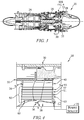
- the turbine assembly 28 illustratively includes a case 30 with a support housing 32, and a plurality of vanes 34 coupled to the support housing 32, as shown in Figs. 3 and 4 .
- a rotor 36 may be mounted in the case 30 to rotate relative to the case 30 and includes a wheel 38 and a plurality of blades 40.
- the vanes 34 of the case 30 may extend across the flow path of the hot, high-pressure combustion products from the combustor assembly 26 to direct the combustion products toward the blades 40 of the rotor 36.
- the blades 40 may in turn be pushed by the combustion products to cause the rotor 36 to rotate and thereby drive the rotating components of the compressor assembly 24.
- the illustrative turbine assembly 28 includes a fuse 50 that provides a rotor system lock adapted to block unintended rotation (or windmilling) of components in the gas turbine engine 20 as suggested in Fig. 4 .
- the illustrative fuse 50 extends from at least one of the plurality of vanes 34 included in the case 30 to at least one blade 40 included in the rotor 36, as shown in Fig. 4 .
- the fuse 50 may include a plurality of wraps 51, 52 spaced circumferentially from one another that each extend around one or more vanes 34 and one or more blades 40 in order to block rotation of the rotor 36 relative to the case when air flows over the blades when the engine is not in operation, for example, when the engine 20 is ferried in a missile 14, 16 by the aircraft 10.
- the number of wraps 51, 52 included in the fuse will be dependent on the operating conditions of the gas turbine engine 20, and should be sufficient to block rotation of the rotor 36 relative to the case 30 during periods when the gas turbine engine 20 is experiencing conditions that may cause unintentional rotation or windmilling.
- the fuse 50 may also reduce the potential for foreign object damage (FOD) to the gas turbine engine 20 before or after release of the illustrative missiles 14, 16 from the aircraft 10.
- the fuse 50 may extend from other rotating components in the engine 20 to other static components in the engine 20 to block unintended rotation.
- the fuse 50 may extend around or between compressor vanes and compressor blades; between sump housings and rotor shafts; or between any other suitable combination of static and dynamic structure within the engine 20.
- the fuse 50 may be shaped and/or manufactured in various forms other than into wraps 51, 52 to engage components of the engine 20.
- the fuse 50 may form one or more hooks, welds, buttons, or other connection features to engage components of the engine 20.
- each wrap 51, 52 includes a metallic wire 60 that forms a plurality of loops 61, 62, 63 as shown in Fig. 4 .
- the metallic wire 60 is made from a eutectic tin-based alloy adapted to melt in response to the application of an electrical current.
- the wire 60 may be made from other suitable materials.
- each wrap 51, 52 may include a textile band. The textile band may be made from a carbon-fiber material or another suitable material adapted to burn or break down in response to the application of an electrical current.
- the turbine assembly 20 also includes an electrical power source 70 as shown diagrammatically in Fig. 4 .
- the power source 70 is coupled to the fuse 50 and is configured to apply a predetermined current to the fuse 50.
- the fuse 50 disintegrates (melts, burns, or otherwise breaks down to a weakened or broken state) to free the blades 40 from the vanes 34 and allow the rotor 36 to move relative to the case 30.
- the electrical power source 70 may be a generator, a capacitor, or a battery adapted to apply 20 amps or less to the fuse 50.
- the power source 70 is configured to provide a predetermined electrical current to the fuse during engine start-up so that the gas turbine engine may operate normally upon release of a missile 14, 16 from the aircraft 10, or in response to a use input.
- the predetermined electrical current sufficient to cause the fuse to disintegrate may illustratively be 1 to 50 amperes.
- a method 110 of making a turbine assembly includes a step 112 of mounting a turbine rotor in a turbine case for rotation relative to the turbine case, followed by a step 114 of fashioning a fuse between corresponding blades included in the turbine rotor and vanes included in the turbine case.
- the method also includes a step 116 of coupling the fuse to an electrical power source.
- the step 114 of fashioning a fuse may include a step 118 of winding a first wrap around a first corresponding blade and vane as shown in Fig. 5 .
- the step 114 may also include a step 120 of winding additional wraps around additional vanes and blades as necessary.
Landscapes
- Engineering & Computer Science (AREA)
- General Engineering & Computer Science (AREA)
- Mechanical Engineering (AREA)
- Chemical & Material Sciences (AREA)
- Combustion & Propulsion (AREA)
- Aviation & Aerospace Engineering (AREA)
- Turbine Rotor Nozzle Sealing (AREA)
Claims (15)
- Ensemble de turbine (28) destine à l'utilisation dans un moteur de turbine à gaz (20), l'ensemble comprenant
une caisse (30) comprenant un boîtier de support (32) et une pluralité d'ailes (34) couplées au boîtier de support (32),
un rotor (36) monté dans la caisse (30) de sorte qu'il tourne par rapport à la caisse (30), le rotor (36) comprenant une roue (38) et une pluralité de pales (40) couplées à la roue (38),
caractérisé en ce que l'ensemble comprend :une mèche (50), qui s'étend à partir d'au moins une aile (34) disposée dans la caisse (30) jusqu'à au moins une pale (40) disposée sur le rotor (36) pour bloquer la rotation du rotor (36) par rapport à la caisse (30), et qui se décompose en réponse à l'application d'un courant prédéterminé de sorte que le rotor (36) peut tourner par rapport à la caisse (30), etune source d'alimentation électrique (70) couplée à la mèche (50) pour fournir le courant prédéterminé à la mèche (50). - Ensemble de turbine (28) destine à l'utilisation dans un moteur de turbine à gaz (20), l'ensemble comprenant
une caisse (30) comprenant un boîtier de support (32) et une pluralité d'ailes (34) couplées au boîtier de support (32),
un rotor (36) monté dans la caisse (30) de sorte qu'il tourne par rapport à la caisse (30), le rotor (36) comprenant une roue (38) et une pluralité de pales (40) couplées à la roue (38),
caractérisé en ce que l'ensemble comprend :une mèche (50), qui s'étend à partir de la caisse (30) jusqu'au rotor (36) pour bloquer la rotation du rotor (36) par rapport à la caisse (30), et qui se décompose en réponse à l'application d'un courant prédéterminé de sorte que le rotor (36) peut tourner par rapport à la caisse (30), etune source d'alimentation électrique (70) couplée à la mèche (50) pour fournir le courant prédéterminé à la mèche (50). - Ensemble de turbine (28) destine à l'utilisation dans un moteur de turbine à gaz (20), l'ensemble comprenant
une caisse (30) comprenant un boîtier de support (32) et une pluralité d'ailes (34) couplées au boîtier de support (32),
un rotor (36) monté dans la caisse (30) de sorte qu'il tourne par rapport à la caisse (30), le rotor (36) comprenant une roue (38) et une pluralité de pales (40) couplées à la roue (38),
caractérisé en ce que l'ensemble comprend :une mèche (50), qui s'étend à partir d'au moins une aile (34) disposée dans la caisse (30) jusqu'à au moins une aile (40) disposée sur le rotor (36) et qui s'étend à partir de la caisse (30) jusqu'au rotor (36) pour bloquer la rotation du rotor (36) par rapport à la caisse (30), et qui se décompose en réponse à l'application d'un courant prédéterminé de sorte que le rotor (36) peut tourner par rapport à la caisse (30), etune source d'alimentation électrique (70) couplée à la mèche (50) pour fournir le courant prédéterminé à la mèche (50). - Ensemble de turbine (28) selon la revendication 1, la revendication 2 ou la revendication 3, dans lequel la mèche (50) comprend un premier enveloppement (51), qui s'étend autour d'au moins une aile (34) et/ou autour d'un premier composant disposé dans la caisse (30) et au moins autour d'une pale (40) et/ou autour d'un premier composant disposé dans le rotor (36).
- Ensemble de turbine (28) selon la revendication 4, dans lequel la mèche (50) comprend un deuxième enveloppement (52) espacé de manière circonférentielle du premier enveloppement (51), le deuxième enveloppement (52) s'étendant autour d'au moins une aile (34) et/ou autour d'un deuxième composant disposé dans la caisse (30) et autour d'au moins une pale (40) et/ou autour d'un deuxième composant disposé dans le rotor (36).
- Ensemble de turbine (28) selon l'une des revendications précédentes, dans lequel la mèche (50) comprend un fil métallique (60).
- Ensemble de turbine (28) selon la revendication 4, dans lequel le fil métallique (60) comprend un alliage à base d'étain.
- Ensemble de turbine (28) selon l'une des revendications précédentes, dans lequel la mèche (50) comprend un ruban textile.
- Ensemble de turbine (28) selon la revendication 8, dans lequel le ruban textile comprend une fibre de carbone.
- Ensemble de turbine (28) selon l'une des revendications précédentes, dans lequel le courant prédéterminé est inférieur à 20 ampères.
- Ensemble de turbine (28) selon la revendication 1, la revendication 2 ou la revendication 3, dans lequel la source d'alimentation électrique est sélectionné parmi un générateur, un condensateur et une batterie.
- Ensemble de turbine (28) selon la revendication 6, dans lequel le fil métallique (60) s'étend autour d'une première aile et autour d'une première pale pour fournir le premier enveloppement (51) et un deuxième fil métallique (60) s'étend autour d'une deuxième aile et autour d'une deuxième pale pour fournir un deuxième enveloppement (52).
- Ensemble de turbine (28) selon la revendication 8, dans lequel le ruban textile s'étend autour d'une première aile (34) et autour d'une première pale pour fournir le premier enveloppement (51) et un deuxième ruban textile s'étend autour d'une deuxième aile (34 et autour d'une deuxième pale pour fournir le deuxième enveloppement (52).
- Procédé de fabrication d'un ensemble de turbine (28), le procédé comprenant l'étape de:monter un rotor (36) dans une caisse (30) de sorte qu'il tourne par rapport à la caisse (30), caractérisé par l'étape de :fabriquer une mèche (50) entre au moins une pale (40) disposée sur le rotor (36) et au moins une aile (34) disposée dans la caisse (30) pour bloquer la rotation du rotor (36) par rapport à la caisse (30),dans lequel la mèche (50) est fabriquée à partir d'une matière, qui se décompose en réponse à l'application d'un courant prédéterminé, de sorte que le rotor (36) peut tourner par rapport à la caisse (30),dans lequel le procédé comprend en outre l'étape de coupler une source d'alimentation électrique (70) à la mèche (50) pour fournir le courant prédéterminé à la mèche (50).
- Procédé selon la revendication 14, dans lequel le courant prédéterminé est inférieur à 20 ampères.
Applications Claiming Priority (1)
| Application Number | Priority Date | Filing Date | Title |
|---|---|---|---|
| US201562113813P | 2015-02-09 | 2015-02-09 |
Publications (2)
| Publication Number | Publication Date |
|---|---|
| EP3054107A1 EP3054107A1 (fr) | 2016-08-10 |
| EP3054107B1 true EP3054107B1 (fr) | 2017-12-06 |
Family
ID=55300432
Family Applications (1)
| Application Number | Title | Priority Date | Filing Date |
|---|---|---|---|
| EP16154368.1A Active EP3054107B1 (fr) | 2015-02-09 | 2016-02-05 | Ensemble turbine possédant un verrouillage de système de rotor |
Country Status (2)
| Country | Link |
|---|---|
| US (1) | US10267177B2 (fr) |
| EP (1) | EP3054107B1 (fr) |
Families Citing this family (1)
| Publication number | Priority date | Publication date | Assignee | Title |
|---|---|---|---|---|
| GB201419859D0 (en) * | 2014-11-07 | 2014-12-24 | Rolls Royce Plc | No title listed |
Family Cites Families (13)
| Publication number | Priority date | Publication date | Assignee | Title |
|---|---|---|---|---|
| US2982093A (en) * | 1957-08-30 | 1961-05-02 | Napier & Son Ltd | Compound ram jet turbo-rocket engines |
| US3779665A (en) | 1972-09-22 | 1973-12-18 | Gen Electric | Combined variable angle stator and windmill control system |
| GB1594354A (en) * | 1977-06-02 | 1981-07-30 | Rolls Royce | Device for turning the rotor of a gas turbine engine |
| US4664539A (en) | 1986-02-13 | 1987-05-12 | Florida State University | Serial safety bearing |
| US5660357A (en) * | 1995-07-24 | 1997-08-26 | Northrop Grumman Corporation | Airstream ejected missile engine inlet cover |
| FR2761733B1 (fr) | 1997-04-03 | 1999-06-11 | Hispano Suiza Sa | Inverseur de poussee pour turbomoteur d'aeronef |
| FR2856430B1 (fr) | 2003-06-20 | 2005-09-23 | Snecma Moteurs | Agencement de supports de paliers pour arbre tournant d'un moteur d'aeronef et moteur d'aeronef equipe d'un tel agencement |
| US7097413B2 (en) | 2004-05-12 | 2006-08-29 | United Technologies Corporation | Bearing support |
| US7225607B2 (en) * | 2004-08-27 | 2007-06-05 | Pratt & Whitney Canada Corp. | Gas turbine braking apparatus and method |
| US7621117B2 (en) * | 2006-06-19 | 2009-11-24 | Pratt & Whitney Canada Corp. | Apparatus and method for controlling engine windmilling |
| US20100047077A1 (en) * | 2007-12-28 | 2010-02-25 | General Electric Company | Ferry Flight Engine Fairing Kit |
| FR2966208B1 (fr) | 2010-10-13 | 2012-12-28 | Snecma | Boitier de liaison entre un arbre d'entrainement de soufflante de moteur et un palier de roulement |
| US8814512B2 (en) * | 2011-07-05 | 2014-08-26 | United Technologies Corporation | Fan disk apparatus and method |
-
2016
- 2016-02-05 US US15/016,813 patent/US10267177B2/en active Active
- 2016-02-05 EP EP16154368.1A patent/EP3054107B1/fr active Active
Non-Patent Citations (1)
| Title |
|---|
| DR W GÄRTNER: "RB199, technologischer Spitzenreiter seiner Zeit", OKTOBER, 22 October 2014 (2014-10-22), XP055384288, Retrieved from the Internet <URL:http://www.dglr.de/fileadmin/inhalte/dglr/fb/q3/veranstaltungen/Q3_2014_40_Jahre_Tornado/4_Gaertner-RB199_technologischer_Spitzenreiter_seiner_Zeit.pdf> [retrieved on 20170622] * |
Also Published As
| Publication number | Publication date |
|---|---|
| US10267177B2 (en) | 2019-04-23 |
| US20160230587A1 (en) | 2016-08-11 |
| EP3054107A1 (fr) | 2016-08-10 |
Similar Documents
| Publication | Publication Date | Title |
|---|---|---|
| CN107061017B (zh) | 燃气涡轮发动机的具有形状记忆合金构件的转子支撑系统 | |
| JP6183978B2 (ja) | ガスタービンエンジンのロータ軸を支持するための軸受組立体 | |
| EP2415991B1 (fr) | Embrayage entre la boite accessoire et le démarreur-générateur d'un moteur à turbosoufflante | |
| US6364603B1 (en) | Fan case for turbofan engine having a fan decoupler | |
| US20060137355A1 (en) | Fan driven emergency generator | |
| US8376700B2 (en) | Compressed air starter for turbomachine | |
| CN107975426A (zh) | 用于弹性轴承支撑件的方法和系统 | |
| EP1900910B1 (fr) | Boîtier de palier de butée pour moteur à turbine à gaz | |
| US10823078B2 (en) | Systems and methods for starting a turbine engine | |
| US9863261B2 (en) | Component retention with probe | |
| US11193720B2 (en) | Gas turbine engine having a heat absorption device and an associated method thereof | |
| EP2938833B1 (fr) | Ensemble pour moteur à turbine à gaz | |
| US10287919B2 (en) | Liner lock segment | |
| CN109690052B (zh) | 用于发电机的轴断裂装置 | |
| EP2964931B1 (fr) | Récupérateur de véhicule | |
| EP3375983A1 (fr) | Panneau de joint pour moteur de turbine à gaz | |
| US9951694B2 (en) | System and method for emergency starting of an aircraft turbomachine | |
| EP2938867B1 (fr) | Dispositif de dérivation d'écoulement permettant de rediriger un écoulement secondaire | |
| US8511971B2 (en) | One-piece compressor and turbine containment system | |
| EP3054107B1 (fr) | Ensemble turbine possédant un verrouillage de système de rotor | |
| EP2546460A2 (fr) | Moteur à turbine et son dispositif de réduction de charge | |
| EP2938857B1 (fr) | Bouclier thermique pour le refroidissement d'une entretoise | |
| WO2015012909A2 (fr) | Zone d'évent arrière préchargée pour canalisations de soufflante basse pression | |
| US9140138B2 (en) | Turbomachine containment structure | |
| EP3284943B1 (fr) | Conduit d'échappement à bifurcation de générateur de gaz pour turbine libre |
Legal Events
| Date | Code | Title | Description |
|---|---|---|---|
| PUAI | Public reference made under article 153(3) epc to a published international application that has entered the european phase |
Free format text: ORIGINAL CODE: 0009012 |
|
| AK | Designated contracting states |
Kind code of ref document: A1 Designated state(s): AL AT BE BG CH CY CZ DE DK EE ES FI FR GB GR HR HU IE IS IT LI LT LU LV MC MK MT NL NO PL PT RO RS SE SI SK SM TR |
|
| AX | Request for extension of the european patent |
Extension state: BA ME |
|
| 17P | Request for examination filed |
Effective date: 20170206 |
|
| RBV | Designated contracting states (corrected) |
Designated state(s): AL AT BE BG CH CY CZ DE DK EE ES FI FR GB GR HR HU IE IS IT LI LT LU LV MC MK MT NL NO PL PT RO RS SE SI SK SM TR |
|
| GRAP | Despatch of communication of intention to grant a patent |
Free format text: ORIGINAL CODE: EPIDOSNIGR1 |
|
| INTG | Intention to grant announced |
Effective date: 20170712 |
|
| GRAS | Grant fee paid |
Free format text: ORIGINAL CODE: EPIDOSNIGR3 |
|
| GRAA | (expected) grant |
Free format text: ORIGINAL CODE: 0009210 |
|
| AK | Designated contracting states |
Kind code of ref document: B1 Designated state(s): AL AT BE BG CH CY CZ DE DK EE ES FI FR GB GR HR HU IE IS IT LI LT LU LV MC MK MT NL NO PL PT RO RS SE SI SK SM TR |
|
| REG | Reference to a national code |
Ref country code: GB Ref legal event code: FG4D |
|
| REG | Reference to a national code |
Ref country code: AT Ref legal event code: REF Ref document number: 952580 Country of ref document: AT Kind code of ref document: T Effective date: 20171215 Ref country code: CH Ref legal event code: EP |
|
| REG | Reference to a national code |
Ref country code: IE Ref legal event code: FG4D |
|
| REG | Reference to a national code |
Ref country code: DE Ref legal event code: R096 Ref document number: 602016000980 Country of ref document: DE |
|
| REG | Reference to a national code |
Ref country code: FR Ref legal event code: PLFP Year of fee payment: 3 |
|
| REG | Reference to a national code |
Ref country code: NL Ref legal event code: MP Effective date: 20171206 |
|
| REG | Reference to a national code |
Ref country code: LT Ref legal event code: MG4D |
|
| PG25 | Lapsed in a contracting state [announced via postgrant information from national office to epo] |
Ref country code: LT Free format text: LAPSE BECAUSE OF FAILURE TO SUBMIT A TRANSLATION OF THE DESCRIPTION OR TO PAY THE FEE WITHIN THE PRESCRIBED TIME-LIMIT Effective date: 20171206 Ref country code: NO Free format text: LAPSE BECAUSE OF FAILURE TO SUBMIT A TRANSLATION OF THE DESCRIPTION OR TO PAY THE FEE WITHIN THE PRESCRIBED TIME-LIMIT Effective date: 20180306 Ref country code: ES Free format text: LAPSE BECAUSE OF FAILURE TO SUBMIT A TRANSLATION OF THE DESCRIPTION OR TO PAY THE FEE WITHIN THE PRESCRIBED TIME-LIMIT Effective date: 20171206 Ref country code: FI Free format text: LAPSE BECAUSE OF FAILURE TO SUBMIT A TRANSLATION OF THE DESCRIPTION OR TO PAY THE FEE WITHIN THE PRESCRIBED TIME-LIMIT Effective date: 20171206 Ref country code: SE Free format text: LAPSE BECAUSE OF FAILURE TO SUBMIT A TRANSLATION OF THE DESCRIPTION OR TO PAY THE FEE WITHIN THE PRESCRIBED TIME-LIMIT Effective date: 20171206 |
|
| REG | Reference to a national code |
Ref country code: AT Ref legal event code: MK05 Ref document number: 952580 Country of ref document: AT Kind code of ref document: T Effective date: 20171206 |
|
| PG25 | Lapsed in a contracting state [announced via postgrant information from national office to epo] |
Ref country code: GR Free format text: LAPSE BECAUSE OF FAILURE TO SUBMIT A TRANSLATION OF THE DESCRIPTION OR TO PAY THE FEE WITHIN THE PRESCRIBED TIME-LIMIT Effective date: 20180307 Ref country code: LV Free format text: LAPSE BECAUSE OF FAILURE TO SUBMIT A TRANSLATION OF THE DESCRIPTION OR TO PAY THE FEE WITHIN THE PRESCRIBED TIME-LIMIT Effective date: 20171206 Ref country code: RS Free format text: LAPSE BECAUSE OF FAILURE TO SUBMIT A TRANSLATION OF THE DESCRIPTION OR TO PAY THE FEE WITHIN THE PRESCRIBED TIME-LIMIT Effective date: 20171206 Ref country code: HR Free format text: LAPSE BECAUSE OF FAILURE TO SUBMIT A TRANSLATION OF THE DESCRIPTION OR TO PAY THE FEE WITHIN THE PRESCRIBED TIME-LIMIT Effective date: 20171206 Ref country code: BG Free format text: LAPSE BECAUSE OF FAILURE TO SUBMIT A TRANSLATION OF THE DESCRIPTION OR TO PAY THE FEE WITHIN THE PRESCRIBED TIME-LIMIT Effective date: 20180306 |
|
| PG25 | Lapsed in a contracting state [announced via postgrant information from national office to epo] |
Ref country code: NL Free format text: LAPSE BECAUSE OF FAILURE TO SUBMIT A TRANSLATION OF THE DESCRIPTION OR TO PAY THE FEE WITHIN THE PRESCRIBED TIME-LIMIT Effective date: 20171206 |
|
| PG25 | Lapsed in a contracting state [announced via postgrant information from national office to epo] |
Ref country code: EE Free format text: LAPSE BECAUSE OF FAILURE TO SUBMIT A TRANSLATION OF THE DESCRIPTION OR TO PAY THE FEE WITHIN THE PRESCRIBED TIME-LIMIT Effective date: 20171206 Ref country code: CZ Free format text: LAPSE BECAUSE OF FAILURE TO SUBMIT A TRANSLATION OF THE DESCRIPTION OR TO PAY THE FEE WITHIN THE PRESCRIBED TIME-LIMIT Effective date: 20171206 Ref country code: SK Free format text: LAPSE BECAUSE OF FAILURE TO SUBMIT A TRANSLATION OF THE DESCRIPTION OR TO PAY THE FEE WITHIN THE PRESCRIBED TIME-LIMIT Effective date: 20171206 |
|
| PG25 | Lapsed in a contracting state [announced via postgrant information from national office to epo] |
Ref country code: AT Free format text: LAPSE BECAUSE OF FAILURE TO SUBMIT A TRANSLATION OF THE DESCRIPTION OR TO PAY THE FEE WITHIN THE PRESCRIBED TIME-LIMIT Effective date: 20171206 Ref country code: PL Free format text: LAPSE BECAUSE OF FAILURE TO SUBMIT A TRANSLATION OF THE DESCRIPTION OR TO PAY THE FEE WITHIN THE PRESCRIBED TIME-LIMIT Effective date: 20171206 Ref country code: SM Free format text: LAPSE BECAUSE OF FAILURE TO SUBMIT A TRANSLATION OF THE DESCRIPTION OR TO PAY THE FEE WITHIN THE PRESCRIBED TIME-LIMIT Effective date: 20171206 Ref country code: IT Free format text: LAPSE BECAUSE OF FAILURE TO SUBMIT A TRANSLATION OF THE DESCRIPTION OR TO PAY THE FEE WITHIN THE PRESCRIBED TIME-LIMIT Effective date: 20171206 Ref country code: RO Free format text: LAPSE BECAUSE OF FAILURE TO SUBMIT A TRANSLATION OF THE DESCRIPTION OR TO PAY THE FEE WITHIN THE PRESCRIBED TIME-LIMIT Effective date: 20171206 |
|
| REG | Reference to a national code |
Ref country code: DE Ref legal event code: R119 Ref document number: 602016000980 Country of ref document: DE |
|
| PG25 | Lapsed in a contracting state [announced via postgrant information from national office to epo] |
Ref country code: MC Free format text: LAPSE BECAUSE OF FAILURE TO SUBMIT A TRANSLATION OF THE DESCRIPTION OR TO PAY THE FEE WITHIN THE PRESCRIBED TIME-LIMIT Effective date: 20171206 |
|
| PLBE | No opposition filed within time limit |
Free format text: ORIGINAL CODE: 0009261 |
|
| STAA | Information on the status of an ep patent application or granted ep patent |
Free format text: STATUS: NO OPPOSITION FILED WITHIN TIME LIMIT |
|
| 26N | No opposition filed |
Effective date: 20180907 |
|
| REG | Reference to a national code |
Ref country code: IE Ref legal event code: MM4A |
|
| REG | Reference to a national code |
Ref country code: BE Ref legal event code: MM Effective date: 20180228 |
|
| PG25 | Lapsed in a contracting state [announced via postgrant information from national office to epo] |
Ref country code: LU Free format text: LAPSE BECAUSE OF NON-PAYMENT OF DUE FEES Effective date: 20180205 Ref country code: DK Free format text: LAPSE BECAUSE OF FAILURE TO SUBMIT A TRANSLATION OF THE DESCRIPTION OR TO PAY THE FEE WITHIN THE PRESCRIBED TIME-LIMIT Effective date: 20171206 Ref country code: SI Free format text: LAPSE BECAUSE OF FAILURE TO SUBMIT A TRANSLATION OF THE DESCRIPTION OR TO PAY THE FEE WITHIN THE PRESCRIBED TIME-LIMIT Effective date: 20171206 |
|
| PG25 | Lapsed in a contracting state [announced via postgrant information from national office to epo] |
Ref country code: DE Free format text: LAPSE BECAUSE OF NON-PAYMENT OF DUE FEES Effective date: 20180901 Ref country code: IE Free format text: LAPSE BECAUSE OF NON-PAYMENT OF DUE FEES Effective date: 20180205 |
|
| PG25 | Lapsed in a contracting state [announced via postgrant information from national office to epo] |
Ref country code: BE Free format text: LAPSE BECAUSE OF NON-PAYMENT OF DUE FEES Effective date: 20180228 |
|
| REG | Reference to a national code |
Ref country code: CH Ref legal event code: PL |
|
| PG25 | Lapsed in a contracting state [announced via postgrant information from national office to epo] |
Ref country code: LI Free format text: LAPSE BECAUSE OF NON-PAYMENT OF DUE FEES Effective date: 20190228 Ref country code: CH Free format text: LAPSE BECAUSE OF NON-PAYMENT OF DUE FEES Effective date: 20190228 |
|
| PG25 | Lapsed in a contracting state [announced via postgrant information from national office to epo] |
Ref country code: MT Free format text: LAPSE BECAUSE OF NON-PAYMENT OF DUE FEES Effective date: 20180205 |
|
| PG25 | Lapsed in a contracting state [announced via postgrant information from national office to epo] |
Ref country code: TR Free format text: LAPSE BECAUSE OF FAILURE TO SUBMIT A TRANSLATION OF THE DESCRIPTION OR TO PAY THE FEE WITHIN THE PRESCRIBED TIME-LIMIT Effective date: 20171206 |
|
| PG25 | Lapsed in a contracting state [announced via postgrant information from national office to epo] |
Ref country code: PT Free format text: LAPSE BECAUSE OF FAILURE TO SUBMIT A TRANSLATION OF THE DESCRIPTION OR TO PAY THE FEE WITHIN THE PRESCRIBED TIME-LIMIT Effective date: 20171206 |
|
| PG25 | Lapsed in a contracting state [announced via postgrant information from national office to epo] |
Ref country code: CY Free format text: LAPSE BECAUSE OF FAILURE TO SUBMIT A TRANSLATION OF THE DESCRIPTION OR TO PAY THE FEE WITHIN THE PRESCRIBED TIME-LIMIT Effective date: 20171206 Ref country code: MK Free format text: LAPSE BECAUSE OF NON-PAYMENT OF DUE FEES Effective date: 20171206 Ref country code: HU Free format text: LAPSE BECAUSE OF FAILURE TO SUBMIT A TRANSLATION OF THE DESCRIPTION OR TO PAY THE FEE WITHIN THE PRESCRIBED TIME-LIMIT; INVALID AB INITIO Effective date: 20160205 |
|
| PG25 | Lapsed in a contracting state [announced via postgrant information from national office to epo] |
Ref country code: AL Free format text: LAPSE BECAUSE OF FAILURE TO SUBMIT A TRANSLATION OF THE DESCRIPTION OR TO PAY THE FEE WITHIN THE PRESCRIBED TIME-LIMIT Effective date: 20171206 Ref country code: IS Free format text: LAPSE BECAUSE OF FAILURE TO SUBMIT A TRANSLATION OF THE DESCRIPTION OR TO PAY THE FEE WITHIN THE PRESCRIBED TIME-LIMIT Effective date: 20180406 |
|
| GBPC | Gb: european patent ceased through non-payment of renewal fee |
Effective date: 20200205 |
|
| PG25 | Lapsed in a contracting state [announced via postgrant information from national office to epo] |
Ref country code: GB Free format text: LAPSE BECAUSE OF NON-PAYMENT OF DUE FEES Effective date: 20200205 |
|
| PGFP | Annual fee paid to national office [announced via postgrant information from national office to epo] |
Ref country code: FR Payment date: 20230223 Year of fee payment: 8 |
|
| P01 | Opt-out of the competence of the unified patent court (upc) registered |
Effective date: 20230528 |