EP3054097B1 - Fan blade - Google Patents
Fan blade Download PDFInfo
- Publication number
- EP3054097B1 EP3054097B1 EP16154415.0A EP16154415A EP3054097B1 EP 3054097 B1 EP3054097 B1 EP 3054097B1 EP 16154415 A EP16154415 A EP 16154415A EP 3054097 B1 EP3054097 B1 EP 3054097B1
- Authority
- EP
- European Patent Office
- Prior art keywords
- core
- root
- airfoil
- pressure face
- residual stress
- Prior art date
- Legal status (The legal status is an assumption and is not a legal conclusion. Google has not performed a legal analysis and makes no representation as to the accuracy of the status listed.)
- Active
Links
Images


Classifications
-
- F—MECHANICAL ENGINEERING; LIGHTING; HEATING; WEAPONS; BLASTING
- F01—MACHINES OR ENGINES IN GENERAL; ENGINE PLANTS IN GENERAL; STEAM ENGINES
- F01D—NON-POSITIVE DISPLACEMENT MACHINES OR ENGINES, e.g. STEAM TURBINES
- F01D5/00—Blades; Blade-carrying members; Heating, heat-insulating, cooling or antivibration means on the blades or the members
- F01D5/30—Fixing blades to rotors; Blade roots ; Blade spacers
- F01D5/3092—Protective layers between blade root and rotor disc surfaces, e.g. anti-friction layers
-
- F—MECHANICAL ENGINEERING; LIGHTING; HEATING; WEAPONS; BLASTING
- F01—MACHINES OR ENGINES IN GENERAL; ENGINE PLANTS IN GENERAL; STEAM ENGINES
- F01D—NON-POSITIVE DISPLACEMENT MACHINES OR ENGINES, e.g. STEAM TURBINES
- F01D5/00—Blades; Blade-carrying members; Heating, heat-insulating, cooling or antivibration means on the blades or the members
- F01D5/30—Fixing blades to rotors; Blade roots ; Blade spacers
- F01D5/3007—Fixing blades to rotors; Blade roots ; Blade spacers of axial insertion type
-
- F—MECHANICAL ENGINEERING; LIGHTING; HEATING; WEAPONS; BLASTING
- F02—COMBUSTION ENGINES; HOT-GAS OR COMBUSTION-PRODUCT ENGINE PLANTS
- F02C—GAS-TURBINE PLANTS; AIR INTAKES FOR JET-PROPULSION PLANTS; CONTROLLING FUEL SUPPLY IN AIR-BREATHING JET-PROPULSION PLANTS
- F02C3/00—Gas-turbine plants characterised by the use of combustion products as the working fluid
- F02C3/04—Gas-turbine plants characterised by the use of combustion products as the working fluid having a turbine driving a compressor
-
- F—MECHANICAL ENGINEERING; LIGHTING; HEATING; WEAPONS; BLASTING
- F05—INDEXING SCHEMES RELATING TO ENGINES OR PUMPS IN VARIOUS SUBCLASSES OF CLASSES F01-F04
- F05D—INDEXING SCHEME FOR ASPECTS RELATING TO NON-POSITIVE-DISPLACEMENT MACHINES OR ENGINES, GAS-TURBINES OR JET-PROPULSION PLANTS
- F05D2220/00—Application
- F05D2220/30—Application in turbines
- F05D2220/32—Application in turbines in gas turbines
-
- F—MECHANICAL ENGINEERING; LIGHTING; HEATING; WEAPONS; BLASTING
- F05—INDEXING SCHEMES RELATING TO ENGINES OR PUMPS IN VARIOUS SUBCLASSES OF CLASSES F01-F04
- F05D—INDEXING SCHEME FOR ASPECTS RELATING TO NON-POSITIVE-DISPLACEMENT MACHINES OR ENGINES, GAS-TURBINES OR JET-PROPULSION PLANTS
- F05D2220/00—Application
- F05D2220/30—Application in turbines
- F05D2220/36—Application in turbines specially adapted for the fan of turbofan engines
-
- F—MECHANICAL ENGINEERING; LIGHTING; HEATING; WEAPONS; BLASTING
- F05—INDEXING SCHEMES RELATING TO ENGINES OR PUMPS IN VARIOUS SUBCLASSES OF CLASSES F01-F04
- F05D—INDEXING SCHEME FOR ASPECTS RELATING TO NON-POSITIVE-DISPLACEMENT MACHINES OR ENGINES, GAS-TURBINES OR JET-PROPULSION PLANTS
- F05D2230/00—Manufacture
- F05D2230/10—Manufacture by removing material
-
- F—MECHANICAL ENGINEERING; LIGHTING; HEATING; WEAPONS; BLASTING
- F05—INDEXING SCHEMES RELATING TO ENGINES OR PUMPS IN VARIOUS SUBCLASSES OF CLASSES F01-F04
- F05D—INDEXING SCHEME FOR ASPECTS RELATING TO NON-POSITIVE-DISPLACEMENT MACHINES OR ENGINES, GAS-TURBINES OR JET-PROPULSION PLANTS
- F05D2230/00—Manufacture
- F05D2230/20—Manufacture essentially without removing material
- F05D2230/23—Manufacture essentially without removing material by permanently joining parts together
-
- F—MECHANICAL ENGINEERING; LIGHTING; HEATING; WEAPONS; BLASTING
- F05—INDEXING SCHEMES RELATING TO ENGINES OR PUMPS IN VARIOUS SUBCLASSES OF CLASSES F01-F04
- F05D—INDEXING SCHEME FOR ASPECTS RELATING TO NON-POSITIVE-DISPLACEMENT MACHINES OR ENGINES, GAS-TURBINES OR JET-PROPULSION PLANTS
- F05D2240/00—Components
- F05D2240/20—Rotors
- F05D2240/30—Characteristics of rotor blades, i.e. of any element transforming dynamic fluid energy to or from rotational energy and being attached to a rotor
-
- F—MECHANICAL ENGINEERING; LIGHTING; HEATING; WEAPONS; BLASTING
- F05—INDEXING SCHEMES RELATING TO ENGINES OR PUMPS IN VARIOUS SUBCLASSES OF CLASSES F01-F04
- F05D—INDEXING SCHEME FOR ASPECTS RELATING TO NON-POSITIVE-DISPLACEMENT MACHINES OR ENGINES, GAS-TURBINES OR JET-PROPULSION PLANTS
- F05D2300/00—Materials; Properties thereof
- F05D2300/40—Organic materials
- F05D2300/43—Synthetic polymers, e.g. plastics; Rubber
- F05D2300/432—PTFE [PolyTetraFluorEthylene]
-
- F—MECHANICAL ENGINEERING; LIGHTING; HEATING; WEAPONS; BLASTING
- F05—INDEXING SCHEMES RELATING TO ENGINES OR PUMPS IN VARIOUS SUBCLASSES OF CLASSES F01-F04
- F05D—INDEXING SCHEME FOR ASPECTS RELATING TO NON-POSITIVE-DISPLACEMENT MACHINES OR ENGINES, GAS-TURBINES OR JET-PROPULSION PLANTS
- F05D2300/00—Materials; Properties thereof
- F05D2300/40—Organic materials
- F05D2300/43—Synthetic polymers, e.g. plastics; Rubber
- F05D2300/433—Polyamides, e.g. NYLON
-
- F—MECHANICAL ENGINEERING; LIGHTING; HEATING; WEAPONS; BLASTING
- F05—INDEXING SCHEMES RELATING TO ENGINES OR PUMPS IN VARIOUS SUBCLASSES OF CLASSES F01-F04
- F05D—INDEXING SCHEME FOR ASPECTS RELATING TO NON-POSITIVE-DISPLACEMENT MACHINES OR ENGINES, GAS-TURBINES OR JET-PROPULSION PLANTS
- F05D2300/00—Materials; Properties thereof
- F05D2300/60—Properties or characteristics given to material by treatment or manufacturing
- F05D2300/603—Composites; e.g. fibre-reinforced
- F05D2300/6034—Orientation of fibres, weaving, ply angle
-
- Y—GENERAL TAGGING OF NEW TECHNOLOGICAL DEVELOPMENTS; GENERAL TAGGING OF CROSS-SECTIONAL TECHNOLOGIES SPANNING OVER SEVERAL SECTIONS OF THE IPC; TECHNICAL SUBJECTS COVERED BY FORMER USPC CROSS-REFERENCE ART COLLECTIONS [XRACs] AND DIGESTS
- Y02—TECHNOLOGIES OR APPLICATIONS FOR MITIGATION OR ADAPTATION AGAINST CLIMATE CHANGE
- Y02T—CLIMATE CHANGE MITIGATION TECHNOLOGIES RELATED TO TRANSPORTATION
- Y02T50/00—Aeronautics or air transport
- Y02T50/60—Efficient propulsion technologies, e.g. for aircraft
Definitions
- the present disclosure generally relates to gas turbine engines, and more particularly to a fan blade root.
- Gas turbine engines are commonly used to generate energy and propulsion in many modern aircraft as well as other vehicles and industrial processes. Many such engines include a fan, compressor, combustor and turbine provided in serial fashion, forming an engine core and arranged along a central longitudinal axis. Air enters the gas turbine engine through the fan and is pressurized in the compressor. This pressurized air is mixed with fuel in the combustor. The fuel-air mixture is then ignited, generating hot combustion gases that flow downstream to the turbine. The turbine is driven by the exhaust gases and mechanically powers the compressor and fan via a central rotating shaft. Energy from the combustion gases not used by the turbine is discharged through an exhaust nozzle, producing thrust to power the aircraft.
- the airfoils of a gas turbine engine including the fan, compressor, and turbine blades and vanes, are subjected to extreme internal temperatures and weather conditions when the gas turbine engine is in operation. Accordingly, such airfoils need to be manufactured well. This is important not only for efficient, proper operation, but for safe operation as well. For example, given the proximity of such engines to the fuselage of the aircraft, it is important that such blades remain connected to their respective rotor hubs, and in the rare event of dislodgement, that the blades be contained within the engine. In fact, the Federal Aviation Administration requires that gas turbine engines meet certain requirements in this regard and thus sets forth regulations, such as 14 C.F.R. ⁇ 33.94, pertaining to blade containment.
- Fan blades with improved wear are disclosed in WO 2014/137438 which proposes polymeric mitigation wear pads on fan blade roots.
- EP 2955326 discloses a configuration with a reinforced ground path for turbine blades.
- US 2013/302173 discloses a wear resistant turbine fan blade having a composite lubricated sheet adhered to a root of the turbine fan blade.
- a fan blade has an airfoil component and an airfoil root.
- the airfoil root is formed having a core.
- a wear covering is disposed onto the core of the airfoil root.
- the wear covering is a composite laminate layer.
- the composite laminate layer is an integrally bonded woven laminate containing a mixture of polytetrafluoroethylene and poly-meta-phenylene isophthalamide fibers arranged in an inverse fashion to produce a right angle grid.
- a compressive residual stress layer is treated into the core of the airfoil root. The compressive residual stress layer is produced by burnishing the core of the airfoil root.
- the wear covering is adhered to the compressive residual stress layer by an epoxy bond.
- the core of the airfoil root has a first pressure face and a second pressure face angled outward from a vertical axis of the core, a first runout fillet disposed into and traveling the length of the first pressure face and a second runout fillet disposed into and traveling the length of the second pressure face, a horizontal face connecting the first pressure face to the second pressure face located at a bottom of the core, and a neck portion extending above the first pressure face and the second pressure face.
- the wear covering is adhered to the first runout fillet and the second runout fillet of the core.
- the wear covering is adhered to the neck portion of the core.
- a compressive residual stress layer is treated into the first runout fillet and the second runout fillet of the core.
- a gas turbine engine having a fan, a compressor downstream of the fan, a combustor downstream of the compressor, and a turbine downstream of the combustor.
- the fan has a plurality of fan blades connected to a rotor.
- the plurality of fan blades each have an airfoil component and an airfoil root as herein described.
- the airfoil root has a core and a wear covering adhered to the core of the airfoil root.
- the wear covering is a composite laminate layer.
- the composite laminate layer is an integrally bonded woven laminate containing a mixture of polytetrafluoroethylene and poly-meta-phenylene isophthalamide fibers arranged in an inverse fashion to produce a right angle grid.
- a compressive residual stress layer is treated into the core of the airfoil root.
- the compressive residual stress layer is produced by burnishing the core of the airfoil root.
- the wear covering disposed onto the core of the airfoil root is adhered to the compressive residual stress layer by an epoxy bond.
- the core of the airfoil root has a first pressure face and a second pressure face angled outward from a vertical axis of the core, a first runout fillet disposed into and traveling the length of the first pressure face and a second runout fillet disposed into and traveling the length of the second pressure face, a horizontal face connecting the first pressure face to the second pressure face located at a bottom of the core, and a neck portion extending above the first pressure face and the second pressure face.
- the airfoil root has a first pressure face and a second pressure face angled outward from a vertical axis of the airfoil root, a first runout fillet disposed into and traveling the length of the first pressure face and a second runout fillet disposed into and traveling the length of the second pressure face, a horizontal face connecting the first pressure face to the second pressure face located at a bottom of the airfoil root, and a neck portion extending above the first pressure face and the second pressure face.
- the wear covering is adhered to the first runout fillet and the second runout fillet of the core of the airfoil root. In an additional and/or alternative embodiment of any of the foregoing embodiments, the wear covering is adhered to the first runout fillet and the second runout fillet of the airfoil root.
- the wear covering is adhered to the neck portion of the core of the airfoil root. In an additional and/or alternative embodiment of any of the foregoing embodiments, the wear covering is adhered to the neck portion of the airfoil root.
- the compressive residual stress layer provided in the core of the airfoil root is treated into the first runout fillet and the second runout fillet of the core.
- a compressive residual stress layer is treated into the first runout fillet and the second runout fillet of the airfoil root.
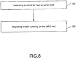
- a method of making an airfoil for a gas turbine engine is depicted.
- An airfoil is machined to have an airfoil root.
- a wear covering is disposed onto the airfoil root.
- the airfoil root is as herein described.
- the wear covering is a composite laminate layer.
- the composite laminate layer is an integrally bonded woven laminate containing a mixture of polytetrafluoroethylene and poly-meta-phenylene isophthalamide fibers arranged in an inverse fashion to produce a right angle grid.
- the method of making an airfoil root includes treating the airfoil root to produce a compressive residual stress layer.
- the compressive residual stress layer is achieved by burnishing the airfoil root.
- compressive residual stress layer refers to a stress layer imparted into an airfoil root by a process modifying the mechanical properties of the airfoil root.
- the compressive residual stress layer is not a layer of stress inherent in the airfoil root, but is added to the airfoil root by an additional process applied to the material of the airfoil root.
- a gas turbine engine constructed in accordance with the present disclosure is generally referred to by reference numeral 10.
- the engine 10 includes from fore-to-aft, a fan 20, a compressor 22, a combustor 24, a turbine 26, known as the engine core 28, lying along a central longitudinal axis 40, and surrounded by an engine core cowl 30.
- the compressor 22 is connected to the turbine 26 via a central rotating shaft 32.
- the engine 10 is depicted as a multi-spool engine design.
- Plural turbines sections 26 are connected to, and drive, corresponding plural sections of the compressor 22 and a fan 20 via the central rotating shaft 32 and a concentric rotating shaft 34, enabling increased compression efficiency.
- the fan 20 includes a disc rotor 50 having multiple slots 52 disposed around the circumference 51 of the disc rotor 50.
- the slots 52 are equally spaced around the circumference 51 of the disc rotor 50.
- a bearing aperture 54 running along the central longitudinal axis 40, is present where a central rotating shaft 32 or another connection can fit the fan 20 to the power generation unit of the gas turbine engine 10.
- each fan blade includes a blade section 62 and a root 70.
- the root 70 may be dovetail in shape, with the slots 52 being complementarily formed to receive the dovetail root 70 in a secure fashion. Given this size and shape, the dovetail root 70 presses against the sides of the slots 52 due to centrifugal force when the disc rotor 50 spins around the central longitudinal axis 40. The slots 52 pressing against the dovetail root 70 therefore prevent the fan blade 60 from dislodging from the disc rotor 50 when the gas turbine engine 10 is in operation.
- the dovetail root 70 can be seen in more detail.
- the dovetail root 70 is formed from a metallic core 71, which may be an aluminum alloy.
- the dovetail root 70 has a first pressure face 72 and a second pressure face 74 angling outward from the vertical axis 80 of the dovetail root 70.
- a horizontal face 76 connects the first pressure face 72 to the second pressure face 74.
- a neck portion 73 extends upward from both the first pressure face 72 and the second pressure face 74 of the dovetail root 70, and attaches to the blade component 62 of the fan blade 60.
- a first runout fillet 78 is machined onto the first pressure face 72 of the dovetail root 70 so that it may fit into a slot 52 of the disc rotor 50.
- a second runout fillet 79 is machined onto the second pressure face 74 of the dovetail root 70 so that it may fit the same.
- the first runout fillet 78 and the second runout fillet 79 each travel the length of their respective pressure faces, and may be equal to each other in their size, shape and formation on the dovetail root 70.
- a compressive residual stress layer 90 is treated into the first runout fillet 78 and the second runout fillet 79 of the dovetail root 70. Treating the fillets 78 and 79 of the dovetail root 70 in such a way imparts the compressive residual stress layer 90 into the dovetail root 70.
- the treatment is performed by burnishment. To burnish the fillets 78 and 79 of the dovetail root 70, a heavy pressure is applied to the fillets 78 and 79 in a controlled manner such as using a roller(s) or the like.
- the wear covering 100 may envelop the length of the first runout fillet 78 of the first pressure face 72 as well as the second runout fillet 79 of the second pressure face 74 of the dovetail root 70. Additionally, the wear covering 100 can extend to envelop the neck portion 73 of the dovetail root 70 above both the first runout fillet 78 and the second runout fillet 79.
- the wear covering 100 envelops the dovetail root 70 in a precise geometric pattern over the dovetail root 70 so that the areas of the dovetail root 70 which press against the walls of the slot 52 are adequately protected when the disc rotor 50 rotates. Configuring the wear covering 100 in such a way prevents cracking and deformation of the dovetail root 70 when the gas turbine engine 10 is in operation. Additionally, the wear covering 100 protects the dovetail root 70 from handling damage when placing the dovetail root 70 into the slot 52 of the disc rotor 50.
- the dovetail root 70 is placed within one of the slots 52 of the disc rotor 50.
- the dovetail root 70 has already been treated and implanted with the compressive residual stress layer 90 described above.
- a wear covering 100 also as understood and described above, is affixed to the outside of the dovetail root 70 before placing the dovetail root 70 into the slot 52. Placing the dovetail root 70 into the slot 52 in this fashion and with the added protection of the compressive residual stress layer 90 and the wear covering 100 prevents cracking and deformation of the dovetail root 70 when the gas turbine engine 10 is in operation. Furthermore, reducing crack formation and deformation of the dovetail root 70 prevents the likelihood of the dovetail root 70 dislodging from the slot 52 of the disc rotor 50 when the gas turbine engine 10 is in operation.
- the wear covering 100 is depicted in greater detail in FIG. 7 . As illustrated, the wear covering 100 is bonded by an epoxy 120, adhesive or the like to the dovetail root 70. The wear covering 100 can be affixed to the metallic core 71 of the dovetail root 70 in other fashions including but not limited to scribing.
- the wear covering 100 is a composite laminate layer 110 made from integrally bonded woven laminate. The materials used to form the integrally bonded woven laminate are Teflon® (polytetrafluoroethylene) fibers 130 and Nomex® (poly-meta-phenylene isophthalamide) fibers 140. Polytetrafluoroethylene fibers 130 have a low coefficient of friction against solid masses.
- polytetrafluoroethylene fibers 130 reduce friction and wear when used on machinery.
- Poly-meta-phenylene isophthalamide fibers 140 are rigid and very durable. Additionally, poly-meta-phenylene isophthalamide fibers 140 have fire resistant qualities which allow the poly-meta-phenylene isophthalamide fibers 140 to hold up well in the extreme operation temperatures and conditions of a gas turbine engine 10. Furthermore, the polytetrafluoroethylene fibers 130 and the poly-meta-phenylene isophthalamide fibers 140 are arranged in an inverse fashion so as to produce a right angle grid. The wear covering 100 may then be epoxy bonded 120 onto the dovetail root 70.
- an airfoil or fan blade 60 is machined to have an airfoil root 70.
- a wear covering 100 is disposed on the of the airfoil root 70.
- the wear covering 100 is a composite laminate layer 110 made from integrally bonded woven laminate.
- the material used to form the integrally bonded woven laminate are polytetrafluoroethylene fibers 130 and poly-meta-phenylene isophthalamide fibers 140.
- the wear covering can be disposed on the airfoil root 70 by adhering it to the airfoil root 70 with an epoxy 120, other adhesive or the like. Disposing the wear covering 100 on the airfoil root 70 provides an addition layer of protection to guard the airfoil root 70 from crack initiation while a gas turbine engine 10 is in operation.
- the airfoil root 70 is treated to have a compressive residual stress layer 90. Treating the airfoil root or 70 to have a compressive residual stress layer 90 is done by burnishing the airfoil root 70.
- the compressive residual stress layer 90 aids in the prevention of crack initiation within the airfoil root 70 when a gas turbine engine 10 is in operation.
- the wear covering 100 may be disposed on the compressive residual stress layer 90 of the airfoil root 70.
- Figure 8 illustrates the significant improvement in strength achieved by the burnished dovetail root 70 of the present disclosure as opposed to a prior art polished dovetail root. If a metallic core is simply polished as with the prior art and placed into testing conditions, the resulting cycles to failure are shown in the bar chart to be roughly 225,000 cycles. If, however, the dovetail root 70 is treated to impart a compressive residual stress layer 90 into the metallic core 71 of the dovetail root 70 as with the prior art, the resulting cycles to failure can be dramatically increased. More specifically, the number of cycles to failure for such a burnished dovetail root 70 can be viewed with the bar representing stimulated deep burnished surface as roughly one million cycles. Comparing the two bars against one another it can be seen that the dovetail root 70 of the present disclosure lasts at least four times longer, if not greater, before failing in respect to a dovetail root having only a polished surface.
- dovetail roots disclosed herein may have industrial applicability in a variety of setting such as, but not limited to, use in a gas turbine engine environment. Such disclosed dovetail roots may also be used, for example, in aerospace or marine machines for generating thrust, or in industrial or mining applications for generating power.
- dovetail roots substantially avoid cracking or other fatigue related inconsistencies so as to provide a stronger and longer lasting blade and root.
- Use of the disclosed dovetail roots also allow for the production of more light weight and thus, more efficient gas turbine engines.
- roots are less susceptible to cracking, they are also less susceptible to dislodgement from the engine rotor.
Landscapes
- Engineering & Computer Science (AREA)
- Mechanical Engineering (AREA)
- General Engineering & Computer Science (AREA)
- Chemical & Material Sciences (AREA)
- Combustion & Propulsion (AREA)
- Structures Of Non-Positive Displacement Pumps (AREA)
Description
- The present disclosure generally relates to gas turbine engines, and more particularly to a fan blade root.
- Gas turbine engines are commonly used to generate energy and propulsion in many modern aircraft as well as other vehicles and industrial processes. Many such engines include a fan, compressor, combustor and turbine provided in serial fashion, forming an engine core and arranged along a central longitudinal axis. Air enters the gas turbine engine through the fan and is pressurized in the compressor. This pressurized air is mixed with fuel in the combustor. The fuel-air mixture is then ignited, generating hot combustion gases that flow downstream to the turbine. The turbine is driven by the exhaust gases and mechanically powers the compressor and fan via a central rotating shaft. Energy from the combustion gases not used by the turbine is discharged through an exhaust nozzle, producing thrust to power the aircraft.
- In light of this it can be seen that the airfoils of a gas turbine engine, including the fan, compressor, and turbine blades and vanes, are subjected to extreme internal temperatures and weather conditions when the gas turbine engine is in operation. Accordingly, such airfoils need to be manufactured well. This is important not only for efficient, proper operation, but for safe operation as well. For example, given the proximity of such engines to the fuselage of the aircraft, it is important that such blades remain connected to their respective rotor hubs, and in the rare event of dislodgement, that the blades be contained within the engine. In fact, the Federal Aviation Administration requires that gas turbine engines meet certain requirements in this regard and thus sets forth regulations, such as 14 C.F.R. §33.94, pertaining to blade containment.
- One situation, which may be particularly challenging for gas turbine engines in this regard, arises when the engine ingests foreign objects, such as birds or ice. The blades, in such a situation, must be manufactured sufficiently to withstand such impact, and absent that, the engine as a whole must be sufficiently designed to contain such blades if they should become dislodged.
- Therefore, it would be advantageous to produce a fan blade of sufficient strength and design to avoid dislodgement, even in the event of foreign object ingestion. Ideally, the fan blade would be designed and built strong enough to not only meet FAA requirements, but to far exceed them as well. Fan blades with improved wear are disclosed in
WO 2014/137438 which proposes polymeric mitigation wear pads on fan blade roots.EP 2955326 discloses a configuration with a reinforced ground path for turbine blades.US 2013/302173 discloses a wear resistant turbine fan blade having a composite lubricated sheet adhered to a root of the turbine fan blade. - In accordance with one aspect of the disclosure, a fan blade has an airfoil component and an airfoil root. The airfoil root is formed having a core. A wear covering is disposed onto the core of the airfoil root. The wear covering is a composite laminate layer. The composite laminate layer is an integrally bonded woven laminate containing a mixture of polytetrafluoroethylene and poly-meta-phenylene isophthalamide fibers arranged in an inverse fashion to produce a right angle grid. A compressive residual stress layer is treated into the core of the airfoil root. The compressive residual stress layer is produced by burnishing the core of the airfoil root.
- In an additional and/or alternative embodiment, the wear covering is adhered to the compressive residual stress layer by an epoxy bond.
- In an additional and/or alternative embodiment of any of the foregoing embodiment, the core of the airfoil root has a first pressure face and a second pressure face angled outward from a vertical axis of the core, a first runout fillet disposed into and traveling the length of the first pressure face and a second runout fillet disposed into and traveling the length of the second pressure face, a horizontal face connecting the first pressure face to the second pressure face located at a bottom of the core, and a neck portion extending above the first pressure face and the second pressure face.
- In an additional and/or alternative embodiment of any of the foregoing embodiments, the wear covering is adhered to the first runout fillet and the second runout fillet of the core.
- In an additional and/or alternative embodiment of any of the foregoing embodiments, the wear covering is adhered to the neck portion of the core.
- In an additional and/or alternative embodiment of any of the foregoing embodiments, a compressive residual stress layer is treated into the first runout fillet and the second runout fillet of the core.
- In accordance with another aspect of the disclosure, a gas turbine engine is formed having a fan, a compressor downstream of the fan, a combustor downstream of the compressor, and a turbine downstream of the combustor. The fan has a plurality of fan blades connected to a rotor. The plurality of fan blades each have an airfoil component and an airfoil root as herein described. The airfoil root has a core and a wear covering adhered to the core of the airfoil root. The wear covering is a composite laminate layer. The composite laminate layer is an integrally bonded woven laminate containing a mixture of polytetrafluoroethylene and poly-meta-phenylene isophthalamide fibers arranged in an inverse fashion to produce a right angle grid. A compressive residual stress layer is treated into the core of the airfoil root. The compressive residual stress layer is produced by burnishing the core of the airfoil root.
- In an additional and/or alternative embodiment of any of the foregoing embodiments, the wear covering disposed onto the core of the airfoil root is adhered to the compressive residual stress layer by an epoxy bond.
- In an additional and/or alternative embodiment of any of the foregoing embodiments, the core of the airfoil root has a first pressure face and a second pressure face angled outward from a vertical axis of the core, a first runout fillet disposed into and traveling the length of the first pressure face and a second runout fillet disposed into and traveling the length of the second pressure face, a horizontal face connecting the first pressure face to the second pressure face located at a bottom of the core, and a neck portion extending above the first pressure face and the second pressure face. In an additional and/or alternative embodiment of any of the foregoing embodiments, the airfoil root has a first pressure face and a second pressure face angled outward from a vertical axis of the airfoil root, a first runout fillet disposed into and traveling the length of the first pressure face and a second runout fillet disposed into and traveling the length of the second pressure face, a horizontal face connecting the first pressure face to the second pressure face located at a bottom of the airfoil root, and a neck portion extending above the first pressure face and the second pressure face.
- In an additional and/or alternative embodiment of any of the foregoing embodiments, the wear covering is adhered to the first runout fillet and the second runout fillet of the core of the airfoil root. In an additional and/or alternative embodiment of any of the foregoing embodiments, the wear covering is adhered to the first runout fillet and the second runout fillet of the airfoil root.
- In an additional and/or alternative embodiment of any of the foregoing embodiments, the wear covering is adhered to the neck portion of the core of the airfoil root. In an additional and/or alternative embodiment of any of the foregoing embodiments, the wear covering is adhered to the neck portion of the airfoil root.
- In an additional and/or alternative embodiment of any of the foregoing embodiments, the compressive residual stress layer provided in the core of the airfoil root is treated into the first runout fillet and the second runout fillet of the core. In an additional and/or alternative embodiment of any of the foregoing embodiments, a compressive residual stress layer is treated into the first runout fillet and the second runout fillet of the airfoil root.
- In accordance with another aspect of the disclosure, a method of making an airfoil for a gas turbine engine is depicted. An airfoil is machined to have an airfoil root. Then, a wear covering is disposed onto the airfoil root. Preferably the airfoil root is as herein described. The wear covering is a composite laminate layer. The composite laminate layer is an integrally bonded woven laminate containing a mixture of polytetrafluoroethylene and poly-meta-phenylene isophthalamide fibers arranged in an inverse fashion to produce a right angle grid. The method of making an airfoil root includes treating the airfoil root to produce a compressive residual stress layer. The compressive residual stress layer is achieved by burnishing the airfoil root.
- These and other aspects and features will be better understood when taken in conjunction with the following drawings.
-
-
Figure 1 is a cross-sectional view of a gas turbine engine constructed in accordance with the teachings of the present disclosure. -
Figure 2 is a perspective view of a fan blade inserted into a disc rotor of a gas turbine engine in accordance with the present disclosure. -
Figure 3 is an enlarged view of a dovetail root section of a fan blade constructed in accordance with the present disclosure and shown angled to the right. -
Figure 4 is an enlarged view of a dovetail root section of a fan blade constructed in accordance with the present disclosure and shown angled to the left. -
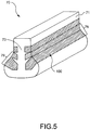
Figure 5 is an elongated cross-sectional view of a dovetail root of a fan blade in accordance with the present disclosure showing placement of a wear covering on the dovetail root. -
Figure 6 is a cross-sectional view of a dovetail root of a fan blade in accordance with the present disclosure, showing placement of a wear covering on the dovetail root when the dovetail root is placed in a disc rotor of a gas turbine fan engine. -
Figure 7 is an enlarged cross-section of area 7 fromFigure 6 showing a wear covering in accordance with the present disclosure attached to the dovetail root. -
Figure 8 is a flowchart that exemplifies one method of making the disclosed dovetail root in accordance with the present disclosure. -
Figure 9 is a graph that exemplifies the approximate number of cycles to failure of a prior art dovetail root in comparison to a dovetail root in accordance with the present disclosure. - It should be understood that the drawings are not necessarily to scale and that the disclosed embodiments are illustrated diagrammatically and in partial views. It should be further understood that this disclosure is not to be limited to the particular embodiments illustrated herein.
- To facilitate a better understanding of the invention, terms and phrases are defined below:
- As used herein, the term "compressive residual stress layer" refers to a stress layer imparted into an airfoil root by a process modifying the mechanical properties of the airfoil root. The compressive residual stress layer is not a layer of stress inherent in the airfoil root, but is added to the airfoil root by an additional process applied to the material of the airfoil root.
- Referring now to the drawings and with specific reference to
FIG. 1 , a gas turbine engine constructed in accordance with the present disclosure is generally referred to byreference numeral 10. As illustrated, theengine 10, includes from fore-to-aft, afan 20, acompressor 22, acombustor 24, aturbine 26, known as theengine core 28, lying along a centrallongitudinal axis 40, and surrounded by anengine core cowl 30. Thecompressor 22 is connected to theturbine 26 via a centralrotating shaft 32. More specifically, theengine 10, is depicted as a multi-spool engine design.Plural turbines sections 26 are connected to, and drive, corresponding plural sections of thecompressor 22 and afan 20 via the centralrotating shaft 32 and a concentricrotating shaft 34, enabling increased compression efficiency. - Ambient air enters the
compressor 22 at aninlet 36, is pressurized, and is then directed to thecombustor 24, mixed with fuel and combusted. This generates combustion gases that flow downstream to theturbine 26, which extracts kinetic energy from the exhausted combustion gases. Theturbine 26, via the centralrotating shaft 32 andconcentric rotation shaft 34, drives thecompressor 22 and thefan 20, which draws in ambient air. Thrust is produced both by ambient air accelerated aft by thefan 20 and by exhaust gasses exiting from theengine core 28. While the depicted embodiment is described as a multi-spool type of gas turbine engine, it is to be understood that the teachings of the present disclosure are not limited in application to the depicted embodiment of a gas turbine engine, but rather should be employed with equal efficacy. - Referring now to
FIG. 2 , thefan 20 is shown in greater detail. More specifically, thefan 20 includes adisc rotor 50 havingmultiple slots 52 disposed around thecircumference 51 of thedisc rotor 50. Theslots 52 are equally spaced around thecircumference 51 of thedisc rotor 50. In the center of thedisc rotor 50, a bearingaperture 54, running along the centrallongitudinal axis 40, is present where a centralrotating shaft 32 or another connection can fit thefan 20 to the power generation unit of thegas turbine engine 10. - Radially extending from the
rotor 50, a plurality offan blades 60 are provided. As will be noted, each fan blade includes ablade section 62 and aroot 70. Theroot 70 may be dovetail in shape, with theslots 52 being complementarily formed to receive thedovetail root 70 in a secure fashion. Given this size and shape, thedovetail root 70 presses against the sides of theslots 52 due to centrifugal force when thedisc rotor 50 spins around the centrallongitudinal axis 40. Theslots 52 pressing against thedovetail root 70 therefore prevent thefan blade 60 from dislodging from thedisc rotor 50 when thegas turbine engine 10 is in operation. - Viewing
FIGS. 3 and 4 , thedovetail root 70 can be seen in more detail. Thedovetail root 70 is formed from ametallic core 71, which may be an aluminum alloy. Thedovetail root 70 has afirst pressure face 72 and asecond pressure face 74 angling outward from thevertical axis 80 of thedovetail root 70. At the bottom of thedovetail root 70, a horizontal face 76 connects thefirst pressure face 72 to thesecond pressure face 74. Aneck portion 73 extends upward from both thefirst pressure face 72 and thesecond pressure face 74 of thedovetail root 70, and attaches to theblade component 62 of thefan blade 60. - A
first runout fillet 78 is machined onto thefirst pressure face 72 of thedovetail root 70 so that it may fit into aslot 52 of thedisc rotor 50. Likewise, asecond runout fillet 79 is machined onto thesecond pressure face 74 of thedovetail root 70 so that it may fit the same. Thefirst runout fillet 78 and thesecond runout fillet 79 each travel the length of their respective pressure faces, and may be equal to each other in their size, shape and formation on thedovetail root 70. - In order to achieve the desired
dovetail root 70, a compressiveresidual stress layer 90 is treated into thefirst runout fillet 78 and thesecond runout fillet 79 of thedovetail root 70. Treating thefillets dovetail root 70 in such a way imparts the compressiveresidual stress layer 90 into thedovetail root 70. The treatment is performed by burnishment. To burnish thefillets dovetail root 70, a heavy pressure is applied to thefillets - Referring now to
FIG. 5 , another way the desireddovetail root 70 is achieved is by disposing a wear covering 100 on thedovetail root 70. The wear covering 100 may envelop the length of thefirst runout fillet 78 of thefirst pressure face 72 as well as thesecond runout fillet 79 of thesecond pressure face 74 of thedovetail root 70. Additionally, the wear covering 100 can extend to envelop theneck portion 73 of thedovetail root 70 above both thefirst runout fillet 78 and thesecond runout fillet 79. The wear covering 100 envelops thedovetail root 70 in a precise geometric pattern over thedovetail root 70 so that the areas of thedovetail root 70 which press against the walls of theslot 52 are adequately protected when thedisc rotor 50 rotates. Configuring the wear covering 100 in such a way prevents cracking and deformation of thedovetail root 70 when thegas turbine engine 10 is in operation. Additionally, the wear covering 100 protects thedovetail root 70 from handling damage when placing thedovetail root 70 into theslot 52 of thedisc rotor 50. - As illustrated in
FIG. 6 , thedovetail root 70 is placed within one of theslots 52 of thedisc rotor 50. As will be understood, thedovetail root 70 has already been treated and implanted with the compressiveresidual stress layer 90 described above. A wear covering 100, also as understood and described above, is affixed to the outside of thedovetail root 70 before placing thedovetail root 70 into theslot 52. Placing thedovetail root 70 into theslot 52 in this fashion and with the added protection of the compressiveresidual stress layer 90 and the wear covering 100 prevents cracking and deformation of thedovetail root 70 when thegas turbine engine 10 is in operation. Furthermore, reducing crack formation and deformation of thedovetail root 70 prevents the likelihood of thedovetail root 70 dislodging from theslot 52 of thedisc rotor 50 when thegas turbine engine 10 is in operation. - The wear covering 100 is depicted in greater detail in
FIG. 7 . As illustrated, the wear covering 100 is bonded by an epoxy 120, adhesive or the like to thedovetail root 70. The wear covering 100 can be affixed to themetallic core 71 of thedovetail root 70 in other fashions including but not limited to scribing. The wear covering 100 is acomposite laminate layer 110 made from integrally bonded woven laminate. The materials used to form the integrally bonded woven laminate are Teflon® (polytetrafluoroethylene)fibers 130 and Nomex® (poly-meta-phenylene isophthalamide)fibers 140.Polytetrafluoroethylene fibers 130 have a low coefficient of friction against solid masses. Because of this,polytetrafluoroethylene fibers 130 reduce friction and wear when used on machinery. Poly-meta-phenylene isophthalamide fibers 140 are rigid and very durable. Additionally, poly-meta-phenylene isophthalamide fibers 140 have fire resistant qualities which allow the poly-meta-phenylene isophthalamide fibers 140 to hold up well in the extreme operation temperatures and conditions of agas turbine engine 10. Furthermore, thepolytetrafluoroethylene fibers 130 and the poly-meta-phenylene isophthalamide fibers 140 are arranged in an inverse fashion so as to produce a right angle grid. The wear covering 100 may then be epoxy bonded 120 onto thedovetail root 70. - Referring now to
Fig. 8 , an exemplary succession of steps which may be used to produce an airfoil orfan blade 60 for agas turbine engine 10 in accordance with the present disclosure are shown. Starting withblock 150, an airfoil orfan blade 60, is machined to have anairfoil root 70. Then, as illustrated byblock 160, a wear covering 100 is disposed on the of theairfoil root 70. The wear covering 100 is acomposite laminate layer 110 made from integrally bonded woven laminate. The material used to form the integrally bonded woven laminate arepolytetrafluoroethylene fibers 130 and poly-meta-phenylene isophthalamide fibers 140. Additionally the wear covering can be disposed on theairfoil root 70 by adhering it to theairfoil root 70 with an epoxy 120, other adhesive or the like. Disposing the wear covering 100 on theairfoil root 70 provides an addition layer of protection to guard theairfoil root 70 from crack initiation while agas turbine engine 10 is in operation. Theairfoil root 70 is treated to have a compressiveresidual stress layer 90. Treating the airfoil root or 70 to have a compressiveresidual stress layer 90 is done by burnishing theairfoil root 70. The compressiveresidual stress layer 90 aids in the prevention of crack initiation within theairfoil root 70 when agas turbine engine 10 is in operation. Furthermore, the wear covering 100 may be disposed on the compressiveresidual stress layer 90 of theairfoil root 70. - Graphically,
Figure 8 illustrates the significant improvement in strength achieved by the burnisheddovetail root 70 of the present disclosure as opposed to a prior art polished dovetail root. If a metallic core is simply polished as with the prior art and placed into testing conditions, the resulting cycles to failure are shown in the bar chart to be roughly 225,000 cycles. If, however, thedovetail root 70 is treated to impart a compressiveresidual stress layer 90 into themetallic core 71 of thedovetail root 70 as with the prior art, the resulting cycles to failure can be dramatically increased. More specifically, the number of cycles to failure for such aburnished dovetail root 70 can be viewed with the bar representing stimulated deep burnished surface as roughly one million cycles. Comparing the two bars against one another it can be seen that thedovetail root 70 of the present disclosure lasts at least four times longer, if not greater, before failing in respect to a dovetail root having only a polished surface. - From the foregoing, it may be appreciated that the dovetail roots disclosed herein may have industrial applicability in a variety of setting such as, but not limited to, use in a gas turbine engine environment. Such disclosed dovetail roots may also be used, for example, in aerospace or marine machines for generating thrust, or in industrial or mining applications for generating power.
- Additionally in the field of gas turbine engines for aviation, such dovetail roots substantially avoid cracking or other fatigue related inconsistencies so as to provide a stronger and longer lasting blade and root. Use of the disclosed dovetail roots also allow for the production of more light weight and thus, more efficient gas turbine engines. Moreover, as such roots are less susceptible to cracking, they are also less susceptible to dislodgement from the engine rotor.
Claims (8)
- A fan blade having an airfoil component (60) and an airfoil root (70), the airfoil root (70), comprising:a core (71); anda wear covering (100) disposed onto the core (71);characterised in that said wear covering (100) is a composite laminate layer (110),wherein the composite laminate layer (110) is an integrally bonded woven laminate containing a mixture of polytetrafluoroethylene (130) and poly-meta-phenylene isophthalamide (140) fibers arranged in an inverse fashion to produce a right angle grid,wherein the airfoil root further includes a compressive residual stress layer (90) treated into the core (71), the compressive residual stress layer (90) being produced by a burnishing of the core.
- The fan blade according to claim 1, wherein the wear covering (100) is adhered to the compressive residual stress layer (90) by an epoxy bond.
- The fan blade according to claim 1 or claim 2, wherein the core (71) has a first pressure face (72) and a second pressure face (74) angled outward from a vertical axis (80) of the core (71), a first runout fillet (78) disposed into and traveling the length of the first pressure face (72) and a second runout fillet (79) disposed into and traveling the length of the second pressure face (74), a horizontal face (76) connecting the first pressure face (72) to the second pressure face (74) located at a bottom of the core (71), and a neck portion (73) extending above the first pressure face (72) and the second pressure face (74).
- The fan blade according to claim 3, wherein the wear covering (100) is adhered to the first runout fillet (78) and the second runout fillet (79) of the core (71).
- The fan blade according to claim 3 or claim 4, wherein the wear covering (100) is adhered to the neck portion (73) of the core (71).
- The fan blade according to any one of claims 3 to 5, wherein the compressive residual stress layer (90) is treated into the first runout fillet (78) and the second runout fillet (79) of the core (71).
- A gas turbine engine (10), comprising:a fan (20) having a plurality of fan blades (60) connected to a rotor (50), the plurality of fan blades (60) each having an airfoil component (60) and an airfoil root (70) according to any one of the preceding claims;a compressor (22) downstream of the fan (20);a combustor (24) downstream of the compressor (22); anda turbine (26) downstream of the combustor (24).
- A method of making an airfoil for a gas turbine engine (10), the method comprising:machining the airfoil to have an airfoil root (70); anddisposing a wear covering (100) on the airfoil root (70),characterised in that said wear covering (100) is a composite laminate layer (110), wherein the composite laminate layer (110) is an integrally bonded woven laminate containing a mixture of polytetrafluoroethylene (130) and poly-meta-phenylene isophthalamide (140) fibers arranged in an inverse fashion to produce a right angle grid,wherein said method further includes treating the airfoil root (70) to have a compressive residual stress layer (90), the compressive residual stress layer (90) being achieved by burnishing the airfoil root (70).
Applications Claiming Priority (1)
| Application Number | Priority Date | Filing Date | Title |
|---|---|---|---|
| US14/617,614 US10570755B2 (en) | 2015-02-09 | 2015-02-09 | Fan blade root |
Publications (2)
| Publication Number | Publication Date |
|---|---|
| EP3054097A1 EP3054097A1 (en) | 2016-08-10 |
| EP3054097B1 true EP3054097B1 (en) | 2019-09-18 |
Family
ID=55304917
Family Applications (1)
| Application Number | Title | Priority Date | Filing Date |
|---|---|---|---|
| EP16154415.0A Active EP3054097B1 (en) | 2015-02-09 | 2016-02-05 | Fan blade |
Country Status (2)
| Country | Link |
|---|---|
| US (1) | US10570755B2 (en) |
| EP (1) | EP3054097B1 (en) |
Families Citing this family (2)
| Publication number | Priority date | Publication date | Assignee | Title |
|---|---|---|---|---|
| US11454118B2 (en) * | 2020-09-04 | 2022-09-27 | General Electric Company | Gas turbine engine rotor blade having a root section with composite and metallic portions |
| US12123321B2 (en) * | 2022-12-27 | 2024-10-22 | General Electric Company | Composite airfoil assembly having a dovetail portion |
Citations (2)
| Publication number | Priority date | Publication date | Assignee | Title |
|---|---|---|---|---|
| EP1555329A1 (en) * | 2004-01-15 | 2005-07-20 | Siemens Aktiengesellschaft | Workpiece with internal compressive stresses, method and apparatus for producing internal compressive stresses |
| US20130302173A1 (en) * | 2012-05-11 | 2013-11-14 | E. I. Du Pont De Nemours And Company | Wear resistant turbine fan blade |
Family Cites Families (9)
| Publication number | Priority date | Publication date | Assignee | Title |
|---|---|---|---|---|
| US5522706A (en) | 1994-10-06 | 1996-06-04 | General Electric Company | Laser shock peened disks with loading and locking slots for turbomachinery |
| US8721294B2 (en) * | 2010-05-20 | 2014-05-13 | United Technologies Corporation | Airfoil with galvanically isolated metal coating |
| US20130004327A1 (en) | 2011-06-30 | 2013-01-03 | United Technologies Corporation | Aluminum fan blade root |
| US8443706B2 (en) * | 2011-09-07 | 2013-05-21 | E I Du Pont De Nemours And Company | Triaxial braid fabric architectures for improved soft body armor ballistic impact performance |
| WO2014137438A1 (en) | 2013-03-07 | 2014-09-12 | United Technologies Corporation | Aluminum fan blades with root wear mitigation |
| WO2014164859A2 (en) | 2013-03-11 | 2014-10-09 | Rolls-Royce Corporation | Compliant layer for ceramic components and methods of forming the same |
| US10415402B2 (en) | 2013-03-13 | 2019-09-17 | United Technologies Corporation | Blade wear pads and manufacture methods |
| DE102014206758A1 (en) | 2014-04-08 | 2015-10-08 | Siemens Aktiengesellschaft | Gas turbine blade or compressor blade with anti-fretting coating in the blade root area and rotor |
| US10107105B2 (en) | 2014-06-11 | 2018-10-23 | United Technologies Corporation | Fan blade grounding tab |
-
2015
- 2015-02-09 US US14/617,614 patent/US10570755B2/en active Active
-
2016
- 2016-02-05 EP EP16154415.0A patent/EP3054097B1/en active Active
Patent Citations (2)
| Publication number | Priority date | Publication date | Assignee | Title |
|---|---|---|---|---|
| EP1555329A1 (en) * | 2004-01-15 | 2005-07-20 | Siemens Aktiengesellschaft | Workpiece with internal compressive stresses, method and apparatus for producing internal compressive stresses |
| US20130302173A1 (en) * | 2012-05-11 | 2013-11-14 | E. I. Du Pont De Nemours And Company | Wear resistant turbine fan blade |
Also Published As
| Publication number | Publication date |
|---|---|
| US10570755B2 (en) | 2020-02-25 |
| EP3054097A1 (en) | 2016-08-10 |
| US20160230572A1 (en) | 2016-08-11 |
Similar Documents
| Publication | Publication Date | Title |
|---|---|---|
| US8029231B2 (en) | Fan track liner assembly | |
| JP6302251B2 (en) | System and method for composite blade with fillet transition | |
| EP2348192B1 (en) | Fan airfoil sheath | |
| EP2959108B1 (en) | Gas turbine engine having a mistuned stage | |
| US7887299B2 (en) | Rotary body for turbo machinery with mistuned blades | |
| US20030129061A1 (en) | Multi-component hybrid turbine blade | |
| US7018168B2 (en) | Method and apparatus for fabricating gas turbine engines | |
| US20200011203A1 (en) | Blade containment structure | |
| US10030522B2 (en) | Blade with metallic leading edge and angled shear zones | |
| US20160032729A1 (en) | Composite Fan Blade | |
| JP2000337294A (en) | Stress relief of blade support structure | |
| US10337521B2 (en) | Fan blade with integrated composite fan blade cover | |
| EP3049635B1 (en) | Aluminum airfoil with titanium coating | |
| EP3054097B1 (en) | Fan blade | |
| US20190218920A1 (en) | Blade for a gas turbine engine | |
| US10273816B2 (en) | Wear pad to prevent cracking of fan blade | |
| US11879354B2 (en) | Rotor blade with frangible spar for a gas turbine engine | |
| EP2472064A2 (en) | Airfoil for gas turbine engine | |
| US20170023006A1 (en) | Fan blade with composite cover and structural filler | |
| US12049848B2 (en) | Planetary gearbox and gas turbine engine having planetary gearbox | |
| US10995631B2 (en) | Method of shedding ice and fan blade | |
| WO2014096840A1 (en) | An aerofoil structure with tip portion cutting edges | |
| CN116292398A (en) | Rotatable airfoil parts with tiny rods | |
| US20250334050A1 (en) | Rotor Blade with Frangible Spar for a Gas Turbine Engine |
Legal Events
| Date | Code | Title | Description |
|---|---|---|---|
| PUAI | Public reference made under article 153(3) epc to a published international application that has entered the european phase |
Free format text: ORIGINAL CODE: 0009012 |
|
| AK | Designated contracting states |
Kind code of ref document: A1 Designated state(s): AL AT BE BG CH CY CZ DE DK EE ES FI FR GB GR HR HU IE IS IT LI LT LU LV MC MK MT NL NO PL PT RO RS SE SI SK SM TR |
|
| AX | Request for extension of the european patent |
Extension state: BA ME |
|
| RAP1 | Party data changed (applicant data changed or rights of an application transferred) |
Owner name: UNITED TECHNOLOGIES CORPORATION |
|
| STAA | Information on the status of an ep patent application or granted ep patent |
Free format text: STATUS: REQUEST FOR EXAMINATION WAS MADE |
|
| 17P | Request for examination filed |
Effective date: 20170209 |
|
| RBV | Designated contracting states (corrected) |
Designated state(s): AL AT BE BG CH CY CZ DE DK EE ES FI FR GB GR HR HU IE IS IT LI LT LU LV MC MK MT NL NO PL PT RO RS SE SI SK SM TR |
|
| STAA | Information on the status of an ep patent application or granted ep patent |
Free format text: STATUS: EXAMINATION IS IN PROGRESS |
|
| 17Q | First examination report despatched |
Effective date: 20170627 |
|
| GRAP | Despatch of communication of intention to grant a patent |
Free format text: ORIGINAL CODE: EPIDOSNIGR1 |
|
| STAA | Information on the status of an ep patent application or granted ep patent |
Free format text: STATUS: GRANT OF PATENT IS INTENDED |
|
| INTG | Intention to grant announced |
Effective date: 20190328 |
|
| GRAS | Grant fee paid |
Free format text: ORIGINAL CODE: EPIDOSNIGR3 |
|
| GRAA | (expected) grant |
Free format text: ORIGINAL CODE: 0009210 |
|
| STAA | Information on the status of an ep patent application or granted ep patent |
Free format text: STATUS: THE PATENT HAS BEEN GRANTED |
|
| AK | Designated contracting states |
Kind code of ref document: B1 Designated state(s): AL AT BE BG CH CY CZ DE DK EE ES FI FR GB GR HR HU IE IS IT LI LT LU LV MC MK MT NL NO PL PT RO RS SE SI SK SM TR |
|
| REG | Reference to a national code |
Ref country code: GB Ref legal event code: FG4D |
|
| REG | Reference to a national code |
Ref country code: CH Ref legal event code: EP |
|
| REG | Reference to a national code |
Ref country code: DE Ref legal event code: R096 Ref document number: 602016020669 Country of ref document: DE |
|
| REG | Reference to a national code |
Ref country code: AT Ref legal event code: REF Ref document number: 1181543 Country of ref document: AT Kind code of ref document: T Effective date: 20191015 |
|
| REG | Reference to a national code |
Ref country code: IE Ref legal event code: FG4D |
|
| REG | Reference to a national code |
Ref country code: NL Ref legal event code: MP Effective date: 20190918 |
|
| PG25 | Lapsed in a contracting state [announced via postgrant information from national office to epo] |
Ref country code: HR Free format text: LAPSE BECAUSE OF FAILURE TO SUBMIT A TRANSLATION OF THE DESCRIPTION OR TO PAY THE FEE WITHIN THE PRESCRIBED TIME-LIMIT Effective date: 20190918 Ref country code: LT Free format text: LAPSE BECAUSE OF FAILURE TO SUBMIT A TRANSLATION OF THE DESCRIPTION OR TO PAY THE FEE WITHIN THE PRESCRIBED TIME-LIMIT Effective date: 20190918 Ref country code: SE Free format text: LAPSE BECAUSE OF FAILURE TO SUBMIT A TRANSLATION OF THE DESCRIPTION OR TO PAY THE FEE WITHIN THE PRESCRIBED TIME-LIMIT Effective date: 20190918 Ref country code: BG Free format text: LAPSE BECAUSE OF FAILURE TO SUBMIT A TRANSLATION OF THE DESCRIPTION OR TO PAY THE FEE WITHIN THE PRESCRIBED TIME-LIMIT Effective date: 20191218 Ref country code: FI Free format text: LAPSE BECAUSE OF FAILURE TO SUBMIT A TRANSLATION OF THE DESCRIPTION OR TO PAY THE FEE WITHIN THE PRESCRIBED TIME-LIMIT Effective date: 20190918 Ref country code: NO Free format text: LAPSE BECAUSE OF FAILURE TO SUBMIT A TRANSLATION OF THE DESCRIPTION OR TO PAY THE FEE WITHIN THE PRESCRIBED TIME-LIMIT Effective date: 20191218 |
|
| REG | Reference to a national code |
Ref country code: LT Ref legal event code: MG4D |
|
| PG25 | Lapsed in a contracting state [announced via postgrant information from national office to epo] |
Ref country code: RS Free format text: LAPSE BECAUSE OF FAILURE TO SUBMIT A TRANSLATION OF THE DESCRIPTION OR TO PAY THE FEE WITHIN THE PRESCRIBED TIME-LIMIT Effective date: 20190918 Ref country code: LV Free format text: LAPSE BECAUSE OF FAILURE TO SUBMIT A TRANSLATION OF THE DESCRIPTION OR TO PAY THE FEE WITHIN THE PRESCRIBED TIME-LIMIT Effective date: 20190918 Ref country code: AL Free format text: LAPSE BECAUSE OF FAILURE TO SUBMIT A TRANSLATION OF THE DESCRIPTION OR TO PAY THE FEE WITHIN THE PRESCRIBED TIME-LIMIT Effective date: 20190918 Ref country code: GR Free format text: LAPSE BECAUSE OF FAILURE TO SUBMIT A TRANSLATION OF THE DESCRIPTION OR TO PAY THE FEE WITHIN THE PRESCRIBED TIME-LIMIT Effective date: 20191219 |
|
| REG | Reference to a national code |
Ref country code: AT Ref legal event code: MK05 Ref document number: 1181543 Country of ref document: AT Kind code of ref document: T Effective date: 20190918 |
|
| PG25 | Lapsed in a contracting state [announced via postgrant information from national office to epo] |
Ref country code: IT Free format text: LAPSE BECAUSE OF FAILURE TO SUBMIT A TRANSLATION OF THE DESCRIPTION OR TO PAY THE FEE WITHIN THE PRESCRIBED TIME-LIMIT Effective date: 20190918 Ref country code: EE Free format text: LAPSE BECAUSE OF FAILURE TO SUBMIT A TRANSLATION OF THE DESCRIPTION OR TO PAY THE FEE WITHIN THE PRESCRIBED TIME-LIMIT Effective date: 20190918 Ref country code: NL Free format text: LAPSE BECAUSE OF FAILURE TO SUBMIT A TRANSLATION OF THE DESCRIPTION OR TO PAY THE FEE WITHIN THE PRESCRIBED TIME-LIMIT Effective date: 20190918 Ref country code: RO Free format text: LAPSE BECAUSE OF FAILURE TO SUBMIT A TRANSLATION OF THE DESCRIPTION OR TO PAY THE FEE WITHIN THE PRESCRIBED TIME-LIMIT Effective date: 20190918 Ref country code: ES Free format text: LAPSE BECAUSE OF FAILURE TO SUBMIT A TRANSLATION OF THE DESCRIPTION OR TO PAY THE FEE WITHIN THE PRESCRIBED TIME-LIMIT Effective date: 20190918 Ref country code: AT Free format text: LAPSE BECAUSE OF FAILURE TO SUBMIT A TRANSLATION OF THE DESCRIPTION OR TO PAY THE FEE WITHIN THE PRESCRIBED TIME-LIMIT Effective date: 20190918 Ref country code: PL Free format text: LAPSE BECAUSE OF FAILURE TO SUBMIT A TRANSLATION OF THE DESCRIPTION OR TO PAY THE FEE WITHIN THE PRESCRIBED TIME-LIMIT Effective date: 20190918 Ref country code: PT Free format text: LAPSE BECAUSE OF FAILURE TO SUBMIT A TRANSLATION OF THE DESCRIPTION OR TO PAY THE FEE WITHIN THE PRESCRIBED TIME-LIMIT Effective date: 20200120 |
|
| PG25 | Lapsed in a contracting state [announced via postgrant information from national office to epo] |
Ref country code: CZ Free format text: LAPSE BECAUSE OF FAILURE TO SUBMIT A TRANSLATION OF THE DESCRIPTION OR TO PAY THE FEE WITHIN THE PRESCRIBED TIME-LIMIT Effective date: 20190918 Ref country code: SK Free format text: LAPSE BECAUSE OF FAILURE TO SUBMIT A TRANSLATION OF THE DESCRIPTION OR TO PAY THE FEE WITHIN THE PRESCRIBED TIME-LIMIT Effective date: 20190918 Ref country code: IS Free format text: LAPSE BECAUSE OF FAILURE TO SUBMIT A TRANSLATION OF THE DESCRIPTION OR TO PAY THE FEE WITHIN THE PRESCRIBED TIME-LIMIT Effective date: 20200224 Ref country code: SM Free format text: LAPSE BECAUSE OF FAILURE TO SUBMIT A TRANSLATION OF THE DESCRIPTION OR TO PAY THE FEE WITHIN THE PRESCRIBED TIME-LIMIT Effective date: 20190918 |
|
| REG | Reference to a national code |
Ref country code: DE Ref legal event code: R097 Ref document number: 602016020669 Country of ref document: DE |
|
| PLBE | No opposition filed within time limit |
Free format text: ORIGINAL CODE: 0009261 |
|
| STAA | Information on the status of an ep patent application or granted ep patent |
Free format text: STATUS: NO OPPOSITION FILED WITHIN TIME LIMIT |
|
| PG2D | Information on lapse in contracting state deleted |
Ref country code: IS |
|
| PG25 | Lapsed in a contracting state [announced via postgrant information from national office to epo] |
Ref country code: DK Free format text: LAPSE BECAUSE OF FAILURE TO SUBMIT A TRANSLATION OF THE DESCRIPTION OR TO PAY THE FEE WITHIN THE PRESCRIBED TIME-LIMIT Effective date: 20190918 Ref country code: IS Free format text: LAPSE BECAUSE OF FAILURE TO SUBMIT A TRANSLATION OF THE DESCRIPTION OR TO PAY THE FEE WITHIN THE PRESCRIBED TIME-LIMIT Effective date: 20200119 |
|
| 26N | No opposition filed |
Effective date: 20200619 |
|
| PG25 | Lapsed in a contracting state [announced via postgrant information from national office to epo] |
Ref country code: SI Free format text: LAPSE BECAUSE OF FAILURE TO SUBMIT A TRANSLATION OF THE DESCRIPTION OR TO PAY THE FEE WITHIN THE PRESCRIBED TIME-LIMIT Effective date: 20190918 |
|
| REG | Reference to a national code |
Ref country code: CH Ref legal event code: PL |
|
| REG | Reference to a national code |
Ref country code: BE Ref legal event code: MM Effective date: 20200229 |
|
| PG25 | Lapsed in a contracting state [announced via postgrant information from national office to epo] |
Ref country code: LU Free format text: LAPSE BECAUSE OF NON-PAYMENT OF DUE FEES Effective date: 20200205 Ref country code: MC Free format text: LAPSE BECAUSE OF FAILURE TO SUBMIT A TRANSLATION OF THE DESCRIPTION OR TO PAY THE FEE WITHIN THE PRESCRIBED TIME-LIMIT Effective date: 20190918 |
|
| PG25 | Lapsed in a contracting state [announced via postgrant information from national office to epo] |
Ref country code: CH Free format text: LAPSE BECAUSE OF NON-PAYMENT OF DUE FEES Effective date: 20200229 Ref country code: LI Free format text: LAPSE BECAUSE OF NON-PAYMENT OF DUE FEES Effective date: 20200229 |
|
| PG25 | Lapsed in a contracting state [announced via postgrant information from national office to epo] |
Ref country code: IE Free format text: LAPSE BECAUSE OF NON-PAYMENT OF DUE FEES Effective date: 20200205 |
|
| PG25 | Lapsed in a contracting state [announced via postgrant information from national office to epo] |
Ref country code: BE Free format text: LAPSE BECAUSE OF NON-PAYMENT OF DUE FEES Effective date: 20200229 |
|
| PG25 | Lapsed in a contracting state [announced via postgrant information from national office to epo] |
Ref country code: TR Free format text: LAPSE BECAUSE OF FAILURE TO SUBMIT A TRANSLATION OF THE DESCRIPTION OR TO PAY THE FEE WITHIN THE PRESCRIBED TIME-LIMIT Effective date: 20190918 Ref country code: MT Free format text: LAPSE BECAUSE OF FAILURE TO SUBMIT A TRANSLATION OF THE DESCRIPTION OR TO PAY THE FEE WITHIN THE PRESCRIBED TIME-LIMIT Effective date: 20190918 Ref country code: CY Free format text: LAPSE BECAUSE OF FAILURE TO SUBMIT A TRANSLATION OF THE DESCRIPTION OR TO PAY THE FEE WITHIN THE PRESCRIBED TIME-LIMIT Effective date: 20190918 |
|
| PG25 | Lapsed in a contracting state [announced via postgrant information from national office to epo] |
Ref country code: MK Free format text: LAPSE BECAUSE OF FAILURE TO SUBMIT A TRANSLATION OF THE DESCRIPTION OR TO PAY THE FEE WITHIN THE PRESCRIBED TIME-LIMIT Effective date: 20190918 |
|
| REG | Reference to a national code |
Ref country code: DE Ref legal event code: R081 Ref document number: 602016020669 Country of ref document: DE Owner name: RAYTHEON TECHNOLOGIES CORPORATION (N.D.GES.D.S, US Free format text: FORMER OWNER: UNITED TECHNOLOGIES CORPORATION, FARMINGTON, CONN., US Ref country code: DE Ref legal event code: R081 Ref document number: 602016020669 Country of ref document: DE Owner name: RTX CORPORATION (N.D.GES.D. STAATES DELAWARE),, US Free format text: FORMER OWNER: UNITED TECHNOLOGIES CORPORATION, FARMINGTON, CONN., US |
|
| P01 | Opt-out of the competence of the unified patent court (upc) registered |
Effective date: 20230520 |
|
| PGFP | Annual fee paid to national office [announced via postgrant information from national office to epo] |
Ref country code: DE Payment date: 20250122 Year of fee payment: 10 |
|
| PGFP | Annual fee paid to national office [announced via postgrant information from national office to epo] |
Ref country code: FR Payment date: 20250121 Year of fee payment: 10 |
|
| PGFP | Annual fee paid to national office [announced via postgrant information from national office to epo] |
Ref country code: GB Payment date: 20250123 Year of fee payment: 10 |
|
| REG | Reference to a national code |
Ref country code: DE Ref legal event code: R081 Ref document number: 602016020669 Country of ref document: DE Owner name: RTX CORPORATION (N.D.GES.D. STAATES DELAWARE),, US Free format text: FORMER OWNER: RAYTHEON TECHNOLOGIES CORPORATION (N.D.GES.D.STAATES DELAWARE), ARLINGTON, VA, US |