EP3053835A1 - Forming assembly and method for forming a plurality of sealed packs for pourable food products starting from a tube of packaging material - Google Patents
Forming assembly and method for forming a plurality of sealed packs for pourable food products starting from a tube of packaging material Download PDFInfo
- Publication number
- EP3053835A1 EP3053835A1 EP15153730.5A EP15153730A EP3053835A1 EP 3053835 A1 EP3053835 A1 EP 3053835A1 EP 15153730 A EP15153730 A EP 15153730A EP 3053835 A1 EP3053835 A1 EP 3053835A1
- Authority
- EP
- European Patent Office
- Prior art keywords
- additional
- operative
- along
- shell
- sealing element
- Prior art date
- Legal status (The legal status is an assumption and is not a legal conclusion. Google has not performed a legal analysis and makes no representation as to the accuracy of the status listed.)
- Granted
Links
- 239000005022 packaging material Substances 0.000 title claims abstract description 23
- 238000000034 method Methods 0.000 title claims description 11
- 235000013305 food Nutrition 0.000 title description 12
- 238000007789 sealing Methods 0.000 claims abstract description 129
- 238000004806 packaging method and process Methods 0.000 claims description 15
- 230000015572 biosynthetic process Effects 0.000 claims description 11
- 238000011144 upstream manufacturing Methods 0.000 claims description 4
- 238000007599 discharging Methods 0.000 claims 1
- 239000000463 material Substances 0.000 description 10
- 230000000712 assembly Effects 0.000 description 9
- 238000000429 assembly Methods 0.000 description 9
- 238000005096 rolling process Methods 0.000 description 9
- 239000004033 plastic Substances 0.000 description 6
- 229920003023 plastic Polymers 0.000 description 6
- 230000005484 gravity Effects 0.000 description 4
- 238000010438 heat treatment Methods 0.000 description 3
- 239000004698 Polyethylene Substances 0.000 description 2
- 239000005030 aluminium foil Substances 0.000 description 2
- 239000013536 elastomeric material Substances 0.000 description 2
- 235000015203 fruit juice Nutrition 0.000 description 2
- 239000007788 liquid Substances 0.000 description 2
- 235000020191 long-life milk Nutrition 0.000 description 2
- -1 polyethylene Polymers 0.000 description 2
- 229920000573 polyethylene Polymers 0.000 description 2
- MHAJPDPJQMAIIY-UHFFFAOYSA-N Hydrogen peroxide Chemical compound OO MHAJPDPJQMAIIY-UHFFFAOYSA-N 0.000 description 1
- 235000007688 Lycopersicon esculentum Nutrition 0.000 description 1
- 240000003768 Solanum lycopersicum Species 0.000 description 1
- 125000004122 cyclic group Chemical group 0.000 description 1
- 238000006073 displacement reaction Methods 0.000 description 1
- 239000004715 ethylene vinyl alcohol Substances 0.000 description 1
- 239000002657 fibrous material Substances 0.000 description 1
- 235000013336 milk Nutrition 0.000 description 1
- 239000008267 milk Substances 0.000 description 1
- 210000004080 milk Anatomy 0.000 description 1
- 235000020200 pasteurised milk Nutrition 0.000 description 1
- 235000015067 sauces Nutrition 0.000 description 1
- 230000001954 sterilising effect Effects 0.000 description 1
- 238000004659 sterilization and disinfection Methods 0.000 description 1
- 239000003206 sterilizing agent Substances 0.000 description 1
- 239000000126 substance Substances 0.000 description 1
- 230000007704 transition Effects 0.000 description 1
- 235000014101 wine Nutrition 0.000 description 1
Images



Classifications
-
- B—PERFORMING OPERATIONS; TRANSPORTING
- B65—CONVEYING; PACKING; STORING; HANDLING THIN OR FILAMENTARY MATERIAL
- B65B—MACHINES, APPARATUS OR DEVICES FOR, OR METHODS OF, PACKAGING ARTICLES OR MATERIALS; UNPACKING
- B65B51/00—Devices for, or methods of, sealing or securing package folds or closures; Devices for gathering or twisting wrappers, or necks of bags
- B65B51/10—Applying or generating heat or pressure or combinations thereof
- B65B51/26—Devices specially adapted for producing transverse or longitudinal seams in webs or tubes
-
- B—PERFORMING OPERATIONS; TRANSPORTING
- B29—WORKING OF PLASTICS; WORKING OF SUBSTANCES IN A PLASTIC STATE IN GENERAL
- B29C—SHAPING OR JOINING OF PLASTICS; SHAPING OF MATERIAL IN A PLASTIC STATE, NOT OTHERWISE PROVIDED FOR; AFTER-TREATMENT OF THE SHAPED PRODUCTS, e.g. REPAIRING
- B29C65/00—Joining or sealing of preformed parts, e.g. welding of plastics materials; Apparatus therefor
- B29C65/02—Joining or sealing of preformed parts, e.g. welding of plastics materials; Apparatus therefor by heating, with or without pressure
-
- B—PERFORMING OPERATIONS; TRANSPORTING
- B29—WORKING OF PLASTICS; WORKING OF SUBSTANCES IN A PLASTIC STATE IN GENERAL
- B29C—SHAPING OR JOINING OF PLASTICS; SHAPING OF MATERIAL IN A PLASTIC STATE, NOT OTHERWISE PROVIDED FOR; AFTER-TREATMENT OF THE SHAPED PRODUCTS, e.g. REPAIRING
- B29C65/00—Joining or sealing of preformed parts, e.g. welding of plastics materials; Apparatus therefor
- B29C65/02—Joining or sealing of preformed parts, e.g. welding of plastics materials; Apparatus therefor by heating, with or without pressure
- B29C65/34—Joining or sealing of preformed parts, e.g. welding of plastics materials; Apparatus therefor by heating, with or without pressure using heated elements which remain in the joint, e.g. "verlorenes Schweisselement"
- B29C65/36—Joining or sealing of preformed parts, e.g. welding of plastics materials; Apparatus therefor by heating, with or without pressure using heated elements which remain in the joint, e.g. "verlorenes Schweisselement" heated by induction
- B29C65/3604—Joining or sealing of preformed parts, e.g. welding of plastics materials; Apparatus therefor by heating, with or without pressure using heated elements which remain in the joint, e.g. "verlorenes Schweisselement" heated by induction characterised by the type of elements heated by induction which remain in the joint
- B29C65/3656—Joining or sealing of preformed parts, e.g. welding of plastics materials; Apparatus therefor by heating, with or without pressure using heated elements which remain in the joint, e.g. "verlorenes Schweisselement" heated by induction characterised by the type of elements heated by induction which remain in the joint being a layer of a multilayer part to be joined, e.g. for joining plastic-metal laminates
-
- B—PERFORMING OPERATIONS; TRANSPORTING
- B29—WORKING OF PLASTICS; WORKING OF SUBSTANCES IN A PLASTIC STATE IN GENERAL
- B29C—SHAPING OR JOINING OF PLASTICS; SHAPING OF MATERIAL IN A PLASTIC STATE, NOT OTHERWISE PROVIDED FOR; AFTER-TREATMENT OF THE SHAPED PRODUCTS, e.g. REPAIRING
- B29C65/00—Joining or sealing of preformed parts, e.g. welding of plastics materials; Apparatus therefor
- B29C65/74—Joining or sealing of preformed parts, e.g. welding of plastics materials; Apparatus therefor by welding and severing, or by joining and severing, the severing being performed in the area to be joined, next to the area to be joined, in the joint area or next to the joint area
-
- B—PERFORMING OPERATIONS; TRANSPORTING
- B29—WORKING OF PLASTICS; WORKING OF SUBSTANCES IN A PLASTIC STATE IN GENERAL
- B29C—SHAPING OR JOINING OF PLASTICS; SHAPING OF MATERIAL IN A PLASTIC STATE, NOT OTHERWISE PROVIDED FOR; AFTER-TREATMENT OF THE SHAPED PRODUCTS, e.g. REPAIRING
- B29C65/00—Joining or sealing of preformed parts, e.g. welding of plastics materials; Apparatus therefor
- B29C65/74—Joining or sealing of preformed parts, e.g. welding of plastics materials; Apparatus therefor by welding and severing, or by joining and severing, the severing being performed in the area to be joined, next to the area to be joined, in the joint area or next to the joint area
- B29C65/745—Joining or sealing of preformed parts, e.g. welding of plastics materials; Apparatus therefor by welding and severing, or by joining and severing, the severing being performed in the area to be joined, next to the area to be joined, in the joint area or next to the joint area using a single unit having both a severing tool and a welding tool
- B29C65/7451—Joining or sealing of preformed parts, e.g. welding of plastics materials; Apparatus therefor by welding and severing, or by joining and severing, the severing being performed in the area to be joined, next to the area to be joined, in the joint area or next to the joint area using a single unit having both a severing tool and a welding tool the severing tool and the welding tool being movable with respect to one-another
-
- B—PERFORMING OPERATIONS; TRANSPORTING
- B29—WORKING OF PLASTICS; WORKING OF SUBSTANCES IN A PLASTIC STATE IN GENERAL
- B29C—SHAPING OR JOINING OF PLASTICS; SHAPING OF MATERIAL IN A PLASTIC STATE, NOT OTHERWISE PROVIDED FOR; AFTER-TREATMENT OF THE SHAPED PRODUCTS, e.g. REPAIRING
- B29C65/00—Joining or sealing of preformed parts, e.g. welding of plastics materials; Apparatus therefor
- B29C65/78—Means for handling the parts to be joined, e.g. for making containers or hollow articles, e.g. means for handling sheets, plates, web-like materials, tubular articles, hollow articles or elements to be joined therewith; Means for discharging the joined articles from the joining apparatus
- B29C65/7897—Means for discharging the joined articles from the joining apparatus
-
- B—PERFORMING OPERATIONS; TRANSPORTING
- B29—WORKING OF PLASTICS; WORKING OF SUBSTANCES IN A PLASTIC STATE IN GENERAL
- B29C—SHAPING OR JOINING OF PLASTICS; SHAPING OF MATERIAL IN A PLASTIC STATE, NOT OTHERWISE PROVIDED FOR; AFTER-TREATMENT OF THE SHAPED PRODUCTS, e.g. REPAIRING
- B29C66/00—General aspects of processes or apparatus for joining preformed parts
- B29C66/01—General aspects dealing with the joint area or with the area to be joined
- B29C66/05—Particular design of joint configurations
- B29C66/10—Particular design of joint configurations particular design of the joint cross-sections
- B29C66/11—Joint cross-sections comprising a single joint-segment, i.e. one of the parts to be joined comprising a single joint-segment in the joint cross-section
- B29C66/112—Single lapped joints
- B29C66/1122—Single lap to lap joints, i.e. overlap joints
-
- B—PERFORMING OPERATIONS; TRANSPORTING
- B29—WORKING OF PLASTICS; WORKING OF SUBSTANCES IN A PLASTIC STATE IN GENERAL
- B29C—SHAPING OR JOINING OF PLASTICS; SHAPING OF MATERIAL IN A PLASTIC STATE, NOT OTHERWISE PROVIDED FOR; AFTER-TREATMENT OF THE SHAPED PRODUCTS, e.g. REPAIRING
- B29C66/00—General aspects of processes or apparatus for joining preformed parts
- B29C66/40—General aspects of joining substantially flat articles, e.g. plates, sheets or web-like materials; Making flat seams in tubular or hollow articles; Joining single elements to substantially flat surfaces
- B29C66/41—Joining substantially flat articles ; Making flat seams in tubular or hollow articles
- B29C66/43—Joining a relatively small portion of the surface of said articles
- B29C66/431—Joining the articles to themselves
- B29C66/4312—Joining the articles to themselves for making flat seams in tubular or hollow articles, e.g. transversal seams
-
- B—PERFORMING OPERATIONS; TRANSPORTING
- B29—WORKING OF PLASTICS; WORKING OF SUBSTANCES IN A PLASTIC STATE IN GENERAL
- B29C—SHAPING OR JOINING OF PLASTICS; SHAPING OF MATERIAL IN A PLASTIC STATE, NOT OTHERWISE PROVIDED FOR; AFTER-TREATMENT OF THE SHAPED PRODUCTS, e.g. REPAIRING
- B29C66/00—General aspects of processes or apparatus for joining preformed parts
- B29C66/70—General aspects of processes or apparatus for joining preformed parts characterised by the composition, physical properties or the structure of the material of the parts to be joined; Joining with non-plastics material
- B29C66/72—General aspects of processes or apparatus for joining preformed parts characterised by the composition, physical properties or the structure of the material of the parts to be joined; Joining with non-plastics material characterised by the structure of the material of the parts to be joined
- B29C66/723—General aspects of processes or apparatus for joining preformed parts characterised by the composition, physical properties or the structure of the material of the parts to be joined; Joining with non-plastics material characterised by the structure of the material of the parts to be joined being multi-layered
- B29C66/7232—General aspects of processes or apparatus for joining preformed parts characterised by the composition, physical properties or the structure of the material of the parts to be joined; Joining with non-plastics material characterised by the structure of the material of the parts to be joined being multi-layered comprising a non-plastics layer
- B29C66/72321—General aspects of processes or apparatus for joining preformed parts characterised by the composition, physical properties or the structure of the material of the parts to be joined; Joining with non-plastics material characterised by the structure of the material of the parts to be joined being multi-layered comprising a non-plastics layer consisting of metals or their alloys
-
- B—PERFORMING OPERATIONS; TRANSPORTING
- B29—WORKING OF PLASTICS; WORKING OF SUBSTANCES IN A PLASTIC STATE IN GENERAL
- B29C—SHAPING OR JOINING OF PLASTICS; SHAPING OF MATERIAL IN A PLASTIC STATE, NOT OTHERWISE PROVIDED FOR; AFTER-TREATMENT OF THE SHAPED PRODUCTS, e.g. REPAIRING
- B29C66/00—General aspects of processes or apparatus for joining preformed parts
- B29C66/70—General aspects of processes or apparatus for joining preformed parts characterised by the composition, physical properties or the structure of the material of the parts to be joined; Joining with non-plastics material
- B29C66/72—General aspects of processes or apparatus for joining preformed parts characterised by the composition, physical properties or the structure of the material of the parts to be joined; Joining with non-plastics material characterised by the structure of the material of the parts to be joined
- B29C66/723—General aspects of processes or apparatus for joining preformed parts characterised by the composition, physical properties or the structure of the material of the parts to be joined; Joining with non-plastics material characterised by the structure of the material of the parts to be joined being multi-layered
- B29C66/7232—General aspects of processes or apparatus for joining preformed parts characterised by the composition, physical properties or the structure of the material of the parts to be joined; Joining with non-plastics material characterised by the structure of the material of the parts to be joined being multi-layered comprising a non-plastics layer
- B29C66/72327—General aspects of processes or apparatus for joining preformed parts characterised by the composition, physical properties or the structure of the material of the parts to be joined; Joining with non-plastics material characterised by the structure of the material of the parts to be joined being multi-layered comprising a non-plastics layer consisting of natural products or their composites, not provided for in B29C66/72321 - B29C66/72324
- B29C66/72328—Paper
-
- B—PERFORMING OPERATIONS; TRANSPORTING
- B29—WORKING OF PLASTICS; WORKING OF SUBSTANCES IN A PLASTIC STATE IN GENERAL
- B29C—SHAPING OR JOINING OF PLASTICS; SHAPING OF MATERIAL IN A PLASTIC STATE, NOT OTHERWISE PROVIDED FOR; AFTER-TREATMENT OF THE SHAPED PRODUCTS, e.g. REPAIRING
- B29C66/00—General aspects of processes or apparatus for joining preformed parts
- B29C66/70—General aspects of processes or apparatus for joining preformed parts characterised by the composition, physical properties or the structure of the material of the parts to be joined; Joining with non-plastics material
- B29C66/72—General aspects of processes or apparatus for joining preformed parts characterised by the composition, physical properties or the structure of the material of the parts to be joined; Joining with non-plastics material characterised by the structure of the material of the parts to be joined
- B29C66/723—General aspects of processes or apparatus for joining preformed parts characterised by the composition, physical properties or the structure of the material of the parts to be joined; Joining with non-plastics material characterised by the structure of the material of the parts to be joined being multi-layered
- B29C66/7234—General aspects of processes or apparatus for joining preformed parts characterised by the composition, physical properties or the structure of the material of the parts to be joined; Joining with non-plastics material characterised by the structure of the material of the parts to be joined being multi-layered comprising a barrier layer
- B29C66/72341—General aspects of processes or apparatus for joining preformed parts characterised by the composition, physical properties or the structure of the material of the parts to be joined; Joining with non-plastics material characterised by the structure of the material of the parts to be joined being multi-layered comprising a barrier layer for gases
-
- B—PERFORMING OPERATIONS; TRANSPORTING
- B29—WORKING OF PLASTICS; WORKING OF SUBSTANCES IN A PLASTIC STATE IN GENERAL
- B29C—SHAPING OR JOINING OF PLASTICS; SHAPING OF MATERIAL IN A PLASTIC STATE, NOT OTHERWISE PROVIDED FOR; AFTER-TREATMENT OF THE SHAPED PRODUCTS, e.g. REPAIRING
- B29C66/00—General aspects of processes or apparatus for joining preformed parts
- B29C66/70—General aspects of processes or apparatus for joining preformed parts characterised by the composition, physical properties or the structure of the material of the parts to be joined; Joining with non-plastics material
- B29C66/73—General aspects of processes or apparatus for joining preformed parts characterised by the composition, physical properties or the structure of the material of the parts to be joined; Joining with non-plastics material characterised by the intensive physical properties of the material of the parts to be joined, by the optical properties of the material of the parts to be joined, by the extensive physical properties of the parts to be joined, by the state of the material of the parts to be joined or by the material of the parts to be joined being a thermoplastic or a thermoset
- B29C66/739—General aspects of processes or apparatus for joining preformed parts characterised by the composition, physical properties or the structure of the material of the parts to be joined; Joining with non-plastics material characterised by the intensive physical properties of the material of the parts to be joined, by the optical properties of the material of the parts to be joined, by the extensive physical properties of the parts to be joined, by the state of the material of the parts to be joined or by the material of the parts to be joined being a thermoplastic or a thermoset characterised by the material of the parts to be joined being a thermoplastic or a thermoset
- B29C66/7392—General aspects of processes or apparatus for joining preformed parts characterised by the composition, physical properties or the structure of the material of the parts to be joined; Joining with non-plastics material characterised by the intensive physical properties of the material of the parts to be joined, by the optical properties of the material of the parts to be joined, by the extensive physical properties of the parts to be joined, by the state of the material of the parts to be joined or by the material of the parts to be joined being a thermoplastic or a thermoset characterised by the material of the parts to be joined being a thermoplastic or a thermoset characterised by the material of at least one of the parts being a thermoplastic
- B29C66/73921—General aspects of processes or apparatus for joining preformed parts characterised by the composition, physical properties or the structure of the material of the parts to be joined; Joining with non-plastics material characterised by the intensive physical properties of the material of the parts to be joined, by the optical properties of the material of the parts to be joined, by the extensive physical properties of the parts to be joined, by the state of the material of the parts to be joined or by the material of the parts to be joined being a thermoplastic or a thermoset characterised by the material of the parts to be joined being a thermoplastic or a thermoset characterised by the material of at least one of the parts being a thermoplastic characterised by the materials of both parts being thermoplastics
-
- B—PERFORMING OPERATIONS; TRANSPORTING
- B29—WORKING OF PLASTICS; WORKING OF SUBSTANCES IN A PLASTIC STATE IN GENERAL
- B29C—SHAPING OR JOINING OF PLASTICS; SHAPING OF MATERIAL IN A PLASTIC STATE, NOT OTHERWISE PROVIDED FOR; AFTER-TREATMENT OF THE SHAPED PRODUCTS, e.g. REPAIRING
- B29C66/00—General aspects of processes or apparatus for joining preformed parts
- B29C66/80—General aspects of machine operations or constructions and parts thereof
- B29C66/81—General aspects of the pressing elements, i.e. the elements applying pressure on the parts to be joined in the area to be joined, e.g. the welding jaws or clamps
- B29C66/814—General aspects of the pressing elements, i.e. the elements applying pressure on the parts to be joined in the area to be joined, e.g. the welding jaws or clamps characterised by the design of the pressing elements, e.g. of the welding jaws or clamps
- B29C66/8145—General aspects of the pressing elements, i.e. the elements applying pressure on the parts to be joined in the area to be joined, e.g. the welding jaws or clamps characterised by the design of the pressing elements, e.g. of the welding jaws or clamps characterised by the constructional aspects of the pressing elements, e.g. of the welding jaws or clamps
- B29C66/81457—General aspects of the pressing elements, i.e. the elements applying pressure on the parts to be joined in the area to be joined, e.g. the welding jaws or clamps characterised by the design of the pressing elements, e.g. of the welding jaws or clamps characterised by the constructional aspects of the pressing elements, e.g. of the welding jaws or clamps comprising a block or layer of deformable material, e.g. sponge, foam, rubber
-
- B—PERFORMING OPERATIONS; TRANSPORTING
- B29—WORKING OF PLASTICS; WORKING OF SUBSTANCES IN A PLASTIC STATE IN GENERAL
- B29C—SHAPING OR JOINING OF PLASTICS; SHAPING OF MATERIAL IN A PLASTIC STATE, NOT OTHERWISE PROVIDED FOR; AFTER-TREATMENT OF THE SHAPED PRODUCTS, e.g. REPAIRING
- B29C66/00—General aspects of processes or apparatus for joining preformed parts
- B29C66/80—General aspects of machine operations or constructions and parts thereof
- B29C66/82—Pressure application arrangements, e.g. transmission or actuating mechanisms for joining tools or clamps
- B29C66/822—Transmission mechanisms
- B29C66/8226—Cam mechanisms; Wedges; Eccentric mechanisms
- B29C66/82263—Follower pin or roller cooperating with a groove
-
- B—PERFORMING OPERATIONS; TRANSPORTING
- B29—WORKING OF PLASTICS; WORKING OF SUBSTANCES IN A PLASTIC STATE IN GENERAL
- B29C—SHAPING OR JOINING OF PLASTICS; SHAPING OF MATERIAL IN A PLASTIC STATE, NOT OTHERWISE PROVIDED FOR; AFTER-TREATMENT OF THE SHAPED PRODUCTS, e.g. REPAIRING
- B29C66/00—General aspects of processes or apparatus for joining preformed parts
- B29C66/80—General aspects of machine operations or constructions and parts thereof
- B29C66/83—General aspects of machine operations or constructions and parts thereof characterised by the movement of the joining or pressing tools
- B29C66/834—General aspects of machine operations or constructions and parts thereof characterised by the movement of the joining or pressing tools moving with the parts to be joined
- B29C66/8351—Jaws mounted on rollers, cylinders, drums, bands, belts or chains; Flying jaws
-
- B—PERFORMING OPERATIONS; TRANSPORTING
- B29—WORKING OF PLASTICS; WORKING OF SUBSTANCES IN A PLASTIC STATE IN GENERAL
- B29C—SHAPING OR JOINING OF PLASTICS; SHAPING OF MATERIAL IN A PLASTIC STATE, NOT OTHERWISE PROVIDED FOR; AFTER-TREATMENT OF THE SHAPED PRODUCTS, e.g. REPAIRING
- B29C66/00—General aspects of processes or apparatus for joining preformed parts
- B29C66/80—General aspects of machine operations or constructions and parts thereof
- B29C66/84—Specific machine types or machines suitable for specific applications
- B29C66/849—Packaging machines
-
- B—PERFORMING OPERATIONS; TRANSPORTING
- B65—CONVEYING; PACKING; STORING; HANDLING THIN OR FILAMENTARY MATERIAL
- B65B—MACHINES, APPARATUS OR DEVICES FOR, OR METHODS OF, PACKAGING ARTICLES OR MATERIALS; UNPACKING
- B65B51/00—Devices for, or methods of, sealing or securing package folds or closures; Devices for gathering or twisting wrappers, or necks of bags
- B65B51/10—Applying or generating heat or pressure or combinations thereof
- B65B51/26—Devices specially adapted for producing transverse or longitudinal seams in webs or tubes
- B65B51/30—Devices, e.g. jaws, for applying pressure and heat, e.g. for subdividing filled tubes
- B65B51/306—Counter-rotating devices
-
- B—PERFORMING OPERATIONS; TRANSPORTING
- B65—CONVEYING; PACKING; STORING; HANDLING THIN OR FILAMENTARY MATERIAL
- B65B—MACHINES, APPARATUS OR DEVICES FOR, OR METHODS OF, PACKAGING ARTICLES OR MATERIALS; UNPACKING
- B65B61/00—Auxiliary devices, not otherwise provided for, for operating on sheets, blanks, webs, binding material, containers or packages
- B65B61/04—Auxiliary devices, not otherwise provided for, for operating on sheets, blanks, webs, binding material, containers or packages for severing webs, or for separating joined packages
- B65B61/06—Auxiliary devices, not otherwise provided for, for operating on sheets, blanks, webs, binding material, containers or packages for severing webs, or for separating joined packages by cutting
-
- B—PERFORMING OPERATIONS; TRANSPORTING
- B65—CONVEYING; PACKING; STORING; HANDLING THIN OR FILAMENTARY MATERIAL
- B65B—MACHINES, APPARATUS OR DEVICES FOR, OR METHODS OF, PACKAGING ARTICLES OR MATERIALS; UNPACKING
- B65B61/00—Auxiliary devices, not otherwise provided for, for operating on sheets, blanks, webs, binding material, containers or packages
- B65B61/24—Auxiliary devices, not otherwise provided for, for operating on sheets, blanks, webs, binding material, containers or packages for shaping or reshaping completed packages
-
- B—PERFORMING OPERATIONS; TRANSPORTING
- B65—CONVEYING; PACKING; STORING; HANDLING THIN OR FILAMENTARY MATERIAL
- B65B—MACHINES, APPARATUS OR DEVICES FOR, OR METHODS OF, PACKAGING ARTICLES OR MATERIALS; UNPACKING
- B65B61/00—Auxiliary devices, not otherwise provided for, for operating on sheets, blanks, webs, binding material, containers or packages
- B65B61/28—Auxiliary devices, not otherwise provided for, for operating on sheets, blanks, webs, binding material, containers or packages for discharging completed packages from machines
-
- B—PERFORMING OPERATIONS; TRANSPORTING
- B65—CONVEYING; PACKING; STORING; HANDLING THIN OR FILAMENTARY MATERIAL
- B65B—MACHINES, APPARATUS OR DEVICES FOR, OR METHODS OF, PACKAGING ARTICLES OR MATERIALS; UNPACKING
- B65B9/00—Enclosing successive articles, or quantities of material, e.g. liquids or semiliquids, in flat, folded, or tubular webs of flexible sheet material; Subdividing filled flexible tubes to form packages
- B65B9/06—Enclosing successive articles, or quantities of material, in a longitudinally-folded web, or in a web folded into a tube about the articles or quantities of material placed upon it
-
- B—PERFORMING OPERATIONS; TRANSPORTING
- B65—CONVEYING; PACKING; STORING; HANDLING THIN OR FILAMENTARY MATERIAL
- B65B—MACHINES, APPARATUS OR DEVICES FOR, OR METHODS OF, PACKAGING ARTICLES OR MATERIALS; UNPACKING
- B65B9/00—Enclosing successive articles, or quantities of material, e.g. liquids or semiliquids, in flat, folded, or tubular webs of flexible sheet material; Subdividing filled flexible tubes to form packages
- B65B9/10—Enclosing successive articles, or quantities of material, in preformed tubular webs, or in webs formed into tubes around filling nozzles, e.g. extruded tubular webs
- B65B9/12—Subdividing filled tubes to form two or more packages by sealing or securing involving displacement of contents
-
- B—PERFORMING OPERATIONS; TRANSPORTING
- B29—WORKING OF PLASTICS; WORKING OF SUBSTANCES IN A PLASTIC STATE IN GENERAL
- B29C—SHAPING OR JOINING OF PLASTICS; SHAPING OF MATERIAL IN A PLASTIC STATE, NOT OTHERWISE PROVIDED FOR; AFTER-TREATMENT OF THE SHAPED PRODUCTS, e.g. REPAIRING
- B29C65/00—Joining or sealing of preformed parts, e.g. welding of plastics materials; Apparatus therefor
- B29C65/02—Joining or sealing of preformed parts, e.g. welding of plastics materials; Apparatus therefor by heating, with or without pressure
- B29C65/34—Joining or sealing of preformed parts, e.g. welding of plastics materials; Apparatus therefor by heating, with or without pressure using heated elements which remain in the joint, e.g. "verlorenes Schweisselement"
- B29C65/36—Joining or sealing of preformed parts, e.g. welding of plastics materials; Apparatus therefor by heating, with or without pressure using heated elements which remain in the joint, e.g. "verlorenes Schweisselement" heated by induction
- B29C65/3672—Joining or sealing of preformed parts, e.g. welding of plastics materials; Apparatus therefor by heating, with or without pressure using heated elements which remain in the joint, e.g. "verlorenes Schweisselement" heated by induction characterised by the composition of the elements heated by induction which remain in the joint
- B29C65/3676—Joining or sealing of preformed parts, e.g. welding of plastics materials; Apparatus therefor by heating, with or without pressure using heated elements which remain in the joint, e.g. "verlorenes Schweisselement" heated by induction characterised by the composition of the elements heated by induction which remain in the joint being metallic
- B29C65/368—Joining or sealing of preformed parts, e.g. welding of plastics materials; Apparatus therefor by heating, with or without pressure using heated elements which remain in the joint, e.g. "verlorenes Schweisselement" heated by induction characterised by the composition of the elements heated by induction which remain in the joint being metallic with a polymer coating
-
- B—PERFORMING OPERATIONS; TRANSPORTING
- B29—WORKING OF PLASTICS; WORKING OF SUBSTANCES IN A PLASTIC STATE IN GENERAL
- B29C—SHAPING OR JOINING OF PLASTICS; SHAPING OF MATERIAL IN A PLASTIC STATE, NOT OTHERWISE PROVIDED FOR; AFTER-TREATMENT OF THE SHAPED PRODUCTS, e.g. REPAIRING
- B29C66/00—General aspects of processes or apparatus for joining preformed parts
- B29C66/70—General aspects of processes or apparatus for joining preformed parts characterised by the composition, physical properties or the structure of the material of the parts to be joined; Joining with non-plastics material
- B29C66/71—General aspects of processes or apparatus for joining preformed parts characterised by the composition, physical properties or the structure of the material of the parts to be joined; Joining with non-plastics material characterised by the composition of the plastics material of the parts to be joined
-
- B—PERFORMING OPERATIONS; TRANSPORTING
- B29—WORKING OF PLASTICS; WORKING OF SUBSTANCES IN A PLASTIC STATE IN GENERAL
- B29K—INDEXING SCHEME ASSOCIATED WITH SUBCLASSES B29B, B29C OR B29D, RELATING TO MOULDING MATERIALS OR TO MATERIALS FOR MOULDS, REINFORCEMENTS, FILLERS OR PREFORMED PARTS, e.g. INSERTS
- B29K2023/00—Use of polyalkenes or derivatives thereof as moulding material
- B29K2023/04—Polymers of ethylene
- B29K2023/06—PE, i.e. polyethylene
-
- B—PERFORMING OPERATIONS; TRANSPORTING
- B29—WORKING OF PLASTICS; WORKING OF SUBSTANCES IN A PLASTIC STATE IN GENERAL
- B29K—INDEXING SCHEME ASSOCIATED WITH SUBCLASSES B29B, B29C OR B29D, RELATING TO MOULDING MATERIALS OR TO MATERIALS FOR MOULDS, REINFORCEMENTS, FILLERS OR PREFORMED PARTS, e.g. INSERTS
- B29K2023/00—Use of polyalkenes or derivatives thereof as moulding material
- B29K2023/04—Polymers of ethylene
- B29K2023/08—Copolymers of ethylene
- B29K2023/086—EVOH, i.e. ethylene vinyl alcohol copolymer
-
- B—PERFORMING OPERATIONS; TRANSPORTING
- B29—WORKING OF PLASTICS; WORKING OF SUBSTANCES IN A PLASTIC STATE IN GENERAL
- B29K—INDEXING SCHEME ASSOCIATED WITH SUBCLASSES B29B, B29C OR B29D, RELATING TO MOULDING MATERIALS OR TO MATERIALS FOR MOULDS, REINFORCEMENTS, FILLERS OR PREFORMED PARTS, e.g. INSERTS
- B29K2105/00—Condition, form or state of moulded material or of the material to be shaped
- B29K2105/25—Solid
- B29K2105/253—Preform
- B29K2105/256—Sheets, plates, blanks or films
-
- B—PERFORMING OPERATIONS; TRANSPORTING
- B29—WORKING OF PLASTICS; WORKING OF SUBSTANCES IN A PLASTIC STATE IN GENERAL
- B29K—INDEXING SCHEME ASSOCIATED WITH SUBCLASSES B29B, B29C OR B29D, RELATING TO MOULDING MATERIALS OR TO MATERIALS FOR MOULDS, REINFORCEMENTS, FILLERS OR PREFORMED PARTS, e.g. INSERTS
- B29K2995/00—Properties of moulding materials, reinforcements, fillers, preformed parts or moulds
- B29K2995/0037—Other properties
- B29K2995/0065—Permeability to gases
- B29K2995/0067—Permeability to gases non-permeable
-
- B—PERFORMING OPERATIONS; TRANSPORTING
- B29—WORKING OF PLASTICS; WORKING OF SUBSTANCES IN A PLASTIC STATE IN GENERAL
- B29L—INDEXING SCHEME ASSOCIATED WITH SUBCLASS B29C, RELATING TO PARTICULAR ARTICLES
- B29L2031/00—Other particular articles
- B29L2031/712—Containers; Packaging elements or accessories, Packages
- B29L2031/7162—Boxes, cartons, cases
- B29L2031/7166—Cartons of the fruit juice or milk type, i.e. containers of polygonal cross sections formed by folding blanks into a tubular body with end-closing or contents-supporting elements, e.g. gable type containers
Definitions
- the present invention relates to a forming assembly and to a method for forming a plurality of sealed packs for pourable food products starting from a tube of packaging material.
- liquid or pourable food products such as fruit juice, UHT (ultra-high-temperature treated) milk, wine, tomato sauce, etc.
- UHT ultra-high-temperature treated milk
- wine tomato sauce
- etc. are sold in packages made of sterilized packaging material.
- a typical example is the parallelepiped-shaped package for liquid or pourable food products known as Tetra Brik Aseptic (registered trademark), which is made by folding and sealing laminated strip packaging material.
- the packaging material has a multilayer structure comprising a base layer, e.g. of paper, covered on both sides with layers of heat-seal plastic material, e.g. polyethylene.
- the packaging material also comprises a layer of oxygen-barrier material, e.g. an aluminium foil, which is superimposed on a layer of heat-seal plastic material, and is in turn covered with another layer of heat-seal plastic material forming the inner face of the package eventually contacting the food product.
- Packages of this sort are normally produced on fully automatic packaging units, on which a continuous tube is formed from the web-fed packaging material; the web of packaging material is sterilized on the packaging unit, e.g. by applying a chemical sterilizing agent, such as a hydrogen peroxide solution, which, once sterilization is completed, is removed from the surfaces of the packaging material, e.g. evaporated by heating; the web so sterilized is then maintained in a closed, sterile environment, and is folded and sealed longitudinally to form a tube, which is fed along a vertical advancing direction.
- a chemical sterilizing agent such as a hydrogen peroxide solution
- the tube is filled with the sterilized or sterile-processed food product, and is sealed and subsequently cut along equally spaced transversal cross sections.
- Pillow packs are so obtained, which have a longitudinal sealing band and a pair of top and bottom transversal sealing bands.
- Packaging units are known, as described for example in European Patent EP-B-0887265 , which comprise two chain conveyors defining respective endless paths.
- the first conveyor is fitted with a plurality of first jaws, each comprising a respective sealing element and a respective extractable cutting element.
- the second conveyor is fitted with a plurality of second jaws, each associated to a relative first jaw and comprising a respective counter-sealing element and a respective seat.
- the sealing element is a heating element and the counter-sealing element is made of elastomeric material, which provides the necessary mechanical support to grip the tube to the required pressure.
- the paths of the chain conveyors comprise:
- first jaws and the corresponding second jaws at first move away from each other and then move towards each other, as they move along return branches downstream of the operative branches with respect to the advancing direction of the chain conveyors.
- the respective sealing element cooperates with the respective counter-sealing element to heat-seal the tube at a corresponding transversal section.
- each first jaw cooperates with the corresponding second jaw, the respective cutting element is extracted to cut the formed sealed packs at the transversal section so as to form corresponding sealed packages.
- Each first jaw and second jaw also comprises respective forming half-shells, which are hinged with respect to the relative sealing element or the counter-sealing element, so as to control the volume of the relative packs in formation.
- each first jaw and of the corresponding second jaw move cyclically between:
- the half-shells may be springloaded by respective springs into the respective open position, and have respective rollers, which cooperate with respective cams designed to move the half-shells into the respective closed position by the time the forming assembly reaches a predetermined position as it moves down.
- Each half-shell has a C-shaped cross section, and comprises, integrally: a main wall, and two parallel lateral flaps projecting towards the axis of the tube of packaging material from respective opposite end edges of the main wall.
- the main walls are located on opposite sides of the tube axis, are parallel to each other, and cooperate with respective first portions of the tube.
- the flaps of one half-shell cooperate with respective second portions of the tube to completely control the volume of the pack being formed, and, on the opposite side to the relative main wall, face corresponding flaps on the other half-shell.
- the packaging unit comprises a pair of fixed cam assemblies arranged on respective sides of the tube.
- the cam assemblies cooperate in rolling manner with respective rollers carried by the first jaws and the second jaws.
- the profiles of the cam assemblies are so designed to move the first jaws and the second jaws along the respective return branches and operative branches, and to ensure the smoothest transition between the various positions assumed by the first jaws and the second jaws, so as to prevent undesired stress on the materials.
- the cam assemblies are shaped so as to displace, after the completion of the formation of the tube, the half-shells from the closed position to the open position, as they travel parallel to the advancing direction of the tube.
- the Applicant has found that there is the risk that the packaging material of a formed packs can stick to the packaging material intended to form the immediately upstream pack in formation, thus creating connecting bridges between two consecutive packs.
- a forming assembly for forming a plurality of sealed packs for pourable food products starting from a tube of packaging material, as claimed in claim 1.
- the present invention also relates to a method for forming a plurality of sealed packs for pourable food products starting from a tube of packaging material, as claimed in claim 10.
- the packaging material has a multilayer structure (not shown), and comprises a layer of fibrous material, normally paper, covered on both sides with respective layers of heat-seal plastic material, e.g. polyethylene.
- the packaging material also comprises a layer of gas- and light-barrier material, e.g. aluminium foil or ethylene vinyl alcohol (EVOH) film, which is superimposed on a layer of heat-seal plastic material, and is in turn covered with another layer of heat-seal plastic material forming the inner face of the package eventually contacting the food product.
- gas- and light-barrier material e.g. aluminium foil or ethylene vinyl alcohol (EVOH) film
- Tube 2 is formed in known manner by longitudinally folding and sealing a web (not shown) of heat-seal sheet material, is filled by a pipe (not shown) with the sterilized or sterile-processed food product for packaging, and is fed, in known manner not shown, along a vertical path having an axis A.
- Axis A is vertical in the embodiment shown.
- unit 1 comprises:
- Forming assemblies 10a, 10b interact with tube 2 to heat seal it at equally spaced cross sections and form a number of pillow packs 3 ( Figure 1 ) connected to tube 2 by transversal sealing bands crosswise to axis A.
- forming assemblies 10a, 10b interact with tube 2 to cut pillow packs 3 along respective sealing bands, so as to separate pillow pack 3 from one another.
- Outlet conveyor 11 conveys packs 3 towards a not-shown folding unit, in which packs 3 are folded into corresponding not-shown packages.
- Forming assembly 10a substantially comprises:
- Forming assembly 10b substantially comprises:
- Each frame 12a, 12b comprises:
- each track 13a, 13b comprises ( Figure 3 ) :
- Each carriage 14a, 14a' of forming assembly 10a is associated to a corresponding carriage 14b, 14b' of forming assembly 10b.
- each carriage 15a of forming assembly 10a is associated to a corresponding carriage 15b.
- Each pair of corresponding carriages 14a, 14b (or 14a', 14b') and the pair of immediately precedent and subsequent carriages 15a, 15b form and seal a relative pack 3.
- Each carriage 14a', 14a and corresponding carriage 14b', 14b comprises respective half-shells 21a', 21a; 21b', 21b.
- half-shell 21a, 21b; 21a', 21b' has a C-shaped cross section and comprises ( Figures 2 , 4 and 6 ):
- Carriage 15b comprises a sealing element 22b and an extractable cutting element 23b.
- Corresponding carriage 15a comprises a counter-sealing element 22a and a not-shown seat, which is adapted to receive cutting element 23b, when the latter is extracted.
- sealing elements 22b are heating elements.
- Counter-sealing elements 22a are made of elastomeric material, which provides the necessary mechanical support to grip tube 2 to the required pressure.
- Carriages 14a', 14b'; 14a, 14b and carriages 15a, 15b are self-movable on respective tracks 13a, 13b independently from one another.
- half-shells 21a'; 21a and counter-sealing elements 22a of forming assembly 10a are movable independently of one another.
- Half-shells 21b'; 21b and sealing elements 22b are movable independently of one another.
- half-shells 21a', 21b'; 21a, 21b, counter-sealing elements 22a and sealing elements 22b are driven by respective carriages 14a' 14b'; 14a, 14b; 15a, 15b along a cyclic endless path P, Q.
- carriage 14a', 14b' is arranged upstream of carriage 15a, 15b and carriage 15a, 15b is arranged upstream of carriage 14a, 14b, proceeding along path P, Q according to the advancing direction of carriages 14a', 14b'; 15a, 15b; 14a, 14b.
- Path P, Q comprises, proceeding along the advancing direction of carriages 14a', 14a; 14b', 14b; 15a, 15b (shown in Figure 1 ):
- half-shells 21a', 21b'; 21a, 21b, counter-sealing elements 22a and sealing elements 22b are driven along operative branch P1, Q1, as respective carriages 14a', 14b', 14a, 14b; 15a, 15b move along respective rectilinear portion 18a, 18b of relative tracks 13a, 13b.
- Counter-sealing elements 22a and sealing elements 22b are driven along return branch P2, Q2, as respective carriages 15a, 15b move along respective rectilinear portion 19a, 19b and curved portions 20a, 20b of relative tracks 13a, 13b.
- counter-sealing element 22a and sealing element 22b are arranged above respective half-shell 21a, 21b.
- half-shells 21a', 21b'; 21a, 21b are both in the respective closed position, they define a substantially parallelepiped cavity ( Figures 1 , 4 and 5 ) and accordingly control the volume of relative pack 3 in formation.
- respective walls 28 are located on opposite sides of axis A, are parallel to each other, and cooperate with tube 2.
- flaps 29 of one half-shell 21a', 21b'; 21a, 21b cooperate with tube 2 to completely control the volume of pack 3 in formation, face flaps 29 of the other half-shells 21a', 21b'; 21a, 21b and are substantially orthogonal to respective wall 28.
- cutting element 23b is extracted, so as to separate the formed pack 3 from one another.
- half-shells 21a', 21b'; 21a, 21b remain in the respective closed position for a certain length parallel to axis A before corresponding counter-sealing elements 22b and sealing elements 22b reach the respective closed positions.
- each operative branches P1, Q1 of path P, Q comprises, proceeding according to the advancing direction of carriages 14a', 14b'; 15a, 15b; 14a, 15a:
- tube 2 is constrained by half-shells 21a, 21b while counter-sealing element 22a and sealing element 22b are still in respective open positions. Accordingly, half-shells 21a', 21b' can be controlled to move along relative portion P1, Q1 towards half-shell 21a, 21b so as to complete the folding of pack 3 before the latter is sealed by counter-sealing element 22a and sealing element 22b.
- sealing element 22b and counter-sealing element 22a reach the respective closed positions, in which they heat seal tube 2 and form transversal sealing band of pack 3.
- half-shells 21a', 21b'; 21a, 21b cooperate with respective pack 3 in formation, so as to control the volume of that respective pack 3 and cutting element 23b is extracted to cut formed pack 3 along the transversal sealing band.
- return branch P2 comprises, proceeding according to the advancing direction of carriages 14a, 15a, a portion 35a, which is immediately adjacent to portion 34a and along which half-shell 21a', 21a and counter-sealing element 22a are in respective open positions.
- half-shell 21b is in the closed position along a portion 35b of return branch Q2, so as to grip packs 3 and convey packs 3 in a staggered position with respect to axis A, and moves in the open position at an end 36 of portion 35b opposite to portion 34b of operative branch Q1, so as to discharge formed packs 3 on conveyor 11 in a staggered position with respect to axis A.
- Portion 35b is superimposed to outlet conveyor 11, proceeding parallel to axis A.
- Portion 35b is, at end 36b, tangential to direction B and to conveyor 11, so as to smoothly release formed pack 3 on conveyor 11 tangentially to direction B and same conveyor 11.
- Carriage 14a', 14b'; 14a, 14b substantially comprises ( Figures 2 , 4 and 6 ):
- Motor element 40 comprises a bar, which is provided at opposite axial ends thereof, with a pair of wheels 39, which roll inside relative endless slots defined by relative tracks 13a, 13b.
- wheels 39 rotate about relative axes thereof parallel to direction C.
- Motor element 40 is, in the embodiment shown, magnetically coupled with magnetic field sources 55 ( Figures 3 and 6 ) which are carried in fixed position by respective surfaces 17a, 17b, so that carriage 14a', 14b'; 14a, 14b is self-movable along tracks 13a, 13b.
- Plate 42 is fixed, on one side thereof, to wall 28 of half-shell 21a', 21b'; 21a, 21b and comprises, on the opposite side, a pair of rollers 46 ( Figure 4 ).
- Plate 44 comprises, on the side of rollers 46, a roller 47 and is fixed, on the side of half-shell 21a', 21b'; 21a, 21b, to a cross-bar 48.
- Roller 47 is interposed between rollers 46 along direction C.
- Rollers 46 and roller 47 roll about relative axes thereof parallel to direction C.
- Cross-bar 48 is parallel to arm 41 and defines a pair of opposite slots 49 ( Figure 4 ) inclined with respect to arm 41.
- Slots 49 are slidably engaged by relative rollers 50 connected to respective flaps 29 of half-shells 21a', 21b'; 21a, 21b.
- Carriage 15a, 15b substantially comprises ( Figures 2 and 6 ):
- Motor element 60 comprises a bar, which is provided at opposite axial ends thereof, with a pair of wheels 64 which roll inside relative endless slots defined by relative tracks 13a, 13b.
- wheels 64 rotate about relative axes thereof parallel to direction C.
- Motor element 60 is, in the embodiment shown, magnetically coupled with magnetic field sources 55 ( Figures 3 and 6 ) which are carried in fixed position by respective surfaces 17a, 17b, so that carriage 15a, 15b is self-movable along tracks 13a, 13b.
- Plate 62 is fixed, on one side thereof, to sealing element 22b or counter-sealing element 22a and comprises, on the opposite side, a pair of rollers 65.
- Rollers 46 and roller 47 are interposed between rollers 65 along direction C.
- Each forming assembly 10a, 10b further comprises ( Figures 2 to 4 ) a relative cam assembly 70a, 70b which is arranged on the opposite side of end surface 16a with respect to end surface 16b.
- Each cam assembly 70a, 70b comprises:
- Cam surfaces 73 extend in correspondence of operative branches P1, Q1 of path P, Q.
- Cam surfaces 71a, 71b and cam surfaces 72a, 72b extend in correspondence of operative branches P1, Q1 of path P, Q and of initial portion 35b of return branch Q2 ( Figure 6 ).
- Cam surface 72a, 72b is interposed between cam surfaces 71a, 71b.
- Cam surfaces 71a, 71b and cam surfaces 72a, 72b are interposed between cam surfaces 73.
- Cam surfaces 71a, 72a and cam surfaces 71b, 72b extend at different distances from axis A and are shaped in such a way that half-shells 21a', 21b'; 21a, 21b:
- cam surfaces 71a, 72a are shaped in such a way that half-shell 21a', 21a is arranged in the open position along portion 34a of operative branches P1.
- Cam surfaces 71b, 72b comprise, in particular, ( Figures 3 and 6 ):
- Conveyor 11 comprises ( Figure 7 ):
- conveyor 11 is a belt conveyor.
- tube 2 is advanced along axis A and carriages 14a', 15a, 14a, and 14b', 15b, 14b advance independently of one another along tracks 13a, 13b, as indicated by the arrows in Figure 1 .
- carriages 14a', 15a, 14a and 14b', 15b, 14b are self-movable on tracks 13a; 13b along respective paths P, Q.
- unit 1 The operation of unit 1 is described hereinafter with reference to only one group of carriages 14a', 14b, 14a and only one group of corresponding carriages 15a', 15b, 15a and to the only one pack 3 formed by using half-shells 21a', 21b', sealing element 22b and counter-sealing element 22a and half-shell 21a, 21b carried by respective carriages 14a', 14b', 15a, 15b; 14a, 14b.
- Carriages 14a', 14b'; 15a, 15b; 14a, 14b move at first along respective return branches P2, Q2 of respective path P, Q and then along respective operative branches P1, Q1 of respective paths P, Q.
- carriages 14a', 14b'; 14a, 14b move along operative branches P1, Q1, respective half-shells 21a', 21b'; 21a, 21b move back and forth parallel to direction B and between the respective open positions and the respective closed positions.
- carriages 15a, 15b move along operative branches P1, Q1 respective and counter-sealing element 22a and sealing element 22b move back and forth parallel to direction B and between the respective open positions and the respective closed positions.
- half-shell 21a', 21b' are arranged above counter-sealing element 21a and sealing element 21b, which are, in turn, arranged above half-shell 21a, 21b.
- unit 1 The operation of unit 1 is now described starting from a position, in which , along portions 31a, 31b, half-shells 21a', 21b'; 21a, 21b, counter-sealing element 22a and sealing element 22b are in respective open positions along respective portions 31a, 31b of respective operative branches P1, Q1.
- half-shells 21a', 21b', 21a, 21b, counter-sealing element 22a and counter-sealing element 22b are detached from tube 2. Furthermore, flaps 29 of half-shells 21a, 21b diverge from wall 28, proceeding from the latter towards axis A.
- half-shells 21a, 21b are in respective closed position, while half-shells 21a', 21b', counter-sealing element 22a and sealing element 22b remain in respective open positions.
- tube 2 is constrained by half-shells 21a, 21b - arranged in a bottom position - and moved by half-shells 21a', 21b' - arranged in a top position - towards half-shells 21a, 21b, with sealing element 22b and counter-sealing element 22a still in the respective open positions.
- half-shells 21a', 21b is effective in completing the folding of packs 3.
- flaps 29 of opposite half-shells 21a', 21b'; 21a, 21b face one another and define a parallelepiped cavity, which houses a portion of tube 2 destined to form pack 3.
- Sealing element 22b is activated to heat-seal tube 2 in the desired sealing area thereof, so as to form transversal sealing band of pack 3 in the desired area with respect to the images repeatedly printed on tube 2.
- half-shells 21a', 21b'; 21a, 21b control the volume of pack 3.
- cutting element 23b is extracted up to engage the seat, so as to cut the transversal sealing band of pack 3, so as to separate the latter from the remaining part of tube 2.
- half-shell 21b As half-shell 21b reaches end 36b of portion 35b of Q1, it is moved from the closed position to the open position, thus releasing pack 3 tangentially to direction B on inlet station 85 of conveyor 11, which feeds pack 3 to the not-shown folding unit.
- half-shells 21a', 21b'; 21a, 21b between the respective open positions and closed positions is determined by the rolling of rollers 46, 47 of carriages 14a, 14b over respective cam surfaces 71a, 71b; 72a, 72b.
- rollers 46 Due to the rolling movement of rollers 46 on cam surfaces 71a, 71b, plates 42 move towards axis A and tube 2 along respective guides 43 with respect to respective motor elements 40 and respective arms 41.
- plates 42 move parallel to direction B, thus causing the displacement of the relative whole half-shells 21a', 21b'; 21a, 21b towards tube 2 up to a position in which walls 28 contact tube 2.
- rollers 47 on relative cam surfaces 72a, 72b causes the movement of relative plates 44 with respect to corresponding plates 42 parallel to direction B, towards axis A and on not-shown guides.
- slots 49 move towards axis A, causing the rotation of rollers 50 and of flaps 29 from a position in which they diverge with respect to wall 28 proceeding towards tube 2 up to reach a position, in which they are orthogonal to wall 28 and grip tube 2 or sealed pack 3.
- the half-shells 21a', 21b'; 21a, 21b are arranged in the respective closed positions.
- half-shells 21a', 21b'; 21a, 21b from the respective closed position to the respective open positions is determined by the fact that at first respective plate 44 move away from respective plates 42 and slide on respective not-shown guides parallel to direction B, In this way, flaps 29 rotate back up to a position in which they diverge from respective walls 28, proceeding from walls 28 towards axis A.
- the movement of counter-sealing element 22a and sealing element 22b between the respective open positions and closed positions is determined by the rolling of rollers 65 of carriages 14a, 14b over respective cam surfaces 73.
- plates 62 move along respective guides 63 parallel to direction B and towards tube 2 with respect to arm 61 and motor element 60, up to contact tube 2 in the desired position for forming the transversal sealing band of pack 3.
- sealing element 22b and counter-sealing element 22a are arranged in the respective closed positions.
- sealing element 22b and counter-sealing element 22a from the respective closed position to the respective open positions is determined by the fact that plates 62 move back along respective guide 63 parallel to direction B and on the opposite side of tube 2.
- the half-shells 21b are kept in respective closed position along portion 34b of portion Q2 of path Q diverging from axis A, and are displaced in respective open position at end 36b, so as to discharged packs 3 on conveyor 11.
- forming assemblies 10a, 10b could comprise chain conveyors of the type shown in EP-B-0887265 instead of carriages 14a, 14b; 15a, 15b.
Landscapes
- Engineering & Computer Science (AREA)
- Mechanical Engineering (AREA)
- Chemical & Material Sciences (AREA)
- Composite Materials (AREA)
- Containers And Plastic Fillers For Packaging (AREA)
- Package Closures (AREA)
Abstract
Description
- The present invention relates to a forming assembly and to a method for forming a plurality of sealed packs for pourable food products starting from a tube of packaging material.
- As is known, many liquid or pourable food products, such as fruit juice, UHT (ultra-high-temperature treated) milk, wine, tomato sauce, etc., are sold in packages made of sterilized packaging material.
- A typical example is the parallelepiped-shaped package for liquid or pourable food products known as Tetra Brik Aseptic (registered trademark), which is made by folding and sealing laminated strip packaging material. The packaging material has a multilayer structure comprising a base layer, e.g. of paper, covered on both sides with layers of heat-seal plastic material, e.g. polyethylene. In the case of aseptic packages for long-storage products, such as UHT milk, the packaging material also comprises a layer of oxygen-barrier material, e.g. an aluminium foil, which is superimposed on a layer of heat-seal plastic material, and is in turn covered with another layer of heat-seal plastic material forming the inner face of the package eventually contacting the food product.
- Packages of this sort are normally produced on fully automatic packaging units, on which a continuous tube is formed from the web-fed packaging material; the web of packaging material is sterilized on the packaging unit, e.g. by applying a chemical sterilizing agent, such as a hydrogen peroxide solution, which, once sterilization is completed, is removed from the surfaces of the packaging material, e.g. evaporated by heating; the web so sterilized is then maintained in a closed, sterile environment, and is folded and sealed longitudinally to form a tube, which is fed along a vertical advancing direction.
- In order to complete the forming operations, the tube is filled with the sterilized or sterile-processed food product, and is sealed and subsequently cut along equally spaced transversal cross sections.
- Pillow packs are so obtained, which have a longitudinal sealing band and a pair of top and bottom transversal sealing bands.
- Packaging units are known, as described for example in European Patent
EP-B-0887265 , which comprise two chain conveyors defining respective endless paths. - In greater detail, the first conveyor is fitted with a plurality of first jaws, each comprising a respective sealing element and a respective extractable cutting element.
- The second conveyor is fitted with a plurality of second jaws, each associated to a relative first jaw and comprising a respective counter-sealing element and a respective seat.
- In particular, the sealing element is a heating element and the counter-sealing element is made of elastomeric material, which provides the necessary mechanical support to grip the tube to the required pressure.
- The paths of the chain conveyors comprise:
- respective operative branches substantially facing and parallel to each other, and between which the tube of packaging material is fed, so that the first jaws cooperate with the second jaws on the other conveyor to grip the tube at a number of successive cross sections and to heat-seal the tube and cut the packs; and
- respective return branches, along which the first jaws and the second jaws are spaced apart from the tube.
- In greater detail, the first jaws and the corresponding second jaws at first move away from each other and then move towards each other, as they move along return branches downstream of the operative branches with respect to the advancing direction of the chain conveyors.
- As each first jaw cooperates with the corresponding second jaw along the operative branches, the respective sealing element cooperates with the respective counter-sealing element to heat-seal the tube at a corresponding transversal section.
- Furthermore, as each first jaw cooperates with the corresponding second jaw, the respective cutting element is extracted to cut the formed sealed packs at the transversal section so as to form corresponding sealed packages.
- Each first jaw and second jaw also comprises respective forming half-shells, which are hinged with respect to the relative sealing element or the counter-sealing element, so as to control the volume of the relative packs in formation.
- The half-shells of each first jaw and of the corresponding second jaw move cyclically between:
- an open position, in which they are detached from the tube; and
- a closed position, in which they contact the tube and fold the portion of the tube between two consecutive sealing sections to define and control the volume of the packs being formed.
- In this way, as the sealing element of each first jaw seals the pack in formation, the half-shells of the same first jaw and of the corresponding second jaw control the volume of the pack in formation.
- More specifically, the half-shells may be springloaded by respective springs into the respective open position, and have respective rollers, which cooperate with respective cams designed to move the half-shells into the respective closed position by the time the forming assembly reaches a predetermined position as it moves down.
- Each half-shell has a C-shaped cross section, and comprises, integrally: a main wall, and two parallel lateral flaps projecting towards the axis of the tube of packaging material from respective opposite end edges of the main wall.
- In the closed position, the main walls are located on opposite sides of the tube axis, are parallel to each other, and cooperate with respective first portions of the tube.
- In the closed position, the flaps of one half-shell cooperate with respective second portions of the tube to completely control the volume of the pack being formed, and, on the opposite side to the relative main wall, face corresponding flaps on the other half-shell.
- Finally, the packaging unit comprises a pair of fixed cam assemblies arranged on respective sides of the tube.
- The cam assemblies cooperate in rolling manner with respective rollers carried by the first jaws and the second jaws.
- The profiles of the cam assemblies are so designed to move the first jaws and the second jaws along the respective return branches and operative branches, and to ensure the smoothest transition between the various positions assumed by the first jaws and the second jaws, so as to prevent undesired stress on the materials.
- The cam assemblies are shaped so as to displace, after the completion of the formation of the tube, the half-shells from the closed position to the open position, as they travel parallel to the advancing direction of the tube.
- In this way, the cut and sealed packs fall, under the gravity action, towards an outlet conveyor, which is arranged in the lower region of the packaging unit and along the advancing direction of the tube.
- Though performing excellently on the whole, the packaging units of the type described still leave room for further improvement.
- In particular, the Applicant has found that there is the risk that the packaging material of a formed packs can stick to the packaging material intended to form the immediately upstream pack in formation, thus creating connecting bridges between two consecutive packs.
- As a result, there is the risk that the gravity action is not able to ensure a proper, repeatable and precise detachment of the packs and, therefore, transport of the packs towards the outlet conveyor.
- A need is felt within the industry to improve the repeatibility and the precision of the detachment of the packs and, therefore, transport of the formed packs towards the outlet conveyor.
- It is therefore an object of the present invention to provide a forming assembly for forming a plurality of sealed packs for pourable food products starting from a tube of packaging material, which meets at least one of the above-identified needs.
- According to the present invention, there is provided a forming assembly for forming a plurality of sealed packs for pourable food products starting from a tube of packaging material, as claimed in
claim 1. - The present invention also relates to a method for forming a plurality of sealed packs for pourable food products starting from a tube of packaging material, as claimed in claim 10.
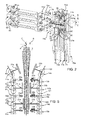
- One preferred, non-limiting embodiments of the present invention will be described by way of example with reference to the accompanying drawings, in which:
-
Figure 1 is a frontal view of a packaging unit for forming a plurality of sealed packages comprising a pair of forming assemblies according to the present invention; -
Figure 2 shows, in an enlarged view, first components of the packaging unit ofFigure 1 , with parts removed for clarity; -
Figure 3 shows in an enlarged perspective view of further components of the packaging unit ofFigure 1 , with parts removed for clarity; -
Figure 4 is a top view of the packaging unit ofFigures 1 to 3 , with parts removed for clarity; -
Figure 5 is a schematic view of different operative position of the packaging unit ofFigures 1 to 4 , with parts removed for clarity; -
Figure 6 is an enlarged perspective view of the forming assembly ofFigures 1 to 5 ; and -
Figure 7 is a perspective view of the packaging unit ofFigures 1 to 6 . With reference toFigures 1 to 7 ,number 1 indicates as a whole a packaging unit for producingsealed packs 3 of a pourable food product, such as pasteurized milk or fruit juice, from atube 2 of sheet packaging material. - The packaging material has a multilayer structure (not shown), and comprises a layer of fibrous material, normally paper, covered on both sides with respective layers of heat-seal plastic material, e.g. polyethylene.
- In the case of aseptic packages for long-storage products, such as UHT milk, the packaging material also comprises a layer of gas- and light-barrier material, e.g. aluminium foil or ethylene vinyl alcohol (EVOH) film, which is superimposed on a layer of heat-seal plastic material, and is in turn covered with another layer of heat-seal plastic material forming the inner face of the package eventually contacting the food product.
-
Tube 2 is formed in known manner by longitudinally folding and sealing a web (not shown) of heat-seal sheet material, is filled by a pipe (not shown) with the sterilized or sterile-processed food product for packaging, and is fed, in known manner not shown, along a vertical path having an axis A. - Axis A is vertical in the embodiment shown.
- It is also possible to identify:
- a direction B, which is orthogonal to axis A and horizontal in the embodiment shown; and
- a direction C, which is orthogonal to both axis A and direction B and is horizontal in the embodiment shown.
- In greater detail,
unit 1 comprises: - a pair of forming
assemblies tube 2, so as to form a number ofpillow packs 3 separated from one another; and - an
outlet conveyor 11, which is arranged below formingassembly packs 3 discharged by formingassembly 10b. - Forming
assemblies tube 2 to heat seal it at equally spaced cross sections and form a number of pillow packs 3 (Figure 1 ) connected totube 2 by transversal sealing bands crosswise to axis A. - Furthermore, forming
assemblies tube 2 to cutpillow packs 3 along respective sealing bands, so as to separatepillow pack 3 from one another. -
Outlet conveyor 11 conveyspacks 3 towards a not-shown folding unit, in whichpacks 3 are folded into corresponding not-shown packages. - Forming
assembly 10a substantially comprises: - a
frame 12a, which defines a plurality, two in the embodiment shown, oftracks 13a spaced along direction C with respect to one another; and - a plurality of groups of
carriages 14a', 15a, 14a consecutive and immediately adjacent to one another. - Forming
assembly 10b substantially comprises: - a
frame 12b, which defines a plurality, two in the embodiment shown, oftracks 13b spaced along direction C with respect to one another; and - a plurality of groups of
carriages 14b', 15b, 14b consecutive and immediately adjacent to one another. - Each
frame - two oval
planar end surfaces - a curved
continuous surface surfaces - Furthermore, each
track Figure 3 ) : - a
rectilinear portion tube 2; - a
rectilinear portion respective portion - a pair of
curved portions portions - Each
carriage assembly 10a is associated to acorresponding carriage assembly 10b. - In the very same way, each
carriage 15a of formingassembly 10a is associated to acorresponding carriage 15b. - Each pair of
corresponding carriages subsequent carriages relative pack 3. - In the following of the present description, only one group of corresponding
carriages 14a', 15b, 14a and the respective group of correspondingcarriages 14b', 15b, 15a will be described, being all thecarriages 14a', 14b'; 15a, 15b; 14a, 14b identical to one another. - Each
carriage 14a', 14a andcorresponding carriage 14b', 14b comprises respective half-shells 21a', 21a; 21b', 21b. - In detail, half-
shell Figures 2 ,4 and6 ): - a
main wall 28; and - a pair of
lateral flaps 29, which project fromwall 28 towards axis A from respective opposite edges ofwall 28 and are hinged to respective opposite edges ofwall 28 about respective axes. -
Carriage 15b comprises a sealingelement 22b and anextractable cutting element 23b. -
Corresponding carriage 15a comprises acounter-sealing element 22a and a not-shown seat, which is adapted to receive cuttingelement 23b, when the latter is extracted. - In the embodiment shown, sealing
elements 22b are heating elements.Counter-sealing elements 22a are made of elastomeric material, which provides the necessary mechanical support to griptube 2 to the required pressure. -
Carriages 14a', 14b'; 14a, 14b andcarriages respective tracks - In this way, half-
shells 21a'; 21a andcounter-sealing elements 22a of formingassembly 10a are movable independently of one another. - Half-
shells 21b'; 21b and sealingelements 22b are movable independently of one another. - With particular reference to
Figures 1 and5 , half-shells 21a', 21b'; 21a, 21b,counter-sealing elements 22a and sealingelements 22b are driven byrespective carriages 14a' 14b'; 14a, 14b; 15a, 15b along a cyclic endless path P, Q. - In particular,
carriage 14a', 14b' is arranged upstream ofcarriage carriage carriage carriages 14a', 14b'; 15a, 15b; 14a, 14b. - Path P, Q comprises, proceeding along the advancing direction of
carriages 14a', 14a; 14b', 14b; 15a, 15b (shown inFigure 1 ): - an operative branch P1, Q1, along which half-
shells 21a', 21b'; 21a, 21b,counter-sealing elements 22a and sealingelements 22b downwardly move parallel to axis A and are arranged on respective opposite sides oftube 2; and - a return branch P2, Q2, along which half-
shells 21a', 21b'; 21a, 21b,counter-sealing elements 22a and sealingelements 22b subsequently move away from axis A, upwardly move parallel to axis A on the opposite side oftube 2, and moves back towards axis A. - In greater detail, half-
shells 21a', 21b'; 21a, 21b,counter-sealing elements 22a and sealingelements 22b are driven along operative branch P1, Q1, asrespective carriages 14a', 14b', 14a, 14b; 15a, 15b move along respectiverectilinear portion relative tracks -
Counter-sealing elements 22a and sealingelements 22b are driven along return branch P2, Q2, asrespective carriages rectilinear portion curved portions relative tracks - When they are driven by
respective carriages 14a', 14a, 14b'; 14b along respective operative branch P1, Q1 of path P, Q, half-shell 21a', 21b' are arranged abovecounter-sealing element 22a and sealingelement 22b and above respective half-shell - Furthermore,
counter-sealing element 22a and sealingelement 22b are arranged above respective half-shell - When they are driven by
respective carriages 14a', 14b'; 14a, 14b along respective operative branch P1, Q1 of path P, Q, half-shells 21a', 21b'; 21a, 21b,counter-sealing elements 22a and sealingelements 22b are cyclically moved back and forth parallel to direction B (Figure 5 ) and between: - respective closed positions, in which they cooperate with
tube 2 during the formation ofpacks 3 and with formedpacks 3 after the formation thereof; and - respective open positions, in which they are detached from
tube 2. - In other words, the movement of half-
shells 21a', 21b'; 21a, 21b, andcounter-sealing element 22a and sealingelement 22b along direction B between the respective open positions and closed positions is superimposed to the movement along operative branch P1, Q1. - When half-
shells 21a', 21b'; 21a, 21b are both in the respective closed position, they define a substantially parallelepiped cavity (Figures 1 ,4 and5 ) and accordingly control the volume ofrelative pack 3 in formation. - In particular, when half-
shells 21a', 21b'; 21a, 21b are in respective closed positions,respective walls 28 are located on opposite sides of axis A, are parallel to each other, and cooperate withtube 2. In the closed position, flaps 29 of one half-shell 21a', 21b'; 21a, 21b cooperate withtube 2 to completely control the volume ofpack 3 in formation, face flaps 29 of the other half-shells 21a', 21b'; 21a, 21b and are substantially orthogonal torespective wall 28. - On the contrary, when half-
shells 21a', 21b'; 21a, 21b are in respective open positions,walls 28 are detached fromtube 2 andwalls 29 diverge fromrelative walls 28. - When
counter-sealing element 22a and sealingelement 22b are in the respective closed position, they heat-seal tube, so as form the transversal sealing band ofpack 3. - At the same time, cutting
element 23b is extracted, so as to separate the formedpack 3 from one another. - Along operative branches P1, Q1 of path P, Q:
- at first, half-
shells 21a', 21b' reach the respective closed positions; - then, half-
shells - finally,
counter-sealing element 22a and sealingelement 22b reach the respective closed position. - Furthermore, half-
shells 21a', 21b'; 21a, 21b remain in the respective closed position for a certain length parallel to axis A before correspondingcounter-sealing elements 22b and sealingelements 22b reach the respective closed positions. - With particular reference to
Figures 1 and5 , each operative branches P1, Q1 of path P, Q comprises, proceeding according to the advancing direction ofcarriages 14a', 14b'; 15a, 15b; 14a, 15a: - a respective
initial portion shells 21a', 21b'; 21a, 21b andcounter-sealing element 22a and sealingelement 22b are in respective open positions; - a
respective portion shell shells 21a', 21b' andcounter-sealing element 22a and sealingelement 22b remain in respective open positions; - a
respective portion shells shells 21a', 21b' are in respective closed position, andcounter-sealing element 22a and sealingelement 22b are still in respective open positions; - a
respective portion shells shells 21a', 21b' and sealingelement 22b andcounter-sealing element 22a are in respective closed positions; and - a
respective end portion shell 21a is in the respective open position while half-shell 21b is in the respective closed position andcounter-sealing element 22a and sealingelement 22b are in respective open positions. - Along
portions portions tube 2 is constrained by half-shells counter-sealing element 22a and sealingelement 22b are still in respective open positions. Accordingly, half-shells 21a', 21b' can be controlled to move along relative portion P1, Q1 towards half-shell pack 3 before the latter is sealed bycounter-sealing element 22a and sealingelement 22b. - Along
portions element 22b andcounter-sealing element 22a reach the respective closed positions, in which they heatseal tube 2 and form transversal sealing band ofpack 3. In the meanwhile, half-shells 21a', 21b'; 21a, 21b cooperate withrespective pack 3 in formation, so as to control the volume of thatrespective pack 3 and cuttingelement 23b is extracted to cut formedpack 3 along the transversal sealing band. - Furthermore, return branch P2 comprises, proceeding according to the advancing direction of
carriages portion 35a, which is immediately adjacent toportion 34a and along which half-shell 21a', 21a andcounter-sealing element 22a are in respective open positions. - Advantageously, half-
shell 21b is in the closed position along aportion 35b of return branch Q2, so as to grippacks 3 and conveypacks 3 in a staggered position with respect to axis A, and moves in the open position at an end 36 ofportion 35b opposite toportion 34b of operative branch Q1, so as to discharge formedpacks 3 onconveyor 11 in a staggered position with respect to axis A. -
Portion 35b is superimposed tooutlet conveyor 11, proceeding parallel to axis A. -
Portion 35b is, atend 36b, tangential to direction B and toconveyor 11, so as to smoothly release formedpack 3 onconveyor 11 tangentially to direction B andsame conveyor 11. -
Carriage 14a', 14b'; 14a, 14b substantially comprises (Figures 2 ,4 and6 ): - a
motor element 40, which extends parallel to direction C; - an
arm 41, which protrudes laterally on one side ofelement 40 and is firmly fixed toelement 40; - a
plate 42 which is movable along direction B with respect toarm 41 alongguides 43; and - a
plate 44 which is movable with respect to plate 42 parallel to direction B and along guides (not shown). -
Motor element 40 comprises a bar, which is provided at opposite axial ends thereof, with a pair ofwheels 39, which roll inside relative endless slots defined byrelative tracks - In the embodiment shown,
wheels 39 rotate about relative axes thereof parallel to direction C. -
Motor element 40 is, in the embodiment shown, magnetically coupled with magnetic field sources 55 (Figures 3 and6 ) which are carried in fixed position byrespective surfaces carriage 14a', 14b'; 14a, 14b is self-movable alongtracks -
Plate 42 is fixed, on one side thereof, to wall 28 of half-shell 21a', 21b'; 21a, 21b and comprises, on the opposite side, a pair of rollers 46 (Figure 4 ). -
Plate 44 comprises, on the side ofrollers 46, aroller 47 and is fixed, on the side of half-shell 21a', 21b'; 21a, 21b, to a cross-bar 48. -
Roller 47 is interposed betweenrollers 46 along direction C. -
Rollers 46 androller 47 roll about relative axes thereof parallel to direction C. - Cross-bar 48 is parallel to
arm 41 and defines a pair of opposite slots 49 (Figure 4 ) inclined with respect toarm 41. -
Slots 49 are slidably engaged byrelative rollers 50 connected torespective flaps 29 of half-shells 21a', 21b'; 21a, 21b. -
Carriage Figures 2 and6 ): - a
motor element 60, which extends parallel to direction C; - an
arm 61, which protrudes laterally on one side ofelement 60 and is firmly fixed toelement 60; - a
plate 62, which is movable along direction B with respect toarm 61 alongguides 63 and supportsrelative sealing element 22b orcounter-sealing element 22a on the side of axis A and, therefore, oftube 2. -
Motor element 60 comprises a bar, which is provided at opposite axial ends thereof, with a pair ofwheels 64 which roll inside relative endless slots defined byrelative tracks - In the embodiment shown,
wheels 64 rotate about relative axes thereof parallel to direction C. -
Motor element 60 is, in the embodiment shown, magnetically coupled with magnetic field sources 55 (Figures 3 and6 ) which are carried in fixed position byrespective surfaces carriage tracks -
Plate 62 is fixed, on one side thereof, to sealingelement 22b orcounter-sealing element 22a and comprises, on the opposite side, a pair ofrollers 65. -
Rollers 46 androller 47 are interposed betweenrollers 65 along direction C. - Each forming
assembly Figures 2 to 4 ) arelative cam assembly end surface 16a with respect to endsurface 16b. - Each
cam assembly - a pair of
cam surfaces rollers 46 ofcarriages 14a', 14b'; 14a, 14b travelling along operative branches P1, Q1 of path P, Q; - a
cam surface rollers 47 ofcarriages 14a', 14b'; 14a, 14b travelling along operative branches P1, Q1 of path P, Q; and - a pair of cam surfaces 73 which are in rolling contact with
rollers 65 ofcarriages - Cam surfaces 73 extend in correspondence of operative branches P1, Q1 of path P, Q.
- Cam surfaces 71a, 71b and
cam surfaces initial portion 35b of return branch Q2 (Figure 6 ). -
Cam surface cam surfaces - Cam surfaces 71a, 71b and
cam surfaces - Cam surfaces 71a, 72a and
cam surfaces shells 21a', 21b'; 21a, 21b: - remain in respective open position along
respective portions - are arranged in respective closed positions along
respective portions - Furthermore,
cam surfaces shell 21a', 21a is arranged in the open position alongportion 34a of operative branches P1. - Cam surfaces 71b, 72b comprise, in particular, (
Figures 3 and6 ): - respective
main portions 75, which have a length parallel to axis A and are shaped to keep half-shell 21b', 21b in the closed positions alongportion 34b of operative branch Q1 and alonginitial portion 35b of return branch Q2; and -
respective end portions 76, which extend as of respectivemain portions 75 at increasing distances from axis A, proceeding according to the advancing direction ofcarriage shell 21b in the closed positions alonginitial portion 35b of return branch Q2 and to displace half-shell 21b in the open position atend 36b ofinitial portion 35b. -
Conveyor 11 comprises (Figure 7 ): - an
inlet station 85, which receives, under gravity action, packs 3 which are discharged by half-shells 21b atend 36b; - an outlet station (not-shown), which is opposite to station 85 and feeds the not-shown folding unit; and
- an
operative branch 87, which extends parallel to direction B frominlet station 85 to outlet station and is tangential toportion 35b atend 36b. - In the embodiment shown,
conveyor 11 is a belt conveyor. - In use,
tube 2 is advanced along axis A andcarriages 14a', 15a, 14a, and 14b', 15b, 14b advance independently of one another alongtracks Figure 1 . - In particular,
carriages 14a', 15a, 14a and 14b', 15b, 14b are self-movable ontracks 13a; 13b along respective paths P, Q. - The operation of
unit 1 is described hereinafter with reference to only one group ofcarriages 14a', 14b, 14a and only one group of correspondingcarriages 15a', 15b, 15a and to the only onepack 3 formed by using half-shells 21a', 21b', sealingelement 22b andcounter-sealing element 22a and half-shell respective carriages 14a', 14b', 15a, 15b; 14a, 14b. -
Carriages 14a', 14b'; 15a, 15b; 14a, 14b move at first along respective return branches P2, Q2 of respective path P, Q and then along respective operative branches P1, Q1 of respective paths P, Q. - As
carriages 14a', 14b'; 14a, 14b move along operative branches P1, Q1, respective half-shells 21a', 21b'; 21a, 21b move back and forth parallel to direction B and between the respective open positions and the respective closed positions. - In the very same way, as
carriages counter-sealing element 22a and sealingelement 22b move back and forth parallel to direction B and between the respective open positions and the respective closed positions. - In particular, along operative branches P1, Q1, half-
shell 21a', 21b' are arranged abovecounter-sealing element 21a and sealingelement 21b, which are, in turn, arranged above half-shell - The operation of
unit 1 is now described starting from a position, in which , alongportions shells 21a', 21b'; 21a, 21b,counter-sealing element 22a and sealingelement 22b are in respective open positions alongrespective portions - In this situation, half-
shells 21a', 21b', 21a, 21b,counter-sealing element 22a andcounter-sealing element 22b are detached fromtube 2. Furthermore, flaps 29 of half-shells wall 28, proceeding from the latter towards axis A. - Along
portions shells shells 21a', 21b',counter-sealing element 22a and sealingelement 22b remain in respective open positions. - Along
portions shells shells 21a', 21b' reach the respective closed position. In the meanwhile,counter-sealing element 22a and sealingelement 22b remain in the respective open positions. - Furthermore, along
portion tube 2 is constrained by half-shells shells 21a', 21b' - arranged in a top position - towards half-shells element 22b andcounter-sealing element 22a still in the respective open positions. - Accordingly, the action of half-
shells 21a', 21b is effective in completing the folding ofpacks 3. - Along
portions counter-sealing element 22a and sealingelement 22b are in the closed position, with half-shells 21a', 21b'; 21a, 21b still kept in the respective closed positions. - Accordingly, flaps 29 of opposite half-
shells 21a', 21b'; 21a, 21b face one another and define a parallelepiped cavity, which houses a portion oftube 2 destined to formpack 3. -
Sealing element 22b is activated to heat-seal tube 2 in the desired sealing area thereof, so as to form transversal sealing band ofpack 3 in the desired area with respect to the images repeatedly printed ontube 2. - During the sealing of the transversal sealing band, half-
shells 21a', 21b'; 21a, 21b control the volume ofpack 3. - Furthermore, cutting
element 23b is extracted up to engage the seat, so as to cut the transversal sealing band ofpack 3, so as to separate the latter from the remaining part oftube 2. - Along
portions counter-sealing element 22a and sealingelement 22b are in the respective open positions, half-shell 21a', 21a is in the open position, while half-shell 21b', 21b remains in the closed position. - As a result, formed, sealed and cut
pack 3 is gripped and held by half-shell 21b. - The further movement of
carriage 14b alongtrack 13b causes the corresponding movement of half-shell 21b alonginitial portion 35b of path Q1. - As half-
shell 21b reachesend 36b ofportion 35b of Q1, it is moved from the closed position to the open position, thus releasingpack 3 tangentially to direction B oninlet station 85 ofconveyor 11, which feedspack 3 to the not-shown folding unit. - The movement of half-
shells 21a', 21b'; 21a, 21b between the respective open positions and closed positions is determined by the rolling ofrollers carriages respective cam surfaces - This movement is described starting from the open positions of half-
shells 21a', 21b'; 21a, 21b, whencarriages respective portions - Due to the rolling movement of
rollers 46 oncam surfaces plates 42 move towards axis A andtube 2 alongrespective guides 43 with respect torespective motor elements 40 andrespective arms 41. - As a result,
plates 42 move parallel to direction B, thus causing the displacement of the relative whole half-shells 21a', 21b'; 21a, 21b towardstube 2 up to a position in whichwalls 28contact tube 2. - Then, the rolling movement of
rollers 47 onrelative cam surfaces relative plates 44 with respect to correspondingplates 42 parallel to direction B, towards axis A and on not-shown guides. - As a result,
slots 49 move towards axis A, causing the rotation ofrollers 50 and offlaps 29 from a position in which they diverge with respect to wall 28 proceeding towardstube 2 up to reach a position, in which they are orthogonal to wall 28 andgrip tube 2 or sealedpack 3. - At this stage, the half-
shells 21a', 21b'; 21a, 21b are arranged in the respective closed positions. - The movement of half-
shells 21a', 21b'; 21a, 21b from the respective closed position to the respective open positions is determined by the fact that at firstrespective plate 44 move away fromrespective plates 42 and slide on respective not-shown guides parallel to direction B, In this way, flaps 29 rotate back up to a position in which they diverge fromrespective walls 28, proceeding fromwalls 28 towards axis A. - The movement of half-
shells 21a', 21b'; 21a, 21b is completed, thanks to the fact thatplates 42 moves away fromtube 2 and slide parallel to direction B along relative guides 43 with respect torelative arm 41. - These movements of half-
shells 21a', 21b'; 21a, 21b towards respective closed positions are eased by not-shown springs which act onplate 42 andplate 44. - In this way, the whole half-
shells 21a', 21b'; 21a, 21b are moved away fromtube 2, up to reach again the respective open positions. - The movement of
counter-sealing element 22a and sealingelement 22b between the respective open positions and closed positions is determined by the rolling ofrollers 65 ofcarriages - That movement is described starting from the open positions of
counter-sealing element 22a and sealingelement 22b, whenrespective carriages - Due to the rolling of
rollers 65 onto respective cam surfaces 73,plates 62 move alongrespective guides 63 parallel to direction B and towardstube 2 with respect toarm 61 andmotor element 60, up tocontact tube 2 in the desired position for forming the transversal sealing band ofpack 3. - At this stage, sealing
element 22b andcounter-sealing element 22a are arranged in the respective closed positions. - The movement of sealing
element 22b andcounter-sealing element 22a from the respective closed position to the respective open positions is determined by the fact thatplates 62 move back alongrespective guide 63 parallel to direction B and on the opposite side oftube 2. - This movement is eased by not-shown springs, which act on
plates 62. - The advantages of forming
assembly - The half-
shells 21b are kept in respective closed position alongportion 34b of portion Q2 of path Q diverging from axis A, and are displaced in respective open position atend 36b, so as to dischargedpacks 3 onconveyor 11. - In this way, it is ensured that, even in presence of connecting bridges between two consecutive cut and sealed
packs 3, the movement of half-shell 21b detaches the consecutive sealedpacks 3 and thus properly convey separatedpacks 2 toconveyor 11. - In this way, it is achieved a higher degree of precision and repeatibility in the detachment and feeding of
packs 3 toconveyor 11 with respect to the known solutions, which substantially rely on the gravity action. - Clearly, changes may be made to forming
assembly - In particular, forming
assemblies EP-B-0887265 instead ofcarriages
Claims (15)
- A forming assembly (10b) for forming a plurality of sealed packs (3) starting from a tube (2) of packaging material, comprising first conveying means (14b, 15b, 14b') movable along an endless first path (Q);
said first path (Q) comprising, in turn, proceeding according to the advancing direction of said first conveying means (14b, 15b, 14b'):- a first operative branch (Q1), which has a main elongation direction parallel to an advancing direction (A) of said tube (2); and- a first return branch (Q2) comprising, in turn, an initial portion (35b) which is arranged immediately downstream of said operative branch (Q1) and extends transversally to said advancing direction (A);said first conveying means (14b, 15b, 14b') comprising, in turn:- one of a sealing element (22b) or a counter-sealing element (22a) adapted to seal said pack (3) along said first operative branch (Q1); and- a first half-shell (21b, 21b'), which is movable along said operative branch (Q1) between:a first rest position, in which it is detached, in use, from said tube (2) or said formed pack (3); and
a first operative position, in which it grips said tube (2) or said formed pack (3);
said first half-shell (21b, 21b') being arranged in said first operative position along a first portion (34b) of said first operative branch (Q1);
characterized in that said first half-shell (21b, 21b') is kept, in use, in said first operative position along said initial portion (35b), so as to grip and convey said pack (3) in a staggered position with respect to said advancing direction (A); and moves, in use, from said first operative position to said rest position at an end (36b) of said initial portion (35b) opposite to said first portion (34b), so as to discharge said pack (3) in a staggered position with respect to said advancing direction (A). - The forming assembly of claim 1, characterized in that said initial portion (35b) is arranged immediately downstream and adjacent to said first portion (34b), proceeding according to the advancing direction of said first conveying means (14b, 15b, 14b') along said path (Q).
- The forming assembly of claim 2, characterized in that said first operative branch (Q1) further comprises:- a second portion (32b), along which said first half-shell (21b) is in said first operative position;- a third portion (33b), along which said first half-shell (21b) is in said first operative position;
said third portion (33b) being interposed between said second portion (32b) and said first portion (34b), proceeding according to the advancing direction of said first conveying means (14b, 15b, 14b') along said first path (Q). - The forming assembly of claim 3, characterized in that said one of a sealing element (22b) or a counter-sealing element (22a) is movable between:- a second operative position, in which it contacts, in use, said tube (2) so as to seal said pack (3); and- a second rest position, in which in it is, in use, detached from said tube (2) or said formed pack (3) ;
said one of a sealing element (22b) or a counter-sealing element (22a) being arranged, in use, in said second rest position along said second portion (32b) and said first portion (34b);
said one of a sealing element (22b) or a counter-sealing element (22a) being arranged, in use, in said second operative position along said third portion (33b). - The forming assembly of any one of the foregoing claims, characterized in that said first half-shell (21b) comprises, in turn,:- a main wall (28); and- a pair of flaps (29) hinged to said main wall (28) ;
said forming assembly (10b) comprising a frame (12b);
said first conveying means (14b, 15b, 14b') comprising a first body (40), which is movable with respect to said frame (12b) along said first path (Q);- a second body (42), which protrudes from said first body (40), is staggered from said frame (12b), carries said wall (28) of said first half-shell (21b, 21b'), and comprises a second cam follower (46); and- a third body (44), which is movable with respect to said second body (42) transversally to said advancing direction (A), is operatively connected to said flaps (29), and comprises at least one third cam follower (47);
said forming assembly (10b) further comprising:- a second cam surface (71b), which cooperates with said second cam follower (46), so as to move said wall (28) towards or away from said tube (2); and- a third cam surface (72b), which cooperates with said third cam follower (47), so as to move said flaps (29) with respect to said wall (28). - The forming assembly of claim 5, characterized in that said second cam surface (71b) and said third cam surface (72b) comprise:- a main portion (75), which is elongated parallel to said advancing direction (A) and which is configured to keep said first half-shell (21b, 21b') in respective said first operative position along said second portion (32b), third portion (33b) and said first portion (34b) of said first operative branch (Q1); and- a curved end portion (76), which extends as of said main portion (75) at increasing distances from said advancing direction (A), proceeding according to the advancing direction of said first conveying means (14b, 15b, 14b'), and which is configured to keep said first half-shell (21b) in respective said first operative position along said initial portion (35b) of said return branch (Q2) and to displace said first half-shell (21b, 21b') in said first rest position at said end (36b) of said initial portion (35b).
- The forming assembly of any one of the foregoing claims, characterized by comprising a discharge conveyor (11), which is arranged at said end (36b), is tangential to said initial portion (35b) at said end (36b), and is adapted to directly receive said formed packs (3) discharged from said first half-shell (21b).
- The forming assembly of claim 6 or 7, characterized in that said frame (12b) defines at least one track (13b);
said first body (40) contacting and being self-movable on said track (13b) along said first path (Q);
said second body (42) and third body (44) being driven by said first body (40) along said first path (Q). - A packaging unit (1) for producing a plurality of sealed packs (3) starting from a tube (2) of packaging material, comprising:- a forming assembly (10b) according to any one of the foregoing claims; and- an additional forming assembly (10a), which cooperates with said forming assembly (10b) to seal said packs (3);
said additional forming assembly (10a) comprising additional conveying means (14a, 15a, 14a') movable along an additional endless path (P);
said additional path (P) comprising, in turn, proceeding according to the advancing direction of said first conveying means (14b, 15b, 14b'):- an additional operative branch (PI), which has a main elongation direction parallel to said advancing direction (A); and- an additional return branch (P2) comprising, in turn, an initial portion (35a) which is arranged immediately downstream of said additional operative branch (P1) and extends transversally to said advancing direction (A);
said additional conveying means (14a, 15a, 14a') comprising, in turn:- the other one of a sealing element (22b) or a counter-sealing element (22a), which is adapted to cooperate with said one of said a sealing element (22b) or a counter-sealing element (22a) to seal said pack (3) along said additional operative branch (P1); and- a second half-shell (21a, 21a'), which is movable along said additional operative branch (P1) between:an additional first rest position, in which said it is detached, in use, from said tube (2) or said formed pack (3); andan additional first operative position, in which it grips said tube (2) or said formed pack (3) and cooperate with said first half-shell (21b) in controlling the shape of said pack (3) during the formation thereof;said second half-shell (21a, 21a') being arranged in said additional first operative position along an additional second portion (32a) and an additional third portion (33a) of said additional operative branch (P1); said additional second portion (32a) and additional third portion (33b) of said additional operative branch (P1) facing and being opposite respectively to said second portion (32b) and third portion (33b) of said operative branch (Q1);said second half-shell (21a, 21a') being arranged in said additional first rest position along an additional first portion (34a) of said additional operative branch (P1); said additional first portion (34a) of said additional operative branch (P1) facing and being opposite to said first portion (34b) of said operative branch (Q1);said first portion (34a) being adjacent and upstream of said initial portion (35a), proceeding according to the advancing direction of said first conveying means (14a; 14b). - A method for forming a plurality of sealed packs (3) starting from a tube (2) of packaging material, comprising the steps of:i) advancing said tube (2) along an advancing direction (A); andii) moving first conveying means (15a, 15b, 15a') along an endless first path (Q), which is formed by:- a first operative branch (Q1), which has a main elongation direction parallel to said advancing direction (A); and- a first return branch (Q2) comprising, in turn, an initial portion (35b) which is arranged immediately downstream of said first operative branch (Q1) and extends transversally to said advancing direction (A);
said first conveying means (15a, 15b, 15a') comprising, in turn:- one of a sealing element (22b) or a counter-sealing element (22a) adapted to seal said pack (3) along said operative branch (Q1); and- a first half-shell (21b);
said step ii) comprising the steps of:iii) moving said first half-shell (21b, 21b') along said first operative branch (Q1) between:- a first rest position, in which it is detached from said tube (2) or said formed pack (3); and- a first operative position, in which it grips said tube (2) or said formed pack (3); andiv) arranging said first half-shell (21b, 21b') in said first operative position along a first portion (34b) of said first operative branch (Q1);
characterized by comprising the steps of:v) keeping said first half-shell (21b, 21b') in said first operative position along an initial portion (35b) of said first return branch (Q2), so as to grip and convey said pack (3) in a staggered position with respect to said advancing direction (A); andvi) moving said first half-shell (21b, 21b') from said first operative position to said rest position at an end (36b) of said initial portion (35b), so as to discharge said pack (3) in a staggered position with respect to said advancing direction (A). - The method of claim 10, characterized in that said initial portion (35b) is arranged immediately downstream and adjacent to said first portion (34b), proceeding according to the advancing direction of said first conveying means (14b, 15b, 14b') along said first path (Q).
- The method of claim 10 or 11, characterized in that said step ii) comprises the steps of:vii) arranging said first half-shell (21b) in said first operative position along a second portion (32b) of said operative branch (Q1); andviii) arranging said first half-shell (21b, 21b') in said first operative position along a third portion (33b) of said first operative branch (Q1);
said third portion (33b) being interposed between said second portion (32b) and said first portion (34b), proceeding according to the advancing direction of said first conveying means (15a, 15b, 15a') along said first path (Q). - The method of claim 12, characterized by comprising the steps of:ix) moving said one of said one of a sealing element (22b) or a counter-sealing element (22a) between:- a second operative position, in which it contacts said tube (2) so as to seal said pack (3); and- a second rest position, in which it is detached from said tube (2) or said formed pack (3);
said step ix) comprising the steps:x) arranging said one of a sealing element (22b) or a counter-sealing element (22a) in said second rest position along said second portion (32b) and said first portion (34b); andxi) arranging said one of a sealing element (22b) or a counter-sealing element (22a) in said second operative position along said third portion (33b). - The method of any one of claims 10 to 13, characterized by comprising a step of:xii) directly discharging said formed pack (3) from said first half-shell (21b, 21b') on a discharge conveyor (11), which is arranged at said end (36b) and is tangential to said initial portion (35b) at said end (36b).
- The method of any one of claims 10 to 14, characterized by comprising the steps of:xiii) moving additional conveying means (14a, 15a, 14a') carried by an additional forming assembly (10a) along an endless additional path (P), which comprises, proceeding according to the advancing direction of said first conveying means (14a, 15a, 14a'), in turn:- an additional operative branch (PI), which has a main elongation direction parallel to said advancing direction (A); and- an additional return branch (P2) comprising, in turn, an initial portion (35a) which is arranged immediately downstream of said additional operative branch (P1) and extends transversally to said advancing direction (A);
said additional conveying means (14a, 15a, 14a') comprising, in turn:- the other one of a sealing element (22b) or a counter-sealing element (22a); and- a second half-shell (21a, 21a');
said step xiii) comprising the steps of:xiv) moving said second half-shell (21a) along said additional operative branch (P1) between:- an additional first rest position, in which it is detached from said tube (2) or said formed pack (3); and- an additional first operative position, in which it grips said tube (2) or said formed pack (3);
characterized by comprising the step of:xv) arranging said second half-shell (21a) in said additional first rest position along an additional first portion (34a) of said additional operative branch (P1);
said additional first portion (34a) of said additional operative branch (P1) facing and being opposite to said first portion (34b) of said operative branch (Q1).
Priority Applications (7)
| Application Number | Priority Date | Filing Date | Title |
|---|---|---|---|
| EP15153730.5A EP3053835B1 (en) | 2015-02-04 | 2015-02-04 | Forming assembly and method for forming a plurality of sealed packs for pourable food products starting from a tube of packaging material |
| CN201680007508.1A CN107207109B (en) | 2015-02-04 | 2016-02-02 | The multiple seal-packed formation components and method of pourable food are initially formed from packaging material tube |
| BR112017016594A BR112017016594A2 (en) | 2015-02-04 | 2016-02-02 | forming assembly, packaging unit, and method for forming a plurality of sealed packages. |
| KR1020177019534A KR101854097B1 (en) | 2015-02-04 | 2016-02-02 | Forming assembly and method for forming a plurality of sealed packs for pourable food products starting from a tube of packaging material |
| US15/542,796 US10195790B2 (en) | 2015-02-04 | 2016-02-02 | Forming assembly and method for forming a plurality of sealed packs for pourable food products starting from a tube of packaging material |
| PCT/EP2016/052113 WO2016124560A1 (en) | 2015-02-04 | 2016-02-02 | Forming assembly and method for forming a plurality of sealed packs for pourable food products starting from a tube of packaging material |
| JP2017540099A JP6353170B2 (en) | 2015-02-04 | 2016-02-02 | Molding assembly and method for molding multiple seal packs for flowable food starting from a tube of packaging material |
Applications Claiming Priority (1)
| Application Number | Priority Date | Filing Date | Title |
|---|---|---|---|
| EP15153730.5A EP3053835B1 (en) | 2015-02-04 | 2015-02-04 | Forming assembly and method for forming a plurality of sealed packs for pourable food products starting from a tube of packaging material |
Publications (2)
| Publication Number | Publication Date |
|---|---|
| EP3053835A1 true EP3053835A1 (en) | 2016-08-10 |
| EP3053835B1 EP3053835B1 (en) | 2019-04-03 |
Family
ID=52462165
Family Applications (1)
| Application Number | Title | Priority Date | Filing Date |
|---|---|---|---|
| EP15153730.5A Active EP3053835B1 (en) | 2015-02-04 | 2015-02-04 | Forming assembly and method for forming a plurality of sealed packs for pourable food products starting from a tube of packaging material |
Country Status (7)
| Country | Link |
|---|---|
| US (1) | US10195790B2 (en) |
| EP (1) | EP3053835B1 (en) |
| JP (1) | JP6353170B2 (en) |
| KR (1) | KR101854097B1 (en) |
| CN (1) | CN107207109B (en) |
| BR (1) | BR112017016594A2 (en) |
| WO (1) | WO2016124560A1 (en) |
Cited By (5)
| Publication number | Priority date | Publication date | Assignee | Title |
|---|---|---|---|---|
| EP3476751A1 (en) | 2017-10-31 | 2019-05-01 | Tetra Laval Holdings & Finance S.A. | A packaging assembly for forming and sealing a plurality of packs containing a pourable food product |
| CN110171673A (en) * | 2018-02-19 | 2019-08-27 | 利乐拉瓦尔集团及财务有限公司 | Packing device, conveying equipment and the cart component for conveying equipment |
| EP3708507A1 (en) * | 2019-03-14 | 2020-09-16 | Tetra Laval Holdings & Finance S.A. | Method for preparing a packaging machine |
| EP3760548A1 (en) * | 2019-07-01 | 2021-01-06 | Tetra Laval Holdings & Finance S.A. | A packaging assembly for forming and sealing a plurality of packs containing a pourable product and a method for forming and sealing a plurality of packs |
| CN117602159A (en) * | 2024-01-23 | 2024-02-27 | 四川英创力电子科技股份有限公司 | Automatic circuit board feeding device and method with film coating function |
Families Citing this family (2)
| Publication number | Priority date | Publication date | Assignee | Title |
|---|---|---|---|---|
| EP3254980B1 (en) * | 2016-06-09 | 2018-12-19 | Tetra Laval Holdings & Finance S.A. | A packaging apparatus for forming sealed packages from a tube of packaging material |
| US11878828B2 (en) * | 2018-05-11 | 2024-01-23 | Tetra Laval Holdings & Finance S.A. | Outfeed device for a packaging assembly and packaging assembly comprising an outfeed device |
Citations (3)
| Publication number | Priority date | Publication date | Assignee | Title |
|---|---|---|---|---|
| US4073121A (en) * | 1975-04-28 | 1978-02-14 | The Dow Chemical Company | Form, fill and seal industrial bag machine |
| US20020014055A1 (en) * | 2000-08-01 | 2002-02-07 | Seisaku Iwasa | Vertical bag form-fill-seal packaging machine |
| EP0887265B1 (en) | 1997-06-27 | 2002-11-20 | Tetra Laval Holdings & Finance SA | Packaging unit for continuously producing sealed packages, containing pourable food products, from a tube of packaging material |
Family Cites Families (6)
| Publication number | Priority date | Publication date | Assignee | Title |
|---|---|---|---|---|
| DE1032157B (en) * | 1956-06-02 | 1958-06-12 | Rose Brothers Ltd | Method and device for packaging liquids in plastic containers |
| IT1233620B (en) | 1989-06-06 | 1992-04-07 | Italpack Srl | FILLING AND PACKAGING MACHINE |
| EP0887264B1 (en) * | 1997-06-27 | 2003-10-22 | Tetra Laval Holdings & Finance SA | Packaging unit for continuously producing sealed packages, containing pourable food products, from a tube of packaging material |
| ATE282551T1 (en) * | 1997-06-27 | 2004-12-15 | Tetra Laval Holdings & Finance | PACKAGING MACHINE FOR CONTINUOUSLY PRODUCING SEALED PACKAGINGS OF FLOWABLE FOODS FROM TUBULAR PACKAGING MATERIAL |
| EP1547230B1 (en) * | 2002-06-05 | 2017-03-22 | Jacobs Automation, Inc. | Controlled motion system |
| JP2014162536A (en) * | 2013-02-27 | 2014-09-08 | Kureha Corp | Package manufacturing apparatus |
-
2015
- 2015-02-04 EP EP15153730.5A patent/EP3053835B1/en active Active
-
2016
- 2016-02-02 CN CN201680007508.1A patent/CN107207109B/en active Active
- 2016-02-02 US US15/542,796 patent/US10195790B2/en active Active
- 2016-02-02 BR BR112017016594A patent/BR112017016594A2/en not_active Application Discontinuation
- 2016-02-02 KR KR1020177019534A patent/KR101854097B1/en not_active Expired - Fee Related
- 2016-02-02 WO PCT/EP2016/052113 patent/WO2016124560A1/en not_active Ceased
- 2016-02-02 JP JP2017540099A patent/JP6353170B2/en active Active
Patent Citations (3)
| Publication number | Priority date | Publication date | Assignee | Title |
|---|---|---|---|---|
| US4073121A (en) * | 1975-04-28 | 1978-02-14 | The Dow Chemical Company | Form, fill and seal industrial bag machine |
| EP0887265B1 (en) | 1997-06-27 | 2002-11-20 | Tetra Laval Holdings & Finance SA | Packaging unit for continuously producing sealed packages, containing pourable food products, from a tube of packaging material |
| US20020014055A1 (en) * | 2000-08-01 | 2002-02-07 | Seisaku Iwasa | Vertical bag form-fill-seal packaging machine |
Cited By (14)
| Publication number | Priority date | Publication date | Assignee | Title |
|---|---|---|---|---|
| JP2021501100A (en) * | 2017-10-31 | 2021-01-14 | テトラ ラバル ホールディングス アンド ファイナンス エス エイ | Package assembly for forming and sealing multiple packs containing injectable food products |
| CN109720617A (en) * | 2017-10-31 | 2019-05-07 | 利乐拉瓦尔集团及财务有限公司 | It is configured to define and seals the package component of multiple packets comprising pourable food |
| WO2019086307A1 (en) | 2017-10-31 | 2019-05-09 | Tetra Laval Holdings & Finance S.A. | A packaging assembly for forming and sealing a plurality of packs containing a pourable food product |
| EP3476751A1 (en) | 2017-10-31 | 2019-05-01 | Tetra Laval Holdings & Finance S.A. | A packaging assembly for forming and sealing a plurality of packs containing a pourable food product |
| CN109720617B (en) * | 2017-10-31 | 2021-11-16 | 利乐拉瓦尔集团及财务有限公司 | Package assembly configured to form and seal a plurality of packs containing pourable food products |
| US10994873B2 (en) | 2017-10-31 | 2021-05-04 | Tetra Laval Holdings & Finance S.A. | Packaging assembly for forming and sealing a plurality of packs containing a pourable food product |
| CN110171673A (en) * | 2018-02-19 | 2019-08-27 | 利乐拉瓦尔集团及财务有限公司 | Packing device, conveying equipment and the cart component for conveying equipment |
| CN110171673B (en) * | 2018-02-19 | 2021-11-16 | 利乐拉瓦尔集团及财务有限公司 | Packaging device, conveying equipment and trolley assembly for conveying equipment |
| WO2020182543A1 (en) * | 2019-03-14 | 2020-09-17 | Tetra Laval Holdings & Finance S.A. | Method for preparing a packaging machine |
| EP3708507A1 (en) * | 2019-03-14 | 2020-09-16 | Tetra Laval Holdings & Finance S.A. | Method for preparing a packaging machine |
| WO2021001144A1 (en) * | 2019-07-01 | 2021-01-07 | Tetra Laval Holdings & Finance S.A. | A packaging assembly for forming and sealing a plurality of packs containing a pourable product and a method for forming and sealing a plurality of packs |
| EP3760548A1 (en) * | 2019-07-01 | 2021-01-06 | Tetra Laval Holdings & Finance S.A. | A packaging assembly for forming and sealing a plurality of packs containing a pourable product and a method for forming and sealing a plurality of packs |
| CN117602159A (en) * | 2024-01-23 | 2024-02-27 | 四川英创力电子科技股份有限公司 | Automatic circuit board feeding device and method with film coating function |
| CN117602159B (en) * | 2024-01-23 | 2024-04-05 | 四川英创力电子科技股份有限公司 | Automatic circuit board placement device and method with laminating function |
Also Published As
| Publication number | Publication date |
|---|---|
| JP2018503569A (en) | 2018-02-08 |
| WO2016124560A1 (en) | 2016-08-11 |
| KR20170085613A (en) | 2017-07-24 |
| CN107207109A (en) | 2017-09-26 |
| BR112017016594A2 (en) | 2018-04-10 |
| CN107207109B (en) | 2019-01-01 |
| JP6353170B2 (en) | 2018-07-04 |
| US20180001574A1 (en) | 2018-01-04 |
| EP3053835B1 (en) | 2019-04-03 |
| KR101854097B1 (en) | 2018-05-02 |
| US10195790B2 (en) | 2019-02-05 |
Similar Documents
| Publication | Publication Date | Title |
|---|---|---|
| US10449728B2 (en) | Forming assembly and method for forming a plurality of sealed packs for pourable food products starting from a tube of packaging material | |
| US10195790B2 (en) | Forming assembly and method for forming a plurality of sealed packs for pourable food products starting from a tube of packaging material | |
| EP3476751B1 (en) | A packaging assembly for forming and sealing a plurality of packs containing a pourable food product | |
| EP2586716B1 (en) | Folding unit for pourable food product packaging machines | |
| EP2586719B1 (en) | Folding unit and method for producing pourable food product packages | |
| EP2586715A1 (en) | Feeding unit and method for feeding sealed packs of pourable food products | |
| KR101888723B1 (en) | Folding unit for pourable food product packaging machines | |
| EP2886473B1 (en) | Feeding unit for feeding sealed packs of pourable food products | |
| EP2586718A1 (en) | Folding unit for producing folded packages of pourable food products from relative sealed packs | |
| EP2284084A1 (en) | Folding unit for pourable food product packaging machines | |
| EP1726526B1 (en) | Folding unit for pourable food product packaging machines | |
| WO2023198615A1 (en) | Infeed conveyor for a folding apparatus, folding apparatus having an infeed conveyor and packaging machine having a folding apparatus | |
| EP3020642A1 (en) | Folding unit for producing folded packages from sealed packs | |
| WO2025031661A1 (en) | Forming unit for forming sealed packs containing a pourable product and method for forming sealed packs containing a pourable product |
Legal Events
| Date | Code | Title | Description |
|---|---|---|---|
| PUAI | Public reference made under article 153(3) epc to a published international application that has entered the european phase |
Free format text: ORIGINAL CODE: 0009012 |
|
| AK | Designated contracting states |
Kind code of ref document: A1 Designated state(s): AL AT BE BG CH CY CZ DE DK EE ES FI FR GB GR HR HU IE IS IT LI LT LU LV MC MK MT NL NO PL PT RO RS SE SI SK SM TR |
|
| AX | Request for extension of the european patent |
Extension state: BA ME |
|
| STAA | Information on the status of an ep patent application or granted ep patent |
Free format text: STATUS: REQUEST FOR EXAMINATION WAS MADE |
|
| 17P | Request for examination filed |
Effective date: 20170210 |
|
| RBV | Designated contracting states (corrected) |
Designated state(s): AL AT BE BG CH CY CZ DE DK EE ES FI FR GB GR HR HU IE IS IT LI LT LU LV MC MK MT NL NO PL PT RO RS SE SI SK SM TR |
|
| REG | Reference to a national code |
Ref country code: DE Ref legal event code: R079 Ref document number: 602015027409 Country of ref document: DE Free format text: PREVIOUS MAIN CLASS: B65B0009100000 Ipc: B65B0009120000 |
|
| GRAP | Despatch of communication of intention to grant a patent |
Free format text: ORIGINAL CODE: EPIDOSNIGR1 |
|
| STAA | Information on the status of an ep patent application or granted ep patent |
Free format text: STATUS: GRANT OF PATENT IS INTENDED |
|
| RIC1 | Information provided on ipc code assigned before grant |
Ipc: B65B 61/24 20060101ALI20181031BHEP Ipc: B29C 65/36 20060101ALN20181031BHEP Ipc: B29C 65/74 20060101ALN20181031BHEP Ipc: B29C 65/78 20060101ALN20181031BHEP Ipc: B65B 51/30 20060101ALI20181031BHEP Ipc: B29C 65/02 20060101ALN20181031BHEP Ipc: B65B 9/12 20060101AFI20181031BHEP Ipc: B29K 23/00 20060101ALN20181031BHEP Ipc: B65B 61/28 20060101ALI20181031BHEP |
|
| INTG | Intention to grant announced |
Effective date: 20181129 |
|
| RIC1 | Information provided on ipc code assigned before grant |
Ipc: B29C 65/36 20060101ALN20181116BHEP Ipc: B29C 65/02 20060101ALN20181116BHEP Ipc: B65B 9/12 20060101AFI20181116BHEP Ipc: B29C 65/78 20060101ALN20181116BHEP Ipc: B65B 51/30 20060101ALI20181116BHEP Ipc: B65B 61/24 20060101ALI20181116BHEP Ipc: B65B 61/28 20060101ALI20181116BHEP Ipc: B29C 65/74 20060101ALN20181116BHEP Ipc: B29K 23/00 20060101ALN20181116BHEP |
|
| GRAS | Grant fee paid |
Free format text: ORIGINAL CODE: EPIDOSNIGR3 |
|
| GRAA | (expected) grant |
Free format text: ORIGINAL CODE: 0009210 |
|
| STAA | Information on the status of an ep patent application or granted ep patent |
Free format text: STATUS: THE PATENT HAS BEEN GRANTED |
|
| AK | Designated contracting states |
Kind code of ref document: B1 Designated state(s): AL AT BE BG CH CY CZ DE DK EE ES FI FR GB GR HR HU IE IS IT LI LT LU LV MC MK MT NL NO PL PT RO RS SE SI SK SM TR |
|
| REG | Reference to a national code |
Ref country code: GB Ref legal event code: FG4D |
|
| REG | Reference to a national code |
Ref country code: CH Ref legal event code: EP Ref country code: AT Ref legal event code: REF Ref document number: 1115440 Country of ref document: AT Kind code of ref document: T Effective date: 20190415 |
|
| REG | Reference to a national code |
Ref country code: DE Ref legal event code: R096 Ref document number: 602015027409 Country of ref document: DE |
|
| REG | Reference to a national code |
Ref country code: IE Ref legal event code: FG4D |
|
| REG | Reference to a national code |
Ref country code: NL Ref legal event code: MP Effective date: 20190403 |
|
| REG | Reference to a national code |
Ref country code: LT Ref legal event code: MG4D |
|
| REG | Reference to a national code |
Ref country code: AT Ref legal event code: MK05 Ref document number: 1115440 Country of ref document: AT Kind code of ref document: T Effective date: 20190403 |
|
| PG25 | Lapsed in a contracting state [announced via postgrant information from national office to epo] |
Ref country code: NL Free format text: LAPSE BECAUSE OF FAILURE TO SUBMIT A TRANSLATION OF THE DESCRIPTION OR TO PAY THE FEE WITHIN THE PRESCRIBED TIME-LIMIT Effective date: 20190403 |
|
| PG25 | Lapsed in a contracting state [announced via postgrant information from national office to epo] |
Ref country code: NO Free format text: LAPSE BECAUSE OF FAILURE TO SUBMIT A TRANSLATION OF THE DESCRIPTION OR TO PAY THE FEE WITHIN THE PRESCRIBED TIME-LIMIT Effective date: 20190703 Ref country code: FI Free format text: LAPSE BECAUSE OF FAILURE TO SUBMIT A TRANSLATION OF THE DESCRIPTION OR TO PAY THE FEE WITHIN THE PRESCRIBED TIME-LIMIT Effective date: 20190403 Ref country code: HR Free format text: LAPSE BECAUSE OF FAILURE TO SUBMIT A TRANSLATION OF THE DESCRIPTION OR TO PAY THE FEE WITHIN THE PRESCRIBED TIME-LIMIT Effective date: 20190403 Ref country code: CZ Free format text: LAPSE BECAUSE OF FAILURE TO SUBMIT A TRANSLATION OF THE DESCRIPTION OR TO PAY THE FEE WITHIN THE PRESCRIBED TIME-LIMIT Effective date: 20190403 Ref country code: LT Free format text: LAPSE BECAUSE OF FAILURE TO SUBMIT A TRANSLATION OF THE DESCRIPTION OR TO PAY THE FEE WITHIN THE PRESCRIBED TIME-LIMIT Effective date: 20190403 Ref country code: PT Free format text: LAPSE BECAUSE OF FAILURE TO SUBMIT A TRANSLATION OF THE DESCRIPTION OR TO PAY THE FEE WITHIN THE PRESCRIBED TIME-LIMIT Effective date: 20190803 Ref country code: ES Free format text: LAPSE BECAUSE OF FAILURE TO SUBMIT A TRANSLATION OF THE DESCRIPTION OR TO PAY THE FEE WITHIN THE PRESCRIBED TIME-LIMIT Effective date: 20190403 Ref country code: SE Free format text: LAPSE BECAUSE OF FAILURE TO SUBMIT A TRANSLATION OF THE DESCRIPTION OR TO PAY THE FEE WITHIN THE PRESCRIBED TIME-LIMIT Effective date: 20190403 Ref country code: AL Free format text: LAPSE BECAUSE OF FAILURE TO SUBMIT A TRANSLATION OF THE DESCRIPTION OR TO PAY THE FEE WITHIN THE PRESCRIBED TIME-LIMIT Effective date: 20190403 |
|
| PG25 | Lapsed in a contracting state [announced via postgrant information from national office to epo] |
Ref country code: BG Free format text: LAPSE BECAUSE OF FAILURE TO SUBMIT A TRANSLATION OF THE DESCRIPTION OR TO PAY THE FEE WITHIN THE PRESCRIBED TIME-LIMIT Effective date: 20190703 Ref country code: GR Free format text: LAPSE BECAUSE OF FAILURE TO SUBMIT A TRANSLATION OF THE DESCRIPTION OR TO PAY THE FEE WITHIN THE PRESCRIBED TIME-LIMIT Effective date: 20190704 Ref country code: LV Free format text: LAPSE BECAUSE OF FAILURE TO SUBMIT A TRANSLATION OF THE DESCRIPTION OR TO PAY THE FEE WITHIN THE PRESCRIBED TIME-LIMIT Effective date: 20190403 Ref country code: PL Free format text: LAPSE BECAUSE OF FAILURE TO SUBMIT A TRANSLATION OF THE DESCRIPTION OR TO PAY THE FEE WITHIN THE PRESCRIBED TIME-LIMIT Effective date: 20190403 Ref country code: RS Free format text: LAPSE BECAUSE OF FAILURE TO SUBMIT A TRANSLATION OF THE DESCRIPTION OR TO PAY THE FEE WITHIN THE PRESCRIBED TIME-LIMIT Effective date: 20190403 |
|
| PG25 | Lapsed in a contracting state [announced via postgrant information from national office to epo] |
Ref country code: IS Free format text: LAPSE BECAUSE OF FAILURE TO SUBMIT A TRANSLATION OF THE DESCRIPTION OR TO PAY THE FEE WITHIN THE PRESCRIBED TIME-LIMIT Effective date: 20190803 Ref country code: AT Free format text: LAPSE BECAUSE OF FAILURE TO SUBMIT A TRANSLATION OF THE DESCRIPTION OR TO PAY THE FEE WITHIN THE PRESCRIBED TIME-LIMIT Effective date: 20190403 |
|
| REG | Reference to a national code |
Ref country code: DE Ref legal event code: R097 Ref document number: 602015027409 Country of ref document: DE |
|
| PG25 | Lapsed in a contracting state [announced via postgrant information from national office to epo] |
Ref country code: SK Free format text: LAPSE BECAUSE OF FAILURE TO SUBMIT A TRANSLATION OF THE DESCRIPTION OR TO PAY THE FEE WITHIN THE PRESCRIBED TIME-LIMIT Effective date: 20190403 Ref country code: RO Free format text: LAPSE BECAUSE OF FAILURE TO SUBMIT A TRANSLATION OF THE DESCRIPTION OR TO PAY THE FEE WITHIN THE PRESCRIBED TIME-LIMIT Effective date: 20190403 Ref country code: DK Free format text: LAPSE BECAUSE OF FAILURE TO SUBMIT A TRANSLATION OF THE DESCRIPTION OR TO PAY THE FEE WITHIN THE PRESCRIBED TIME-LIMIT Effective date: 20190403 Ref country code: EE Free format text: LAPSE BECAUSE OF FAILURE TO SUBMIT A TRANSLATION OF THE DESCRIPTION OR TO PAY THE FEE WITHIN THE PRESCRIBED TIME-LIMIT Effective date: 20190403 |
|
| PLBE | No opposition filed within time limit |
Free format text: ORIGINAL CODE: 0009261 |
|
| STAA | Information on the status of an ep patent application or granted ep patent |
Free format text: STATUS: NO OPPOSITION FILED WITHIN TIME LIMIT |
|
| PG25 | Lapsed in a contracting state [announced via postgrant information from national office to epo] |
Ref country code: SM Free format text: LAPSE BECAUSE OF FAILURE TO SUBMIT A TRANSLATION OF THE DESCRIPTION OR TO PAY THE FEE WITHIN THE PRESCRIBED TIME-LIMIT Effective date: 20190403 |
|
| 26N | No opposition filed |
Effective date: 20200106 |
|
| PG25 | Lapsed in a contracting state [announced via postgrant information from national office to epo] |
Ref country code: TR Free format text: LAPSE BECAUSE OF FAILURE TO SUBMIT A TRANSLATION OF THE DESCRIPTION OR TO PAY THE FEE WITHIN THE PRESCRIBED TIME-LIMIT Effective date: 20190403 |
|
| PG25 | Lapsed in a contracting state [announced via postgrant information from national office to epo] |
Ref country code: SI Free format text: LAPSE BECAUSE OF FAILURE TO SUBMIT A TRANSLATION OF THE DESCRIPTION OR TO PAY THE FEE WITHIN THE PRESCRIBED TIME-LIMIT Effective date: 20190403 |
|
| REG | Reference to a national code |
Ref country code: CH Ref legal event code: PL |
|
| GBPC | Gb: european patent ceased through non-payment of renewal fee |
Effective date: 20200204 |
|
| REG | Reference to a national code |
Ref country code: BE Ref legal event code: MM Effective date: 20200229 |
|
| PG25 | Lapsed in a contracting state [announced via postgrant information from national office to epo] |
Ref country code: MC Free format text: LAPSE BECAUSE OF FAILURE TO SUBMIT A TRANSLATION OF THE DESCRIPTION OR TO PAY THE FEE WITHIN THE PRESCRIBED TIME-LIMIT Effective date: 20190403 Ref country code: LU Free format text: LAPSE BECAUSE OF NON-PAYMENT OF DUE FEES Effective date: 20200204 |
|
| PG25 | Lapsed in a contracting state [announced via postgrant information from national office to epo] |
Ref country code: CH Free format text: LAPSE BECAUSE OF NON-PAYMENT OF DUE FEES Effective date: 20200229 Ref country code: LI Free format text: LAPSE BECAUSE OF NON-PAYMENT OF DUE FEES Effective date: 20200229 |
|
| PG25 | Lapsed in a contracting state [announced via postgrant information from national office to epo] |
Ref country code: IE Free format text: LAPSE BECAUSE OF NON-PAYMENT OF DUE FEES Effective date: 20200204 Ref country code: FR Free format text: LAPSE BECAUSE OF NON-PAYMENT OF DUE FEES Effective date: 20200229 Ref country code: GB Free format text: LAPSE BECAUSE OF NON-PAYMENT OF DUE FEES Effective date: 20200204 |
|
| PG25 | Lapsed in a contracting state [announced via postgrant information from national office to epo] |
Ref country code: BE Free format text: LAPSE BECAUSE OF NON-PAYMENT OF DUE FEES Effective date: 20200229 |
|
| PG25 | Lapsed in a contracting state [announced via postgrant information from national office to epo] |
Ref country code: MT Free format text: LAPSE BECAUSE OF FAILURE TO SUBMIT A TRANSLATION OF THE DESCRIPTION OR TO PAY THE FEE WITHIN THE PRESCRIBED TIME-LIMIT Effective date: 20190403 Ref country code: CY Free format text: LAPSE BECAUSE OF FAILURE TO SUBMIT A TRANSLATION OF THE DESCRIPTION OR TO PAY THE FEE WITHIN THE PRESCRIBED TIME-LIMIT Effective date: 20190403 |
|
| PG25 | Lapsed in a contracting state [announced via postgrant information from national office to epo] |
Ref country code: MK Free format text: LAPSE BECAUSE OF FAILURE TO SUBMIT A TRANSLATION OF THE DESCRIPTION OR TO PAY THE FEE WITHIN THE PRESCRIBED TIME-LIMIT Effective date: 20190403 |
|
| P01 | Opt-out of the competence of the unified patent court (upc) registered |
Effective date: 20230426 |
|
| PGFP | Annual fee paid to national office [announced via postgrant information from national office to epo] |
Ref country code: DE Payment date: 20250226 Year of fee payment: 11 |
|
| PGFP | Annual fee paid to national office [announced via postgrant information from national office to epo] |
Ref country code: IT Payment date: 20250225 Year of fee payment: 11 |