EP3053829A1 - Aircraft interior panel material and manufacturing method therefor - Google Patents
Aircraft interior panel material and manufacturing method therefor Download PDFInfo
- Publication number
- EP3053829A1 EP3053829A1 EP14850209.9A EP14850209A EP3053829A1 EP 3053829 A1 EP3053829 A1 EP 3053829A1 EP 14850209 A EP14850209 A EP 14850209A EP 3053829 A1 EP3053829 A1 EP 3053829A1
- Authority
- EP
- European Patent Office
- Prior art keywords
- plate member
- flame retardant
- interior panel
- panel material
- aircraft interior
- Prior art date
- Legal status (The legal status is an assumption and is not a legal conclusion. Google has not performed a legal analysis and makes no representation as to the accuracy of the status listed.)
- Withdrawn
Links
- 239000000463 material Substances 0.000 title claims abstract description 62
- 238000004519 manufacturing process Methods 0.000 title claims abstract description 11
- RNFJDJUURJAICM-UHFFFAOYSA-N 2,2,4,4,6,6-hexaphenoxy-1,3,5-triaza-2$l^{5},4$l^{5},6$l^{5}-triphosphacyclohexa-1,3,5-triene Chemical compound N=1P(OC=2C=CC=CC=2)(OC=2C=CC=CC=2)=NP(OC=2C=CC=CC=2)(OC=2C=CC=CC=2)=NP=1(OC=1C=CC=CC=1)OC1=CC=CC=C1 RNFJDJUURJAICM-UHFFFAOYSA-N 0.000 claims abstract description 60
- 239000003063 flame retardant Substances 0.000 claims abstract description 59
- 240000007182 Ochroma pyramidale Species 0.000 claims abstract description 19
- 238000005470 impregnation Methods 0.000 claims abstract description 5
- 230000001965 increasing effect Effects 0.000 claims description 42
- 229920005989 resin Polymers 0.000 claims description 10
- 239000011347 resin Substances 0.000 claims description 10
- 239000003733 fiber-reinforced composite Substances 0.000 claims description 7
- 238000003825 pressing Methods 0.000 claims description 6
- 238000002844 melting Methods 0.000 claims description 2
- 230000008018 melting Effects 0.000 claims description 2
- 239000013585 weight reducing agent Substances 0.000 abstract description 9
- 230000007613 environmental effect Effects 0.000 abstract description 8
- 239000005445 natural material Substances 0.000 abstract description 2
- 238000005507 spraying Methods 0.000 abstract 1
- XLYOFNOQVPJJNP-UHFFFAOYSA-N water Substances O XLYOFNOQVPJJNP-UHFFFAOYSA-N 0.000 description 8
- 239000000853 adhesive Substances 0.000 description 6
- 230000001070 adhesive effect Effects 0.000 description 6
- 230000005484 gravity Effects 0.000 description 6
- 230000000694 effects Effects 0.000 description 5
- 238000007654 immersion Methods 0.000 description 5
- 238000000034 method Methods 0.000 description 5
- 238000003754 machining Methods 0.000 description 4
- 238000004064 recycling Methods 0.000 description 4
- 230000003068 static effect Effects 0.000 description 4
- KGBXLFKZBHKPEV-UHFFFAOYSA-N boric acid Chemical compound OB(O)O KGBXLFKZBHKPEV-UHFFFAOYSA-N 0.000 description 3
- 239000004327 boric acid Substances 0.000 description 3
- 238000005553 drilling Methods 0.000 description 3
- 239000011521 glass Substances 0.000 description 3
- 239000000155 melt Substances 0.000 description 3
- 229920000049 Carbon (fiber) Polymers 0.000 description 2
- XEEYBQQBJWHFJM-UHFFFAOYSA-N Iron Chemical compound [Fe] XEEYBQQBJWHFJM-UHFFFAOYSA-N 0.000 description 2
- NBIIXXVUZAFLBC-UHFFFAOYSA-N Phosphoric acid Chemical compound OP(O)(O)=O NBIIXXVUZAFLBC-UHFFFAOYSA-N 0.000 description 2
- XAGFODPZIPBFFR-UHFFFAOYSA-N aluminium Chemical compound [Al] XAGFODPZIPBFFR-UHFFFAOYSA-N 0.000 description 2
- 229910052782 aluminium Inorganic materials 0.000 description 2
- VNWKTOKETHGBQD-UHFFFAOYSA-N methane Chemical compound C VNWKTOKETHGBQD-UHFFFAOYSA-N 0.000 description 2
- 238000003801 milling Methods 0.000 description 2
- ISWSIDIOOBJBQZ-UHFFFAOYSA-N phenol group Chemical group C1(=CC=CC=C1)O ISWSIDIOOBJBQZ-UHFFFAOYSA-N 0.000 description 2
- KXGFMDJXCMQABM-UHFFFAOYSA-N 2-methoxy-6-methylphenol Chemical compound [CH]OC1=CC=CC([CH])=C1O KXGFMDJXCMQABM-UHFFFAOYSA-N 0.000 description 1
- 229910000147 aluminium phosphate Inorganic materials 0.000 description 1
- 239000004760 aramid Substances 0.000 description 1
- 229920006231 aramid fiber Polymers 0.000 description 1
- 229920003235 aromatic polyamide Polymers 0.000 description 1
- 239000002131 composite material Substances 0.000 description 1
- 230000002708 enhancing effect Effects 0.000 description 1
- 239000003822 epoxy resin Substances 0.000 description 1
- 239000000835 fiber Substances 0.000 description 1
- 239000003365 glass fiber Substances 0.000 description 1
- 230000012447 hatching Effects 0.000 description 1
- 229910052742 iron Inorganic materials 0.000 description 1
- 229920001568 phenolic resin Polymers 0.000 description 1
- 239000005011 phenolic resin Substances 0.000 description 1
- 229920000647 polyepoxide Polymers 0.000 description 1
- RMAQACBXLXPBSY-UHFFFAOYSA-N silicic acid Chemical compound O[Si](O)(O)O RMAQACBXLXPBSY-UHFFFAOYSA-N 0.000 description 1
- 235000012239 silicon dioxide Nutrition 0.000 description 1
- 239000007921 spray Substances 0.000 description 1
- 239000002023 wood Substances 0.000 description 1
Images




Classifications
-
- B—PERFORMING OPERATIONS; TRANSPORTING
- B64—AIRCRAFT; AVIATION; COSMONAUTICS
- B64D—EQUIPMENT FOR FITTING IN OR TO AIRCRAFT; FLIGHT SUITS; PARACHUTES; ARRANGEMENT OR MOUNTING OF POWER PLANTS OR PROPULSION TRANSMISSIONS IN AIRCRAFT
- B64D11/00—Passenger or crew accommodation; Flight-deck installations not otherwise provided for
-
- B—PERFORMING OPERATIONS; TRANSPORTING
- B64—AIRCRAFT; AVIATION; COSMONAUTICS
- B64C—AEROPLANES; HELICOPTERS
- B64C1/00—Fuselages; Constructional features common to fuselages, wings, stabilising surfaces or the like
- B64C1/06—Frames; Stringers; Longerons ; Fuselage sections
- B64C1/066—Interior liners
-
- B—PERFORMING OPERATIONS; TRANSPORTING
- B32—LAYERED PRODUCTS
- B32B—LAYERED PRODUCTS, i.e. PRODUCTS BUILT-UP OF STRATA OF FLAT OR NON-FLAT, e.g. CELLULAR OR HONEYCOMB, FORM
- B32B21/00—Layered products comprising a layer of wood, e.g. wood board, veneer, wood particle board
- B32B21/10—Next to a fibrous or filamentary layer
-
- B—PERFORMING OPERATIONS; TRANSPORTING
- B32—LAYERED PRODUCTS
- B32B—LAYERED PRODUCTS, i.e. PRODUCTS BUILT-UP OF STRATA OF FLAT OR NON-FLAT, e.g. CELLULAR OR HONEYCOMB, FORM
- B32B3/00—Layered products comprising a layer with external or internal discontinuities or unevennesses, or a layer of non-planar shape; Layered products comprising a layer having particular features of form
- B32B3/26—Layered products comprising a layer with external or internal discontinuities or unevennesses, or a layer of non-planar shape; Layered products comprising a layer having particular features of form characterised by a particular shape of the outline of the cross-section of a continuous layer; characterised by a layer with cavities or internal voids ; characterised by an apertured layer
- B32B3/266—Layered products comprising a layer with external or internal discontinuities or unevennesses, or a layer of non-planar shape; Layered products comprising a layer having particular features of form characterised by a particular shape of the outline of the cross-section of a continuous layer; characterised by a layer with cavities or internal voids ; characterised by an apertured layer characterised by an apertured layer, the apertures going through the whole thickness of the layer, e.g. expanded metal, perforated layer, slit layer regular cells B32B3/12
-
- B—PERFORMING OPERATIONS; TRANSPORTING
- B32—LAYERED PRODUCTS
- B32B—LAYERED PRODUCTS, i.e. PRODUCTS BUILT-UP OF STRATA OF FLAT OR NON-FLAT, e.g. CELLULAR OR HONEYCOMB, FORM
- B32B2250/00—Layers arrangement
- B32B2250/40—Symmetrical or sandwich layers, e.g. ABA, ABCBA, ABCCBA
-
- B—PERFORMING OPERATIONS; TRANSPORTING
- B32—LAYERED PRODUCTS
- B32B—LAYERED PRODUCTS, i.e. PRODUCTS BUILT-UP OF STRATA OF FLAT OR NON-FLAT, e.g. CELLULAR OR HONEYCOMB, FORM
- B32B2260/00—Layered product comprising an impregnated, embedded, or bonded layer wherein the layer comprises an impregnation, embedding, or binder material
- B32B2260/02—Composition of the impregnated, bonded or embedded layer
- B32B2260/021—Fibrous or filamentary layer
-
- B—PERFORMING OPERATIONS; TRANSPORTING
- B32—LAYERED PRODUCTS
- B32B—LAYERED PRODUCTS, i.e. PRODUCTS BUILT-UP OF STRATA OF FLAT OR NON-FLAT, e.g. CELLULAR OR HONEYCOMB, FORM
- B32B2307/00—Properties of the layers or laminate
- B32B2307/30—Properties of the layers or laminate having particular thermal properties
- B32B2307/306—Resistant to heat
- B32B2307/3065—Flame resistant or retardant, fire resistant or retardant
-
- B—PERFORMING OPERATIONS; TRANSPORTING
- B32—LAYERED PRODUCTS
- B32B—LAYERED PRODUCTS, i.e. PRODUCTS BUILT-UP OF STRATA OF FLAT OR NON-FLAT, e.g. CELLULAR OR HONEYCOMB, FORM
- B32B2307/00—Properties of the layers or laminate
- B32B2307/70—Other properties
- B32B2307/718—Weight, e.g. weight per square meter
-
- B—PERFORMING OPERATIONS; TRANSPORTING
- B32—LAYERED PRODUCTS
- B32B—LAYERED PRODUCTS, i.e. PRODUCTS BUILT-UP OF STRATA OF FLAT OR NON-FLAT, e.g. CELLULAR OR HONEYCOMB, FORM
- B32B2471/00—Floor coverings
-
- B—PERFORMING OPERATIONS; TRANSPORTING
- B32—LAYERED PRODUCTS
- B32B—LAYERED PRODUCTS, i.e. PRODUCTS BUILT-UP OF STRATA OF FLAT OR NON-FLAT, e.g. CELLULAR OR HONEYCOMB, FORM
- B32B2605/00—Vehicles
- B32B2605/18—Aircraft
-
- B—PERFORMING OPERATIONS; TRANSPORTING
- B32—LAYERED PRODUCTS
- B32B—LAYERED PRODUCTS, i.e. PRODUCTS BUILT-UP OF STRATA OF FLAT OR NON-FLAT, e.g. CELLULAR OR HONEYCOMB, FORM
- B32B2607/00—Walls, panels
-
- B—PERFORMING OPERATIONS; TRANSPORTING
- B64—AIRCRAFT; AVIATION; COSMONAUTICS
- B64D—EQUIPMENT FOR FITTING IN OR TO AIRCRAFT; FLIGHT SUITS; PARACHUTES; ARRANGEMENT OR MOUNTING OF POWER PLANTS OR PROPULSION TRANSMISSIONS IN AIRCRAFT
- B64D45/00—Aircraft indicators or protectors not otherwise provided for
- B64D2045/009—Fire detection or protection; Erosion protection, e.g. from airborne particles
-
- Y—GENERAL TAGGING OF NEW TECHNOLOGICAL DEVELOPMENTS; GENERAL TAGGING OF CROSS-SECTIONAL TECHNOLOGIES SPANNING OVER SEVERAL SECTIONS OF THE IPC; TECHNICAL SUBJECTS COVERED BY FORMER USPC CROSS-REFERENCE ART COLLECTIONS [XRACs] AND DIGESTS
- Y02—TECHNOLOGIES OR APPLICATIONS FOR MITIGATION OR ADAPTATION AGAINST CLIMATE CHANGE
- Y02T—CLIMATE CHANGE MITIGATION TECHNOLOGIES RELATED TO TRANSPORTATION
- Y02T50/00—Aeronautics or air transport
- Y02T50/40—Weight reduction
Definitions
- the present invention relates to an aircraft interior panel material and a method of manufacturing the same.
- Interior components of an aircraft are constituted by panel members. While it is a given that interior panel members for an aircraft, such as floor panels, wall panels, and ceiling panels are required to be strong and rigid, flame retardancy and weight reduction have also been demanded.
- a panel member having a configuration in which a surface member including fiber-reinforced composite material is adhered to both surfaces of a honeycomb core including aramid fiber, glass fiber, aluminum, or the like is known (see Patent Document 1).
- Patent Document 1 Japanese Unexamined Patent Application Publication No. 2000-238154A
- an object of the present invention is to provide an aircraft interior panel material and a method of manufacturing the same which both satisfy cost reduction, strength, rigidity, flame retardancy, and weight reduction requirements and can assist in environmental impact reduction.
- the invention of claim 1 is an aircraft interior panel material including a core member; and surface members including fiber-reinforced composite material, the surface members being attached to both surfaces of the core member.
- the core member includes a plate member composed of balsa wood, and both surfaces of the plate member are impregnated with a flame retardant.
- each of the surfaces of the plate member is provided with a plurality of surface-area increasing components recessed from the surface and configured to increase the surface area of the surface.
- the surface-area increasing components are constituted by any one of: a hole passing through the plate member in the thickness direction thereof, a recessed portion with a closed bottom that has depth in the thickness direction of the plate member, and grooves formed extending in both surfaces of the plate member in the thickness direction of the plate member; or a combination thereof.
- the invention of claim 4 is a method of manufacturing an aircraft interior panel material provided with surface members including fiber-reinforced composite material attached to both surfaces of a core member, wherein both surfaces of a plate member to be used as the core member are impregnated with flame retardant.
- the invention of claim 5 includes disposing a plurality of surface-area increasing components in each of the surfaces of the plate member prior to impregnation of the surfaces of the plate member with the flame retardant, the surface-area increasing components being recessed from the surface and configured to increase the surface area of the surface.
- the attaching of the surface members to both surfaces of the core member is performed by:
- balsa wood which is inexpensive and easy to handle in terms of disposal and recycling, is used as the core member, advantages in terms of requirements of cost reduction, strength, rigidity, flame retardancy, and weight reduction being satisfied and environmental impact being reduced are obtained.
- the surface-area increasing components are provided, the surface area of the plate member to be impregnated with the flame retardant is increased and advantages in terms of securing greater flame retardancy are obtained.
- advantages in terms of further weight reduction of the interior components of an aircraft are obtained by reducing the weight of the aircraft interior panel material.
- the aircraft interior panel material can be formed with easily machined surface-area increasing components, advantages in terms of cost reduction of the aircraft interior panel material are obtained.
- balsa wood which is inexpensive and easy to handle in terms of disposal and recycling, is used as the core member, advantages in terms of requirements of cost reduction, strength, rigidity, flame retardancy, and weight reduction being satisfied and environmental impact being reduced are obtained.
- the surface-area increasing components are provided, the surface area of the plate member to be impregnated with the flame retardant is increased and advantages in terms of securing greater flame retardancy are obtained.
- advantages in terms of further weight reduction of the interior components of an aircraft are obtained by reducing the weight of the aircraft interior panel material.
- the adhesion area between the surface members and the plate member is increased, the adhesive strength between the surface members and the plate member is increased and advantages in terms of securing the strength of the aircraft interior panel material are obtained.
- the surfaces of the plate member can be impregnated in a short period of time. As a result, advantages in terms of increasing productivity while maintaining high flame retardancy can be obtained.
- Aircraft interior panel material broadly refers to a panel material such as a panel material that composes an aircraft lavatory unit, a panel material that composes a galley, a panel material that composes a luggage compartment, and the like.
- the aircraft interior panel material 10A includes a core member 12, and surface members 14 attached to both surfaces of the core member 12.
- the core member 12 includes a plate member 12A composed of balsa wood and having a rectangular shape and uniform thickness. Both surfaces of the plate member 12A in the thickness direction are flat surfaces.
- the plate member 12A is constituted by a combination of single plates. More specifically, single plates 1202 formed in an elongated shape are lined up in the width direction to form the plate member 12A to a desired size. In addition, as well as lining up the single plates 1202 in the width direction, the single plates 1202 may also be layered in the thickness direction to form the plate member 12A to a desired thickness. In such a case, adjacent single plates 1202 may be adhered together at end surfaces thereof by adhesive, and layered single plates 1202 may be adhered together at side surfaces thereof by adhesive. Balsa wood is light weight and strong and can be easily machined due to its softness.
- balsa wood is a natural material, which means that it is easy to handle in terms of disposal and recycling, therefore assisting in environmental impact reduction.
- the specific gravity of the balsa wood used is preferably from 0.090 to 0.26, both inclusive, and more preferably from 0.090 to 0.10, both inclusive.
- the balsa wood is preferably used with the surfaces perpendicular to the grain of the plate (end grain surfaces) as the surfaces of the core member 12 on which the surface members 14 are disposed.
- both surfaces of the plate member 12A in the thickness direction are impregnated with flame retardant 18, which reduces the flammability of the balsa wood.
- flame retardant 18 such as phosphoric acid based, boric acid based, silicic acid based, aluminum based, and iron based flame retardants can be used as the flame retardant 18.
- a sprayer 2 may be used to spray the flame retardant 18 on both surfaces of the plate member 12A, as illustrated in FIG. 3 , or the flame retardant 18 may be applied to both surfaces of the plate member 12A.
- the plate member 12A may be immersed in the flame retardant 18 inside a container 4, as illustrated in FIG. 4 .
- the plate member 12A upon being immersed in the flame retardant 18 in a container 6, may be subjected to static pressure larger than the pressure (water pressure) at the depth where the plate member 12A is immersed, or cycles of static pressure larger than the pressure (water pressure) at the depth where the plate member 12A is immersed.
- static pressure larger than the pressure at the depth where the plate member 12A is immersed
- the surfaces of the plate member 12A can be impregnated in a short period of time. As a result, advantages in terms of increasing productivity while maintaining high flame retardancy are obtained.
- the surface members 14 have the same shape and dimensions as the plate member 12A and are disposed adhered to both surfaces of the plate member 12A in the thickness direction.
- Fiber-reinforced composite material may be used as the surface members 14.
- a sheet-like prepreg composed of glass/aramid/carbon fabric or fiber that has been impregnated with phenolic resin or epoxy resin may be used.
- the surface members 14 are attached to both surfaces of the plate member 12A in the thickness direction by: layering the surface members 14 on both surfaces of the plate member 12A in the thickness direction, and then applying pressure and heat to the surface members 14, thereby causing the resin with which the surface members 14 have been impregnated to thermally cured and adhering the surface members 14 to both surfaces of the plate member 12A in the thickness direction.
- balsa wood which is both light weight and strong and easily machined due to its softness
- the core member 12 great advantages in terms of weight reduction of interior components of an aircraft, such as aircraft lavatory units, galleys, luggage compartments, and the like, are obtained.
- balsa wood which is inexpensive and easy to handle in terms of disposal and recycling, is used as the core member 12
- advantages in terms of both reducing the cost of the interior components of an aircraft and the environmental impact are obtained.
- the surfaces of the plate member 12A are impregnated with the flame retardant 18, advantages in terms of ensuring the high flame retardancy of the interior components of an aircraft are obtained.
- FIGS. 6 and 7A, 7B an aircraft interior panel material 10B of the second embodiment is described with reference to FIGS. 6 and 7A, 7B .
- components identical to those of the first embodiment are assigned identical reference numerals, and detailed descriptions thereof are omitted.
- the configuration of the core member 12 is different from that of the first embodiment, and the configurations of the components other than the core member 12 are similar to those of the first embodiment.
- a plurality of surface-area increasing components 16 are provided in the plate member 12A that composes the core member 12.
- the surface-area increasing components 16 are recessed from the surfaces of the plate member 12A to increase the surface area thereof.
- each of the surface-area increasing components 16 is constituted by a hole 1602 that passes through the plate member 12A in the thickness direction.
- the form of the hole 1602 in the plate member 12A is made using a machining tool such as a drilling machine, for example.
- both surfaces of the plate member 12A in the thickness direction and the inner circumferential surfaces of the holes 1602 are impregnated with the flame retardant 18, which reduces the flammability of the balsa wood.
- the method of impregnating the plate member 12A with the flame retardant 18 and the attachment of the surface members 14 to the plate member 12A are similar to that of the first embodiment.
- the aircraft interior panel material 10B of the second embodiment a similar effect as that of the first embodiment is obtained.
- advantages in terms of securing greater flame retardancy are obtained because the surface area of the plate member 12A impregnated with the flame retardant 18 is increased.
- advantages in terms of further weight reduction of the interior components of an aircraft are obtained by providing a plurality of surface-area increasing components 16 for the purpose of reducing weight of the aircraft interior panel material 10B.
- the surface-area increasing components 16 are recessed from the surfaces of the plate member 12A, the adhesion area therebetween increases.
- the configuration of the surface-area increasing component 16 is different from that of the second embodiment, and the configurations of the components other than the surface-area increasing component 16 are similar to those of the second embodiment.
- the surface-area increasing component 16 is constituted by a recessed portion 1604 with a closed bottom that has depth in the thickness direction of the plate member 12A.
- the recessed portion 1604 may be formed on only one surface of the plate member 12A in the thickness direction or may be formed on both surfaces in the thickness direction.
- the form of the recessed portion 1604 in the plate member 12A is made using a machining tool such as a drilling machine, for example.
- Both surfaces of the plate member 12A in the thickness direction and the inner circumferential surfaces and bottom surfaces of the recessed portions 1604 are impregnated with the flame retardant 18, which reduces the flammability of the balsa wood.
- the method of impregnating the plate member 12A with the flame retardant 18 and the attachment of the surface members 14 to the plate member 12A are similar to those of the first embodiment.
- According to the aircraft interior panel material 10C of the third embodiment a similar effect as that of the second embodiment is obtained.
- the surface-area increasing components 16 are recessed from the surfaces of the plate member 12A, the adhesion area therebetween increases.
- the surface members 14 each constituted by a sheet-like prepreg, being layered on both surfaces of the plate member 12A in the thickness direction then the surface members 14 being adhered to both surfaces of the plate member 12A in the thickness direction by applying pressure and heat, the resin with which the surface members 14 have been impregnated melts and bonds to the surface of the plate member 12A and the surface-area increasing components 16 (recessed portions 1604).
- the adhesive strength between the surface members 14 and the plate member 12A is enhanced and advantages in terms of ensuring the strength of the aircraft interior panel material 10C are obtained.
- the configuration of the surface-area increasing component 16 is different from those of the second and third embodiments, and the configurations of the components other than the surface-area increasing component 16 are similar to those of the second and third embodiments.
- the surface-area increasing component 16 is constituted by grooves 1610 formed extending in both surfaces of the plate member 12A in the thickness direction.
- the form of the grooves 1610 in the plate member 12A is made using a machining tool such as a milling machine, for example.
- Both surfaces (outer surfaces) of the plate member 12A in the thickness direction and the surface of the plurality of grooves 1610 are impregnated with the flame retardant 18, which reduces the flammability of the balsa wood. Both surfaces of the plate member 12A in the thickness direction and the surface of the grooves 1610 are impregnated with the flame retardant 18, which reduces the flammability of the balsa wood.
- the method of impregnating the plate member 12A with the flame retardant 18 and the attachment of the surface members 14 to the plate member 12A are similar to those of the first embodiment.
- the grooves 1610 formed extending in one surface of the plate member 12A in the thickness direction that faces a surface member 14 are offset from the grooves 1610 formed extending in the other surface in a manner such that the grooves 1610 are located alternating in position in the direction perpendicular to the extension direction the grooves 1610. Consequently, advantages in terms of maintaining uniform thickness and strength of the core member 12 are obtained.
- the aircraft interior panel material 10D of the fourth embodiment a similar effect as those of the second and third embodiments is of course obtained.
- advantages in terms of cost and machining time reduction are obtained compared to the case, such as in the second and third embodiments, in which a drilling machine is used to form the holes 1602 or recessed portions 1604 in the plate member 12A because a milling machine can be used to form the grooves 1610 in the plate member 12A in a short period of time.
- the surface-area increasing components 16 are recessed from the surfaces of the plate member 12A, the adhesion area therebetween increases.
- the surface members 14 each constituted by a sheet-like prepreg, being layered on both surfaces of the plate member 12A in the thickness direction then the surface members 14 being adhered to both surfaces of the plate member 12A in the thickness direction by applying pressure and heat, the resin the surface members 14 have been impregnated melts and bonds to the surface of the plate member 12A and the surface-area increasing components 16 (grooves 1610).
- the adhesive strength between the surface members 14 and the plate member 12A is enhanced and advantages in terms of ensuring the strength of the aircraft interior panel material 10D are obtained.
- the surface-area increasing component 16 constituted by any one of: the hole 1602, the recessed portion 1604, and the groove 1610 is described.
- the surface-area increasing components 16 may be constituted by any one of the hole 1602, the recessed portion 1604, and the groove 1610 or by a combination thereof.
- the first experiment was a flammability test for the case in which the surfaces of the plate member 12A were impregnated with the flame retardant by immersing the plate member 12A in a solution of the flame retardant and applying no pressure load to the plate member 12A.
- the second experiment was a flammability test for the case in which the surfaces of the plate member 12A were impregnated with the flame retardant by immersing the plate member 12A in a solution of the flame retardant then applying a large water pressure to the solution.
- sample aircraft interior panel materials 10A were manufactured as described below.
- the samples were tested via the vertical flammability test (hereafter referred to as "F1 test") for 60 seconds as specified in the Federal Aviation Regulations (FAR) 25.853 Appendix F Part I (a)(i).
- F1 test vertical flammability test
- the results of the aircraft interior panel materials 10A satisfied the flame retardancy requirements.
- Passing requirements for the F1 test was a self-extinguishing time of 15 seconds or less, a burn length of 6 inches or less, and flaming time of drippings of 3 seconds or less.
- the manufactured aircraft interior panel materials 10A were configured as follows.
- Rectangular plate-like plate members 12A 31 x 8 cm in size, 1 cm thick, and with a specific gravity of approximately 0.1 were immersed in solutions of boric acid based flame retardant of different concentrations for 24 hours, thereby impregnating the surfaces of the plate members 12A with the flame retardant.
- the resulting specific gravity of the core members 12 was from 0.11 to 0.16, both inclusive.
- the concentration of the flame retardant 18 was varied to manufacture the flammability test samples of Test Example 1 to 3.
- the flammability test samples are each constituted by the core member 12 impregnated with the flame retardant 18 described above, and the surface members 14 described below adhered to both surfaces of the core member 12.
- Surface members 14 Glass/phenolic prepreg As indicated in FIG. 12 , the Test Examples 1, 2, and 3 passed the F1 test.
- sample aircraft interior panel materials 10A according to the first embodiment were manufactured under the immersion conditions described below.
- the samples were tested via the F1 test in a similar manner to that of the first experiment.
- the results of the aircraft interior panel materials 10A satisfied the flame retardancy requirements.
- the manufactured aircraft interior panel materials 10A were configured as follows.
- Rectangular plate-like plate members 12A 31 x 8 cm in size, 1 cm thick, and with a specific gravity of approximately 0.1 were immersed in a solution of boric acid based flame retardant of 10 wt% concentration under the immersion conditions described below, thereby impregnating the surfaces of the plate members 12A with the flame retardant.
- the resulting specific gravity of the core members 12 was approximately 0.11.
- the details of the above-described flammability test are similar to that of the first experiment. In the flammability test described above, as illustrated in FIG. 13 , the immersion conditions were varied to manufacture the flammability test samples of Test Example 4 to 6.
- the flammability test samples in a similar manner to that of the first experiment, are each constituted by the core member 12 impregnated with the flame retardant 18 described above, and glass/phenolic prepreg surface members 14 adhered to both surfaces of the core member 12.
- Test Example 4 As illustrated in FIG. 5 , the plate member 12A was immersed in the flame retardant 18 inside the container 6, and water pressure of 50 kPa was applied for 5 minutes. Then, the loaded water pressure was removed for 1 minute. This cycle was repeated for 4 hours.
- Test Example 5 The plate member 12A was immersed in the flame retardant 18 inside the container 6, and water pressure (static pressure) of 50 kPa was applied for 4 hours.
- Test Example 6 The plate member 12A was immersed in the flame retardant 18 inside the container 6, and water pressure (static pressure) of 100 kPa was applied for 2 hours. As indicated in FIG. 13 , the Test Examples 4, 5, and 6 passed the F1 test.
Landscapes
- Engineering & Computer Science (AREA)
- Aviation & Aerospace Engineering (AREA)
- Life Sciences & Earth Sciences (AREA)
- Wood Science & Technology (AREA)
- Mechanical Engineering (AREA)
- Laminated Bodies (AREA)
Abstract
Description
- The present invention relates to an aircraft interior panel material and a method of manufacturing the same.
- Interior components of an aircraft, such as aircraft lavatory units, galleys, luggage compartments, are constituted by panel members. While it is a given that interior panel members for an aircraft, such as floor panels, wall panels, and ceiling panels are required to be strong and rigid, flame retardancy and weight reduction have also been demanded. Such a panel member having a configuration in which a surface member including fiber-reinforced composite material is adhered to both surfaces of a honeycomb core including aramid fiber, glass fiber, aluminum, or the like is known (see Patent Document 1).
- Patent Document 1: Japanese Unexamined Patent Application Publication No.
2000-238154A - However, honeycomb cores tend to be expensive and must be incinerated or buried upon disposal. As such there is room for improvement to reduce the environmental impact of honeycomb cores.
In light of the above, an object of the present invention is to provide an aircraft interior panel material and a method of manufacturing the same which both satisfy cost reduction, strength, rigidity, flame retardancy, and weight reduction requirements and can assist in environmental impact reduction. - To achieve the object described above, the invention of
claim 1 is an aircraft interior panel material including a core member; and surface members including fiber-reinforced composite material, the surface members being attached to both surfaces of the core member. In such an aircraft interior panel material, the core member includes a plate member composed of balsa wood, and both surfaces of the plate member are impregnated with a flame retardant.
According to the invention ofclaim 2, each of the surfaces of the plate member is provided with a plurality of surface-area increasing components recessed from the surface and configured to increase the surface area of the surface. - According to the invention of
claim 3, the surface-area increasing components are constituted by any one of: a hole passing through the plate member in the thickness direction thereof, a recessed portion with a closed bottom that has depth in the thickness direction of the plate member, and grooves formed extending in both surfaces of the plate member in the thickness direction of the plate member; or a combination thereof.
The invention ofclaim 4 is a method of manufacturing an aircraft interior panel material provided with surface members including fiber-reinforced composite material attached to both surfaces of a core member, wherein both surfaces of a plate member to be used as the core member are impregnated with flame retardant. - The invention of
claim 5 includes disposing a plurality of surface-area increasing components in each of the surfaces of the plate member prior to impregnation of the surfaces of the plate member with the flame retardant, the surface-area increasing components being recessed from the surface and configured to increase the surface area of the surface.
According to the invention ofclaim 6, the attaching of the surface members to both surfaces of the core member is performed by: - upon the surface members being layered on both surfaces of the core member, melting resin with which the surface members have been impregnated by applying pressure and heat to bond the resin to the surfaces of the plate member and the surface-area increasing components. According to the invention of claim 7, the impregnation of the surfaces of the plate member with the flame retardant is performed by:
- upon immersing the plate member in the flame retardant and applying a pressure larger than a pressure at a depth where the plate member is immersed to the plate member, maintaining this state for a predetermined period of time.
- According to the invention of
claim 1, because balsa wood, which is inexpensive and easy to handle in terms of disposal and recycling, is used as the core member, advantages in terms of requirements of cost reduction, strength, rigidity, flame retardancy, and weight reduction being satisfied and environmental impact being reduced are obtained.
According to the invention ofclaim 2, because the surface-area increasing components are provided, the surface area of the plate member to be impregnated with the flame retardant is increased and advantages in terms of securing greater flame retardancy are obtained. In addition, advantages in terms of further weight reduction of the interior components of an aircraft are obtained by reducing the weight of the aircraft interior panel material.
According to the invention ofclaim 3, because the aircraft interior panel material can be formed with easily machined surface-area increasing components, advantages in terms of cost reduction of the aircraft interior panel material are obtained.
According to the invention ofclaim 4, because balsa wood, which is inexpensive and easy to handle in terms of disposal and recycling, is used as the core member, advantages in terms of requirements of cost reduction, strength, rigidity, flame retardancy, and weight reduction being satisfied and environmental impact being reduced are obtained.
According to the invention ofclaim 5, because the surface-area increasing components are provided, the surface area of the plate member to be impregnated with the flame retardant is increased and advantages in terms of securing greater flame retardancy are obtained. In addition, advantages in terms of further weight reduction of the interior components of an aircraft are obtained by reducing the weight of the aircraft interior panel material.
According to the invention ofclaim 6, because the adhesion area between the surface members and the plate member is increased, the adhesive strength between the surface members and the plate member is increased and advantages in terms of securing the strength of the aircraft interior panel material are obtained.
According to the invention of claim 7, the surfaces of the plate member can be impregnated in a short period of time. As a result, advantages in terms of increasing productivity while maintaining high flame retardancy can be obtained. -
- FIG. 1
- is a perspective view of an aircraft interior panel material of a first embodiment.
- FIG. 2
- is a cross-sectional view of the aircraft interior panel material of the first embodiment.
- FIG. 3
- is a perspective view illustrating a flame retardant being sprayed on a plate member composing a core member according to the first embodiment.
- FIG. 4
- is an explanatory view illustrating the plate member composing the core member being immersed in the flame retardant according to the first embodiment.
- FIG. 5
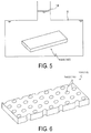
- is an explanatory view illustrating the plate member composing the core member being immersed in the flame retardant and the flame retardant being pressurized according to the first embodiment.
- FIG. 6
- is a perspective view of an aircraft interior panel material of a second embodiment.
- FIG. 7A
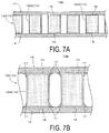
- is a cross-sectional view of the aircraft interior panel material of the second embodiment;
FIG. 7B is an explanatory view illustrating the resin, with which the surface members are impregnated, melted and bonded to surface-area increasing components. - FIG. 8
- is a perspective view of an aircraft interior panel material of a third embodiment.
- FIG. 9
- is a cross-sectional view of the aircraft interior panel material of the third embodiment.
- FIG. 10
- is a perspective view of an aircraft interior panel material of a fourth embodiment.
- FIG. 11
- is a cross-sectional view of the aircraft interior panel material of the fourth embodiment.
- FIG. 12
- is an explanatory view showing the experiment results of a first experiment.
- FIG. 13
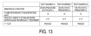
- is an explanatory view showing the experiment results of a second experiment.
- Next, an aircraft
interior panel material 10A of the first embodiment is described with reference toFIGS. 1 to 5 .
"Aircraft interior panel material" broadly refers to a panel material such as a panel material that composes an aircraft lavatory unit, a panel material that composes a galley, a panel material that composes a luggage compartment, and the like.
As illustrated inFIG. 1 , the aircraftinterior panel material 10A includes acore member 12, andsurface members 14 attached to both surfaces of thecore member 12.
Thecore member 12 includes aplate member 12A composed of balsa wood and having a rectangular shape and uniform thickness. Both surfaces of theplate member 12A in the thickness direction are flat surfaces.
Note that the size of a single plate made from a single piece of timber is limited, and so theplate member 12A is constituted by a combination of single plates.
More specifically,single plates 1202 formed in an elongated shape are lined up in the width direction to form theplate member 12A to a desired size. In addition, as well as lining up thesingle plates 1202 in the width direction, thesingle plates 1202 may also be layered in the thickness direction to form theplate member 12A to a desired thickness. In such a case, adjacentsingle plates 1202 may be adhered together at end surfaces thereof by adhesive, and layeredsingle plates 1202 may be adhered together at side surfaces thereof by adhesive.
Balsa wood is light weight and strong and can be easily machined due to its softness. Moreover, balsa wood is a natural material, which means that it is easy to handle in terms of disposal and recycling, therefore assisting in environmental impact reduction.
From the perspective of obtaining a good strength-to-weight ratio, the specific gravity of the balsa wood used is preferably from 0.090 to 0.26, both inclusive, and more preferably from 0.090 to 0.10, both inclusive.
In addition, from the perspective of enhancing strength, the balsa wood is preferably used with the surfaces perpendicular to the grain of the plate (end grain surfaces) as the surfaces of thecore member 12 on which thesurface members 14 are disposed. - As illustrated in
FIG. 2 , both surfaces of theplate member 12A in the thickness direction are impregnated withflame retardant 18, which reduces the flammability of the balsa wood.
Known flame retardants for wood such as phosphoric acid based, boric acid based, silicic acid based, aluminum based, and iron based flame retardants can be used as theflame retardant 18.
Various methods of impregnating both surfaces of theplate member 12A in the thickness direction with theflame retardant 18 can be considered.
For example, asprayer 2 may be used to spray theflame retardant 18 on both surfaces of theplate member 12A, as illustrated inFIG. 3 , or theflame retardant 18 may be applied to both surfaces of theplate member 12A.
Alternatively, theplate member 12A may be immersed in theflame retardant 18 inside acontainer 4, as illustrated inFIG. 4 .
As another alternative, as illustrated inFIG. 5 , theplate member 12A, upon being immersed in theflame retardant 18 in acontainer 6, may be subjected to static pressure larger than the pressure (water pressure) at the depth where theplate member 12A is immersed, or cycles of static pressure larger than the pressure (water pressure) at the depth where theplate member 12A is immersed. By subjecting theplate member 12A to pressure larger than the pressure at the depth where theplate member 12A is immersed, the surfaces of theplate member 12A can be impregnated in a short period of time. As a result, advantages in terms of increasing productivity while maintaining high flame retardancy are obtained. - As illustrated in
FIGS. 1 and 2 , thesurface members 14 have the same shape and dimensions as theplate member 12A and are disposed adhered to both surfaces of theplate member 12A in the thickness direction.
Fiber-reinforced composite material may be used as thesurface members 14. As such a fiber-reinforced composite material, a sheet-like prepreg composed of glass/aramid/carbon fabric or fiber that has been impregnated with phenolic resin or epoxy resin may be used.
In addition, thesurface members 14 are attached to both surfaces of theplate member 12A in the thickness direction by: layering thesurface members 14 on both surfaces of theplate member 12A in the thickness direction, and then applying pressure and heat to thesurface members 14, thereby causing the resin with which thesurface members 14 have been impregnated to thermally cured and adhering thesurface members 14 to both surfaces of theplate member 12A in the thickness direction. - According to the aircraft
interior panel material 10A of the present embodiment, because balsa wood, which is both light weight and strong and easily machined due to its softness, is used as thecore member 12, great advantages in terms of weight reduction of interior components of an aircraft, such as aircraft lavatory units, galleys, luggage compartments, and the like, are obtained.
In addition, because balsa wood, which is inexpensive and easy to handle in terms of disposal and recycling, is used as thecore member 12, advantages in terms of both reducing the cost of the interior components of an aircraft and the environmental impact are obtained.
In addition, because the surfaces of theplate member 12A are impregnated with theflame retardant 18, advantages in terms of ensuring the high flame retardancy of the interior components of an aircraft are obtained. - Next, an aircraft
interior panel material 10B of the second embodiment is described with reference toFIGS. 6 and7A, 7B .
In this embodiment, components identical to those of the first embodiment are assigned identical reference numerals, and detailed descriptions thereof are omitted.
Note that in the following embodiment, the configuration of thecore member 12 is different from that of the first embodiment, and the configurations of the components other than thecore member 12 are similar to those of the first embodiment.
In the second embodiment, a plurality of surface-area increasing components 16 are provided in theplate member 12A that composes thecore member 12. The surface-area increasing components 16 are recessed from the surfaces of theplate member 12A to increase the surface area thereof.
In the present embodiment, each of the surface-area increasing components 16 is constituted by ahole 1602 that passes through theplate member 12A in the thickness direction.
The form of thehole 1602 in theplate member 12A is made using a machining tool such as a drilling machine, for example.
In addition, as illustrated inFIG. 7A , both surfaces of theplate member 12A in the thickness direction and the inner circumferential surfaces of theholes 1602 are impregnated with theflame retardant 18, which reduces the flammability of the balsa wood.
The method of impregnating theplate member 12A with theflame retardant 18 and the attachment of thesurface members 14 to theplate member 12A are similar to that of the first embodiment.
According to the aircraftinterior panel material 10B of the second embodiment, a similar effect as that of the first embodiment is obtained. As well as this effect, advantages in terms of securing greater flame retardancy are obtained because the surface area of theplate member 12A impregnated with theflame retardant 18 is increased. In addition, advantages in terms of further weight reduction of the interior components of an aircraft are obtained by providing a plurality of surface-area increasing components 16 for the purpose of reducing weight of the aircraftinterior panel material 10B.
In addition, because the surface-area increasing components 16 (holes 1602) are recessed from the surfaces of theplate member 12A, the adhesion area therebetween increases. This is because in the case of thesurface members 14, each constituted by a sheet-like prepreg, being layered on both surfaces of theplate member 12A in the thickness direction then thesurface members 14 being adhered to both surfaces of theplate member 12A in the thickness direction by applying pressure and heat, the resin with which thesurface members 14 have been impregnated melts and bonds to the surface of theplate member 12A and the surface-area increasing components 16 (holes 1602). Resin with which thesurface members 14 have been impregnated in the state of being melted and bonded to the surface-area increasing components 16 (holes 1602) is illustrated inFIG. 7B by hatching and thereference sign 17. As a result of this configuration, the adhesive strength between thesurface members 14 and theplate member 12A is enhanced and advantages in terms of ensuring the strength of the aircraftinterior panel material 10B are obtained. - Next, an aircraft
interior panel material 10C of the third embodiment is described with reference toFIGS. 8 and 9 .
In the third embodiment, the configuration of the surface-area increasing component 16 is different from that of the second embodiment, and the configurations of the components other than the surface-area increasing component 16 are similar to those of the second embodiment.
Specifically, the surface-area increasing component 16 is constituted by a recessedportion 1604 with a closed bottom that has depth in the thickness direction of theplate member 12A.
The recessedportion 1604 may be formed on only one surface of theplate member 12A in the thickness direction or may be formed on both surfaces in the thickness direction.
The form of the recessedportion 1604 in theplate member 12A is made using a machining tool such as a drilling machine, for example.
Both surfaces of theplate member 12A in the thickness direction and the inner circumferential surfaces and bottom surfaces of the recessedportions 1604 are impregnated with theflame retardant 18, which reduces the flammability of the balsa wood.
The method of impregnating theplate member 12A with theflame retardant 18 and the attachment of thesurface members 14 to theplate member 12A are similar to those of the first embodiment.
According to the aircraftinterior panel material 10C of the third embodiment, a similar effect as that of the second embodiment is obtained. In addition, because the surface-area increasing components 16 (recessed portions 1604) are recessed from the surfaces of theplate member 12A, the adhesion area therebetween increases. This is because in the case of thesurface members 14, each constituted by a sheet-like prepreg, being layered on both surfaces of theplate member 12A in the thickness direction then thesurface members 14 being adhered to both surfaces of theplate member 12A in the thickness direction by applying pressure and heat, the resin with which thesurface members 14 have been impregnated melts and bonds to the surface of theplate member 12A and the surface-area increasing components 16 (recessed portions 1604). As a result of this configuration, the adhesive strength between thesurface members 14 and theplate member 12A is enhanced and advantages in terms of ensuring the strength of the aircraftinterior panel material 10C are obtained. - Next, an aircraft
interior panel material 10D of the fourth embodiment is described with reference toFIGS. 10 and 11 .
In the fourth embodiment, the configuration of the surface-area increasing component 16 is different from those of the second and third embodiments, and the configurations of the components other than the surface-area increasing component 16 are similar to those of the second and third embodiments.
Specifically, the surface-area increasing component 16 is constituted bygrooves 1610 formed extending in both surfaces of theplate member 12A in the thickness direction.
The form of thegrooves 1610 in theplate member 12A is made using a machining tool such as a milling machine, for example.
Both surfaces (outer surfaces) of theplate member 12A in the thickness direction and the surface of the plurality ofgrooves 1610 are impregnated with theflame retardant 18, which reduces the flammability of the balsa wood.
Both surfaces of theplate member 12A in the thickness direction and the surface of thegrooves 1610 are impregnated with theflame retardant 18, which reduces the flammability of the balsa wood.
The method of impregnating theplate member 12A with theflame retardant 18 and the attachment of thesurface members 14 to theplate member 12A are similar to those of the first embodiment. - Note that in the fourth embodiment, as illustrated in
FIG. 11 , thegrooves 1610 formed extending in one surface of theplate member 12A in the thickness direction that faces asurface member 14 are offset from thegrooves 1610 formed extending in the other surface in a manner such that thegrooves 1610 are located alternating in position in the direction perpendicular to the extension direction thegrooves 1610. Consequently, advantages in terms of maintaining uniform thickness and strength of thecore member 12 are obtained. - According to the aircraft
interior panel material 10D of the fourth embodiment, a similar effect as those of the second and third embodiments is of course obtained. In addition, advantages in terms of cost and machining time reduction are obtained compared to the case, such as in the second and third embodiments, in which a drilling machine is used to form theholes 1602 or recessedportions 1604 in theplate member 12A because a milling machine can be used to form thegrooves 1610 in theplate member 12A in a short period of time.
In addition, because the surface-area increasing components 16 (grooves 1610) are recessed from the surfaces of theplate member 12A, the adhesion area therebetween increases. This is because in the case of thesurface members 14, each constituted by a sheet-like prepreg, being layered on both surfaces of theplate member 12A in the thickness direction then thesurface members 14 being adhered to both surfaces of theplate member 12A in the thickness direction by applying pressure and heat, the resin thesurface members 14 have been impregnated melts and bonds to the surface of theplate member 12A and the surface-area increasing components 16 (grooves 1610). As a result of this configuration, the adhesive strength between thesurface members 14 and theplate member 12A is enhanced and advantages in terms of ensuring the strength of the aircraftinterior panel material 10D are obtained. - Note that in the description of the second to fourth embodiments, the surface-
area increasing component 16 constituted by any one of: thehole 1602, the recessedportion 1604, and thegroove 1610 is described. However, the surface-area increasing components 16 may be constituted by any one of thehole 1602, the recessedportion 1604, and thegroove 1610 or by a combination thereof. - Next, experiment results relating to the aircraft interior panel material of the present embodiment is explained.
A first experiment and second experiment were performed as described below.
The first experiment was a flammability test for the case in which the surfaces of theplate member 12A were impregnated with the flame retardant by immersing theplate member 12A in a solution of the flame retardant and applying no pressure load to theplate member 12A.
The second experiment was a flammability test for the case in which the surfaces of theplate member 12A were impregnated with the flame retardant by immersing theplate member 12A in a solution of the flame retardant then applying a large water pressure to the solution. - In the first experiment, sample aircraft
interior panel materials 10A according to the first embodiment were manufactured as described below. The samples were tested via the vertical flammability test (hereafter referred to as "F1 test") for 60 seconds as specified in the Federal Aviation Regulations (FAR) 25.853 Appendix F Part I (a)(i). The results of the aircraftinterior panel materials 10A satisfied the flame retardancy requirements.
Passing requirements for the F1 test was a self-extinguishing time of 15 seconds or less, a burn length of 6 inches or less, and flaming time of drippings of 3 seconds or less.
The manufactured aircraftinterior panel materials 10A were configured as follows.
Rectangular plate-like plate members 12A 31 x 8 cm in size, 1 cm thick, and with a specific gravity of approximately 0.1 were immersed in solutions of boric acid based flame retardant of different concentrations for 24 hours, thereby impregnating the surfaces of theplate members 12A with the flame retardant. The resulting specific gravity of thecore members 12 was from 0.11 to 0.16, both inclusive. - Next, the above-described flammability test is described in detail.
- Specific gravity of
plate member 12A prior to treatment: 0.098 -
Plate member 12A trade name: BALTEK® SB (SB.50) -
Plate member 12A manufacturer: 3A Composites -
Flame retardant 18 trade name: Fireless B® -
Flame retardant 18 manufacturer: TRUST LIFE CORPORATION -
Core member 12 treatment method after immersion in solution offlame retardant 18 of each concentration: Dried at room temperature - In the flammability test described above, as illustrated in
FIG. 12 , the concentration of theflame retardant 18 was varied to manufacture the flammability test samples of Test Example 1 to 3.
Note that the flammability test samples are each constituted by thecore member 12 impregnated with theflame retardant 18 described above, and thesurface members 14 described below adhered to both surfaces of thecore member 12.
Surface members 14: Glass/phenolic prepreg
As indicated inFIG. 12 , the Test Examples 1, 2, and 3 passed the F1 test. - In the second experiment, sample aircraft
interior panel materials 10A according to the first embodiment were manufactured under the immersion conditions described below. The samples were tested via the F1 test in a similar manner to that of the first experiment. The results of the aircraftinterior panel materials 10A satisfied the flame retardancy requirements. The manufactured aircraftinterior panel materials 10A were configured as follows. - Rectangular plate-
like plate members 12A 31 x 8 cm in size, 1 cm thick, and with a specific gravity of approximately 0.1 were immersed in a solution of boric acid based flame retardant of 10 wt% concentration under the immersion conditions described below, thereby impregnating the surfaces of theplate members 12A with the flame retardant. The resulting specific gravity of thecore members 12 was approximately 0.11.
The details of the above-described flammability test are similar to that of the first experiment.
In the flammability test described above, as illustrated inFIG. 13 , the immersion conditions were varied to manufacture the flammability test samples of Test Example 4 to 6.
Note that the flammability test samples, in a similar manner to that of the first experiment, are each constituted by thecore member 12 impregnated with theflame retardant 18 described above, and glass/phenolicprepreg surface members 14 adhered to both surfaces of thecore member 12. - Immersion conditions were as follows.
Test Example 4: As illustrated inFIG. 5 , theplate member 12A was immersed in theflame retardant 18 inside thecontainer 6, and water pressure of 50 kPa was applied for 5 minutes. Then, the loaded water pressure was removed for 1 minute. This cycle was repeated for 4 hours. Test Example 5: Theplate member 12A was immersed in theflame retardant 18 inside thecontainer 6, and water pressure (static pressure) of 50 kPa was applied for 4 hours.
Test Example 6: Theplate member 12A was immersed in theflame retardant 18 inside thecontainer 6, and water pressure (static pressure) of 100 kPa was applied for 2 hours.
As indicated inFIG. 13 , the Test Examples 4, 5, and 6 passed the F1 test. It is clear from the results that by immersing theplate member 12A in a solution of theflame retardant 18 and then applying a large water pressure to the solution, the surfaces of theplate member 12A can be impregnated with theflame retardant 18 in a short period of time (approximately 2 to 4 hours), resulting in advantages in terms of increasing productivity while maintaining the flame retardancy of the aircraftinterior panel material 10A. -
- 10A, 10B, 10C, 10D Aircraft interior panel material
- 12 Core member
- 12A Plate member
- 14 Surface member
- 16 Surface-area increasing component
- 1602 Hole
- 1604 Recessed portion
- 1610 Groove
- 18 Flame retardant
Claims (7)
- An aircraft interior panel material comprising:a core member; andsurface members including fiber-reinforced composite material, the surface members being attached to both surfaces of the core member, whereinthe core member includes a plate member composed of balsa wood; and
both surfaces of the plate member are impregnated with a flame retardant. - The aircraft interior panel material according to claim 1, wherein
each of the surfaces of the plate member is provided with a plurality of surface-area increasing components recessed from the surface and configured to increase the surface area of the surface. - The aircraft interior panel material according to claim 2, wherein
the surface-area increasing components are constituted by any one of: a hole passing through the plate member in a thickness direction thereof, a recessed portion with a closed bottom that has depth in the thickness direction of the plate member, and grooves formed extending in both surfaces of the plate member in the thickness direction of the plate member; or a combination thereof. - A method of manufacturing an aircraft interior panel material provided with surface members including fiber-reinforced composite material attached to both surfaces of a core member, wherein
both surfaces of a plate member to be used as the core member are impregnated with flame retardant. - The method of manufacturing an aircraft interior panel material according to claim 4, further comprising:disposing a plurality of surface-area increasing components in each of the surfaces of the plate member prior to impregnation of the surfaces of the plate member with the flame retardant, the surface-area increasing components being recessed from the surface and configured to increase the surface area of the surface.
- The method of manufacturing an aircraft interior panel material according to claim 5, wherein
the attaching of the surface members to both surfaces of the core member is performed by:upon the surface members being layered on both surfaces of the core member, melting resin with which the surface members have been impregnated by applying pressure and heat to bond the resin to the surfaces of the plate member and the surface-area increasing components. - The method of manufacturing an aircraft interior panel material according to any one of claims 4 to 6, wherein
the impregnation of the surfaces of the plate member with the flame retardant is performed by:upon immersing the plate member in the flame retardant and applying a pressure larger than a pressure at a depth where the plate member is immersed to the plate member, maintaining this state for a predetermined period of time.
Applications Claiming Priority (3)
| Application Number | Priority Date | Filing Date | Title |
|---|---|---|---|
| JP2013207834 | 2013-10-03 | ||
| JP2014078369 | 2014-04-07 | ||
| PCT/JP2014/076508 WO2015050239A1 (en) | 2013-10-03 | 2014-10-03 | Aircraft interior panel material and manufacturing method therefor |
Publications (2)
| Publication Number | Publication Date |
|---|---|
| EP3053829A1 true EP3053829A1 (en) | 2016-08-10 |
| EP3053829A4 EP3053829A4 (en) | 2017-06-07 |
Family
ID=52778822
Family Applications (1)
| Application Number | Title | Priority Date | Filing Date |
|---|---|---|---|
| EP14850209.9A Withdrawn EP3053829A4 (en) | 2013-10-03 | 2014-10-03 | Aircraft interior panel material and manufacturing method therefor |
Country Status (4)
| Country | Link |
|---|---|
| US (1) | US20160264229A1 (en) |
| EP (1) | EP3053829A4 (en) |
| JP (1) | JPWO2015050239A1 (en) |
| WO (1) | WO2015050239A1 (en) |
Cited By (1)
| Publication number | Priority date | Publication date | Assignee | Title |
|---|---|---|---|---|
| CN107718265A (en) * | 2016-08-11 | 2018-02-23 | 南通奥王节能建筑材料科技发展有限公司 | A kind of sound-absorbing integrated board and preparation method thereof |
Families Citing this family (3)
| Publication number | Priority date | Publication date | Assignee | Title |
|---|---|---|---|---|
| US11426983B2 (en) * | 2019-04-19 | 2022-08-30 | Goodrich Corporation | Carbon fiber decorative veneer |
| US20210024196A1 (en) * | 2019-07-25 | 2021-01-28 | Gulfstream Aerospace Corporation | Aircraft, interior panels for aircfraft, and methods for making interior panels |
| JP7557132B2 (en) | 2020-09-29 | 2024-09-27 | キョーラク株式会社 | Resin Panel |
Family Cites Families (14)
| Publication number | Priority date | Publication date | Assignee | Title |
|---|---|---|---|---|
| US4428993A (en) * | 1982-05-11 | 1984-01-31 | Baltek Corporation | Structural laminate with expanded wood core |
| US4741971A (en) * | 1986-05-23 | 1988-05-03 | The Dow Chemical Company | Method for imparting flame resistance to wood surfaces |
| JPH05309792A (en) * | 1992-05-14 | 1993-11-22 | Hamaguchi Keiki Kogyo Kk | Frp composite panel and production thereof |
| JP2000238154A (en) | 1999-02-19 | 2000-09-05 | Toray Ind Inc | Honeycomb sandwich panel |
| JP4066310B2 (en) * | 2001-11-14 | 2008-03-26 | 東レ株式会社 | FRP automobile panel and manufacturing method thereof |
| JP3538194B2 (en) * | 2001-11-16 | 2004-06-14 | 浅野木材工業株式会社 | Production method of noncombustible wood |
| JP2006002869A (en) * | 2004-06-18 | 2006-01-05 | Toho Tenax Co Ltd | Sandwich panel |
| JP2006175606A (en) * | 2004-12-20 | 2006-07-06 | Toyota Motor Corp | Insert for FRP |
| DE102006058445B3 (en) * | 2006-12-10 | 2008-06-19 | Moralt Tischlerplatten Gmbh & Co.Kg | Lightweight panel and manufacturing process |
| JP2010095943A (en) * | 2008-10-17 | 2010-04-30 | Ihi Corp | Sandwich panel |
| EP2463083B1 (en) * | 2010-12-13 | 2016-06-29 | The Boeing Company | Green aircraft interior panels and method of fabrication |
| EP2788409B1 (en) * | 2011-12-05 | 2016-02-24 | Csir | A flame-proofed artefact and a method of manufacture thereof |
| EP2894136B1 (en) * | 2014-01-08 | 2019-12-04 | The Boeing Company | Improved method of making fire resistant sustainable aircraft interior panels |
| EP2894029B1 (en) * | 2014-01-08 | 2017-04-12 | The Boeing Company | Fire resistant sustainable aircraft interior panel |
-
2014
- 2014-10-03 JP JP2015540565A patent/JPWO2015050239A1/en active Pending
- 2014-10-03 US US15/026,933 patent/US20160264229A1/en not_active Abandoned
- 2014-10-03 EP EP14850209.9A patent/EP3053829A4/en not_active Withdrawn
- 2014-10-03 WO PCT/JP2014/076508 patent/WO2015050239A1/en not_active Ceased
Cited By (1)
| Publication number | Priority date | Publication date | Assignee | Title |
|---|---|---|---|---|
| CN107718265A (en) * | 2016-08-11 | 2018-02-23 | 南通奥王节能建筑材料科技发展有限公司 | A kind of sound-absorbing integrated board and preparation method thereof |
Also Published As
| Publication number | Publication date |
|---|---|
| WO2015050239A1 (en) | 2015-04-09 |
| EP3053829A4 (en) | 2017-06-07 |
| JPWO2015050239A1 (en) | 2017-03-09 |
| US20160264229A1 (en) | 2016-09-15 |
Similar Documents
| Publication | Publication Date | Title |
|---|---|---|
| EP2463083B1 (en) | Green aircraft interior panels and method of fabrication | |
| CN102448814B (en) | Structure for assembly of the pressure bulkhead of an aircraft | |
| RU2401949C2 (en) | Device intended for attachment of light panel on support element | |
| RU2466905C2 (en) | Skin element as aircraft fuselage part | |
| US20160264229A1 (en) | Aircraft Interior Panel Material and Manufacturing Method Therefor | |
| JP2016512589A (en) | FIXING METHOD TO PANEL HAVING INSERT AND CORE | |
| CA2615783A1 (en) | Fire retardant panel apparatus and method of making and using same | |
| US20130243998A1 (en) | Sandwich component | |
| US20080233344A1 (en) | Airplane component as well as method for manufacturing an airplane component | |
| JP2011131628A5 (en) | ||
| US20150190973A1 (en) | Method of making fire resistant sustainable aircraft interior panels | |
| RU2573002C2 (en) | Part for rail-mounted vehicles | |
| CA2834323A1 (en) | Flight vehicle fairing having vibration-damping blankets | |
| US20090286040A1 (en) | Impact Resistant Core | |
| EP3453525B1 (en) | Method and apparatus for manufacturing stiffened composite sandwich panels | |
| JP2021195121A (en) | Composite door and method of forming the same | |
| US9567754B2 (en) | Flooring assembly with heat dissipation layer | |
| US9211943B2 (en) | Interior equipment element for vehicle cabins | |
| US20180282129A1 (en) | Planar elevator car element for an elevator installation | |
| DE102020002099B4 (en) | Vacuum insulation panel with at least one support layer, interior trim panel with the vacuum insulation panel and aircraft with the interior trim panel and / or the vacuum insulation panel | |
| NL2015889B1 (en) | A stitch-reinforced sandwich panel. | |
| US8962497B2 (en) | Fire resistant component | |
| EP3248774B1 (en) | Fireproof polymer matrix composite structure | |
| WO2022202167A1 (en) | Case structure and battery case | |
| US20190084254A1 (en) | Fiber composite component and production method |
Legal Events
| Date | Code | Title | Description |
|---|---|---|---|
| PUAI | Public reference made under article 153(3) epc to a published international application that has entered the european phase |
Free format text: ORIGINAL CODE: 0009012 |
|
| 17P | Request for examination filed |
Effective date: 20160503 |
|
| AK | Designated contracting states |
Kind code of ref document: A1 Designated state(s): AL AT BE BG CH CY CZ DE DK EE ES FI FR GB GR HR HU IE IS IT LI LT LU LV MC MK MT NL NO PL PT RO RS SE SI SK SM TR |
|
| AX | Request for extension of the european patent |
Extension state: BA ME |
|
| DAX | Request for extension of the european patent (deleted) | ||
| A4 | Supplementary search report drawn up and despatched |
Effective date: 20170508 |
|
| RIC1 | Information provided on ipc code assigned before grant |
Ipc: D06M 11/71 20060101ALI20170428BHEP Ipc: C04B 28/24 20060101ALI20170428BHEP Ipc: C04B 30/02 20060101ALI20170428BHEP Ipc: B32B 5/02 20060101ALI20170428BHEP Ipc: B28B 19/00 20060101ALI20170428BHEP Ipc: D06M 15/227 20060101ALI20170428BHEP Ipc: B32B 5/24 20060101ALI20170428BHEP Ipc: D06M 23/08 20060101ALI20170428BHEP Ipc: D06M 11/82 20060101ALI20170428BHEP Ipc: B29D 99/00 20100101ALI20170428BHEP Ipc: B28B 23/00 20060101ALI20170428BHEP Ipc: B32B 21/08 20060101ALI20170428BHEP Ipc: B64D 11/00 20060101AFI20170428BHEP Ipc: B29C 70/34 20060101ALI20170428BHEP Ipc: C04B 28/00 20060101ALI20170428BHEP |
|
| STAA | Information on the status of an ep patent application or granted ep patent |
Free format text: STATUS: THE APPLICATION IS DEEMED TO BE WITHDRAWN |
|
| 18D | Application deemed to be withdrawn |
Effective date: 20190501 |