EP3053823B1 - Flugzeug mit einem unterbodenabschnitt zur unterbringung eines zusatzfachs - Google Patents
Flugzeug mit einem unterbodenabschnitt zur unterbringung eines zusatzfachs Download PDFInfo
- Publication number
- EP3053823B1 EP3053823B1 EP15400006.1A EP15400006A EP3053823B1 EP 3053823 B1 EP3053823 B1 EP 3053823B1 EP 15400006 A EP15400006 A EP 15400006A EP 3053823 B1 EP3053823 B1 EP 3053823B1
- Authority
- EP
- European Patent Office
- Prior art keywords
- fuel tank
- crash
- aircraft
- equipment
- compartment
- Prior art date
- Legal status (The legal status is an assumption and is not a legal conclusion. Google has not performed a legal analysis and makes no representation as to the accuracy of the status listed.)
- Active
Links
- 239000002828 fuel tank Substances 0.000 claims description 103
- 238000013016 damping Methods 0.000 description 9
- 239000000446 fuel Substances 0.000 description 6
- 238000010276 construction Methods 0.000 description 3
- 230000010354 integration Effects 0.000 description 3
- 238000012384 transportation and delivery Methods 0.000 description 3
- 230000004308 accommodation Effects 0.000 description 2
- 230000007423 decrease Effects 0.000 description 2
- 230000003247 decreasing effect Effects 0.000 description 2
- 230000000694 effects Effects 0.000 description 2
- 230000002349 favourable effect Effects 0.000 description 2
- 239000000463 material Substances 0.000 description 2
- 238000000926 separation method Methods 0.000 description 2
- 239000002023 wood Substances 0.000 description 2
- 238000010521 absorption reaction Methods 0.000 description 1
- 230000001668 ameliorated effect Effects 0.000 description 1
- 150000001875 compounds Chemical class 0.000 description 1
- 230000004048 modification Effects 0.000 description 1
- 238000012986 modification Methods 0.000 description 1
- 239000003381 stabilizer Substances 0.000 description 1
- 239000002699 waste material Substances 0.000 description 1
Images


Classifications
-
- B—PERFORMING OPERATIONS; TRANSPORTING
- B64—AIRCRAFT; AVIATION; COSMONAUTICS
- B64C—AEROPLANES; HELICOPTERS
- B64C1/00—Fuselages; Constructional features common to fuselages, wings, stabilising surfaces or the like
- B64C1/18—Floors
-
- B—PERFORMING OPERATIONS; TRANSPORTING
- B64—AIRCRAFT; AVIATION; COSMONAUTICS
- B64C—AEROPLANES; HELICOPTERS
- B64C1/00—Fuselages; Constructional features common to fuselages, wings, stabilising surfaces or the like
- B64C1/06—Frames; Stringers; Longerons ; Fuselage sections
- B64C1/061—Frames
- B64C1/062—Frames specially adapted to absorb crash loads
-
- B—PERFORMING OPERATIONS; TRANSPORTING
- B64—AIRCRAFT; AVIATION; COSMONAUTICS
- B64D—EQUIPMENT FOR FITTING IN OR TO AIRCRAFT; FLIGHT SUITS; PARACHUTES; ARRANGEMENTS OR MOUNTING OF POWER PLANTS OR PROPULSION TRANSMISSIONS IN AIRCRAFT
- B64D1/00—Dropping, ejecting, releasing, or receiving articles, liquids, or the like, in flight
- B64D1/22—Taking-up articles from earth's surface
-
- B—PERFORMING OPERATIONS; TRANSPORTING
- B64—AIRCRAFT; AVIATION; COSMONAUTICS
- B64D—EQUIPMENT FOR FITTING IN OR TO AIRCRAFT; FLIGHT SUITS; PARACHUTES; ARRANGEMENTS OR MOUNTING OF POWER PLANTS OR PROPULSION TRANSMISSIONS IN AIRCRAFT
- B64D37/00—Arrangements in connection with fuel supply for power plant
- B64D37/02—Tanks
- B64D37/04—Arrangement thereof in or on aircraft
-
- B—PERFORMING OPERATIONS; TRANSPORTING
- B64—AIRCRAFT; AVIATION; COSMONAUTICS
- B64D—EQUIPMENT FOR FITTING IN OR TO AIRCRAFT; FLIGHT SUITS; PARACHUTES; ARRANGEMENTS OR MOUNTING OF POWER PLANTS OR PROPULSION TRANSMISSIONS IN AIRCRAFT
- B64D45/00—Aircraft indicators or protectors not otherwise provided for
-
- B—PERFORMING OPERATIONS; TRANSPORTING
- B64—AIRCRAFT; AVIATION; COSMONAUTICS
- B64D—EQUIPMENT FOR FITTING IN OR TO AIRCRAFT; FLIGHT SUITS; PARACHUTES; ARRANGEMENTS OR MOUNTING OF POWER PLANTS OR PROPULSION TRANSMISSIONS IN AIRCRAFT
- B64D9/00—Equipment for handling freight; Equipment for facilitating passenger embarkation or the like
Definitions
- the invention is related to an aircraft with a fuselage and a floor structure that is arranged inside said fuselage, said floor structure accommodating at least one auxiliary compartment, said aircraft comprising the features of claim 1.
- Aircrafts and, more particularly, rotorcrafts such as helicopters or hybrid aircrafts, such as e. g. tilt-rotors, compound aircrafts, are commonly used to fulfill aerial transportation and delivery tasks, starting from passenger transport to disaster reliefs up to carrying all kind of external loads.
- helicopters are used to transport and deliver loads to mountain regions in general and, more specifically, to mountain regions where no roads exist or where roads cannot be used for transportation and delivery, e. g. due to extreme weather conditions in winter and so on.
- helicopters are used for transportation and delivery of loads or in the construction sector, where the loads may represent any kind of material.
- helicopters can be used in firefighting for transportation of firefighting buckets.
- helicopters are also very useful in wood logging for transporting harvested wood. In all of these cases, the helicopters can be required to transport comparatively heavy external loads which can, depending on an underlying type of helicopter, weigh up to several tons.
- the helicopter can be equipped with a cargo hook arrangement to which an external load mass rope for connection to the external load can be attached.
- a given external load can be suspended from the helicopter by means of the external load mass rope, which is particularly useful for bulky loads which do not fit into the cabin of the helicopter.
- such a cargo hook arrangement is attached to the helicopter's landing skid.
- a helicopter having such a cargo hook arrangement attached to its landing skid is described in the document WO 2012/037595 A1 .
- attaching the cargo hook arrangement respectively a given bracketing or structural support thereof externally to the helicopter's landing skid is aerodynamically disadvantageous, as an undesired additional drag will be produced in operation, as well as unfavorable flight mechanics in the worst case.
- such a cargo hook arrangement is installed below the fuselage of the helicopter, i. e. at an underside of the fuselage in an area of a subfloor region of the helicopter.
- This subfloor region is defined between a floor structure of the helicopter that is arranged inside the helicopter and a fuselage underside of the fuselage and can generally be used to accommodate one or more auxiliary compartments, such as fuel tanks of the helicopter.
- auxiliary compartments such as fuel tanks of the helicopter.
- the document US 5,451,015 describes a helicopter with a fuel tank arrangement that is accommodated in its subfloor region.
- a corresponding helicopter having such a cargo hook arrangement attached to its fuselage is e. g. described in the documents EP 2 168 871 A1 , US 8,534,608 B1 and US 2013/0054054 A1 .
- the cargo hook arrangement introduces all loads such as sling loads, crash loads or any other applied loads into the mainframe of the helicopter via the helicopter's subfloor frame structure.
- the subfloor region is ideally designed without any disturbing factors.
- one exemplary disturbing factor is the externally mounted cargo hook arrangement, which is attached to the fuselage underside protruding from the helicopter's outer shell and any fuel tanks placed inside the subfloor region.
- the cargo hook arrangement can be arranged inside an equipment bay, which is integrated into the subfloor region of the helicopter instead of the one or more auxiliary compartments described above.
- the document US 5,850,991 describes such a helicopter with a cargo hook arrangement, which is deployable from an associated equipment bay in operation for carrying external loads, and stowable inside the equipment bay when not in use.
- the associated equipment bay is installed in the subfloor region of the helicopter such that loads introduced from the cargo hook arrangement are transferred to an adjacent subfloor frame structure.
- the associated equipment bay can be accessed from inside the helicopter via a removable floor panel.
- the integration of the associated equipment bay into the subfloor region leads to a significant decrease in an effective fuel tank volume of the helicopter, as the complete subfloor region is used to accommodate the equipment bay, i. e. the cargo hook arrangement.
- the cargo hook arrangement may protrude into the inside of the helicopter, thereby endangering crew members.
- the document US 4,893,767 describes another helicopter with a cargo hook arrangement, wherein the latter is mainly installed inside the helicopter.
- a cargo hook that is attached to a cable, which can be deployed out of the helicopter through a cable and equipment guide that is integrated in the form of a funnel respectively through hole into the helicopter's fuselage.
- the integration of the cable and equipment guide into the helicopter's fuselage leads at least to a reduction of available subfloor space for the integration of fuel tanks, so that an effective fuel tank volume of the helicopter is also decreased significantly.
- helicopters with externally mounted cargo hook arrangements will have disadvantages in crash situations, where the cargo hook arrangements hit the ground first.
- the crash loads will be transferred to the fuselage mainframe and the cargo hook arrangement will protrude into the helicopter's subfloor region, which commonly comprises fuel tanks, if a given critical area is not protected by an additional structure.
- the externally mounted cargo hook arrangements and, more generally any externally attached equipment does not only affect the crashworthiness of the helicopters, but consequently lead to higher certification efforts.
- such externally mounted cargo hook arrangements do not provide for a favorable aerodynamic influence since they produce additional drag in operation, leading to increased fuel consumption, reduced velocity or higher required power to reach the intended velocities.
- cargo hook arrangements that are mounted in associated equipment bays in the helicopter's subfloor region provide for ameliorated aerodynamics and are favorable during crash situations, since the subfloor mainframe will hit the ground first and absorb the crash loads.
- there is a major disadvantage consisting in a lack of space for accommodating fuel tanks.
- the provision of such equipment bays reduces the fuel tank volume significantly so that the helicopter comprises less fuel than it could if the subfloor region would be used entirely for the fuel tank volume.
- the documents US 20101012781 A1 and FR 2 933 375 A1 illustrate in their figures 2 respectively an aircraft with a fuselage and a floorboard that is arranged inside the fuselage.
- the floorboard and the fuselage define a subfloor region between the floorboard and a fuselage underside of the fuselage.
- the subfloor region accommodates a cargo compartment with electronic cabinets, wherein a landing gear compartment with a landing gear is arranged within the subfloor region, the landing gear being stowable in the landing gear compartment in a stow mode.
- the cargo compartment and, more specifically, the electronic cabinets are at least partly arranged in a region between the landing gear compartment and the floorboard such that the cargo compartment, i. e. the electronic cabinets, separate the landing gear compartment from the floorboard.
- an object of the present invention to provide a new helicopter and, more generally, a new aircraft with a crashworthy subfloor region, wherein a crashworthy equipment bay with an auxiliary equipment is integrated that has minimal effect on underlying aerodynamics of the aircraft and that does not unnecessarily waste fuel tank volume.
- an aircraft with a fuselage and a floor structure that is arranged inside the fuselage wherein the floor structure and the fuselage define a subfloor region between the floor structure and a fuselage underside of said fuselage, and wherein the subfloor region accommodates at least one auxiliary compartment.
- the aircraft comprises an equipment bay with at least one auxiliary equipment that is arranged within the subfloor region.
- the at least one auxiliary equipment is at least essentially stowable in the equipment bay in a stow mode.
- the at least one auxiliary compartment is at least partly arranged in a region between the equipment bay and the floor structure such that the at least one auxiliary compartment separates the equipment bay from the floor structure.
- the at least one auxiliary equipment is forcibly moveable in the equipment bay in a crash load case from a stow position associated with the stow mode into at least one crash position associated with a crash mode of the at least one auxiliary equipment in order to protect at least said at least one auxiliary compartment and to diminish loads applied to said at least one auxiliary equipment in the crash load case.
- the expression "at least essentially stowable in the stow mode” preferably refers to a continuous and durable accommodation of the at least one auxiliary equipment in the equipment bay.
- the at least one auxiliary equipment is not intended to be retracted from the equipment bay for operation or utilization and to be restowed therein afterwards.
- the at least one auxiliary equipment is preferably accommodated in the equipment bay such that it may at most adjust its stow position in the equipment bay to an operation position that is required for utilization or operation thereof.
- the subfloor region of the aircraft defines a storage space which is positioned below the floor structure of the aircraft, on which passengers, crew members, loads and equipment etc. are placed.
- the subfloor region on the other hand is used for material such as fuel, fuel system, avionics, computers and cargo hook arrangements, which is storable in the inventive auxiliary compartment and/or equipment bay.
- the subfloor region is adapted to protect the passengers and crew members in case of crash incidences. Therefore, the subfloor region comprises structural elements, which must be able to absorb the energy occurring in a crash, and which are commonly called "primary structure". This primary structure is comprised of essentially transversal and essentially longitudinal frame components that are adapted for providing structural stiffness as well as for withstanding all loads that are applied to the aircraft.
- the subfloor region preferably comprises a subfloor height that is selected from a range between 0.04 times and 0.56 times of a fuselage width of the aircraft.
- the fuselage width is defined by a maximum distance measured orthogonally to a longitudinal mid-plane of the aircraft between respective outmost lateral left hand and right hand side fuselage surfaces.
- the subfloor height preferentially amounts to 0.26 times of the fuselage width.
- the at least one auxiliary compartment comprises a compartment height that is selected from a range between 0.03 times and 0.9 times of the subfloor height, and preferentially amounts to 0.5 times of said subfloor height.
- the equipment bay comprises a height that amounts at least to the difference between the subfloor height and the compartment height.
- a distance between the fuselage underside and a lower end of the at least one auxiliary equipment positioned in the stow mode adjacent to the fuselage underside is selected from a range between -0.95 times and 0.35 times of the subfloor height, and preferentially amounts to 0.05 times of the subfloor height.
- the equipment bay comprises a length that is selected from a range between 0.05 times and 0.8 times of the fuselage width, and preferentially amounts to 0.3 times of the fuselage width.
- the aircraft is embodied as a rotorcraft and, in particular, as a helicopter.
- the equipment bay is preferably embodied as a cargo hook compartment that accommodates an associated cargo hook arrangement as auxiliary equipment.
- the present invention is not limited to an accommodation of a cargo hook arrangement in the equipment bay of the inventive helicopter and that other auxiliary equipment can likewise be installed therein, such as e. g. a machine gun, one or more sling load cameras, lights, radars and so on.
- the cargo hook arrangement is at least essentially and, preferably, completely stowable in the cargo hook compartment in the stow mode.
- the at least one auxiliary compartment is arranged within said subfloor region and at least partly arranged in a region between the equipment bay and the floor structure, as well as being implemented as a fuel tank.
- the subfloor region of the inventive helicopter comprises several fuel tanks, wherein the auxiliary compartment is embodied as at least one additional fuel tank that is arranged on top of the cargo hook compartment, i. e. between the cargo hook compartment and the helicopter's floor structure.
- a fuel tank arrangement can be accommodated in the subfloor region, which comprises e. g. one or more front fuel tanks, one or more rear fuel tanks, one or more lateral fuel tanks on each side of the cargo hook compartment and one or more top fuel tanks on top of the cargo hook compartment.
- the cargo hook arrangement submerges in case of a crash of the inventive helicopter preferably entirely into the cargo hook compartment in order to protect at least the top fuel tank, but preferentially also all other fuel tanks in the subfloor region, as well as to diminish any loads applied to the cargo hook arrangement during the crash.
- the cargo hook arrangement is only minimally influenced by occurring crash loads, so that fewer efforts for certification of the cargo hook arrangement are to be expected.
- the crash loads that are applied to the subfloor primary structure of the inventive helicopter during the crash can at least be reduced.
- crash loads that are applied during a crash of the helicopter to its fuselage as such can be absorbed or at least reduced according to the present invention in order to prevent any structural impact on the subfloor primary structure.
- the subfloor primary structure in the area of the cargo hook arrangement can be provided with less weight compared to the conventional primary structure, since the crash loads transferred from the cargo hook arrangement to the subfloor primary structure are reduced. This, in turn, leads to less total weight of the inventive helicopter and, hence, to a more efficient helicopter.
- the submerging of the cargo hook arrangement into the cargo hook compartment can be achieved by means of a rotation of the cargo hook arrangement during a crash, so that the cargo hook arrangement is deflected on one side and, thus, reduces its vertical extension, or by an absorption of crash forces acting on the cargo hook arrangement by means of the crash fuse element, which will consequently break in case of a crash.
- the submerging can be achieved via suitable damping means or by means of a suitable load absorbing attachment.
- the equipment bay comprises at least one outer wall that separates the at least one auxiliary equipment from the at least one auxiliary compartment.
- the subfloor region is provided with a crashworthy frame structure defined by transversal frame components and longitudinal frame components.
- the at least one auxiliary equipment is mounted to predetermined transversal and/or longitudinal frame components of the crashworthy frame structure.
- the at least one auxiliary equipment is rotatably mounted to the predetermined transversal and/or longitudinal frame components.
- the at least one auxiliary equipment comprises a shaft that is mounted to the predetermined transversal and/or longitudinal frame components of the crashworthy frame structure.
- the shaft is a rotation shaft that defines a rotation axis, and that is rotatably mounted to the predetermined transversal and/or longitudinal frame components.
- the rotation axis of the rotation shaft of the at least one auxiliary equipment is arranged in the equipment bay at a distance from the fuselage underside that is preferably smaller than the height of the equipment bay.
- the at least one auxiliary equipment is forcibly rotatable around the rotation axis of the above mentioned rotation shaft in the equipment bay.
- the shaft is mounted to the predetermined transversal and/or longitudinal frame components of the crashworthy frame structure by means of structural frame attachments.
- the shaft is a rotation shaft that is rotatably mounted to the predetermined transversal and/or longitudinal frame components.
- At least one of the structural frame attachments is provided with a crash fuse mount that holds the shaft.
- the crash fuse mount is adapted for absorbing energy in a crash load case.
- the shaft is a rotation shaft and the crash fuse mount holds the rotation shaft.
- the crash fuse mount comprises at least one crash fuse element that is provided with predetermined breaking points.
- the predetermined breaking points are adapted for breaking in the crash load case.
- the structural frame attachments are mounted to the predetermined transversal and/or longitudinal frame components of the crashworthy frame structure by means of associated fixation means.
- the equipment bay comprises an access door for closing the equipment bay in the stow mode, preferably sealingly.
- a plurality of fuel tanks is arranged around the equipment bay within the subfloor region, wherein the at least one auxiliary compartment defines a top fuel tank.
- the equipment bay is arranged within the subfloor region on the side of at least one lateral fuel tank, wherein the at least one auxiliary compartment defines a top fuel tank that is an integral part of the at least one lateral fuel tank.
- the equipment bay is separated from the at least one lateral fuel tank by at least one longitudinal frame component.
- the equipment bay is arranged within the subfloor region behind at least one front fuel tank and/or in front of at least one rear fuel tank, wherein the at least one auxiliary compartment defines a top fuel tank that is an integral part of the at least one front fuel tank and/or the at least one rear fuel tank.
- the equipment bay is separated from the at least one front fuel tank and/or the at least one rear fuel tank by at least one transversal frame component.
- the at least one auxiliary equipment is a cargo hook arrangement, wherein the equipment bay defines a cargo hook compartment.
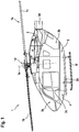
- Figure 1 shows an aircraft 1 according to one aspect of the present invention, which comprises a fuselage 2 with a subfloor region 4.
- the aircraft 1 is exemplarily embodied as a rotary-wing aircraft and, more particularly, as a helicopter with at least one multi-blade main rotor 1a for providing lift and forward or backward thrust during operation. Therefore, the aircraft 1 is also referred to hereinafter as the "helicopter 1" for simplicity and clarity.
- helicopter 1 the present invention is not limited to helicopters and can likewise be applied to other aircrafts having a fuselage with a subfloor region according to the present invention.
- the at least one multi-blade main rotor 1a illustratively comprises a plurality of rotor blades 1b, 1c.
- the latter are mounted at an associated rotor head 1d to a rotor shaft, which rotates in operation of the helicopter 1 around an associated rotor axis 1e.
- the fuselage 2 comprises a fuselage underside 2a that is illustratively connected to a landing gear 1f.
- the latter is exemplarily embodied as a skid-type landing gear.
- the fuselage 2 defines a cockpit 3a and a cargo compartment 3b of the helicopter 1 and is provided with a floor structure 3c that is arranged inside the fuselage 2.
- the floor structure 3c and the fuselage 2 define the subfloor region 4, which is illustratively arranged between the floor structure 3c and the fuselage underside 2a of the fuselage 2.
- the latter also defines a tail boom 3d, which is cut away and not shown in greater detail, for simplicity and clarity of the drawings.
- the subfloor region 4 accommodates a subfloor arrangement 5.
- a preferred embodiment of the subfloor arrangement 5 is described below with reference to Figure 2 and the following figures.
- the helicopter 1 may comprise one or more counter-torque devices configured to provide counter-torque during operation, i. e. to counter the torque created by rotation of the at least one multi-blade main rotor 1a for purposes of balancing the helicopter 1 in terms of yaw.
- the at least one counter-torque device can be provided at the tail boom 3d, which may further be provided e. g. with a horizontal stabilizer, a bumper, a tail wing and/or a fin.
- Figure 2 shows the subfloor region 4 of the helicopter 1 of Figure 1 , which is arranged between the floor structure 3c and the fuselage underside 2a of the fuselage 2 of Figure 1 .
- the fuselage 2 is connected at the fuselage underside 2a to the landing gear 1f of Figure 1 .
- the subfloor region 4 comprises the subfloor arrangement 5 of Figure 1 .
- the subfloor arrangement 5 comprises one or more auxiliary compartments 6b and one or more equipment bays 7, each being at least adapted for accommodating at least one auxiliary equipment 8.
- a single auxiliary compartment 6b and a single equipment bay 7 with a single auxiliary equipment 8 are provided, which are arranged within the subfloor region 4.
- At least the single equipment bay 7 is preferably positioned in the region of the rotor axis 1e of Figure 1 , preferentially congruent therewith, in order to fulfill aeromechanical requirements.
- the subfloor region 4 is provided with a crashworthy frame structure that is defined by transversal frame components 9a and longitudinal frame components 9b for providing structural stiffness.
- This crashworthy frame structure is a so-called “primary structure”, which defines a load-bearing construction that is adapted to absorb forces acting thereon.
- the auxiliary equipment 8 is at least essentially and, preferentially, completely stowable in the equipment bay 7 in a stow mode. Furthermore, the auxiliary equipment 8 is preferably rotatably mounted to predetermined transversal and/or longitudinal frame components 9a, 9b of the crashworthy frame structure of the subfloor region 4. Therefore, the auxiliary equipment 8 comprises e. g. a rotation shaft 8a that is rotatably mounted to the predetermined transversal and/or longitudinal frame components 9a, 9b.
- rotation shaft 8a is merely described by way of example and not for restricting the present invention thereto.
- the rotation shaft 8a is only optional and not required for all type of auxiliary equipment.
- a non-rotatable shaft may likewise be applied.
- the equipment bay 7 is separated from the floor structure 3c by means of the auxiliary compartment 6b, which is at least partly arranged in a region between the equipment bay 7 and the floor structure 3c.
- the equipment bay 7 comprises at least one outer wall 7a that separates the auxiliary equipment 8 that is installed in the equipment bay 7 from the auxiliary compartment 6b.
- the equipment bay 7 defines a cargo hook compartment, wherein a cargo hook arrangement defines the auxiliary equipment 8.
- the equipment bay 7 is also referred to as the "cargo hook compartment 7" and the auxiliary equipment 8 as the “cargo hook arrangement 8" hereinafter, for clarity and simplicity.
- the cargo hook arrangement 8 must be provided with the rotation shaft 8a in order to allow a rotation of the cargo hook arrangement 8 at least in a normal operation mode thereof, when lifting and towing external loads.
- the present invention is not restricted to the cargo hook compartment 7 with the cargo hook arrangement 8 and that also another auxiliary equipment can be provided for use with the inventive equipment bay.
- the auxiliary compartment 6b is implemented as a fuel tank and preferably forms part of of a fuel tank arrangement 6.
- the latter preferably comprises a plurality of fuel tanks 6a, 6b, 6c (and 6d in Figure 3 ) that are arranged around the cargo hook compartment 7 within the subfloor region 4.
- auxiliary compartment 6b illustratively defines a top fuel tank 6b within the subfloor region 4, wherein the term “top” refers to an on-ground position of the helicopter 1.
- the cargo hook compartment 7 is preferably arranged within the subfloor region 4 behind one or more front fuel tanks 6a and/or in front of one or more rear fuel tanks 6c, wherein the terms “front” and “rear” refer to a forward flight direction of the helicopter 1 in operation. Furthermore, the cargo hook compartment 7 is preferentially separated from at least one of the front fuel tanks 6a and/or at least one of the rear fuel tanks 6c by at least one of the transversal frame components 9a.
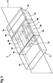
- Figure 3 shows the fuselage 2 of the helicopter 1 of Figure 1 and Figure 2 with the subfloor region 4 of Figure 1 and Figure 2 that accommodates the subfloor arrangement 5 of Figure 2 with the fuel tank arrangement 6 and the cargo hook compartment 7 of Figure 2 .
- the fuselage 2 has a fuselage width FW that is defined by a maximum distance measured orthogonally to a longitudinal mid-plane of the helicopter 1 of Figure 1 and Figure 2 between respective outmost lateral left hand and right hand side fuselage surfaces.
- the fuel tank arrangement 6 now comprises in addition to the front, top and rear fuel tanks 6a, 6b, 6c of Figure 2 at least one and, illustratively, two lateral fuel tanks 6d, wherein the term "lateral” refers to a forward flight direction of the helicopter 1 of Figure 1 and Figure 2 in operation.
- Each one of the lateral fuel tanks 6d is preferably arranged on one side of the cargo hook compartment 7, which is preferentially separated from at least one of the lateral fuel tanks 6d by at least one of the longitudinal frame components 9b of Figure 2 .
- at least one and, preferably, each one of the lateral fuel tanks 6d is separated from the top fuel tank 6b by at least one of the longitudinal frame components 9b.
- Figure 4 shows the subfloor region 4 of the preceding figures that accommodates the subfloor arrangement 5 with the fuel tank arrangement 6 and the cargo hook compartment 7 with the cargo hook arrangement 8 of the preceding figures.
- Figure 4 further illustrates the separation of the front and rear fuel tanks 6a, 6c of the fuel tank arrangement 6 from the cargo hook compartment 7 by means of the transversal frame components 9a of Figure 2 , as well as the separation of the lateral fuel tanks 6d of the fuel tank arrangement 6 from the cargo hook compartment 7 by means of the longitudinal frame components 9b of Figure 3 .
- the transversal and/or longitudinal frame components 9a, 9b are used for carrying the rotation shaft 8a of the cargo hook arrangement 8.
- the latter is rotatably mounted to the longitudinal frame components 9b.
- the cargo hook compartment 7 comprises a length CL that is selected from a range between 0.05 times and 0.8 times of the fuselage width FW of Figure 3 , and preferentially amounts to 0.3 times of this fuselage width FW. Furthermore, the cargo hook compartment 7 comprises a width CW that preferably amounts to 0.3 times of the fuselage width FW, but preferentially at least to less than 0.5 times of its length CL.
- Figure 5 shows the subfloor arrangement 5 with the fuel tank arrangement 6 and the cargo hook compartment 7 of the preceding figures, for further illustrating the embedded arrangement of the cargo hook compartment 7 within the fuel tank arrangement 6. More specifically, Figure 5 clarifies the stacked arrangement of the cargo hook compartment 7 and the top fuel tank 6b of the fuel tank arrangement 6 with respect to a longitudinal mid-plane 10 of the helicopter 1 of Figure 1 and Figure 2 , which illustratively defines a longitudinal symmetry plane of the subfloor arrangement 5.
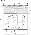
- Figure 6 shows the top fuel tank 6b and the cargo hook compartment 7 of the preceding figures, which are arranged at least partly between the transversal frame components 9a of the preceding figures. More specifically, the top fuel tank 6b and the cargo hook compartment 7 are arranged in stacked manner between the floor structure 3c and the fuselage underside 2a of the fuselage 2 of the preceding figures.
- the floor structure 3c and the fuselage underside 2a are illustratively separated from each other by a distance SH that defines a height of the subfloor region 4 of the preceding figures and is, therefore, hereinafter also referred to as the "subfloor height SH".
- this subfloor height SH is selected from a range between 0.04 times and 0.56 times of the fuselage width FW of Figure 3 .
- the subfloor height SH preferentially amounts to 0.26 times of the fuselage width FW.
- the cargo hook compartment 7 accommodates the cargo hook arrangement 8 of the preceding figures, which is rotatably mounted to the cargo hook compartment 7 by means of the rotation shaft 8a of the preceding figures.
- the latter defines a rotation axis 8b for rotation of the cargo hook arrangement 8 in the cargo hook compartment 7.
- the cargo hook compartment 7 has a height CH, which is preferably greater than a distance AH measured between the rotation axis 8b and the fuselage underside 2a.
- the height CH amounts at least to the difference between the subfloor height SH and a height TH of the top fuel tank 6b. Consequently, by reducing the height CH, the height TH of the top fuel tank 6b can be increased and, thus, a corresponding fuel tank volume thereof.
- the height TH is selected from a range between 0.03 times and 0.9 times of the subfloor height SH, and preferentially amounts to 0.5 times of the subfloor height SH.
- the cargo hook arrangement 8 is shown in a continuous line for illustrating an operation position thereof in an associated operation mode.
- the illustrated operation position corresponds to a stow position associated with the stow mode of the cargo hook arrangement 8, wherein the latter is preferably at least essentially and, exemplarily completely, stowed in the cargo hook compartment 7.
- a lower end of the cargo hook arrangement 8 in the stow position is adjacent to the fuselage underside 2a and spaced apart from this fuselage underside by a predetermined distance ED.
- This distance ED is preferably selected from a range between -0.95 times and 0.35 times of the subfloor height SH, and preferentially amounts to 0.05 times of the subfloor height SH.
- the lower end of the cargo hook arrangement 8 protrudes from the fuselage underside 2a.
- This may e. g. be required if the helicopter 1 of Figure 1 and Figure 2 is retrofitted with a higher loaded, more powerful cargo hook arrangement, which may be larger as the cargo hook arrangement 8, or if the cargo hook arrangement 8 is only integrated partially into the cargo hook compartment 7 in order to merely reduce its aerodynamic effect.
- the higher loaded, more powerful cargo hook arrangement the latter may not submerge entirely into the cargo hook compartment 7 in case of a crash, but nevertheless, this preferably does not affect the preferred configuration and shape of the cargo hook compartment 7, which will consequently not change in shape.
- the cargo hook arrangement 8 is also shown twice in dotted lines for illustrating two different, exemplary crash positions 8', 8" associated with a crash mode of the cargo hook arrangement 8 in the cargo hook compartment 7.
- the cargo hook arrangement 8 is at least forcibly rotatable around the rotation axis 8b defined by the rotation shaft 8a in the cargo hook compartment 7 in a crash load case from the stow position into at least one of the crash positions 8', 8".
- the cargo hook arrangement 8 will initially be rotated in the crash load case from the stow or operation position into one of the crash positions 8', 8", prior to possible subsequent crash measures as described below with reference to Figure 8 .
- Figure 7 shows the cargo hook compartment 7 with the cargo hook arrangement 8 of the preceding figures, which is rotatably mounted to the cargo hook compartment 7 by means of the rotation shaft 8a.
- all side walls that are connected to the outer wall 7a of the cargo hook compartment 7 are defined by the transversal and longitudinal frame components 9a, 9b of the crashworthy frame structure 9a, 9b of the preceding figures.
- separate side walls can be provided.
- the cargo hook arrangement 8 is rotatably mounted to the longitudinal frame components 9b of the crashworthy frame structure 9a, 9b of the preceding figures by means of structural frame attachments 11.
- the latter are preferably mounted to the longitudinal frame components 9b by means of associated fixation means 12, such as screws or rivets.
- rotation shaft 8a respectively the structural frame attachments 11 are only illustratively mounted to the longitudinal frame components 9b. However, they can likewise be mounted to the transversal frame components 9a, as described below with reference to Figure 11 .
- Figure 8 shows the top fuel tank 6b, the two lateral fuel tanks 6d and the cargo hook compartment 7 with the cargo hook arrangement 8 of the preceding figures, as well as the structural frame attachment 11 with the fixation means 12 of Figure 7 .
- the longitudinal frame components 9b and the outer wall 7a of the preceding figures are not shown, for simplicity and clarity of the drawings.
- the top fuel tank 6b is an integral part of at least one of the front and/or rear fuel tanks 6a, 6c.
- the top fuel tank 6b is split into a front part 13a, which is an integral part of its adjacent front fuel tank 6a, and a rear part 13b, which is an integral part of its adjacent rear fuel tank 6c.
- the structural frame attachment 11 is provided with a crash fuse mount 14 that holds the rotation shaft 8a of the cargo hook arrangement 8.
- the rotation shaft 8a and the crash fuse mount 14 are in direct contact with each other so as to permit a predetermined fuse action at least in a crash load case.
- the term "direct contact” means that the crash fuse mount 14 may bearingly contact the rotation shaft 8a or that a comparatively small radial distance may be provided between the crash fuse mount 14 and the rotation shaft 8a that avoids a frictional contact in operation of the cargo hook arrangement 8.
- the crash fuse mount 14 is at least adapted for absorbing energy in the crash load case, which is generated by forces introduced from the rotation shaft 8a into the crash fuse mount 14, as indicated with an arrow 16 that represents an exemplary crash load direction.
- the crash fuse mount 14 is preferentially a separate component which is integrated into the structural frame attachment 11 prior to or after attachment of the latter to the longitudinal frame component 9b.
- the crash fuse mount 14 has two side parts 14a and a center part 14b that interconnects the two side parts 14a.
- Each side part 14a is exemplarily arranged between the rotation shaft 8a of the cargo hook arrangement 8 and one of the lateral fuel tanks 6d
- the center part 14b is exemplarily arranged between the rotation shaft 8a and the top fuel tank 6b.
- the crash fuse mount 14 exemplarily comprises the shape of a returned "U”.
- the crash fuse mount 14 comprises at least one crash fuse element 15 that is provided with predetermined breaking points 15a.
- These predetermined breaking points 15a are preferentially adapted for breaking in the crash load case.
- the crash fuse element 15 comprises a central part 15b and two side parts 15c, which are interconnected by the central part 15b. The corresponding interconnections exemplarily define the predetermined breaking points 15a.
- the crash fuse element 15 is bar-shaped or lath-shaped.
- the central part 15b is accommodated in the center part 14b of the crash fuse mount 14 and each side part 15c is accommodated in a corresponding side part 14a thereof.
- the crash fuse element 15 is a separate component which is integrated into the crash fuse mount 14 prior to or after attachment of the latter to the structural frame attachment 11.
- the center part 14b of the crash fuse mount 14 will be pushed in the direction of the arrow 16 due to the load on the cargo hook arrangement 8.
- the stress of the load will be transferred upon the crash fuse element 15, which comprises the predetermined breaking points 15a that will absorb the occurring crash load energy.
- the crash fuse element 15 will, thus, break as illustrated in Figure 9 and the broken crash fuse parts 15b, 15c will remain in the corresponding parts 14b, 14a of the crash fuse mount 14.
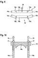
- Figure 9 shows the crash fuse element 15 of Figure 8 with the central part 15b and the two side parts 15c, which define the predetermined breaking points 15a.
- the crash fuse element 15 is shown in its preferred bar-shaped or lath-shaped form of Figure 8 upon occurrence of the crash load case, wherein corresponding forces act on the central part 15b in the direction of the arrow 16 of Figure 8 . These forces lead to a breaking of the crash fuse element 15 at the predetermined breaking points 15a.
- the correspondingly broken crash fuse element is referred to with the reference sign 15'.
- FIG 10 shows the crash fuse mount 14 of Figure 8 , which can be slightly modified according to a variant of the present invention. More specifically, the crash fuse mount 14 can be provided, in contrast to Figure 8 , with crash fuse fixation elements 17 instead of the crash fuse element 15.
- the crash fuse fixation elements 17 are preferably embodied as vertically oriented screws or bolts that are provided in the side parts 14a of the crash fuse mount 14 and adapted to absorb all energy resulting in the crash load case from forces acting on the center part 14b of the crash fuse mount 14 in the direction of the arrow 16 of Figure 8 .
- Figure 11 shows the subfloor region 4 of the preceding figures with the transversal and longitudinal frame components 9a, 9b that accommodates the subfloor arrangement 5 with the fuel tank arrangement 6 and the cargo hook compartment 7 with the cargo hook arrangement 8 of the preceding figures.
- the cargo hook arrangement 8 is now rotatably mounted to the transversal frame components 9a instead of the longitudinal frame components 9b, as described above.
- Figure 12 shows the subfloor region 4 of the preceding figures that accommodates the subfloor arrangement 5 with the cargo hook compartment 7 of the preceding figures.
- the cargo hook compartment 7 now accommodates at least two cargo hook arrangements 8 instead of the single cargo hook arrangement 8, as described above.
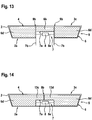
- Figure 13 shows the subfloor region 4 of Figure 3 that accommodates the subfloor arrangement 5 comprising the cargo hook compartment 7 with the cargo hook arrangement 8 of Figure 3 .
- the cargo hook compartment 7 now comprises an access door 7b for closing the cargo hook compartment 7 at least in the above described stow mode, preferably sealingly.
- FIG 14 shows the subfloor region 4 of the preceding figures that accommodates the subfloor arrangement 5 with the cargo hook compartment 7 and the fuel tank arrangement 6 having the top fuel tank 6b and the lateral fuel tanks 6d of the preceding figures.
- the top fuel tank 6b is now an integral part of at least one of the lateral fuel tanks 6d.
- the top fuel tank 6b is split into two lateral parts 13c, 13d, each of which is an integral part of its adjacent lateral fuel tank 6d.
- FIG 15 shows the cargo hook compartment 7 with the cargo hook arrangement 8 having the rotation shaft 8a of Figure 7 .
- the rotation shaft 8a is now rotatably mounted to damping elements 18, which are adapted to absorb all energy that occurs in the crash load case, instead of the structural frame attachments 11 of Figure 7 .
- Each damping element 18 is preferably attached to an adjacent transversal or longitudinal frame component 9a, 9b via suitable attachment means 19, such as screws or rivets.
- the damping elements 18 are preferably adapted to absorb even all energy resulting from very high loads (so-called “shock-loads”). Such shock-load energy may at least partly be transferred by the damping elements 18 via the suitable attachment means 19 to the longitudinal frame components 9a, 9b.
- Figure 16 shows the cargo hook compartment 7 with the cargo hook arrangement 8 of Figure 7 , wherein illustration of the rotation shaft 8a of Figure 7 is omitted for simplicity and clarity of the drawings.
- the cargo hook arrangement 8 is now mounted by means of the attachment means 19 of Figure 15 to the damping element 18 of Figure 15 , which in turn is mounted via the attachment means 19 of Figure 15 to the outer wall 7a of Figure 7 .
- the cargo hook arrangement 8 is generally shown as a simple box and sometimes represented together with the rotation shaft 8a and sometimes without. Sometimes also the rotation shaft 8a is illustrated all alone. However, this is merely done for simplicity and clarity of the drawings, as a detailed configuration of a suitable cargo hook arrangement and a rotatable mounting of such a cargo hook arrangement in general are well-known to the person skilled in the art, so that the schematic representation thereof in the drawings is considered as being sufficient for explaining the preferred realization modes according to the present invention. Otherwise, reference is made to the above-described prior art documents, where these items are described in more detail.
Claims (13)
- Luftfahrzeug (1) mit einem Rumpf (2) und einem Bodenaufbau (3c), der innerhalb des Rumpfes (2) angeordnet ist, wobei der Bodenaufbau (3c) und der Rumpf (2) einen Unterbodenbereich (4) zwischen dem Bodenaufbau (3c) und einer Rumpfunterseite (2a) des Rumpfes (2) definieren, wobei der Unterbodenbereich (4) mindestens eine Hilfskammer (6b) beherbergt, wobei ein Ausrüstungsschacht (7) mit mindestens einer Hilfsausrüstung (8) innerhalb des Unterbodenbereichs (4) angeordnet ist, wobei mindestens eine Hilfsausrüstung (8) mindestens im Wesentlichen in dem Ausrüstungsschacht (7) in einem Verstaumodus verstaubar ist, wobei die mindestens eine Hilfskammer (6b) mindestens teilweise in einem Bereich zwischen dem Ausrüstungsschacht (7) und dem Bodenaufbau (3c) angeordnet ist, derart, dass die mindestens eine Hilfskammer (6b) den Ausrüstungsschacht (7) von dem Bodenaufbau (3c) trennt,dadurch gekennzeichnet, dass die mindestens eine Hilfskammer (6b) als ein Kraftstofftank (6b) ausgeführt ist, und die mindestens eine Hilfsausrüstung (8) in dem Ausrüstungsschacht (7) im Fall einer Kollisionsbelastung gewaltsam von einer Verstauposition, die mit dem Verstaumodus verbunden ist, in mindestens eine Kollisionsposition (8', 8"), die mit einem Kollisionsmodus der mindestens einen Hilfsausrüstung (8) verbunden ist, bewegbar ist,wobei der Unterbodenbereich (4) mit einer kollisionssicheren Rahmenstruktur (9a, 9b) versehen ist, die durch Querrahmenkomponenten (9a) und Längsrahmenkomponenten (9b) definiert ist, wobei die mindestens eine Hilfsausrüstung (8) an vorbestimmten Quer- und/oder Längsrahmenkomponenten (9a, 9b) der kollisionssicheren Rahmenstruktur (9a, 9b) montiert ist,und wobei die mindestens eine Hilfsausrüstung (8) einen Schaft (8a) aufweist, der an den vorbestimmten Quer- und/oder Längsrahmenkomponenten (9a, 9b) der kollisionssicheren Rahmenstruktur (9a, 9b) montiert ist.
- Luftfahrzeug (1) nach Anspruch 1,
dadurch gekennzeichnet, dass der Ausrüstungsschacht (7) mindestens eine Außenwand (7a) aufweist, die die mindestens eine Hilfsausrüstung (8) von der mindestens einen Hilfskammer (6b) trennt. - Luftfahrzeug (1) nach Anspruch 1,
dadurch gekennzeichnet, dass der Schaft (8a) mit Hilfe struktureller Rahmenhalterungen (11) an den vorbestimmten Quer- und/oder Längsrahmenkomponenten (9a, 9b) der kollisionssicheren Rahmenstruktur (9a, 9b) montiert ist. - Luftfahrzeug (1) nach Anspruch 3,
dadurch gekennzeichnet, dass mindestens eine der strukturellen Rahmenhalterungen (11) mit einer Kollisionssicherungshalterung (14) versehen ist, der den Schaft (8a) hält, wobei die Kollisionssicherungshalterung (14) ausgebildet ist, um im Fall einer Kollisionsbelastung Energie zu absorbieren. - Luftfahrzeug (1) nach Anspruch 4,
dadurch gekennzeichnet, dass die Kollisionssicherungshalterung (14) mindestens ein Kollisionssicherungselement (15) aufweist, das mit vorbestimmten Sollbruchstellen (15a) versehen ist, wobei die vorbestimmten Sollbruchstellen (15a) ausgebildet sind, um im Fall einer Kollisionsbelastung zu brechen. - Luftfahrzeug (1) nach Anspruch 5,
dadurch gekennzeichnet, dass die strukturellen Rahmenhalterungen (11) an den vorbestimmten Quer- und/oder Längsrahmenkomponenten (9a, 9b) der kollisionssicheren Rahmenstruktur (9a, 9b) mit Hilfe zugehöriger Befestigungsmittel (12) montiert sind. - Luftfahrzeug (1) nach Anspruch 1,
dadurch gekennzeichnet, dass der Ausrüstungsschacht (7) eine Zugangstür (7b) aufweist, um den Ausrüstungsschacht (7) in dem Verstaumodus zu verschließen, vorzugsweise abdichtend zu verschließen. - Luftfahrzeug (1) nach Anspruch 1,
dadurch gekennzeichnet, dass eine Mehrzahl von Kraftstofftanks (6a, 6c, 6d) um den Ausrüstungsschacht (7) innerhalb des Unterbodenbereichs (4) angeordnet ist. - Luftfahrzeug (1) nach Anspruch 1,
dadurch gekennzeichnet, dass der Ausrüstungsschacht (7) innerhalb des Unterbodenbereichs (4) auf der Seite von mindestens einem seitlichen Kraftstofftank (6d) angeordnet ist, wobei der Kraftstofftank (6b), der durch die mindestens eine Hilfskammer (6b) ausgeführt ist, ein integraler Bestandteil des mindestens einen seitlichen Kraftstofftanks (6d) ist. - Luftfahrzeug (1) nach Anspruch 9,
dadurch gekennzeichnet, dass der Ausrüstungsschacht (7) von dem mindestens einen seitlichen Kraftstofftank (6d) durch mindestens eine Längsrahmenkomponente (9b) getrennt ist. - Luftfahrzeug (1) nach Anspruch 1,
dadurch gekennzeichnet, dass der Ausrüstungsschacht (7) innerhalb des Unterbodenbereichs (4) hinter mindestens einem vorderen Kraftstofftank (6a) und/oder vor mindestens einem hinteren Kraftstofftank (6c) angeordnet ist, wobei der Kraftstofftank (6b), der durch die mindestens eine Hilfskammer (6b) ausgeführt ist, ein integraler Bestandteil des mindestens einen vorderen Kraftstofftanks (6a) und/oder des mindestens einen hinteren Kraftstofftanks (6c) ist. - Luftfahrzeug (1) nach Anspruch 11,
dadurch gekennzeichnet, dass der Ausrüstungsschacht (7) von dem mindestens einen vorderen Kraftstofftank (6a) und/oder von dem mindestens einen hinteren Kraftstofftank (6c) durch mindestens eine Querrahmenkomponente (9a) getrennt ist. - Luftfahrzeug (1) nach Anspruch 1,
dadurch gekennzeichnet, dass die mindestens eine Hilfsausrüstung (8) eine Lasthakenanordnung (8) ist, wobei der Ausrüstungsschacht (7) eine Lasthakenkammer (7) definiert.
Priority Applications (4)
| Application Number | Priority Date | Filing Date | Title |
|---|---|---|---|
| EP15400006.1A EP3053823B1 (de) | 2015-02-06 | 2015-02-06 | Flugzeug mit einem unterbodenabschnitt zur unterbringung eines zusatzfachs |
| EP18169958.8A EP3378757B1 (de) | 2015-02-06 | 2015-02-06 | Flugzeug mit einem unterbodenabschnitt zur unterbringung eines zusatzfachs |
| JP2016004484A JP6246241B2 (ja) | 2015-02-06 | 2016-01-13 | 予備区画を収容するサブフロア領域を備えた航空機 |
| US15/014,090 US9932104B2 (en) | 2015-02-06 | 2016-02-03 | Aircraft with a subfloor region that accommodates an auxiliary compartment |
Applications Claiming Priority (1)
| Application Number | Priority Date | Filing Date | Title |
|---|---|---|---|
| EP15400006.1A EP3053823B1 (de) | 2015-02-06 | 2015-02-06 | Flugzeug mit einem unterbodenabschnitt zur unterbringung eines zusatzfachs |
Related Child Applications (2)
| Application Number | Title | Priority Date | Filing Date |
|---|---|---|---|
| EP18169958.8A Division EP3378757B1 (de) | 2015-02-06 | 2015-02-06 | Flugzeug mit einem unterbodenabschnitt zur unterbringung eines zusatzfachs |
| EP18169958.8A Division-Into EP3378757B1 (de) | 2015-02-06 | 2015-02-06 | Flugzeug mit einem unterbodenabschnitt zur unterbringung eines zusatzfachs |
Publications (2)
| Publication Number | Publication Date |
|---|---|
| EP3053823A1 EP3053823A1 (de) | 2016-08-10 |
| EP3053823B1 true EP3053823B1 (de) | 2018-07-11 |
Family
ID=53180695
Family Applications (2)
| Application Number | Title | Priority Date | Filing Date |
|---|---|---|---|
| EP15400006.1A Active EP3053823B1 (de) | 2015-02-06 | 2015-02-06 | Flugzeug mit einem unterbodenabschnitt zur unterbringung eines zusatzfachs |
| EP18169958.8A Active EP3378757B1 (de) | 2015-02-06 | 2015-02-06 | Flugzeug mit einem unterbodenabschnitt zur unterbringung eines zusatzfachs |
Family Applications After (1)
| Application Number | Title | Priority Date | Filing Date |
|---|---|---|---|
| EP18169958.8A Active EP3378757B1 (de) | 2015-02-06 | 2015-02-06 | Flugzeug mit einem unterbodenabschnitt zur unterbringung eines zusatzfachs |
Country Status (3)
| Country | Link |
|---|---|
| US (1) | US9932104B2 (de) |
| EP (2) | EP3053823B1 (de) |
| JP (1) | JP6246241B2 (de) |
Families Citing this family (8)
| Publication number | Priority date | Publication date | Assignee | Title |
|---|---|---|---|---|
| US10807707B1 (en) * | 2016-09-15 | 2020-10-20 | Draganfly Innovations Inc. | Vertical take-off and landing (VTOL) aircraft having variable center of gravity |
| US10364039B2 (en) * | 2017-04-25 | 2019-07-30 | Bell Helicopter Textron Inc. | Deformable clips for an aircraft fuel systems |
| EP3556655B1 (de) * | 2018-04-17 | 2020-11-18 | AIRBUS HELICOPTERS DEUTSCHLAND GmbH | Vorrichtung zur frachtbeförderung mit einem fluggerät |
| IL260172B (en) | 2018-06-20 | 2021-10-31 | Israel Aerospace Ind Ltd | Aircraft flooring system |
| US11198504B2 (en) * | 2019-04-30 | 2021-12-14 | Textron Innovations Inc. | Energy absorbing landing systems for aircraft |
| GB2598549B (en) * | 2020-08-21 | 2023-06-07 | Hill Group Tech Limited | Mass distribution method and apparatus |
| WO2022038382A1 (en) * | 2020-08-21 | 2022-02-24 | Hill Group Technologies Limited | An improved rotorcraft |
| US11873111B2 (en) * | 2021-01-07 | 2024-01-16 | Textron Innovations Inc. | Fuel cell protection system |
Family Cites Families (32)
| Publication number | Priority date | Publication date | Assignee | Title |
|---|---|---|---|---|
| GB844847A (en) * | 1956-01-23 | 1960-08-17 | English Electric Co Ltd | Improvements in and relating to the fuel system of aircraft |
| US3383078A (en) * | 1964-12-23 | 1968-05-14 | United Aircraft Corp | Auxiliary fluid system |
| US3398934A (en) * | 1966-06-20 | 1968-08-27 | Boeing Co | Cargo winch system |
| US4893767A (en) | 1988-06-24 | 1990-01-16 | United Technologies Corporation | Helicopter cable and equipment guide with shock absorbency |
| US4913380A (en) * | 1988-10-13 | 1990-04-03 | Omac, Inc. | Fuel system for Canard aircraft |
| US5451015A (en) | 1993-05-18 | 1995-09-19 | Bell Helicopter Textron Inc. | Crashworthy composite aircraft structure with integral fuel tank |
| US5582124A (en) * | 1995-07-26 | 1996-12-10 | The United States Of America As Represented By The Secretary Of The Navy | Hybrid framing system for vessels |
| FR2763313B1 (fr) * | 1997-05-14 | 1999-07-16 | Eurocopter France | Dispositif de suspension d'un reservoir d'aeronef |
| US5850991A (en) | 1997-10-02 | 1998-12-22 | Sikorsky Aircraft Corporation | Mechanical emergency dual-release mechanism for an external cargo hook system |
| ES2290162T3 (es) * | 2000-03-10 | 2008-02-16 | Erickson Air-Crane Incorporated | Sistema de carga de fluidos. |
| US6708926B2 (en) * | 2002-05-28 | 2004-03-23 | Sikorsky Aircraft Corporation | Modular integrated self-contained cargo deployment/retrieval system |
| US7357149B2 (en) * | 2004-01-29 | 2008-04-15 | The Boeing Company | Auxiliary fuel tank systems for aircraft and methods for their manufacture and use |
| US7025304B2 (en) * | 2004-04-23 | 2006-04-11 | The United States Of America As Represented By The Secretary Of The Navy | Helicopter messenger cable illumination |
| FR2884802B1 (fr) * | 2005-04-22 | 2008-11-14 | Eurocopter France | Structure porteuse et aeronef a voilure tournante |
| WO2007132454A2 (en) * | 2006-05-11 | 2007-11-22 | Olive Engineering Ltd. | Aircraft with cables to deploy hanging cabin |
| US8376275B2 (en) * | 2006-12-08 | 2013-02-19 | The Boeing Company | Energy absorbing structure for aircraft |
| US7648103B2 (en) * | 2006-12-13 | 2010-01-19 | EMBRAER—Empresa Brasileira de Aeronautica S.A. | Aircraft fuel tanks, systems and methods for increasing an aircraft's on-board fuel capacity |
| US20100187352A1 (en) * | 2007-02-23 | 2010-07-29 | Mr. Michael Yavilevich | Multi deck aircraft |
| FR2933375B1 (fr) * | 2008-07-01 | 2011-04-15 | Airbus France | Agencement de fuselage d'avion |
| FR2933377B1 (fr) * | 2008-07-01 | 2011-04-15 | Airbus France | Avion a train d'atterrissage avant recule |
| FR2936218B1 (fr) * | 2008-09-25 | 2010-10-08 | Airbus France | Structure primaire pour aeronef en materiau composite a tenue au crash amelioree et element structural absorbeur d'energie associe. |
| FR2936491B1 (fr) * | 2008-09-26 | 2010-10-08 | Eurocopter France | Procede de largage d'une charge externe portee par un aeronef et dispositif associe. |
| US20110272523A1 (en) * | 2009-01-19 | 2011-11-10 | Kenji Uegaki | Shock absorption system |
| DE102010014638B4 (de) * | 2010-04-12 | 2019-08-01 | Airbus Defence and Space GmbH | Luftfahrzeug mit einer integrierten energieaufnehmenden Verformungsstruktur und Luftfahrzeug mit einem derartigen Rumpf |
| US9139300B2 (en) | 2010-09-20 | 2015-09-22 | Helimods Pty Ltd. | Load attachment system for helicopters |
| US8532846B2 (en) | 2011-08-26 | 2013-09-10 | Donald John Tollenaere | Helicopter sling-load stability control and release system |
| US8746616B2 (en) * | 2011-10-19 | 2014-06-10 | The Boeing Company | Mid-wing multi-deck airplane |
| FR2992628B1 (fr) * | 2012-06-28 | 2015-03-20 | Airbus Operations Sas | Structure primaire de fuselage pour aeronef comprenant des entretoises a rupture anticipee pour accroitre l'absorption d'energie en cas de crash. |
| US8534608B1 (en) | 2012-09-04 | 2013-09-17 | William Cleveland Cox, IV | Aerial emergency load release mechanism |
| US10800525B2 (en) * | 2013-05-20 | 2020-10-13 | The Boeing Company | Efficient low carbon emission airplane integrating jet fuel and cryogenic fuel systems |
| FR3012791B1 (fr) * | 2013-11-05 | 2015-12-11 | Eurocopter France | Structure de fuselage d'un giravion integrant un plancher median travaillant interpose entre un local habitable et un local technique |
| US9371126B2 (en) * | 2013-12-03 | 2016-06-21 | Airbus Operations Gmbh | Aircraft fuselage |
-
2015
- 2015-02-06 EP EP15400006.1A patent/EP3053823B1/de active Active
- 2015-02-06 EP EP18169958.8A patent/EP3378757B1/de active Active
-
2016
- 2016-01-13 JP JP2016004484A patent/JP6246241B2/ja active Active
- 2016-02-03 US US15/014,090 patent/US9932104B2/en active Active
Non-Patent Citations (1)
| Title |
|---|
| None * |
Also Published As
| Publication number | Publication date |
|---|---|
| EP3378757A1 (de) | 2018-09-26 |
| US20160229516A1 (en) | 2016-08-11 |
| EP3053823A1 (de) | 2016-08-10 |
| JP6246241B2 (ja) | 2017-12-13 |
| US9932104B2 (en) | 2018-04-03 |
| EP3378757B1 (de) | 2019-05-15 |
| JP2016145031A (ja) | 2016-08-12 |
Similar Documents
| Publication | Publication Date | Title |
|---|---|---|
| EP3053823B1 (de) | Flugzeug mit einem unterbodenabschnitt zur unterbringung eines zusatzfachs | |
| US11691722B2 (en) | Multirotor aircraft that is adapted for vertical take-off and landing | |
| EP3702276B1 (de) | Boxwing flugzeug mit mehreren rotoren mit fähigkeit zum senkrechten starten und landen (vtol) | |
| KR100790530B1 (ko) | 기수측 보조 착륙장치, 힘 전달 구조체, 및 회전익 항공기 | |
| RU2392184C2 (ru) | Коммерческий летательный аппарат | |
| KR102009814B1 (ko) | 동체와 집어넣을 수 없는 스키드 타입 랜딩 기어를 갖는 회전익기 | |
| EP3650341B1 (de) | Flugschrauber mit einem starren flügelanordnung | |
| US20030080243A1 (en) | Ground effect airplane | |
| EP2889213A1 (de) | Entenflügler mit Heckbeladung | |
| CA2707092A1 (en) | Impact resistant aircraft fuselage | |
| US20150122939A1 (en) | Rotorcraft having fuel tanks mounted in suspension under a load-bearing middle floor of the fuselage of the rotorcraft | |
| US10486790B2 (en) | Maintenance step for a helicopter | |
| US10589836B2 (en) | Split level forward double deck airliner | |
| US8104717B2 (en) | Air transport with scalloped underbody | |
| EP2840023B1 (de) | Flugzeug mit hinteren Mehrdeckabschnitten mit geteilten Ebenen | |
| EP3263457B1 (de) | Zweistöckiges flugzeug mit geteilten frontebenen | |
| EP3556655A1 (de) | Vorrichtung zur frachtbeförderung mit einem fluggerät | |
| EP4151521A1 (de) | Flugzeug mit einem nach vorne gepfeilten flügel in schulter-flügelkonfiguration | |
| US20240092188A1 (en) | A rotorcraft with an energy source storage unit | |
| RU2243925C2 (ru) | Самолет с топливом, расфасованным в съемные баки | |
| CA2952490C (en) | A maintenance step for a helicopter |
Legal Events
| Date | Code | Title | Description |
|---|---|---|---|
| PUAI | Public reference made under article 153(3) epc to a published international application that has entered the european phase |
Free format text: ORIGINAL CODE: 0009012 |
|
| AK | Designated contracting states |
Kind code of ref document: A1 Designated state(s): AL AT BE BG CH CY CZ DE DK EE ES FI FR GB GR HR HU IE IS IT LI LT LU LV MC MK MT NL NO PL PT RO RS SE SI SK SM TR |
|
| AX | Request for extension of the european patent |
Extension state: BA ME |
|
| 17P | Request for examination filed |
Effective date: 20160718 |
|
| RBV | Designated contracting states (corrected) |
Designated state(s): AL AT BE BG CH CY CZ DE DK EE ES FI FR GB GR HR HU IE IS IT LI LT LU LV MC MK MT NL NO PL PT RO RS SE SI SK SM TR |
|
| STAA | Information on the status of an ep patent application or granted ep patent |
Free format text: STATUS: EXAMINATION IS IN PROGRESS |
|
| 17Q | First examination report despatched |
Effective date: 20161201 |
|
| GRAP | Despatch of communication of intention to grant a patent |
Free format text: ORIGINAL CODE: EPIDOSNIGR1 |
|
| STAA | Information on the status of an ep patent application or granted ep patent |
Free format text: STATUS: GRANT OF PATENT IS INTENDED |
|
| INTG | Intention to grant announced |
Effective date: 20180323 |
|
| GRAJ | Information related to disapproval of communication of intention to grant by the applicant or resumption of examination proceedings by the epo deleted |
Free format text: ORIGINAL CODE: EPIDOSDIGR1 |
|
| STAA | Information on the status of an ep patent application or granted ep patent |
Free format text: STATUS: EXAMINATION IS IN PROGRESS |
|
| GRAR | Information related to intention to grant a patent recorded |
Free format text: ORIGINAL CODE: EPIDOSNIGR71 |
|
| GRAS | Grant fee paid |
Free format text: ORIGINAL CODE: EPIDOSNIGR3 |
|
| STAA | Information on the status of an ep patent application or granted ep patent |
Free format text: STATUS: GRANT OF PATENT IS INTENDED |
|
| GRAA | (expected) grant |
Free format text: ORIGINAL CODE: 0009210 |
|
| STAA | Information on the status of an ep patent application or granted ep patent |
Free format text: STATUS: THE PATENT HAS BEEN GRANTED |
|
| INTC | Intention to grant announced (deleted) | ||
| AK | Designated contracting states |
Kind code of ref document: B1 Designated state(s): AL AT BE BG CH CY CZ DE DK EE ES FI FR GB GR HR HU IE IS IT LI LT LU LV MC MK MT NL NO PL PT RO RS SE SI SK SM TR |
|
| INTG | Intention to grant announced |
Effective date: 20180605 |
|
| REG | Reference to a national code |
Ref country code: GB Ref legal event code: FG4D |
|
| REG | Reference to a national code |
Ref country code: CH Ref legal event code: EP |
|
| REG | Reference to a national code |
Ref country code: AT Ref legal event code: REF Ref document number: 1016608 Country of ref document: AT Kind code of ref document: T Effective date: 20180715 |
|
| REG | Reference to a national code |
Ref country code: IE Ref legal event code: FG4D |
|
| REG | Reference to a national code |
Ref country code: DE Ref legal event code: R096 Ref document number: 602015013353 Country of ref document: DE |
|
| REG | Reference to a national code |
Ref country code: NL Ref legal event code: MP Effective date: 20180711 |
|
| REG | Reference to a national code |
Ref country code: LT Ref legal event code: MG4D |
|
| REG | Reference to a national code |
Ref country code: AT Ref legal event code: MK05 Ref document number: 1016608 Country of ref document: AT Kind code of ref document: T Effective date: 20180711 |
|
| PG25 | Lapsed in a contracting state [announced via postgrant information from national office to epo] |
Ref country code: NL Free format text: LAPSE BECAUSE OF FAILURE TO SUBMIT A TRANSLATION OF THE DESCRIPTION OR TO PAY THE FEE WITHIN THE PRESCRIBED TIME-LIMIT Effective date: 20180711 |
|
| PG25 | Lapsed in a contracting state [announced via postgrant information from national office to epo] |
Ref country code: FI Free format text: LAPSE BECAUSE OF FAILURE TO SUBMIT A TRANSLATION OF THE DESCRIPTION OR TO PAY THE FEE WITHIN THE PRESCRIBED TIME-LIMIT Effective date: 20180711 Ref country code: LT Free format text: LAPSE BECAUSE OF FAILURE TO SUBMIT A TRANSLATION OF THE DESCRIPTION OR TO PAY THE FEE WITHIN THE PRESCRIBED TIME-LIMIT Effective date: 20180711 Ref country code: PL Free format text: LAPSE BECAUSE OF FAILURE TO SUBMIT A TRANSLATION OF THE DESCRIPTION OR TO PAY THE FEE WITHIN THE PRESCRIBED TIME-LIMIT Effective date: 20180711 Ref country code: RS Free format text: LAPSE BECAUSE OF FAILURE TO SUBMIT A TRANSLATION OF THE DESCRIPTION OR TO PAY THE FEE WITHIN THE PRESCRIBED TIME-LIMIT Effective date: 20180711 Ref country code: IS Free format text: LAPSE BECAUSE OF FAILURE TO SUBMIT A TRANSLATION OF THE DESCRIPTION OR TO PAY THE FEE WITHIN THE PRESCRIBED TIME-LIMIT Effective date: 20181111 Ref country code: AT Free format text: LAPSE BECAUSE OF FAILURE TO SUBMIT A TRANSLATION OF THE DESCRIPTION OR TO PAY THE FEE WITHIN THE PRESCRIBED TIME-LIMIT Effective date: 20180711 Ref country code: BG Free format text: LAPSE BECAUSE OF FAILURE TO SUBMIT A TRANSLATION OF THE DESCRIPTION OR TO PAY THE FEE WITHIN THE PRESCRIBED TIME-LIMIT Effective date: 20181011 Ref country code: GR Free format text: LAPSE BECAUSE OF FAILURE TO SUBMIT A TRANSLATION OF THE DESCRIPTION OR TO PAY THE FEE WITHIN THE PRESCRIBED TIME-LIMIT Effective date: 20181012 Ref country code: NO Free format text: LAPSE BECAUSE OF FAILURE TO SUBMIT A TRANSLATION OF THE DESCRIPTION OR TO PAY THE FEE WITHIN THE PRESCRIBED TIME-LIMIT Effective date: 20181011 Ref country code: SE Free format text: LAPSE BECAUSE OF FAILURE TO SUBMIT A TRANSLATION OF THE DESCRIPTION OR TO PAY THE FEE WITHIN THE PRESCRIBED TIME-LIMIT Effective date: 20180711 |
|
| PG25 | Lapsed in a contracting state [announced via postgrant information from national office to epo] |
Ref country code: AL Free format text: LAPSE BECAUSE OF FAILURE TO SUBMIT A TRANSLATION OF THE DESCRIPTION OR TO PAY THE FEE WITHIN THE PRESCRIBED TIME-LIMIT Effective date: 20180711 Ref country code: LV Free format text: LAPSE BECAUSE OF FAILURE TO SUBMIT A TRANSLATION OF THE DESCRIPTION OR TO PAY THE FEE WITHIN THE PRESCRIBED TIME-LIMIT Effective date: 20180711 Ref country code: HR Free format text: LAPSE BECAUSE OF FAILURE TO SUBMIT A TRANSLATION OF THE DESCRIPTION OR TO PAY THE FEE WITHIN THE PRESCRIBED TIME-LIMIT Effective date: 20180711 |
|
| REG | Reference to a national code |
Ref country code: DE Ref legal event code: R097 Ref document number: 602015013353 Country of ref document: DE |
|
| PG25 | Lapsed in a contracting state [announced via postgrant information from national office to epo] |
Ref country code: EE Free format text: LAPSE BECAUSE OF FAILURE TO SUBMIT A TRANSLATION OF THE DESCRIPTION OR TO PAY THE FEE WITHIN THE PRESCRIBED TIME-LIMIT Effective date: 20180711 Ref country code: ES Free format text: LAPSE BECAUSE OF FAILURE TO SUBMIT A TRANSLATION OF THE DESCRIPTION OR TO PAY THE FEE WITHIN THE PRESCRIBED TIME-LIMIT Effective date: 20180711 Ref country code: RO Free format text: LAPSE BECAUSE OF FAILURE TO SUBMIT A TRANSLATION OF THE DESCRIPTION OR TO PAY THE FEE WITHIN THE PRESCRIBED TIME-LIMIT Effective date: 20180711 Ref country code: CZ Free format text: LAPSE BECAUSE OF FAILURE TO SUBMIT A TRANSLATION OF THE DESCRIPTION OR TO PAY THE FEE WITHIN THE PRESCRIBED TIME-LIMIT Effective date: 20180711 |
|
| PLBE | No opposition filed within time limit |
Free format text: ORIGINAL CODE: 0009261 |
|
| STAA | Information on the status of an ep patent application or granted ep patent |
Free format text: STATUS: NO OPPOSITION FILED WITHIN TIME LIMIT |
|
| PG25 | Lapsed in a contracting state [announced via postgrant information from national office to epo] |
Ref country code: DK Free format text: LAPSE BECAUSE OF FAILURE TO SUBMIT A TRANSLATION OF THE DESCRIPTION OR TO PAY THE FEE WITHIN THE PRESCRIBED TIME-LIMIT Effective date: 20180711 Ref country code: SK Free format text: LAPSE BECAUSE OF FAILURE TO SUBMIT A TRANSLATION OF THE DESCRIPTION OR TO PAY THE FEE WITHIN THE PRESCRIBED TIME-LIMIT Effective date: 20180711 Ref country code: SM Free format text: LAPSE BECAUSE OF FAILURE TO SUBMIT A TRANSLATION OF THE DESCRIPTION OR TO PAY THE FEE WITHIN THE PRESCRIBED TIME-LIMIT Effective date: 20180711 |
|
| 26N | No opposition filed |
Effective date: 20190412 |
|
| PG25 | Lapsed in a contracting state [announced via postgrant information from national office to epo] |
Ref country code: SI Free format text: LAPSE BECAUSE OF FAILURE TO SUBMIT A TRANSLATION OF THE DESCRIPTION OR TO PAY THE FEE WITHIN THE PRESCRIBED TIME-LIMIT Effective date: 20180711 |
|
| REG | Reference to a national code |
Ref country code: CH Ref legal event code: PL |
|
| GBPC | Gb: european patent ceased through non-payment of renewal fee |
Effective date: 20190206 |
|
| PG25 | Lapsed in a contracting state [announced via postgrant information from national office to epo] |
Ref country code: LU Free format text: LAPSE BECAUSE OF NON-PAYMENT OF DUE FEES Effective date: 20190206 Ref country code: MC Free format text: LAPSE BECAUSE OF FAILURE TO SUBMIT A TRANSLATION OF THE DESCRIPTION OR TO PAY THE FEE WITHIN THE PRESCRIBED TIME-LIMIT Effective date: 20180711 |
|
| REG | Reference to a national code |
Ref country code: BE Ref legal event code: MM Effective date: 20190228 |
|
| REG | Reference to a national code |
Ref country code: IE Ref legal event code: MM4A |
|
| PG25 | Lapsed in a contracting state [announced via postgrant information from national office to epo] |
Ref country code: LI Free format text: LAPSE BECAUSE OF NON-PAYMENT OF DUE FEES Effective date: 20190228 Ref country code: CH Free format text: LAPSE BECAUSE OF NON-PAYMENT OF DUE FEES Effective date: 20190228 |
|
| PG25 | Lapsed in a contracting state [announced via postgrant information from national office to epo] |
Ref country code: GB Free format text: LAPSE BECAUSE OF NON-PAYMENT OF DUE FEES Effective date: 20190206 Ref country code: IE Free format text: LAPSE BECAUSE OF NON-PAYMENT OF DUE FEES Effective date: 20190206 |
|
| PG25 | Lapsed in a contracting state [announced via postgrant information from national office to epo] |
Ref country code: FR Free format text: LAPSE BECAUSE OF NON-PAYMENT OF DUE FEES Effective date: 20190228 Ref country code: BE Free format text: LAPSE BECAUSE OF NON-PAYMENT OF DUE FEES Effective date: 20190228 |
|
| PG25 | Lapsed in a contracting state [announced via postgrant information from national office to epo] |
Ref country code: TR Free format text: LAPSE BECAUSE OF FAILURE TO SUBMIT A TRANSLATION OF THE DESCRIPTION OR TO PAY THE FEE WITHIN THE PRESCRIBED TIME-LIMIT Effective date: 20180711 |
|
| PG25 | Lapsed in a contracting state [announced via postgrant information from national office to epo] |
Ref country code: MT Free format text: LAPSE BECAUSE OF NON-PAYMENT OF DUE FEES Effective date: 20190206 Ref country code: PT Free format text: LAPSE BECAUSE OF FAILURE TO SUBMIT A TRANSLATION OF THE DESCRIPTION OR TO PAY THE FEE WITHIN THE PRESCRIBED TIME-LIMIT Effective date: 20181111 |
|
| PG25 | Lapsed in a contracting state [announced via postgrant information from national office to epo] |
Ref country code: CY Free format text: LAPSE BECAUSE OF FAILURE TO SUBMIT A TRANSLATION OF THE DESCRIPTION OR TO PAY THE FEE WITHIN THE PRESCRIBED TIME-LIMIT Effective date: 20180711 |
|
| PG25 | Lapsed in a contracting state [announced via postgrant information from national office to epo] |
Ref country code: HU Free format text: LAPSE BECAUSE OF FAILURE TO SUBMIT A TRANSLATION OF THE DESCRIPTION OR TO PAY THE FEE WITHIN THE PRESCRIBED TIME-LIMIT; INVALID AB INITIO Effective date: 20150206 |
|
| PG25 | Lapsed in a contracting state [announced via postgrant information from national office to epo] |
Ref country code: MK Free format text: LAPSE BECAUSE OF FAILURE TO SUBMIT A TRANSLATION OF THE DESCRIPTION OR TO PAY THE FEE WITHIN THE PRESCRIBED TIME-LIMIT Effective date: 20180711 |
|
| PGFP | Annual fee paid to national office [announced via postgrant information from national office to epo] |
Ref country code: IT Payment date: 20230223 Year of fee payment: 9 Ref country code: DE Payment date: 20230216 Year of fee payment: 9 |
|
| P01 | Opt-out of the competence of the unified patent court (upc) registered |
Effective date: 20230530 |
|
| PGFP | Annual fee paid to national office [announced via postgrant information from national office to epo] |
Ref country code: DE Payment date: 20240219 Year of fee payment: 10 |