EP3053779A1 - Vehicular viewing device - Google Patents
Vehicular viewing device Download PDFInfo
- Publication number
- EP3053779A1 EP3053779A1 EP16154202.2A EP16154202A EP3053779A1 EP 3053779 A1 EP3053779 A1 EP 3053779A1 EP 16154202 A EP16154202 A EP 16154202A EP 3053779 A1 EP3053779 A1 EP 3053779A1
- Authority
- EP
- European Patent Office
- Prior art keywords
- pivot
- face
- support
- axis line
- center axis
- Prior art date
- Legal status (The legal status is an assumption and is not a legal conclusion. Google has not performed a legal analysis and makes no representation as to the accuracy of the status listed.)
- Granted
Links
- 238000006073 displacement reaction Methods 0.000 claims abstract description 32
- 230000002093 peripheral effect Effects 0.000 description 25
- 210000000078 claw Anatomy 0.000 description 8
- 239000011347 resin Substances 0.000 description 4
- 229920005989 resin Polymers 0.000 description 4
Images

Classifications
-
- B—PERFORMING OPERATIONS; TRANSPORTING
- B60—VEHICLES IN GENERAL
- B60R—VEHICLES, VEHICLE FITTINGS, OR VEHICLE PARTS, NOT OTHERWISE PROVIDED FOR
- B60R1/00—Optical viewing arrangements; Real-time viewing arrangements for drivers or passengers using optical image capturing systems, e.g. cameras or video systems specially adapted for use in or on vehicles
- B60R1/02—Rear-view mirror arrangements
- B60R1/06—Rear-view mirror arrangements mounted on vehicle exterior
- B60R1/062—Rear-view mirror arrangements mounted on vehicle exterior with remote control for adjusting position
- B60R1/07—Rear-view mirror arrangements mounted on vehicle exterior with remote control for adjusting position by electrically powered actuators
- B60R1/072—Rear-view mirror arrangements mounted on vehicle exterior with remote control for adjusting position by electrically powered actuators for adjusting the mirror relative to its housing
-
- B—PERFORMING OPERATIONS; TRANSPORTING
- B60—VEHICLES IN GENERAL
- B60R—VEHICLES, VEHICLE FITTINGS, OR VEHICLE PARTS, NOT OTHERWISE PROVIDED FOR
- B60R1/00—Optical viewing arrangements; Real-time viewing arrangements for drivers or passengers using optical image capturing systems, e.g. cameras or video systems specially adapted for use in or on vehicles
- B60R1/02—Rear-view mirror arrangements
- B60R1/06—Rear-view mirror arrangements mounted on vehicle exterior
- B60R1/062—Rear-view mirror arrangements mounted on vehicle exterior with remote control for adjusting position
- B60R1/07—Rear-view mirror arrangements mounted on vehicle exterior with remote control for adjusting position by electrically powered actuators
-
- B—PERFORMING OPERATIONS; TRANSPORTING
- B60—VEHICLES IN GENERAL
- B60R—VEHICLES, VEHICLE FITTINGS, OR VEHICLE PARTS, NOT OTHERWISE PROVIDED FOR
- B60R1/00—Optical viewing arrangements; Real-time viewing arrangements for drivers or passengers using optical image capturing systems, e.g. cameras or video systems specially adapted for use in or on vehicles
- B60R1/02—Rear-view mirror arrangements
- B60R1/06—Rear-view mirror arrangements mounted on vehicle exterior
Definitions
- the present invention relates to a vehicular viewing device that aids viewing by a vehicle occupant.
- a spherical face shaped inner peripheral face at a pivot center side of a mirror holder is supported, so as to be capable of pivoting, by a spherical face shaped outer peripheral face at a case inner side.
- a drive rod By displacing a drive rod, the mirror holder and a mirror are pivoted to change a mirror face angle of the mirror.
- the mirror can be pivoted smoothly when the drive rod starts to be displaced.
- an object of the present invention is to obtain a vehicular viewing device in which a viewing means can be pivoted smoothly when a displacement body starts to be displaced.
- a vehicular viewing device of a first aspect of the present invention includes: a support body that is supported at a vehicle body side and that is provided with a support face; a viewing means that is provided, at a pivot center side, with a pivot face supported by the support face so as to be capable of pivoting, and that aids viewing by an occupant of the vehicle; a displacement body that is connected to the viewing means and that is displaced such that the viewing means is pivoted and a viewing direction of the occupant aided by the viewing means is changed; and a limiting cavity that is provided at at least one of the support body or the viewing means, that is disposed at an opposite side from the support face or the pivot face across a center axis line passing through a pivot center of the viewing means parallel to a displacement direction of the displacement body, that has a dimension about the center axis line at least equal to the dimension of the support face or the pivot face, and that limits input from the viewing means to the support body of displacement force of the displacement body.
- the support face is provided at the support body that is supported at the vehicle body side
- the viewing means is provided at the pivot center side with the pivot face that is supported by the support face so as to be capable of pivoting, and the viewing means aids viewing by the vehicle occupant.
- the displacement body is connected to the viewing means, and the displacement body is displaced such that the viewing means is pivoted and the viewing direction of the occupant aided by the viewing means is changed
- the limiting cavity provided at at least one of the support body or the viewing means is disposed at the opposite side from the support face or the pivot face across the center axis line passing through the pivot center of the viewing means parallel to the displacement direction of the displacement body, has the dimension about the center axis line at least equal to the dimension of the support face or the pivot face, and the limiting cavity limits input from the viewing means to the support body of displacement force of the displacement body. This enables the viewing means to be pivoted with respect to the support body, when the displacement body starts to be displaced, and enables the viewing means to be pivoted smoothly.
- a vehicular viewing device of a second aspect of the present invention is the vehicular viewing device of the first aspect of the present invention, wherein the limiting cavity is disposed at a displacement body side of the center axis line, or at an opposite side of the center axis line to the displacement body.
- the limiting cavity is disposed at the displacement body side of the center axis line, or at the opposite side of the center axis line to the displacement body.
- a vehicular viewing device of a third aspect of the present invention is the vehicular viewing device of the first aspect or the second aspect of the present invention, wherein the limiting cavity is a recessed portion.
- the limiting cavity is a recessed portion. This enables the rigidity of the at least one of the support body or the viewing means to be increased, and enables the supporting rigidity of the viewing means by the support body to be increased.
- a vehicular viewing device of a fourth aspect of the present invention is the vehicular viewing device of any one of the first aspect to the third aspect of the present invention, wherein the support body is configured to move.
- the support body is configured to move. This enables the viewing means to be pivoted easily with respect to the support body, when the displacement body is displaced, and enables the pivot action of the viewing means to be stabilized.
- Fig. 1 is a cross-section (a cross-section along line 1-1 in Fig. 2 ) viewed from below, illustrating relevant portions of a vehicle door mirror device 10 according to an exemplary embodiment applied with a vehicle mirror device of the present invention.
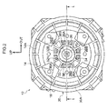
- Fig. 2 is a face-on view viewed from the vehicle rear, illustrating relevant portions of the vehicle door mirror device 10.
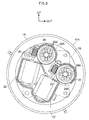
- Fig. 3 is a face-on view viewed from the vehicle rear, illustrating some of the relevant portions of the vehicle door mirror device 10. Note that in the drawings, the arrow FR indicates the vehicle front, the arrow WO indicates the vehicle width direction outside, and the arrow UP indicates upward.
- the vehicle door mirror device 10 is installed at the outside of a door (side door) of a vehicle, and a mirror face adjustment device 12, serving as a changing means, is provided at the interior of the vehicle door mirror device 10.
- the mirror face adjustment device 12 includes a substantially semispherical container shaped case 14, made from resin and serving as an outer peripheral support body, and the case 14 is fixed to the interior of the vehicle door mirror device 10.
- a vehicle rear side face of the case 14 is open in a circular shape
- a bottom wall (vehicle front side wall) of the case 14 has a circular flat plate shape
- a peripheral wall 14A (outer peripheral support portion) of the case 14 is curved in a spherical wall shape.
- the vehicle rear side face (opening), the bottom wall, and the peripheral wall 14A of the case 14 are disposed coaxially to a center axis line L (see Fig. 1 ) parallel to the vehicle front-rear direction, this being the center axis line of the case 14.
- the peripheral wall 14A of the case 14 curves centered on a pivot center O (see Fig. 1 ) on the center axis line L.
- a container shaped case inner 16 made from resin and serving as an outer support body, is fixed to the bottom wall inside the case 14, and a vehicle front side face of the case inner 16 is open.
- a circular tube shaped fixing tube 18 is integrally provided at a bottom wall (vehicle rear side wall) of the case inner 16. The fixing tube 18 projects out toward the vehicle rear side, and is disposed coaxially to the center axis line L.
- a substantially circular tube shaped support wall 20, serving as an outer support section, is integrally provided at the bottom wall of the case inner 16 at the outer peripheral side of the fixing tube 18.
- the support wall 20 projects out toward the vehicle rear side, and is disposed coaxially to the center axis line L.
- An inner peripheral face of a vehicle rear side portion of the support wall 20 configures a spherical face shaped outer support face 20A, and the outer support face 20A is curved in a recessed shape centered on the pivot center O.
- a pair of motors 22, serving as drive means, are provided inside the case 14, and the motors 22 are fixed between the bottom wall of the case 14 and the bottom wall of the case inner 16.
- a worm 24 is fixed to an output shaft of each motor 22.
- a pair of substantially circular tube shaped wheel drives 26, serving as engagement members, are provided inside the case 14.
- Each wheel drive 26 is supported between the bottom wall of the case 14 and the bottom wall of the case inner 16 so as to be capable of rotating about its axis.
- the inside of each wheel drive 26 is open toward the vehicle rear side of the case inner 16 through the bottom wall of the case inner 16.
- a worm wheel 26A is formed to each wheel drive 26, and the worm 24 of the respective motor 22 is meshed (engaged) with the worm wheel 26A.
- the motors 22 to rotate the worms 24
- the worm wheels 26A are rotated to rotate the wheel drives 26.
- a specific number (four in the present exemplary embodiment) of meshing claws 26B, serving as engagement portions, are provided at each wheel drive 26.
- the specific number of meshing claws 26B are disposed at equal spacings around the circumferential direction of the wheel drive 26.
- the meshing claws 26B extend out from the wheel drive 26 toward the vehicle rear side, and have elasticity.
- a leading end (vehicle rear side end) of each meshing claw 26B projects out toward the radial direction inside of the wheel drive 26.
- a substantially circular column shaped drive rod 28, serving as a displacement body, is coaxially inserted inside each wheel drive 26.
- the drive rod 28 projects out from the case inner 16 toward the vehicle rear side, and rotation about its axis is restricted.
- One of the drive rods 28 is disposed with its axial direction parallel to the center axis line L above (or below) the center axis line L, and the other drive rod 28 is disposed with its axial direction parallel to the center axis line L at the vehicle width direction outside (or at the vehicle width direction inside) of the center axis line L.
- a portion of the drive rod 28 other than a leading end portion configures a thread 28A, and the leading ends of the meshing claws 26B of the respective wheel drive 26 are meshed (engaged) with the thread 28A.
- a meshed position of the leading ends of the meshing claws 26B with the thread 28A is changed, such that the drive rod 28 is displaced along the vehicle front-rear direction (axial direction).
- a resin mirror holder 30 with a bottomed, substantially circular tube shape, serving as a pivot member configuring a viewing means, is provided at the vehicle rear side of the case 14.
- the mirror holder 30 is disposed coaxially to the center axis line L.
- a vehicle front side face of the mirror holder 30 is open in a circular shape
- a bottom wall (vehicle rear side end wall) of the mirror holder 30 has a substantially circular flat plate shape
- a peripheral wall 30A (outer peripheral pivot section) of the mirror holder 30 is curved in a spherical wall shape centered on the pivot center O.
- the peripheral wall 30A of the mirror holder 30 is disposed at the inner peripheral side of the peripheral wall 14A of the case 14, and the peripheral wall 30A of the mirror holder 30 is supported by the peripheral wall 14A of the case 14.
- a substantially circular tube shaped inner wall 32 serving as a pivot section (inner peripheral pivot section), is integrally provided at a center portion of the bottom wall of the mirror holder 30.
- the inside of the inner wall 32 is open toward the vehicle front side and the vehicle rear side.
- the inner wall 32 is curved in a spherical wall shape centered on the pivot center O, and the inner wall 32 is disposed at the inner peripheral side of the support wall 20 of the case inner 16.
- An outer peripheral face of the inner wall 32 configures a spherical face shaped outer pivot face 32A
- an inner peripheral face of the inner wall 32 configures a spherical face shaped inner pivot face 32B, serving as a pivot face.
- the outer pivot face 32A is supported by (is in face-to-face contact with) the outer support face 20A of the support wall 20.
- the fixing tube 18 of the case inner 16 coaxially penetrates the inside of the support pivot 34, and the support pivot 34 is disposed coaxially to the center axis line L.
- a portion of the support pivot 34 other than a vehicle front side end configures an inner support section 36, serving as a support section.
- the inner support section 36 is disposed coaxially to the center axis line L, and its outer diameter gradually increases on progression toward the vehicle rear.
- Three inner support faces 36A are formed to an outer peripheral face of the inner support section 36.
- the three inner support faces 36A respectively extend across the entire axial-circumferential direction of the inner support section 36, this being centered on the pivot center O and passing through the center axis line L, and are disposed at equal spacings centered on the center axis line L.
- the inner support faces 36A are each curved in a spherical face shape centered on the pivot center O, and the inner supporting faces 36A are in face-to-face contact with the inner pivot face 32B of the inner wall 32 of the mirror holder 30, and support the inner pivot face 32B.
- Limiting recessed portions 36B serving as limiting cavities, are formed to the outer peripheral face of the inner support section 36 between the inner support faces 36A about the center axis line L.
- the limiting recessed portions 36B are open from a vehicle rear side end of the inner support section 36, and, at the vehicle rear side end (maximum diameter portion) of the inner support section 36, each has a dimension about the center axis line L that is larger than that of the respective inner support face 36A.
- the limiting recessed portions 36B are disposed across the center axis line L on opposite sides to the respective inner support faces 36A.
- One of the inner support faces 36A is disposed at the other (the vehicle width direction outside) drive rod 28 side of the center axis line L, and the corresponding limiting recessed portion 36B is disposed at the opposite side of the center axis line L to the other drive rod 28.
- a thread portion 38A of a screw 38, configuring an attachment means is coaxially screwed inside the fixing tube 18 of the case inner 16.
- the thread portion 38A of the screw 38 also coaxially penetrates inside a circular ring flat plate shaped washer 40, configuring the attachment means, and the washer 40 is clamped between the fixing tube 18 and a head portion 38B of the screw 38.
- a coil spring 42 serving as a biasing means (movement means), spans across between the washer 40 and a bottom wall (vehicle front side wall) of the support pivot 34. The coil spring 42 is compressed, and biases the support pivot 34 toward the vehicle front side.
- the inner wall 32 of the mirror holder 30 is clamped between the outer support face 20A of the support wall 20 of the case inner 16 and the inner support faces 36A of the inner support section 36 of the support pivot 34, and the peripheral wall 30A of the mirror holder 30 is press-contacted to the peripheral wall 14A of the case 14, attaching the mirror holder 30 to the case 14 and to the case inner 16.
- the support pivot 34 is configured to move toward the vehicle rear side against the biasing force of the coil spring 42.
- the bottom wall (vehicle rear side wall) of the mirror holder 30 retains the leading end portion (vehicle rear side end portion) of each drive rod 28 so as to be capable of pivoting.
- each motor 22 By driving each motor 22 to displace the respective drive rod 28 along the vehicle front-rear direction as described above, the mirror holder 30 is pivoted about the pivot center O.
- a mirror 44 serving as a main body section configuring the viewing means, is fitted so as to be capable of being attached and detached to the vehicle rear side of the bottom wall of the mirror holder 30.
- the mirror 44 is capable of pivoting integrally with the mirror holder 30.
- a mirror face 44A (the surface of a reflective layer at a back side) of the mirror 44 faces the vehicle rear side, and the mirror 44 is capable of aiding viewing of the vehicle rear side by a vehicle occupant.
- the wheel drive 26 (including the worm wheel 26A and the specific number of meshing claws 26B) is rotated to displace the drive rod 28 along the vehicle front-rear direction.
- the wheel drive 26 including the worm wheel 26A and the specific number of meshing claws 26B
- an angle of the mirror face 44A of the mirror 44 is adjusted in at least the one direction of the up-down direction and the vehicle width direction (the viewing direction of the occupant aided by the mirror 44 is changed).
- the limiting recessed portions 36B of the inner support section 36 of the support pivot 34 are each disposed across the center axis line L at the opposite side from the respective inner support face 36A, and, at the vehicle rear side end of the inner support section 36, each has a larger dimension about the center axis line L than that of the inner support faces 36A. Input from the mirror holder 30 (inner wall 32) to the support pivot 34 (inner support section 36) of displacement force of the drive rods 28 toward the vehicle rear is thereby limited by the limiting recessed portions 36B (portions around the center axis line L).
- the mirror holder 30 can be suppressed from moving, against the biasing force of the coil spring 42, toward the vehicle rear side integrally with the support pivot 34 in a state in which the displacement force of the drive rod 28 is input from the mirror holder 30 (inner wall 32) to the support pivot 34 (inner support section 36) around the entire center axis line L such that the mirror holder 30 (inner wall 32) does not pivot with respect to the support pivot 34 (inner support section 36).
- one of the limiting recessed portions 36B is disposed across the center axis line L at the opposite side from the other (vehicle width direction outside) drive rod 28.
- This enables the input from the mirror holder 30 (inner wall 32) to the support pivot 34 (inner support section 36) of displacement force of the other drive rod 28 toward the vehicle rear to be effectively limited by this limiting recessed portion 36B.
- This thereby enables the mirror holder 30 (inner wall 32) to be pivoted effectively with respect to the support pivot 34 (inner support section 36) when the other drive rod 28 starts to be displaced toward the vehicle rear, and enables the mirror holder 30 and the mirror 44 to be pivoted even more smoothly.
- the support pivot 34 is configured to move toward the vehicle rear side against the biasing force of the coil spring 42.
- the limiting recessed portions 36B are each formed in a recessed shape that does not penetrate the peripheral wall of the inner support section 36 of the support pivot 34. This enables the rigidity of the inner support section 36 to be increased, enables the supporting rigidity of the mirror holder 30 (inner wall 32) and the mirror 44 by the support pivot 34 (inner support section 36) to be increased, enables the mirror face 44A of the mirror 44 to be suppressed from shaking while the vehicle is travelling, and so on.
- one of the limiting recessed portions 36B is disposed across the center axis line L at the opposite side from the other (vehicle width direction outside) drive rod 28.
- one of the limiting recessed portions 36B may be disposed at the other drive rod 28 side of the center axis line L.
- One of the limiting recessed portions 36B may also be disposed across the center axis line L at the one (upper side) drive rod 28 side of the center axis line L, or at the opposite side from the one drive rod 28 side.
- the maximum dimension of each of the limiting recessed portions 36B about the center axis line L is larger than that of the inner support faces 36A. However, it is sufficient that the maximum dimension of each of the limiting recessed portions 36B about the center axis line L is at least that of the inner support faces 36A.
- the inner support faces 36A of the support pivot 34 extend in a axial-circumferential direction, which is centered on the pivot center O and passes through the center axis line L.
- the inner support faces 36A of the support pivot 34 may be inclined in a direction that progresses around the center axis line L on progression along the axial-circumferential direction, which is centered on the pivot center O and passes through the center axis line L.
- three inner support faces 36A and three limiting recessed portions 36B are respectively provided at the support pivot 34 (inner support section 36).
- one or two inner support faces 36A and one or two limiting recessed portions 36B may be respectively provided at the support pivot 34 (inner support section 36).
- four or more inner support faces 36A and four or more limiting recessed portions 36B may be respectively provided at the support pivot 34 (inner support section 36).
- the inner support faces 36A are provided at the inner support section 36 of the support pivot 34 across the entire axial-circumferential direction, which is centered on the pivot center O and passes through the center axis line L.
- inner support faces 36A may be provided at a portion (such as only an intermediate portion) of the inner support section 36 of the support pivot 34, a portion along the axial-circumferential direction centered on the pivot center O and passing through the center axis line L, and limiting recessed portions 36B may be provided at the axial-circumferential direction ends of the inner support faces 36A.
- the limiting cavities of the present invention are the limiting recessed portions 36B.
- the limiting cavities of the present invention may be through-holes.
- the limiting recessed portions 36B are provided at the inner support section 36 of the support pivot 34.
- limiting recessed portions 36B may be provided at the inner pivot face 32B side of the inner wall 32 of the mirror holder 30.
- the vehicle door mirror device 10 is a vehicular viewing device of the present invention.
- a vehicular viewing device of the present invention may be another vehicle mirror device at the vehicle exterior or vehicle interior, or may be a vehicle camera device that aids viewing by a vehicle occupant using captured images.
- an inner wall of a mirror holder is supported by an inner support face of an inner support section of a support pivot, and a drive rod is displaced to pivot the mirror holder and a mirror.
- a limiting recessed portion of the inner support section is disposed across a center axis line at the opposite side from the inner support face, and has a larger dimension about the center axis line than that of the inner support face. Input from the inner wall to the inner support section of displacement force of the drive rod toward the vehicle rear is limited by the limiting recessed portion.
Landscapes
- Engineering & Computer Science (AREA)
- Multimedia (AREA)
- Mechanical Engineering (AREA)
- Rear-View Mirror Devices That Are Mounted On The Exterior Of The Vehicle (AREA)
Abstract
Description
- The present invention relates to a vehicular viewing device that aids viewing by a vehicle occupant.
- In a vehicle door mirror device described in Japanese Patent Application Laid-Open (
JP-A) No. 2013-163498 - Note that, in such vehicle door mirror devices, it is preferable that the mirror can be pivoted smoothly when the drive rod starts to be displaced.
- In consideration of the above circumstances, an object of the present invention is to obtain a vehicular viewing device in which a viewing means can be pivoted smoothly when a displacement body starts to be displaced.
- A vehicular viewing device of a first aspect of the present invention includes: a support body that is supported at a vehicle body side and that is provided with a support face; a viewing means that is provided, at a pivot center side, with a pivot face supported by the support face so as to be capable of pivoting, and that aids viewing by an occupant of the vehicle; a displacement body that is connected to the viewing means and that is displaced such that the viewing means is pivoted and a viewing direction of the occupant aided by the viewing means is changed; and a limiting cavity that is provided at at least one of the support body or the viewing means, that is disposed at an opposite side from the support face or the pivot face across a center axis line passing through a pivot center of the viewing means parallel to a displacement direction of the displacement body, that has a dimension about the center axis line at least equal to the dimension of the support face or the pivot face, and that limits input from the viewing means to the support body of displacement force of the displacement body.
- In the vehicular viewing device of the first aspect of the present invention, the support face is provided at the support body that is supported at the vehicle body side, the viewing means is provided at the pivot center side with the pivot face that is supported by the support face so as to be capable of pivoting, and the viewing means aids viewing by the vehicle occupant. The displacement body is connected to the viewing means, and the displacement body is displaced such that the viewing means is pivoted and the viewing direction of the occupant aided by the viewing means is changed
- Note that the limiting cavity provided at at least one of the support body or the viewing means is disposed at the opposite side from the support face or the pivot face across the center axis line passing through the pivot center of the viewing means parallel to the displacement direction of the displacement body, has the dimension about the center axis line at least equal to the dimension of the support face or the pivot face, and the limiting cavity limits input from the viewing means to the support body of displacement force of the displacement body. This enables the viewing means to be pivoted with respect to the support body, when the displacement body starts to be displaced, and enables the viewing means to be pivoted smoothly.
- A vehicular viewing device of a second aspect of the present invention is the vehicular viewing device of the first aspect of the present invention, wherein the limiting cavity is disposed at a displacement body side of the center axis line, or at an opposite side of the center axis line to the displacement body.
- In the vehicular viewing device of the second aspect of the present invention, the limiting cavity is disposed at the displacement body side of the center axis line, or at the opposite side of the center axis line to the displacement body. This enables the viewing means to be effectively pivoted with respect to the support body, when the displacement body starts to be displaced, and enables the viewing means to be pivoted more smoothly.
- A vehicular viewing device of a third aspect of the present invention is the vehicular viewing device of the first aspect or the second aspect of the present invention, wherein the limiting cavity is a recessed portion.
- In the vehicular viewing device of the third aspect of the present invention, the limiting cavity is a recessed portion. This enables the rigidity of the at least one of the support body or the viewing means to be increased, and enables the supporting rigidity of the viewing means by the support body to be increased.
- A vehicular viewing device of a fourth aspect of the present invention is the vehicular viewing device of any one of the first aspect to the third aspect of the present invention, wherein the support body is configured to move.
- In the vehicular viewing device of the fourth aspect of the present invention, the support body is configured to move. This enables the viewing means to be pivoted easily with respect to the support body, when the displacement body is displaced, and enables the pivot action of the viewing means to be stabilized.
- Exemplary embodiments of the present invention will be described in detail based on the following figures, wherein:
-
Fig. 1 is a cross-section (a cross-section along line 1-1 inFig. 2 ) viewed from below, illustrating a mirror face adjustment device of a vehicle door mirror device according to an exemplary embodiment of the present invention; -
Fig. 2 is a face-on view viewed from the vehicle rear, illustrating the mirror face adjustment device of the vehicle door mirror device according to the exemplary embodiment of the present invention; -
Fig. 3 is a face-on view viewed from the vehicle rear, illustrating a case, and so on of the mirror face adjustment device of the vehicle door mirror device according to the exemplary embodiment of the present invention; -
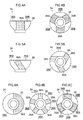
Fig. 4A is a side view illustrating a support pivot of the mirror face adjustment device of the vehicle door mirror device according to the exemplary embodiment of the present invention; -
Fig. 4B is a lower face view illustrating the support pivot of the mirror face adjustment device of the vehicle door mirror device according to the exemplary embodiment of the present invention; -
Fig. 5A is a side view illustrating a first modified example of a support pivot of the mirror face adjustment device of the vehicle door mirror device according to the exemplary embodiment of the present invention; -
Fig. 5B is a lower face view illustrating the first modified example of the support pivot of the mirror face adjustment device of the vehicle door mirror device according to the exemplary embodiment of the present invention; -
Fig. 6A is a lower face view illustrating a second modified example of a support pivot of the mirror face adjustment device of the vehicle door mirror device according to the exemplary embodiment of the present invention; -
Fig. 6B is a lower face view illustrating a third modified example of a support pivot of the mirror face adjustment device of the vehicle door mirror device according to the exemplary embodiment of the present invention; and -
Fig. 6C is a lower face view illustrating a fourth modified example of a support pivot of the mirror face adjustment device of the vehicle door mirror device according to the exemplary embodiment of the present invention. -
Fig. 1 is a cross-section (a cross-section along line 1-1 inFig. 2 ) viewed from below, illustrating relevant portions of a vehicledoor mirror device 10 according to an exemplary embodiment applied with a vehicle mirror device of the present invention.Fig. 2 is a face-on view viewed from the vehicle rear, illustrating relevant portions of the vehicledoor mirror device 10.Fig. 3 is a face-on view viewed from the vehicle rear, illustrating some of the relevant portions of the vehicledoor mirror device 10. Note that in the drawings, the arrow FR indicates the vehicle front, the arrow WO indicates the vehicle width direction outside, and the arrow UP indicates upward. - The vehicle
door mirror device 10 according to the present exemplary embodiment is installed at the outside of a door (side door) of a vehicle, and a mirrorface adjustment device 12, serving as a changing means, is provided at the interior of the vehicledoor mirror device 10. - As illustrated in
Fig. 1 to Fig. 3 , the mirrorface adjustment device 12 includes a substantially semispherical container shapedcase 14, made from resin and serving as an outer peripheral support body, and thecase 14 is fixed to the interior of the vehicledoor mirror device 10. A vehicle rear side face of thecase 14 is open in a circular shape, a bottom wall (vehicle front side wall) of thecase 14 has a circular flat plate shape, and aperipheral wall 14A (outer peripheral support portion) of thecase 14 is curved in a spherical wall shape. The vehicle rear side face (opening), the bottom wall, and theperipheral wall 14A of thecase 14 are disposed coaxially to a center axis line L (seeFig. 1 ) parallel to the vehicle front-rear direction, this being the center axis line of thecase 14. Theperipheral wall 14A of thecase 14 curves centered on a pivot center O (seeFig. 1 ) on the center axis line L. - A container shaped case inner 16, made from resin and serving as an outer support body, is fixed to the bottom wall inside the
case 14, and a vehicle front side face of the case inner 16 is open. A circular tube shapedfixing tube 18 is integrally provided at a bottom wall (vehicle rear side wall) of the case inner 16. Thefixing tube 18 projects out toward the vehicle rear side, and is disposed coaxially to the center axis line L. - A substantially circular tube shaped
support wall 20, serving as an outer support section, is integrally provided at the bottom wall of the case inner 16 at the outer peripheral side of thefixing tube 18. Thesupport wall 20 projects out toward the vehicle rear side, and is disposed coaxially to the center axis line L. An inner peripheral face of a vehicle rear side portion of thesupport wall 20 configures a spherical face shapedouter support face 20A, and theouter support face 20A is curved in a recessed shape centered on the pivot center O. - A pair of
motors 22, serving as drive means, are provided inside thecase 14, and themotors 22 are fixed between the bottom wall of thecase 14 and the bottom wall of the case inner 16. Aworm 24 is fixed to an output shaft of eachmotor 22. - A pair of substantially circular tube shaped
wheel drives 26, serving as engagement members, are provided inside thecase 14. Eachwheel drive 26 is supported between the bottom wall of thecase 14 and the bottom wall of the case inner 16 so as to be capable of rotating about its axis. The inside of eachwheel drive 26 is open toward the vehicle rear side of the case inner 16 through the bottom wall of the case inner 16. - A
worm wheel 26A is formed to eachwheel drive 26, and theworm 24 of therespective motor 22 is meshed (engaged) with theworm wheel 26A. Thus, by driving themotors 22 to rotate theworms 24, theworm wheels 26A are rotated to rotate thewheel drives 26. - A specific number (four in the present exemplary embodiment) of meshing
claws 26B, serving as engagement portions, are provided at eachwheel drive 26. The specific number of meshingclaws 26B are disposed at equal spacings around the circumferential direction of thewheel drive 26. The meshingclaws 26B extend out from thewheel drive 26 toward the vehicle rear side, and have elasticity. A leading end (vehicle rear side end) of each meshingclaw 26B projects out toward the radial direction inside of thewheel drive 26. - A substantially circular column shaped
drive rod 28, serving as a displacement body, is coaxially inserted inside eachwheel drive 26. Thedrive rod 28 projects out from the case inner 16 toward the vehicle rear side, and rotation about its axis is restricted. One of thedrive rods 28 is disposed with its axial direction parallel to the center axis line L above (or below) the center axis line L, and theother drive rod 28 is disposed with its axial direction parallel to the center axis line L at the vehicle width direction outside (or at the vehicle width direction inside) of the center axis line L. - A portion of the
drive rod 28 other than a leading end portion (vehicle rear side end portion) configures athread 28A, and the leading ends of the meshingclaws 26B of the respective wheel drive 26 are meshed (engaged) with thethread 28A. Thus, by rotating each wheel drive 26 (including the meshingclaws 26B) as described above, a meshed position of the leading ends of the meshingclaws 26B with thethread 28A is changed, such that thedrive rod 28 is displaced along the vehicle front-rear direction (axial direction). - A
resin mirror holder 30 with a bottomed, substantially circular tube shape, serving as a pivot member configuring a viewing means, is provided at the vehicle rear side of thecase 14. Themirror holder 30 is disposed coaxially to the center axis line L. A vehicle front side face of themirror holder 30 is open in a circular shape, a bottom wall (vehicle rear side end wall) of themirror holder 30 has a substantially circular flat plate shape, and aperipheral wall 30A (outer peripheral pivot section) of themirror holder 30 is curved in a spherical wall shape centered on the pivot center O. Theperipheral wall 30A of themirror holder 30 is disposed at the inner peripheral side of theperipheral wall 14A of thecase 14, and theperipheral wall 30A of themirror holder 30 is supported by theperipheral wall 14A of thecase 14. - A substantially circular tube shaped
inner wall 32, serving as a pivot section (inner peripheral pivot section), is integrally provided at a center portion of the bottom wall of themirror holder 30. The inside of theinner wall 32 is open toward the vehicle front side and the vehicle rear side. Theinner wall 32 is curved in a spherical wall shape centered on the pivot center O, and theinner wall 32 is disposed at the inner peripheral side of thesupport wall 20 of the case inner 16. An outer peripheral face of theinner wall 32 configures a spherical face shaped outer pivot face 32A, and an inner peripheral face of theinner wall 32 configures a spherical face shapedinner pivot face 32B, serving as a pivot face. The outer pivot face 32A is supported by (is in face-to-face contact with) theouter support face 20A of thesupport wall 20. - A
resin support pivot 34 with a bottomed, substantially circular tube shape, serving as a support body (inner support body), is provided inside theinner wall 32, and the inside of thesupport pivot 34 is open toward the vehicle rear side. The fixingtube 18 of the case inner 16 coaxially penetrates the inside of thesupport pivot 34, and thesupport pivot 34 is disposed coaxially to the center axis line L. - As illustrated in
Fig. 4A and Fig. 4B , a portion of thesupport pivot 34 other than a vehicle front side end configures aninner support section 36, serving as a support section. Theinner support section 36 is disposed coaxially to the center axis line L, and its outer diameter gradually increases on progression toward the vehicle rear. - Three inner support faces 36A, each serving as a support face, are formed to an outer peripheral face of the
inner support section 36. The three inner support faces 36A respectively extend across the entire axial-circumferential direction of theinner support section 36, this being centered on the pivot center O and passing through the center axis line L, and are disposed at equal spacings centered on the center axis line L. The inner support faces 36A are each curved in a spherical face shape centered on the pivot center O, and the inner supporting faces 36A are in face-to-face contact with theinner pivot face 32B of theinner wall 32 of themirror holder 30, and support theinner pivot face 32B. - Limiting recessed
portions 36B, serving as limiting cavities, are formed to the outer peripheral face of theinner support section 36 between the inner support faces 36A about the center axis line L. The limiting recessedportions 36B are open from a vehicle rear side end of theinner support section 36, and, at the vehicle rear side end (maximum diameter portion) of theinner support section 36, each has a dimension about the center axis line L that is larger than that of the respectiveinner support face 36A. The limiting recessedportions 36B are disposed across the center axis line L on opposite sides to the respective inner support faces 36A. One of the inner support faces 36A is disposed at the other (the vehicle width direction outside) driverod 28 side of the center axis line L, and the corresponding limiting recessedportion 36B is disposed at the opposite side of the center axis line L to theother drive rod 28. - As illustrated in
Fig. 1 , athread portion 38A of ascrew 38, configuring an attachment means, is coaxially screwed inside the fixingtube 18 of the case inner 16. Thethread portion 38A of thescrew 38 also coaxially penetrates inside a circular ring flat plate shapedwasher 40, configuring the attachment means, and thewasher 40 is clamped between the fixingtube 18 and ahead portion 38B of thescrew 38. Acoil spring 42, serving as a biasing means (movement means), spans across between thewasher 40 and a bottom wall (vehicle front side wall) of thesupport pivot 34. Thecoil spring 42 is compressed, and biases thesupport pivot 34 toward the vehicle front side. Thus, due to the biasing force of thecoil spring 42, theinner wall 32 of themirror holder 30 is clamped between theouter support face 20A of thesupport wall 20 of the case inner 16 and the inner support faces 36A of theinner support section 36 of thesupport pivot 34, and theperipheral wall 30A of themirror holder 30 is press-contacted to theperipheral wall 14A of thecase 14, attaching themirror holder 30 to thecase 14 and to the case inner 16. Thesupport pivot 34 is configured to move toward the vehicle rear side against the biasing force of thecoil spring 42. - The bottom wall (vehicle rear side wall) of the
mirror holder 30 retains the leading end portion (vehicle rear side end portion) of eachdrive rod 28 so as to be capable of pivoting. By driving eachmotor 22 to displace therespective drive rod 28 along the vehicle front-rear direction as described above, themirror holder 30 is pivoted about the pivot center O. - A
mirror 44, serving as a main body section configuring the viewing means, is fitted so as to be capable of being attached and detached to the vehicle rear side of the bottom wall of themirror holder 30. Themirror 44 is capable of pivoting integrally with themirror holder 30. Amirror face 44A (the surface of a reflective layer at a back side) of themirror 44 faces the vehicle rear side, and themirror 44 is capable of aiding viewing of the vehicle rear side by a vehicle occupant. - Explanation follows regarding operation of the present exemplary embodiment.
- In the mirror
face adjustment device 12 of the vehicledoor mirror device 10 with the above configuration, by driving eachmotor 22 to rotate theworm 24, the wheel drive 26 (including theworm wheel 26A and the specific number of meshingclaws 26B) is rotated to displace thedrive rod 28 along the vehicle front-rear direction. Thus, by pivoting themirror holder 30 and themirror 44 in at least one direction of the up-down direction and the vehicle width direction using thedrive rods 28, an angle of themirror face 44A of themirror 44 is adjusted in at least the one direction of the up-down direction and the vehicle width direction (the viewing direction of the occupant aided by themirror 44 is changed). - Note that the
inner pivot face 32B of theinner wall 32 of themirror holder 30 is supported by the inner support faces 36A of theinner support section 36 of thesupport pivot 34 due to the biasing force of thecoil spring 42. - Note that the limiting recessed
portions 36B of theinner support section 36 of thesupport pivot 34 are each disposed across the center axis line L at the opposite side from the respectiveinner support face 36A, and, at the vehicle rear side end of theinner support section 36, each has a larger dimension about the center axis line L than that of the inner support faces 36A. Input from the mirror holder 30 (inner wall 32) to the support pivot 34 (inner support section 36) of displacement force of thedrive rods 28 toward the vehicle rear is thereby limited by the limiting recessedportions 36B (portions around the center axis line L). - Thus, when the
drive rod 28 starts to be displaced toward the vehicle rear, themirror holder 30 can be suppressed from moving, against the biasing force of thecoil spring 42, toward the vehicle rear side integrally with thesupport pivot 34 in a state in which the displacement force of thedrive rod 28 is input from the mirror holder 30 (inner wall 32) to the support pivot 34 (inner support section 36) around the entire center axis line L such that the mirror holder 30 (inner wall 32) does not pivot with respect to the support pivot 34 (inner support section 36). This thereby enables the mirror holder 30 (inner wall 32) to be pivoted with respect to the support pivot 34 (inner support section 36) when thedrive rod 28 starts to be displaced toward the vehicle rear, and enables themirror holder 30 and themirror 44 to be pivoted smoothly. - Moreover, one of the limiting recessed
portions 36B is disposed across the center axis line L at the opposite side from the other (vehicle width direction outside) driverod 28. This enables the input from the mirror holder 30 (inner wall 32) to the support pivot 34 (inner support section 36) of displacement force of theother drive rod 28 toward the vehicle rear to be effectively limited by this limiting recessedportion 36B. This thereby enables the mirror holder 30 (inner wall 32) to be pivoted effectively with respect to the support pivot 34 (inner support section 36) when theother drive rod 28 starts to be displaced toward the vehicle rear, and enables themirror holder 30 and themirror 44 to be pivoted even more smoothly. - The
support pivot 34 is configured to move toward the vehicle rear side against the biasing force of thecoil spring 42. Thus, when thedrive rod 28 is displaced along the vehicle front-rear direction, the mirror holder 30 (inner wall 32) can pivot easily with respect to the support pivot 34 (inner support section 36), and the pivot action of themirror holder 30 and themirror 44 can be stabilized. - The limiting recessed
portions 36B are each formed in a recessed shape that does not penetrate the peripheral wall of theinner support section 36 of thesupport pivot 34. This enables the rigidity of theinner support section 36 to be increased, enables the supporting rigidity of the mirror holder 30 (inner wall 32) and themirror 44 by the support pivot 34 (inner support section 36) to be increased, enables themirror face 44A of themirror 44 to be suppressed from shaking while the vehicle is travelling, and so on. - Note that in the present exemplary embodiment, one of the limiting recessed
portions 36B is disposed across the center axis line L at the opposite side from the other (vehicle width direction outside) driverod 28. However, one of the limiting recessedportions 36B may be disposed at theother drive rod 28 side of the center axis line L. One of the limiting recessedportions 36B may also be disposed across the center axis line L at the one (upper side) driverod 28 side of the center axis line L, or at the opposite side from the onedrive rod 28 side. - In the present exemplary embodiment, the maximum dimension of each of the limiting recessed
portions 36B about the center axis line L is larger than that of the inner support faces 36A. However, it is sufficient that the maximum dimension of each of the limiting recessedportions 36B about the center axis line L is at least that of the inner support faces 36A. - In the present exemplary embodiment, the inner support faces 36A of the support pivot 34 (inner support section 36) extend in a axial-circumferential direction, which is centered on the pivot center O and passes through the center axis line L. However, as illustrated in
Fig. 5A and Fig. 5B , for example, the inner support faces 36A of the support pivot 34 (inner support section 36) may be inclined in a direction that progresses around the center axis line L on progression along the axial-circumferential direction, which is centered on the pivot center O and passes through the center axis line L. - In the present exemplary embodiment, three inner support faces 36A and three limiting recessed
portions 36B are respectively provided at the support pivot 34 (inner support section 36). However, as illustrated inFig. 6A , for example, one or two inner support faces 36A and one or two limiting recessedportions 36B may be respectively provided at the support pivot 34 (inner support section 36). Alternatively, as illustrated inFig. 6B , for example, four or more inner support faces 36A and four or more limiting recessedportions 36B may be respectively provided at the support pivot 34 (inner support section 36). - In the present exemplary embodiment, the inner support faces 36A are provided at the
inner support section 36 of thesupport pivot 34 across the entire axial-circumferential direction, which is centered on the pivot center O and passes through the center axis line L. However, as illustrated inFig. 6C , for example, inner support faces 36A may be provided at a portion (such as only an intermediate portion) of theinner support section 36 of thesupport pivot 34, a portion along the axial-circumferential direction centered on the pivot center O and passing through the center axis line L, and limiting recessedportions 36B may be provided at the axial-circumferential direction ends of the inner support faces 36A. - In the present exemplary embodiment, the limiting cavities of the present invention are the limiting recessed
portions 36B. However, the limiting cavities of the present invention may be through-holes. - In the present exemplary embodiment, the limiting recessed
portions 36B are provided at theinner support section 36 of thesupport pivot 34. However, together with this, or instead of this, limiting recessedportions 36B may be provided at theinner pivot face 32B side of theinner wall 32 of themirror holder 30. - In the present exemplary embodiment, the vehicle
door mirror device 10 is a vehicular viewing device of the present invention. However, a vehicular viewing device of the present invention may be another vehicle mirror device at the vehicle exterior or vehicle interior, or may be a vehicle camera device that aids viewing by a vehicle occupant using captured images. - In a vehicle door mirror device, an inner wall of a mirror holder is supported by an inner support face of an inner support section of a support pivot, and a drive rod is displaced to pivot the mirror holder and a mirror. Note that a limiting recessed portion of the inner support section is disposed across a center axis line at the opposite side from the inner support face, and has a larger dimension about the center axis line than that of the inner support face. Input from the inner wall to the inner support section of displacement force of the drive rod toward the vehicle rear is limited by the limiting recessed portion. Thus, when the drive rod starts to be displaced toward the vehicle rear, the inner wall can be pivoted with respect to the inner support section, and the mirror can be pivoted smoothly.
Claims (10)
- A vehicular viewing device comprising:a support body that is supported at a vehicle body side and that is provided with a support face;a viewing means that is provided, at a pivot center side, with a pivot face supported by the support face so as to be capable of pivoting, and that aids viewing by an occupant of the vehicle;a displacement body that is connected to the viewing means and that is displaced such that the viewing means is pivoted and a viewing direction of the occupant aided by the viewing means is changed; anda limiting cavity that is provided at at least one of the support body or the viewing means, that is disposed at an opposite side from the support face or the pivot face across a center axis line passing through a pivot center of the viewing means parallel to a displacement direction of the displacement body, that has a dimension about the center axis line at least equal to the dimension of the support face or the pivot face, and that limits input from the viewing means to the support body of displacement force of the displacement body.
- The vehicular viewing device of claim 1, wherein
the limiting cavity is disposed at a displacement body side of the center axis line, or at an opposite side of the center axis line to the displacement body. - The vehicular viewing device of claim 1 or claim 2, wherein the limiting cavity is a recessed portion.
- The vehicular viewing device of any one of claim 1 to claim 3, wherein the support body is configured to move.
- The vehicular viewing device of any one of claim 1 to claim 4, wherein
a maximum dimension of the limiting cavity about the center axis line is at least equal to the dimension of the support face or the pivot face. - The vehicular viewing device of any one of claim 1 to claim 5, wherein
the limiting cavity is disposed at an entire side of the support face or the pivot face about the center axis line. - The vehicular viewing device of any one of claim 1 to claim 6, wherein
the limiting cavity extends in a circumferential direction centered on the pivot center of the viewing means and passing through the center axis line. - The vehicular viewing device of any one of claim 1 to claim 6, wherein
the limiting cavity is inclined with respect to a circumferential direction centered on the pivot center of the viewing means and passing through the center axis line. - The vehicular viewing device of any one of claim 1 to claim 8, wherein
the limiting cavity, and the support face or the pivot face, are disposed along a circumferential direction centered on the pivot center of the viewing means and passing through the center axis line. - The vehicular viewing device of any one of claim 1 to claim 9, wherein
a plurality of the limiting cavities are provided at at least one of the support body or the viewing means.
Applications Claiming Priority (1)
| Application Number | Priority Date | Filing Date | Title |
|---|---|---|---|
| JP2015021132A JP6463158B2 (en) | 2015-02-05 | 2015-02-05 | Vehicle visual recognition device |
Publications (2)
| Publication Number | Publication Date |
|---|---|
| EP3053779A1 true EP3053779A1 (en) | 2016-08-10 |
| EP3053779B1 EP3053779B1 (en) | 2017-10-18 |
Family
ID=55315328
Family Applications (1)
| Application Number | Title | Priority Date | Filing Date |
|---|---|---|---|
| EP16154202.2A Not-in-force EP3053779B1 (en) | 2015-02-05 | 2016-02-04 | Vehicular viewing device |
Country Status (4)
| Country | Link |
|---|---|
| US (1) | US20160229344A1 (en) |
| EP (1) | EP3053779B1 (en) |
| JP (1) | JP6463158B2 (en) |
| CN (1) | CN105857186B (en) |
Families Citing this family (2)
| Publication number | Priority date | Publication date | Assignee | Title |
|---|---|---|---|---|
| JP2018043738A (en) * | 2016-09-16 | 2018-03-22 | 株式会社東海理化電機製作所 | Vehicle visual confirmation device |
| JP2018047838A (en) * | 2016-09-23 | 2018-03-29 | 株式会社東海理化電機製作所 | Visual recognition device for vehicle |
Citations (4)
| Publication number | Priority date | Publication date | Assignee | Title |
|---|---|---|---|---|
| US5946151A (en) * | 1997-03-17 | 1999-08-31 | Siegel-Robert, Inc. | Automobile pivotal mirror mounting assembly |
| US20110194202A1 (en) * | 2010-02-08 | 2011-08-11 | Kabushiki Kaisha Tokai-Rika-Denki-Seisakusho | Vehicle mirror apparatus |
| US20130194685A1 (en) * | 2010-07-13 | 2013-08-01 | Kabushiki Kaisha Honda Lock | Vehicle door mirror |
| JP2013163498A (en) | 2012-02-13 | 2013-08-22 | Tokai Rika Co Ltd | Mirror device for vehicle |
Family Cites Families (10)
| Publication number | Priority date | Publication date | Assignee | Title |
|---|---|---|---|---|
| JPS63104144U (en) * | 1986-12-26 | 1988-07-06 | ||
| IT1208243B (en) * | 1987-02-11 | 1989-06-12 | Nardino Righi | REARVIEW MIRROR FOR VEHICLES |
| EP0485620B1 (en) * | 1990-05-29 | 1995-10-11 | Ichikoh Industries Limited | Electric remote control mirror |
| US5455716A (en) * | 1990-08-14 | 1995-10-03 | Prince Corporation | Vehicle mirror with electrical accessories |
| EP0615882A3 (en) * | 1993-03-19 | 1994-11-02 | Donnelly Mirrors Ltd | Rearview mirror assembly. |
| KR960003459Y1 (en) * | 1994-02-22 | 1996-04-24 | 풍정산업 주식회사 | Tilt angle adjuster for vehicle's outside back mirror |
| JPH08132964A (en) * | 1994-11-10 | 1996-05-28 | Ichikoh Ind Ltd | Vehicle outside mirror device |
| JP3939506B2 (en) * | 2001-03-19 | 2007-07-04 | 株式会社東海理化電機製作所 | Mirror surface angle adjustment mechanism |
| JP2002316582A (en) * | 2001-04-19 | 2002-10-29 | Tokai Rika Co Ltd | Mirror surface angle adjusting mechanism |
| JP2008049766A (en) * | 2006-08-23 | 2008-03-06 | Mitsuba Corp | Door mirror |
-
2015
- 2015-02-05 JP JP2015021132A patent/JP6463158B2/en active Active
-
2016
- 2016-02-01 CN CN201610069006.3A patent/CN105857186B/en not_active Expired - Fee Related
- 2016-02-03 US US15/014,116 patent/US20160229344A1/en not_active Abandoned
- 2016-02-04 EP EP16154202.2A patent/EP3053779B1/en not_active Not-in-force
Patent Citations (4)
| Publication number | Priority date | Publication date | Assignee | Title |
|---|---|---|---|---|
| US5946151A (en) * | 1997-03-17 | 1999-08-31 | Siegel-Robert, Inc. | Automobile pivotal mirror mounting assembly |
| US20110194202A1 (en) * | 2010-02-08 | 2011-08-11 | Kabushiki Kaisha Tokai-Rika-Denki-Seisakusho | Vehicle mirror apparatus |
| US20130194685A1 (en) * | 2010-07-13 | 2013-08-01 | Kabushiki Kaisha Honda Lock | Vehicle door mirror |
| JP2013163498A (en) | 2012-02-13 | 2013-08-22 | Tokai Rika Co Ltd | Mirror device for vehicle |
Also Published As
| Publication number | Publication date |
|---|---|
| JP2016141370A (en) | 2016-08-08 |
| EP3053779B1 (en) | 2017-10-18 |
| JP6463158B2 (en) | 2019-01-30 |
| CN105857186B (en) | 2018-04-27 |
| CN105857186A (en) | 2016-08-17 |
| US20160229344A1 (en) | 2016-08-11 |
Similar Documents
| Publication | Publication Date | Title |
|---|---|---|
| CN205524443U (en) | A turn to device for car | |
| US10640014B2 (en) | Vehicle seat sliding device | |
| US9981606B2 (en) | Vehicle visual recognition device | |
| US8567972B2 (en) | Vehicle mirror apparatus | |
| EP3053779B1 (en) | Vehicular viewing device | |
| JP2013060118A (en) | Inner mirror apparatus | |
| JP6552364B2 (en) | Support device | |
| CN105735814A (en) | Hinge Apparatus For Trunk Lid | |
| JP6321408B2 (en) | Mirror device for vehicle | |
| JP2015027848A (en) | Vehicle mirror device | |
| CN107000643B (en) | Vehicle visual recognition device | |
| JP2014213734A (en) | Winding device | |
| US20190077317A1 (en) | Vehicle visual recognition device | |
| US20170158137A1 (en) | Vehicle mirror device | |
| KR102011890B1 (en) | Door trim mounted type display device for mirrorless car | |
| CN210083015U (en) | Adjustable automobile seat headrest | |
| US11926261B2 (en) | Visual recognition device for vehicle | |
| EP3184367B1 (en) | Adjustable mirror system | |
| EP3412510A1 (en) | Viewing device for vehicle | |
| JP6341817B2 (en) | Inner mirror structure for vehicles | |
| US20250100449A1 (en) | Sensor mounting structure for a vehicle | |
| CN115871565B (en) | Attitude adjusting assembly of audio-visual equipment, vehicle-mounted audio-visual equipment and vehicle | |
| WO2017187851A1 (en) | Visibility device for vehicle | |
| JP2015229425A (en) | Wiper device | |
| KR102011884B1 (en) | Door trim mounted type display device for mirrorless car |
Legal Events
| Date | Code | Title | Description |
|---|---|---|---|
| PUAI | Public reference made under article 153(3) epc to a published international application that has entered the european phase |
Free format text: ORIGINAL CODE: 0009012 |
|
| AK | Designated contracting states |
Kind code of ref document: A1 Designated state(s): AL AT BE BG CH CY CZ DE DK EE ES FI FR GB GR HR HU IE IS IT LI LT LU LV MC MK MT NL NO PL PT RO RS SE SI SK SM TR |
|
| AX | Request for extension of the european patent |
Extension state: BA ME |
|
| 17P | Request for examination filed |
Effective date: 20170127 |
|
| RBV | Designated contracting states (corrected) |
Designated state(s): AL AT BE BG CH CY CZ DE DK EE ES FI FR GB GR HR HU IE IS IT LI LT LU LV MC MK MT NL NO PL PT RO RS SE SI SK SM TR |
|
| GRAP | Despatch of communication of intention to grant a patent |
Free format text: ORIGINAL CODE: EPIDOSNIGR1 |
|
| RIC1 | Information provided on ipc code assigned before grant |
Ipc: B60R 1/06 20060101AFI20170518BHEP Ipc: B60R 1/072 20060101ALI20170518BHEP |
|
| INTG | Intention to grant announced |
Effective date: 20170613 |
|
| GRAS | Grant fee paid |
Free format text: ORIGINAL CODE: EPIDOSNIGR3 |
|
| GRAA | (expected) grant |
Free format text: ORIGINAL CODE: 0009210 |
|
| AK | Designated contracting states |
Kind code of ref document: B1 Designated state(s): AL AT BE BG CH CY CZ DE DK EE ES FI FR GB GR HR HU IE IS IT LI LT LU LV MC MK MT NL NO PL PT RO RS SE SI SK SM TR |
|
| REG | Reference to a national code |
Ref country code: GB Ref legal event code: FG4D |
|
| REG | Reference to a national code |
Ref country code: CH Ref legal event code: EP |
|
| REG | Reference to a national code |
Ref country code: AT Ref legal event code: REF Ref document number: 937624 Country of ref document: AT Kind code of ref document: T Effective date: 20171115 Ref country code: IE Ref legal event code: FG4D |
|
| REG | Reference to a national code |
Ref country code: DE Ref legal event code: R096 Ref document number: 602016000561 Country of ref document: DE |
|
| REG | Reference to a national code |
Ref country code: NL Ref legal event code: MP Effective date: 20171018 |
|
| REG | Reference to a national code |
Ref country code: FR Ref legal event code: PLFP Year of fee payment: 3 |
|
| REG | Reference to a national code |
Ref country code: LT Ref legal event code: MG4D |
|
| REG | Reference to a national code |
Ref country code: AT Ref legal event code: MK05 Ref document number: 937624 Country of ref document: AT Kind code of ref document: T Effective date: 20171018 |
|
| PG25 | Lapsed in a contracting state [announced via postgrant information from national office to epo] |
Ref country code: NL Free format text: LAPSE BECAUSE OF FAILURE TO SUBMIT A TRANSLATION OF THE DESCRIPTION OR TO PAY THE FEE WITHIN THE PRESCRIBED TIME-LIMIT Effective date: 20171018 |
|
| PG25 | Lapsed in a contracting state [announced via postgrant information from national office to epo] |
Ref country code: SE Free format text: LAPSE BECAUSE OF FAILURE TO SUBMIT A TRANSLATION OF THE DESCRIPTION OR TO PAY THE FEE WITHIN THE PRESCRIBED TIME-LIMIT Effective date: 20171018 Ref country code: FI Free format text: LAPSE BECAUSE OF FAILURE TO SUBMIT A TRANSLATION OF THE DESCRIPTION OR TO PAY THE FEE WITHIN THE PRESCRIBED TIME-LIMIT Effective date: 20171018 Ref country code: NO Free format text: LAPSE BECAUSE OF FAILURE TO SUBMIT A TRANSLATION OF THE DESCRIPTION OR TO PAY THE FEE WITHIN THE PRESCRIBED TIME-LIMIT Effective date: 20180118 Ref country code: LT Free format text: LAPSE BECAUSE OF FAILURE TO SUBMIT A TRANSLATION OF THE DESCRIPTION OR TO PAY THE FEE WITHIN THE PRESCRIBED TIME-LIMIT Effective date: 20171018 Ref country code: ES Free format text: LAPSE BECAUSE OF FAILURE TO SUBMIT A TRANSLATION OF THE DESCRIPTION OR TO PAY THE FEE WITHIN THE PRESCRIBED TIME-LIMIT Effective date: 20171018 |
|
| PG25 | Lapsed in a contracting state [announced via postgrant information from national office to epo] |
Ref country code: BG Free format text: LAPSE BECAUSE OF FAILURE TO SUBMIT A TRANSLATION OF THE DESCRIPTION OR TO PAY THE FEE WITHIN THE PRESCRIBED TIME-LIMIT Effective date: 20180118 Ref country code: HR Free format text: LAPSE BECAUSE OF FAILURE TO SUBMIT A TRANSLATION OF THE DESCRIPTION OR TO PAY THE FEE WITHIN THE PRESCRIBED TIME-LIMIT Effective date: 20171018 Ref country code: AT Free format text: LAPSE BECAUSE OF FAILURE TO SUBMIT A TRANSLATION OF THE DESCRIPTION OR TO PAY THE FEE WITHIN THE PRESCRIBED TIME-LIMIT Effective date: 20171018 Ref country code: IS Free format text: LAPSE BECAUSE OF FAILURE TO SUBMIT A TRANSLATION OF THE DESCRIPTION OR TO PAY THE FEE WITHIN THE PRESCRIBED TIME-LIMIT Effective date: 20180218 Ref country code: GR Free format text: LAPSE BECAUSE OF FAILURE TO SUBMIT A TRANSLATION OF THE DESCRIPTION OR TO PAY THE FEE WITHIN THE PRESCRIBED TIME-LIMIT Effective date: 20180119 Ref country code: RS Free format text: LAPSE BECAUSE OF FAILURE TO SUBMIT A TRANSLATION OF THE DESCRIPTION OR TO PAY THE FEE WITHIN THE PRESCRIBED TIME-LIMIT Effective date: 20171018 Ref country code: LV Free format text: LAPSE BECAUSE OF FAILURE TO SUBMIT A TRANSLATION OF THE DESCRIPTION OR TO PAY THE FEE WITHIN THE PRESCRIBED TIME-LIMIT Effective date: 20171018 |
|
| REG | Reference to a national code |
Ref country code: DE Ref legal event code: R097 Ref document number: 602016000561 Country of ref document: DE |
|
| PG25 | Lapsed in a contracting state [announced via postgrant information from national office to epo] |
Ref country code: CZ Free format text: LAPSE BECAUSE OF FAILURE TO SUBMIT A TRANSLATION OF THE DESCRIPTION OR TO PAY THE FEE WITHIN THE PRESCRIBED TIME-LIMIT Effective date: 20171018 Ref country code: DK Free format text: LAPSE BECAUSE OF FAILURE TO SUBMIT A TRANSLATION OF THE DESCRIPTION OR TO PAY THE FEE WITHIN THE PRESCRIBED TIME-LIMIT Effective date: 20171018 Ref country code: EE Free format text: LAPSE BECAUSE OF FAILURE TO SUBMIT A TRANSLATION OF THE DESCRIPTION OR TO PAY THE FEE WITHIN THE PRESCRIBED TIME-LIMIT Effective date: 20171018 Ref country code: SK Free format text: LAPSE BECAUSE OF FAILURE TO SUBMIT A TRANSLATION OF THE DESCRIPTION OR TO PAY THE FEE WITHIN THE PRESCRIBED TIME-LIMIT Effective date: 20171018 |
|
| PLBE | No opposition filed within time limit |
Free format text: ORIGINAL CODE: 0009261 |
|
| STAA | Information on the status of an ep patent application or granted ep patent |
Free format text: STATUS: NO OPPOSITION FILED WITHIN TIME LIMIT |
|
| PG25 | Lapsed in a contracting state [announced via postgrant information from national office to epo] |
Ref country code: IT Free format text: LAPSE BECAUSE OF FAILURE TO SUBMIT A TRANSLATION OF THE DESCRIPTION OR TO PAY THE FEE WITHIN THE PRESCRIBED TIME-LIMIT Effective date: 20171018 Ref country code: SM Free format text: LAPSE BECAUSE OF FAILURE TO SUBMIT A TRANSLATION OF THE DESCRIPTION OR TO PAY THE FEE WITHIN THE PRESCRIBED TIME-LIMIT Effective date: 20171018 Ref country code: RO Free format text: LAPSE BECAUSE OF FAILURE TO SUBMIT A TRANSLATION OF THE DESCRIPTION OR TO PAY THE FEE WITHIN THE PRESCRIBED TIME-LIMIT Effective date: 20171018 Ref country code: PL Free format text: LAPSE BECAUSE OF FAILURE TO SUBMIT A TRANSLATION OF THE DESCRIPTION OR TO PAY THE FEE WITHIN THE PRESCRIBED TIME-LIMIT Effective date: 20171018 |
|
| 26N | No opposition filed |
Effective date: 20180719 |
|
| PG25 | Lapsed in a contracting state [announced via postgrant information from national office to epo] |
Ref country code: MC Free format text: LAPSE BECAUSE OF FAILURE TO SUBMIT A TRANSLATION OF THE DESCRIPTION OR TO PAY THE FEE WITHIN THE PRESCRIBED TIME-LIMIT Effective date: 20171018 |
|
| REG | Reference to a national code |
Ref country code: IE Ref legal event code: MM4A |
|
| REG | Reference to a national code |
Ref country code: BE Ref legal event code: MM Effective date: 20180228 |
|
| PG25 | Lapsed in a contracting state [announced via postgrant information from national office to epo] |
Ref country code: LU Free format text: LAPSE BECAUSE OF NON-PAYMENT OF DUE FEES Effective date: 20180204 Ref country code: SI Free format text: LAPSE BECAUSE OF FAILURE TO SUBMIT A TRANSLATION OF THE DESCRIPTION OR TO PAY THE FEE WITHIN THE PRESCRIBED TIME-LIMIT Effective date: 20171018 |
|
| PG25 | Lapsed in a contracting state [announced via postgrant information from national office to epo] |
Ref country code: IE Free format text: LAPSE BECAUSE OF NON-PAYMENT OF DUE FEES Effective date: 20180204 |
|
| PG25 | Lapsed in a contracting state [announced via postgrant information from national office to epo] |
Ref country code: BE Free format text: LAPSE BECAUSE OF NON-PAYMENT OF DUE FEES Effective date: 20180228 |
|
| PGFP | Annual fee paid to national office [announced via postgrant information from national office to epo] |
Ref country code: FR Payment date: 20190111 Year of fee payment: 4 |
|
| REG | Reference to a national code |
Ref country code: CH Ref legal event code: PL |
|
| PG25 | Lapsed in a contracting state [announced via postgrant information from national office to epo] |
Ref country code: CH Free format text: LAPSE BECAUSE OF NON-PAYMENT OF DUE FEES Effective date: 20190228 Ref country code: LI Free format text: LAPSE BECAUSE OF NON-PAYMENT OF DUE FEES Effective date: 20190228 |
|
| PG25 | Lapsed in a contracting state [announced via postgrant information from national office to epo] |
Ref country code: MT Free format text: LAPSE BECAUSE OF NON-PAYMENT OF DUE FEES Effective date: 20180204 |
|
| PG25 | Lapsed in a contracting state [announced via postgrant information from national office to epo] |
Ref country code: TR Free format text: LAPSE BECAUSE OF FAILURE TO SUBMIT A TRANSLATION OF THE DESCRIPTION OR TO PAY THE FEE WITHIN THE PRESCRIBED TIME-LIMIT Effective date: 20171018 |
|
| PG25 | Lapsed in a contracting state [announced via postgrant information from national office to epo] |
Ref country code: PT Free format text: LAPSE BECAUSE OF FAILURE TO SUBMIT A TRANSLATION OF THE DESCRIPTION OR TO PAY THE FEE WITHIN THE PRESCRIBED TIME-LIMIT Effective date: 20171018 |
|
| PG25 | Lapsed in a contracting state [announced via postgrant information from national office to epo] |
Ref country code: MK Free format text: LAPSE BECAUSE OF NON-PAYMENT OF DUE FEES Effective date: 20171018 Ref country code: CY Free format text: LAPSE BECAUSE OF FAILURE TO SUBMIT A TRANSLATION OF THE DESCRIPTION OR TO PAY THE FEE WITHIN THE PRESCRIBED TIME-LIMIT Effective date: 20171018 Ref country code: HU Free format text: LAPSE BECAUSE OF FAILURE TO SUBMIT A TRANSLATION OF THE DESCRIPTION OR TO PAY THE FEE WITHIN THE PRESCRIBED TIME-LIMIT; INVALID AB INITIO Effective date: 20160204 |
|
| PG25 | Lapsed in a contracting state [announced via postgrant information from national office to epo] |
Ref country code: AL Free format text: LAPSE BECAUSE OF FAILURE TO SUBMIT A TRANSLATION OF THE DESCRIPTION OR TO PAY THE FEE WITHIN THE PRESCRIBED TIME-LIMIT Effective date: 20171018 |
|
| GBPC | Gb: european patent ceased through non-payment of renewal fee |
Effective date: 20200204 |
|
| PG25 | Lapsed in a contracting state [announced via postgrant information from national office to epo] |
Ref country code: FR Free format text: LAPSE BECAUSE OF NON-PAYMENT OF DUE FEES Effective date: 20200229 Ref country code: GB Free format text: LAPSE BECAUSE OF NON-PAYMENT OF DUE FEES Effective date: 20200204 |
|
| PGFP | Annual fee paid to national office [announced via postgrant information from national office to epo] |
Ref country code: DE Payment date: 20211230 Year of fee payment: 7 |
|
| REG | Reference to a national code |
Ref country code: DE Ref legal event code: R119 Ref document number: 602016000561 Country of ref document: DE |
|
| PG25 | Lapsed in a contracting state [announced via postgrant information from national office to epo] |
Ref country code: DE Free format text: LAPSE BECAUSE OF NON-PAYMENT OF DUE FEES Effective date: 20230901 |