EP3053690B1 - Assemblies with brazed joints and methods of fabricating assemblies with brazed joints - Google Patents
Assemblies with brazed joints and methods of fabricating assemblies with brazed joints Download PDFInfo
- Publication number
- EP3053690B1 EP3053690B1 EP16154810.2A EP16154810A EP3053690B1 EP 3053690 B1 EP3053690 B1 EP 3053690B1 EP 16154810 A EP16154810 A EP 16154810A EP 3053690 B1 EP3053690 B1 EP 3053690B1
- Authority
- EP
- European Patent Office
- Prior art keywords
- braze
- well
- assembly
- collection
- excess
- Prior art date
- Legal status (The legal status is an assumption and is not a legal conclusion. Google has not performed a legal analysis and makes no representation as to the accuracy of the status listed.)
- Active
Links
Images


Classifications
-
- B—PERFORMING OPERATIONS; TRANSPORTING
- B23—MACHINE TOOLS; METAL-WORKING NOT OTHERWISE PROVIDED FOR
- B23K—SOLDERING OR UNSOLDERING; WELDING; CLADDING OR PLATING BY SOLDERING OR WELDING; CUTTING BY APPLYING HEAT LOCALLY, e.g. FLAME CUTTING; WORKING BY LASER BEAM
- B23K31/00—Processes relevant to this subclass, specially adapted for particular articles or purposes, but not covered by any single one of main groups B23K1/00 - B23K28/00
- B23K31/02—Processes relevant to this subclass, specially adapted for particular articles or purposes, but not covered by any single one of main groups B23K1/00 - B23K28/00 relating to soldering or welding
-
- B—PERFORMING OPERATIONS; TRANSPORTING
- B23—MACHINE TOOLS; METAL-WORKING NOT OTHERWISE PROVIDED FOR
- B23K—SOLDERING OR UNSOLDERING; WELDING; CLADDING OR PLATING BY SOLDERING OR WELDING; CUTTING BY APPLYING HEAT LOCALLY, e.g. FLAME CUTTING; WORKING BY LASER BEAM
- B23K1/00—Soldering, e.g. brazing, or unsoldering
- B23K1/0008—Soldering, e.g. brazing, or unsoldering specially adapted for particular articles or work
- B23K1/0018—Brazing of turbine parts
-
- B—PERFORMING OPERATIONS; TRANSPORTING
- B23—MACHINE TOOLS; METAL-WORKING NOT OTHERWISE PROVIDED FOR
- B23K—SOLDERING OR UNSOLDERING; WELDING; CLADDING OR PLATING BY SOLDERING OR WELDING; CUTTING BY APPLYING HEAT LOCALLY, e.g. FLAME CUTTING; WORKING BY LASER BEAM
- B23K1/00—Soldering, e.g. brazing, or unsoldering
-
- B—PERFORMING OPERATIONS; TRANSPORTING
- B23—MACHINE TOOLS; METAL-WORKING NOT OTHERWISE PROVIDED FOR
- B23K—SOLDERING OR UNSOLDERING; WELDING; CLADDING OR PLATING BY SOLDERING OR WELDING; CUTTING BY APPLYING HEAT LOCALLY, e.g. FLAME CUTTING; WORKING BY LASER BEAM
- B23K1/00—Soldering, e.g. brazing, or unsoldering
- B23K1/20—Preliminary treatment of work or areas to be soldered, e.g. in respect of a galvanic coating
-
- B—PERFORMING OPERATIONS; TRANSPORTING
- B23—MACHINE TOOLS; METAL-WORKING NOT OTHERWISE PROVIDED FOR
- B23K—SOLDERING OR UNSOLDERING; WELDING; CLADDING OR PLATING BY SOLDERING OR WELDING; CUTTING BY APPLYING HEAT LOCALLY, e.g. FLAME CUTTING; WORKING BY LASER BEAM
- B23K3/00—Tools, devices or special appurtenances for soldering, e.g. brazing, or unsoldering, not specially adapted for particular methods
- B23K3/08—Auxiliary devices therefor
-
- B—PERFORMING OPERATIONS; TRANSPORTING
- B23—MACHINE TOOLS; METAL-WORKING NOT OTHERWISE PROVIDED FOR
- B23K—SOLDERING OR UNSOLDERING; WELDING; CLADDING OR PLATING BY SOLDERING OR WELDING; CUTTING BY APPLYING HEAT LOCALLY, e.g. FLAME CUTTING; WORKING BY LASER BEAM
- B23K33/00—Specially-profiled edge portions of workpieces for making soldering or welding connections; Filling the seams formed thereby
-
- B—PERFORMING OPERATIONS; TRANSPORTING
- B23—MACHINE TOOLS; METAL-WORKING NOT OTHERWISE PROVIDED FOR
- B23K—SOLDERING OR UNSOLDERING; WELDING; CLADDING OR PLATING BY SOLDERING OR WELDING; CUTTING BY APPLYING HEAT LOCALLY, e.g. FLAME CUTTING; WORKING BY LASER BEAM
- B23K2101/00—Articles made by soldering, welding or cutting
- B23K2101/001—Turbines
Definitions
- the present disclosure generally relates to assemblies having brazed joints, and more specifically, to assemblies having brazed joints with design features to control the flow of excess braze material and methods of fabricating such assemblies.
- Brazing is a widely-used method for joining metallic parts. Brazing generally involves applying a braze filler material (e.g., a braze paste or a braze foil) at a joint gap between two closely fitting parts, followed by heating of the braze filler to a temperature sufficient to melt the braze filler to a braze liquid. The braze liquid may then distribute across the joint gap and wet the surfaces of the parts being joined by capillary action.
- the braze filler may be applied at one side of the joint gap and may be permitted to flow through the joint gap to the other side when melted. When suitably distributed across the joint gap, the braze liquid may cool and harden to provide a brazed joint between the two parts.
- the excess braze liquid may drip from the joint gap and flow to other locations of the part. If the flow of the excess braze liquid is uncontrolled, the excess braze liquid may drip randomly over the part, possibly reaching undesirable locations such as mating surfaces, fluid holes, or high stress regions of the part. For example, if the excess braze liquid flows over mating surfaces, the ability of the part to assemble with a mating part may be compromised. As another example, cooling or other fluid holes may be blocked by excess braze liquid, thereby interfering with the function of the part. In addition, loss of excess braze material may pose economic disadvantages as well, such as when precious metals are used in the braze filler composition.
- braze filler material volume (or mass) and/or the joint gap may be used to prevent the dripping of excess braze liquid over the part.
- braze stop coatings that are brushed or sprayed on selected surfaces to protect them from excess braze flow.
- U.S. Patent Number 4,439,250 teaches the use of a braze stop coating that is impervious braze flow.
- braze stop coatings may be limited by the tendency of the excess braze liquid to flow around the protected areas.
- it may be a challenge to apply braze stop coatings without interfering with the integrity of the braze joint.
- the use of braze stop coatings may be labor intensive in some cases, as it may involve both the application of the braze stop coatings as well as removal of the coatings.
- US 2014/0341635 A1 discloses component structures for controlling the flow of brazing material between the components and methods related to forming and using said structures. It discloses in an example two components to be brazed, which are joined with a fillet braze, wherein the braze material positioned at the fillet seam can flow in a vertical gap between the two components. At the end of this gap one component comprises an upper surface with an edge and the lower surface comprises a moat collecting excess braze material.
- an assembly according to claim 1 comprises a first part including a first surface, and a second part including a second surface and a bottom edge having sloped regions and at least one well between the sloped regions.
- the assembly further comprises a brazed joint joining the first surface to the second surface to provide the assembly.
- the at least one well is configured to have collected excess braze material from the brazed joint.
- the assembly is characterised by a collection capillary adjacent to the at least one well, and wherein the collection capillary is configured to have collected the excess braze material from the at least one well.
- the assembly is further characterised in that the sloped regions are configured to have directed a flow of the excess braze material from the brazed joint to the at least one well, and wherein the collection capillary is removeable from the assembly or the collection capillary is formed integrally with the second part, and wherein gravity has assisted the flow of the excess braze material from the brazed joint to the at least one well.
- the assembly is characterised by a collection capillary adjacent to the at least one well, and wherein the collection capillary is configured to collect the excess braze material from the at least one well.
- the assembly is further characterised in that the sloped regions are configured to direct a flow of the excess braze material from the braze joint to the at least one well, and the at least one well is configured such that the flow of the excess braze material from the brazed joint is via gravity.
- the at least one well may be positioned away from braze-sensitive features of the assembly.
- the collection capillary may be a structure selected from a hook, a pair of plates, a tube, and a hole in the first part.
- the assembly may further comprise a braze stop coating on a portion of the first surface of the first part, and the braze stop coating may be configured to have assisted in directing the flow of the excess braze material to the at least one well.
- a method for fabricating an assembly having a brazed joint between a first surface of a first part and a second surface of a second part in accordance with claim 5 is provided.
- the method may further comprise removing the collection capillary from the assembly after allowing the excess braze liquid to flow from the at least one well into the collection capillary.
- the method may further comprise reclaiming the excess braze liquid from the collection capillary after removing the collection capillary from the assembly.
- the collection capillary may be a structure selected from a hook, a pair of parallel plates, and a tube.
- the second part may further include a collection capillary proximal to the at least one well.
- the method further comprises allowing the excess braze liquid to flow from the at least one well into the collection capillary after allowing the excess braze liquid to flow along the sloped regions for collection at the at least one well.
- the first part may further include a hole located proximal to the at least one well.
- the method may further comprise allowing the excess braze liquid to flow from the at least one well into the hole after allowing the excess braze liquid to flow along the sloped regions for collection at the at least one well.
- a method for fabricating an assembly, not according to the invention, having a brazed joint between a first surface of a first part and a second surface of a second part is disclosed.
- the method may comprise installing sloped regions and at least one well between the sloped regions along a bottom edge of the second part.
- the method may further comprise assembling the first surface with the second surface such that the at least one well is positioned away from braze-sensitive features of the assembly, and to define a joint gap between the first surface and the second surface.
- the method may further comprise melting the braze filler to a braze liquid, allowing the braze liquid to flow through the joint gap, and allowing any excess braze liquid from the joint gap to flow along the sloped regions for collection at the at least one well.
- the method may further comprise allowing the braze liquid to cool and harden to provide the assembly having the brazed joint between the first part and the second part.
- an assembly 10 having a brazed joint 12 between at least a first metallic part 14 and a second metallic part 16 is shown. It will be understood, however, that the assembly 10 may be formed from more than two parts in some circumstances.
- the brazed joint 12 is located at a joint gap 18 between a first surface 20 of the first part 14 and a second surface 22 of the second part 16.
- the second part 16 includes a bottom edge 24 which has sloped regions 26 and at least one well 29 between two of the sloped regions 26.
- the well(s) 29 serve(s) as a collection point for any excess braze material 32 (see further details below).
- the sloped regions 26 guides the excess braze material 32 to the well(s) 29 for collection.
- the well(s) 29 may be strategically positioned at specific locations of the assembly 10 so as to avoid the flow of the excess braze material 32 over any braze-sensitive features of the assembly 10.
- ⁇ braze-sensitive features' are any features of the assembly 10 whose functions may be interfered with by the accumulation of excess braze material thereon.
- braze-sensitive features may include, but are not limited to, cooling holes, mating surfaces, fasteners, and/or high stress regions of the assembly 10.
- the well(s) 29 may be positioned away from braze-sensitive features to prevent the accumulation of the excess braze material 32 on such features.
- the well(s) 29 may have various alternative shapes. Although depicted as a sharp point between two sloped regions 26 in FIG. 1 , the well(s) 29 may also be defined between two arc-shaped regions 34 along the bottom edge 24 ( FIG. 3 ). Alternatively, the well(s) 29 may be smooth as shown in FIG. 4 . As yet another possibility, the well(s) 29 may consist of a combination of one or more smooth wells and one or more wells defined between arc-shaped regions 34, as shown in FIG. 5 . It will be appreciated that well(s) 29 may take on various configurations such as these as well other alternative configurations and combinations depending on numerous design considerations.
- the assembly 10 may further include one or more collection capillaries 37 each associated with or located proximal to one of the wells 29, as shown in FIG. 6 .
- the collection capillary 37 draws the excess braze material 32 away from the nearest well 29 by capillary action (or wicking).
- the collection capillary 37 may be formed from a metallic material, such as a metallic material similar to or identical to the metallic material forming either of the parts 14 and 16.
- the collection capillary 37 may be attached to the well 29, or it may be formed as an integral detail on one of the parts 14 or 16 during their fabrication.
- the collection capillary 37 may be sacrificial and may be removed from the assembly 10 after collection of the excess braze material 32 to allow the reclaiming of the excess braze material 32 if desired.
- the ability to reclaim the excess braze material 32 with the collection capillary 37 may provide economic advantages, particularly when precious metals (e.g., gold, silver, palladium, platinum) are included in the braze filler material.
- the collection capillaries 37 may have any structure capable of wicking the excess braze material 32 away from the wells 29.
- the collection capillary 37 may be a hook 38 that draws in the excess braze liquid 32 by capillary action ( FIG. 7 ).
- it may be formed between two metallic plates 40 ( FIG. 8 ), or it may be a metallic tube 42 ( FIG. 9 ).
- the collection capillary 37 may be a hole 44 formed in the first part 14 as shown in FIG. 10 . In the latter case, the hole 44 may be positioned proximal to the well 29 so as to allow the excess braze material 32 to flow from the well 29 into the hole 44.
- first block 50 the first part 14 and the second part 16 may be provided.
- the sloped regions 26 and the well(s) 29 may then be installed along the bottom edge 24 of the second part 16 according to a next block 52.
- the well(s) 29 may be integrally designed with the parts of the brazed assembly and may be strategically positioned so as to prevent the flow of any excess braze material to braze-sensitive locations on the assembly 10.
- the block 52 may be carried out using various cutting or machining processes apparent to those skilled in the art.
- the first part 14 may then be assembled with the second part 16 to define the joint gap 18 between the first surface 20 and the second surface 22 (block 54).
- one or more collection capillaries 37 may be attached to the second part 16 adjacent to a respective one of the wells 29 according to an optional block 56.
- Block 56 may be carried out using a clamp, tack welding, or any other suitable method apparent to those skilled in the art.
- the collection capillary 37 may be formed integrally with the first part 14 (e.g., as a hole in the first part) or integrally with the second part 16 during the block 56.
- excess material along the bottom edge 24 of the second part 16 may be folded over to create a hook 38 or a tube 42 (see FIGs. 7 and 9 ).
- one or more braze stop coatings 57 may be applied to the first surface 20 of the first part 14 as an additional measure to protect the assembly 10 from excess braze flow (optional block 58) (see FIG. 1 ).
- the braze stop coating 57 may protect the coated surface of the first part 14 from excess braze flow.
- the location of the braze stop coating(s) 57 on the assembly 10 may be chosen such that the braze stop coating(s) 57 may assist in directing the flow of excess braze material to the well(s) 29 and/or the collection capillaries 37.
- a braze filler may then be applied to the joint gap 18 (block 60), and the parts 14 and 16 may positioned so that the well(s) 29 of the second part 16 are pointed downwardly (block 62).
- the braze filler may be melted to a braze liquid, and the braze liquid may be permitted to flow through the joint gap 18 and wet the surfaces 20 and 22.
- any excess braze liquid may be permitted to flow along the sloped regions 26 and collect at the wells 29 with gravity assistance (block 68). If collection capillaries 37 are used, the excess braze liquid may also be permitted to flow from the wells 29 into the collection capillaries 37 by capillary action (optional block 70).
- the braze liquid may be allowed to cool and harden to provide the brazed joint 12 between the two parts 14 and 16 according to a block 72.
- collection capillaries 37 may be optionally removed according to an optional block 74.
- the collection capillaries may be removed by shearing, milling, machining, lasering, or another material removal process apparent to those skilled in the art.
- the excess braze material may be reclaimed from the collection capillaries 37 and used for further brazing processes according to an optional block 76.
- steps shown in FIG. 11 may be carried out in various alternative orders without interfering with the desired control over excess braze material flow.
- the application of the braze filler (block 60) may be performed after orienting the assembly 10 so that the well(s) 29 are pointed downwardly (block 62). It will be understood that variations such as these are included within the scope of the present disclosure.
- FIG. 12 An example of an assembly 10 is depicted in FIG. 12 .
- the assembly 10 was fabricated using a first metallic part 80 and a second metallic part 82 with a bottom edge 84 having sloped regions 86 and a well 89 between the sloped regions 86.
- the melted braze filler was permitted to flow between the parts 80 and 82 with the bottom edge 84 of the second part 82 oriented downwardly to allow gravity to assist the flow of the excess braze material 32 to the well 89.
- all of the excess braze material 32 collected at the well 89 of the assembly (collection point 'A'). This is in contrast with an assembly prepared in accordance with the prior art (see FIG. 13 ). Specifically, the assembly of FIG.
- the technology disclosed herein has industrial applicability in a variety of settings including, but not limited to, applications using assemblies having a brazed joints between metallic parts.
- the technology disclosed herein implements part design features that enable the control of excess braze material flow to specified locations on the assembly.
- the technology disclosed herein uses the assistance of gravity and strategically-positioned sloped regions and one or more wells along a bottom edge of one of the parts to guide the flow of the excess braze material to the wells.
- the position of the wells may be designed to direct the flow of the excess braze material away from any braze-sensitive features on the assembly.
- Optional collection capillaries may also be installed or formed integrally with one of the parts near the wells to allow the collection of the excess braze material from the wells.
- the collection capillaries may be removed from the assembly upon completion of the braze cycle to allow the reclaiming of the excess braze material for additional braze processes.
- This feature may have economic advantages, particularly when using expensive braze filler elements.
- the brazing strategy disclosed herein may be particularly advantageous for forming brazed joints between parts having geometries that make it difficult to control braze flow using the braze filler volume and the joint gap alone, such as large parts and/or parts having high surface variation.
- One non-limiting example would be for the manufacture of gas turbine engine parts, although a myriad of other applications exist.
- brazed joints between panels or features of an afterburner liner of a gas turbine engine, or an exhaust nozzle liner of a gas turbine engine may be useful for forming brazed joints between panels or features of an afterburner liner of a gas turbine engine, or an exhaust nozzle liner of a gas turbine engine. It is expected that the technology disclosed herein may find wide industrial applicability in a wide range of areas such as, but not limited to, aerospace and automotive applications, power generation applications, and construction applications.
Landscapes
- Engineering & Computer Science (AREA)
- Mechanical Engineering (AREA)
- Details Of Heat-Exchange And Heat-Transfer (AREA)
- Heat-Exchange Devices With Radiators And Conduit Assemblies (AREA)
- Turbine Rotor Nozzle Sealing (AREA)
Description
- The present disclosure generally relates to assemblies having brazed joints, and more specifically, to assemblies having brazed joints with design features to control the flow of excess braze material and methods of fabricating such assemblies.
- Brazing is a widely-used method for joining metallic parts. Brazing generally involves applying a braze filler material (e.g., a braze paste or a braze foil) at a joint gap between two closely fitting parts, followed by heating of the braze filler to a temperature sufficient to melt the braze filler to a braze liquid. The braze liquid may then distribute across the joint gap and wet the surfaces of the parts being joined by capillary action. In general, the braze filler may be applied at one side of the joint gap and may be permitted to flow through the joint gap to the other side when melted. When suitably distributed across the joint gap, the braze liquid may cool and harden to provide a brazed joint between the two parts.
- In cases where excess braze filler is applied to the joint gap, the excess braze liquid may drip from the joint gap and flow to other locations of the part. If the flow of the excess braze liquid is uncontrolled, the excess braze liquid may drip randomly over the part, possibly reaching undesirable locations such as mating surfaces, fluid holes, or high stress regions of the part. For example, if the excess braze liquid flows over mating surfaces, the ability of the part to assemble with a mating part may be compromised. As another example, cooling or other fluid holes may be blocked by excess braze liquid, thereby interfering with the function of the part. In addition, loss of excess braze material may pose economic disadvantages as well, such as when precious metals are used in the braze filler composition.
- Careful control of the braze filler material volume (or mass) and/or the joint gap may be used to prevent the dripping of excess braze liquid over the part. However, depending on the part geometry, it may be difficult or cumbersome to precisely control the applied volume of braze filler and/or the joint gap, particularly when joining large parts and/or parts having a lot of surface variation.
- Another known technique for controlling the flow of excess braze liquid involves the use of braze stop coatings that are brushed or sprayed on selected surfaces to protect them from excess braze flow. For example,
U.S. Patent Number 4,439,250 teaches the use of a braze stop coating that is impervious braze flow. Although effective, braze stop coatings may be limited by the tendency of the excess braze liquid to flow around the protected areas. In addition, it may be a challenge to apply braze stop coatings without interfering with the integrity of the braze joint. Furthermore, the use of braze stop coatings may be labor intensive in some cases, as it may involve both the application of the braze stop coatings as well as removal of the coatings. -
US 2014/0341635 A1 discloses component structures for controlling the flow of brazing material between the components and methods related to forming and using said structures. It discloses in an example two components to be brazed, which are joined with a fillet braze, wherein the braze material positioned at the fillet seam can flow in a vertical gap between the two components. At the end of this gap one component comprises an upper surface with an edge and the lower surface comprises a moat collecting excess braze material. - Clearly, there is a need for improved brazing strategies for controlling excess braze flow.
- In accordance with one aspect of the present disclosure, an assembly according to claim 1 is disclosed. The assembly comprises a first part including a first surface, and a second part including a second surface and a bottom edge having sloped regions and at least one well between the sloped regions. The assembly further comprises a brazed joint joining the first surface to the second surface to provide the assembly. The at least one well is configured to have collected excess braze material from the brazed joint.
- The assembly is characterised by a collection capillary adjacent to the at least one well, and wherein the collection capillary is configured to have collected the excess braze material from the at least one well.
- The assembly is further characterised in that the sloped regions are configured to have directed a flow of the excess braze material from the brazed joint to the at least one well, and wherein the collection capillary is removeable from the assembly or the collection capillary is formed integrally with the second part, and wherein gravity has assisted the flow of the excess braze material from the brazed joint to the at least one well.
- The assembly is characterised by a collection capillary adjacent to the at least one well, and wherein the collection capillary is configured to collect the excess braze material from the at least one well.
- The assembly is further characterised in that the sloped regions are configured to direct a flow of the excess braze material from the braze joint to the at least one well, and the at least one well is configured such that the flow of the excess braze material from the brazed joint is via gravity.
- In another refinement, the at least one well may be positioned away from braze-sensitive features of the assembly.
- In another refinement, the collection capillary may be a structure selected from a hook, a pair of plates, a tube, and a hole in the first part.
- In another refinement, the assembly may further comprise a braze stop coating on a portion of the first surface of the first part, and the braze stop coating may be configured to have assisted in directing the flow of the excess braze material to the at least one well.
- In accordance with another aspect of the present disclosure, a method for fabricating an assembly having a brazed joint between a first surface of a first part and a second surface of a second part in accordance with claim 5 is provided.
- In another refinement, the method may further comprise removing the collection capillary from the assembly after allowing the excess braze liquid to flow from the at least one well into the collection capillary.
- In another refinement, the method may further comprise reclaiming the excess braze liquid from the collection capillary after removing the collection capillary from the assembly.
- In another refinement, the collection capillary may be a structure selected from a hook, a pair of parallel plates, and a tube.
- In another refinement, the second part may further include a collection capillary proximal to the at least one well.
- According to the invention, the method further comprises allowing the excess braze liquid to flow from the at least one well into the collection capillary after allowing the excess braze liquid to flow along the sloped regions for collection at the at least one well.
- In another refinement, the first part may further include a hole located proximal to the at least one well.
- In another refinement, the method may further comprise allowing the excess braze liquid to flow from the at least one well into the hole after allowing the excess braze liquid to flow along the sloped regions for collection at the at least one well.
- A method for fabricating an assembly, not according to the invention, having a brazed joint between a first surface of a first part and a second surface of a second part is disclosed. The method may comprise installing sloped regions and at least one well between the sloped regions along a bottom edge of the second part. The method may further comprise assembling the first surface with the second surface such that the at least one well is positioned away from braze-sensitive features of the assembly, and to define a joint gap between the first surface and the second surface. The method may further comprise melting the braze filler to a braze liquid, allowing the braze liquid to flow through the joint gap, and allowing any excess braze liquid from the joint gap to flow along the sloped regions for collection at the at least one well. The method may further comprise allowing the braze liquid to cool and harden to provide the assembly having the brazed joint between the first part and the second part.
- These and other aspects and features of the present disclosure will be more readily understood when read in conjunction with the accompanying drawings, which illustrate a number of exemplary embodiments.
-
-
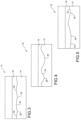
FIG. 1 is a top view of an assembly having a brazed joint between a first part and a second part, wherein the second part has wells for collection of excess braze material. -
FIG. 2 is a side view of the assembly ofFIG. 1 . -
FIG. 3 is a top view of an assembly similar toFIG. 1 but having wells defined between arc-shaped regions, constructed. -
FIG. 4 is a top view of an assembly similar toFIG. 1 but having smooth wells. -
FIG. 5 is a top view of an assembly similar to the assemblies ofFIGs. 2 and3 , but having a combination of a smooth well and a well defined between arc-shaped regions. -
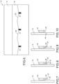
FIG. 6 is a top view of an assembly similar toFIG. 1 , but having collection capillaries at the wells, constructed in accordance with the present disclosure. -
FIG. 7 is a side view of the assembly ofFIG. 6 , illustrating the collection capillary as a hook, constructed in accordance with the present disclosure. -
FIG. 8 is a side view similar toFIG. 7 but having two plates as the collection capillary, constructed in accordance with the present disclosure. -
FIG. 9 is a side view similar toFIG. 7 but having a tube as the collection capillary, constructed in accordance with the present disclosure. -
FIG. 10 is a side view similar toFIG. 7 but having a hole formed in the first part as the collection capillary, constructed in accordance with the present disclosure. -
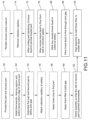
FIG. 11 is a flowchart illustrating a sample sequence of steps which may be involved in forming a brazed joint between two parts, in accordance with a method of the present disclosure. -
FIG. 12 is a photograph of an assembly having a brazed joint between a first part and a second part prepared in accordance with the methods of the present disclosure. -
FIG. 13 is a photograph of an assembly having a brazed joint between two parts prepared according to the prior art. - It should be understood that the drawings are not necessarily drawn to scale and that the disclosed embodiments are sometimes illustrated schematically and in partial views. It is to be further appreciated that the following detailed description is merely exemplary in nature and is not intended to limit the scope of the invention as claimed by the appended claims. In this regard, it is to be additionally appreciated that the described embodiments are not limited to use with certain applications. Hence, although the present disclosure is, for convenience of explanation, described as certain illustrative embodiments, it will be appreciated that it can be implemented in various other types of embodiments and in various other systems and environments.
- Referring now to the drawings, and with specific reference to
FIGs. 1-2 , anassembly 10 having a brazed joint 12 between at least a firstmetallic part 14 and a secondmetallic part 16 is shown. It will be understood, however, that theassembly 10 may be formed from more than two parts in some circumstances. The brazed joint 12 is located at ajoint gap 18 between afirst surface 20 of thefirst part 14 and asecond surface 22 of thesecond part 16. Notably, thesecond part 16 includes abottom edge 24 which has slopedregions 26 and at least one well 29 between two of the slopedregions 26. If theassembly 10 is positioned with thebottom edge 24 of thesecond part 16 oriented downwardly during formation of the brazed joint 12, the well(s) 29 serve(s) as a collection point for any excess braze material 32 (see further details below). In particular, with the assistance of gravity, the slopedregions 26 guides theexcess braze material 32 to the well(s) 29 for collection. The well(s) 29 may be strategically positioned at specific locations of theassembly 10 so as to avoid the flow of theexcess braze material 32 over any braze-sensitive features of theassembly 10. As used herein, `braze-sensitive features' are any features of theassembly 10 whose functions may be interfered with by the accumulation of excess braze material thereon. For example, braze-sensitive features may include, but are not limited to, cooling holes, mating surfaces, fasteners, and/or high stress regions of theassembly 10. In particular, the well(s) 29 may be positioned away from braze-sensitive features to prevent the accumulation of theexcess braze material 32 on such features. - Turning now to
FIGs. 3-5 , the well(s) 29 may have various alternative shapes. Although depicted as a sharp point between twosloped regions 26 inFIG. 1 , the well(s) 29 may also be defined between two arc-shapedregions 34 along the bottom edge 24 (FIG. 3 ). Alternatively, the well(s) 29 may be smooth as shown inFIG. 4 . As yet another possibility, the well(s) 29 may consist of a combination of one or more smooth wells and one or more wells defined between arc-shapedregions 34, as shown inFIG. 5 . It will be appreciated that well(s) 29 may take on various configurations such as these as well other alternative configurations and combinations depending on numerous design considerations. - Optionally, the
assembly 10 may further include one ormore collection capillaries 37 each associated with or located proximal to one of thewells 29, as shown inFIG. 6 . The collection capillary 37 draws theexcess braze material 32 away from the nearest well 29 by capillary action (or wicking). Thecollection capillary 37 may be formed from a metallic material, such as a metallic material similar to or identical to the metallic material forming either of theparts collection capillary 37 may be attached to the well 29, or it may be formed as an integral detail on one of theparts collection capillary 37 may be sacrificial and may be removed from theassembly 10 after collection of theexcess braze material 32 to allow the reclaiming of theexcess braze material 32 if desired. The ability to reclaim theexcess braze material 32 with thecollection capillary 37 may provide economic advantages, particularly when precious metals (e.g., gold, silver, palladium, platinum) are included in the braze filler material. - The collection capillaries 37 may have any structure capable of wicking the
excess braze material 32 away from thewells 29.FIGs. 7-10 depict several possible structures that may be used as thecollection capillary 37. As one possibility, thecollection capillary 37 may be ahook 38 that draws in theexcess braze liquid 32 by capillary action (FIG. 7 ). Alternatively, it may be formed between two metallic plates 40 (FIG. 8 ), or it may be a metallic tube 42 (FIG. 9 ). As yet another possibility, thecollection capillary 37 may be ahole 44 formed in thefirst part 14 as shown inFIG. 10 . In the latter case, thehole 44 may be positioned proximal to the well 29 so as to allow theexcess braze material 32 to flow from the well 29 into thehole 44. - The volume of the collection capillary 37 (i.e., the holding capacity of the collection capillary) may be calculated according equation (1) below where Vcapillary is the volume of the
collection capillary 37, and ΔVbraze is the difference between the theoretical braze filler volume (Vbraze) and the applied braze filler volume. In other words, Vcapillary may be equal to (or greater than) the amount of braze filler volume used that exceeds the theoretical braze filler volume.
- The theoretical braze filler volume (Vbraze) may be calculated from equation (2) below where Ajoint is the surface area of the brazed joint, and G is the width of the
joint gap 18. Thus, the size (i.e., holding volume) of thecollection capillary 37 may be adjusted according to the amount of excess braze filler material used (ΔVbraze).
- Turning now to
FIG. 11 , a series of steps that may be involved in fabricating theassembly 10 having the brazed joint 12 between thefirst part 14 and thesecond part 16 is shown. Beginning with afirst block 50, thefirst part 14 and thesecond part 16 may be provided. Thesloped regions 26 and the well(s) 29 may then be installed along thebottom edge 24 of thesecond part 16 according to anext block 52. As explained above, the well(s) 29 may be integrally designed with the parts of the brazed assembly and may be strategically positioned so as to prevent the flow of any excess braze material to braze-sensitive locations on theassembly 10. Theblock 52 may be carried out using various cutting or machining processes apparent to those skilled in the art. Thefirst part 14 may then be assembled with thesecond part 16 to define thejoint gap 18 between thefirst surface 20 and the second surface 22 (block 54). - Optionally, one or
more collection capillaries 37 may be attached to thesecond part 16 adjacent to a respective one of thewells 29 according to anoptional block 56.Block 56 may be carried out using a clamp, tack welding, or any other suitable method apparent to those skilled in the art. Alternatively, thecollection capillary 37 may be formed integrally with the first part 14 (e.g., as a hole in the first part) or integrally with thesecond part 16 during theblock 56. For example, excess material along thebottom edge 24 of thesecond part 16 may be folded over to create ahook 38 or a tube 42 (seeFIGs. 7 and 9 ). As another optional step, one or morebraze stop coatings 57 may be applied to thefirst surface 20 of thefirst part 14 as an additional measure to protect theassembly 10 from excess braze flow (optional block 58) (seeFIG. 1 ). In particular, thebraze stop coating 57 may protect the coated surface of thefirst part 14 from excess braze flow. In addition, the location of the braze stop coating(s) 57 on theassembly 10 may be chosen such that the braze stop coating(s) 57 may assist in directing the flow of excess braze material to the well(s) 29 and/or thecollection capillaries 37. - A braze filler may then be applied to the joint gap 18 (block 60), and the
parts second part 16 are pointed downwardly (block 62). According to the followingblocks joint gap 18 and wet thesurfaces regions 26 and collect at thewells 29 with gravity assistance (block 68). If collection capillaries 37 are used, the excess braze liquid may also be permitted to flow from thewells 29 into thecollection capillaries 37 by capillary action (optional block 70). Once the braze liquid is sufficiently distributed across thejoint gap 18, it may be allowed to cool and harden to provide the brazed joint 12 between the twoparts block 72. If collection capillaries 37 are used, they may be optionally removed according to anoptional block 74. For example, the collection capillaries may be removed by shearing, milling, machining, lasering, or another material removal process apparent to those skilled in the art. Furthermore, the excess braze material may be reclaimed from thecollection capillaries 37 and used for further brazing processes according to anoptional block 76. - It will be understood that steps shown in
FIG. 11 may be carried out in various alternative orders without interfering with the desired control over excess braze material flow. For example, the application of the braze filler (block 60) may be performed after orienting theassembly 10 so that the well(s) 29 are pointed downwardly (block 62). It will be understood that variations such as these are included within the scope of the present disclosure. - An example of an
assembly 10 is depicted inFIG. 12 . Theassembly 10 was fabricated using a firstmetallic part 80 and a secondmetallic part 82 with abottom edge 84 having slopedregions 86 and a well 89 between thesloped regions 86. The melted braze filler was permitted to flow between theparts bottom edge 84 of thesecond part 82 oriented downwardly to allow gravity to assist the flow of theexcess braze material 32 to thewell 89. As can be seen, all of theexcess braze material 32 collected at the well 89 of the assembly (collection point 'A'). This is in contrast with an assembly prepared in accordance with the prior art (seeFIG. 13 ). Specifically, the assembly ofFIG. 13 was fabricated using afirst part 90 and asecond part 92 having aflat bottom edge 94. As can be seen, theexcess braze material 32 dripped randomly in the assembly prepared in accordance with the prior art (collection points 'B'). Thus, the design strategy disclosed herein may be used to control the flow of excess braze material and direct it to designated regions of an assembly. - In general, it can therefore be seen that the technology disclosed herein has industrial applicability in a variety of settings including, but not limited to, applications using assemblies having a brazed joints between metallic parts. The technology disclosed herein implements part design features that enable the control of excess braze material flow to specified locations on the assembly. Specifically, the technology disclosed herein uses the assistance of gravity and strategically-positioned sloped regions and one or more wells along a bottom edge of one of the parts to guide the flow of the excess braze material to the wells. The position of the wells may be designed to direct the flow of the excess braze material away from any braze-sensitive features on the assembly. Optional collection capillaries may also be installed or formed integrally with one of the parts near the wells to allow the collection of the excess braze material from the wells. In addition, the collection capillaries may be removed from the assembly upon completion of the braze cycle to allow the reclaiming of the excess braze material for additional braze processes. This feature may have economic advantages, particularly when using expensive braze filler elements. The brazing strategy disclosed herein may be particularly advantageous for forming brazed joints between parts having geometries that make it difficult to control braze flow using the braze filler volume and the joint gap alone, such as large parts and/or parts having high surface variation. One non-limiting example would be for the manufacture of gas turbine engine parts, although a myriad of other applications exist. For example, it may be useful for forming brazed joints between panels or features of an afterburner liner of a gas turbine engine, or an exhaust nozzle liner of a gas turbine engine. It is expected that the technology disclosed herein may find wide industrial applicability in a wide range of areas such as, but not limited to, aerospace and automotive applications, power generation applications, and construction applications.
Claims (12)
- An assembly (10), comprising:a first part (14) including a first surface (20);a second part (16) including a second surface (22) and a bottom edge (24) having sloped regions (26) and at least one well (29) between the sloped regions;a brazed joint (12) j oining the first surface to the second surface to provide the assembly, the at least one well being configured to have collected excess braze material (32) from the brazed joint;the assembly is characterised by a collection capillary (37) adjacent to the at least one well (29), and wherein the collection capillary is configured to have collected the excess braze material (32) from the at least one well;wherein the sloped regions (26) are configured to have directed a flow of the excess braze material (32) from the brazed joint (12) to the at least one well (29); andwherein the collection capillary (37) is removable from the assembly or wherein the collection capillary is formed integrally with the second part (16).
- The assembly (10) of claim 1, wherein the at least one well (29) is positioned away from features of the assembly whose functions may be interfered with by the accumulation of excess braze material thereon.
- The assembly (10) of claim 1 or 2, wherein the collection capillary is a structure selected from a hook (38), a pair of plates (40), a tube (42), and a hole (44) in the first part (14).
- The assembly (10) of claim 1, 2 or 3, further comprising a braze stop coating on a portion of the first surface (20) of the first part (14), the braze stop being configured to have assisted in directing the flow of the excess braze material (32) to the at least one well (29).
- A method for fabricating an assembly (10) having a brazed joint (12) between a first surface (20) of a first part (14) and a second surface (22) of a second part (16), the second part including a bottom edge (24) having sloped regions (26) and at least one well (29) between the sloped regions, comprising:assembling the first surface with the second surface to define a joint gap (18) there between;applying a braze filler to the joint gap;orienting the first part and the second part so that the at least one well is pointed downwardly;melting the braze filler to a braze liquid;allowing the braze liquid to flow through the joint gap;allowing the braze liquid to cool and harden to provide the assembly having the brazed joint between the first part and the second part;the method is characterised by attaching a collection capillary (37) proximal to the at least one well (29) prior to melting the braze filler to a braze liquid;allowing any excess braze liquid from the joint gap to flow along the sloped regions for collection at the at least one well; andallowing the excess braze liquid (32) to flow from the at least one well (29) into the collection capillary (37) after allowing any excess braze liquid from the joint gap to flow along the sloped regions for collection at the at least one well.
- The method of claim 5, further comprising removing the collection capillary (37) from the assembly (10) after allowing the excess braze liquid (32) to flow from the at least one well (29) into the collection capillary;
- The method as claimed in claim 6, further comprising reclaiming the excess braze liquid from the collection capillary after removing the collection capillary from the assembly.
- The method of claim 5, 6 or 7, wherein the collection capillary (37) is a structure selected from a hook (38), a pair of parallel plates (40), and a tube (42).
- The method of any of claims 5 to 8, wherein the second part (16) further includes the collection capillary proximal (37) to the at least one well (29).
- The method of claim 9, wherein the method further comprises allowing the excess braze liquid (32) to flow from the at least one well to the collection capillary after allowing the excess braze liquid to flow along the sloped regions (26) for collection at the at least one well.
- The method of any of claims 5 to 10, wherein the first part (14) further includes a hole (44) located proximal to the at least one well (29).
- The method of claim 11, wherein the method further comprises allowing the excess braze liquid (32) to flow from the at least one well into the hole after allowing the excess braze liquid to flow along the sloped regions (26) for collection at the at least one well.
Applications Claiming Priority (1)
| Application Number | Priority Date | Filing Date | Title |
|---|---|---|---|
| US14/616,842 US9511452B2 (en) | 2015-02-09 | 2015-02-09 | Assemblies with brazed joints and methods of fabricating assemblies with brazed joints |
Publications (2)
| Publication Number | Publication Date |
|---|---|
| EP3053690A1 EP3053690A1 (en) | 2016-08-10 |
| EP3053690B1 true EP3053690B1 (en) | 2024-03-27 |
Family
ID=55527726
Family Applications (1)
| Application Number | Title | Priority Date | Filing Date |
|---|---|---|---|
| EP16154810.2A Active EP3053690B1 (en) | 2015-02-09 | 2016-02-09 | Assemblies with brazed joints and methods of fabricating assemblies with brazed joints |
Country Status (2)
| Country | Link |
|---|---|
| US (1) | US9511452B2 (en) |
| EP (1) | EP3053690B1 (en) |
Families Citing this family (3)
| Publication number | Priority date | Publication date | Assignee | Title |
|---|---|---|---|---|
| US10190502B2 (en) | 2016-06-23 | 2019-01-29 | Delavan Inc. | Brazing components and techniques |
| JPWO2019235500A1 (en) * | 2018-06-08 | 2021-07-01 | 株式会社ティラド | Brazed structure |
| US12601273B2 (en) | 2024-08-30 | 2026-04-14 | Pratt & Whitney Canada Corp. | Stator vane braze joints |
Citations (2)
| Publication number | Priority date | Publication date | Assignee | Title |
|---|---|---|---|---|
| JP3806850B2 (en) * | 1996-06-26 | 2006-08-09 | 昭和電工株式会社 | Manufacturing method of flat heat exchange tube |
| EP2216119A1 (en) * | 2009-01-27 | 2010-08-11 | Mitsubishi Heavy Industries | Manufacturing method of impeller |
Family Cites Families (25)
| Publication number | Priority date | Publication date | Assignee | Title |
|---|---|---|---|---|
| US1621001A (en) * | 1924-03-29 | 1927-03-15 | Allis Chalmers Mfg Co | Method of manufacturing turbines |
| GB851544A (en) * | 1957-10-28 | 1960-10-19 | English Electric Valve Co Ltd | Improvements in or relating to semi-conductor devices |
| US3140538A (en) * | 1960-01-20 | 1964-07-14 | Stewart Warner Corp | Method of forming a brazed joint |
| LU39519A1 (en) * | 1960-03-21 | 1962-06-11 | ||
| US3823464A (en) * | 1969-12-01 | 1974-07-16 | Chausson Usines Sa | Method of securing together two aluminum containing parts |
| FR2516419A1 (en) * | 1981-11-17 | 1983-05-20 | Peugeot | Low temp. brazing gearbox components - with composite brazing metal to contain volatile zinc |
| US4439250A (en) | 1983-06-09 | 1984-03-27 | International Business Machines Corporation | Solder/braze-stop composition |
| US4541282A (en) * | 1984-03-06 | 1985-09-17 | Honeywell Inc. | Method of producing a uniform fluid-tight seal between a thin, flexible member and a support and an apparatus utilizing the same |
| US4768382A (en) * | 1987-04-23 | 1988-09-06 | Honeywell Inc. | Method of producing a uniform fluid-tight seal between a thin, flexible member and a support and an apparatus utilizing the same |
| DE3831692A1 (en) * | 1988-09-17 | 1989-03-02 | Bbc Brown Boveri & Cie | Method for connecting the cover plate and/or foot piece on the one hand to the blade on the other by means of a brazing or jointing process |
| US4877083A (en) * | 1989-01-09 | 1989-10-31 | Modine Manufacturing Company | Brazed heat exchanger and method of making the same |
| JPH02299795A (en) | 1989-05-11 | 1990-12-12 | Showa Alum Corp | Brazing method for metallic material |
| JP2895197B2 (en) * | 1990-09-25 | 1999-05-24 | 株式会社不二精機製造所 | Continuous solder coating method and apparatus |
| US5310574A (en) * | 1992-05-12 | 1994-05-10 | Mask Technology, Inc. | Method for surface mount solder joints |
| US5374809A (en) * | 1993-05-12 | 1994-12-20 | The United States Of America As Represented By The Administrator Of The National Aeronautics And Space Administration | Induction heating coupler and annealer |
| JP3638215B2 (en) * | 1998-08-10 | 2005-04-13 | 象印マホービン株式会社 | Vacuum structure sealing method |
| JP2002079372A (en) * | 2000-09-06 | 2002-03-19 | Mitsubishi Materials Corp | Brazed joint sintered body |
| JP2003251458A (en) * | 2002-02-27 | 2003-09-09 | Mitsubishi Materials Corp | Brazed joint sintered body |
| US7140976B2 (en) * | 2003-09-02 | 2006-11-28 | Fu Sheng Industrial Co., Ltd. | Weight member for a golf club head |
| JP5819612B2 (en) | 2008-02-22 | 2015-11-24 | ジーケーエヌ シンター メタルズ、エル・エル・シー | Brazed component and method of forming brazed joints in the component |
| DE102008047076A1 (en) | 2008-09-12 | 2010-03-18 | Behr Gmbh & Co. Kg | Soldering component useful in a heat exchanger, comprises a first component and a second component, which are joined to each other in the area of a joining connection with a joining fit |
| ES2561037T3 (en) * | 2009-07-03 | 2016-02-24 | Alstom Technology Ltd | Method of replacing a cover of a guide blade of a gas turbine |
| US8684257B2 (en) * | 2011-08-15 | 2014-04-01 | GM Global Technology Operations LLC | Rotor for electric motor and brazing process |
| US20140332192A1 (en) | 2013-05-09 | 2014-11-13 | Trane International Inc. | Surface features to enhance brazing process |
| KR101878019B1 (en) * | 2014-05-12 | 2018-07-13 | 파나소닉 아이피 매니지먼트 가부시키가이샤 | Method for connecting piezoelectric element with cable board, piezoelectric element affixed with cable board and inkjet head using the same |
-
2015
- 2015-02-09 US US14/616,842 patent/US9511452B2/en active Active
-
2016
- 2016-02-09 EP EP16154810.2A patent/EP3053690B1/en active Active
Patent Citations (2)
| Publication number | Priority date | Publication date | Assignee | Title |
|---|---|---|---|---|
| JP3806850B2 (en) * | 1996-06-26 | 2006-08-09 | 昭和電工株式会社 | Manufacturing method of flat heat exchange tube |
| EP2216119A1 (en) * | 2009-01-27 | 2010-08-11 | Mitsubishi Heavy Industries | Manufacturing method of impeller |
Also Published As
| Publication number | Publication date |
|---|---|
| US9511452B2 (en) | 2016-12-06 |
| EP3053690A1 (en) | 2016-08-10 |
| US20160228996A1 (en) | 2016-08-11 |
Similar Documents
| Publication | Publication Date | Title |
|---|---|---|
| CN103567673B (en) | Method and system for welded pipe line | |
| DE102014100184B4 (en) | Process for joining two metallic workpieces as well as process for joining copper and aluminum | |
| US9511452B2 (en) | Assemblies with brazed joints and methods of fabricating assemblies with brazed joints | |
| KR20060115588A (en) | Superalloy Repair Methods and Inserts | |
| EP3165306A2 (en) | Additive manufacturing method for making holes bounded by thin walls in turbine components | |
| WO2014008037A1 (en) | Extruded brazing ring with integrated flux | |
| CN101998892B (en) | Brazed component and method of forming a brazed joint in a brazed component | |
| KR102902570B1 (en) | Method and system for modifying metal objects | |
| EP3225353B1 (en) | Method for joining heat transfer plates of a plate heat exchanger | |
| CZ20032800A3 (en) | Method of producing turbulences on inner surface of workpiece holes and corresponding workpieces | |
| EP2239083A1 (en) | Internally supported airfoil and method for internally supporting a hollow airfoil during manufacturing. | |
| JP6065564B2 (en) | Spot welding method | |
| WO2011091779A2 (en) | Method for bonding a titanium aluminide component to a dissimilar metal component, and bonded connection | |
| CN106964860B (en) | Method for welding and coating opening | |
| DE102006031388A1 (en) | Method for the repair and / or replacement of individual elements of a component of a gas turbine | |
| US10478920B2 (en) | Dual wall components for gas turbine engines | |
| EP3053689B1 (en) | Brazed joints and methods of forming brazed joints | |
| JP2000263247A (en) | Repair method of direction control crystal alloy parts | |
| EP1061240A3 (en) | Method of joining section elements of an exhaust system and exhaust system | |
| EP3113901A1 (en) | Method for repairing an airfoil, and cooling collar | |
| DE102009048957B4 (en) | A method of fusion welding a single crystal workpiece with a polycrystalline workpiece and rotor | |
| US20170312867A1 (en) | Method for repairing a component | |
| DE60300695T2 (en) | Method for dismantling a solder structure, eg. B. a honeycomb body with open side | |
| EP1669150A1 (en) | Braze bar with a pair of pins and an insert formed of dense graphit material ; Braze bar carrier system comprising such a braze bar | |
| US20160177747A1 (en) | Channel marker and related methods |
Legal Events
| Date | Code | Title | Description |
|---|---|---|---|
| PUAI | Public reference made under article 153(3) epc to a published international application that has entered the european phase |
Free format text: ORIGINAL CODE: 0009012 |
|
| AK | Designated contracting states |
Kind code of ref document: A1 Designated state(s): AL AT BE BG CH CY CZ DE DK EE ES FI FR GB GR HR HU IE IS IT LI LT LU LV MC MK MT NL NO PL PT RO RS SE SI SK SM TR |
|
| AX | Request for extension of the european patent |
Extension state: BA ME |
|
| RAP1 | Party data changed (applicant data changed or rights of an application transferred) |
Owner name: UNITED TECHNOLOGIES CORPORATION |
|
| STAA | Information on the status of an ep patent application or granted ep patent |
Free format text: STATUS: REQUEST FOR EXAMINATION WAS MADE |
|
| 17P | Request for examination filed |
Effective date: 20170210 |
|
| RBV | Designated contracting states (corrected) |
Designated state(s): AL AT BE BG CH CY CZ DE DK EE ES FI FR GB GR HR HU IE IS IT LI LT LU LV MC MK MT NL NO PL PT RO RS SE SI SK SM TR |
|
| STAA | Information on the status of an ep patent application or granted ep patent |
Free format text: STATUS: EXAMINATION IS IN PROGRESS |
|
| 17Q | First examination report despatched |
Effective date: 20181018 |
|
| RAP1 | Party data changed (applicant data changed or rights of an application transferred) |
Owner name: RAYTHEON TECHNOLOGIES CORPORATION |
|
| GRAP | Despatch of communication of intention to grant a patent |
Free format text: ORIGINAL CODE: EPIDOSNIGR1 |
|
| STAA | Information on the status of an ep patent application or granted ep patent |
Free format text: STATUS: GRANT OF PATENT IS INTENDED |
|
| INTG | Intention to grant announced |
Effective date: 20230901 |
|
| RIN1 | Information on inventor provided before grant (corrected) |
Inventor name: SAYERS, ROBERT J. Inventor name: PHILIPPONA, DERK S. Inventor name: BURD, STEVEN W. Inventor name: PATER, CHRISTOPHER M. |
|
| RAP3 | Party data changed (applicant data changed or rights of an application transferred) |
Owner name: RTX CORPORATION |
|
| GRAS | Grant fee paid |
Free format text: ORIGINAL CODE: EPIDOSNIGR3 |
|
| GRAA | (expected) grant |
Free format text: ORIGINAL CODE: 0009210 |
|
| STAA | Information on the status of an ep patent application or granted ep patent |
Free format text: STATUS: THE PATENT HAS BEEN GRANTED |
|
| AK | Designated contracting states |
Kind code of ref document: B1 Designated state(s): AL AT BE BG CH CY CZ DE DK EE ES FI FR GB GR HR HU IE IS IT LI LT LU LV MC MK MT NL NO PL PT RO RS SE SI SK SM TR |
|
| REG | Reference to a national code |
Ref country code: GB Ref legal event code: FG4D |
|
| REG | Reference to a national code |
Ref country code: CH Ref legal event code: EP |
|
| REG | Reference to a national code |
Ref country code: DE Ref legal event code: R096 Ref document number: 602016086514 Country of ref document: DE |
|
| REG | Reference to a national code |
Ref country code: IE Ref legal event code: FG4D |
|
| PG25 | Lapsed in a contracting state [announced via postgrant information from national office to epo] |
Ref country code: LT Free format text: LAPSE BECAUSE OF FAILURE TO SUBMIT A TRANSLATION OF THE DESCRIPTION OR TO PAY THE FEE WITHIN THE PRESCRIBED TIME-LIMIT Effective date: 20240327 |
|
| REG | Reference to a national code |
Ref country code: LT Ref legal event code: MG9D |
|
| PG25 | Lapsed in a contracting state [announced via postgrant information from national office to epo] |
Ref country code: GR Free format text: LAPSE BECAUSE OF FAILURE TO SUBMIT A TRANSLATION OF THE DESCRIPTION OR TO PAY THE FEE WITHIN THE PRESCRIBED TIME-LIMIT Effective date: 20240628 |
|
| PG25 | Lapsed in a contracting state [announced via postgrant information from national office to epo] |
Ref country code: RS Free format text: LAPSE BECAUSE OF FAILURE TO SUBMIT A TRANSLATION OF THE DESCRIPTION OR TO PAY THE FEE WITHIN THE PRESCRIBED TIME-LIMIT Effective date: 20240627 Ref country code: HR Free format text: LAPSE BECAUSE OF FAILURE TO SUBMIT A TRANSLATION OF THE DESCRIPTION OR TO PAY THE FEE WITHIN THE PRESCRIBED TIME-LIMIT Effective date: 20240327 |
|
| PG25 | Lapsed in a contracting state [announced via postgrant information from national office to epo] |
Ref country code: RS Free format text: LAPSE BECAUSE OF FAILURE TO SUBMIT A TRANSLATION OF THE DESCRIPTION OR TO PAY THE FEE WITHIN THE PRESCRIBED TIME-LIMIT Effective date: 20240627 Ref country code: NO Free format text: LAPSE BECAUSE OF FAILURE TO SUBMIT A TRANSLATION OF THE DESCRIPTION OR TO PAY THE FEE WITHIN THE PRESCRIBED TIME-LIMIT Effective date: 20240627 Ref country code: LT Free format text: LAPSE BECAUSE OF FAILURE TO SUBMIT A TRANSLATION OF THE DESCRIPTION OR TO PAY THE FEE WITHIN THE PRESCRIBED TIME-LIMIT Effective date: 20240327 Ref country code: HR Free format text: LAPSE BECAUSE OF FAILURE TO SUBMIT A TRANSLATION OF THE DESCRIPTION OR TO PAY THE FEE WITHIN THE PRESCRIBED TIME-LIMIT Effective date: 20240327 Ref country code: GR Free format text: LAPSE BECAUSE OF FAILURE TO SUBMIT A TRANSLATION OF THE DESCRIPTION OR TO PAY THE FEE WITHIN THE PRESCRIBED TIME-LIMIT Effective date: 20240628 Ref country code: FI Free format text: LAPSE BECAUSE OF FAILURE TO SUBMIT A TRANSLATION OF THE DESCRIPTION OR TO PAY THE FEE WITHIN THE PRESCRIBED TIME-LIMIT Effective date: 20240327 Ref country code: BG Free format text: LAPSE BECAUSE OF FAILURE TO SUBMIT A TRANSLATION OF THE DESCRIPTION OR TO PAY THE FEE WITHIN THE PRESCRIBED TIME-LIMIT Effective date: 20240327 |
|
| REG | Reference to a national code |
Ref country code: NL Ref legal event code: MP Effective date: 20240327 |
|
| PG25 | Lapsed in a contracting state [announced via postgrant information from national office to epo] |
Ref country code: SE Free format text: LAPSE BECAUSE OF FAILURE TO SUBMIT A TRANSLATION OF THE DESCRIPTION OR TO PAY THE FEE WITHIN THE PRESCRIBED TIME-LIMIT Effective date: 20240327 Ref country code: LV Free format text: LAPSE BECAUSE OF FAILURE TO SUBMIT A TRANSLATION OF THE DESCRIPTION OR TO PAY THE FEE WITHIN THE PRESCRIBED TIME-LIMIT Effective date: 20240327 |
|
| PG25 | Lapsed in a contracting state [announced via postgrant information from national office to epo] |
Ref country code: NL Free format text: LAPSE BECAUSE OF FAILURE TO SUBMIT A TRANSLATION OF THE DESCRIPTION OR TO PAY THE FEE WITHIN THE PRESCRIBED TIME-LIMIT Effective date: 20240327 |
|
| REG | Reference to a national code |
Ref country code: AT Ref legal event code: MK05 Ref document number: 1669447 Country of ref document: AT Kind code of ref document: T Effective date: 20240327 |
|
| PG25 | Lapsed in a contracting state [announced via postgrant information from national office to epo] |
Ref country code: NL Free format text: LAPSE BECAUSE OF FAILURE TO SUBMIT A TRANSLATION OF THE DESCRIPTION OR TO PAY THE FEE WITHIN THE PRESCRIBED TIME-LIMIT Effective date: 20240327 |
|
| PG25 | Lapsed in a contracting state [announced via postgrant information from national office to epo] |
Ref country code: IS Free format text: LAPSE BECAUSE OF FAILURE TO SUBMIT A TRANSLATION OF THE DESCRIPTION OR TO PAY THE FEE WITHIN THE PRESCRIBED TIME-LIMIT Effective date: 20240727 |
|
| PG25 | Lapsed in a contracting state [announced via postgrant information from national office to epo] |
Ref country code: PT Free format text: LAPSE BECAUSE OF FAILURE TO SUBMIT A TRANSLATION OF THE DESCRIPTION OR TO PAY THE FEE WITHIN THE PRESCRIBED TIME-LIMIT Effective date: 20240729 Ref country code: SM Free format text: LAPSE BECAUSE OF FAILURE TO SUBMIT A TRANSLATION OF THE DESCRIPTION OR TO PAY THE FEE WITHIN THE PRESCRIBED TIME-LIMIT Effective date: 20240327 |
|
| PG25 | Lapsed in a contracting state [announced via postgrant information from national office to epo] |
Ref country code: ES Free format text: LAPSE BECAUSE OF FAILURE TO SUBMIT A TRANSLATION OF THE DESCRIPTION OR TO PAY THE FEE WITHIN THE PRESCRIBED TIME-LIMIT Effective date: 20240327 |
|
| PG25 | Lapsed in a contracting state [announced via postgrant information from national office to epo] |
Ref country code: CZ Free format text: LAPSE BECAUSE OF FAILURE TO SUBMIT A TRANSLATION OF THE DESCRIPTION OR TO PAY THE FEE WITHIN THE PRESCRIBED TIME-LIMIT Effective date: 20240327 Ref country code: EE Free format text: LAPSE BECAUSE OF FAILURE TO SUBMIT A TRANSLATION OF THE DESCRIPTION OR TO PAY THE FEE WITHIN THE PRESCRIBED TIME-LIMIT Effective date: 20240327 |
|
| PG25 | Lapsed in a contracting state [announced via postgrant information from national office to epo] |
Ref country code: AT Free format text: LAPSE BECAUSE OF FAILURE TO SUBMIT A TRANSLATION OF THE DESCRIPTION OR TO PAY THE FEE WITHIN THE PRESCRIBED TIME-LIMIT Effective date: 20240327 |
|
| PG25 | Lapsed in a contracting state [announced via postgrant information from national office to epo] |
Ref country code: PL Free format text: LAPSE BECAUSE OF FAILURE TO SUBMIT A TRANSLATION OF THE DESCRIPTION OR TO PAY THE FEE WITHIN THE PRESCRIBED TIME-LIMIT Effective date: 20240327 |
|
| PG25 | Lapsed in a contracting state [announced via postgrant information from national office to epo] |
Ref country code: SK Free format text: LAPSE BECAUSE OF FAILURE TO SUBMIT A TRANSLATION OF THE DESCRIPTION OR TO PAY THE FEE WITHIN THE PRESCRIBED TIME-LIMIT Effective date: 20240327 |
|
| PG25 | Lapsed in a contracting state [announced via postgrant information from national office to epo] |
Ref country code: SM Free format text: LAPSE BECAUSE OF FAILURE TO SUBMIT A TRANSLATION OF THE DESCRIPTION OR TO PAY THE FEE WITHIN THE PRESCRIBED TIME-LIMIT Effective date: 20240327 Ref country code: SK Free format text: LAPSE BECAUSE OF FAILURE TO SUBMIT A TRANSLATION OF THE DESCRIPTION OR TO PAY THE FEE WITHIN THE PRESCRIBED TIME-LIMIT Effective date: 20240327 Ref country code: RO Free format text: LAPSE BECAUSE OF FAILURE TO SUBMIT A TRANSLATION OF THE DESCRIPTION OR TO PAY THE FEE WITHIN THE PRESCRIBED TIME-LIMIT Effective date: 20240327 Ref country code: PT Free format text: LAPSE BECAUSE OF FAILURE TO SUBMIT A TRANSLATION OF THE DESCRIPTION OR TO PAY THE FEE WITHIN THE PRESCRIBED TIME-LIMIT Effective date: 20240729 Ref country code: PL Free format text: LAPSE BECAUSE OF FAILURE TO SUBMIT A TRANSLATION OF THE DESCRIPTION OR TO PAY THE FEE WITHIN THE PRESCRIBED TIME-LIMIT Effective date: 20240327 Ref country code: IS Free format text: LAPSE BECAUSE OF FAILURE TO SUBMIT A TRANSLATION OF THE DESCRIPTION OR TO PAY THE FEE WITHIN THE PRESCRIBED TIME-LIMIT Effective date: 20240727 Ref country code: ES Free format text: LAPSE BECAUSE OF FAILURE TO SUBMIT A TRANSLATION OF THE DESCRIPTION OR TO PAY THE FEE WITHIN THE PRESCRIBED TIME-LIMIT Effective date: 20240327 Ref country code: EE Free format text: LAPSE BECAUSE OF FAILURE TO SUBMIT A TRANSLATION OF THE DESCRIPTION OR TO PAY THE FEE WITHIN THE PRESCRIBED TIME-LIMIT Effective date: 20240327 Ref country code: CZ Free format text: LAPSE BECAUSE OF FAILURE TO SUBMIT A TRANSLATION OF THE DESCRIPTION OR TO PAY THE FEE WITHIN THE PRESCRIBED TIME-LIMIT Effective date: 20240327 Ref country code: AT Free format text: LAPSE BECAUSE OF FAILURE TO SUBMIT A TRANSLATION OF THE DESCRIPTION OR TO PAY THE FEE WITHIN THE PRESCRIBED TIME-LIMIT Effective date: 20240327 |
|
| PG25 | Lapsed in a contracting state [announced via postgrant information from national office to epo] |
Ref country code: IT Free format text: LAPSE BECAUSE OF FAILURE TO SUBMIT A TRANSLATION OF THE DESCRIPTION OR TO PAY THE FEE WITHIN THE PRESCRIBED TIME-LIMIT Effective date: 20240327 |
|
| PG25 | Lapsed in a contracting state [announced via postgrant information from national office to epo] |
Ref country code: IT Free format text: LAPSE BECAUSE OF FAILURE TO SUBMIT A TRANSLATION OF THE DESCRIPTION OR TO PAY THE FEE WITHIN THE PRESCRIBED TIME-LIMIT Effective date: 20240327 |
|
| REG | Reference to a national code |
Ref country code: DE Ref legal event code: R097 Ref document number: 602016086514 Country of ref document: DE |
|
| PG25 | Lapsed in a contracting state [announced via postgrant information from national office to epo] |
Ref country code: DK Free format text: LAPSE BECAUSE OF FAILURE TO SUBMIT A TRANSLATION OF THE DESCRIPTION OR TO PAY THE FEE WITHIN THE PRESCRIBED TIME-LIMIT Effective date: 20240327 |
|
| PG25 | Lapsed in a contracting state [announced via postgrant information from national office to epo] |
Ref country code: DK Free format text: LAPSE BECAUSE OF FAILURE TO SUBMIT A TRANSLATION OF THE DESCRIPTION OR TO PAY THE FEE WITHIN THE PRESCRIBED TIME-LIMIT Effective date: 20240327 |
|
| PLBE | No opposition filed within time limit |
Free format text: ORIGINAL CODE: 0009261 |
|
| STAA | Information on the status of an ep patent application or granted ep patent |
Free format text: STATUS: NO OPPOSITION FILED WITHIN TIME LIMIT |
|
| 26N | No opposition filed |
Effective date: 20250103 |
|
| PG25 | Lapsed in a contracting state [announced via postgrant information from national office to epo] |
Ref country code: SI Free format text: LAPSE BECAUSE OF FAILURE TO SUBMIT A TRANSLATION OF THE DESCRIPTION OR TO PAY THE FEE WITHIN THE PRESCRIBED TIME-LIMIT Effective date: 20240327 |
|
| PG25 | Lapsed in a contracting state [announced via postgrant information from national office to epo] |
Ref country code: MC Free format text: LAPSE BECAUSE OF FAILURE TO SUBMIT A TRANSLATION OF THE DESCRIPTION OR TO PAY THE FEE WITHIN THE PRESCRIBED TIME-LIMIT Effective date: 20240327 |
|
| REG | Reference to a national code |
Ref country code: CH Ref legal event code: PL |
|
| PG25 | Lapsed in a contracting state [announced via postgrant information from national office to epo] |
Ref country code: LU Free format text: LAPSE BECAUSE OF NON-PAYMENT OF DUE FEES Effective date: 20250209 |
|
| PG25 | Lapsed in a contracting state [announced via postgrant information from national office to epo] |
Ref country code: CH Free format text: LAPSE BECAUSE OF NON-PAYMENT OF DUE FEES Effective date: 20250228 |
|
| REG | Reference to a national code |
Ref country code: BE Ref legal event code: MM Effective date: 20250228 |
|
| PG25 | Lapsed in a contracting state [announced via postgrant information from national office to epo] |
Ref country code: BE Free format text: LAPSE BECAUSE OF NON-PAYMENT OF DUE FEES Effective date: 20250228 |
|
| PG25 | Lapsed in a contracting state [announced via postgrant information from national office to epo] |
Ref country code: IE Free format text: LAPSE BECAUSE OF NON-PAYMENT OF DUE FEES Effective date: 20250209 |
|
| PGFP | Annual fee paid to national office [announced via postgrant information from national office to epo] |
Ref country code: GB Payment date: 20260121 Year of fee payment: 11 |
|
| PGFP | Annual fee paid to national office [announced via postgrant information from national office to epo] |
Ref country code: DE Payment date: 20260121 Year of fee payment: 11 |
|
| PGFP | Annual fee paid to national office [announced via postgrant information from national office to epo] |
Ref country code: FR Payment date: 20260121 Year of fee payment: 11 |
|
| PG25 | Lapsed in a contracting state [announced via postgrant information from national office to epo] |
Ref country code: CY Free format text: LAPSE BECAUSE OF FAILURE TO SUBMIT A TRANSLATION OF THE DESCRIPTION OR TO PAY THE FEE WITHIN THE PRESCRIBED TIME-LIMIT Effective date: 20240327 |
|
| PG25 | Lapsed in a contracting state [announced via postgrant information from national office to epo] |
Ref country code: TR Free format text: LAPSE BECAUSE OF FAILURE TO SUBMIT A TRANSLATION OF THE DESCRIPTION OR TO PAY THE FEE WITHIN THE PRESCRIBED TIME-LIMIT Effective date: 20240327 |