EP3052779B1 - Valve, assembly for degassing a coolant, and method for degassing the coolant - Google Patents
Valve, assembly for degassing a coolant, and method for degassing the coolant Download PDFInfo
- Publication number
- EP3052779B1 EP3052779B1 EP14784395.7A EP14784395A EP3052779B1 EP 3052779 B1 EP3052779 B1 EP 3052779B1 EP 14784395 A EP14784395 A EP 14784395A EP 3052779 B1 EP3052779 B1 EP 3052779B1
- Authority
- EP
- European Patent Office
- Prior art keywords
- valve
- refrigerant
- membrane
- tank
- duct
- Prior art date
- Legal status (The legal status is an assumption and is not a legal conclusion. Google has not performed a legal analysis and makes no representation as to the accuracy of the status listed.)
- Active
Links
- 239000002826 coolant Substances 0.000 title claims description 40
- 238000007872 degassing Methods 0.000 title claims description 36
- 238000000034 method Methods 0.000 title claims description 7
- 239000012528 membrane Substances 0.000 claims description 37
- 239000003507 refrigerant Substances 0.000 claims description 37
- 238000001816 cooling Methods 0.000 claims description 15
- 230000000694 effects Effects 0.000 claims description 7
- 238000009834 vaporization Methods 0.000 claims description 4
- 230000008016 vaporization Effects 0.000 claims description 4
- 238000004891 communication Methods 0.000 claims description 2
- 239000007789 gas Substances 0.000 description 7
- 230000033001 locomotion Effects 0.000 description 7
- LYCAIKOWRPUZTN-UHFFFAOYSA-N Ethylene glycol Chemical compound OCCO LYCAIKOWRPUZTN-UHFFFAOYSA-N 0.000 description 4
- XLYOFNOQVPJJNP-UHFFFAOYSA-N water Substances O XLYOFNOQVPJJNP-UHFFFAOYSA-N 0.000 description 4
- 239000007788 liquid Substances 0.000 description 3
- 238000007789 sealing Methods 0.000 description 3
- 230000033228 biological regulation Effects 0.000 description 2
- 230000000295 complement effect Effects 0.000 description 2
- 230000007423 decrease Effects 0.000 description 2
- 239000012530 fluid Substances 0.000 description 2
- WGCNASOHLSPBMP-UHFFFAOYSA-N hydroxyacetaldehyde Natural products OCC=O WGCNASOHLSPBMP-UHFFFAOYSA-N 0.000 description 2
- 239000000203 mixture Substances 0.000 description 2
- 238000013021 overheating Methods 0.000 description 2
- 238000010079 rubber tapping Methods 0.000 description 2
- 238000009835 boiling Methods 0.000 description 1
- 230000003247 decreasing effect Effects 0.000 description 1
- 230000007613 environmental effect Effects 0.000 description 1
- 239000007792 gaseous phase Substances 0.000 description 1
- 238000010438 heat treatment Methods 0.000 description 1
- 230000001939 inductive effect Effects 0.000 description 1
- 239000007791 liquid phase Substances 0.000 description 1
- 230000007257 malfunction Effects 0.000 description 1
- 238000000926 separation method Methods 0.000 description 1
- 229920002994 synthetic fiber Polymers 0.000 description 1
Images



Classifications
-
- F—MECHANICAL ENGINEERING; LIGHTING; HEATING; WEAPONS; BLASTING
- F01—MACHINES OR ENGINES IN GENERAL; ENGINE PLANTS IN GENERAL; STEAM ENGINES
- F01P—COOLING OF MACHINES OR ENGINES IN GENERAL; COOLING OF INTERNAL-COMBUSTION ENGINES
- F01P11/00—Component parts, details, or accessories not provided for in, or of interest apart from, groups F01P1/00 - F01P9/00
- F01P11/02—Liquid-coolant filling, overflow, venting, or draining devices
- F01P11/0204—Filling
- F01P11/0209—Closure caps
- F01P11/0238—Closure caps with overpressure valves or vent valves
-
- F—MECHANICAL ENGINEERING; LIGHTING; HEATING; WEAPONS; BLASTING
- F16—ENGINEERING ELEMENTS AND UNITS; GENERAL MEASURES FOR PRODUCING AND MAINTAINING EFFECTIVE FUNCTIONING OF MACHINES OR INSTALLATIONS; THERMAL INSULATION IN GENERAL
- F16K—VALVES; TAPS; COCKS; ACTUATING-FLOATS; DEVICES FOR VENTING OR AERATING
- F16K17/00—Safety valves; Equalising valves, e.g. pressure relief valves
- F16K17/18—Safety valves; Equalising valves, e.g. pressure relief valves opening on surplus pressure on either side
- F16K17/19—Equalising valves predominantly for tanks
- F16K17/196—Equalising valves predominantly for tanks spring-loaded
Definitions
- the invention relates to a cooling circuit valve, suitable for being positioned on a degassing tank intended to receive a refrigerant, in particular a coolant for the cooling circuit of a heat engine.
- the invention also relates to an assembly for degassing a refrigerant, comprising such a valve and such a tank, as well as a method for degassing the refrigerant.
- the temperature conditions to which the coolant, such as water/glycol mixtures, is subjected cause vapors to form within the cooling circuit.
- the cooling system is pressurized using an adjustable valve.
- the cooling circuit may include more than 5 liters of liquid, which considerably increases the thermal inertia of the engine.
- a first solution consists of cutting all circulation of the coolant in the circuit when the engine is started up. This function is performed by a thermostat that regulates the circulation of the liquid as a function of the temperature of the engine.
- a second solution consists of acting directly on the water pump responsible for setting the coolant in motion within the circuit.
- the water pump is disconnected mechanically or electrically, so as to block the circulation of the liquid upon start-up, and once the heat balance is achieved, to allow the coolant to circulate in the circuit.
- Another alternative is to cut the circulation of the coolant in the circuit using controlled gates.
- the degassing tank In the cooling circuit of a heat engine, it is common for the degassing tank to be supplied with coolant directly with no cutoff member such as a gate or thermostat, for example in the case of engine head degassing.
- no cutoff member such as a gate or thermostat
- Another approach is to cut the circulation of the coolant inside the degassing tank, as long as the internal temperature has not reached a value close to the regulation temperature.
- This cutoff may be done using a gate controlled either by the internal temperature of the tank, in particular by thermostatic elements, or by the internal pressure of the tank.
- This gate is generally positioned outside the degassing tank. This has the drawback that the factory filling of a coolant circuit is more difficult and requires using a bypass system.
- DE-A-10 2011 078293 teaches to fit the cutoff gate inside the degassing tank.
- This cutoff gate includes a non-return valve comprising a body movable relative to a seat. This body is lifted up against the elastic effort of a spring when the tank pressure exceeds a first threshold value. As a result, the refrigerant circulation inside the tank is cut as long as the tank pressure is below the first threshold value.
- the degassing tank is also equipped with an overpressure flap and with an air intake flap.
- the cutoff gate body is rigid, thereby inducing abrupt opening and closing of the gate.
- the invention aims to resolve the aforementioned drawbacks, by proposing an improved valve for a cooling circuit.
- the invention relates to a cooling circuit valve, suitable for being positioned on a degassing tank intended to receive a refrigerant, in particular a coolant for a heat engine, said valve comprising at least one first refrigerant supply duct, a second air intake duct inside the valve, a third refrigerant and/or air exhaust duct, in particular an exhaust for coolant or a gas formed by vaporization of that coolant, a connecting volume that is in communication with an inner volume of the degassing tank when the valve is positioned on the degassing tank, a flap selectively opening a passage for an incoming stream of air going from the second duct toward the connecting volume, a flap for selectively opening a passage for an outgoing stream of refrigerant and/or air, going from the connecting volume toward the third duct, and, a regulator which, under the effect of the pressure in the connecting volume, selectively opens a passage of an incoming refrigerant stream going from the first duct toward the connecting volume.
- the regulator is opened and closed more smoothly thanks to the elastic membrane.
- the gas leaks are then reduced and the tank pressure is better controlled.
- the valve may incorporate one or more of the following features, considered in any technically allowable combination:
- the invention also relates to a degassing assembly for a refrigerant, comprising a valve and a degassing tank intended to receive a refrigerant, the valve being as previously defined and fixed in the upper part of the degassing tank in a recess provided to that end.
- the invention thus relates to a method for degassing a refrigerant inside a degassing tank.
- this method uses a valve as previously described and comprises steps in which:
- FIGS 1 to 11 show a degassing assembly 2 according to the invention.
- this degassing assembly 2 is intended to be integrated into the cooling circuit of a heat engine.
- This degassing assembly 2 comprises a tank 30 and a valve 20 assembled on the tank 30.
- the tank 30 comprises an outer body 32 that delimits an inner volume V30 of the tank 30.
- the outer body 32 comprises a neck 40 that delimits an inner orifice O30 and which includes an outer thread 400.
- the orifice O30 forms a recess for receiving the valve 20 in the upper part of the tank 30.
- the tank 30 also comprises a stopper 38 including a tapping 380.
- the tapping 380 of the stopper 38 has a screw pitch complementary to the screw pitch of the thread 400 of the neck 40.
- the stopper 38 can be screwed in the neck 40, which makes it possible to close the tank 30 in the upper part thereof.
- the stopper 38 therefore makes it possible to shut the valve 20 inside the tank 30, in the recess O30.
- the outer body 32 of the tank 30 also comprises, in the upper part, several refrigerant inlet connectors 36, and its lower part, an outlet connector 34 for the same refrigerant.
- the tank 30 generally includes one or two inlet connectors 36. Only one of these connectors is shown in figure 1 , having specified that any other connectors are situated in planes other than that of this figure.
- the refrigerant is a coolant, in particular a water/glycol mixture.
- the refrigerant may be of any type suitable for the present application.
- an axis Z2 is defined, which is vertical when the wheels of the vehicle equipped with the assembly 2 rest on a horizontal ground.
- the terms “bottom” and “lower” correspond to an orientation toward the ground, while the terms “top” and “upper” correspond to an orientation opposite the ground.
- the coolant flows from the valve 20 toward the inside of the tank 30 generally along that vertical axis Z2.
- the connector 34 extends parallel to the vertical axis Z2, while the connectors 36 extend radially to the axis Z2.
- Also defined are an incoming stream F1 of coolant in the valve 20 via the inlet connectors 36 and an outgoing stream F2 of coolant toward the outside of the tank 30 via the outlet connector 34.
- the coolant flows downward by simple gravitational effect.
- FIGS 2 to 11 show the valve 20 according to the invention in more detail.
- the valve 20 comprises a housing 204 and a seat 202 that are positioned inside the neck 40 and that are hollow parts made from a synthetic material and symmetrical in revolution around the axis Z2.
- the seat 202 is positioned below the housing 204 and defines a lower surface S202.
- duct refers to a passage volume for a fluid
- a “connector” refers to the structure surrounding that volume
- a single-piece member 208 is positioned comprising a main body 2082 and a cap 2080.
- the member 208 is a part of revolution centered on the axis Z2.
- the cap 2080 includes an edge 2084 curved upward, with a substantially annular profile centered on the axis Z2.
- the edge 2084 is better visible in figure 5 .
- a part 2040 belonging to the housing 204 is positioned below the member 208.
- a spiral spring 216 that surrounds the axis Z2 is inserted between this part 2040 and the member 208.
- the edge 2084 of the cap 2080 bears upward against a seal 218 surrounding the main body 2082 of the member 208.
- the seal 218 is hollow, positioned inside the housing 204 and with symmetry of revolution around the axis Z2.
- the spring 216 exerts an upward elastic force on the member 208, which pushes that member 208 against the seal 218.
- An abutment part 200 is positioned above the member 208.
- a spiral spring 210 surrounds the axis Z2 and is inserted between the abutment part 200 and the seal 218. More specifically, the spring 210 is inserted between the abutment part 200 and a bearing blade 219 of the spring 210 on the seal 218.
- the spring 210 therefore constitutes means for elastically loading the seal 218 downward, i.e., against the housing 204.
- the valve 20 comprises several ducts 201 for supplying the valve with coolant, only one of which is shown in the figures.
- the ducts 201 extend the connectors 36 of the outer body 32 of the tank 30; they represent the outlet of the connectors 36 in the valve 20.
- the ducts 201 each emerge on a regulator 100 included in the valve 20.
- a sealing device 2220 Positioned between the seat 202 and the neck 40 of the tank 30 is a sealing device 2220 making it possible to prevent the passage of the coolant outside the duct 201.
- the regulator 100 comprises an elastically deformable membrane 206, a bearing blade 212 and a calibration spring 214.
- the membrane 206 is a part of revolution around the axis Z2 whereof the section considered in a plane containing the axis Z2 is generally L-shaped.
- the membrane 206 therefore comprises an upper edge 206D and a lower edge 206E.
- the edges 206D and 206E are fixed between the housing 204 and the seat 202.
- a plane XY2 is defined perpendicular to the axis Z2 and delimits the valve 20.
- This plane XY2 is positioned at the lower end of the valve 20. It is therefore tangent to the surface S202 of the seat 202. It is considered that the volume located below the plane XY2 forms the inner volume V30 of the tank 30 and that the volume located above the plane XY2 forms a connecting volume V20 connecting the valve 20 with the inner volume V30 of the tank 30. More specifically, the volume V20 is shown in figure 3 .
- first volume V201 delimited between the membrane 206 and the plane XY2 and a second volume V202 defined between the member 208 and the plane XY2 inside the seat 202 and the housing 204.
- the plane XY2 marks the separation between the valve 20 and the tank 30, and it is therefore possible to deduce therefrom that the volume V20 forms the connection between the valve 20 and the tank 30.
- the membrane 206 is made up of three parts 206A, 206B and 206C.
- the first part 206A defines the upper edge 206D, it is oriented toward the coolant supply duct 201, and it seals the duct 201 when the regulator 100 is closed.
- the second part 206B partially defines the connecting volume V20 of the valve 20 and defines the lower edge 206E.
- the third part 206C connects the first part 206A and the second part 206B to each other.
- the third part 206C may be described as a middle part of the membrane 206, framed by the parts 206A and 206B.
- the third part 206C bears against the seat 202 when the regulator 100 is closed, i.e., the third part 206C extends parallel to the duct 201 in which the membrane 206 is positioned and therefore parallel to the incoming stream F1 of coolant. This arrangement prevents coolant from infiltrating from the duct 201 toward the inside of the valve 20 when the regulator 100 is closed.
- the membrane includes two ribs 206N1 and 206N2 that are positioned at the third part 206C and that bear against the seat 202 when the regulator 100 is closed.
- the ribs 206N1 and 206N2 have an annular shape centered on the axis Z2 and have an outer surface, i.e., oriented toward the seat 202, respectively denoted S206N1 and S206N2.
- the surfaces S206N1 and S206N2 are concentric surfaces relative to a point of the axis Z2 and together form a contact surface S206C of the membrane 206 with the seat 202. Having a double bearing surface makes it possible to have double sealing at the contact between the membrane 206 and the seat 202.
- the bearing blade 212 and the calibration spring 214 are positioned above the third part 206C of the membrane 206.
- the spring 214 is inserted between the housing 204 and the blade 212 and therefore provides an elastic force that tends to press the third part 206C of the membrane 206 downward against the seat 202. This elastic loading elastic force makes it possible to keep the regulator 100 in the closed position.
- the valve 20 also comprises, in the upper part, an air suction duct 203, i.e., a passage in which air is suctioned.
- the suction duct 203 passes between the neck 40 and the stopper 38 of the tank 30 and emerges on a volume V203 situated above the member 208.
- the valve 20 In case of overpressure, the valve 20 must secure the cooling circuit.
- the valve 20 comprises a passage, or exhaust duct 205, for the coolant, then in liquid or gaseous phase, and/or air.
- the duct 205 is a refrigerant and/or air exhaust duct, in particular exhaust for coolant or a gas resulting from vaporization of the coolant.
- This duct 205 is better shown in figures 8 and 9 and is identical to the duct 203, with the exception that the circulation direction of the fluid is not the same.
- the coolant supply ducts 201 form first ducts within the valve 20, the air intake duct 203 is a second duct and the refrigerant and/or air exhaust duct 205 is a third duct.
- FIGS 4 to 9 show the different states of the valve 20 depending on the inner pressure of the degassing tank 30, i.e., the pressure of the connecting volume V20. This inner pressure of the tank depends on the heat balance of the engine.
- the first step of the method occurs in case of a vacuum inside the tank 30, that vacuum being related to the heat balance of the engine.
- air is suctioned into the air intake duct 203 provided to that end.
- the air therefore travels between the neck 40 and the stopper 38, as shown by the arrows F3, and enters the volume V203.
- the increase in the pressure of the air in the volume V203 pushes the member 208 downward against the action of the spring 216.
- This movement makes it possible to free a passage P1 between the cap 2080 of the member 208 and the seal 218.
- the air therefore flows, in the direction of the arrows F4, in that passage P1 going from the second duct 203 toward the volume V202 belonging to the connecting volume V20.
- the spring 216, the member 208 and the seal 218 therefore form a first flap C1 for selectively opening the passage P1 for the incoming air stream F3.
- the air flows, in the direction of the arrows F5, into the volume V201, then into the inner volume V30 of the tank 30.
- the pressure inside the tank 30 is increased.
- the regulator 100 opens. More specifically, the elastic loading means formed by the calibration spring 214 and the bearing blade 212 of the regulator 100 do not oppose sufficient resistance against the pressure of the volume V201. The pressure prevailing in the volume V201 of the connecting volume V20 then lifts the first part 206A and the third part 206C of the membrane 206 upward. This movement is shown in figure 7 by the arrows D1. The coolant can therefore flow into a passage P2 between the third part 206C of the membrane 206 and the seat 202. The passage P2 goes from the first duct 201 to the first volume V201 belonging to the connecting volume V20. The regulator 100 is therefore a regulator for selectively opening the passage P2 for the incoming stream F1. The coolant is poured at the output of the regulator 100 into the tank 30, as shown by the arrows F6.
- a reference pressure for example comprised between 0.6 and 0.7 relative bar
- valve 20 makes it possible to pressurize the cooling circuit to prevent any vaporization of the coolant during normal operation.
- the gas next escapes between the neck 40 and the stopper 38. This movement is shown in figure 8 by arrows F8.
- the flap C2 is therefore a flap for selectively opening the passage P3 for the outgoing stream F7 of gas and/or coolant. This opening configuration of the flap C2, aiming to discharge the exhaust gases, occurs only in case of a "heat wave", or overheating of the engine, this overheating in practice coming from an internal anomaly.
- the regulator 100 for selective opening of the passage P2 for the incoming stream F1 of coolant closes, as the pressure exerted on the second part 206B of the membrane 206 is not sufficient to compensate the elastic return of the spring 214.
- the third part 206C of the membrane 206 therefore returns, bearing against the seat 202, thereby closing the passage P2.
- Figures 10 and 11 show a configuration for manual opening of the coolant supply duct 201.
- This configuration is obtained by unscrewing the stopper 38 from the neck 40. This unscrewing causes the valve 20 to move upward. Consequently, the sealing device 2020 of the seat 200 no longer bears sealably against the outer body 32 of the tank 30. There is therefore a passage of coolant between the seat 202 and the neck 40. This flow is shown in figure 11 by arrows F9. The movement of the valve 20 relative to the tank 30 is shown in figure 11 by an arrow D3.
- This manual opening of the coolant supply duct is particularly advantageous, since it makes it possible to open the passage P2 in case of malfunction of the regulator 100.
- the reference pressure considered relative to the atmospheric pressure
- the overpressure value may be comprised between 0.8 and 3.5 bars, based on the configuration of the valve 20 and its component elements.
- the neck 40 may include an abutment that is complementary with respect to an abutment formed on the stopper 38, thereby allowing the user to feel when the stopper 38 is completely screwed into the neck 40.
- valve 20 comprises a single refrigerant supply duct 201.
- valve 20 may be integrated into the cooling circuit of a power battery of an electric engine.
- the degassing assembly 2 and the valve 20 may be adapted in terms of cost, functionality and performance.
Landscapes
- Engineering & Computer Science (AREA)
- General Engineering & Computer Science (AREA)
- Mechanical Engineering (AREA)
- Chemical & Material Sciences (AREA)
- Combustion & Propulsion (AREA)
- Safety Valves (AREA)
- Valve Housings (AREA)
Description
- The invention relates to a cooling circuit valve, suitable for being positioned on a degassing tank intended to receive a refrigerant, in particular a coolant for the cooling circuit of a heat engine. The invention also relates to an assembly for degassing a refrigerant, comprising such a valve and such a tank, as well as a method for degassing the refrigerant.
- In the field of cooling systems for heat engines, the temperature conditions to which the coolant, such as water/glycol mixtures, is subjected cause vapors to form within the cooling circuit. To eliminate this boiling, the cooling system is pressurized using an adjustable valve.
- In order to comply with current environmental regulations, engine heating time tends to decrease. To that end, the thermal inertia of the engine upon start-up thereof should be decreased. However, in certain specific vehicles, the cooling circuit may include more than 5 liters of liquid, which considerably increases the thermal inertia of the engine.
- A first solution consists of cutting all circulation of the coolant in the circuit when the engine is started up. This function is performed by a thermostat that regulates the circulation of the liquid as a function of the temperature of the engine.
- A second solution consists of acting directly on the water pump responsible for setting the coolant in motion within the circuit. The water pump is disconnected mechanically or electrically, so as to block the circulation of the liquid upon start-up, and once the heat balance is achieved, to allow the coolant to circulate in the circuit.
- Another alternative is to cut the circulation of the coolant in the circuit using controlled gates.
- In the cooling circuit of a heat engine, it is common for the degassing tank to be supplied with coolant directly with no cutoff member such as a gate or thermostat, for example in the case of engine head degassing. Thus, another approach is to cut the circulation of the coolant inside the degassing tank, as long as the internal temperature has not reached a value close to the regulation temperature. This cutoff may be done using a gate controlled either by the internal temperature of the tank, in particular by thermostatic elements, or by the internal pressure of the tank. This gate is generally positioned outside the degassing tank. This has the drawback that the factory filling of a coolant circuit is more difficult and requires using a bypass system.
- To overcome this problem,
DE-A-10 2011 078293 teaches to fit the cutoff gate inside the degassing tank. This cutoff gate includes a non-return valve comprising a body movable relative to a seat. This body is lifted up against the elastic effort of a spring when the tank pressure exceeds a first threshold value. As a result, the refrigerant circulation inside the tank is cut as long as the tank pressure is below the first threshold value. The degassing tank is also equipped with an overpressure flap and with an air intake flap. The cutoff gate body is rigid, thereby inducing abrupt opening and closing of the gate. - The invention aims to resolve the aforementioned drawbacks, by proposing an improved valve for a cooling circuit.
- To that end, the invention relates to a cooling circuit valve, suitable for being positioned on a degassing tank intended to receive a refrigerant, in particular a coolant for a heat engine, said valve comprising at least one first refrigerant supply duct, a second air intake duct inside the valve, a third refrigerant and/or air exhaust duct, in particular an exhaust for coolant or a gas formed by vaporization of that coolant, a connecting volume that is in communication with an inner volume of the degassing tank when the valve is positioned on the degassing tank, a flap selectively opening a passage for an incoming stream of air going from the second duct toward the connecting volume, a flap for selectively opening a passage for an outgoing stream of refrigerant and/or air, going from the connecting volume toward the third duct, and, a regulator which, under the effect of the pressure in the connecting volume, selectively opens a passage of an incoming refrigerant stream going from the first duct toward the connecting volume. According to the invention, the regulator comprises a a membrane that is elastically deformable under the effect of the pressure in the connecting volume. Also, the regulator comprises a seat and a housing between which the membrane is fixed by both of its edges.
- Owing to the invention, the regulator is opened and closed more smoothly thanks to the elastic membrane. The gas leaks are then reduced and the tank pressure is better controlled. According to advantageous but non-mandatory aspects of the invention, the valve may incorporate one or more of the following features, considered in any technically allowable combination:
- The membrane comprises a first part positioned across from the first duct and which seals the first duct when the regulator is closed, a second part that partially delimits the connecting volume, and a third part that connects the first part and the second part and which bears against the seat when the regulator is closed.
- The second part of the membrane is capable of lifting, under the effect of the pressure in the connecting volume, the first and third parts of the membrane toward the housing, thereby opening the passage for the incoming refrigerant stream between the seat and the membrane.
- The regulator comprises means for elastically loading the membrane, which include a calibration spring and a blade bearing on the third part of the membrane, the spring being inserted between the blade and the housing.
- A contact surface between the third part of the membrane and the seat is parallel to the incoming refrigerant stream.
- The third part of the membrane includes ribs that bear against the seat when the regulator is closed.
- The ribs have contact surfaces with the seat that are annular and concentric relative to a central axis of the valve.
- The invention also relates to a degassing assembly for a refrigerant, comprising a valve and a degassing tank intended to receive a refrigerant, the valve being as previously defined and fixed in the upper part of the degassing tank in a recess provided to that end.
- The invention thus relates to a method for degassing a refrigerant inside a degassing tank. According to the invention, this method uses a valve as previously described and comprises steps in which:
- a) when a vacuum occurs in the connecting volume, i.e., when the internal pressure of the tank drops below the atmospheric pressure, air is suctioned into the second duct and the flap opening the passage for the incoming stream of air opens,
- b) when the pressure inside the tank reaches atmospheric pressure, the flap opening the incoming air stream passage closes,
- c) when the pressure of the tank reaches a reference value, which is greater than the atmospheric pressure, the opening regulator of the passage for the incoming refrigerant stream opens, and
- d) when the pressure in the tank reaches an overpressure value, which is greater than the reference value, the flap opening a passage for the outgoing stream opens, thereby allowing the refrigerant and/or air to escape.
- The invention will be better understood and other advantages thereof will appear more clearly in light of the following description of one embodiment of a valve according to its principle, provided solely as a non-limiting example and done in reference to the appended drawings, in which:
-
figure 1 is a cross-section of a degassing assembly according to the invention, comprising a degassing tank and a valve that is also according to the invention, -
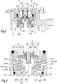
figure 2 is an enlarged view of detail II offigure 1 , -
figure 3 is an enlarged view of detail III offigure 2 , -
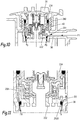
figure 4 is a cross-section similar tofigure 2 , showing the valve in case of vacuum in the degassing tank, -
figure 5 is an enlarged view of detail V offigure 4 , -
figure 6 is a cross-section similar tofigures 2 and4 , showing the valve in a configuration where the internal circulation of the refrigerant is open, -
figure 7 is an enlarged view of detail VII offigure 6 , -
figure 8 is a cross-section similar tofigures 2 ,4 and6 , showing the valve in case of overpressure in the degassing tank, -
figure 9 is an enlarged view of detail IX offigure 8 , -
figure 10 is a cross-section similar tofigures 2 ,4 ,6 and8 , showing the valve in case of filling of the cooling circuit or in case of bypass, i.e., in a configuration where the circulation of the refrigerant is continuous, independently of the internal pressure, and -
figure 11 is an enlarged view of detail IX offigure 10 . -
Figures 1 to 11 show adegassing assembly 2 according to the invention. In this example, thisdegassing assembly 2 is intended to be integrated into the cooling circuit of a heat engine. - This
degassing assembly 2 comprises atank 30 and avalve 20 assembled on thetank 30. - The
tank 30 comprises anouter body 32 that delimits an inner volume V30 of thetank 30. In its upper part, theouter body 32 comprises aneck 40 that delimits an inner orifice O30 and which includes anouter thread 400. The orifice O30 forms a recess for receiving thevalve 20 in the upper part of thetank 30. Thetank 30 also comprises astopper 38 including a tapping 380. The tapping 380 of thestopper 38 has a screw pitch complementary to the screw pitch of thethread 400 of theneck 40. Thus, thestopper 38 can be screwed in theneck 40, which makes it possible to close thetank 30 in the upper part thereof. Thestopper 38 therefore makes it possible to shut thevalve 20 inside thetank 30, in the recess O30. Theouter body 32 of thetank 30 also comprises, in the upper part, severalrefrigerant inlet connectors 36, and its lower part, anoutlet connector 34 for the same refrigerant. In practice, thetank 30 generally includes one or twoinlet connectors 36. Only one of these connectors is shown infigure 1 , having specified that any other connectors are situated in planes other than that of this figure. - In the example, the refrigerant is a coolant, in particular a water/glycol mixture. Alternatively, the refrigerant may be of any type suitable for the present application.
- To facilitate the spatial identification of the different parts of the
assembly 2, an axis Z2 is defined, which is vertical when the wheels of the vehicle equipped with theassembly 2 rest on a horizontal ground. Hereafter, the terms "bottom" and "lower" correspond to an orientation toward the ground, while the terms "top" and "upper" correspond to an orientation opposite the ground. The coolant flows from thevalve 20 toward the inside of thetank 30 generally along that vertical axis Z2. Theconnector 34 extends parallel to the vertical axis Z2, while theconnectors 36 extend radially to the axis Z2. Also defined are an incoming stream F1 of coolant in thevalve 20 via theinlet connectors 36 and an outgoing stream F2 of coolant toward the outside of thetank 30 via theoutlet connector 34. The coolant flows downward by simple gravitational effect. -
Figures 2 to 11 show thevalve 20 according to the invention in more detail. - The
valve 20 comprises ahousing 204 and aseat 202 that are positioned inside theneck 40 and that are hollow parts made from a synthetic material and symmetrical in revolution around the axis Z2. Theseat 202 is positioned below thehousing 204 and defines a lower surface S202. - In the present description, the term "duct" refers to a passage volume for a fluid, whereas a "connector" refers to the structure surrounding that volume.
- At the center of the
valve 20, i.e., inside thehousing 204, a single-piece member 208 is positioned comprising amain body 2082 and acap 2080. Themember 208 is a part of revolution centered on the axis Z2. Thecap 2080 includes anedge 2084 curved upward, with a substantially annular profile centered on the axis Z2. Theedge 2084 is better visible infigure 5 . Apart 2040 belonging to thehousing 204 is positioned below themember 208. Aspiral spring 216 that surrounds the axis Z2 is inserted between thispart 2040 and themember 208. In the configuration offigure 2 , theedge 2084 of thecap 2080 bears upward against aseal 218 surrounding themain body 2082 of themember 208. Theseal 218 is hollow, positioned inside thehousing 204 and with symmetry of revolution around the axis Z2. Thespring 216 exerts an upward elastic force on themember 208, which pushes thatmember 208 against theseal 218. - An
abutment part 200 is positioned above themember 208. Aspiral spring 210 surrounds the axis Z2 and is inserted between theabutment part 200 and theseal 218. More specifically, thespring 210 is inserted between theabutment part 200 and abearing blade 219 of thespring 210 on theseal 218. Thespring 210 therefore constitutes means for elastically loading theseal 218 downward, i.e., against thehousing 204. - The
valve 20 comprisesseveral ducts 201 for supplying the valve with coolant, only one of which is shown in the figures. Theducts 201 extend theconnectors 36 of theouter body 32 of thetank 30; they represent the outlet of theconnectors 36 in thevalve 20. Theducts 201 each emerge on aregulator 100 included in thevalve 20. - Positioned between the
seat 202 and theneck 40 of thetank 30 is a sealing device 2220 making it possible to prevent the passage of the coolant outside theduct 201. - The
regulator 100 comprises an elasticallydeformable membrane 206, abearing blade 212 and acalibration spring 214. Themembrane 206 is a part of revolution around the axis Z2 whereof the section considered in a plane containing the axis Z2 is generally L-shaped. Themembrane 206 therefore comprises anupper edge 206D and alower edge 206E. Theedges housing 204 and theseat 202. - As shown in
figures 1 and3 , a plane XY2 is defined perpendicular to the axis Z2 and delimits thevalve 20. This plane XY2 is positioned at the lower end of thevalve 20. It is therefore tangent to the surface S202 of theseat 202. It is considered that the volume located below the plane XY2 forms the inner volume V30 of thetank 30 and that the volume located above the plane XY2 forms a connecting volume V20 connecting thevalve 20 with the inner volume V30 of thetank 30. More specifically, the volume V20 is shown infigure 3 . It comprises a first volume V201 delimited between themembrane 206 and the plane XY2 and a second volume V202 defined between themember 208 and the plane XY2 inside theseat 202 and thehousing 204. The plane XY2 marks the separation between thevalve 20 and thetank 30, and it is therefore possible to deduce therefrom that the volume V20 forms the connection between thevalve 20 and thetank 30. - The
membrane 206 is made up of threeparts first part 206A defines theupper edge 206D, it is oriented toward thecoolant supply duct 201, and it seals theduct 201 when theregulator 100 is closed. Thesecond part 206B partially defines the connecting volume V20 of thevalve 20 and defines thelower edge 206E. Thethird part 206C connects thefirst part 206A and thesecond part 206B to each other. Thethird part 206C may be described as a middle part of themembrane 206, framed by theparts third part 206C bears against theseat 202 when theregulator 100 is closed, i.e., thethird part 206C extends parallel to theduct 201 in which themembrane 206 is positioned and therefore parallel to the incoming stream F1 of coolant. This arrangement prevents coolant from infiltrating from theduct 201 toward the inside of thevalve 20 when theregulator 100 is closed. Furthermore, the membrane includes two ribs 206N1 and 206N2 that are positioned at thethird part 206C and that bear against theseat 202 when theregulator 100 is closed. The ribs 206N1 and 206N2 have an annular shape centered on the axis Z2 and have an outer surface, i.e., oriented toward theseat 202, respectively denoted S206N1 and S206N2. The surfaces S206N1 and S206N2 are concentric surfaces relative to a point of the axis Z2 and together form a contact surface S206C of themembrane 206 with theseat 202. Having a double bearing surface makes it possible to have double sealing at the contact between themembrane 206 and theseat 202. - The
bearing blade 212 and thecalibration spring 214 are positioned above thethird part 206C of themembrane 206. Thespring 214 is inserted between thehousing 204 and theblade 212 and therefore provides an elastic force that tends to press thethird part 206C of themembrane 206 downward against theseat 202. This elastic loading elastic force makes it possible to keep theregulator 100 in the closed position. - As better shown in
figures 4 and 5 , thevalve 20 also comprises, in the upper part, anair suction duct 203, i.e., a passage in which air is suctioned. Thesuction duct 203 passes between theneck 40 and thestopper 38 of thetank 30 and emerges on a volume V203 situated above themember 208. - In case of overpressure, the
valve 20 must secure the cooling circuit. To that end, thevalve 20 comprises a passage, orexhaust duct 205, for the coolant, then in liquid or gaseous phase, and/or air. In other words, theduct 205 is a refrigerant and/or air exhaust duct, in particular exhaust for coolant or a gas resulting from vaporization of the coolant. Thisduct 205 is better shown infigures 8 and 9 and is identical to theduct 203, with the exception that the circulation direction of the fluid is not the same. - The
coolant supply ducts 201 form first ducts within thevalve 20, theair intake duct 203 is a second duct and the refrigerant and/orair exhaust duct 205 is a third duct. -
Figures 4 to 9 show the different states of thevalve 20 depending on the inner pressure of thedegassing tank 30, i.e., the pressure of the connecting volume V20. This inner pressure of the tank depends on the heat balance of the engine. - As shown in
figures 4 and 5 , the first step of the method occurs in case of a vacuum inside thetank 30, that vacuum being related to the heat balance of the engine. Thus, air is suctioned into theair intake duct 203 provided to that end. The air therefore travels between theneck 40 and thestopper 38, as shown by the arrows F3, and enters the volume V203. The increase in the pressure of the air in the volume V203 pushes themember 208 downward against the action of thespring 216. This movement makes it possible to free a passage P1 between thecap 2080 of themember 208 and theseal 218. The air therefore flows, in the direction of the arrows F4, in that passage P1 going from thesecond duct 203 toward the volume V202 belonging to the connecting volume V20. Thespring 216, themember 208 and theseal 218 therefore form a first flap C1 for selectively opening the passage P1 for the incoming air stream F3. - At the outlet of the flap C1, the air flows, in the direction of the arrows F5, into the volume V201, then into the inner volume V30 of the
tank 30. As a result, the pressure inside thetank 30 is increased. - When the pressure in the connecting volume V20 reaches the outside pressure, or atmospheric pressure, the air ceases to be suctioned through the
second duct 203, since pressure equilibrium has been achieved. If no pressure is exerted on the upper part of themember 208, the action of theelastic spring 216 moves themember 208 upward. This movement means that theedges 2084 of thecap 2080 come into contact with theseal 218, thereby closing the passage P1 for the air. - When the pressure in the volume V20 reaches a reference pressure, for example comprised between 0.6 and 0.7 relative bar, the
regulator 100 opens. More specifically, the elastic loading means formed by thecalibration spring 214 and thebearing blade 212 of theregulator 100 do not oppose sufficient resistance against the pressure of the volume V201. The pressure prevailing in the volume V201 of the connecting volume V20 then lifts thefirst part 206A and thethird part 206C of themembrane 206 upward. This movement is shown infigure 7 by the arrows D1. The coolant can therefore flow into a passage P2 between thethird part 206C of themembrane 206 and theseat 202. The passage P2 goes from thefirst duct 201 to the first volume V201 belonging to the connecting volume V20. Theregulator 100 is therefore a regulator for selectively opening the passage P2 for the incoming stream F1. The coolant is poured at the output of theregulator 100 into thetank 30, as shown by the arrows F6. - Thus, the
valve 20 makes it possible to pressurize the cooling circuit to prevent any vaporization of the coolant during normal operation. - When the pressure inside the
tank 30 reaches an overpressure value, for example equal to 1.4 relative bar, the pressure of the connecting volume V20 of thevalve 20 causes a movement of the assembly formed by themember 208 and theseal 218 upward against the action of the elastic force of thespring 210. This pressure force is shown, infigure 9 , by the arrows D2. A passage P3 therefore opens between theseal 218 and thehousing 204. Theseal 218, theblade 219, thespring 210 and thehousing 204 therefore form a second flap C2 for selectively opening the passage P3. When the flap C2 is open, the air and/or coolant escapes through the passage P3 upward, as shown by the arrows F7. - The gas next escapes between the
neck 40 and thestopper 38. This movement is shown infigure 8 by arrows F8. The flap C2 is therefore a flap for selectively opening the passage P3 for the outgoing stream F7 of gas and/or coolant. This opening configuration of the flap C2, aiming to discharge the exhaust gases, occurs only in case of a "heat wave", or overheating of the engine, this overheating in practice coming from an internal anomaly. - This discharge of the gas causes a pressure drop within the
tank 30. When the pressure decreases below the overpressure value, for example equal to 1.4 relative bar, the pressure prevailing inside thetank 30 is not sufficient to compensate the elastic return of thespring 210. Thus, theseal 218 returns bearing downward against thehousing 204. The flap C2 is closed. - In parallel, the
regulator 100 for selective opening of the passage P2 for the incoming stream F1 of coolant closes, as the pressure exerted on thesecond part 206B of themembrane 206 is not sufficient to compensate the elastic return of thespring 214. Thethird part 206C of themembrane 206 therefore returns, bearing against theseat 202, thereby closing the passage P2. -
Figures 10 and 11 show a configuration for manual opening of thecoolant supply duct 201. This configuration is obtained by unscrewing thestopper 38 from theneck 40. This unscrewing causes thevalve 20 to move upward. Consequently, thesealing device 2020 of theseat 200 no longer bears sealably against theouter body 32 of thetank 30. There is therefore a passage of coolant between theseat 202 and theneck 40. This flow is shown infigure 11 by arrows F9. The movement of thevalve 20 relative to thetank 30 is shown infigure 11 by an arrow D3. This manual opening of the coolant supply duct is particularly advantageous, since it makes it possible to open the passage P2 in case of malfunction of theregulator 100. - In an alternative that is not shown, the reference pressure, considered relative to the atmospheric pressure, may be comprised between 0.1 and 1 bar, while the overpressure value, still considered relative to the atmospheric pressure, may be comprised between 0.8 and 3.5 bars, based on the configuration of the
valve 20 and its component elements. - According to another alternative that is not shown, the
neck 40 may include an abutment that is complementary with respect to an abutment formed on thestopper 38, thereby allowing the user to feel when thestopper 38 is completely screwed into theneck 40. - According to another alternative that is not shown, the
valve 20 comprises a singlerefrigerant supply duct 201. - According to another alternative that is not shown, the
valve 20 may be integrated into the cooling circuit of a power battery of an electric engine. - Furthermore, the technical features of the various alternatives described above may be combined with each other in whole or in part. Thus, the
degassing assembly 2 and thevalve 20 may be adapted in terms of cost, functionality and performance.
Claims (9)
- A cooling circuit valve (20), suitable for being positioned on a degassing tank (30) intended to receive a refrigerant, in particular a coolant for a heat engine, said valve comprising:- at least one first refrigerant supply duct (201),- a second air intake duct (203) inside the valve,- a third refrigerant and/or air exhaust duct (205), in particular an exhaust for coolant or a gas formed by vaporization of that coolant, and- a connecting volume (V20) that is in communication with an inner volume (V30) of the degassing tank when the valve is positioned on the degassing tank,- a flap (C1) selectively opening a passage (P1) for an incoming stream (F3) of air going from the second duct toward the connecting volume,- a flap (C2) for selectively opening a passage (P3) for an outgoing stream (F8) of refrigerant and/or air, going from the connecting volume toward the third duct, and- a regulator (100) which, under the effect of the pressure in the connecting volume (V20), selectively opens a passage (P2) of an incoming refrigerant stream (F1) going from the first duct (201) toward the connecting volume (V20),wherein the regulator (100) comprises a membrane (206) that is elastically deformable under the effect of the pressure in the connecting volume (V20) and
characterized
in that the regulator (100) comprises a seat (202) and a housing (204) between which the membrane (206) is fixed by both of its edges (206D, 206E). - The valve (20) according to claim 1, characterized in that the membrane (206) comprises:- a first part (206A) positioned across from the first duct (201) and which seals the first duct (201) when the regulator (100) is closed,- a second part (206B) that partially delimits the connecting volume (V20), and- a third part (206C) that connects the first part (206A) and the second part (206B) and which bears against the seat (202) when the regulator (100) is closed.
- The valve (20) according to claim 2, characterized in that the second part (206B) of the membrane (206) is capable of lifting, under the effect of the pressure in the connecting volume (V20), the first (206A) and third (206C) parts of the membrane toward the housing (202), thereby opening the passage (P2) for the incoming refrigerant stream (F1) between the seat (202) and the membrane (206).
- The valve (20) according to one of claims 2 and 3, characterized in that the regulator (100) comprises means (214, 212) for elastically loading the membrane (206), which include a calibration spring (214) and a blade (212) bearing on the third part (206C) of the membrane (206), the spring (214) being inserted between the blade (212) and the housing (204).
- The valve (20) according to one of claims 2 to 4, characterized in that a contact surface (S206C) between the third part (206C) of the membrane (206) and the seat (202) is parallel to the incoming refrigerant stream (F1).
- The valve according to any claim 2 to 5, characterized in that the third part (206C) of the membrane (206) includes ribs (206N1, 206N2) that bear against the seat (202) when the regulator is closed.
- The valve according to claim 6, characterized in that the ribs (206N1, 206N2) have contact surfaces (S206N1, S206N2) with the seat (202) that are annular and concentric relative to a central axis (Z2) of the valve.
- A degassing assembly (2) for a refrigerant, comprising a valve (20) and a degassing tank (30) intended to receive a refrigerant, characterized in that the valve (20) is according to one of claims 1 to 7 and is fixed in the upper part of the degassing tank (30) in a recess (O30) provided to that end.
- A method for degassing a refrigerant inside a degassing tank (30), characterized in that the method uses a valve (20) according to any claim 1 to 7 and in that it comprises steps in which:a) when a vacuum occurs in the connecting volume (V20), i.e., when the internal pressure of the tank (30) drops below the atmospheric pressure, air is suctioned into the second duct (203) and the flap (C1) opening the passage (P1) for the incoming stream (F3) of air opens,b) when the pressure inside the tank (30) reaches atmospheric pressure, the flap (C1) opening the incoming air stream (F3) passage (P1) closes,c) when the pressure of the tank reaches a reference value, which is greater than the atmospheric pressure, the opening regulator (100) of the passage (P2) for the incoming refrigerant stream (F1) opens, andd) when the pressure in the tank reaches an overpressure value, which is greater than the reference value, the flap (C2) opening a passage (P3) for the outgoing stream (F8) opens, thereby allowing the refrigerant and/or air to escape.
Applications Claiming Priority (2)
| Application Number | Priority Date | Filing Date | Title |
|---|---|---|---|
| FR1359504A FR3011306B1 (en) | 2013-10-01 | 2013-10-01 | VALVE, COOLANT DEGASSING ASSEMBLY, AND COOLANT DEGASSING METHOD |
| PCT/US2014/058152 WO2015050830A1 (en) | 2013-10-01 | 2014-09-30 | Valve, assembly for degassing a coolant, and method for degassing the coolant |
Publications (2)
| Publication Number | Publication Date |
|---|---|
| EP3052779A1 EP3052779A1 (en) | 2016-08-10 |
| EP3052779B1 true EP3052779B1 (en) | 2019-11-06 |
Family
ID=49998387
Family Applications (1)
| Application Number | Title | Priority Date | Filing Date |
|---|---|---|---|
| EP14784395.7A Active EP3052779B1 (en) | 2013-10-01 | 2014-09-30 | Valve, assembly for degassing a coolant, and method for degassing the coolant |
Country Status (4)
| Country | Link |
|---|---|
| EP (1) | EP3052779B1 (en) |
| CN (1) | CN105593488B (en) |
| FR (1) | FR3011306B1 (en) |
| WO (1) | WO2015050830A1 (en) |
Family Cites Families (9)
| Publication number | Priority date | Publication date | Assignee | Title |
|---|---|---|---|---|
| DE3832103C2 (en) * | 1988-09-21 | 1996-08-29 | Blau Kg Kraftfahrzeugtech | Sealing lid for the filling opening of a coolant tank in automotive cooling systems |
| DE10034762A1 (en) * | 2000-03-13 | 2002-01-31 | Heinrich Reutter | Sealing cap for vehicle radiator; has inner part with valve arrangement having valve bodies biased against seal seats inside cap, where valve bodies are lifted by excess pressure inside radiator |
| KR100448737B1 (en) * | 2001-10-09 | 2004-09-16 | 현대자동차주식회사 | Radiator cap apparatus |
| DE20201082U1 (en) * | 2002-01-24 | 2003-06-05 | Reutter, Heinrich, 71336 Waiblingen | Cover for automobile radiator |
| KR100975226B1 (en) * | 2008-07-25 | 2010-08-10 | 현대자동차주식회사 | Coolant Surge Tank |
| US20100206882A1 (en) * | 2009-02-13 | 2010-08-19 | Wessels Timothy J | Multi chamber coolant tank |
| CN201756996U (en) * | 2010-07-27 | 2011-03-09 | 上海联谊汽车拖拉机工贸有限公司 | Expansion water tank cover assembly structure |
| DE102010033715A1 (en) * | 2010-08-07 | 2012-02-09 | Audi Ag | Expansion tank for a coolant circuit |
| DE102011078293B4 (en) * | 2011-06-29 | 2017-06-29 | Röchling Automotive AG & Co. KG | Expansion tank with a liquid check valve body and a relative to this movably received on this gas vacuum valve body and such a valve structure supporting lid for a surge tank |
-
2013
- 2013-10-01 FR FR1359504A patent/FR3011306B1/en not_active Expired - Fee Related
-
2014
- 2014-09-30 EP EP14784395.7A patent/EP3052779B1/en active Active
- 2014-09-30 WO PCT/US2014/058152 patent/WO2015050830A1/en not_active Ceased
- 2014-09-30 CN CN201480054277.0A patent/CN105593488B/en not_active Expired - Fee Related
Non-Patent Citations (1)
| Title |
|---|
| None * |
Also Published As
| Publication number | Publication date |
|---|---|
| FR3011306A1 (en) | 2015-04-03 |
| CN105593488B (en) | 2019-03-01 |
| CN105593488A (en) | 2016-05-18 |
| WO2015050830A1 (en) | 2015-04-09 |
| EP3052779A1 (en) | 2016-08-10 |
| FR3011306B1 (en) | 2016-02-05 |
Similar Documents
| Publication | Publication Date | Title |
|---|---|---|
| ES2223881T3 (en) | SYSTEM OF REGULATION OF A GAS FLOW. | |
| US20130139903A1 (en) | Expansion reservoir for a coolant circuit | |
| US20100206882A1 (en) | Multi chamber coolant tank | |
| KR101542989B1 (en) | Valve for vehicle | |
| US10941864B2 (en) | Drain valve, exterior aircraft light unit and power supply box | |
| KR20180040010A (en) | Safe valve for high pressure regulator | |
| US9638094B2 (en) | Charge air cooler with integrated adjustable drain mechanism | |
| KR101134645B1 (en) | Air Shut Off Valve for Fuel Cell Electric Vehicle | |
| CN101968134A (en) | Fuel vapor vent valve with dynamic pressure relief | |
| SE0802445A1 (en) | expansion Tank | |
| US9856777B2 (en) | Dual chamber coolant reservoir | |
| EP1307675A2 (en) | Valve having a movable seat and a movable needle | |
| US6012434A (en) | Fuel system vapor separator for an internal combustion engine | |
| US9683479B2 (en) | Safety cap device for controlling pressure in radiator and method for controlling pressure using the same | |
| US7188588B2 (en) | Cooling system and coolant reservoir for a cooling system | |
| WO2015050830A1 (en) | Valve, assembly for degassing a coolant, and method for degassing the coolant | |
| KR101341992B1 (en) | Dual pressure adjustable no-load radiator valve | |
| JP5672808B2 (en) | Engine cooling system | |
| CN201106481Y (en) | Radiator expansion water tank lid | |
| KR100489116B1 (en) | Radiator cap | |
| US20080170949A1 (en) | Manually operated vacuum pump and refill device | |
| EP2326861B1 (en) | Valve assembly | |
| CN109906316B (en) | Screw compressor for a commercial vehicle | |
| CN215244318U (en) | Overfills and Vehicles | |
| ES2263917T3 (en) | LIQUID MODULE FOR THE GENERATION OF CONSTANT LIQUID PRESSURES. |
Legal Events
| Date | Code | Title | Description |
|---|---|---|---|
| PUAI | Public reference made under article 153(3) epc to a published international application that has entered the european phase |
Free format text: ORIGINAL CODE: 0009012 |
|
| 17P | Request for examination filed |
Effective date: 20160218 |
|
| AK | Designated contracting states |
Kind code of ref document: A1 Designated state(s): AL AT BE BG CH CY CZ DE DK EE ES FI FR GB GR HR HU IE IS IT LI LT LU LV MC MK MT NL NO PL PT RO RS SE SI SK SM TR |
|
| AX | Request for extension of the european patent |
Extension state: BA ME |
|
| DAX | Request for extension of the european patent (deleted) | ||
| GRAP | Despatch of communication of intention to grant a patent |
Free format text: ORIGINAL CODE: EPIDOSNIGR1 |
|
| STAA | Information on the status of an ep patent application or granted ep patent |
Free format text: STATUS: GRANT OF PATENT IS INTENDED |
|
| INTG | Intention to grant announced |
Effective date: 20190509 |
|
| GRAS | Grant fee paid |
Free format text: ORIGINAL CODE: EPIDOSNIGR3 |
|
| GRAA | (expected) grant |
Free format text: ORIGINAL CODE: 0009210 |
|
| STAA | Information on the status of an ep patent application or granted ep patent |
Free format text: STATUS: THE PATENT HAS BEEN GRANTED |
|
| AK | Designated contracting states |
Kind code of ref document: B1 Designated state(s): AL AT BE BG CH CY CZ DE DK EE ES FI FR GB GR HR HU IE IS IT LI LT LU LV MC MK MT NL NO PL PT RO RS SE SI SK SM TR |
|
| REG | Reference to a national code |
Ref country code: GB Ref legal event code: FG4D |
|
| REG | Reference to a national code |
Ref country code: CH Ref legal event code: EP Ref country code: AT Ref legal event code: REF Ref document number: 1199000 Country of ref document: AT Kind code of ref document: T Effective date: 20191115 |
|
| REG | Reference to a national code |
Ref country code: IE Ref legal event code: FG4D |
|
| REG | Reference to a national code |
Ref country code: DE Ref legal event code: R096 Ref document number: 602014056378 Country of ref document: DE |
|
| REG | Reference to a national code |
Ref country code: NL Ref legal event code: MP Effective date: 20191106 |
|
| REG | Reference to a national code |
Ref country code: LT Ref legal event code: MG4D |
|
| PG25 | Lapsed in a contracting state [announced via postgrant information from national office to epo] |
Ref country code: NO Free format text: LAPSE BECAUSE OF FAILURE TO SUBMIT A TRANSLATION OF THE DESCRIPTION OR TO PAY THE FEE WITHIN THE PRESCRIBED TIME-LIMIT Effective date: 20200206 Ref country code: FI Free format text: LAPSE BECAUSE OF FAILURE TO SUBMIT A TRANSLATION OF THE DESCRIPTION OR TO PAY THE FEE WITHIN THE PRESCRIBED TIME-LIMIT Effective date: 20191106 Ref country code: BG Free format text: LAPSE BECAUSE OF FAILURE TO SUBMIT A TRANSLATION OF THE DESCRIPTION OR TO PAY THE FEE WITHIN THE PRESCRIBED TIME-LIMIT Effective date: 20200206 Ref country code: LT Free format text: LAPSE BECAUSE OF FAILURE TO SUBMIT A TRANSLATION OF THE DESCRIPTION OR TO PAY THE FEE WITHIN THE PRESCRIBED TIME-LIMIT Effective date: 20191106 Ref country code: PL Free format text: LAPSE BECAUSE OF FAILURE TO SUBMIT A TRANSLATION OF THE DESCRIPTION OR TO PAY THE FEE WITHIN THE PRESCRIBED TIME-LIMIT Effective date: 20191106 Ref country code: GR Free format text: LAPSE BECAUSE OF FAILURE TO SUBMIT A TRANSLATION OF THE DESCRIPTION OR TO PAY THE FEE WITHIN THE PRESCRIBED TIME-LIMIT Effective date: 20200207 Ref country code: LV Free format text: LAPSE BECAUSE OF FAILURE TO SUBMIT A TRANSLATION OF THE DESCRIPTION OR TO PAY THE FEE WITHIN THE PRESCRIBED TIME-LIMIT Effective date: 20191106 Ref country code: SE Free format text: LAPSE BECAUSE OF FAILURE TO SUBMIT A TRANSLATION OF THE DESCRIPTION OR TO PAY THE FEE WITHIN THE PRESCRIBED TIME-LIMIT Effective date: 20191106 Ref country code: PT Free format text: LAPSE BECAUSE OF FAILURE TO SUBMIT A TRANSLATION OF THE DESCRIPTION OR TO PAY THE FEE WITHIN THE PRESCRIBED TIME-LIMIT Effective date: 20200306 Ref country code: NL Free format text: LAPSE BECAUSE OF FAILURE TO SUBMIT A TRANSLATION OF THE DESCRIPTION OR TO PAY THE FEE WITHIN THE PRESCRIBED TIME-LIMIT Effective date: 20191106 |
|
| PG25 | Lapsed in a contracting state [announced via postgrant information from national office to epo] |
Ref country code: IS Free format text: LAPSE BECAUSE OF FAILURE TO SUBMIT A TRANSLATION OF THE DESCRIPTION OR TO PAY THE FEE WITHIN THE PRESCRIBED TIME-LIMIT Effective date: 20200306 Ref country code: HR Free format text: LAPSE BECAUSE OF FAILURE TO SUBMIT A TRANSLATION OF THE DESCRIPTION OR TO PAY THE FEE WITHIN THE PRESCRIBED TIME-LIMIT Effective date: 20191106 Ref country code: RS Free format text: LAPSE BECAUSE OF FAILURE TO SUBMIT A TRANSLATION OF THE DESCRIPTION OR TO PAY THE FEE WITHIN THE PRESCRIBED TIME-LIMIT Effective date: 20191106 |
|
| PG25 | Lapsed in a contracting state [announced via postgrant information from national office to epo] |
Ref country code: AL Free format text: LAPSE BECAUSE OF FAILURE TO SUBMIT A TRANSLATION OF THE DESCRIPTION OR TO PAY THE FEE WITHIN THE PRESCRIBED TIME-LIMIT Effective date: 20191106 |
|
| PG25 | Lapsed in a contracting state [announced via postgrant information from national office to epo] |
Ref country code: ES Free format text: LAPSE BECAUSE OF FAILURE TO SUBMIT A TRANSLATION OF THE DESCRIPTION OR TO PAY THE FEE WITHIN THE PRESCRIBED TIME-LIMIT Effective date: 20191106 Ref country code: CZ Free format text: LAPSE BECAUSE OF FAILURE TO SUBMIT A TRANSLATION OF THE DESCRIPTION OR TO PAY THE FEE WITHIN THE PRESCRIBED TIME-LIMIT Effective date: 20191106 Ref country code: DK Free format text: LAPSE BECAUSE OF FAILURE TO SUBMIT A TRANSLATION OF THE DESCRIPTION OR TO PAY THE FEE WITHIN THE PRESCRIBED TIME-LIMIT Effective date: 20191106 Ref country code: RO Free format text: LAPSE BECAUSE OF FAILURE TO SUBMIT A TRANSLATION OF THE DESCRIPTION OR TO PAY THE FEE WITHIN THE PRESCRIBED TIME-LIMIT Effective date: 20191106 Ref country code: EE Free format text: LAPSE BECAUSE OF FAILURE TO SUBMIT A TRANSLATION OF THE DESCRIPTION OR TO PAY THE FEE WITHIN THE PRESCRIBED TIME-LIMIT Effective date: 20191106 |
|
| REG | Reference to a national code |
Ref country code: DE Ref legal event code: R097 Ref document number: 602014056378 Country of ref document: DE |
|
| REG | Reference to a national code |
Ref country code: AT Ref legal event code: MK05 Ref document number: 1199000 Country of ref document: AT Kind code of ref document: T Effective date: 20191106 |
|
| PG25 | Lapsed in a contracting state [announced via postgrant information from national office to epo] |
Ref country code: SM Free format text: LAPSE BECAUSE OF FAILURE TO SUBMIT A TRANSLATION OF THE DESCRIPTION OR TO PAY THE FEE WITHIN THE PRESCRIBED TIME-LIMIT Effective date: 20191106 Ref country code: SK Free format text: LAPSE BECAUSE OF FAILURE TO SUBMIT A TRANSLATION OF THE DESCRIPTION OR TO PAY THE FEE WITHIN THE PRESCRIBED TIME-LIMIT Effective date: 20191106 |
|
| PLBE | No opposition filed within time limit |
Free format text: ORIGINAL CODE: 0009261 |
|
| STAA | Information on the status of an ep patent application or granted ep patent |
Free format text: STATUS: NO OPPOSITION FILED WITHIN TIME LIMIT |
|
| 26N | No opposition filed |
Effective date: 20200807 |
|
| PGFP | Annual fee paid to national office [announced via postgrant information from national office to epo] |
Ref country code: GB Payment date: 20200928 Year of fee payment: 7 |
|
| PG25 | Lapsed in a contracting state [announced via postgrant information from national office to epo] |
Ref country code: AT Free format text: LAPSE BECAUSE OF FAILURE TO SUBMIT A TRANSLATION OF THE DESCRIPTION OR TO PAY THE FEE WITHIN THE PRESCRIBED TIME-LIMIT Effective date: 20191106 Ref country code: SI Free format text: LAPSE BECAUSE OF FAILURE TO SUBMIT A TRANSLATION OF THE DESCRIPTION OR TO PAY THE FEE WITHIN THE PRESCRIBED TIME-LIMIT Effective date: 20191106 |
|
| PG25 | Lapsed in a contracting state [announced via postgrant information from national office to epo] |
Ref country code: IT Free format text: LAPSE BECAUSE OF FAILURE TO SUBMIT A TRANSLATION OF THE DESCRIPTION OR TO PAY THE FEE WITHIN THE PRESCRIBED TIME-LIMIT Effective date: 20191106 |
|
| PG25 | Lapsed in a contracting state [announced via postgrant information from national office to epo] |
Ref country code: MC Free format text: LAPSE BECAUSE OF FAILURE TO SUBMIT A TRANSLATION OF THE DESCRIPTION OR TO PAY THE FEE WITHIN THE PRESCRIBED TIME-LIMIT Effective date: 20191106 |
|
| REG | Reference to a national code |
Ref country code: CH Ref legal event code: PL |
|
| REG | Reference to a national code |
Ref country code: BE Ref legal event code: MM Effective date: 20200930 |
|
| PG25 | Lapsed in a contracting state [announced via postgrant information from national office to epo] |
Ref country code: LU Free format text: LAPSE BECAUSE OF NON-PAYMENT OF DUE FEES Effective date: 20200930 |
|
| PG25 | Lapsed in a contracting state [announced via postgrant information from national office to epo] |
Ref country code: IE Free format text: LAPSE BECAUSE OF NON-PAYMENT OF DUE FEES Effective date: 20200930 Ref country code: LI Free format text: LAPSE BECAUSE OF NON-PAYMENT OF DUE FEES Effective date: 20200930 Ref country code: CH Free format text: LAPSE BECAUSE OF NON-PAYMENT OF DUE FEES Effective date: 20200930 Ref country code: BE Free format text: LAPSE BECAUSE OF NON-PAYMENT OF DUE FEES Effective date: 20200930 |
|
| PGFP | Annual fee paid to national office [announced via postgrant information from national office to epo] |
Ref country code: FR Payment date: 20210928 Year of fee payment: 8 |
|
| PGFP | Annual fee paid to national office [announced via postgrant information from national office to epo] |
Ref country code: DE Payment date: 20210929 Year of fee payment: 8 |
|
| GBPC | Gb: european patent ceased through non-payment of renewal fee |
Effective date: 20210930 |
|
| PG25 | Lapsed in a contracting state [announced via postgrant information from national office to epo] |
Ref country code: TR Free format text: LAPSE BECAUSE OF FAILURE TO SUBMIT A TRANSLATION OF THE DESCRIPTION OR TO PAY THE FEE WITHIN THE PRESCRIBED TIME-LIMIT Effective date: 20191106 Ref country code: MT Free format text: LAPSE BECAUSE OF FAILURE TO SUBMIT A TRANSLATION OF THE DESCRIPTION OR TO PAY THE FEE WITHIN THE PRESCRIBED TIME-LIMIT Effective date: 20191106 Ref country code: CY Free format text: LAPSE BECAUSE OF FAILURE TO SUBMIT A TRANSLATION OF THE DESCRIPTION OR TO PAY THE FEE WITHIN THE PRESCRIBED TIME-LIMIT Effective date: 20191106 |
|
| PG25 | Lapsed in a contracting state [announced via postgrant information from national office to epo] |
Ref country code: MK Free format text: LAPSE BECAUSE OF FAILURE TO SUBMIT A TRANSLATION OF THE DESCRIPTION OR TO PAY THE FEE WITHIN THE PRESCRIBED TIME-LIMIT Effective date: 20191106 |
|
| PG25 | Lapsed in a contracting state [announced via postgrant information from national office to epo] |
Ref country code: GB Free format text: LAPSE BECAUSE OF NON-PAYMENT OF DUE FEES Effective date: 20210930 |
|
| REG | Reference to a national code |
Ref country code: DE Ref legal event code: R119 Ref document number: 602014056378 Country of ref document: DE |
|
| PG25 | Lapsed in a contracting state [announced via postgrant information from national office to epo] |
Ref country code: FR Free format text: LAPSE BECAUSE OF NON-PAYMENT OF DUE FEES Effective date: 20220930 Ref country code: DE Free format text: LAPSE BECAUSE OF NON-PAYMENT OF DUE FEES Effective date: 20230401 |