EP3052175B1 - System of a steering tool and a handle - Google Patents
System of a steering tool and a handle Download PDFInfo
- Publication number
- EP3052175B1 EP3052175B1 EP14790874.3A EP14790874A EP3052175B1 EP 3052175 B1 EP3052175 B1 EP 3052175B1 EP 14790874 A EP14790874 A EP 14790874A EP 3052175 B1 EP3052175 B1 EP 3052175B1
- Authority
- EP
- European Patent Office
- Prior art keywords
- internal
- tube
- external
- handle
- tubes
- Prior art date
- Legal status (The legal status is an assumption and is not a legal conclusion. Google has not performed a legal analysis and makes no representation as to the accuracy of the status listed.)
- Active
Links
Images


Classifications
-
- A—HUMAN NECESSITIES
- A61—MEDICAL OR VETERINARY SCIENCE; HYGIENE
- A61M—DEVICES FOR INTRODUCING MEDIA INTO, OR ONTO, THE BODY; DEVICES FOR TRANSDUCING BODY MEDIA OR FOR TAKING MEDIA FROM THE BODY; DEVICES FOR PRODUCING OR ENDING SLEEP OR STUPOR
- A61M25/00—Catheters; Hollow probes
- A61M25/01—Introducing, guiding, advancing, emplacing or holding catheters
- A61M25/0105—Steering means as part of the catheter or advancing means; Markers for positioning
- A61M25/0133—Tip steering devices
- A61M25/0138—Tip steering devices having flexible regions as a result of weakened outer material, e.g. slots, slits, cuts, joints or coils
-
- A—HUMAN NECESSITIES
- A61—MEDICAL OR VETERINARY SCIENCE; HYGIENE
- A61B—DIAGNOSIS; SURGERY; IDENTIFICATION
- A61B17/00—Surgical instruments, devices or methods
- A61B17/00234—Surgical instruments, devices or methods for minimally invasive surgery
-
- A—HUMAN NECESSITIES
- A61—MEDICAL OR VETERINARY SCIENCE; HYGIENE
- A61M—DEVICES FOR INTRODUCING MEDIA INTO, OR ONTO, THE BODY; DEVICES FOR TRANSDUCING BODY MEDIA OR FOR TAKING MEDIA FROM THE BODY; DEVICES FOR PRODUCING OR ENDING SLEEP OR STUPOR
- A61M25/00—Catheters; Hollow probes
- A61M25/01—Introducing, guiding, advancing, emplacing or holding catheters
- A61M25/0105—Steering means as part of the catheter or advancing means; Markers for positioning
- A61M25/0133—Tip steering devices
- A61M25/0141—Tip steering devices having flexible regions as a result of using materials with different mechanical properties
-
- A—HUMAN NECESSITIES
- A61—MEDICAL OR VETERINARY SCIENCE; HYGIENE
- A61M—DEVICES FOR INTRODUCING MEDIA INTO, OR ONTO, THE BODY; DEVICES FOR TRANSDUCING BODY MEDIA OR FOR TAKING MEDIA FROM THE BODY; DEVICES FOR PRODUCING OR ENDING SLEEP OR STUPOR
- A61M25/00—Catheters; Hollow probes
- A61M25/01—Introducing, guiding, advancing, emplacing or holding catheters
- A61M25/06—Body-piercing guide needles or the like
-
- A—HUMAN NECESSITIES
- A61—MEDICAL OR VETERINARY SCIENCE; HYGIENE
- A61B—DIAGNOSIS; SURGERY; IDENTIFICATION
- A61B17/00—Surgical instruments, devices or methods
- A61B17/00234—Surgical instruments, devices or methods for minimally invasive surgery
- A61B2017/00292—Surgical instruments, devices or methods for minimally invasive surgery mounted on or guided by flexible, e.g. catheter-like, means
- A61B2017/003—Steerable
- A61B2017/00305—Constructional details of the flexible means
-
- A—HUMAN NECESSITIES
- A61—MEDICAL OR VETERINARY SCIENCE; HYGIENE
- A61B—DIAGNOSIS; SURGERY; IDENTIFICATION
- A61B17/00—Surgical instruments, devices or methods
- A61B17/00234—Surgical instruments, devices or methods for minimally invasive surgery
- A61B2017/00292—Surgical instruments, devices or methods for minimally invasive surgery mounted on or guided by flexible, e.g. catheter-like, means
- A61B2017/003—Steerable
- A61B2017/00305—Constructional details of the flexible means
- A61B2017/00309—Cut-outs or slits
-
- A—HUMAN NECESSITIES
- A61—MEDICAL OR VETERINARY SCIENCE; HYGIENE
- A61M—DEVICES FOR INTRODUCING MEDIA INTO, OR ONTO, THE BODY; DEVICES FOR TRANSDUCING BODY MEDIA OR FOR TAKING MEDIA FROM THE BODY; DEVICES FOR PRODUCING OR ENDING SLEEP OR STUPOR
- A61M25/00—Catheters; Hollow probes
- A61M25/01—Introducing, guiding, advancing, emplacing or holding catheters
- A61M25/0102—Insertion or introduction using an inner stiffening member, e.g. stylet or push-rod
-
- A—HUMAN NECESSITIES
- A61—MEDICAL OR VETERINARY SCIENCE; HYGIENE
- A61M—DEVICES FOR INTRODUCING MEDIA INTO, OR ONTO, THE BODY; DEVICES FOR TRANSDUCING BODY MEDIA OR FOR TAKING MEDIA FROM THE BODY; DEVICES FOR PRODUCING OR ENDING SLEEP OR STUPOR
- A61M25/00—Catheters; Hollow probes
- A61M25/01—Introducing, guiding, advancing, emplacing or holding catheters
- A61M25/0105—Steering means as part of the catheter or advancing means; Markers for positioning
- A61M25/0133—Tip steering devices
- A61M25/0136—Handles therefor
-
- A—HUMAN NECESSITIES
- A61—MEDICAL OR VETERINARY SCIENCE; HYGIENE
- A61M—DEVICES FOR INTRODUCING MEDIA INTO, OR ONTO, THE BODY; DEVICES FOR TRANSDUCING BODY MEDIA OR FOR TAKING MEDIA FROM THE BODY; DEVICES FOR PRODUCING OR ENDING SLEEP OR STUPOR
- A61M25/00—Catheters; Hollow probes
- A61M25/01—Introducing, guiding, advancing, emplacing or holding catheters
- A61M25/09—Guide wires
Definitions
- the present invention generally relates to a steering tool for steering medical devices through body lumens.
- the steering tool has an internal tube disposed inside an external tube.
- the internal and external tubes are arranged for longitudinal axial movement relative to one another.
- the distal end of the internal tube is fixedly joined to the distal end of the external tube.
- One or both of the internal and external tubes is slotted near the distal end thereof.
- the longitudinal axial movement causes bending of the distal ends of the tubes.
- One or both of the internal and external tubes are slotted near the distal ends thereof.
- the steering tool provides a distal tip which combines steerability, flexibility and torqueability. The tool eliminates the need for pull/push wires.
- steering tool Some of the advantages of that steering tool include reduced cross section, circular cross section in each direction for uniform stability of bending in different directions (towards two or more sides), very thin wall thickness, and applicability to very small tubes (e.g., diameters of 0.2-3 mm).
- the steering tool also works well with larger tubes.
- the steering tool simplifies production and reduces the number of parts for any steerable endoscope in medical and industrial fields.
- the present invention seeks to provide further improvements to the steering tool for steering medical devices through body lumens, as is described more in detail hereinbelow.
- both of the internal and external tubes are slotted near the distal ends thereof.
- shapes of the slots change as a parameter of distance from the distal ends of the internal and external tubes.
- the internal and external tubes are each formed with one or more alignment holes for correct axial and rotational alignment of the internal and external tubes during joining and assembly.
- an alignment pin is inserted in the one or more alignment holes.
- an open-ended axial slot is formed in at least one of the internal and external tubes.
- the axial slot may be open to the most distal slot of the transverse slots.
- the transverse slots decrease in length and width with increased distance from the distal ends of the internal and external tubes.
- the slots limit the amount of possible tube bending to avoid damage to the tubes.
- the outer slots protect while pushing and the internal slots protect while pulling the internal tube.
- FIG. 2 and 3 illustrate a steering tool 10, in accordance with a non-limiting example of the present invention.
- Steering tool 10 includes an internal tube 12 disposed inside an external tube 14.
- a distal end 12D of internal tube 12 is fixedly joined to a distal end 14D of external tube 14.
- the term “joined” encompasses any method for attaching the materials of the tubes together, such as but not limited to, welding, ultrasonic welding, thermal bonding, adhesive bonding, molding, and others.
- the internal and external tubes 12 and 14 are arranged for longitudinal axial movement relative to one another (except for their distal ends which are joined together).
- internal tube 12 and external tube 14 are each formed with one or more alignment holes 13 for correct alignment (including axial and rotational alignment about the longitudinal axis) of the tubes during joining and assembly.
- An alignment pin 15 ( Fig. 3 ) may be inserted in alignment holes 13 to hold the tubes in the proper alignment during joining.
- the alignment holes 13 may be off-center and/or of two different diameters to ensure that the tubes are not accidentally aligned incorrectly.
- the outer diameter of internal tube 12 is smaller than the inner diameter of external tube 14 so they can easily slide relative to each other. This difference in diameter may pose a problem during welding or other types of joining.
- an open-ended axial slot 17 is formed in internal tube 12 and/or external tube 14. Slot 17 provides a path for welding, soldering or adhesive material to flow and join the tubes together.
- Internal and external tubes 12 and 14 may be made of any suitably flexible, medically safe material, such as but not limited to, stainless steel (e.g., AISI 316), nitinol, cobalt-chromium alloy, nickel-titanium alloy, and others, glass fibers, plastics (e.g., nylon, polypropylene, and many others) or combinations thereof.
- stainless steel e.g., AISI 316
- nitinol nitinol
- cobalt-chromium alloy e.g., cobalt-chromium alloy, nickel-titanium alloy, and others
- glass fibers e.g., polypropylene, and many others
- plastics e.g., nylon, polypropylene, and many others
- the tubes can be used for applications involving light guides, lasers, optic or electrical transfer and other uses, in addition to the mechanical function of bending.
- At least one of the internal and external tubes 12 and 14 is slotted with slots 16 near the distal end thereof (e.g., transverse to the longitudinal axis of the tubes; the term transverse encompassing any angle - not just perpendicular - which is not parallel to the longitudinal axis of the tubes).
- both tubes are slotted, but alternatively only one of the internal and external tubes is slotted and the other may be flexible but not slotted.
- the longitudinal axial movement causes bending of the distal ends of the tubes (on account of them being joined together), as is known from PCT/US2013/040691 published as WO 2013/173197 .
- One of the internal and external tubes can be longer than the other (e.g., the internal one is longer for grasping its proximal end for pushing and pulling thereof).
- Slots 16 increase the flexibility toward the distal end of the tube or tubes for steerability of the device and controlled manipulation thereof.
- the amount of flexibility can be controlled by the number of slots, spacing therebetween, shape of the slot, angle subtended by the slot, thickness of the tube, material of the tube, and other factors. Slots 16 may subtend an arc of about 180-270°.
- the shapes of slots 16 change as a parameter of distance from the distal end.
- the slots decrease in length and width (e.g., asymptotically to a minimum size) with increased distance from the distal end.
- the bending radius remains basically constant at any distance from the distal end and the bending moment increases with increased distance from the distal end.
- Axial slot 17 may be open to the most distal slot 16.
- the steering tool 10 may be covered with a semi-rigid or flexible sheath 18 (shown partially in broken lines in Fig. 2 ) and used as a catheter or needle.
- the internal tube 12 is a simple tube or wire with no slots.
- the internal tube 12 can serve as the conduit for delivery of fluids, light, laser, optic, cameras, illumination, electrical energy transfer (e.g., wired connections), and others, in addition to the mechanical function of bending,
- the device can be used to deliver fluids to places in a body with high accuracy, such as but not limited to, direct injection of drugs into the brain.
- tool 10 may be used as a needle to protrude through or into a blood vessel and inject substances directly into the brain, tumor or infected area.
- the steering tool 10 may be used as a catheter to direct and deliver cooled gas to freeze tumors or other areas.
- the steering tool 10 may be used as a catheter to guide fiber optic or laser devices for illumination, treatment, ablation or drying or other uses.
- the fiber optic can be part of the mechanical steering system, serving as a pull wire inside the internal or external tube. In this manner, a controlled fiber optic with a diameter of 0.3 mm becomes feasible.
- the distal edge shape of the internal tube, external tube and/or overall tool may be not only circular, but also shaped as an electrode, needle or
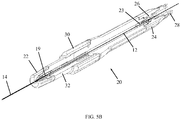
- FIG. 5A and 5B illustrate a steering tool with a manipulation handle 20, constructed and operative in accordance with a non-limiting example of the present invention.
- the proximal end 19 of the external tube 14 is affixed or locked in an external tube holder 22 at the distal end of the handle 20.
- the internal tube 12 is disposed in external tube 14 as described above.
- the internal tube 12 extends through the length of handle 20, and a proximal portion 23 of internal tube 12 may be held by a proximal internal tube holder 24.
- the internal tube holder 24 includes a septum 26 which is used to seal passage of the internal tube 12 therethrough.
- the handle 20 may be provided with a proximal fluid connector 28.
- the handle 20 is provided with a tube manipulator 30, such as a linear slider, for causing relative axial movement of the internal and external tubes.
- the tube manipulator 30 may abut against or be connected to a movable portion 32 of handle 20, which is connected to or abuts against the external tube holder 22.
- the movable portion 32 By moving tube manipulator 30 distally, the movable portion 32 also moves distally and causes the internal tube 12 to move distally as well, thereby causing bending of the distal tip of the internal and external tubes, as described above.
- the tube manipulator 30 may abut proximally against a stationary portion of the handle 20 and/or may "click" into a groove formed in the handle, which serves as a proximal stop and locks the tube manipulator 30 in place.
- the tube manipulator 30 may be released when desired from the locked position and relocked in place.
- the steering tool can be used very easily as a guide wire for
Landscapes
- Health & Medical Sciences (AREA)
- Life Sciences & Earth Sciences (AREA)
- Veterinary Medicine (AREA)
- Animal Behavior & Ethology (AREA)
- Engineering & Computer Science (AREA)
- Public Health (AREA)
- Biomedical Technology (AREA)
- Heart & Thoracic Surgery (AREA)
- General Health & Medical Sciences (AREA)
- Pulmonology (AREA)
- Hematology (AREA)
- Anesthesiology (AREA)
- Biophysics (AREA)
- Surgery (AREA)
- Nuclear Medicine, Radiotherapy & Molecular Imaging (AREA)
- Medical Informatics (AREA)
- Molecular Biology (AREA)
- Media Introduction/Drainage Providing Device (AREA)
Description
- The present invention generally relates to a steering tool for steering medical devices through body lumens.
- PCT Patent Application
PCT/us2013/040691 published asWO 2013/ 173197 , to the present inventor describes a steering tool for steering medical devices through body lumens. The steering tool has an internal tube disposed inside an external tube. The internal and external tubes are arranged for longitudinal axial movement relative to one another. The distal end of the internal tube is fixedly joined to the distal end of the external tube. One or both of the internal and external tubes is slotted near the distal end thereof. The longitudinal axial movement causes bending of the distal ends of the tubes. One or both of the internal and external tubes are slotted near the distal ends thereof. The steering tool provides a distal tip which combines steerability, flexibility and torqueability. The tool eliminates the need for pull/push wires. - Some of the advantages of that steering tool include reduced cross section, circular cross section in each direction for uniform stability of bending in different directions (towards two or more sides), very thin wall thickness, and applicability to very small tubes (e.g., diameters of 0.2-3 mm). The steering tool also works well with larger tubes. The steering tool simplifies production and reduces the number of parts for any steerable endoscope in medical and industrial fields.
- From
WO 93/14690 A1 US 5454787 there is known another steering tool. FromEP 1927375 A2 there is known a steering tool in the form of a catheter steering mechanism. - The present invention seeks to provide further improvements to the steering tool for steering medical devices through body lumens, as is described more in detail hereinbelow.
- There is thus provided in accordance with the present invention a system of a steering tool and a handle according to claim 1. Preferred developments are recited in the subclaims.
- In accordance with an embodiment of the present invention both of the internal and external tubes are slotted near the distal ends thereof.
- In accordance with an embodiment of the present invention shapes of the slots change as a parameter of distance from the distal ends of the internal and external tubes.
- In accordance with an embodiment of the present invention the internal and external tubes are each formed with one or more alignment holes for correct axial and rotational alignment of the internal and external tubes during joining and assembly.
- In accordance with an embodiment of the present invention an alignment pin is inserted in the one or more alignment holes.
- In accordance with an embodiment of the present invention an open-ended axial slot is formed in at least one of the internal and external tubes. The axial slot may be open to the most distal slot of the transverse slots.
- In accordance with an embodiment of the present invention the transverse slots decrease in length and width with increased distance from the distal ends of the internal and external tubes.
- The slots limit the amount of possible tube bending to avoid damage to the tubes. For example, the outer slots protect while pushing and the internal slots protect while pulling the internal tube.
- The present invention will be understood and appreciated more fully from the following detailed description taken in conjunction with the drawings in which:
-
Fig. 1 is a simplified illustration of a steering tool, in accordance with a non-limiting example of the present invention, showing one of the tubes of the steering tool in a spread-out view; -
Fig. 2 is a simplified illustration of the steering tool, in accordance with a non-limiting example of the present invention, showing internal and external tubes which are slotted; -
Fig. 3 is a simplified illustration of the steering tool, showing an alignment pin for proper alignment of the tubes during assembly; -
Fig. 4 is a simplified illustration of the steering tool with the internal part being a hollow tube with no slots or a conduit for fluid or wires for energy delivery or optic fiber to transfer optic data or laser; and -
Figs. 5A and5B are simplified pictorial and cutaway illustrations, respectively, of a steering tool with a manipulation handle, constructed and operative in accordance with a non-limiting example of the present invention. - Reference is now made to
Figs. 2 and3 , which illustrate asteering tool 10, in accordance with a non-limiting example of the present invention. -
Steering tool 10 includes aninternal tube 12 disposed inside anexternal tube 14. Adistal end 12D ofinternal tube 12 is fixedly joined to adistal end 14D ofexternal tube 14. The term "joined" encompasses any method for attaching the materials of the tubes together, such as but not limited to, welding, ultrasonic welding, thermal bonding, adhesive bonding, molding, and others. The internal andexternal tubes - In accordance with an example of the present invention,
internal tube 12 andexternal tube 14 are each formed with one ormore alignment holes 13 for correct alignment (including axial and rotational alignment about the longitudinal axis) of the tubes during joining and assembly. An alignment pin 15 (Fig. 3 ) may be inserted inalignment holes 13 to hold the tubes in the proper alignment during joining. Thealignment holes 13 may be off-center and/or of two different diameters to ensure that the tubes are not accidentally aligned incorrectly. - The outer diameter of
internal tube 12 is smaller than the inner diameter ofexternal tube 14 so they can easily slide relative to each other. This difference in diameter may pose a problem during welding or other types of joining. In accordance with an example of the present invention, in order to achieve good joining (e.g., welding or bonding) between the tubes despite the difference in diameters, an open-endedaxial slot 17 is formed ininternal tube 12 and/orexternal tube 14.Slot 17 provides a path for welding, soldering or adhesive material to flow and join the tubes together. - Internal and
external tubes - At least one of the internal and
external tubes slots 16 near the distal end thereof (e.g., transverse to the longitudinal axis of the tubes; the term transverse encompassing any angle - not just perpendicular - which is not parallel to the longitudinal axis of the tubes). In the example both tubes are slotted, but alternatively only one of the internal and external tubes is slotted and the other may be flexible but not slotted. The longitudinal axial movement causes bending of the distal ends of the tubes (on account of them being joined together), as is known fromPCT/US2013/040691 published asWO 2013/173197 . One of the internal and external tubes can be longer than the other (e.g., the internal one is longer for grasping its proximal end for pushing and pulling thereof). -
Slots 16 increase the flexibility toward the distal end of the tube or tubes for steerability of the device and controlled manipulation thereof. The amount of flexibility can be controlled by the number of slots, spacing therebetween, shape of the slot, angle subtended by the slot, thickness of the tube, material of the tube, and other factors.Slots 16 may subtend an arc of about 180-270°. - For example, as seen in
Fig. 1 , the shapes ofslots 16 change as a parameter of distance from the distal end. In the illustrated example, the slots decrease in length and width (e.g., asymptotically to a minimum size) with increased distance from the distal end. In this manner, the bending radius remains basically constant at any distance from the distal end and the bending moment increases with increased distance from the distal end.Axial slot 17 may be open to the mostdistal slot 16. - The
steering tool 10 may be covered with a semi-rigid or flexible sheath 18 (shown partially in broken lines inFig. 2 ) and used as a catheter or needle. In a more preferred example, shown inFig. 4 , theinternal tube 12 is a simple tube or wire with no slots. In the case of a hollow tube, theinternal tube 12 can serve as the conduit for delivery of fluids, light, laser, optic, cameras, illumination, electrical energy transfer (e.g., wired connections), and others, in addition to the mechanical function of bending, Thus, the device can be used to deliver fluids to places in a body with high accuracy, such as but not limited to, direct injection of drugs into the brain. For example,tool 10 may be used as a needle to protrude through or into a blood vessel and inject substances directly into the brain, tumor or infected area. Thesteering tool 10 may be used as a catheter to direct and deliver cooled gas to freeze tumors or other areas. Thesteering tool 10 may be used as a catheter to guide fiber optic or laser devices for illumination, treatment, ablation or drying or other uses. In another example, the fiber optic can be part of the mechanical steering system, serving as a pull wire inside the internal or external tube. In this manner, a controlled fiber optic with a diameter of 0.3 mm becomes feasible. - In any of the examples, the distal edge shape of the internal tube, external tube and/or overall tool may be not only circular, but also shaped as an electrode, needle or
- Reference is now made to
Figs. 5A and5B , which illustrate a steering tool with amanipulation handle 20, constructed and operative in accordance with a non-limiting example of the present invention. - In this steering tool, the
proximal end 19 of theexternal tube 14 is affixed or locked in anexternal tube holder 22 at the distal end of thehandle 20. Theinternal tube 12 is disposed inexternal tube 14 as described above. Theinternal tube 12 extends through the length ofhandle 20, and aproximal portion 23 ofinternal tube 12 may be held by a proximalinternal tube holder 24. Theinternal tube holder 24 includes aseptum 26 which is used to seal passage of theinternal tube 12 therethrough. Thehandle 20 may be provided with aproximal fluid connector 28. - The
handle 20 is provided with atube manipulator 30, such as a linear slider, for causing relative axial movement of the internal and external tubes. For example, thetube manipulator 30 may abut against or be connected to amovable portion 32 ofhandle 20, which is connected to or abuts against theexternal tube holder 22. By movingtube manipulator 30 distally, themovable portion 32 also moves distally and causes theinternal tube 12 to move distally as well, thereby causing bending of the distal tip of the internal and external tubes, as described above. Thetube manipulator 30 may abut proximally against a stationary portion of thehandle 20 and/or may "click" into a groove formed in the handle, which serves as a proximal stop and locks thetube manipulator 30 in place. Thetube manipulator 30 may be released when desired from the locked position and relocked in place. Thus, the steering tool can be used very easily as a guide wire for
Claims (8)
- A system of a steering tool (10) and a handle (20) comprising:an internal tube (12) disposed inside an external tube (14), said internal and external tubes (12, 14) being arranged for longitudinal axial movement relative to one another, wherein a distal end of said internal tube (12) is fixedly joined to a distal end of said external tube (14), and at least one of said internal and external tubes (12, 14) is formed with transverse slots (16) near the distal end thereof, and wherein the longitudinal axial movement causes bending of the distal ends of said tubes;and wherein shapes of said slots (16) change as a parameter of distance from the distal ends of said internal and external tubes (12, 14);
a proximal end of said external tube (14) is affixed or locked in an external tube holder (22) at a distal end of the handle (20) and said internal tube (12) extends through said handle (20);
and wherein said handle (20) comprises a tube manipulator (30) operative to cause relative axial movement of said internal and external tubes (12, 14);
characterized in that a proximal portion of said internal tube (12) being held by a proximal internal tube holder (24), and wherein said internal tube holder (24) comprises a septum (26) that seals the passage of said internal tube (12) therethrough. - The system according to claim 1, wherein said handle (20) comprises a proximal fluid connector (28).
- The system according to claim 1, wherein said transverse slots (16) decrease in length and width with increased distance from the distal ends of said internal and external tubes (12, 14).
- The system according to claim 3, wherein said transverse slots (16) decrease in length and width asymptotically to a minimum size.
- The system according to claim 1, wherein said steering tool (10) is covered with a semi-rigid or flexible sheath (18).
- The system according to claim 1, wherein both of said internal and external tubes (12, 14) are slotted near the distal ends thereof.
- The system according to claim 1, wherein said tube manipulator (30) is arranged to abut against or be connected to a movable portion of said handle (20), said movable portion being connected to or abutting against said external tube holder (22), and wherein distal movement of said tube manipulator (30) causes said movable portion to move distally and cause said internal tube (12) to move distally to cause bending of distal tips of said internal and said external tubes (12, 14).
- The system according to claim 1, wherein said tube manipulator (30) is arranged to abut proximally against a stationary portion of said handle (20) and to be removably received in a proximal stop formed in said handle (20).
Applications Claiming Priority (2)
| Application Number | Priority Date | Filing Date | Title |
|---|---|---|---|
| US14/044,886 US20150099997A1 (en) | 2013-10-03 | 2013-10-03 | Steering tool |
| PCT/US2014/058743 WO2015051070A1 (en) | 2013-10-03 | 2014-10-02 | Steering tool |
Publications (2)
| Publication Number | Publication Date |
|---|---|
| EP3052175A1 EP3052175A1 (en) | 2016-08-10 |
| EP3052175B1 true EP3052175B1 (en) | 2017-11-22 |
Family
ID=51842820
Family Applications (1)
| Application Number | Title | Priority Date | Filing Date |
|---|---|---|---|
| EP14790874.3A Active EP3052175B1 (en) | 2013-10-03 | 2014-10-02 | System of a steering tool and a handle |
Country Status (4)
| Country | Link |
|---|---|
| US (3) | US20150099997A1 (en) |
| EP (1) | EP3052175B1 (en) |
| CN (1) | CN105792876B (en) |
| WO (1) | WO2015051070A1 (en) |
Families Citing this family (53)
| Publication number | Priority date | Publication date | Assignee | Title |
|---|---|---|---|---|
| US12220538B2 (en) | 2008-12-08 | 2025-02-11 | Scientia Vascular, Inc. | Micro-fabricated intravascular devices having varying diameters |
| US20100298832A1 (en) | 2009-05-20 | 2010-11-25 | Osseon Therapeutics, Inc. | Steerable curvable vertebroplasty drill |
| US9339271B2 (en) | 2013-03-14 | 2016-05-17 | C.R. Bard, Inc. | Articulating surgical instruments |
| US9839765B2 (en) * | 2013-11-12 | 2017-12-12 | St. Jude Medical, Cardiology Division, Inc. | Transfemoral mitral valve repair delivery device |
| ES2751493T3 (en) | 2014-12-05 | 2020-03-31 | Fortimedix Surgical B V | Method for making a steerable instrument and said steerable instrument |
| US9901392B2 (en) * | 2015-05-11 | 2018-02-27 | Dfine, Inc. | System for use in treatment of vertebral fractures |
| US12465339B2 (en) * | 2016-03-01 | 2025-11-11 | Bendit Technologies Ltd. | Steering tool with controlled distal flexibility |
| NL2016900B1 (en) | 2016-06-06 | 2017-12-13 | Fortimedix Surgical B V | Steerable instrument comprising a cylindrical diameter adaptation section |
| US10391274B2 (en) | 2016-07-07 | 2019-08-27 | Brian Giles | Medical device with distal torque control |
| US9918705B2 (en) | 2016-07-07 | 2018-03-20 | Brian Giles | Medical devices with distal control |
| US11207502B2 (en) | 2016-07-18 | 2021-12-28 | Scientia Vascular, Llc | Guidewire devices having shapeable tips and bypass cuts |
| CN109789017B (en) * | 2016-08-19 | 2022-05-31 | 爱德华兹生命科学公司 | Steerable delivery system for replacing a mitral valve and methods of use |
| CN107837105B (en) * | 2016-09-18 | 2020-09-01 | 先健科技(深圳)有限公司 | Puncture catheters and tissue tightening systems |
| CN109862834B (en) | 2016-10-27 | 2022-05-24 | Dfine有限公司 | Bendable osteotome with cement delivery channel |
| US11141566B2 (en) * | 2016-11-06 | 2021-10-12 | Bendit Technologies Ltd. | Steering tool |
| WO2018098433A1 (en) | 2016-11-28 | 2018-05-31 | Dfine, Inc. | Tumor ablation devices and related methods |
| US10463380B2 (en) | 2016-12-09 | 2019-11-05 | Dfine, Inc. | Medical devices for treating hard tissues and related methods |
| WO2018129180A1 (en) | 2017-01-06 | 2018-07-12 | Dfine, Inc. | Osteotome with a distal portion for simultaneous advancement and articulation |
| EP4257173A3 (en) | 2017-05-26 | 2023-11-29 | Scientia Vascular, Inc. | Micro-fabricated medical device having a non-helical cut arrangement |
| NL2019175B1 (en) | 2017-07-04 | 2019-01-14 | Fortimedix Surgical B V | Steerable instrument comprising a radial spacers between coaxial cylindrical elements |
| US11116509B2 (en) | 2017-11-10 | 2021-09-14 | Avantec Vascular Corporation | System and method for delivering an embolic device |
| US11134928B2 (en) | 2018-01-10 | 2021-10-05 | C.R. Bard, Inc. | Articulating surgical instruments |
| US10779813B2 (en) | 2018-01-10 | 2020-09-22 | C.R. Bard, Inc. | Articulating surgical instruments |
| US11103234B2 (en) | 2018-01-10 | 2021-08-31 | C.R. Bard, Inc. | Articulating surgical instruments |
| WO2019147846A2 (en) | 2018-01-25 | 2019-08-01 | Edwards Lifesciences Corporation | Delivery system for aided replacement valve recapture and repositioning post- deployment |
| US10456556B2 (en) * | 2018-02-19 | 2019-10-29 | Bendit Technologies Ltd. | Steering tool with enhanced flexibility and trackability |
| US11583168B2 (en) * | 2018-11-08 | 2023-02-21 | Thomas J. Viren | Endotracheal tube system and method |
| US12011555B2 (en) | 2019-01-15 | 2024-06-18 | Scientia Vascular, Inc. | Guidewire with core centering mechanism |
| CN113873955B (en) | 2019-04-01 | 2024-10-25 | 富通麦迪资产二有限公司 | Steerable device including a hinge with a slotted structure |
| KR20210149102A (en) | 2019-04-08 | 2021-12-08 | 포티메딕스 에셋츠 Ii 비.브이. | A steerable mechanism comprising a removable portion |
| US12582300B2 (en) | 2019-04-08 | 2026-03-24 | Fortimedix Assets Ii B.V. | Steerable instrument comprising a detachable part |
| US12623049B2 (en) | 2019-05-02 | 2026-05-12 | Scientia Vascular, Inc. | Intravascular device with enhanced one-beam cut pattern |
| US12585201B2 (en) | 2019-10-14 | 2026-03-24 | Asml Holding N.V. | Metrology mark structure and method of determining metrology mark structure |
| US11382634B2 (en) | 2019-12-18 | 2022-07-12 | Avantec Vascular Corporation | Embolic device suited for ease of delivery and placement |
| US11969280B2 (en) | 2020-01-07 | 2024-04-30 | Cleerly, Inc. | Systems, methods, and devices for medical image analysis, diagnosis, risk stratification, decision making and/or disease tracking |
| US20220392065A1 (en) | 2020-01-07 | 2022-12-08 | Cleerly, Inc. | Systems, methods, and devices for medical image analysis, diagnosis, risk stratification, decision making and/or disease tracking |
| CA3162872A1 (en) | 2020-01-07 | 2021-07-15 | James K. MIN | Systems, methods, and devices for medical image analysis, diagnosis, risk stratification, decision making and/or disease tracking |
| US12178975B2 (en) | 2020-01-23 | 2024-12-31 | Scientia Vascular, Inc. | Guidewire having enlarged, micro-fabricated distal section |
| US12343485B2 (en) | 2020-01-23 | 2025-07-01 | Scientia Vascular, Inc. | High torque guidewire device |
| WO2021228099A1 (en) * | 2020-05-11 | 2021-11-18 | Shanghai Newmed Medical Co., Ltd. | Delivery pipes, guide pipes and tissue repair devices |
| CN111973864B (en) * | 2020-08-31 | 2021-07-23 | 尚华 | Optical function guide wire, detection system and detection method |
| CN111973865A (en) * | 2020-08-31 | 2020-11-24 | 尚华 | Optical fiber guide wire, optical fiber guide wire detection system and method |
| US12296112B2 (en) | 2020-10-05 | 2025-05-13 | Scientia Vascular, Inc. | Microfabricated catheter devices with high axial strength |
| JP7840987B2 (en) | 2021-10-05 | 2026-04-06 | シーメンス ヘルシニアーズ エンドバスキュラー ロボティクス インコーポレイテッド | Robot control of slender medical devices |
| US12440180B2 (en) | 2022-03-10 | 2025-10-14 | Cleerly, Inc. | Systems, devices, and methods for non-invasive image-based plaque analysis and risk determination |
| US12406365B2 (en) | 2022-03-10 | 2025-09-02 | Cleerly, Inc. | Systems, devices, and methods for non-invasive image-based plaque analysis and risk determination |
| US20250143657A1 (en) | 2022-03-10 | 2025-05-08 | Cleerly, Inc. | Systems, devices, and methods for non-invasive image-based plaque analysis and risk determination |
| US20250217981A1 (en) | 2022-03-10 | 2025-07-03 | Cleerly, Inc. | Systems, methods, and devices for image-based plaque analysis and risk determination |
| EP4568730A1 (en) | 2022-08-11 | 2025-06-18 | Petrus Antonius Besselink | Flexible and steerable device with adjustable floppiness |
| CN115415436B (en) * | 2022-09-27 | 2025-04-15 | 丹源医学科技(杭州)有限公司 | A controllable bending shaping device for electrode wire |
| CN119701170B (en) * | 2023-09-27 | 2026-01-23 | 上海拓脉医疗科技有限公司 | Medical catheter |
| WO2025090802A1 (en) * | 2023-10-27 | 2025-05-01 | SmartAirway LLC | Articulating stylet |
| CN121796788A (en) * | 2026-03-06 | 2026-04-07 | 上海微密医疗科技有限公司 | Interventional therapy conveying device |
Family Cites Families (13)
| Publication number | Priority date | Publication date | Assignee | Title |
|---|---|---|---|---|
| US3802440A (en) * | 1972-12-19 | 1974-04-09 | M Salem | Intubation guide |
| US3996939A (en) * | 1975-07-22 | 1976-12-14 | National Catheter Corporation | Intubation stylets |
| JPH0358402U (en) * | 1989-10-13 | 1991-06-06 | ||
| US5454787A (en) * | 1991-02-15 | 1995-10-03 | Lundquist; Ingemar H. | Torquable tubular assembly and torquable catheter utilizing the same |
| US5284128A (en) * | 1992-01-24 | 1994-02-08 | Applied Medical Resources Corporation | Surgical manipulator |
| JP4096325B2 (en) * | 1998-12-14 | 2008-06-04 | 正喜 江刺 | Active capillary and method for manufacturing the same |
| US20050256452A1 (en) * | 2002-11-15 | 2005-11-17 | Demarchi Thomas | Steerable vascular sheath |
| US7001369B2 (en) * | 2003-03-27 | 2006-02-21 | Scimed Life Systems, Inc. | Medical device |
| US20090281498A1 (en) * | 2006-04-19 | 2009-11-12 | Acosta Pablo G | Devices, system and methods for minimally invasive abdominal surgical procedures |
| AU2007231733B2 (en) * | 2006-11-28 | 2014-03-13 | Cathrx Ltd | A catheter steering system |
| US8920369B2 (en) * | 2009-06-24 | 2014-12-30 | Shifamed Holdings, Llc | Steerable delivery sheaths |
| AU2010266027B2 (en) * | 2009-06-24 | 2015-05-07 | Shifamed Holdings, Llc | Steerable medical delivery devices and methods of use |
| US8684953B2 (en) * | 2012-05-13 | 2014-04-01 | Ozca Engineering Solutions Ltd. | Steering tool |
-
2013
- 2013-10-03 US US14/044,886 patent/US20150099997A1/en not_active Abandoned
-
2014
- 2014-10-02 EP EP14790874.3A patent/EP3052175B1/en active Active
- 2014-10-02 WO PCT/US2014/058743 patent/WO2015051070A1/en not_active Ceased
- 2014-10-02 CN CN201480063577.5A patent/CN105792876B/en active Active
-
2020
- 2020-05-27 US US16/884,173 patent/US20200282181A1/en not_active Abandoned
-
2023
- 2023-09-01 US US18/459,441 patent/US12397133B2/en active Active
Also Published As
| Publication number | Publication date |
|---|---|
| US20150099997A1 (en) | 2015-04-09 |
| US20200282181A1 (en) | 2020-09-10 |
| US12397133B2 (en) | 2025-08-26 |
| CN105792876B (en) | 2020-06-16 |
| CN105792876A (en) | 2016-07-20 |
| US20230405276A1 (en) | 2023-12-21 |
| EP3052175A1 (en) | 2016-08-10 |
| WO2015051070A1 (en) | 2015-04-09 |
Similar Documents
| Publication | Publication Date | Title |
|---|---|---|
| US12397133B2 (en) | Steering tool | |
| EP3082932B1 (en) | Steering tool | |
| CN110035791B (en) | Operating tool | |
| JP4152546B2 (en) | Bi-directional electrode catheter | |
| EP2849653B1 (en) | Steering tool | |
| US10492876B2 (en) | Devices and methods for laser surgery | |
| US8684953B2 (en) | Steering tool | |
| US9919131B2 (en) | Magnetically guided catheter with concentric needle port | |
| JP2017531544A5 (en) | ||
| CN102665573A (en) | Devices, methods, and kits for forming tracts in tissue | |
| CN111973865A (en) | Optical fiber guide wire, optical fiber guide wire detection system and method | |
| JP2014030718A (en) | Guide wire | |
| EP3209365B1 (en) | Centering coiled guide | |
| EP4729010A1 (en) | Metallic guide tube |
Legal Events
| Date | Code | Title | Description |
|---|---|---|---|
| PUAI | Public reference made under article 153(3) epc to a published international application that has entered the european phase |
Free format text: ORIGINAL CODE: 0009012 |
|
| 17P | Request for examination filed |
Effective date: 20160419 |
|
| AK | Designated contracting states |
Kind code of ref document: A1 Designated state(s): AL AT BE BG CH CY CZ DE DK EE ES FI FR GB GR HR HU IE IS IT LI LT LU LV MC MK MT NL NO PL PT RO RS SE SI SK SM TR |
|
| AX | Request for extension of the european patent |
Extension state: BA ME |
|
| RIN1 | Information on inventor provided before grant (corrected) |
Inventor name: CABIRI, OZ |
|
| DAX | Request for extension of the european patent (deleted) | ||
| STAA | Information on the status of an ep patent application or granted ep patent |
Free format text: STATUS: EXAMINATION IS IN PROGRESS |
|
| 17Q | First examination report despatched |
Effective date: 20170127 |
|
| GRAP | Despatch of communication of intention to grant a patent |
Free format text: ORIGINAL CODE: EPIDOSNIGR1 |
|
| STAA | Information on the status of an ep patent application or granted ep patent |
Free format text: STATUS: GRANT OF PATENT IS INTENDED |
|
| INTG | Intention to grant announced |
Effective date: 20170823 |
|
| GRAS | Grant fee paid |
Free format text: ORIGINAL CODE: EPIDOSNIGR3 |
|
| GRAA | (expected) grant |
Free format text: ORIGINAL CODE: 0009210 |
|
| STAA | Information on the status of an ep patent application or granted ep patent |
Free format text: STATUS: THE PATENT HAS BEEN GRANTED |
|
| AK | Designated contracting states |
Kind code of ref document: B1 Designated state(s): AL AT BE BG CH CY CZ DE DK EE ES FI FR GB GR HR HU IE IS IT LI LT LU LV MC MK MT NL NO PL PT RO RS SE SI SK SM TR |
|
| REG | Reference to a national code |
Ref country code: GB Ref legal event code: FG4D |
|
| REG | Reference to a national code |
Ref country code: CH Ref legal event code: EP |
|
| REG | Reference to a national code |
Ref country code: IE Ref legal event code: FG4D |
|
| REG | Reference to a national code |
Ref country code: AT Ref legal event code: REF Ref document number: 947843 Country of ref document: AT Kind code of ref document: T Effective date: 20171215 Ref country code: CH Ref legal event code: NV Representative=s name: ROMAN VUILLE, CH |
|
| REG | Reference to a national code |
Ref country code: DE Ref legal event code: R096 Ref document number: 602014017693 Country of ref document: DE |
|
| REG | Reference to a national code |
Ref country code: NL Ref legal event code: FP |
|
| REG | Reference to a national code |
Ref country code: LT Ref legal event code: MG4D |
|
| REG | Reference to a national code |
Ref country code: AT Ref legal event code: MK05 Ref document number: 947843 Country of ref document: AT Kind code of ref document: T Effective date: 20171122 |
|
| PG25 | Lapsed in a contracting state [announced via postgrant information from national office to epo] |
Ref country code: ES Free format text: LAPSE BECAUSE OF FAILURE TO SUBMIT A TRANSLATION OF THE DESCRIPTION OR TO PAY THE FEE WITHIN THE PRESCRIBED TIME-LIMIT Effective date: 20171122 Ref country code: FI Free format text: LAPSE BECAUSE OF FAILURE TO SUBMIT A TRANSLATION OF THE DESCRIPTION OR TO PAY THE FEE WITHIN THE PRESCRIBED TIME-LIMIT Effective date: 20171122 Ref country code: SE Free format text: LAPSE BECAUSE OF FAILURE TO SUBMIT A TRANSLATION OF THE DESCRIPTION OR TO PAY THE FEE WITHIN THE PRESCRIBED TIME-LIMIT Effective date: 20171122 Ref country code: NO Free format text: LAPSE BECAUSE OF FAILURE TO SUBMIT A TRANSLATION OF THE DESCRIPTION OR TO PAY THE FEE WITHIN THE PRESCRIBED TIME-LIMIT Effective date: 20180222 Ref country code: LT Free format text: LAPSE BECAUSE OF FAILURE TO SUBMIT A TRANSLATION OF THE DESCRIPTION OR TO PAY THE FEE WITHIN THE PRESCRIBED TIME-LIMIT Effective date: 20171122 |
|
| PG25 | Lapsed in a contracting state [announced via postgrant information from national office to epo] |
Ref country code: BG Free format text: LAPSE BECAUSE OF FAILURE TO SUBMIT A TRANSLATION OF THE DESCRIPTION OR TO PAY THE FEE WITHIN THE PRESCRIBED TIME-LIMIT Effective date: 20180222 Ref country code: LV Free format text: LAPSE BECAUSE OF FAILURE TO SUBMIT A TRANSLATION OF THE DESCRIPTION OR TO PAY THE FEE WITHIN THE PRESCRIBED TIME-LIMIT Effective date: 20171122 Ref country code: RS Free format text: LAPSE BECAUSE OF FAILURE TO SUBMIT A TRANSLATION OF THE DESCRIPTION OR TO PAY THE FEE WITHIN THE PRESCRIBED TIME-LIMIT Effective date: 20171122 Ref country code: GR Free format text: LAPSE BECAUSE OF FAILURE TO SUBMIT A TRANSLATION OF THE DESCRIPTION OR TO PAY THE FEE WITHIN THE PRESCRIBED TIME-LIMIT Effective date: 20180223 Ref country code: AT Free format text: LAPSE BECAUSE OF FAILURE TO SUBMIT A TRANSLATION OF THE DESCRIPTION OR TO PAY THE FEE WITHIN THE PRESCRIBED TIME-LIMIT Effective date: 20171122 Ref country code: HR Free format text: LAPSE BECAUSE OF FAILURE TO SUBMIT A TRANSLATION OF THE DESCRIPTION OR TO PAY THE FEE WITHIN THE PRESCRIBED TIME-LIMIT Effective date: 20171122 |
|
| PG25 | Lapsed in a contracting state [announced via postgrant information from national office to epo] |
Ref country code: CZ Free format text: LAPSE BECAUSE OF FAILURE TO SUBMIT A TRANSLATION OF THE DESCRIPTION OR TO PAY THE FEE WITHIN THE PRESCRIBED TIME-LIMIT Effective date: 20171122 Ref country code: EE Free format text: LAPSE BECAUSE OF FAILURE TO SUBMIT A TRANSLATION OF THE DESCRIPTION OR TO PAY THE FEE WITHIN THE PRESCRIBED TIME-LIMIT Effective date: 20171122 Ref country code: CY Free format text: LAPSE BECAUSE OF FAILURE TO SUBMIT A TRANSLATION OF THE DESCRIPTION OR TO PAY THE FEE WITHIN THE PRESCRIBED TIME-LIMIT Effective date: 20171122 Ref country code: DK Free format text: LAPSE BECAUSE OF FAILURE TO SUBMIT A TRANSLATION OF THE DESCRIPTION OR TO PAY THE FEE WITHIN THE PRESCRIBED TIME-LIMIT Effective date: 20171122 Ref country code: SK Free format text: LAPSE BECAUSE OF FAILURE TO SUBMIT A TRANSLATION OF THE DESCRIPTION OR TO PAY THE FEE WITHIN THE PRESCRIBED TIME-LIMIT Effective date: 20171122 |
|
| REG | Reference to a national code |
Ref country code: DE Ref legal event code: R097 Ref document number: 602014017693 Country of ref document: DE |
|
| PG25 | Lapsed in a contracting state [announced via postgrant information from national office to epo] |
Ref country code: RO Free format text: LAPSE BECAUSE OF FAILURE TO SUBMIT A TRANSLATION OF THE DESCRIPTION OR TO PAY THE FEE WITHIN THE PRESCRIBED TIME-LIMIT Effective date: 20171122 Ref country code: SM Free format text: LAPSE BECAUSE OF FAILURE TO SUBMIT A TRANSLATION OF THE DESCRIPTION OR TO PAY THE FEE WITHIN THE PRESCRIBED TIME-LIMIT Effective date: 20171122 Ref country code: PL Free format text: LAPSE BECAUSE OF FAILURE TO SUBMIT A TRANSLATION OF THE DESCRIPTION OR TO PAY THE FEE WITHIN THE PRESCRIBED TIME-LIMIT Effective date: 20171122 |
|
| PLBE | No opposition filed within time limit |
Free format text: ORIGINAL CODE: 0009261 |
|
| STAA | Information on the status of an ep patent application or granted ep patent |
Free format text: STATUS: NO OPPOSITION FILED WITHIN TIME LIMIT |
|
| REG | Reference to a national code |
Ref country code: FR Ref legal event code: PLFP Year of fee payment: 5 |
|
| 26N | No opposition filed |
Effective date: 20180823 |
|
| PG25 | Lapsed in a contracting state [announced via postgrant information from national office to epo] |
Ref country code: SI Free format text: LAPSE BECAUSE OF FAILURE TO SUBMIT A TRANSLATION OF THE DESCRIPTION OR TO PAY THE FEE WITHIN THE PRESCRIBED TIME-LIMIT Effective date: 20171122 |
|
| REG | Reference to a national code |
Ref country code: BE Ref legal event code: MM Effective date: 20181031 |
|
| PG25 | Lapsed in a contracting state [announced via postgrant information from national office to epo] |
Ref country code: MC Free format text: LAPSE BECAUSE OF FAILURE TO SUBMIT A TRANSLATION OF THE DESCRIPTION OR TO PAY THE FEE WITHIN THE PRESCRIBED TIME-LIMIT Effective date: 20171122 Ref country code: LU Free format text: LAPSE BECAUSE OF NON-PAYMENT OF DUE FEES Effective date: 20181002 |
|
| PG25 | Lapsed in a contracting state [announced via postgrant information from national office to epo] |
Ref country code: BE Free format text: LAPSE BECAUSE OF NON-PAYMENT OF DUE FEES Effective date: 20181031 |
|
| PG25 | Lapsed in a contracting state [announced via postgrant information from national office to epo] |
Ref country code: MT Free format text: LAPSE BECAUSE OF NON-PAYMENT OF DUE FEES Effective date: 20181002 |
|
| PG25 | Lapsed in a contracting state [announced via postgrant information from national office to epo] |
Ref country code: PT Free format text: LAPSE BECAUSE OF FAILURE TO SUBMIT A TRANSLATION OF THE DESCRIPTION OR TO PAY THE FEE WITHIN THE PRESCRIBED TIME-LIMIT Effective date: 20171122 |
|
| PG25 | Lapsed in a contracting state [announced via postgrant information from national office to epo] |
Ref country code: MK Free format text: LAPSE BECAUSE OF NON-PAYMENT OF DUE FEES Effective date: 20171122 Ref country code: HU Free format text: LAPSE BECAUSE OF FAILURE TO SUBMIT A TRANSLATION OF THE DESCRIPTION OR TO PAY THE FEE WITHIN THE PRESCRIBED TIME-LIMIT; INVALID AB INITIO Effective date: 20141002 |
|
| PG25 | Lapsed in a contracting state [announced via postgrant information from national office to epo] |
Ref country code: AL Free format text: LAPSE BECAUSE OF FAILURE TO SUBMIT A TRANSLATION OF THE DESCRIPTION OR TO PAY THE FEE WITHIN THE PRESCRIBED TIME-LIMIT Effective date: 20171122 Ref country code: IS Free format text: LAPSE BECAUSE OF FAILURE TO SUBMIT A TRANSLATION OF THE DESCRIPTION OR TO PAY THE FEE WITHIN THE PRESCRIBED TIME-LIMIT Effective date: 20180322 |
|
| REG | Reference to a national code |
Ref country code: CH Ref legal event code: U11 Free format text: ST27 STATUS EVENT CODE: U-0-0-U10-U11 (AS PROVIDED BY THE NATIONAL OFFICE) Effective date: 20251101 |
|
| PGFP | Annual fee paid to national office [announced via postgrant information from national office to epo] |
Ref country code: NL Payment date: 20251023 Year of fee payment: 12 |
|
| PGFP | Annual fee paid to national office [announced via postgrant information from national office to epo] |
Ref country code: DE Payment date: 20251008 Year of fee payment: 12 |
|
| PGFP | Annual fee paid to national office [announced via postgrant information from national office to epo] |
Ref country code: GB Payment date: 20251024 Year of fee payment: 12 |
|
| PGFP | Annual fee paid to national office [announced via postgrant information from national office to epo] |
Ref country code: IT Payment date: 20251031 Year of fee payment: 12 |
|
| PGFP | Annual fee paid to national office [announced via postgrant information from national office to epo] |
Ref country code: FR Payment date: 20251029 Year of fee payment: 12 |
|
| PGFP | Annual fee paid to national office [announced via postgrant information from national office to epo] |
Ref country code: TR Payment date: 20251024 Year of fee payment: 12 |
|
| PGFP | Annual fee paid to national office [announced via postgrant information from national office to epo] |
Ref country code: CH Payment date: 20251101 Year of fee payment: 12 |
|
| PGFP | Annual fee paid to national office [announced via postgrant information from national office to epo] |
Ref country code: IE Payment date: 20251021 Year of fee payment: 12 |