EP3052042B1 - System for interacting with an object - Google Patents
System for interacting with an object Download PDFInfo
- Publication number
- EP3052042B1 EP3052042B1 EP14790423.9A EP14790423A EP3052042B1 EP 3052042 B1 EP3052042 B1 EP 3052042B1 EP 14790423 A EP14790423 A EP 14790423A EP 3052042 B1 EP3052042 B1 EP 3052042B1
- Authority
- EP
- European Patent Office
- Prior art keywords
- tool
- position control
- frequency
- control mode
- frequencies
- Prior art date
- Legal status (The legal status is an assumption and is not a legal conclusion. Google has not performed a legal analysis and makes no representation as to the accuracy of the status listed.)
- Active
Links
- 230000009466 transformation Effects 0.000 description 36
- 238000000034 method Methods 0.000 description 24
- 230000004044 response Effects 0.000 description 17
- 230000003287 optical effect Effects 0.000 description 15
- 239000011159 matrix material Substances 0.000 description 14
- 210000003484 anatomy Anatomy 0.000 description 12
- 238000001356 surgical procedure Methods 0.000 description 10
- 238000005520 cutting process Methods 0.000 description 6
- 230000007423 decrease Effects 0.000 description 5
- 230000008901 benefit Effects 0.000 description 4
- 230000004807 localization Effects 0.000 description 4
- 210000002303 tibia Anatomy 0.000 description 4
- 210000001519 tissue Anatomy 0.000 description 4
- 210000000689 upper leg Anatomy 0.000 description 4
- 238000005452 bending Methods 0.000 description 3
- 238000001444 catalytic combustion detection Methods 0.000 description 3
- 238000004891 communication Methods 0.000 description 3
- 238000005070 sampling Methods 0.000 description 3
- 238000002679 ablation Methods 0.000 description 2
- 230000001133 acceleration Effects 0.000 description 2
- 210000000988 bone and bone Anatomy 0.000 description 2
- 210000004417 patella Anatomy 0.000 description 2
- 230000000737 periodic effect Effects 0.000 description 2
- 230000035484 reaction time Effects 0.000 description 2
- 230000008859 change Effects 0.000 description 1
- 238000002591 computed tomography Methods 0.000 description 1
- 230000003247 decreasing effect Effects 0.000 description 1
- 230000001419 dependent effect Effects 0.000 description 1
- 238000001514 detection method Methods 0.000 description 1
- 230000004069 differentiation Effects 0.000 description 1
- 239000012636 effector Substances 0.000 description 1
- 230000010354 integration Effects 0.000 description 1
- 238000004519 manufacturing process Methods 0.000 description 1
- 239000000203 mixture Substances 0.000 description 1
- 238000002360 preparation method Methods 0.000 description 1
- 230000008569 process Effects 0.000 description 1
- 238000003860 storage Methods 0.000 description 1
Images


Classifications
-
- A—HUMAN NECESSITIES
- A61—MEDICAL OR VETERINARY SCIENCE; HYGIENE
- A61B—DIAGNOSIS; SURGERY; IDENTIFICATION
- A61B34/00—Computer-aided surgery; Manipulators or robots specially adapted for use in surgery
- A61B34/30—Surgical robots
-
- B—PERFORMING OPERATIONS; TRANSPORTING
- B25—HAND TOOLS; PORTABLE POWER-DRIVEN TOOLS; MANIPULATORS
- B25J—MANIPULATORS; CHAMBERS PROVIDED WITH MANIPULATION DEVICES
- B25J9/00—Programme-controlled manipulators
- B25J9/16—Programme controls
- B25J9/1628—Programme controls characterised by the control loop
- B25J9/1653—Programme controls characterised by the control loop parameters identification, estimation, stiffness, accuracy, error analysis
-
- A—HUMAN NECESSITIES
- A61—MEDICAL OR VETERINARY SCIENCE; HYGIENE
- A61B—DIAGNOSIS; SURGERY; IDENTIFICATION
- A61B34/00—Computer-aided surgery; Manipulators or robots specially adapted for use in surgery
- A61B34/20—Surgical navigation systems; Devices for tracking or guiding surgical instruments, e.g. for frameless stereotaxis
- A61B2034/2046—Tracking techniques
- A61B2034/2055—Optical tracking systems
-
- A—HUMAN NECESSITIES
- A61—MEDICAL OR VETERINARY SCIENCE; HYGIENE
- A61B—DIAGNOSIS; SURGERY; IDENTIFICATION
- A61B34/00—Computer-aided surgery; Manipulators or robots specially adapted for use in surgery
- A61B34/20—Surgical navigation systems; Devices for tracking or guiding surgical instruments, e.g. for frameless stereotaxis
- A61B2034/2046—Tracking techniques
- A61B2034/2059—Mechanical position encoders
-
- A—HUMAN NECESSITIES
- A61—MEDICAL OR VETERINARY SCIENCE; HYGIENE
- A61B—DIAGNOSIS; SURGERY; IDENTIFICATION
- A61B90/00—Instruments, implements or accessories specially adapted for surgery or diagnosis and not covered by any of the groups A61B1/00 - A61B50/00, e.g. for luxation treatment or for protecting wound edges
- A61B90/08—Accessories or related features not otherwise provided for
- A61B2090/0818—Redundant systems, e.g. using two independent measuring systems and comparing the signals
-
- G—PHYSICS
- G05—CONTROLLING; REGULATING
- G05B—CONTROL OR REGULATING SYSTEMS IN GENERAL; FUNCTIONAL ELEMENTS OF SUCH SYSTEMS; MONITORING OR TESTING ARRANGEMENTS FOR SUCH SYSTEMS OR ELEMENTS
- G05B2219/00—Program-control systems
- G05B2219/30—Nc systems
- G05B2219/45—Nc applications
- G05B2219/45117—Medical, radio surgery manipulator
Definitions
- the present invention relates generally to a system and method for interacting with an object, and more specifically, a system for controlling a tool that interacts with the object.
- the system typically includes a base with a plurality of linkages extending from the base.
- the system further includes a tool coupled to the plurality of linkages.
- the medical personnel may perform the surgical procedure with the system by providing instruction to the system to move the plurality of linkages and the tool with respect to the object.
- Navigation systems provide accurate position and orientation information for the tool and other objects being tracked, especially when these objects move within a relatively large working volume.
- the navigation-based position and orientation information is often provided to at least partially influence movement and positioning of the linkages of the system relative to a patient's anatomy of interest.
- movement of the tool can be controlled in an open loop fashion using position and orientation information derived from a plurality of encoders associated with the plurality of linkages.
- position and orientation information derived from a plurality of encoders associated with the plurality of linkages.
- encoders can provide more precision than the navigation system in a localized area of interest.
- encoder-based position and orientation information may be useful when there is a desire to operate at a faster rate outside of the closed loop control of the navigation system.
- the linkages exhibit a response frequency that is slower than the frequency at which the navigation-based position and orientation information is provided. More specifically, the linkages, motors, joints, etc. of most systems have some flexibility or play. This flexibility limits the reaction time between movement commands and ultimate movement and settling of the tool. If the position and orientation information from the navigation system is utilized for generating movement commands at a frequency faster than the tool is able to move and settle in reaction to such movement commands, the closed loop control of the system will become unstable. Additionally, the slow response frequency of the linkages inhibits the frequency at which this navigation-based position and orientation information can be utilized to influence positioning of the tool. Moreover, conventional systems do not allow for dynamic adjustment of the aforementioned frequencies. Thus, the versatility and stability of conventional systems is limited for various applications and situations.
- Document US 2008/010706 A1 describes a method for controlling a surgical device.
- the method includes manipulating the surgical device to perform a procedure on a patient; determining whether a relationship between an anatomy of the patient and a position, an orientation, a velocity, and/or an acceleration of a surgical tool of the surgical device corresponds to a desired relationship between the anatomy and the position, the orientation, the velocity, and/or the acceleration of the surgical tool; and imposing a constraint on the surgical device if the relationship does not correspond to the desired relationship and/or a detection device is unable to detect a position of the anatomy and/or the position of the surgical tool.
- Document WO 2013/052187 A2 relates to computer aided surgery (CAS) utilizing an on tool tracking (OTT) system, including the methods used during computer aided surgery and the devices used during such procedures. Also the structure of the tools used during a procedure and how the tools can be controlled using the on-board tool tracking device are described as well as methods of providing feedback during a procedure to improve either the efficiency or quality, or both, for a procedure including the rate of and type of data processed depending upon a CAS mode.
- CAS computer aided surgery
- OTT on tool tracking
- a system for interacting with an object.
- the system comprises a robotic manipulator having a base and a plurality of linkages.
- a tool is coupled to the robotic manipulator and movable relative to the base to interact with the object.
- a plurality of position sensors are associated with the plurality of linkages for providing primary position information at a first frequency.
- a localizer provides secondary position information at a second frequency.
- a position controller is configured to position the tool with respect to the object in a first position control mode and a second position control mode based on the primary position information and the secondary position information.
- a frequency controller is configured to adjust at least one of the first and second frequencies in each of the first and second position control modes. A difference between the first and second frequencies in the first position control mode is different than a difference between the first and second frequencies in the second position control mode.
- a method for positioning a tool in a robotic system includes determining primary position information for the tool at a first frequency. Secondary position information for the tool is determined at a second frequency. A first position control mode and a second position control mode are provided for moving the tool based on the primary position information and the secondary position information. At least one of the first and second frequencies in each of the first and second position control modes is adjusted. A difference between the first and second frequencies in the first position control mode is different than a difference between the first and second frequencies in the second position control mode.
- the system and method effectively provide for customized control of the tool.
- the difference between the first and second frequencies affects the positional accuracy and positional speed of the tool.
- adjusting the difference between the first and second frequencies allows control over the positional speed and the positional accuracy of the tool.
- the difference between the first and second frequencies is different between the first and second position control modes.
- the first and second position control modes have different parameters for the positional accuracy and positional speed of the tool.
- the system and method can operate according to the first or second position control modes depending on the desired positional accuracy and speed appropriate for the application and situation.
- the system and method additionally provide stability because the first and second frequencies can be dynamically adjusted. If the difference between the first and second frequencies is causing instability, the difference can be dynamically adjusted.
- a positional speed of the tool can be influenced based on the difference between the first and second frequencies such that the positional speed in the first position control mode is greater than the positional speed in the second control mode and/or a positional accuracy of the tool can be influenced based on the difference between the first and second frequencies such that the positional accuracy in the second position control mode is greater than the positional accuracy in the first position control mode.
- Systems and methods are disclosed for positioning a tool 22 of a robotic system.
- the tool 22 is coupled to a robotic manipulator 56 and moves relative to a predefined path or anatomical boundary.
- the tool 22 is positioned with respect to an object or objects 23.
- Examples of the object 23, include, but are not limited to, anatomical features of a patient.
- the anatomy of the patient shown includes a femur F and a tibia T.
- the tool 22 interacts with the objects 23, and in some instances, manipulates the objects 23.
- the system includes a guidance station 20 coupled to the robotic manipulator 56.
- the guidance station 20 is shown in an operating room of a medical facility.
- the guidance station 20 is set up to track movement of various items in the operating room. Such items may include the anatomy of the patient and the tool 22.
- the guidance station 20 tracks these items for purposes of displaying their relative positions and orientations to the medical personnel. In some cases, the guidance station 20 tracks these items for purposes of controlling or constraining movement of the tool 22 relative to a predefined path or anatomical boundary.
- the guidance station 20 includes a computer cart assembly 24 that houses a navigation computer 26, or other type of control unit.
- a navigation interface is in operative communication with the navigation computer 26.
- the navigation interface includes a first display 28 adapted to be situated outside of the sterile field and a second display 29 adapted to be situated inside the sterile field.
- the displays 28, 29 are adjustably mounted to the computer cart assembly 24.
- First and second input devices 30, 32 such as a keyboard and mouse can be used to input information into the navigation computer 26 or otherwise select/control certain aspects of the navigation computer 26. Other input devices are contemplated including a touch screen (not shown) or voice-activation.
- a localizer 34 communicates with the navigation computer 26.
- the localizer 34 is an optical localizer and includes a camera unit 36 (also referred to as a sensing device).
- the camera unit 36 has an outer casing 38 that houses one or more optical position sensors 40.
- at least two optical sensors 40 are employed, preferably three or more.
- the optical sensors 40 may be three separate charge-coupled devices (CCD). In one embodiment, three one-dimensional CCDs are employed. In other embodiments, separate camera units, each with a separate CCD, or two or more CCDs, may also be arranged around the operating room.
- the CCDs detect infrared (IR) signals.
- the localizer 34 may have any suitable configuration for communicating with the navigation computer 26.
- Camera unit 36 is mounted on an adjustable arm to position the optical sensors 40 with a field of view of the below discussed trackers that, ideally, is free from obstructions.
- the adjustable arm allows adjustment of the camera unit 36 in at least one degree of freedom and, in some embodiments, in two or more degrees of freedom.
- the camera unit 36 includes a camera controller 42 in communication with the optical sensors 40 to receive signals from the optical sensors 40.
- the camera controller 42 communicates with the navigation computer 26 through either a wired or wireless connection (not shown). Position and orientation signals and/or data are transmitted from the camera unit 36 to the navigation computer 26 for purposes of tracking the items.
- the displays 28, 29 and camera unit 36 may be like those described in U.S. Patent No. 7,725,162 to Malackowski, et al., issued on May 25, 2010 , entitled “Surgery System.”
- the navigation computer 26 can be a personal computer or laptop computer.
- Navigation computer 26 has the displays 28, 29, central processing unit (CPU) and/or other processors, memory (not shown), and storage (not shown).
- the navigation computer 26 is loaded with software as described below.
- the software converts the signals/data received from the camera unit 36 into data representative of the position and orientation of the items being tracked.
- Guidance station 20 communicates with a plurality of tracking devices 44, 46, 48, also referred to herein as trackers.
- one tracker 44 is firmly affixed to the femur F of the patient and another tracker 46 is firmly affixed to the tibia T of the patient.
- Trackers 44, 46 are firmly affixed to sections of bone.
- the trackers 44, 46 may be attached to the femur F and tibia T in the manner shown in U.S. Patent No. 7,725,162 .
- Trackers 44, 46 could also be mounted like those shown in unpublished U.S. Provisional Patent Application No.
- a tracker is attached to the patella (not shown) to track a position and orientation of the patella.
- the trackers 44, 46 could be mounted to other tissue types or parts of the anatomy.
- a tool tracker 48 is rigidly attached to the tool 22.
- the tool tracker 48 may be integrated into the tool 22 during manufacture or may be separately mounted to the tool 22 in preparation for the surgical procedure.
- the working end of the tool 22, which is being tracked by virtue of the tool tracker 48, may be a rotating bur, electrical ablation device, or the like.
- the working end of the tool 22 may be presented by a separate energy applicator such as the rotating bur, electrical ablation device, etc. that forms part of the tool 22.
- the trackers 44, 46, 48 may be battery powered with an internal battery or have leads to receive power through the navigation computer 26, which, like the camera unit 36, receives external power.
- the tool 22 forms part of an end effector on the robotic manipulator 56.
- the robotic manipulator 56 has a base 57, a plurality of linkages extending from the base 57, and a plurality of active joints for moving the tool 22 with respect to the base 57.
- the robotic manipulator 56 has the ability to operate in a manual mode, an autonomous mode, or a semi-autonomous mode. Such an arrangement is shown in U.S. Non-provisional Patent Application No. 13/958,070 , entitled, "Surgical Manipulator Capable of Controlling a Surgical Instrument in Multiple Modes," published as US2014/0039681 .
- a separate tracker (not shown) may be attached to the base 57 of the robotic manipulator 56 to track movement of the base 57.
- the optical sensors 40 of the localizer 34 receive light signals from the trackers 44, 46, 48.
- the trackers 44, 46, 48 are active trackers.
- each tracker 44, 46, 48 has at least three active tracking elements or markers for transmitting light signals to the optical sensors 40.
- the active markers can be, for example, light emitting diodes or LEDs 50 transmitting light, such as infrared light.
- the optical sensors 40 preferably have sampling rates of at least 100 Hz, more preferably at least 300 Hz, and most preferably at least 500 Hz or more. In some embodiments, the optical sensors 40 have sampling rates of 8000 Hz. The sampling rate is the rate at which the optical sensors 40 receive light signals from sequentially fired LEDs 50. In some embodiments, the light signals from the LEDs 50 are fired at different rates for each tracker 44, 46, 48.
- each of the LEDs 50 are connected to a tracker controller 62 located in a housing (not shown) of the associated tracker 44, 46, 48 that transmits/receives data to/from the navigation computer 26.
- the tracker controllers 62 transmit data on the order of several Megabytes/second through wired connections with the navigation computer 26.
- a wireless connection may be used.
- the navigation computer 26 has a transceiver (not shown) to receive the data from the tracker controller 62.
- the trackers 44, 46, 48 may have passive markers (not shown), such as reflectors that reflect light emitted from the camera unit 36. The reflected light is then received by the optical sensors 40. Active and passive tracking elements are well known in the art.
- the navigation computer 26 includes a navigation processor 52.
- the camera unit 36 receives optical signals from the LEDs 50 of the trackers 44, 46, 48 and outputs to the processor 52 signals relating to the position of the LEDs 50 of the trackers 44, 46, 48 relative to the localizer 34. Based on the received optical signals, navigation processor 52 generates data indicating the relative positions and orientations of the trackers 44, 46, 48 relative to the localizer 34.
- the trackers 44, 46, 48 also include a gyroscope sensor 60 and accelerometer 70, such as the trackers shown in unpublished U.S. Provisional Patent Application No. 61/753,219, filed on January 16, 2013 , entitled, "Tracking Devices and Navigation Systems and Methods for Use Thereof.”
- the navigation processor 52 may include one or more processors to control operation of the navigation computer 26.
- the processors may be any type of microprocessor or multi-processor system.
- the term processor is not intended to limit any scope to a single processor.
- navigation processor 52 determines the position and orientation of the tool 22 relative to the tissue (e.g., femur F and tibia T) against which the working end is to be applied.
- the previously loaded data includes data associated with pre-operative images, including for example, MRI images and CT scans, taken before the surgical procedure.
- the previously loaded data also includes geometric relationships between the working end of the tool 22 and the LEDs 50 on tool tracker 48.
- the patient's anatomy and the working end of the tool 22 can be registered into a coordinate reference frame of the localizer 34 so that the working end and the anatomy can be tracked together using the LEDs 50.
- a transformation matrix is provided to transform the coordinates of the tool 22 and the patient's anatomy from the localizer coordinate system LCLZ into a manipulator coordinate system MNPL as described below.
- a manipulator controller 54 can use the position and orientation data of the tool 22 and the patient's anatomy to control the robotic manipulator 56 as described in unpublished U.S. Provisional Patent Application No. 61/679,258 , entitled, "Surgical Manipulator Capable of Controlling a Tool in either a Semi-Autonomous Mode or a Manual, Boundary Constrained Mode.” Position and orientation data and other data may be transmitted by the navigation computer 26 to the manipulator controller 54 across wired or wireless connections.
- the navigation processor 52 or manipulator controller 54 also generates image signals that indicate the relative position of the tool working end to the surgical site. These image signals are applied to the displays 28, 29. Displays 28, 29 generate images based on these signals that allow the surgeon and surgical personnel to view the relative position of the tool working end to the surgical site.
- the displays, 28, 29, as discussed above, may include a touch screen or other input/output device that allows entry of commands.
- a localization engine 100 is a software module that can be considered part of the guidance station 20 (or manipulator controller 54 in some embodiments).
- Localization engine 100 receives signals from the camera controller 42 and, in some embodiments, non-optically based signals from the tracker controller 62. Based on these signals, localization engine 100 determines the pose of the trackers 44, 46, 48 in the localizer coordinate system LCLZ. The localization engine 100 forwards the signals representative of the poses of trackers 44, 46, 48 to a coordinate transformer 102.
- Coordinate transformer 102 is another software module that forms part of the guidance station 20 (or manipulator controller 54 in some embodiments).
- Coordinate transformer 102 references the data that defines the relationship between the pre-operative images of the patient and the patient trackers 44, 46. Coordinate transformer 102 also stores the data indicating the pose of the working end of the tool 22 relative to the tool tracker 48. The various coordinate systems of the tool 22, the trackers 44, 46, 48, and the object 23 are shown in FIG. 4 .
- the coordinate transformer 102 then generates data indicating the position and orientation of the working end of the tool 22 relative to the tissue (e.g., bone) against which the working end is applied.
- the coordinate transformer 102 also operates to transform the data indicating the pose of the working end of the tool 22 relative to the tissue into the manipulator coordinate system MNPL described further below.
- Image signals representative of these data are forwarded to displays 28, 29 enabling the surgeon and surgical personnel to view this information. To avoid interruption of this data, the line-of-sight between the trackers 44, 46, 48 and the sensors 40 is to be maintained. If there are obstructions to the line-of-sight, then errors may occur.
- a plurality of position sensors are associated with the plurality of linkages of the robotic manipulator 56.
- the position sensors are encoders 112, 114, 116.
- the encoders 112, 114, 116 may be any suitable type of encoder, such as rotary encoders.
- each encoder 112, 114, 116 is associated with an actuator, such as motor M.
- Each encoder 112, 114, 116 is a sensor that monitors the angular position of one of three motor driven components of the robotic manipulator 56 with which the encoder is associated.
- Robotic manipulator 56 includes two additional encoders, encoder 117 and 118. Encoders 117 and 118 are associated with additional driven linkages.
- the robotic manipulator 56 includes two arm structures with six encoders at six active joints.
- Manipulator controller 54 determines the desired location to which the tool 22 should be moved, as described in unpublished U.S. Provisional Patent Application No. 61/679,258 , entitled, "Surgical Manipulator Capable of Controlling a Tool in either a Semi-Autonomous Mode or a Manual, Boundary Constrained Mode.” Based on this determination, and information relating to the current location (e.g., pose) of the tool 22, the manipulator controller 54 determines the extent to which each linkage needs to be moved in order to reposition the tool 22 from the current location to the desired location. The data regarding where the linkages are to be positioned is forwarded to joint motor controllers JMC that control active joints of the robotic manipulator 56 to move the linkages and thereby move the tool 22 from the current location to the desired location.
- JMC joint motor controllers JMC that control active joints of the robotic manipulator 56 to move the linkages and thereby move the tool 22 from the current location to the desired location.
- data from the encoders 112, 114, 116, 117 and 118 is used to determine measured joint angles.
- the measured joint angles of the active joints are forwarded to a forward kinematics module (not shown).
- Also applied to the forward kinematics module are the signals from encoders 117 and 118. These signals are the measured joint angles for the passive joints integral with these encoders.
- the forward kinematics module determines the pose of the tool 22 in the manipulator coordinate system MNPL.
- the preloaded data are data that define the geometry of the linkages and joints.
- the manipulator controller 54 and joint motor controllers JMC collectively form a position controller that operates to move the tool 22 to commanded positions and/or orientations.
- the position controller operates in a position control loop.
- the position control loop may include multiple position control loops in parallel or series for each active joint.
- the position control loop processes position and orientation information to indicate and direct the pose of the tool 22.
- the position sensors provide primary position information.
- the primary position information includes a pose of the tool 22 calculated based on information from the encoders 112, 114, 116, 117 and 118 and the preloaded data. Data from the encoders 112, 114, 116, 117, and 118 and preloaded data can be used to calculate the primary position information, in step 204.
- the primary position information includes a position and orientation of the tool 22 in the manipulator coordinate system MNPL.
- the primary position information includes position commands for commanding movement of the tool 22 in the manipulator coordinate system MNPL.
- the navigation system provides secondary position information. More specifically, the localizer 34 provides secondary position information.
- the secondary position information includes a navigation-based pose of the tool 22 calculated in the localizer coordinate system LCLZ in step 200.
- the secondary position information includes position and orientation data transformed from the localizer coordinate system LCLZ to the manipulator coordinate system MNPL. The secondary position information may be processed by the navigation computer 26.
- relative positions of the localizer coordinate system LCLZ and the manipulator coordinate system MNPL are established so that a transformation matrix can be generated by the navigation computer 26.
- the transformation matrix transforms position and orientation data for items from the localizer coordinate system LCLZ to the manipulator coordinate system MNPL. This step may occur before the surgical procedure begins, and periodically during the surgical procedure as described further below. Additionally, primary position information may be generated after the transformation matrix is initially generated.
- position and orientation of the tool tracker 48 is determined in the localizer coordinate system LCLZ so that the secondary position information can be calculated in the localized coordinate system LCLZ.
- the navigation-based pose of the tool 22 in the localizer coordinate system LCLZ is set as the pose from which the relative pose of the manipulator coordinate system MNPL can be kinematically determined.
- the pose of the manipulator coordinate system MNPL relative to the localizer coordinate system LCLZ is based on data from the encoders 112, 114, 116, 117 and 118 and preloaded data.
- the preloaded data is associated with the relationship of the manipulator coordinate system MNPL to the encoders 112, 114, 116, 117 and 118, linkages, etc.
- the transformation matrix between the two coordinate systems can be generated in step 202.
- the tool 22 is moved by the position controller so that the tool 22, and in turn, the working end of the tool 22, is moved to the next commanded position in step 206.
- Periodic adjustments are made using newly acquired navigation-based pose data of the tool 22 to update the transformation matrix. Updating the transformation matrix resets the manipulator coordinate system MNPL relative to the localizer coordinate system LCLZ.
- One reason for these periodic adjustments is that the encoder-based data is unable to account for any bending of the linkages of the robotic manipulator 56. Instead, such bending is accounted for by estimating forces on the arms.
- the navigation-based data complements the encoder-based data since any errors associated with bending of the linkages is automatically accounted for when measuring pose, for instance, with the localizer 34 and tool tracker 48.
- the navigation computer 26 periodically updates the transformation matrix to reset the manipulator coordinate system MNPL. This is done to adjust for position inaccuracy that could result from positioning the tool 22 in an open-loop fashion based solely on encoder-derived pose data. By doing so, the encoder-based position and orientation of the tool 22 is corrected/re-calibrated using the navigation-based position and orientation information provided by the navigation computer 26 (i.e., by closing the control loop).
- the primary position information is determined at a first frequency.
- the position sensors determine the primary position information at the first frequency.
- the position controller may determine the primary position information at the first frequency. More specifically, using the signals from the position sensors, the position controller may generate position commands at the first frequency.
- the first frequency may be defined as a position command frequency in some instances. In such instances, such as those described herein, the term "position command frequency" may be used instead of "first frequency.”
- the secondary position information is determined at a second frequency. Specifically, the secondary position information is determined by updating the transformation matrix at the second frequency. Said differently, transformation of the position and orientation data is updated from the localizer coordinate system LCLZ to the manipulator coordinate system MNPL at the second frequency.
- the second frequency may be defined as a transformation update frequency in some instances. In such instances, such as those described herein, the term "transformation update frequency" may be used instead of "second frequency.”
- the transformation update frequency may be established by the manipulator controller 54. Additionally or alternatively, the transformation update frequency may be established by the navigation computer 26 and/or localizer 34.
- step 208 a determination is made whether the transformation matrix is to be updated based on the transformation update frequency. If the transformation matrix is not yet to be updated, as dictated by the transformation update frequency, then the method continues to step 204. If the transformation matrix is to be updated, then the method continues back to step 200.
- the position controller is configured to position the tool 22 with respect to the object 23 in a first position control mode and a second position control mode.
- the position controller positions the tool 22 in the first and second position control modes based on the primary position information and the secondary position information.
- the system includes a frequency controller 120.
- the frequency controller is configured to adjust at least one of the first and second frequencies. Adjustment of the first and second frequencies is made in the first position control mode and the second position control mode.
- the frequency controller 120 is coupled to both the manipulator controller 54 and the navigation computer 26.
- the frequency controller 120 may be disposed in any suitable location.
- the frequency controller 120 is disposed in the robotic manipulator 56.
- the frequency controller 120 may be disposed in the guidance station 20.
- the frequency controller 120 may be a standalone component or integrated as a sub-component of larger device, such as the manipulator controller 54 or the navigation computer 26.
- the frequency controller 120 adjusts the first and second frequencies so that a difference between the first and second frequencies in the first position control mode is different than a difference between the first and second frequencies in the second position control mode.
- the difference between the first and second frequencies is a mathematical subtraction of the second frequency from the first frequency. For example, if the first frequency is 1 KHz and the second frequency is 900 Hz, the difference is 100 Hz.
- the difference between the first and second frequencies is a mathematical subtraction of the first frequency from the second frequency.
- the difference may be an absolute difference whereby the absolute value of difference between the first and second frequency is determined.
- the difference between the first and second frequencies may be derived according to various other mathematical operations, including, but not limited to, addition, division, differentiation, integration, and the like.
- the difference may be discretely measured for any given moment during operation in any given position control mode.
- the difference between the first and second frequencies in the first position control mode is measured instantaneously at a given time.
- the difference in the first position control mode measured instantaneously at the given time may be discretely different than the difference in the second position control mode measured instantaneously at the same given time.
- the difference may be continuously measured during operation in any given position control mode.
- the difference in the first position control mode may be continuously different than the difference in second position control mode.
- the difference is averaged over a period of time.
- the average difference between the first and second frequencies in the first position control mode is different than the average difference between the first and second frequencies in the second position control mode.
- the difference between the first and second frequencies influences a positional speed of the tool 22 and a positional precision or accuracy of the tool 22.
- the positional speed is also known as the feed-rate at which the tool 22 moves.
- the difference between the first and second frequencies signifies the extent to which the primary and secondary position information is used in moving the tool 22.
- the positional accuracy of the tool 22 is greater when derived from navigation-based secondary position information rather than when derived from encoder-based primary position information.
- the positional speed of the tool 22 is slower when derived from the secondary position information as compared with when derived from the primary position information. In other words, the positional speed of the tool 22 is faster when derived from the primary position information as compared with the secondary position information.
- the positional speed increases as the difference between the first and second frequencies increases. Conversely, the positional speed decreases as the difference between the first and second frequencies decreases.
- the positional accuracy increases as the difference between the first and second frequencies decreases. For example, in some cases, such as when the tool 22 is being positioned in a relatively large area of interest, the closer the transformation update frequency is to the position command frequency, the more accurate the positioning of the tool 22. On the other hand, the positional accuracy decreases as the difference between the first and second frequencies increases.
- the difference between the first and second frequencies in the first position control mode is greater than the difference between the first and second frequencies in the second position control mode. In some instances, the difference between the first and second frequencies in both the first position control mode and the second position control mode is non-zero. Here, the non-zero difference between the first and second frequencies in the first position control mode is greater than the non-zero difference between the first and second frequencies in the second position control mode.
- the difference between the first and second frequencies in the first position control mode is non-zero.
- the first frequency is greater than the second frequency in the first position control mode.
- the transformation matrix is periodically updated at a transformation update frequency less than the frequency with which position commands are generated by the position controller.
- the difference between the first and second frequencies in the second position control mode is approximately zero. This difference is less than the non-zero difference in the first position control mode.
- the first frequency is substantially equal to the second frequency in the second position control mode.
- the transformation matrix is periodically updated at a transformation update frequency substantially equal to the frequency with which position commands are generated by the position controller.
- the positional speed of the tool 22 in the first position control mode is greater than the positional speed of the tool 22 in the second position control mode.
- the positional accuracy of the tool 22 is greater than the positional accuracy of the tool 22 in the first position control mode.
- the first position control mode is preferred over the second position control mode if bulk cutting in a larger area of interest is desired.
- the second position control mode is preferred over the first position control mode if precision cutting is desired.
- positioning of the tool 22 in the first position control mode is primarily controlled in an open-loop fashion by the position controller using the encoder-based pose information in the manipulator coordinate system MNPL.
- position commands are sent to the joint motor controllers JMC at a relatively high command frequency, i.e., a frequency greater than a response frequency associated with the plurality of linkages and the tool 22.
- the response frequency of the plurality of linkages and the tool 22 is the frequency at which complete movement and settling of the tool 22 occurs in response to a position command. Since the linkages, motors, joints, etc. of the robotic manipulator 56 have some flexibility or play there is a limitation on the reaction time between position commands and complete movement and settling of the tool 22.
- the transformation update frequency in the first position control mode is adjusted to be less than the position command frequency and less than the response frequency of the linkages and the tool 22. If the transformation update frequency was instead set faster than the response frequency, the system may become unstable. As a result, since position commands are being generated at a higher frequency than the transformation update frequency, there is potentially lower accuracy in positioning the tool 22 at the surgical site.
- the difference between the first and second frequencies in the first position control mode may be of varying degree.
- the transformation update frequency in the first position control mode is 1/10 or less than the command frequency with which position commands are sent to the joint motor controllers JMC.
- the transformation update frequency may be at approximately the same command frequency with which position commands are sent to the joint motor controllers JMC. As such, in some situations like those in which the tool 22 is being positioned in a relatively large area of interest, the system can more accurately place the tool 22 at the surgical site than in the first position control mode. When switching to the second position control mode, the system will "slow down.” In other words, the navigation computer 26 and the position control loop will work together to track and position the tool 22, but at a frequency less than the response frequency associated with the plurality of linkages and movement and settling of the tool 22. Again, this is done in order to avoid instability.
- the transformation update frequency may be fixed based on the response frequency of the linkages and the command frequency is adjusted relative to the transformation update frequency to adjust accuracy.
- the difference between the first and second frequencies in the second position control mode may be of varying degree.
- the transformation update frequency in the second position control mode is greater than 1/10 of the command frequency in which position commands are sent to the joint motor controllers JMC.
- the system may include a plurality of position control modes in addition to the first and second position control modes.
- the system may include blended modes having frequency and/or positional accuracy and speed parameters different than the first and second control modes.
- adjusting at least one of the first and second frequencies occurs autonomously.
- the first or second frequency is increased or decreased autonomously.
- the difference between the first and second frequencies is adjusted autonomously.
- the system may include a user interface 130 in communication with the frequency controller 120.
- the user interface 130 is the navigation interface, including the first display 28 and/or second display 29.
- the user interface 130 communicates to the medical personnel information pertaining to the autonomous adjustment of the first and second frequencies.
- the user interface 130 displays real-time autonomous adjustment of the first and second frequencies.
- the user interface 130 may display the numerical real-time frequencies as well as the real-time difference between the frequencies.
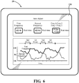
- the user interface 130 may further display a magnitude of the difference between the first and second frequencies calculated by dividing the first frequency by the second frequency. For example, as shown in FIG. 6 , the first frequency is 1.25X greater than the second frequency.
- the user interface 130 may display graphical information, such as a chart, illustrating real-time autonomous adjustment of the first and second frequencies.
- the user interface 130 may provide any other suitable information for assisting the medical personnel. For instance, the user interface 130 may juxtapose the real-time difference between the first and second frequencies with the estimated or real-time positional accuracy and positional speed of the tool 22.
- Autonomous adjustment may occur in response to any suitable event.
- the transformation update frequency is autonomously changed based on feedback.
- autonomous adjustment may occur when the system is engaged in an autonomous or semi-autonomous mode of operation, as described above. Additionally, autonomous adjustment may occur in response to a determined stability or instability of the system. In yet another example, autonomous adjustment occurs in response to determining the target area of interest.
- the first and second frequencies may be autonomously adjusted based on a size of the target area being treated. For instance, if the target area is sized such that the tool 22 cannot move greater than 10 mm in any direction, then the transformation update frequency may be autonomously lowered since the encoder-based data can be very precise when the tool 22 is operated in small areas. On the other hand, if the target area is sized such that the tool 22 can move greater than 100 mm in any direction, the transformation update frequency may autonomously set higher.
- autonomous adjustment of the first and second frequencies may occur in response to switching between the first and second position control modes.
- Changes to the first or second frequency may be associated, for instance, when the robotic manipulator 56 is transitioning from a gross or bulk cutting operation, which requires less positional accuracy to a final or fine cutting operation, which requires greater positional accuracy. This could occur when a bulk cutting bur of tool 22 is replaced with a fine cutting bur.
- the burs may be automatically recognized by the manipulator controller 54 when inserted and thus switch the position control module between position control modes.
- the selection of the first or second position control modes may occur autonomously. Autonomous selection of the first or second position control modes may occur in response to any suitable event, including, but not limited to, those events described above in relation to autonomous adjustment of the first and second frequencies. Other situations may require automatically switching between position control modes for different reasons. Additionally, the user interface 130 may display any suitable information pertaining to autonomous selection of the first or second position control modes.
- adjusting at least one of the first and second frequencies occurs manually.
- the user interface 130 enables the medical personnel to selectively adjust at least one of the first and second frequencies.
- the user interface 130 may allow the medical personnel to selectively increase or decrease the first or second frequency for any given position control mode.
- the user interface 130 may also allow selective adjustment of the difference between the first and second frequency.
- the user interface 130 may allow such manual adjustment for any given position control mode.
- manual adjustment of the first and second frequencies may occur in response to user inputted parameters.
- the system may include a position control module 109 that is a software module operated by the navigation computer 26 to change the first or second frequency based on desired parameters input into the guidance station 20.
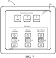
- the first and second frequencies and/or the difference between the first and second frequencies can be set and stored in memory for each given position control mode. For example, in FIG. 7 , a sample first position control mode (bulk) is selected with the first frequency set at 1 KHz and the second frequency set at 100 Hz. The set parameters may be stored in memory and loaded when this position control mode is selected at a later time.
- a sample first position control mode bulk
- the set parameters may be stored in memory and loaded when this position control mode is selected at a later time.
- selection of the first and second position control modes may occur manually.
- the user interface 130 enables the medical personnel to manually select the first and second position control modes, or among a plurality of other position control modes or blend of modes.
- Manual selection of the first or second position control modes may occur in response to any suitable event, including, but not limited to, those events described above in relation to autonomous selection of the first and second position control modes.
- the user interface 130 allows customized control over the positional accuracy and speed of the tool 22.
- adjusting the first and second frequencies occurs manually while selection of the first and second position control modes occurs autonomously.
- adjusting the first and second frequencies may occur autonomously while selection of the first and second position control modes occurs manually.
Description
- The present invention relates generally to a system and method for interacting with an object, and more specifically, a system for controlling a tool that interacts with the object.
- There is an emerging field for using systems, such as robotic systems, to assist medical personnel during a surgical procedure. These systems are configured so that a tool is maneuvered relative to an object of interest at a surgical site. The system typically includes a base with a plurality of linkages extending from the base. The system further includes a tool coupled to the plurality of linkages. The medical personnel may perform the surgical procedure with the system by providing instruction to the system to move the plurality of linkages and the tool with respect to the object.
- Often a navigation system is employed to assist in accurately moving the tool to desired positions relative to the object. Navigation systems provide accurate position and orientation information for the tool and other objects being tracked, especially when these objects move within a relatively large working volume. The navigation-based position and orientation information is often provided to at least partially influence movement and positioning of the linkages of the system relative to a patient's anatomy of interest.
- Additionally, movement of the tool can be controlled in an open loop fashion using position and orientation information derived from a plurality of encoders associated with the plurality of linkages. When utilized for relatively small movements, such encoders can provide more precision than the navigation system in a localized area of interest. As such, encoder-based position and orientation information may be useful when there is a desire to operate at a faster rate outside of the closed loop control of the navigation system. Thus, there are different benefits to using the navigation system and/or the encoders for generating movement commands.
- Conventional systems face challenges with managing the navigation-based and encoder-based information. Mainly, the linkages exhibit a response frequency that is slower than the frequency at which the navigation-based position and orientation information is provided. More specifically, the linkages, motors, joints, etc. of most systems have some flexibility or play. This flexibility limits the reaction time between movement commands and ultimate movement and settling of the tool. If the position and orientation information from the navigation system is utilized for generating movement commands at a frequency faster than the tool is able to move and settle in reaction to such movement commands, the closed loop control of the system will become unstable. Additionally, the slow response frequency of the linkages inhibits the frequency at which this navigation-based position and orientation information can be utilized to influence positioning of the tool. Moreover, conventional systems do not allow for dynamic adjustment of the aforementioned frequencies. Thus, the versatility and stability of conventional systems is limited for various applications and situations.
- Accordingly, there is a need in the art for systems and methods for solving the aforementioned problems.
- Document
US 2008/010706 A1 describes a method for controlling a surgical device. The method includes manipulating the surgical device to perform a procedure on a patient; determining whether a relationship between an anatomy of the patient and a position, an orientation, a velocity, and/or an acceleration of a surgical tool of the surgical device corresponds to a desired relationship between the anatomy and the position, the orientation, the velocity, and/or the acceleration of the surgical tool; and imposing a constraint on the surgical device if the relationship does not correspond to the desired relationship and/or a detection device is unable to detect a position of the anatomy and/or the position of the surgical tool. - Document
WO 2013/052187 A2 relates to computer aided surgery (CAS) utilizing an on tool tracking (OTT) system, including the methods used during computer aided surgery and the devices used during such procedures. Also the structure of the tools used during a procedure and how the tools can be controlled using the on-board tool tracking device are described as well as methods of providing feedback during a procedure to improve either the efficiency or quality, or both, for a procedure including the rate of and type of data processed depending upon a CAS mode. - The invention is defined in appended
independent claim 1, preferred embodiments are described in the dependent claims. - A system is provided for interacting with an object. The system comprises a robotic manipulator having a base and a plurality of linkages. A tool is coupled to the robotic manipulator and movable relative to the base to interact with the object. A plurality of position sensors are associated with the plurality of linkages for providing primary position information at a first frequency. A localizer provides secondary position information at a second frequency. A position controller is configured to position the tool with respect to the object in a first position control mode and a second position control mode based on the primary position information and the secondary position information. A frequency controller is configured to adjust at least one of the first and second frequencies in each of the first and second position control modes. A difference between the first and second frequencies in the first position control mode is different than a difference between the first and second frequencies in the second position control mode.
- A method for positioning a tool in a robotic system is provided. The method includes determining primary position information for the tool at a first frequency. Secondary position information for the tool is determined at a second frequency. A first position control mode and a second position control mode are provided for moving the tool based on the primary position information and the secondary position information. At least one of the first and second frequencies in each of the first and second position control modes is adjusted. A difference between the first and second frequencies in the first position control mode is different than a difference between the first and second frequencies in the second position control mode.
- The system and method effectively provide for customized control of the tool. The difference between the first and second frequencies affects the positional accuracy and positional speed of the tool. Thus, adjusting the difference between the first and second frequencies allows control over the positional speed and the positional accuracy of the tool.
- Additionally, the difference between the first and second frequencies is different between the first and second position control modes. As such, the first and second position control modes have different parameters for the positional accuracy and positional speed of the tool. The system and method can operate according to the first or second position control modes depending on the desired positional accuracy and speed appropriate for the application and situation.
- The system and method additionally provide stability because the first and second frequencies can be dynamically adjusted. If the difference between the first and second frequencies is causing instability, the difference can be dynamically adjusted.
- A positional speed of the tool can be influenced based on the difference between the first and second frequencies such that the positional speed in the first position control mode is greater than the positional speed in the second control mode and/or a positional accuracy of the tool can be influenced based on the difference between the first and second frequencies such that the positional accuracy in the second position control mode is greater than the positional accuracy in the first position control mode.
- Advantages of the present invention will be readily appreciated as the same becomes better understood by reference to the following detailed description when considered in connection with the accompanying drawings wherein:
-
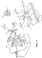
Figure 1 is a perspective view of a guidance station being used in conjunction with a robotic manipulator. -
Figure 2 is a schematic view of the guidance station, tracking devices, pointer, and robotic manipulator. -
Figure 3 is a schematic view of encoders and joint motor controllers of the robotic manipulator. -
Figure 4 is a schematic view of coordinate systems for the localizer and manipulator and other objects. -
Figure 5 is a flow chart of steps taken in one method. -
Figure 6 is a perspective view of an interface according to one embodiment for allowing manual frequency adjustment and manual position control mode selection. -
Figure 7 is a perspective view of an interface according to another embodiment for displaying autonomous frequency adjustment and autonomous position control mode selection. - Systems and methods are disclosed for positioning a
tool 22 of a robotic system. Thetool 22 is coupled to arobotic manipulator 56 and moves relative to a predefined path or anatomical boundary. Thetool 22 is positioned with respect to an object or objects 23. Examples of theobject 23, include, but are not limited to, anatomical features of a patient. InFIG. 1 , the anatomy of the patient shown includes a femur F and a tibia T. Thetool 22 interacts with theobjects 23, and in some instances, manipulates theobjects 23. - Referring to
FIGS. 1 and2 , in one embodiment, the system includes aguidance station 20 coupled to therobotic manipulator 56. InFIG. 1 , theguidance station 20 is shown in an operating room of a medical facility. Theguidance station 20 is set up to track movement of various items in the operating room. Such items may include the anatomy of the patient and thetool 22. Theguidance station 20 tracks these items for purposes of displaying their relative positions and orientations to the medical personnel. In some cases, theguidance station 20 tracks these items for purposes of controlling or constraining movement of thetool 22 relative to a predefined path or anatomical boundary. - The
guidance station 20 includes acomputer cart assembly 24 that houses anavigation computer 26, or other type of control unit. A navigation interface is in operative communication with thenavigation computer 26. In one embodiment, the navigation interface includes afirst display 28 adapted to be situated outside of the sterile field and asecond display 29 adapted to be situated inside the sterile field. Thedisplays computer cart assembly 24. First andsecond input devices navigation computer 26 or otherwise select/control certain aspects of thenavigation computer 26. Other input devices are contemplated including a touch screen (not shown) or voice-activation. - A
localizer 34 communicates with thenavigation computer 26. In the embodiment shown, thelocalizer 34 is an optical localizer and includes a camera unit 36 (also referred to as a sensing device). Thecamera unit 36 has anouter casing 38 that houses one or moreoptical position sensors 40. In some embodiments, at least twooptical sensors 40 are employed, preferably three or more. Theoptical sensors 40 may be three separate charge-coupled devices (CCD). In one embodiment, three one-dimensional CCDs are employed. In other embodiments, separate camera units, each with a separate CCD, or two or more CCDs, may also be arranged around the operating room. The CCDs detect infrared (IR) signals. Thelocalizer 34 may have any suitable configuration for communicating with thenavigation computer 26. -
Camera unit 36 is mounted on an adjustable arm to position theoptical sensors 40 with a field of view of the below discussed trackers that, ideally, is free from obstructions. The adjustable arm allows adjustment of thecamera unit 36 in at least one degree of freedom and, in some embodiments, in two or more degrees of freedom. - The
camera unit 36 includes acamera controller 42 in communication with theoptical sensors 40 to receive signals from theoptical sensors 40. Thecamera controller 42 communicates with thenavigation computer 26 through either a wired or wireless connection (not shown). Position and orientation signals and/or data are transmitted from thecamera unit 36 to thenavigation computer 26 for purposes of tracking the items. - The
displays camera unit 36 may be like those described inU.S. Patent No. 7,725,162 to Malackowski, et al., issued on May 25, 2010 , entitled "Surgery System." - The
navigation computer 26 can be a personal computer or laptop computer.Navigation computer 26 has thedisplays navigation computer 26 is loaded with software as described below. The software converts the signals/data received from thecamera unit 36 into data representative of the position and orientation of the items being tracked. -
Guidance station 20 communicates with a plurality of trackingdevices tracker 44 is firmly affixed to the femur F of the patient and anothertracker 46 is firmly affixed to the tibia T of the patient.Trackers trackers U.S. Patent No. 7,725,162 .Trackers U.S. Provisional Patent Application No. 61/753,219, filed on January 16, 2013 trackers - A
tool tracker 48 is rigidly attached to thetool 22. Thetool tracker 48 may be integrated into thetool 22 during manufacture or may be separately mounted to thetool 22 in preparation for the surgical procedure. The working end of thetool 22, which is being tracked by virtue of thetool tracker 48, may be a rotating bur, electrical ablation device, or the like. The working end of thetool 22 may be presented by a separate energy applicator such as the rotating bur, electrical ablation device, etc. that forms part of thetool 22. - The
trackers navigation computer 26, which, like thecamera unit 36, receives external power. - In the embodiment shown, the
tool 22 forms part of an end effector on therobotic manipulator 56. Therobotic manipulator 56 has abase 57, a plurality of linkages extending from thebase 57, and a plurality of active joints for moving thetool 22 with respect to thebase 57. Therobotic manipulator 56 has the ability to operate in a manual mode, an autonomous mode, or a semi-autonomous mode. Such an arrangement is shown inU.S. Non-provisional Patent Application No. 13/958,070 , entitled, "Surgical Manipulator Capable of Controlling a Surgical Instrument in Multiple Modes," published asUS2014/0039681 . A separate tracker (not shown) may be attached to thebase 57 of therobotic manipulator 56 to track movement of thebase 57. - The
optical sensors 40 of thelocalizer 34 receive light signals from thetrackers trackers tracker optical sensors 40. The active markers can be, for example, light emitting diodes orLEDs 50 transmitting light, such as infrared light. Theoptical sensors 40 preferably have sampling rates of at least 100 Hz, more preferably at least 300 Hz, and most preferably at least 500 Hz or more. In some embodiments, theoptical sensors 40 have sampling rates of 8000 Hz. The sampling rate is the rate at which theoptical sensors 40 receive light signals from sequentially firedLEDs 50. In some embodiments, the light signals from theLEDs 50 are fired at different rates for eachtracker - Referring to
FIG. 2 , each of theLEDs 50 are connected to atracker controller 62 located in a housing (not shown) of the associatedtracker navigation computer 26. In one embodiment, thetracker controllers 62 transmit data on the order of several Megabytes/second through wired connections with thenavigation computer 26. In other embodiments, a wireless connection may be used. In these wireless embodiments, thenavigation computer 26 has a transceiver (not shown) to receive the data from thetracker controller 62. - In other embodiments, the
trackers camera unit 36. The reflected light is then received by theoptical sensors 40. Active and passive tracking elements are well known in the art. - The
navigation computer 26 includes anavigation processor 52. Thecamera unit 36 receives optical signals from theLEDs 50 of thetrackers processor 52 signals relating to the position of theLEDs 50 of thetrackers localizer 34. Based on the received optical signals,navigation processor 52 generates data indicating the relative positions and orientations of thetrackers localizer 34. In some embodiments, thetrackers gyroscope sensor 60 andaccelerometer 70, such as the trackers shown in unpublishedU.S. Provisional Patent Application No. 61/753,219, filed on January 16, 2013 - It should be understood that the
navigation processor 52 may include one or more processors to control operation of thenavigation computer 26. The processors may be any type of microprocessor or multi-processor system. The term processor is not intended to limit any scope to a single processor. - Based on the positions of the
LEDs 50 and previously loaded data relating to the patient's anatomy and geometric information associated with thetool 22,navigation processor 52 determines the position and orientation of thetool 22 relative to the tissue (e.g., femur F and tibia T) against which the working end is to be applied. The previously loaded data includes data associated with pre-operative images, including for example, MRI images and CT scans, taken before the surgical procedure. The previously loaded data also includes geometric relationships between the working end of thetool 22 and theLEDs 50 ontool tracker 48. - Using well known navigation techniques for registration and coordinate system transformation, the patient's anatomy and the working end of the
tool 22 can be registered into a coordinate reference frame of thelocalizer 34 so that the working end and the anatomy can be tracked together using theLEDs 50. A transformation matrix is provided to transform the coordinates of thetool 22 and the patient's anatomy from the localizer coordinate system LCLZ into a manipulator coordinate system MNPL as described below. - A
manipulator controller 54 can use the position and orientation data of thetool 22 and the patient's anatomy to control therobotic manipulator 56 as described in unpublishedU.S. Provisional Patent Application No. 61/679,258 navigation computer 26 to themanipulator controller 54 across wired or wireless connections. - The
navigation processor 52 ormanipulator controller 54 also generates image signals that indicate the relative position of the tool working end to the surgical site. These image signals are applied to thedisplays Displays - Referring to
FIG. 2 , alocalization engine 100 is a software module that can be considered part of the guidance station 20 (ormanipulator controller 54 in some embodiments).Localization engine 100 receives signals from thecamera controller 42 and, in some embodiments, non-optically based signals from thetracker controller 62. Based on these signals,localization engine 100 determines the pose of thetrackers localization engine 100 forwards the signals representative of the poses oftrackers transformer 102. Coordinatetransformer 102 is another software module that forms part of the guidance station 20 (ormanipulator controller 54 in some embodiments). Coordinatetransformer 102 references the data that defines the relationship between the pre-operative images of the patient and thepatient trackers transformer 102 also stores the data indicating the pose of the working end of thetool 22 relative to thetool tracker 48. The various coordinate systems of thetool 22, thetrackers object 23 are shown inFIG. 4 . - The coordinate
transformer 102 then generates data indicating the position and orientation of the working end of thetool 22 relative to the tissue (e.g., bone) against which the working end is applied. The coordinatetransformer 102 also operates to transform the data indicating the pose of the working end of thetool 22 relative to the tissue into the manipulator coordinate system MNPL described further below. Image signals representative of these data are forwarded todisplays trackers sensors 40 is to be maintained. If there are obstructions to the line-of-sight, then errors may occur. - Referring to
FIG. 3 , a plurality of position sensors are associated with the plurality of linkages of therobotic manipulator 56. In one embodiment, the position sensors areencoders encoders FIG. 3 , eachencoder encoder robotic manipulator 56 with which the encoder is associated.Robotic manipulator 56 includes two additional encoders,encoder Encoders robotic manipulator 56 includes two arm structures with six encoders at six active joints. -
Manipulator controller 54 determines the desired location to which thetool 22 should be moved, as described in unpublishedU.S. Provisional Patent Application No. 61/679,258 tool 22, themanipulator controller 54 determines the extent to which each linkage needs to be moved in order to reposition thetool 22 from the current location to the desired location. The data regarding where the linkages are to be positioned is forwarded to joint motor controllers JMC that control active joints of therobotic manipulator 56 to move the linkages and thereby move thetool 22 from the current location to the desired location. - In order to determine the current location of the
tool 22, data from theencoders encoders tool 22 in the manipulator coordinate system MNPL. The preloaded data are data that define the geometry of the linkages and joints. - In one embodiment, the
manipulator controller 54 and joint motor controllers JMC collectively form a position controller that operates to move thetool 22 to commanded positions and/or orientations. The position controller operates in a position control loop. The position control loop may include multiple position control loops in parallel or series for each active joint. The position control loop processes position and orientation information to indicate and direct the pose of thetool 22. - As is described in detail below, the position sensors provide primary position information. In one example, the primary position information includes a pose of the
tool 22 calculated based on information from theencoders encoders step 204. Additionally or alternatively, the primary position information includes a position and orientation of thetool 22 in the manipulator coordinate system MNPL. Alternatively, the primary position information includes position commands for commanding movement of thetool 22 in the manipulator coordinate system MNPL. - The navigation system provides secondary position information. More specifically, the
localizer 34 provides secondary position information. In one example, the secondary position information includes a navigation-based pose of thetool 22 calculated in the localizer coordinate system LCLZ instep 200. In another example, the secondary position information includes position and orientation data transformed from the localizer coordinate system LCLZ to the manipulator coordinate system MNPL. The secondary position information may be processed by thenavigation computer 26. - Referring to
FIG. 4 , relative positions of the localizer coordinate system LCLZ and the manipulator coordinate system MNPL are established so that a transformation matrix can be generated by thenavigation computer 26. The transformation matrix transforms position and orientation data for items from the localizer coordinate system LCLZ to the manipulator coordinate system MNPL. This step may occur before the surgical procedure begins, and periodically during the surgical procedure as described further below. Additionally, primary position information may be generated after the transformation matrix is initially generated. - Referring to
FIG. 5 , position and orientation of thetool tracker 48 is determined in the localizer coordinate system LCLZ so that the secondary position information can be calculated in the localized coordinate system LCLZ. The navigation-based pose of thetool 22 in the localizer coordinate system LCLZ is set as the pose from which the relative pose of the manipulator coordinate system MNPL can be kinematically determined. - The pose of the manipulator coordinate system MNPL relative to the localizer coordinate system LCLZ is based on data from the
encoders encoders step 202. Thetool 22 is moved by the position controller so that thetool 22, and in turn, the working end of thetool 22, is moved to the next commanded position instep 206. - Periodic adjustments are made using newly acquired navigation-based pose data of the
tool 22 to update the transformation matrix. Updating the transformation matrix resets the manipulator coordinate system MNPL relative to the localizer coordinate system LCLZ. One reason for these periodic adjustments is that the encoder-based data is unable to account for any bending of the linkages of therobotic manipulator 56. Instead, such bending is accounted for by estimating forces on the arms. As a result, the navigation-based data complements the encoder-based data since any errors associated with bending of the linkages is automatically accounted for when measuring pose, for instance, with thelocalizer 34 andtool tracker 48. - The
navigation computer 26 periodically updates the transformation matrix to reset the manipulator coordinate system MNPL. This is done to adjust for position inaccuracy that could result from positioning thetool 22 in an open-loop fashion based solely on encoder-derived pose data. By doing so, the encoder-based position and orientation of thetool 22 is corrected/re-calibrated using the navigation-based position and orientation information provided by the navigation computer 26 (i.e., by closing the control loop). - The primary position information is determined at a first frequency. In one embodiment, the position sensors determine the primary position information at the first frequency. Additionally or alternatively, the position controller may determine the primary position information at the first frequency. More specifically, using the signals from the position sensors, the position controller may generate position commands at the first frequency. As such, the first frequency may be defined as a position command frequency in some instances. In such instances, such as those described herein, the term "position command frequency" may be used instead of "first frequency."
- Additionally, the secondary position information is determined at a second frequency. Specifically, the secondary position information is determined by updating the transformation matrix at the second frequency. Said differently, transformation of the position and orientation data is updated from the localizer coordinate system LCLZ to the manipulator coordinate system MNPL at the second frequency. As such, the second frequency may be defined as a transformation update frequency in some instances. In such instances, such as those described herein, the term "transformation update frequency" may be used instead of "second frequency." The transformation update frequency may be established by the
manipulator controller 54. Additionally or alternatively, the transformation update frequency may be established by thenavigation computer 26 and/orlocalizer 34. - In
step 208, a determination is made whether the transformation matrix is to be updated based on the transformation update frequency. If the transformation matrix is not yet to be updated, as dictated by the transformation update frequency, then the method continues to step 204. If the transformation matrix is to be updated, then the method continues back to step 200. - The position controller is configured to position the
tool 22 with respect to theobject 23 in a first position control mode and a second position control mode. The position controller positions thetool 22 in the first and second position control modes based on the primary position information and the secondary position information. - As shown in
FIGS. 1 and2 , the system includes afrequency controller 120. The frequency controller is configured to adjust at least one of the first and second frequencies. Adjustment of the first and second frequencies is made in the first position control mode and the second position control mode. - In one embodiment, the
frequency controller 120 is coupled to both themanipulator controller 54 and thenavigation computer 26. Thefrequency controller 120 may be disposed in any suitable location. For example, as shown inFIG. 1 , thefrequency controller 120 is disposed in therobotic manipulator 56. Alternatively, thefrequency controller 120 may be disposed in theguidance station 20. Thefrequency controller 120 may be a standalone component or integrated as a sub-component of larger device, such as themanipulator controller 54 or thenavigation computer 26. - The
frequency controller 120 adjusts the first and second frequencies so that a difference between the first and second frequencies in the first position control mode is different than a difference between the first and second frequencies in the second position control mode. In one embodiment, the difference between the first and second frequencies is a mathematical subtraction of the second frequency from the first frequency. For example, if the first frequency is 1 KHz and the second frequency is 900 Hz, the difference is 100 Hz. Alternatively, the difference between the first and second frequencies is a mathematical subtraction of the first frequency from the second frequency. The difference may be an absolute difference whereby the absolute value of difference between the first and second frequency is determined. Those skilled in the art appreciate that the difference between the first and second frequencies may be derived according to various other mathematical operations, including, but not limited to, addition, division, differentiation, integration, and the like. - The difference may be discretely measured for any given moment during operation in any given position control mode. For example, the difference between the first and second frequencies in the first position control mode is measured instantaneously at a given time. The difference in the first position control mode measured instantaneously at the given time may be discretely different than the difference in the second position control mode measured instantaneously at the same given time. Alternatively, the difference may be continuously measured during operation in any given position control mode. In such instances, the difference in the first position control mode may be continuously different than the difference in second position control mode. In one example, the difference is averaged over a period of time. Here, the average difference between the first and second frequencies in the first position control mode is different than the average difference between the first and second frequencies in the second position control mode.
- The difference between the first and second frequencies influences a positional speed of the
tool 22 and a positional precision or accuracy of thetool 22. The positional speed is also known as the feed-rate at which thetool 22 moves. - In one sense, the difference between the first and second frequencies signifies the extent to which the primary and secondary position information is used in moving the
tool 22. As described, when thetool 22 is being positioned in a relatively large area of interest, the positional accuracy of thetool 22 is greater when derived from navigation-based secondary position information rather than when derived from encoder-based primary position information. - As a trade-off to the high degree of positional accuracy, the positional speed of the
tool 22 is slower when derived from the secondary position information as compared with when derived from the primary position information. In other words, the positional speed of thetool 22 is faster when derived from the primary position information as compared with the secondary position information. - Generally, the positional speed increases as the difference between the first and second frequencies increases. Conversely, the positional speed decreases as the difference between the first and second frequencies decreases.
- Additionally, the positional accuracy increases as the difference between the first and second frequencies decreases. For example, in some cases, such as when the
tool 22 is being positioned in a relatively large area of interest, the closer the transformation update frequency is to the position command frequency, the more accurate the positioning of thetool 22. On the other hand, the positional accuracy decreases as the difference between the first and second frequencies increases. - In one embodiment, the difference between the first and second frequencies in the first position control mode is greater than the difference between the first and second frequencies in the second position control mode. In some instances, the difference between the first and second frequencies in both the first position control mode and the second position control mode is non-zero. Here, the non-zero difference between the first and second frequencies in the first position control mode is greater than the non-zero difference between the first and second frequencies in the second position control mode.
- In another embodiment, the difference between the first and second frequencies in the first position control mode is non-zero. The first frequency is greater than the second frequency in the first position control mode. The transformation matrix is periodically updated at a transformation update frequency less than the frequency with which position commands are generated by the position controller. Meanwhile, the difference between the first and second frequencies in the second position control mode is approximately zero. This difference is less than the non-zero difference in the first position control mode. The first frequency is substantially equal to the second frequency in the second position control mode. Said differently, the transformation matrix is periodically updated at a transformation update frequency substantially equal to the frequency with which position commands are generated by the position controller.
- Accordingly, in this embodiment, the positional speed of the
tool 22 in the first position control mode is greater than the positional speed of thetool 22 in the second position control mode. In the second position control mode, the positional accuracy of thetool 22 is greater than the positional accuracy of thetool 22 in the first position control mode. As such, the first position control mode is preferred over the second position control mode if bulk cutting in a larger area of interest is desired. However, the second position control mode is preferred over the first position control mode if precision cutting is desired. - For this embodiment, positioning of the
tool 22 in the first position control mode is primarily controlled in an open-loop fashion by the position controller using the encoder-based pose information in the manipulator coordinate system MNPL. In this first position control mode, position commands are sent to the joint motor controllers JMC at a relatively high command frequency, i.e., a frequency greater than a response frequency associated with the plurality of linkages and thetool 22. The response frequency of the plurality of linkages and thetool 22 is the frequency at which complete movement and settling of thetool 22 occurs in response to a position command. Since the linkages, motors, joints, etc. of therobotic manipulator 56 have some flexibility or play there is a limitation on the reaction time between position commands and complete movement and settling of thetool 22. - As such, in this embodiment, the transformation update frequency in the first position control mode is adjusted to be less than the position command frequency and less than the response frequency of the linkages and the
tool 22. If the transformation update frequency was instead set faster than the response frequency, the system may become unstable. As a result, since position commands are being generated at a higher frequency than the transformation update frequency, there is potentially lower accuracy in positioning thetool 22 at the surgical site. - The difference between the first and second frequencies in the first position control mode may be of varying degree. In some cases, the transformation update frequency in the first position control mode is 1/10 or less than the command frequency with which position commands are sent to the joint motor controllers JMC.
- In the second position control mode, the transformation update frequency may be at approximately the same command frequency with which position commands are sent to the joint motor controllers JMC. As such, in some situations like those in which the
tool 22 is being positioned in a relatively large area of interest, the system can more accurately place thetool 22 at the surgical site than in the first position control mode. When switching to the second position control mode, the system will "slow down." In other words, thenavigation computer 26 and the position control loop will work together to track and position thetool 22, but at a frequency less than the response frequency associated with the plurality of linkages and movement and settling of thetool 22. Again, this is done in order to avoid instability. Thus, in some embodiments, the transformation update frequency may be fixed based on the response frequency of the linkages and the command frequency is adjusted relative to the transformation update frequency to adjust accuracy. - The difference between the first and second frequencies in the second position control mode may be of varying degree. In some embodiments, the transformation update frequency in the second position control mode is greater than 1/10 of the command frequency in which position commands are sent to the joint motor controllers JMC.
- Additionally, the system may include a plurality of position control modes in addition to the first and second position control modes. For example, the system may include blended modes having frequency and/or positional accuracy and speed parameters different than the first and second control modes.
- In one embodiment, as shown in
FIG. 6 , adjusting at least one of the first and second frequencies occurs autonomously. In one instance, the first or second frequency is increased or decreased autonomously. In another instance, the difference between the first and second frequencies is adjusted autonomously. - As shown in
FIG. 6 , the system may include auser interface 130 in communication with thefrequency controller 120. In one embodiment, theuser interface 130 is the navigation interface, including thefirst display 28 and/orsecond display 29. Theuser interface 130 communicates to the medical personnel information pertaining to the autonomous adjustment of the first and second frequencies. In one embodiment, theuser interface 130 displays real-time autonomous adjustment of the first and second frequencies. Theuser interface 130 may display the numerical real-time frequencies as well as the real-time difference between the frequencies. In some instances, theuser interface 130 may further display a magnitude of the difference between the first and second frequencies calculated by dividing the first frequency by the second frequency. For example, as shown inFIG. 6 , the first frequency is 1.25X greater than the second frequency. Additionally, theuser interface 130 may display graphical information, such as a chart, illustrating real-time autonomous adjustment of the first and second frequencies. Theuser interface 130 may provide any other suitable information for assisting the medical personnel. For instance, theuser interface 130 may juxtapose the real-time difference between the first and second frequencies with the estimated or real-time positional accuracy and positional speed of thetool 22. - Autonomous adjustment may occur in response to any suitable event. In one embodiment, the transformation update frequency is autonomously changed based on feedback. For example, autonomous adjustment may occur when the system is engaged in an autonomous or semi-autonomous mode of operation, as described above. Additionally, autonomous adjustment may occur in response to a determined stability or instability of the system. In yet another example, autonomous adjustment occurs in response to determining the target area of interest. The first and second frequencies may be autonomously adjusted based on a size of the target area being treated. For instance, if the target area is sized such that the
tool 22 cannot move greater than 10 mm in any direction, then the transformation update frequency may be autonomously lowered since the encoder-based data can be very precise when thetool 22 is operated in small areas. On the other hand, if the target area is sized such that thetool 22 can move greater than 100 mm in any direction, the transformation update frequency may autonomously set higher. - Furthermore, autonomous adjustment of the first and second frequencies may occur in response to switching between the first and second position control modes. Changes to the first or second frequency may be associated, for instance, when the
robotic manipulator 56 is transitioning from a gross or bulk cutting operation, which requires less positional accuracy to a final or fine cutting operation, which requires greater positional accuracy. This could occur when a bulk cutting bur oftool 22 is replaced with a fine cutting bur. The burs may be automatically recognized by themanipulator controller 54 when inserted and thus switch the position control module between position control modes. - Similarly, the selection of the first or second position control modes may occur autonomously. Autonomous selection of the first or second position control modes may occur in response to any suitable event, including, but not limited to, those events described above in relation to autonomous adjustment of the first and second frequencies. Other situations may require automatically switching between position control modes for different reasons. Additionally, the
user interface 130 may display any suitable information pertaining to autonomous selection of the first or second position control modes. - In another embodiment, as shown in
FIG. 7 , adjusting at least one of the first and second frequencies occurs manually. Theuser interface 130 enables the medical personnel to selectively adjust at least one of the first and second frequencies. For example, theuser interface 130 may allow the medical personnel to selectively increase or decrease the first or second frequency for any given position control mode. Theuser interface 130 may also allow selective adjustment of the difference between the first and second frequency. Theuser interface 130 may allow such manual adjustment for any given position control mode. In one embodiment, manual adjustment of the first and second frequencies may occur in response to user inputted parameters. The system may include aposition control module 109 that is a software module operated by thenavigation computer 26 to change the first or second frequency based on desired parameters input into theguidance station 20. These parameters could include desired accuracy, precision, time of surgery, combinations thereof, and the like. Of course, manual adjustment of the first or second frequencies may occur in response to any other suitable event, including, but not limited to, those events described above in relation to autonomous adjustment of the first and second frequencies. - The first and second frequencies and/or the difference between the first and second frequencies can be set and stored in memory for each given position control mode. For example, in
FIG. 7 , a sample first position control mode (bulk) is selected with the first frequency set at 1 KHz and the second frequency set at 100 Hz. The set parameters may be stored in memory and loaded when this position control mode is selected at a later time. - Additionally, selection of the first and second position control modes may occur manually. The
user interface 130 enables the medical personnel to manually select the first and second position control modes, or among a plurality of other position control modes or blend of modes. Manual selection of the first or second position control modes may occur in response to any suitable event, including, but not limited to, those events described above in relation to autonomous selection of the first and second position control modes. - Through manual adjustment of the first and second frequencies and/or manual selection of the first and second position control modes, the
user interface 130 allows customized control over the positional accuracy and speed of thetool 22. - In some embodiments, adjusting the first and second frequencies occurs manually while selection of the first and second position control modes occurs autonomously. Alternatively, adjusting the first and second frequencies may occur autonomously while selection of the first and second position control modes occurs manually.
- The many features and advantages of the invention are apparent from the detailed specification, and thus, it is intended by the appended claims to cover all such features and advantages of the invention which fall within the scope of the invention as defined by the appended claims.
Claims (11)
- A system for interacting with an object (23), said system comprising:a robotic manipulator (56) having a base (57) and a plurality of linkages;a tool (22) coupled to said robotic manipulator (56) and movable relative to said base (57) to interact with the object (23);a plurality of position sensors associated with said plurality of linkages for providing primary position information at a first frequency; anda localizer (34) for providing secondary position information at a second frequency;characterized in that the system further comprises:a position controller (54) configured to position said tool (22) with respect to the object (23) in a first position control mode and a second position control mode based on said primary position information and said secondary position information; anda frequency controller (120) configured to adjust at least one of said first and second frequencies in each of said first and second position control modes so that a difference between said first and second frequencies in said first position control mode is different than a difference between said first and second frequencies in said second position control mode.
- The system as set forth in claim 1, wherein said primary position information includes encoder-based position commands for commanding movement of said tool (22) in a manipulator coordinate system and/or wherein said secondary position information includes navigation-based position and orientation data transformed from a localizer coordinate system to the said manipulator coordinate system.
- The system as set forth in any preceding claim, wherein said difference between said first and second frequencies in said first position control mode is greater than said difference between said first and second frequencies in said second position control mode.
- The system as set forth in any preceding claim, wherein said difference between said first and second frequencies in said first position control mode is non-zero and/or wherein said first frequency is greater than said second frequency in said first position control mode.
- The system as set forth in any one of claims 1-3, wherein said difference between said first and second frequencies in said second position control mode is zero.
- The system as set forth in any one of claims 1-3 and 5, wherein said first frequency is substantially equal to said second frequency in said second position control mode.
- The system as set forth in any one of claims 1-4, wherein said second frequency is approximately 1/10 or less of said first frequency in said first position control mode and said second frequency is equal to or greater than 1/10 of said first frequency in said second position control mode.
- The system as set forth in any preceding claim, wherein said difference between said first and second frequencies influences a positional speed of said tool (22) and wherein, preferably, said positional speed of said tool (22) in said first position control mode is greater than said positional speed of said tool (22) in said second position control mode.
- The system as set forth in any preceding claim, wherein said difference between said first and second frequencies influences a positional accuracy of said tool (22) and wherein, preferably, said positional accuracy of said tool (22) in said second position control mode is greater than said positional accuracy of said tool (22) in said first position control mode.
- The system as set forth in any preceding claim, further including an interface (29) coupled to said frequency controller (120) for enabling selective adjustment of at least one of said first and second frequencies and/or further including an interface (29) coupled to said frequency controller (120) for enabling selection of said first and second position control modes.
- The system as set forth in any preceding claim, wherein said plurality of position sensors include a plurality of position encoders.
Applications Claiming Priority (2)
| Application Number | Priority Date | Filing Date | Title |
|---|---|---|---|
| US201361886838P | 2013-10-04 | 2013-10-04 | |
| PCT/US2014/059005 WO2015051233A1 (en) | 2013-10-04 | 2014-10-03 | System and method for interacting with an object |
Publications (2)
| Publication Number | Publication Date |
|---|---|
| EP3052042A1 EP3052042A1 (en) | 2016-08-10 |
| EP3052042B1 true EP3052042B1 (en) | 2019-11-27 |
Family
ID=51830621
Family Applications (1)
| Application Number | Title | Priority Date | Filing Date |
|---|---|---|---|
| EP14790423.9A Active EP3052042B1 (en) | 2013-10-04 | 2014-10-03 | System for interacting with an object |
Country Status (8)
| Country | Link |
|---|---|
| US (1) | US9339346B2 (en) |
| EP (1) | EP3052042B1 (en) |
| JP (1) | JP6393319B2 (en) |
| KR (1) | KR102303657B1 (en) |
| CN (1) | CN105592818B (en) |
| AU (1) | AU2014329381B2 (en) |
| CA (1) | CA2924820A1 (en) |
| WO (1) | WO2015051233A1 (en) |
Families Citing this family (11)
| Publication number | Priority date | Publication date | Assignee | Title |
|---|---|---|---|---|
| AU2016264199B2 (en) | 2015-05-19 | 2020-10-29 | Mako Surgical Corp. | System and method for manipulating an anatomy |
| US9687982B1 (en) * | 2015-05-27 | 2017-06-27 | X Development Llc | Adapting programming of a robot and/or control of the robot based on one or more parameters of an end effector of the robot |
| US10583557B2 (en) * | 2017-02-10 | 2020-03-10 | GM Global Technology Operations LLC | Redundant underactuated robot with multi-mode control framework |
| CN107536643A (en) * | 2017-08-18 | 2018-01-05 | 北京航空航天大学 | A kind of augmented reality operation guiding system of Healing in Anterior Cruciate Ligament Reconstruction |
| CN112767560A (en) * | 2020-12-30 | 2021-05-07 | 华南理工大学 | Pose adjusting method for three-dimensional simulation model of robot production system |
| CA3212211A1 (en) | 2021-03-31 | 2022-10-06 | David Paul Noonan | Co-manipulation surgical system for use with surgical instruments for performing laparoscopic surgery |
| US11844583B2 (en) | 2021-03-31 | 2023-12-19 | Moon Surgical Sas | Co-manipulation surgical system having an instrument centering mode for automatic scope movements |
| US11812938B2 (en) | 2021-03-31 | 2023-11-14 | Moon Surgical Sas | Co-manipulation surgical system having a coupling mechanism removeably attachable to surgical instruments |
| US11819302B2 (en) | 2021-03-31 | 2023-11-21 | Moon Surgical Sas | Co-manipulation surgical system having user guided stage control |
| US11832909B2 (en) | 2021-03-31 | 2023-12-05 | Moon Surgical Sas | Co-manipulation surgical system having actuatable setup joints |
| US11839442B1 (en) | 2023-01-09 | 2023-12-12 | Moon Surgical Sas | Co-manipulation surgical system for use with surgical instruments for performing laparoscopic surgery while estimating hold force |
Family Cites Families (8)
| Publication number | Priority date | Publication date | Assignee | Title |
|---|---|---|---|---|
| US20010034530A1 (en) | 2000-01-27 | 2001-10-25 | Malackowski Donald W. | Surgery system |
| US9867669B2 (en) * | 2008-12-31 | 2018-01-16 | Intuitive Surgical Operations, Inc. | Configuration marker design and detection for instrument tracking |
| US9526587B2 (en) * | 2008-12-31 | 2016-12-27 | Intuitive Surgical Operations, Inc. | Fiducial marker design and detection for locating surgical instrument in images |
| US9492237B2 (en) * | 2006-05-19 | 2016-11-15 | Mako Surgical Corp. | Method and apparatus for controlling a haptic device |
| WO2008128178A1 (en) * | 2007-04-13 | 2008-10-23 | Nike, Inc. | Unitary vision testing center |
| US8521331B2 (en) * | 2009-11-13 | 2013-08-27 | Intuitive Surgical Operations, Inc. | Patient-side surgeon interface for a minimally invasive, teleoperated surgical instrument |
| AU2012319093A1 (en) | 2011-06-27 | 2014-01-16 | Board Of Regents Of The University Of Nebraska | On-board tool tracking system and methods of computer assisted surgery |
| WO2013016251A2 (en) | 2011-07-28 | 2013-01-31 | Alouani Ali T | Image guided surgery trackers using multiple asynchronous sensors |
-
2014
- 2014-10-03 CA CA2924820A patent/CA2924820A1/en not_active Abandoned
- 2014-10-03 JP JP2016519742A patent/JP6393319B2/en active Active
- 2014-10-03 US US14/505,801 patent/US9339346B2/en active Active
- 2014-10-03 WO PCT/US2014/059005 patent/WO2015051233A1/en active Application Filing
- 2014-10-03 CN CN201480054447.5A patent/CN105592818B/en active Active
- 2014-10-03 EP EP14790423.9A patent/EP3052042B1/en active Active
- 2014-10-03 AU AU2014329381A patent/AU2014329381B2/en active Active
- 2014-10-03 KR KR1020167008754A patent/KR102303657B1/en active IP Right Grant
Non-Patent Citations (1)
| Title |
|---|
| None * |
Also Published As
| Publication number | Publication date |
|---|---|
| AU2014329381A1 (en) | 2016-04-14 |
| EP3052042A1 (en) | 2016-08-10 |
| US9339346B2 (en) | 2016-05-17 |
| JP6393319B2 (en) | 2018-09-19 |
| US20150100161A1 (en) | 2015-04-09 |
| KR102303657B1 (en) | 2021-09-23 |
| JP2016538893A (en) | 2016-12-15 |
| KR20160067110A (en) | 2016-06-13 |
| WO2015051233A1 (en) | 2015-04-09 |
| AU2014329381B2 (en) | 2019-05-23 |
| CN105592818A (en) | 2016-05-18 |
| CA2924820A1 (en) | 2015-04-09 |
| CN105592818B (en) | 2017-11-03 |
Similar Documents
| Publication | Publication Date | Title |
|---|---|---|
| EP3052042B1 (en) | System for interacting with an object | |
| US11529198B2 (en) | Optical and non-optical sensor tracking of objects for a robotic cutting system | |
| WO2017004056A1 (en) | Robotic systems and methods for controlling a tool removing material from a workpiece |
Legal Events
| Date | Code | Title | Description |
|---|---|---|---|
| PUAI | Public reference made under article 153(3) epc to a published international application that has entered the european phase |
Free format text: ORIGINAL CODE: 0009012 |
|
| 17P | Request for examination filed |
Effective date: 20160323 |
|
| AK | Designated contracting states |
Kind code of ref document: A1 Designated state(s): AL AT BE BG CH CY CZ DE DK EE ES FI FR GB GR HR HU IE IS IT LI LT LU LV MC MK MT NL NO PL PT RO RS SE SI SK SM TR |
|
| AX | Request for extension of the european patent |
Extension state: BA ME |
|
| DAX | Request for extension of the european patent (deleted) | ||
| REG | Reference to a national code |
Ref country code: DE Ref legal event code: R079 Ref document number: 602014057554 Country of ref document: DE Free format text: PREVIOUS MAIN CLASS: A61B0090000000 Ipc: B25J0009160000 |
|
| GRAP | Despatch of communication of intention to grant a patent |
Free format text: ORIGINAL CODE: EPIDOSNIGR1 |
|
| STAA | Information on the status of an ep patent application or granted ep patent |
Free format text: STATUS: GRANT OF PATENT IS INTENDED |
|
| RIC1 | Information provided on ipc code assigned before grant |
Ipc: A61B 90/00 20160101ALN20190717BHEP Ipc: A61B 34/30 20160101ALI20190717BHEP Ipc: G05B 19/00 20060101ALN20190717BHEP Ipc: B25J 9/16 20060101AFI20190717BHEP Ipc: A61B 34/20 20160101ALI20190717BHEP |
|
| INTG | Intention to grant announced |
Effective date: 20190730 |
|
| GRAS | Grant fee paid |
Free format text: ORIGINAL CODE: EPIDOSNIGR3 |
|
| GRAA | (expected) grant |
Free format text: ORIGINAL CODE: 0009210 |
|
| STAA | Information on the status of an ep patent application or granted ep patent |
Free format text: STATUS: THE PATENT HAS BEEN GRANTED |
|
| AK | Designated contracting states |
Kind code of ref document: B1 Designated state(s): AL AT BE BG CH CY CZ DE DK EE ES FI FR GB GR HR HU IE IS IT LI LT LU LV MC MK MT NL NO PL PT RO RS SE SI SK SM TR |
|
| REG | Reference to a national code |
Ref country code: GB Ref legal event code: FG4D |
|
| REG | Reference to a national code |
Ref country code: CH Ref legal event code: EP |
|
| REG | Reference to a national code |
Ref country code: AT Ref legal event code: REF Ref document number: 1206162 Country of ref document: AT Kind code of ref document: T Effective date: 20191215 |
|
| REG | Reference to a national code |
Ref country code: DE Ref legal event code: R096 Ref document number: 602014057554 Country of ref document: DE |
|
| REG | Reference to a national code |
Ref country code: IE Ref legal event code: FG4D |
|
| REG | Reference to a national code |
Ref country code: CH Ref legal event code: NV Representative=s name: VALIPAT S.A. C/O BOVARD SA NEUCHATEL, CH |
|
| REG | Reference to a national code |
Ref country code: NL Ref legal event code: MP Effective date: 20191127 |
|
| REG | Reference to a national code |
Ref country code: LT Ref legal event code: MG4D |
|
| PG25 | Lapsed in a contracting state [announced via postgrant information from national office to epo] |
Ref country code: LT Free format text: LAPSE BECAUSE OF FAILURE TO SUBMIT A TRANSLATION OF THE DESCRIPTION OR TO PAY THE FEE WITHIN THE PRESCRIBED TIME-LIMIT Effective date: 20191127 Ref country code: GR Free format text: LAPSE BECAUSE OF FAILURE TO SUBMIT A TRANSLATION OF THE DESCRIPTION OR TO PAY THE FEE WITHIN THE PRESCRIBED TIME-LIMIT Effective date: 20200228 Ref country code: NO Free format text: LAPSE BECAUSE OF FAILURE TO SUBMIT A TRANSLATION OF THE DESCRIPTION OR TO PAY THE FEE WITHIN THE PRESCRIBED TIME-LIMIT Effective date: 20200227 Ref country code: NL Free format text: LAPSE BECAUSE OF FAILURE TO SUBMIT A TRANSLATION OF THE DESCRIPTION OR TO PAY THE FEE WITHIN THE PRESCRIBED TIME-LIMIT Effective date: 20191127 Ref country code: BG Free format text: LAPSE BECAUSE OF FAILURE TO SUBMIT A TRANSLATION OF THE DESCRIPTION OR TO PAY THE FEE WITHIN THE PRESCRIBED TIME-LIMIT Effective date: 20200227 Ref country code: FI Free format text: LAPSE BECAUSE OF FAILURE TO SUBMIT A TRANSLATION OF THE DESCRIPTION OR TO PAY THE FEE WITHIN THE PRESCRIBED TIME-LIMIT Effective date: 20191127 Ref country code: LV Free format text: LAPSE BECAUSE OF FAILURE TO SUBMIT A TRANSLATION OF THE DESCRIPTION OR TO PAY THE FEE WITHIN THE PRESCRIBED TIME-LIMIT Effective date: 20191127 Ref country code: SE Free format text: LAPSE BECAUSE OF FAILURE TO SUBMIT A TRANSLATION OF THE DESCRIPTION OR TO PAY THE FEE WITHIN THE PRESCRIBED TIME-LIMIT Effective date: 20191127 |
|
| PG25 | Lapsed in a contracting state [announced via postgrant information from national office to epo] |
Ref country code: HR Free format text: LAPSE BECAUSE OF FAILURE TO SUBMIT A TRANSLATION OF THE DESCRIPTION OR TO PAY THE FEE WITHIN THE PRESCRIBED TIME-LIMIT Effective date: 20191127 Ref country code: IS Free format text: LAPSE BECAUSE OF FAILURE TO SUBMIT A TRANSLATION OF THE DESCRIPTION OR TO PAY THE FEE WITHIN THE PRESCRIBED TIME-LIMIT Effective date: 20200327 Ref country code: RS Free format text: LAPSE BECAUSE OF FAILURE TO SUBMIT A TRANSLATION OF THE DESCRIPTION OR TO PAY THE FEE WITHIN THE PRESCRIBED TIME-LIMIT Effective date: 20191127 |
|
| PG25 | Lapsed in a contracting state [announced via postgrant information from national office to epo] |
Ref country code: AL Free format text: LAPSE BECAUSE OF FAILURE TO SUBMIT A TRANSLATION OF THE DESCRIPTION OR TO PAY THE FEE WITHIN THE PRESCRIBED TIME-LIMIT Effective date: 20191127 |
|
| PG25 | Lapsed in a contracting state [announced via postgrant information from national office to epo] |
Ref country code: CZ Free format text: LAPSE BECAUSE OF FAILURE TO SUBMIT A TRANSLATION OF THE DESCRIPTION OR TO PAY THE FEE WITHIN THE PRESCRIBED TIME-LIMIT Effective date: 20191127 Ref country code: ES Free format text: LAPSE BECAUSE OF FAILURE TO SUBMIT A TRANSLATION OF THE DESCRIPTION OR TO PAY THE FEE WITHIN THE PRESCRIBED TIME-LIMIT Effective date: 20191127 Ref country code: EE Free format text: LAPSE BECAUSE OF FAILURE TO SUBMIT A TRANSLATION OF THE DESCRIPTION OR TO PAY THE FEE WITHIN THE PRESCRIBED TIME-LIMIT Effective date: 20191127 Ref country code: PT Free format text: LAPSE BECAUSE OF FAILURE TO SUBMIT A TRANSLATION OF THE DESCRIPTION OR TO PAY THE FEE WITHIN THE PRESCRIBED TIME-LIMIT Effective date: 20200419 Ref country code: DK Free format text: LAPSE BECAUSE OF FAILURE TO SUBMIT A TRANSLATION OF THE DESCRIPTION OR TO PAY THE FEE WITHIN THE PRESCRIBED TIME-LIMIT Effective date: 20191127 Ref country code: RO Free format text: LAPSE BECAUSE OF FAILURE TO SUBMIT A TRANSLATION OF THE DESCRIPTION OR TO PAY THE FEE WITHIN THE PRESCRIBED TIME-LIMIT Effective date: 20191127 |
|
| REG | Reference to a national code |
Ref country code: DE Ref legal event code: R097 Ref document number: 602014057554 Country of ref document: DE |
|
| PG25 | Lapsed in a contracting state [announced via postgrant information from national office to epo] |
Ref country code: SK Free format text: LAPSE BECAUSE OF FAILURE TO SUBMIT A TRANSLATION OF THE DESCRIPTION OR TO PAY THE FEE WITHIN THE PRESCRIBED TIME-LIMIT Effective date: 20191127 Ref country code: SM Free format text: LAPSE BECAUSE OF FAILURE TO SUBMIT A TRANSLATION OF THE DESCRIPTION OR TO PAY THE FEE WITHIN THE PRESCRIBED TIME-LIMIT Effective date: 20191127 |
|
| REG | Reference to a national code |
Ref country code: AT Ref legal event code: MK05 Ref document number: 1206162 Country of ref document: AT Kind code of ref document: T Effective date: 20191127 |
|
| PLBE | No opposition filed within time limit |
Free format text: ORIGINAL CODE: 0009261 |
|
| STAA | Information on the status of an ep patent application or granted ep patent |
Free format text: STATUS: NO OPPOSITION FILED WITHIN TIME LIMIT |
|
| 26N | No opposition filed |
Effective date: 20200828 |
|
| PG25 | Lapsed in a contracting state [announced via postgrant information from national office to epo] |
Ref country code: PL Free format text: LAPSE BECAUSE OF FAILURE TO SUBMIT A TRANSLATION OF THE DESCRIPTION OR TO PAY THE FEE WITHIN THE PRESCRIBED TIME-LIMIT Effective date: 20191127 Ref country code: SI Free format text: LAPSE BECAUSE OF FAILURE TO SUBMIT A TRANSLATION OF THE DESCRIPTION OR TO PAY THE FEE WITHIN THE PRESCRIBED TIME-LIMIT Effective date: 20191127 Ref country code: AT Free format text: LAPSE BECAUSE OF FAILURE TO SUBMIT A TRANSLATION OF THE DESCRIPTION OR TO PAY THE FEE WITHIN THE PRESCRIBED TIME-LIMIT Effective date: 20191127 |
|
| PG25 | Lapsed in a contracting state [announced via postgrant information from national office to epo] |
Ref country code: IT Free format text: LAPSE BECAUSE OF FAILURE TO SUBMIT A TRANSLATION OF THE DESCRIPTION OR TO PAY THE FEE WITHIN THE PRESCRIBED TIME-LIMIT Effective date: 20191127 |
|
| PG25 | Lapsed in a contracting state [announced via postgrant information from national office to epo] |
Ref country code: MC Free format text: LAPSE BECAUSE OF FAILURE TO SUBMIT A TRANSLATION OF THE DESCRIPTION OR TO PAY THE FEE WITHIN THE PRESCRIBED TIME-LIMIT Effective date: 20191127 Ref country code: LU Free format text: LAPSE BECAUSE OF NON-PAYMENT OF DUE FEES Effective date: 20201003 |
|
| REG | Reference to a national code |
Ref country code: BE Ref legal event code: MM Effective date: 20201031 |
|
| PG25 | Lapsed in a contracting state [announced via postgrant information from national office to epo] |
Ref country code: BE Free format text: LAPSE BECAUSE OF NON-PAYMENT OF DUE FEES Effective date: 20201031 |
|
| PG25 | Lapsed in a contracting state [announced via postgrant information from national office to epo] |
Ref country code: IE Free format text: LAPSE BECAUSE OF NON-PAYMENT OF DUE FEES Effective date: 20201003 |
|
| PG25 | Lapsed in a contracting state [announced via postgrant information from national office to epo] |
Ref country code: TR Free format text: LAPSE BECAUSE OF FAILURE TO SUBMIT A TRANSLATION OF THE DESCRIPTION OR TO PAY THE FEE WITHIN THE PRESCRIBED TIME-LIMIT Effective date: 20191127 Ref country code: MT Free format text: LAPSE BECAUSE OF FAILURE TO SUBMIT A TRANSLATION OF THE DESCRIPTION OR TO PAY THE FEE WITHIN THE PRESCRIBED TIME-LIMIT Effective date: 20191127 Ref country code: CY Free format text: LAPSE BECAUSE OF FAILURE TO SUBMIT A TRANSLATION OF THE DESCRIPTION OR TO PAY THE FEE WITHIN THE PRESCRIBED TIME-LIMIT Effective date: 20191127 |
|
| PG25 | Lapsed in a contracting state [announced via postgrant information from national office to epo] |
Ref country code: MK Free format text: LAPSE BECAUSE OF FAILURE TO SUBMIT A TRANSLATION OF THE DESCRIPTION OR TO PAY THE FEE WITHIN THE PRESCRIBED TIME-LIMIT Effective date: 20191127 |
|
| P01 | Opt-out of the competence of the unified patent court (upc) registered |
Effective date: 20230522 |
|
| PGFP | Annual fee paid to national office [announced via postgrant information from national office to epo] |
Ref country code: GB Payment date: 20230831 Year of fee payment: 10 |
|
| PGFP | Annual fee paid to national office [announced via postgrant information from national office to epo] |
Ref country code: FR Payment date: 20230911 Year of fee payment: 10 |
|
| PGFP | Annual fee paid to national office [announced via postgrant information from national office to epo] |
Ref country code: DE Payment date: 20230830 Year of fee payment: 10 Ref country code: CH Payment date: 20231102 Year of fee payment: 10 |