EP3051800A1 - Smart phone and external micro-projector thereof - Google Patents
Smart phone and external micro-projector thereof Download PDFInfo
- Publication number
- EP3051800A1 EP3051800A1 EP14812399.5A EP14812399A EP3051800A1 EP 3051800 A1 EP3051800 A1 EP 3051800A1 EP 14812399 A EP14812399 A EP 14812399A EP 3051800 A1 EP3051800 A1 EP 3051800A1
- Authority
- EP
- European Patent Office
- Prior art keywords
- micro projector
- smartphone
- back cover
- disposed
- projector body
- Prior art date
- Legal status (The legal status is an assumption and is not a legal conclusion. Google has not performed a legal analysis and makes no representation as to the accuracy of the status listed.)
- Ceased
Links
Images

Classifications
-
- H—ELECTRICITY
- H04—ELECTRIC COMMUNICATION TECHNIQUE
- H04N—PICTORIAL COMMUNICATION, e.g. TELEVISION
- H04N9/00—Details of colour television systems
- H04N9/12—Picture reproducers
- H04N9/31—Projection devices for colour picture display, e.g. using electronic spatial light modulators [ESLM]
- H04N9/3141—Constructional details thereof
- H04N9/3173—Constructional details thereof wherein the projection device is specially adapted for enhanced portability
-
- G—PHYSICS
- G03—PHOTOGRAPHY; CINEMATOGRAPHY; ANALOGOUS TECHNIQUES USING WAVES OTHER THAN OPTICAL WAVES; ELECTROGRAPHY; HOLOGRAPHY
- G03B—APPARATUS OR ARRANGEMENTS FOR TAKING PHOTOGRAPHS OR FOR PROJECTING OR VIEWING THEM; APPARATUS OR ARRANGEMENTS EMPLOYING ANALOGOUS TECHNIQUES USING WAVES OTHER THAN OPTICAL WAVES; ACCESSORIES THEREFOR
- G03B21/00—Projectors or projection-type viewers; Accessories therefor
-
- G—PHYSICS
- G03—PHOTOGRAPHY; CINEMATOGRAPHY; ANALOGOUS TECHNIQUES USING WAVES OTHER THAN OPTICAL WAVES; ELECTROGRAPHY; HOLOGRAPHY
- G03B—APPARATUS OR ARRANGEMENTS FOR TAKING PHOTOGRAPHS OR FOR PROJECTING OR VIEWING THEM; APPARATUS OR ARRANGEMENTS EMPLOYING ANALOGOUS TECHNIQUES USING WAVES OTHER THAN OPTICAL WAVES; ACCESSORIES THEREFOR
- G03B21/00—Projectors or projection-type viewers; Accessories therefor
- G03B21/14—Details
- G03B21/145—Housing details, e.g. position adjustments thereof
-
- G—PHYSICS
- G03—PHOTOGRAPHY; CINEMATOGRAPHY; ANALOGOUS TECHNIQUES USING WAVES OTHER THAN OPTICAL WAVES; ELECTROGRAPHY; HOLOGRAPHY
- G03B—APPARATUS OR ARRANGEMENTS FOR TAKING PHOTOGRAPHS OR FOR PROJECTING OR VIEWING THEM; APPARATUS OR ARRANGEMENTS EMPLOYING ANALOGOUS TECHNIQUES USING WAVES OTHER THAN OPTICAL WAVES; ACCESSORIES THEREFOR
- G03B29/00—Combinations of cameras, projectors or photographic printing apparatus with non-photographic non-optical apparatus, e.g. clocks or weapons; Cameras having the shape of other objects
-
- G—PHYSICS
- G06—COMPUTING OR CALCULATING; COUNTING
- G06F—ELECTRIC DIGITAL DATA PROCESSING
- G06F1/00—Details not covered by groups G06F3/00 - G06F13/00 and G06F21/00
- G06F1/16—Constructional details or arrangements
- G06F1/1613—Constructional details or arrangements for portable computers
- G06F1/1633—Constructional details or arrangements of portable computers not specific to the type of enclosures covered by groups G06F1/1615 - G06F1/1626
- G06F1/1637—Details related to the display arrangement, including those related to the mounting of the display in the housing
- G06F1/1639—Details related to the display arrangement, including those related to the mounting of the display in the housing the display being based on projection
-
- H—ELECTRICITY
- H04—ELECTRIC COMMUNICATION TECHNIQUE
- H04M—TELEPHONIC COMMUNICATION
- H04M1/00—Substation equipment, e.g. for use by subscribers
- H04M1/02—Constructional features of telephone sets
- H04M1/0202—Portable telephone sets, e.g. cordless phones, mobile phones or bar type handsets
- H04M1/026—Details of the structure or mounting of specific components
- H04M1/0272—Details of the structure or mounting of specific components for a projector or beamer module assembly
-
- H—ELECTRICITY
- H04—ELECTRIC COMMUNICATION TECHNIQUE
- H04M—TELEPHONIC COMMUNICATION
- H04M1/00—Substation equipment, e.g. for use by subscribers
- H04M1/72—Mobile telephones; Cordless telephones, i.e. devices for establishing wireless links to base stations without route selection
- H04M1/724—User interfaces specially adapted for cordless or mobile telephones
- H04M1/72403—User interfaces specially adapted for cordless or mobile telephones with means for local support of applications that increase the functionality
- H04M1/72409—User interfaces specially adapted for cordless or mobile telephones with means for local support of applications that increase the functionality by interfacing with external accessories
-
- H—ELECTRICITY
- H04—ELECTRIC COMMUNICATION TECHNIQUE
- H04M—TELEPHONIC COMMUNICATION
- H04M1/00—Substation equipment, e.g. for use by subscribers
- H04M1/02—Constructional features of telephone sets
- H04M1/0202—Portable telephone sets, e.g. cordless phones, mobile phones or bar type handsets
- H04M1/0254—Portable telephone sets, e.g. cordless phones, mobile phones or bar type handsets comprising one or a plurality of mechanically detachable modules
-
- H—ELECTRICITY
- H04—ELECTRIC COMMUNICATION TECHNIQUE
- H04M—TELEPHONIC COMMUNICATION
- H04M1/00—Substation equipment, e.g. for use by subscribers
- H04M1/02—Constructional features of telephone sets
- H04M1/0202—Portable telephone sets, e.g. cordless phones, mobile phones or bar type handsets
- H04M1/026—Details of the structure or mounting of specific components
- H04M1/0274—Details of the structure or mounting of specific components for an electrical connector module
-
- H—ELECTRICITY
- H04—ELECTRIC COMMUNICATION TECHNIQUE
- H04M—TELEPHONIC COMMUNICATION
- H04M1/00—Substation equipment, e.g. for use by subscribers
- H04M1/02—Constructional features of telephone sets
- H04M1/04—Supports for telephone transmitters or receivers
Definitions
- the present invention relates to a smartphone and an external micro projector, more particularly, to an external micro projector capable of being connected to a smartphone conveniently and being manipulated by a smartphone conveniently.
- the external micro projector can be connected to a smartphone conveniently and manipulated by the smartphone conveniently.
- the present invention provides a smartphone.
- the smartphone can be connected to an external micro projector conveniently and is manipulated conveniently.
- An external micro projector comprises a micro projector body.
- a magnetic block is disposed in the micro projector body.
- the magnetic block is used for magnetically adhering with a magnetic adhesion device in a smartphone.
- a Pogo Pin connector is disposed on the micro projector body.
- the Pogo Pin connector is used for being electrically connected to the smartphone.
- the micro projector body comprises a case, a back cover, and a bottom cover.
- the bottom cover is assembled on a bottom side of the case.
- the back cover is assembled at a back side of the case.
- a projection lamp front lens of the micro projector body is located at a front side of the case, cavities respectively adapted for accommodating the magnetic block and the Pogo Pin connector are disposed on the back side of the case, holes adapted for being inserted by pins on the Pogo Pin connector are formed in the back cover.
- a rechargeable battery is disposed in the micro projector body.
- An universal serial bus port is disposed on the micro projector body. The micro projector body is connected to the smartphone through a data line such that the rechargeable battery charges the smartphone when the micro projector body is separated from the smartphone.
- the holes in the back cover are arranged in a row and located in middle of the back cover, a number of the magnetic blocks is two, the magnetic blocks are respectively disposed on two sides of the Pogo Pin connector, magnetic adhesion surfaces of the magnetic blocks stick to an inner side surface of the back cover after being assembled.
- a support surface is disposed on the back cover, the support surface contacts an edge surface of a back cover of the smartphone, the support surface is used to allow an acute angle more than 45 degrees to be formed between a screen of the smartphone and a bottom of the micro projector body when the back cover contacts with and is fixed to the smartphone.
- the support surface is a flat surface adapted for fitting the edge surface of the back cover of the smartphone.
- the support surface is a concave surface adapted for fitting the edge surface of the back cover of the smartphone.
- a rubber pad is disposed on a bottom surface of the bottom cover.
- the universal serial bus port is connected to a connecting line of a charger to provide electrical power to the micro projector body and the smartphone when the micro projector body is electrically connected to the smartphone through the Pogo Pin connector.
- An external micro projector comprises a micro projector body.
- a magnetic block is disposed in the micro projector body.
- the magnetic block is used for magnetically adhering with a magnetic adhesion device in a smartphone.
- a Pogo Pin connector is disposed on the micro projector body. The Pogo Pin connector is used for being electrically connected to the smartphone.
- the micro projector body comprises a case, a back cover, and a bottom cover
- the bottom cover is assembled on a bottom side of the case
- the back cover is assembled at a back side of the case
- a projection lamp front lens of the micro projector body is located at a front side of the case
- cavities respectively adapted for accommodating the magnetic block and the Pogo Pin connector are disposed on the back side of the case
- holes adapted for being inserted by pins on the Pogo Pin connector are formed in the back cover.
- the holes in the back cover are arranged in a row and located in middle of the back cover, a number of the magnetic blocks is two, the magnetic blocks are respectively disposed on two sides of the Pogo Pin connector, magnetic adhesion surfaces of the magnetic blocks stick to an inner side surface of the back cover after being assembled.
- a support surface is disposed on the back cover, the support surface contacts an edge surface of a back cover of the smartphone, the support surface is used to allow an acute angle more than 45 degrees to be formed between a screen of the smartphone and a bottom of the micro projector body when the back cover contacts with and is fixed to the smartphone.
- the support surface is a flat surface adapted for fitting the edge surface of the back cover of the smartphone.
- the support surface is a concave surface adapted for fitting the edge surface of the back cover of the smartphone.
- a rubber pad is disposed on a bottom surface of the bottom cover.
- a rechargeable battery is disposed in the micro projector body, an universal serial bus port is disposed on the micro projector body, the micro projector body is connected to the smartphone through a data line such that the rechargeable battery charges the smartphone when the micro projector body is separated from the smartphone.
- the universal serial bus port is connected to a connecting line of a charger to provide electrical power to the micro projector body and the smartphone when the micro projector body is electrically connected to the smartphone through the Pogo Pin connector.
- an angle between the screen of the smartphone and the bottom of the micro projector body is 75 degrees.
- a smartphone comprising a smartphone body and an external micro projector, wherein a Pogo Pin socket is disposed on a back cover of the smartphone body, a magnetic adhesion device is disposed in an inner side of the back cover, and the external micro projector comprises a micro projector body, and wherein a magnetic block is disposed in the micro projector body, the magnetic block is used for magnetically adhering with a magnetic adhesion device in a smartphone, a Pogo Pin connector is disposed on the micro projector body, the Pogo Pin connector is used for being electrically connected to the smartphone.
- the external micro projector can be fixed to the smartphone structurally by the magnet because the magnet and the Pogo Pin connector are adopted. There will not be any impact on the appearance of smartphone.
- the Pogo Pin connector can be used to achieve the electrical connection between the smartphone and the external micro projector conveniently without any plugging action.
- the present invention has the advantages of convenient connection and convenient operation.
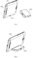
- Fig. 1 is an exploded view of a smartphone and an external micro projector thereof according to the present invention.
- a micro projector body 200 is external to a smartphone 100. That is, the micro projector body serves as an auxiliary accessory of the smartphone 100.
- the micro projector body 200 is combined with the smartphone 100 to achieve on-site projection function. The benefits of doing so are as follows. First, not only is a thickness of the smartphone 100 decreased, but a weight of the smartphone 100 is also reduced. Second, the micro projector body 200 can further act as a mobile power supply to provide the smartphone 100 with enduring electric power under special circumstances.
- the improvements of the external micro projector of the present invention are not limited in this regard.
- the reason lies in that whether the connection of the smartphone 100 to the micro projector body 200 is convenient when the smartphone 100 is utilized to perform projection function and whether users are allowed to operate the smartphone 100 conveniently during the projection process are both practical issues need to be solved.
- a Pogo Pin socket 114 having pins arranged in a row is disposed at an edge of a back cover 110 on the back of the smartphone 100.
- Pogo pin is a precise connector applied to electronic products, such as a cell phone.
- Pogo pin is extensively applied to semiconductor equipment to achieve the connection function.
- the smartphone 100 can be charged and discharged at any time by utilizing the Pogo Pin connectors on a protective cover of a cell phone screen (not shown in the figure) having a wireless charging function.
- a magnetic adhesion device (not shown in the figure) is further disposed on an inner side of the back cover 110 of the smartphone 100 so as to adhere a landing edge of the protective cover of the cell phone screen to the back cover 110 of the smartphone 100 by employing magnetic adhesion principle.
- the protective cover of the cell phone screen can be conveniently removed when the projection function of the smartphone 100 is required.
- the existing magnetic adhesion device and the Pogo Pin socket 114 on the smartphone 100 can be utilized to fix and connect the micro projector body 200 so as to resolve the problems of inconvenient connection and inconvenient operation.
- Pogo Pin connector is a connector with a spring probe. Since the internal structure of the Pogo Pin connector is well known to those skilled in the art, a description in this regard is not provided.
- Fig. 2 is a state diagram of an external micro projector when the external micro projector is in use according to a first embodiment of the present invention.
- the micro projector body 200 lies flat when it projects.
- a screen of the smartphone 100 faces up traversely with its back leaning on a back side of the micro projector body 200 at an angle. In this manner, users are allowed to perform operations on the screen of the smartphone 100 much more conveniently.
- Fig. 3 is an exploded view of a micro projector body according to the present invention.
- the micro projector body comprises a case 210, a back cover 220, a bottom cover 230, a Pogo Pin connector 240, and magnetic blocks 250.
- the bottom cover 230 is assembled to a bottom side of the case 210.
- the back cover 220 is assembled on a back side of the case 210.
- Projection lamp front lens 260 of the micro projector body 200 is located at a front side of the case 210.
- Cavities 204 and 205 respectively adapted for accommodating the Pogo Pin connector 240 and the magnetic blocks 250 are disposed on the back side of the case 210.
- Holes 224 adapted for being inserted by pins on the Pogo Pin connector 240 are formed in the back cover 220.
- the Pogo Pin connector 240 may be a single row Pogo Pin connector that is the same as the above-mentioned Pogo Pin connector on the protective cover of the cell phone screen.
- the holes 224 in the back cover 220 also arrange in a row and located in middle of the back cover 220.
- a number of the magnetic blocks 250 is two.
- the magnetic blocks 250 are respectively disposed on two sides of the Pogo Pin connector 240. Magnetic adhesion surfaces of the magnetic blocks 250 stick to an inner side surface of the back cover 220 after being assembled to enhance the magnetic adhesion force with a magnetic adhesion device in the smartphone.
- a support surface 221 contacting an edge surface of the back cover 110 of the smartphone 100 is disposed on the back cover 220.
- the support surface 221 is used to allow an acute angle more than 45 degrees to be formed between the screen of the smartphone 100 and a bottom of the micro projector body 200 when the back cover 220 contacts with and is fixed to the smartphone 100, as shown in Fig. 1 .
- it is 75 degrees at which users should operate the screen of the smartphone 100 most comfortably.
- the support surface 221 may be a flat surface or a concave surface adapted for fitting the edge surface of the back cover 110 of the smartphone 100. Since the edge surface of the back cover 110 of the smartphone 100 in Fig. 1 is a concave curved surface, the support surface 221 on the back cover 220 being a convex curved surface is shown in Fig. 3 .
- a rubber layer or a rubber pad may be disposed on a bottom surface of the bottom cover 230 to increase the static friction force of the bottom of the micro projector body 200 so as to improve the support stability of the smartphone 100.
- the micro projector body 200 can further act as a mobile power supply to provide the smartphone 100 with enduring electric power under special circumstances. Under such circumstances, a rechargeable battery (not shown in the figure) is disposed in the micro projector body 200.
- a universal serial bus (USB) port 270 may be disposed on a side surface of the micro projector body 200.
- Fig. 4 is a state diagram of an external micro projector when the external micro projector is in use according to a second embodiment of the present invention.
- a data line 300 may be connected to the smartphone 100 through the USB port 270 such that the rechargeable battery in the micro projector body 200 charges the smartphone 100 or provides enduring electric power to the smartphone 100.
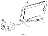
- Fig. 5 is a state diagram of an external micro projector when the external micro projector is in use according to a third embodiment of the present invention.
- the USB port 270 can further be connected to a connecting line 410 of a charger 400 so as to provide electrical power to the micro projector body 200 and the smartphone 100 comprising charging the micro projector body 200 and the smartphone 100 and providing enduring electric power for projection for a long time.
- the present invention further provides a smartphone capable of being connected conveniently and operated conveniently based on the above-mentioned external micro projector.
- the smartphone comprises a smartphone body and an external micro projector.
- a Pogo Pin socket is disposed on a back cover of the smartphone body.
- a magnetic adhesion device is disposed in an inner side of the back cover.
- the magnetic adhesion device and a magnetic block disposed in a micro projector body are magnetically adhered.
- a Pogo Pin connector is disposed on the micro projector body.
- the Pogo Pin connector matches and is combined with the Pogo Pin socket.
- the Pogo Pin connector is used for electrically connecting the smartphone.
- the external micro projector may be the external micro projector of any of the above-mentioned embodiments.
Landscapes
- Engineering & Computer Science (AREA)
- Physics & Mathematics (AREA)
- General Physics & Mathematics (AREA)
- Signal Processing (AREA)
- Theoretical Computer Science (AREA)
- Human Computer Interaction (AREA)
- Computer Hardware Design (AREA)
- Multimedia (AREA)
- General Engineering & Computer Science (AREA)
- Computer Networks & Wireless Communication (AREA)
- Projection Apparatus (AREA)
- Telephone Set Structure (AREA)
- Details Of Connecting Devices For Male And Female Coupling (AREA)
Abstract
Description
- The present invention relates to a smartphone and an external micro projector, more particularly, to an external micro projector capable of being connected to a smartphone conveniently and being manipulated by a smartphone conveniently.
- Nowadays, the projectors on the market are too bulky to carry and are only suitable for use in a fixed place, such as a meeting room or a living room. The now existing projector phones were all in the all-in-one form when they first appeared. After the projection function is added, the phones become thicker which causes an unpleasing appearance and a cumbersome look.
- It is therefore very important to provide a smartphone and an external micro projector thereof so as to resolve the problems of the prior art.
- It is an objective of the present invention to provide an external micro projector to solve the above-mentioned problems. The external micro projector can be connected to a smartphone conveniently and manipulated by the smartphone conveniently.
- The present invention provides a smartphone. The smartphone can be connected to an external micro projector conveniently and is manipulated conveniently.
- An external micro projector comprises a micro projector body. A magnetic block is disposed in the micro projector body. The magnetic block is used for magnetically adhering with a magnetic adhesion device in a smartphone. A Pogo Pin connector is disposed on the micro projector body. The Pogo Pin connector is used for being electrically connected to the smartphone. The micro projector body comprises a case, a back cover, and a bottom cover. The bottom cover is assembled on a bottom side of the case. The back cover is assembled at a back side of the case. A projection lamp front lens of the micro projector body is located at a front side of the case, cavities respectively adapted for accommodating the magnetic block and the Pogo Pin connector are disposed on the back side of the case, holes adapted for being inserted by pins on the Pogo Pin connector are formed in the back cover. A rechargeable battery is disposed in the micro projector body. An universal serial bus port is disposed on the micro projector body. The micro projector body is connected to the smartphone through a data line such that the rechargeable battery charges the smartphone when the micro projector body is separated from the smartphone.
- In one aspect of the present invention, the holes in the back cover are arranged in a row and located in middle of the back cover, a number of the magnetic blocks is two, the magnetic blocks are respectively disposed on two sides of the Pogo Pin connector, magnetic adhesion surfaces of the magnetic blocks stick to an inner side surface of the back cover after being assembled.
- In another aspect of the present invention, a support surface is disposed on the back cover, the support surface contacts an edge surface of a back cover of the smartphone, the support surface is used to allow an acute angle more than 45 degrees to be formed between a screen of the smartphone and a bottom of the micro projector body when the back cover contacts with and is fixed to the smartphone.
- In another aspect of the present invention, the support surface is a flat surface adapted for fitting the edge surface of the back cover of the smartphone.
- In another aspect of the present invention, the support surface is a concave surface adapted for fitting the edge surface of the back cover of the smartphone.
- In another aspect of the present invention, a rubber pad is disposed on a bottom surface of the bottom cover.
- In another aspect of the present invention, the universal serial bus port is connected to a connecting line of a charger to provide electrical power to the micro projector body and the smartphone when the micro projector body is electrically connected to the smartphone through the Pogo Pin connector.
- An external micro projector comprises a micro projector body. A magnetic block is disposed in the micro projector body. The magnetic block is used for magnetically adhering with a magnetic adhesion device in a smartphone. A Pogo Pin connector is disposed on the micro projector body. The Pogo Pin connector is used for being electrically connected to the smartphone.
- In one aspect of the present invention, the micro projector body comprises a case, a back cover, and a bottom cover, the bottom cover is assembled on a bottom side of the case, the back cover is assembled at a back side of the case, a projection lamp front lens of the micro projector body is located at a front side of the case, cavities respectively adapted for accommodating the magnetic block and the Pogo Pin connector are disposed on the back side of the case, holes adapted for being inserted by pins on the Pogo Pin connector are formed in the back cover.
- In another aspect of the present invention, the holes in the back cover are arranged in a row and located in middle of the back cover, a number of the magnetic blocks is two, the magnetic blocks are respectively disposed on two sides of the Pogo Pin connector, magnetic adhesion surfaces of the magnetic blocks stick to an inner side surface of the back cover after being assembled.
- In another aspect of the present invention, a support surface is disposed on the back cover, the support surface contacts an edge surface of a back cover of the smartphone, the support surface is used to allow an acute angle more than 45 degrees to be formed between a screen of the smartphone and a bottom of the micro projector body when the back cover contacts with and is fixed to the smartphone.
- In another aspect of the present invention, the support surface is a flat surface adapted for fitting the edge surface of the back cover of the smartphone.
- In another aspect of the present invention, the support surface is a concave surface adapted for fitting the edge surface of the back cover of the smartphone.
- In another aspect of the present invention, a rubber pad is disposed on a bottom surface of the bottom cover.
- In another aspect of the present invention, a rechargeable battery is disposed in the micro projector body, an universal serial bus port is disposed on the micro projector body, the micro projector body is connected to the smartphone through a data line such that the rechargeable battery charges the smartphone when the micro projector body is separated from the smartphone.
- In another aspect of the present invention, the universal serial bus port is connected to a connecting line of a charger to provide electrical power to the micro projector body and the smartphone when the micro projector body is electrically connected to the smartphone through the Pogo Pin connector.
- In another aspect of the present invention, an angle between the screen of the smartphone and the bottom of the micro projector body is 75 degrees.
- According to the present invention, a smartphone comprising a smartphone body and an external micro projector, wherein a Pogo Pin socket is disposed on a back cover of the smartphone body, a magnetic adhesion device is disposed in an inner side of the back cover, and the external micro projector comprises a micro projector body, and wherein a magnetic block is disposed in the micro projector body, the magnetic block is used for magnetically adhering with a magnetic adhesion device in a smartphone, a Pogo Pin connector is disposed on the micro projector body, the Pogo Pin connector is used for being electrically connected to the smartphone.
- According to the present invention smartphone and external micro projector thereof, the external micro projector can be fixed to the smartphone structurally by the magnet because the magnet and the Pogo Pin connector are adopted. There will not be any impact on the appearance of smartphone. The Pogo Pin connector can be used to achieve the electrical connection between the smartphone and the external micro projector conveniently without any plugging action. The present invention has the advantages of convenient connection and convenient operation.
- The accompanying drawings are included to provide a further understanding of the invention, and are incorporated in and constitute a part of this specification. The drawings illustrate embodiments of the invention and, together with the description, serve to explain the principles of the invention.
-
Fig. 1 is an exploded view of a smartphone and an external micro projector thereof according to the present invention. -
Fig. 2 is a state diagram of an external micro projector when the external micro projector is in use according to a first embodiment of the present invention. -
Fig. 3 is an exploded view of a micro projector body according to the present invention. -
Fig. 4 is a state diagram of an external micro projector when the external micro projector is in use according to a second embodiment of the present invention. -
Fig. 5 is a state diagram of an external micro projector when the external micro projector is in use according to a third embodiment of the present invention. - In order to illustrate the technique and effects of the present invention, a detailed description will be disclosed by the following disclosure in conjunction with figures. It is noted that the same components are labeled by the same number.
- Refer to
Fig. 1, Fig. 1 is an exploded view of a smartphone and an external micro projector thereof according to the present invention. Amicro projector body 200 is external to asmartphone 100. That is, the micro projector body serves as an auxiliary accessory of thesmartphone 100. When a projection function is required at any time and there is no traditional projector on site, themicro projector body 200 is combined with thesmartphone 100 to achieve on-site projection function. The benefits of doing so are as follows. First, not only is a thickness of thesmartphone 100 decreased, but a weight of thesmartphone 100 is also reduced. Second, themicro projector body 200 can further act as a mobile power supply to provide thesmartphone 100 with enduring electric power under special circumstances. - However, the improvements of the external micro projector of the present invention are not limited in this regard. The reason lies in that whether the connection of the
smartphone 100 to themicro projector body 200 is convenient when thesmartphone 100 is utilized to perform projection function and whether users are allowed to operate thesmartphone 100 conveniently during the projection process are both practical issues need to be solved. - In the
smartphone 100 shown inFig. 1 , aPogo Pin socket 114 having pins arranged in a row is disposed at an edge of aback cover 110 on the back of thesmartphone 100. Pogo pin is a precise connector applied to electronic products, such as a cell phone. Pogo pin is extensively applied to semiconductor equipment to achieve the connection function. - The
smartphone 100 can be charged and discharged at any time by utilizing the Pogo Pin connectors on a protective cover of a cell phone screen (not shown in the figure) having a wireless charging function. A magnetic adhesion device (not shown in the figure) is further disposed on an inner side of theback cover 110 of thesmartphone 100 so as to adhere a landing edge of the protective cover of the cell phone screen to theback cover 110 of thesmartphone 100 by employing magnetic adhesion principle. - As such, it is contemplated whether the protective cover of the cell phone screen can be conveniently removed when the projection function of the
smartphone 100 is required. In addition, the existing magnetic adhesion device and thePogo Pin socket 114 on thesmartphone 100 can be utilized to fix and connect themicro projector body 200 so as to resolve the problems of inconvenient connection and inconvenient operation. - The so-called Pogo Pin connector is a connector with a spring probe. Since the internal structure of the Pogo Pin connector is well known to those skilled in the art, a description in this regard is not provided.
-
Fig. 2 is a state diagram of an external micro projector when the external micro projector is in use according to a first embodiment of the present invention. Themicro projector body 200 lies flat when it projects. A screen of thesmartphone 100 faces up traversely with its back leaning on a back side of themicro projector body 200 at an angle. In this manner, users are allowed to perform operations on the screen of thesmartphone 100 much more conveniently. - Refer to
Fig. 3, Fig. 3 is an exploded view of a micro projector body according to the present invention. In a preferred embodiment of the present external micro projector, the micro projector body comprises acase 210, aback cover 220, abottom cover 230, aPogo Pin connector 240, andmagnetic blocks 250. Thebottom cover 230 is assembled to a bottom side of thecase 210. Theback cover 220 is assembled on a back side of thecase 210. Projectionlamp front lens 260 of themicro projector body 200 is located at a front side of thecase 210.Cavities Pogo Pin connector 240 and themagnetic blocks 250 are disposed on the back side of thecase 210.Holes 224 adapted for being inserted by pins on thePogo Pin connector 240 are formed in theback cover 220. - In greater detail, the
Pogo Pin connector 240 may be a single row Pogo Pin connector that is the same as the above-mentioned Pogo Pin connector on the protective cover of the cell phone screen. Theholes 224 in theback cover 220 also arrange in a row and located in middle of theback cover 220. A number of themagnetic blocks 250 is two. Themagnetic blocks 250 are respectively disposed on two sides of thePogo Pin connector 240. Magnetic adhesion surfaces of themagnetic blocks 250 stick to an inner side surface of theback cover 220 after being assembled to enhance the magnetic adhesion force with a magnetic adhesion device in the smartphone. - Preferably, a
support surface 221 contacting an edge surface of theback cover 110 of thesmartphone 100 is disposed on theback cover 220. Thesupport surface 221 is used to allow an acute angle more than 45 degrees to be formed between the screen of thesmartphone 100 and a bottom of themicro projector body 200 when theback cover 220 contacts with and is fixed to thesmartphone 100, as shown inFig. 1 . For example, it is 75 degrees at which users should operate the screen of thesmartphone 100 most comfortably. - Furthermore, the
support surface 221 may be a flat surface or a concave surface adapted for fitting the edge surface of theback cover 110 of thesmartphone 100. Since the edge surface of theback cover 110 of thesmartphone 100 inFig. 1 is a concave curved surface, thesupport surface 221 on theback cover 220 being a convex curved surface is shown inFig. 3 . - Preferably, a rubber layer or a rubber pad (not shown in the figure) may be disposed on a bottom surface of the
bottom cover 230 to increase the static friction force of the bottom of themicro projector body 200 so as to improve the support stability of thesmartphone 100. - Furthermore, as mentioned previously, the
micro projector body 200 can further act as a mobile power supply to provide thesmartphone 100 with enduring electric power under special circumstances. Under such circumstances, a rechargeable battery (not shown in the figure) is disposed in themicro projector body 200. A universal serial bus (USB)port 270 may be disposed on a side surface of themicro projector body 200. - Refer to
Fig. 4, Fig. 4 is a state diagram of an external micro projector when the external micro projector is in use according to a second embodiment of the present invention. When themicro projector body 200 is separated from thesmartphone 100, adata line 300 may be connected to thesmartphone 100 through theUSB port 270 such that the rechargeable battery in themicro projector body 200 charges thesmartphone 100 or provides enduring electric power to thesmartphone 100. - Refer to
Fig. 5, Fig. 5 is a state diagram of an external micro projector when the external micro projector is in use according to a third embodiment of the present invention. Under the circumstances that themicro projector body 200 is electrically connected to thesmartphone 100 through the Pogo Pin connector, theUSB port 270 can further be connected to a connectingline 410 of acharger 400 so as to provide electrical power to themicro projector body 200 and thesmartphone 100 comprising charging themicro projector body 200 and thesmartphone 100 and providing enduring electric power for projection for a long time. - The present invention further provides a smartphone capable of being connected conveniently and operated conveniently based on the above-mentioned external micro projector. The smartphone comprises a smartphone body and an external micro projector. A Pogo Pin socket is disposed on a back cover of the smartphone body. A magnetic adhesion device is disposed in an inner side of the back cover. The magnetic adhesion device and a magnetic block disposed in a micro projector body are magnetically adhered. A Pogo Pin connector is disposed on the micro projector body. The Pogo Pin connector matches and is combined with the Pogo Pin socket. The Pogo Pin connector is used for electrically connecting the smartphone. The external micro projector may be the external micro projector of any of the above-mentioned embodiments.
- The present disclosure is described in detail in accordance with the above contents with the specific preferred examples. However, this present disclosure is not limited to the specific examples. For the ordinary technical personnel of the technical field of the present disclosure, on the premise of keeping the conception of the present disclosure, the technical personnel can also make simple deductions or replacements, and all of which should be considered to belong to the protection scope of the present disclosure.
Claims (20)
- An external micro projector comprising a micro projector body, a magnetic block being disposed in the micro projector body, the magnetic block being used for magnetically adhering with a magnetic adhesion device in a smartphone, a Pogo Pin connector being disposed on the micro projector body, the Pogo Pin connector being used for being electrically connected to the smartphone, wherein the micro projector body comprises a case, a back cover, and a bottom cover, the bottom cover is assembled on a bottom side of the case, the back cover is assembled at a back side of the case, a projection lamp front lens of the micro projector body is located at a front side of the case, cavities respectively adapted for accommodating the magnetic block and the Pogo Pin connector are disposed on the back side of the case, holes adapted for being inserted by pins on the Pogo Pin connector are formed in the back cover, and
wherein a rechargeable battery is disposed in the micro projector body, an universal serial bus port is disposed on the micro projector body, the micro projector body is connected to the smartphone through a data line such that the rechargeable battery charges the smartphone when the micro projector body is separated from the smartphone. - The external micro projector as claimed in claim 1, wherein the holes in the back cover are arranged in a row and located in middle of the back cover, a number of the magnetic blocks is two, the magnetic blocks are respectively disposed on two sides of the Pogo Pin connector, magnetic adhesion surfaces of the magnetic blocks stick to an inner side surface of the back cover after being assembled.
- The external micro projector as claimed in claim 1, wherein a support surface is disposed on the back cover, the support surface contacts an edge surface of a back cover of the smartphone, the support surface is used to allow an acute angle more than 45 degrees to be formed between a screen of the smartphone and a bottom of the micro projector body when the back cover contacts with and is fixed to the back cover of the smartphone.
- The external micro projector as claimed in claim 3, wherein the support surface is a flat surface adapted for fitting the edge surface of the back cover of the smartphone.
- The external micro projector as claimed in claim 3, wherein the support surface is a concave surface adapted for fitting the edge surface of the back cover of the smartphone.
- The external micro projector as claimed in claim 1, wherein a rubber pad is disposed on a bottom surface of the bottom cover.
- The external micro projector as claimed in claim 1, wherein a rubber pad is disposed on a bottom surface of the bottom cover.
- The external micro projector as claimed in claim 1, wherein the universal serial bus port is connected to a connecting line of a charger to provide electrical power to the micro projector body and the smartphone when the micro projector body is electrically connected to the smartphone through the Pogo Pin connector.
- An external micro projector comprising a micro projector body, a magnetic block being disposed in the micro projector body, the magnetic block being used for magnetically adhering with a magnetic adhesion device in a smartphone, a Pogo Pin connector being disposed on the micro projector body, the Pogo Pin connector being used for being electrically connected to the smartphone.
- The external micro projector as claimed in claim 9, wherein the micro projector body comprises a case, a back cover, and a bottom cover, the bottom cover is assembled on a bottom side of the case, the back cover is assembled at a back side of the case, a projection lamp front lens of the micro projector body is located at a front side of the case, cavities respectively adapted for accommodating the magnetic block and the Pogo Pin connector are disposed on the back side of the case, holes adapted for being inserted by pins on the Pogo Pin connector are formed in the back cover.
- The external micro projector as claimed in claim 10, wherein the holes in the back cover are arranged in a row and located in middle of the back cover, a number of the magnetic blocks is two, the magnetic blocks are respectively disposed on two sides of the Pogo Pin connector, magnetic adhesion surfaces of the magnetic blocks stick to an inner side surface of the back cover after being assembled.
- The external micro projector as claimed in claim 10, wherein a support surface is disposed on the back cover, the support surface contacts an edge surface of a back cover of the smartphone, the support surface is used to allow an acute angle more than 45 degrees to be formed between a screen of the smartphone and a bottom of the micro projector body when the back cover contacts with and is fixed to the back cover of the smartphone.
- The external micro projector as claimed in claim 12, wherein the support surface is a flat surface adapted for fitting the edge surface of the back cover of the smartphone.
- The external micro projector as claimed in claim 12, wherein the support surface is a concave surface adapted for fitting the edge surface of the back cover of the smartphone.
- The external micro projector as claimed in claim 10, wherein a rubber pad is disposed on a bottom surface of the bottom cover.
- The external micro projector as claimed in claim 10, wherein a rubber pad is disposed on a bottom surface of the bottom cover.
- The external micro projector as claimed in claim 9, wherein a rechargeable battery is disposed in the micro projector body, an universal serial bus port is disposed on the micro projector body, the micro projector body is connected to the smartphone through a data line such that the rechargeable battery charges the smartphone when the micro projector body is separated from the smartphone.
- The external micro projector as claimed in claim 17, wherein the universal serial bus port is connected to a connecting line of a charger to provide electrical power to the micro projector body and the smartphone when the micro projector body is electrically connected to the smartphone through the Pogo Pin connector.
- The external micro projector as claimed in claim 12, wherein an angle between the screen of the smartphone and the bottom of the micro projector body is 75 degrees.
- A smartphone comprising a smartphone body and an external micro projector, wherein a Pogo Pin socket is disposed on a back cover of the smartphone body, a magnetic adhesion device is disposed in an inner side of the back cover, and the external micro projector comprises a micro projector body, and wherein a magnetic block is disposed in the micro projector body, the magnetic block is used for magnetically adhering with a magnetic adhesion device in a smartphone, a Pogo Pin connector is disposed on the micro projector body, the Pogo Pin connector is used for being electrically connected to the smartphone.
Applications Claiming Priority (2)
| Application Number | Priority Date | Filing Date | Title |
|---|---|---|---|
| CN201310453581.XA CN103475834B (en) | 2013-09-29 | 2013-09-29 | A kind of smart mobile phone and external micro-projector thereof |
| PCT/CN2014/076049 WO2015043171A1 (en) | 2013-09-29 | 2014-04-23 | Smart phone and external micro-projector thereof |
Publications (2)
| Publication Number | Publication Date |
|---|---|
| EP3051800A1 true EP3051800A1 (en) | 2016-08-03 |
| EP3051800A4 EP3051800A4 (en) | 2017-05-10 |
Family
ID=49800515
Family Applications (1)
| Application Number | Title | Priority Date | Filing Date |
|---|---|---|---|
| EP14812399.5A Ceased EP3051800A4 (en) | 2013-09-29 | 2014-04-23 | Smart phone and external micro-projector thereof |
Country Status (4)
| Country | Link |
|---|---|
| US (1) | US9462242B2 (en) |
| EP (1) | EP3051800A4 (en) |
| CN (1) | CN103475834B (en) |
| WO (1) | WO2015043171A1 (en) |
Families Citing this family (15)
| Publication number | Priority date | Publication date | Assignee | Title |
|---|---|---|---|---|
| CN103475834B (en) * | 2013-09-29 | 2016-11-02 | 惠州Tcl移动通信有限公司 | A kind of smart mobile phone and external micro-projector thereof |
| CN103815873B (en) * | 2014-01-02 | 2016-04-06 | 深圳源动创新科技有限公司 | Palm-type multi-parameter measurer and method of work thereof |
| CN103750821B (en) * | 2014-01-02 | 2015-11-25 | 深圳源动创新科技有限公司 | Palm-type multi-parameter measurer and method of work thereof |
| CN106033245A (en) * | 2015-03-17 | 2016-10-19 | 联想(北京)有限公司 | Projection control method and electronic device |
| CN105065962A (en) * | 2015-07-23 | 2015-11-18 | 韦振婕 | Multi-functional table lamp with projector and mobile phone holder |
| CN106028112B (en) * | 2016-05-17 | 2021-02-19 | 联想(北京)有限公司 | Information processing method and electronic equipment |
| CN108021123B (en) * | 2017-12-12 | 2024-01-05 | 中国汽车技术研究中心 | Portable fault detection device of vehicle-mounted data collector |
| CN112422933A (en) * | 2019-08-21 | 2021-02-26 | 台达电子工业股份有限公司 | Projection device, projection system and operation method |
| CN113520004A (en) * | 2020-04-20 | 2021-10-22 | 青岛海信移动通信技术股份有限公司 | A protective cover and terminal equipment |
| CN111552655A (en) * | 2020-04-28 | 2020-08-18 | 上海龙旗科技股份有限公司 | Method and equipment compatible with PogoPin, Y-cable and USB |
| CN112261525A (en) * | 2020-11-17 | 2021-01-22 | 北京声智科技有限公司 | Intelligent sound box |
| CA3227264A1 (en) * | 2021-07-28 | 2023-02-02 | Mark W. Fuller | System for projecting images into a body of water |
| US20230237288A1 (en) * | 2022-01-21 | 2023-07-27 | Marson Technology Co., Ltd. | Rfid reader for smart phone by magnetic connection |
| US20230238738A1 (en) * | 2022-01-21 | 2023-07-27 | Marson Technology Co., Ltd. | Barcode scanner for smart phone by magnetic connection |
| CN116233291A (en) * | 2023-03-15 | 2023-06-06 | 深圳云基智能科技有限公司 | Mobile phone with additional projector and projection method thereof |
Family Cites Families (17)
| Publication number | Priority date | Publication date | Assignee | Title |
|---|---|---|---|---|
| TWM242948U (en) * | 2003-09-12 | 2004-09-01 | Benq Corp | Cellular phone structure and portable electronic apparatus |
| KR100800779B1 (en) * | 2005-06-02 | 2008-02-01 | 삼성전자주식회사 | Connecting device between mobile terminal and external device |
| US20080166006A1 (en) * | 2007-01-06 | 2008-07-10 | Apple Inc | Light diffuser |
| US20090128785A1 (en) * | 2007-11-15 | 2009-05-21 | Silverstein Barry D | Multifunction projector case with screen |
| JP6043482B2 (en) * | 2008-06-03 | 2016-12-14 | トウィードルテック リミテッド ライアビリティ カンパニー | Intelligent board game system, game piece, how to operate intelligent board game system, how to play intelligent board game |
| US8385822B2 (en) * | 2008-09-26 | 2013-02-26 | Hewlett-Packard Development Company, L.P. | Orientation and presence detection for use in configuring operations of computing devices in docked environments |
| US8868939B2 (en) | 2008-09-26 | 2014-10-21 | Qualcomm Incorporated | Portable power supply device with outlet connector |
| KR101555509B1 (en) * | 2009-02-18 | 2015-09-25 | 삼성전자주식회사 | Mobile device having detachable sub module |
| CN102012618B (en) * | 2009-09-08 | 2013-01-30 | 比亚迪股份有限公司 | Portable electronic product with projection device |
| CN201638916U (en) * | 2009-09-24 | 2010-11-17 | 陈桂宏 | Charging rack for mobile phone |
| KR20110060144A (en) * | 2009-11-30 | 2011-06-08 | 삼성전자주식회사 | Collapsible handheld device |
| US8323041B2 (en) * | 2011-02-17 | 2012-12-04 | Citizen Finetech Miyota Co., Ltd. | Connectors for connecting a projector module to an application module |
| CN202309818U (en) * | 2011-10-26 | 2012-07-04 | 福建升龙数码通信技术有限公司 | Mobile phone terminal capable of locating extension module |
| CN102420962A (en) * | 2011-12-09 | 2012-04-18 | 海信集团有限公司 | Projection terminal equipment, light source equipment and projection system |
| CN103166286B (en) | 2013-03-01 | 2015-04-29 | 青岛北斗星应用技术制造有限公司 | Special mobile phone partner of mobile phone with projection function and application thereof |
| CN203193782U (en) * | 2013-03-04 | 2013-09-11 | 王莉 | Micro projector having HDMI and MHL double interfaces and wireless interface |
| CN103475834B (en) | 2013-09-29 | 2016-11-02 | 惠州Tcl移动通信有限公司 | A kind of smart mobile phone and external micro-projector thereof |
-
2013
- 2013-09-29 CN CN201310453581.XA patent/CN103475834B/en active Active
-
2014
- 2014-04-23 WO PCT/CN2014/076049 patent/WO2015043171A1/en not_active Ceased
- 2014-04-23 US US14/417,084 patent/US9462242B2/en active Active
- 2014-04-23 EP EP14812399.5A patent/EP3051800A4/en not_active Ceased
Also Published As
| Publication number | Publication date |
|---|---|
| US20160044291A1 (en) | 2016-02-11 |
| WO2015043171A1 (en) | 2015-04-02 |
| EP3051800A4 (en) | 2017-05-10 |
| CN103475834B (en) | 2016-11-02 |
| CN103475834A (en) | 2013-12-25 |
| US9462242B2 (en) | 2016-10-04 |
Similar Documents
| Publication | Publication Date | Title |
|---|---|---|
| US9462242B2 (en) | Smartphone and external micro projector thereof | |
| US8790120B2 (en) | Electric connector, bracket and electric connector assembly | |
| US20110227527A1 (en) | Wireless charging kit for portable electronic device | |
| CN203481851U (en) | A backup battery product and its stack charging system | |
| CN105991801B (en) | An intelligent terminal accessory system with expandable functions | |
| CN105959437A (en) | Magnetic suction mobile phone shell, magnetic suction mobile phone back clip battery and magnetic suction mobile phone charging device | |
| CN103220890A (en) | Protective shell of electronic device with charge-discharge function | |
| CN205453188U (en) | Charging device of subassembly and electronic product charges | |
| CN210807386U (en) | Wireless earphone accomodates cell-phone shell that charges | |
| CN205377439U (en) | Mobile charging device | |
| CN207559221U (en) | Multifunctional data line | |
| KR101516321B1 (en) | Power supply apparatus for smartphone | |
| CN211266528U (en) | Can dismantle precious cell-phone shell that charges | |
| KR101955772B1 (en) | Auxiliary battery capable of connecting mobile phone by a combination element | |
| CN201623514U (en) | Portable charging and discharging device | |
| CN204578579U (en) | A kind of portable rechargeable cell-phone cover | |
| CN104953630A (en) | Mobile power source | |
| CN107910465A (en) | Back splint battery and protective case component | |
| TWI685166B (en) | Modular hub | |
| CN107017677A (en) | Dorsal clamp type portable power source | |
| CN206893839U (en) | A magnetic interface | |
| CN206697980U (en) | Charger and wrist-watch charging structure | |
| CN205791588U (en) | A kind of quick charged portable power source | |
| CN205545414U (en) | Data interface's that charge electronic equipment protective housing reaches plug connector rather than matcing more | |
| CN205864010U (en) | Mobile electronic device charging device |
Legal Events
| Date | Code | Title | Description |
|---|---|---|---|
| PUAI | Public reference made under article 153(3) epc to a published international application that has entered the european phase |
Free format text: ORIGINAL CODE: 0009012 |
|
| 17P | Request for examination filed |
Effective date: 20160325 |
|
| AK | Designated contracting states |
Kind code of ref document: A1 Designated state(s): AL AT BE BG CH CY CZ DE DK EE ES FI FR GB GR HR HU IE IS IT LI LT LU LV MC MK MT NL NO PL PT RO RS SE SI SK SM TR |
|
| AX | Request for extension of the european patent |
Extension state: BA ME |
|
| DAX | Request for extension of the european patent (deleted) | ||
| A4 | Supplementary search report drawn up and despatched |
Effective date: 20170411 |
|
| RIC1 | Information provided on ipc code assigned before grant |
Ipc: H04N 5/74 20060101AFI20170405BHEP Ipc: G06F 1/16 20060101ALI20170405BHEP |
|
| 17Q | First examination report despatched |
Effective date: 20180405 |
|
| REG | Reference to a national code |
Ref country code: DE Ref legal event code: R003 |
|
| STAA | Information on the status of an ep patent application or granted ep patent |
Free format text: STATUS: THE APPLICATION HAS BEEN REFUSED |
|
| 18R | Application refused |
Effective date: 20190610 |