CN113520004A - Protective sheath and terminal equipment - Google Patents
Protective sheath and terminal equipment Download PDFInfo
- Publication number
- CN113520004A CN113520004A CN202010312339.0A CN202010312339A CN113520004A CN 113520004 A CN113520004 A CN 113520004A CN 202010312339 A CN202010312339 A CN 202010312339A CN 113520004 A CN113520004 A CN 113520004A
- Authority
- CN
- China
- Prior art keywords
- panel
- protective
- electronic product
- protection
- lighting assembly
- Prior art date
- Legal status (The legal status is an assumption and is not a legal conclusion. Google has not performed a legal analysis and makes no representation as to the accuracy of the status listed.)
- Pending
Links
- 230000001681 protective effect Effects 0.000 title claims abstract description 119
- 238000005286 illumination Methods 0.000 description 7
- XEEYBQQBJWHFJM-UHFFFAOYSA-N Iron Chemical group [Fe] XEEYBQQBJWHFJM-UHFFFAOYSA-N 0.000 description 4
- 230000000694 effects Effects 0.000 description 3
- 238000012986 modification Methods 0.000 description 3
- 230000004048 modification Effects 0.000 description 3
- 238000010586 diagram Methods 0.000 description 2
- 229910052742 iron Inorganic materials 0.000 description 2
- 238000004026 adhesive bonding Methods 0.000 description 1
- 239000004020 conductor Substances 0.000 description 1
- 238000010276 construction Methods 0.000 description 1
- 238000005516 engineering process Methods 0.000 description 1
- 230000007613 environmental effect Effects 0.000 description 1
- 238000009434 installation Methods 0.000 description 1
- 210000001503 joint Anatomy 0.000 description 1
- 230000007774 longterm Effects 0.000 description 1
- 238000005457 optimization Methods 0.000 description 1
Images


Classifications
-
- A—HUMAN NECESSITIES
- A45—HAND OR TRAVELLING ARTICLES
- A45C—PURSES; LUGGAGE; HAND CARRIED BAGS
- A45C11/00—Receptacles for purposes not provided for in groups A45C1/00-A45C9/00
-
- A—HUMAN NECESSITIES
- A45—HAND OR TRAVELLING ARTICLES
- A45C—PURSES; LUGGAGE; HAND CARRIED BAGS
- A45C15/00—Purses, bags, luggage or other receptacles covered by groups A45C1/00 - A45C11/00, combined with other objects or articles
- A45C15/06—Purses, bags, luggage or other receptacles covered by groups A45C1/00 - A45C11/00, combined with other objects or articles with illuminating devices
-
- G—PHYSICS
- G06—COMPUTING; CALCULATING OR COUNTING
- G06F—ELECTRIC DIGITAL DATA PROCESSING
- G06F1/00—Details not covered by groups G06F3/00 - G06F13/00 and G06F21/00
- G06F1/16—Constructional details or arrangements
- G06F1/1613—Constructional details or arrangements for portable computers
- G06F1/1626—Constructional details or arrangements for portable computers with a single-body enclosure integrating a flat display, e.g. Personal Digital Assistants [PDAs]
-
- A—HUMAN NECESSITIES
- A45—HAND OR TRAVELLING ARTICLES
- A45C—PURSES; LUGGAGE; HAND CARRIED BAGS
- A45C11/00—Receptacles for purposes not provided for in groups A45C1/00-A45C9/00
- A45C2011/002—Receptacles for purposes not provided for in groups A45C1/00-A45C9/00 for portable handheld communication devices, e.g. mobile phone, pager, beeper, PDA, smart phone
Abstract
The invention relates to the technical field of terminal equipment, in particular to a protective sleeve and terminal equipment. The protective sleeve comprises a protective shell, a mounting shell, a lighting assembly and a connecting assembly; the protective shell comprises a first protective panel and a second protective panel which are connected, and the first protective panel can be folded relative to the second protective panel; the mounting shell is used for accommodating an electronic product and is fixed on the inner side surface of the second protection panel; when the first protection panel is folded towards the inner side surface of the second protection panel relative to the second protection panel, the inner side surface of the first protection panel is opposite to the mounting shell; the lighting assembly is arranged on the inner side surface of the first protection panel to provide light for a screen of an electronic product; the connecting assembly is electrically connected with the lighting assembly and is provided with a wiring port, and the wiring port is used for butting an external interface of an electronic product. If the ambient light is darker, lighting assembly can provide the light for electronic product, makes things convenient for the normal use of this type of electronic product under the low light condition, promotes consumer and uses the experience.
Description
Technical Field
The invention relates to the technical field of terminal equipment, in particular to a protective sleeve and terminal equipment.
Background
With the development of science and technology, portable electronic products such as tablet computers bring more colorful experience to daily life of people. In order to increase the service life of such electronic products, a protective sleeve is generally disposed on the terminal device for protection. Taking a tablet personal computer as an example, the traditional protective sleeve only plays a role in collision avoidance, and further optimization and improvement are not provided for the functional use of the tablet personal computer.
On the other hand, the existing tablet computer depends on the external environment (especially a tablet computer with a partially non-screen self-luminous function), if the external environment light is insufficient, the user cannot see the screen of the tablet computer, and the user cannot feel comfortable when watching the screen of the tablet computer in a weak light or no light environment, and even the user may hurt the eyes after long-term use.
Thus, exploring and attempting to diversify the functionality of protective sleeves may lead to a better use experience for consumers.
Disclosure of Invention
The embodiment of the invention provides a protective sleeve and terminal equipment, wherein a lighting function is integrated in the protective sleeve, and brightness can be provided for electronic products under the condition of weak light.
In a first aspect, an embodiment of the present invention provides a protective sheath, including:
a protective case comprising a first protective panel and a second protective panel having a unitary construction, the first protective panel being foldable relative to the second protective panel;
the mounting shell is used for accommodating an electronic product and is fixed on the inner side surface of the second protection panel; when the first protection panel is folded towards the inner side face of the second protection panel relative to the second protection panel, the inner side face of the first protection panel is opposite to the mounting shell;
the lighting assembly is arranged on the inner side surface of the first protective panel and provides light for a screen of the electronic product;
the connecting assembly is electrically connected with the lighting assembly and is provided with a wiring port, and the wiring port is used for butting the external interface of the electronic product.
Among the above-mentioned technical scheme, protective housing and installation shell cooperation provide the support protection to electronic product, and when the consumer used electronic product, if ambient light was darker, lighting assembly can provide light for electronic product, makes things convenient for the normal use of this type of electronic product under the low light condition, provides more comfortable use for the consumer and experiences.
Optionally, the first protection panel includes a first panel, a second panel and a third panel connected in sequence; the second panel is foldable relative to the first panel, and the third panel is foldable relative to the second panel;
the first panel is connected with the second protection panel, and the lighting assembly is fixed on the inner side face of the first panel.
Optionally, a receiving groove for fixing the lighting assembly is formed on the first panel, and the receiving groove has an opening located on an inner side surface of the first panel for light of the lighting assembly to exit.
Optionally, a first positioning member is disposed on the third panel, and a second positioning member is disposed on the second protective panel;
when the second panel is folded relative to the first panel and the third panel is folded relative to the second panel until the third panel is attached to the outer side face of the second protection panel, the first positioning piece and the second positioning piece are matched to form a plurality of positioning stations;
the first positioning piece and the second positioning piece are matched in a plurality of positioning stations to be switched and used for adjusting the angle of the first panel relative to the second protection panel so as to adjust the light emitting angle of the lighting assembly.
Optionally, the first positioning element is an iron sheet, and the second positioning element is a magnet.
Optionally, the lighting component is a light strip.
Optionally, the end of the light strip is arc-shaped.
Optionally, the connection assembly extends from the first protective panel to the mounting shell;
a first threading groove for the connecting assembly to pass through is formed in the first protection panel, and a second threading groove for the connecting assembly to pass through is formed in the mounting shell.
In a second aspect, an embodiment of the present invention provides a terminal device, where the terminal device includes an electronic product and a protective cover;
the protective sleeve comprises a protective shell, a mounting shell, a lighting assembly and a connecting assembly;
the protective case comprises a first protective panel and a second protective panel, wherein the first protective panel can be folded relative to the second protective panel;
the mounting shell is fixed on the inner side surface of the second protection panel; when the first protection panel is folded towards the inner side face of the second protection panel relative to the second protection panel, the inner side face of the first protection panel is opposite to the screen of the electronic product;
the lighting assembly is arranged on the inner side surface of the first protection panel to provide light for the screen of the electronic product;
the electronic product is accommodated in the mounting shell; the connecting assembly is connected with the lighting assembly and is provided with a wiring port, and the wiring port is connected with an external interface of the electronic product.
Drawings
In order to more clearly illustrate the technical solutions in the embodiments of the present invention, the drawings needed to be used in the description of the embodiments will be briefly introduced below, and it is obvious that the drawings in the following description are only some embodiments of the present invention, and it is obvious for those skilled in the art to obtain other drawings based on these drawings without creative efforts.
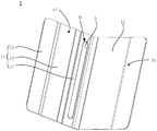
Fig. 1 is a schematic structural view of a protective sheath according to an embodiment of the present invention;
fig. 2 is a schematic view illustrating a state of a protective cover cooperating with an electronic product according to an embodiment of the present invention;
FIG. 3 is a front view of a protective sheath according to an embodiment of the present invention;
FIG. 4 is a schematic cross-sectional view taken along line E-E in FIG. 3;
FIG. 5 is a schematic structural diagram of a protective casing in a protective casing according to an embodiment of the present invention;
FIG. 6 is a schematic view of a protective sheath of the present invention in a folded state;
FIG. 7 is a schematic view of the electronic product in a state where the protective cover shown in FIG. 6 is engaged with the electronic product;
FIG. 8 is a schematic view of the electronic product being disposed in the protective cover shown in FIG. 6 and being engaged with the electronic product at another angle;
fig. 9 is a schematic view illustrating a principle of cooperation between a first positioning element and a second positioning element in a protective sheath according to an embodiment of the present invention;
fig. 10 is a front view of a usage state of a terminal device according to an embodiment of the present invention;
FIG. 11 is a schematic cross-sectional view of F-F in FIG. 10;
fig. 12 is an enlarged schematic view of a portion Q in fig. 11.
Reference numerals: 100-a terminal device; 10-a protective sheath; 20-an electronic product; 1-protective shell; 11-a first protective panel; 111-a first panel; 112-a second panel; 113-a second panel; 12-a second protective panel; 2-mounting the housing; 3-a lighting assembly; 4-a connecting assembly; 51-a first positioning member; 52-second positioning element.
Detailed Description
In order to make the objects, technical solutions and advantages of the present invention clearer, the present invention will be described in further detail with reference to the accompanying drawings, and it is apparent that the described embodiments are only a part of the embodiments of the present invention, not all of the embodiments. All other embodiments, which can be derived by a person skilled in the art from the embodiments given herein without making any creative effort, shall fall within the protection scope of the present invention.
Fig. 1 is a schematic structural diagram of a protective case 10 according to an embodiment of the present invention, where the protective case 10 includes a protective case 1, a mounting case 2, a lighting assembly 3, and a connecting assembly 4; wherein the protective casing 1 comprises a first protective panel 11 and a second protective panel 12, the first protective panel 11 being foldable relative to the second protective panel 12. When the first protective panel 11 is folded toward the inner side b1 of the second protective panel 12 with respect to the second protective panel 12, a receiving space may be formed between the inner side a1 of the first protective panel 11 and the inner side b1 of the second protective panel 12. The mounting case 2 is fixed to the inner side surface b1 of the second protective panel 12 of the protective case 1, and when the first protective panel 11 is folded toward the inner side surface b1 of the second protective panel 12 with respect to the second protective panel 12, the inner side surface a1 of the first protective panel 11 faces the mounting case 2. At the inner side a1 of the first protection panel 11, a lighting assembly 3 is further provided, and a connection assembly 4 is connected with the lighting assembly 3, since the connection assembly 4 is hidden inside the protection case 1 and the mounting case 2, not shown in fig. 1.
As shown in fig. 2, the electronic product 20 such as a tablet computer is disposed in the mounting case 2 of the protective cover 10, the screen of the electronic product 20 faces a surface away from the inner side b1 of the second protective panel 12, the first protective panel 11 forms an included angle with respect to the second protective panel 12, and the light emitted from the lighting assembly 3 disposed on the first protective panel 11 can irradiate the screen surface of the electronic product 20, so as to provide light for the electronic product 20. This usage status may be suitable for the consumer to use the electronic product 20 under low light conditions, which provides a more comfortable usage experience for the consumer.
It should be noted that the screen of the electronic product 20 may be a reflective screen or a transmissive screen, and it is understood that the reflective screen has stronger environmental dependency and normal use of the reflective screen is affected when the ambient light is weaker, so that the protective cover 10 shown in the embodiment of the present application can exert better use effect when applied to the electronic product 20 having the reflective screen.
The included angle between the first protection panel 11 and the second protection panel 12 shown in fig. 2 can completely expose the screen of the electronic product 20, which is convenient for the consumer to use; in order to provide better lighting effect, the lighting assembly 3 is disposed on a side of the first protective panel 11 close to the second protective panel 12, so that the lighting assembly 3 is closer to the screen of the electronic product 20. Moreover, the light emitted by the lighting assembly 3 is scattered light, so that a good light compensation effect can be achieved.
The first protection panel 11 in fig. 1 is folded toward the inner side surface b1 of the second protection panel 12 with respect to the second protection panel 12 until the first protection panel 11 and the second protection panel 12 are parallel to each other (the inner side surface a1 of the first protection panel 11 is opposite to the inner side surface b1 of the second protection panel 12), and a front view of the protection cover 10 shown in fig. 3 is obtained, in which the first protection panel 11 shields the second protection panel 12 and the mounting case 2.
Cutting the protective cover 10 along the plane E-E in fig. 3 to obtain the schematic sectional structure shown in fig. 4, the structure of the connecting assembly 4 can be seen, where the connecting assembly 4 is shown as a flexible conductor extending from the first protective panel 11 to the mounting shell 2, and a first threading slot is formed in the first protective panel 11 for the connecting assembly 4 to pass through, so that the connecting assembly 4 is connected with the lighting assembly 3 in the first protective panel 11; correspondingly, a second threading slot for the connection component 4 to pass through is correspondingly formed in the mounting shell 2, so that the connection component 4 forms a connection port a on the inner side of the mounting shell 2, when the electronic product 20 is placed in the mounting shell 2, the connection port a can be in butt joint with an external interface (which may be specifically a POGOPIN interface or a USB interface of the electronic product 20) of the electronic product 20, thereby realizing circuit connection between the illumination component 3 and the electronic product 20, the electronic product 20 can supply power to the illumination lamp 22, and the on/off and brightness adjustment of the illumination component 3 can be controlled by a control program built in the electronic product 20. Of course, the on/off or brightness adjustment of the lighting assembly 3 can also be controlled independently of the electronic product 20, that is, the electronic product 20 only supplies power to the illumination lamp 22, and the switch and the brightness adjustment button are independently arranged on the lighting assembly 3.
In a possible implementation manner, the structure of the protective casing 1 may be as shown in fig. 5, the first protective panel 11 may include a first panel 111, a second panel 112, and a third panel 113 sequentially connected in a direction perpendicular to a connection line between the first protective panel 11 and the second protective panel 12, wherein the second panel 112 may be folded with respect to the first panel 111, the third panel 113 may be folded with respect to the second panel 112, and an accommodating groove B is disposed on the first panel 111, and is used for accommodating the lighting assembly 3, and the accommodating groove B has an opening located on the first panel 111, so that light of the lighting assembly 3 may be emitted from the opening. The accommodating groove B can be matched with the structure of the lighting assembly 3, so that the lighting assembly 3 can be limited and fixed in the accommodating groove B; the lighting assembly 3 can also be fixed in the accommodating groove B by gluing.
The lighting assembly 3 can specifically adopt a lamp strip which has a light and thin structure and is conveniently placed in the accommodating groove B. For the lamp area structure softer, the structure in lamp area can be rectangular shape and both ends are the arc, correspondingly, holding tank B's structure also can set up to rectangular shape, both ends are the arc, with the structure phase-match in lamp area.
As shown in fig. 6, which is a schematic side view illustrating a folded state of the protective case 1 shown in fig. 3, the first panel 111, the second panel 112 and the third panel 113 form an approximately triangular structure therebetween, which can provide stable support for the lighting assembly 3 disposed on the first panel 111. When the electronic product 20 is placed in the mounting case 2 of the protective cover 10 shown in fig. 6, the using state shown in fig. 7 can be obtained, the folding of the first panel 111, the second panel 112 and the third panel 113 can provide stable support for the lighting assembly 3, and can also prevent the first protective panel 11 from shielding the screen of the electronic product 20, and the protective cover 10 shown in fig. 5 can be placed horizontally to facilitate the viewing of the consumer.
Referring to fig. 8, which shows a schematic structural view of another angle of the structure shown in fig. 7, a first positioning member 51 is disposed on the third panel 113, a second positioning member 52 is disposed on the second protection panel 12, and when the second panel 112 is folded with respect to the first panel 111 and the third panel 113 is folded with respect to the second panel 112 until the third panel 113 is attached to the outer side b2 of the second protection panel 12, the first positioning member 51 and the second positioning member 52 can cooperate to form a plurality of positioning stations; fig. 8 shows a possible way of realising that the first positioning element 51 is a magnet, which exposes the third panel 113; the second positioning element 52 is an iron sheet, which can be hidden in the second protective panel 12 (shown by a dotted line in fig. 8, the second positioning element 52 is a long strip, and the first positioning element 51 reciprocates along the arrow direction shown in fig. 8 to enable the first positioning element 51 and the second positioning element 52 to be matched at multiple positions, of course, each matching position can enable the structure among the first panel 111, the second panel 112, and the third panel 113 to be adjusted.
It should be noted that the first positioning element 51 and the second positioning element 52 may also be implemented in other forms, for example, the first positioning element 51 may be provided with a male buckle, the second positioning element 52 is implemented by a row of female buckles extending in the direction shown in fig. 8, the male buckle may be fixed with each female buckle, so as to implement the positioning of the third panel 113 relative to the second protection panel 12; other implementations are not described in detail herein.
Referring to the first positioning member 51 and the second positioning member 52 of the matching adjustment illustrated in fig. 9, the first positioning member 51 should be hidden in the third panel 113, and the second positioning member 52 should be hidden in the second protective panel 12, but for the purpose of illustrating the working principle, the first positioning member 51 and the second positioning member 52 are shown in shadow. As shown in fig. 9, a solid line indicates an initial position, a matching position of the first positioning element 51 and the second positioning element 52 is m, and an included angle α is formed between the first panel 111 and the second protection panel 12; the third panel 113 is pushed in the direction shown by the arrow in the figure, that is, the matching position of the first positioning element 51 and the second positioning element 52 is moved from m to n, and the triangle formed between the first panel 111, the second panel 112 and the third panel 113 changes, so that the included angle between the first panel 111 and the second protection panel 12 is increased from α to β, the angle of the first panel 111 changes, and correspondingly, the structure of the lighting assembly 3 arranged on the first panel 111 relative to the screen of the electronic product 20 also changes, and the light emitting angle adjustment of the lighting assembly 3 can be realized.
Based on the same technical concept, the embodiment of the present invention further provides a terminal device 100, as shown in fig. 10, where the terminal device 100 includes an electronic product 20 and any one of the protective cases 10 provided in the above technical solutions. The protective sleeve 10 comprises a protective shell 1, a mounting shell 2, a lighting assembly 3 and a connecting assembly 4; the protective case 1 comprises a first protective panel 11 and a second protective panel 12, where the first protective panel 11 is shown in a folded state with a first panel 111, a second panel 112 and a third panel 113 connected in series; the mounting case 2 is fixed to the inner side surface b1 of the second protection panel 12 for fixing the electronic product 20, and the lighting assembly 3 is mounted on the side of the first panel 111 facing the electronic product 20 for providing light to the electronic product 20. It is understood that not all of the structures are shown in fig. 10 due to the viewing angle.
Cutting the terminal device 100 along the plane F-F in fig. 10 to obtain the schematic cross-sectional structure shown in fig. 11, wherein the electronic product 20 is accommodated in the mounting case 2; the first panel 111, the second panel 112 and the third panel 113 of the first protection panel 11 are folded to provide support for the lighting assembly 3, and the third panel 113 is attached to the side of the second protection panel 12 facing away from the electronic product 20.
Referring to the enlarged view of the portion Q in fig. 11 shown in fig. 12, one end of the connection component 4 is connected to the lighting component 3, and the other end thereof forms a connection port a, the connection port a is connected to the external interface C of the electronic product 20, and the electronic product 20 can supply power to the lighting component 3 to meet the illumination requirement of the electronic product 20. In addition, the electronic product 20 may have a program embedded therein, which can control the illumination lamp 22, and is used for controlling the on/off and brightness adjustment of the illumination assembly 3.
It will be apparent to those skilled in the art that various changes and modifications may be made in the embodiments of the present invention without departing from the spirit and scope of the invention. Thus, if such modifications and variations of the present invention fall within the scope of the claims of the present invention and their equivalents, the present invention is also intended to include such modifications and variations.
Claims (9)
1. A protective casing, comprising:
the protective shell comprises a first protective panel and a second protective panel which are connected, and the first protective panel can be folded relative to the second protective panel;
the mounting shell is used for accommodating an electronic product and is fixed on the inner side surface of the second protection panel; when the first protection panel is folded towards the inner side face of the second protection panel relative to the second protection panel, the inner side face of the first protection panel is opposite to the mounting shell;
the lighting assembly is arranged on the inner side surface of the first protective panel and provides light for a screen of the electronic product;
the connecting assembly is electrically connected with the lighting assembly and forms a wiring port, and the wiring port is used for butting the external interface of the electronic product.
2. The protective cover of claim 1, wherein the first protective panel comprises a first panel, a second panel, and a third panel connected in series; the second panel is foldable relative to the first panel, and the third panel is foldable relative to the second panel;
the first panel is connected with the second protection panel, and the lighting assembly is fixed on the first panel.
3. The protective cover of claim 2, wherein the first panel has a receiving groove formed thereon for fixing the lighting assembly, the receiving groove having an opening at an inner side of the first panel for emitting light of the lighting assembly.
4. The protective cover of claim 2, wherein a first positioning member is disposed on the third panel and a second positioning member is disposed on the second protective panel;
when the second panel is folded relative to the first panel and the third panel is folded relative to the second panel until the third panel is attached to the outer side face of the second protection panel, the first positioning piece and the second positioning piece are matched to form a plurality of positioning stations;
the first positioning piece and the second positioning piece are matched in a plurality of positioning stations to be switched and used for adjusting the angle of the first panel relative to the second protection panel so as to adjust the light emitting angle of the lighting assembly.
5. The protective cover of claim 4, wherein said first positioning element is magnetically engaged with said second positioning element.
6. The protective cover of claim 1, wherein the lighting assembly is a light strip.
7. The protective cover of claim 6, wherein the end of the light strip is arcuate.
8. The protective casing of any one of claims 1-7, wherein the connection assembly extends from the first protective panel to the mounting casing;
a first threading groove for the connecting assembly to pass through is formed in the first protection panel, and a second threading groove for the connecting assembly to pass through is formed in the mounting shell.
9. The terminal equipment is characterized by comprising an electronic product and a protective sleeve, wherein the protective sleeve comprises a protective shell, a mounting shell, an illuminating assembly and a connecting assembly;
the protective case comprises a first protective panel and a second protective panel, wherein the first protective panel can be folded relative to the second protective panel;
the mounting shell is fixed on the inner side surface of the second protection panel; when the first protection panel is folded towards the inner side face of the second protection panel relative to the second protection panel, the inner side face of the first protection panel is opposite to the screen of the electronic product;
the lighting assembly is arranged on the inner side surface of the first protection panel to provide light for the screen of the electronic product;
the electronic product is accommodated in the mounting shell; the connecting assembly is connected with the lighting assembly and is provided with a wiring port, and the wiring port is connected with an external interface of the electronic product.
Priority Applications (1)
| Application Number | Priority Date | Filing Date | Title |
|---|---|---|---|
| CN202010312339.0A CN113520004A (en) | 2020-04-20 | 2020-04-20 | Protective sheath and terminal equipment |
Applications Claiming Priority (1)
| Application Number | Priority Date | Filing Date | Title |
|---|---|---|---|
| CN202010312339.0A CN113520004A (en) | 2020-04-20 | 2020-04-20 | Protective sheath and terminal equipment |
Publications (1)
| Publication Number | Publication Date |
|---|---|
| CN113520004A true CN113520004A (en) | 2021-10-22 |
Family
ID=78123621
Family Applications (1)
| Application Number | Title | Priority Date | Filing Date |
|---|---|---|---|
| CN202010312339.0A Pending CN113520004A (en) | 2020-04-20 | 2020-04-20 | Protective sheath and terminal equipment |
Country Status (1)
| Country | Link |
|---|---|
| CN (1) | CN113520004A (en) |
Citations (10)
| Publication number | Priority date | Publication date | Assignee | Title |
|---|---|---|---|---|
| CN201965767U (en) * | 2010-11-18 | 2011-09-07 | 汉王科技股份有限公司 | Electronic reader with illuminating device |
| CN202523225U (en) * | 2012-01-31 | 2012-11-07 | 苏州达方电子有限公司 | Foldable protective sleeve for providing light source and electronic reader |
| CN103475834A (en) * | 2013-09-29 | 2013-12-25 | 惠州Tcl移动通信有限公司 | Smart phone and externally-arranged micro-projector thereof |
| CN203589786U (en) * | 2013-11-16 | 2014-05-07 | 郑瑛 | Flip protective cover for mobile digital terminal |
| CN203909656U (en) * | 2013-12-15 | 2014-10-29 | 王玉菊 | Multifunctional electronic product protective sleeve |
| CN104595792A (en) * | 2013-11-01 | 2015-05-06 | 上海炯歌电子科技有限公司 | Electronic book light source compensating device |
| CN104765417A (en) * | 2015-03-23 | 2015-07-08 | 苏州达方电子有限公司 | Protection sleeve |
| CN204790856U (en) * | 2015-07-14 | 2015-11-18 | 四川天上友嘉网络科技有限公司 | Electronic book |
| CN206323423U (en) * | 2016-12-20 | 2017-07-11 | 深圳捷仕科技有限公司 | A kind of communication terminal of double nip |
| CN209297212U (en) * | 2019-02-22 | 2019-08-23 | 深圳市京华信息技术有限公司 | A kind of tablet computer |
-
2020
- 2020-04-20 CN CN202010312339.0A patent/CN113520004A/en active Pending
Patent Citations (10)
| Publication number | Priority date | Publication date | Assignee | Title |
|---|---|---|---|---|
| CN201965767U (en) * | 2010-11-18 | 2011-09-07 | 汉王科技股份有限公司 | Electronic reader with illuminating device |
| CN202523225U (en) * | 2012-01-31 | 2012-11-07 | 苏州达方电子有限公司 | Foldable protective sleeve for providing light source and electronic reader |
| CN103475834A (en) * | 2013-09-29 | 2013-12-25 | 惠州Tcl移动通信有限公司 | Smart phone and externally-arranged micro-projector thereof |
| CN104595792A (en) * | 2013-11-01 | 2015-05-06 | 上海炯歌电子科技有限公司 | Electronic book light source compensating device |
| CN203589786U (en) * | 2013-11-16 | 2014-05-07 | 郑瑛 | Flip protective cover for mobile digital terminal |
| CN203909656U (en) * | 2013-12-15 | 2014-10-29 | 王玉菊 | Multifunctional electronic product protective sleeve |
| CN104765417A (en) * | 2015-03-23 | 2015-07-08 | 苏州达方电子有限公司 | Protection sleeve |
| CN204790856U (en) * | 2015-07-14 | 2015-11-18 | 四川天上友嘉网络科技有限公司 | Electronic book |
| CN206323423U (en) * | 2016-12-20 | 2017-07-11 | 深圳捷仕科技有限公司 | A kind of communication terminal of double nip |
| CN209297212U (en) * | 2019-02-22 | 2019-08-23 | 深圳市京华信息技术有限公司 | A kind of tablet computer |
Similar Documents
| Publication | Publication Date | Title |
|---|---|---|
| CN108111650B (en) | LCD display module and mobile terminal | |
| US9859667B2 (en) | Cable connector assembly having an illumination function | |
| US10505326B2 (en) | Multiple functions wall cover plate has built-in USB and light means | |
| RU2603536C2 (en) | Cases for portable electronic devices | |
| CN108633198B (en) | Electronic device | |
| US9367083B2 (en) | Computing device housing | |
| US6874907B2 (en) | USB-chargeable emergency light structure | |
| US20090027874A1 (en) | Illumination device and portable electronic device incorporating same | |
| US20200168132A1 (en) | Electronic device | |
| CN110297378B (en) | Imaging device, electronic apparatus, and control method for electronic apparatus | |
| CN213186172U (en) | Camera decoration, shell assembly and electronic equipment | |
| JP2013505541A5 (en) | ||
| KR20170005791A (en) | Illumination device | |
| US20040047152A1 (en) | Portable illuminator for use with a laptop computer | |
| US10148050B2 (en) | Cable connector assembly transferring different voltages | |
| CN107230918B (en) | The fixed structure and mobile terminal of battery connector | |
| US20150177455A1 (en) | Lighting device | |
| WO2019100951A1 (en) | Mobile terminal | |
| CN113520004A (en) | Protective sheath and terminal equipment | |
| US6625030B1 (en) | Wireless terminal assembly | |
| CN111309105B (en) | Protective sheath and terminal equipment | |
| US8870403B2 (en) | Handheld electronic device and flashlight module | |
| CN209823800U (en) | Mobile terminal and shell assembly thereof | |
| CN214177371U (en) | Multifunctional protective shell | |
| US10712776B2 (en) | Display terminals and wearable devices |
Legal Events
| Date | Code | Title | Description |
|---|---|---|---|
| PB01 | Publication | ||
| PB01 | Publication | ||
| SE01 | Entry into force of request for substantive examination | ||
| SE01 | Entry into force of request for substantive examination | ||
| RJ01 | Rejection of invention patent application after publication | ||
| RJ01 | Rejection of invention patent application after publication |
Application publication date: 20211022 |