EP3051673A1 - Redresseurs tournants avec des diodes intégrées - Google Patents
Redresseurs tournants avec des diodes intégrées Download PDFInfo
- Publication number
- EP3051673A1 EP3051673A1 EP16153948.1A EP16153948A EP3051673A1 EP 3051673 A1 EP3051673 A1 EP 3051673A1 EP 16153948 A EP16153948 A EP 16153948A EP 3051673 A1 EP3051673 A1 EP 3051673A1
- Authority
- EP
- European Patent Office
- Prior art keywords
- diode
- rectifier
- plate
- recited
- plates
- Prior art date
- Legal status (The legal status is an assumption and is not a legal conclusion. Google has not performed a legal analysis and makes no representation as to the accuracy of the status listed.)
- Granted
Links
- 230000004323 axial length Effects 0.000 claims description 9
- 230000004888 barrier function Effects 0.000 claims description 5
- 239000003921 oil Substances 0.000 description 14
- 239000002826 coolant Substances 0.000 description 12
- 239000000314 lubricant Substances 0.000 description 7
- 239000012530 fluid Substances 0.000 description 6
- 238000000034 method Methods 0.000 description 6
- 238000005461 lubrication Methods 0.000 description 4
- 238000009825 accumulation Methods 0.000 description 3
- 230000005540 biological transmission Effects 0.000 description 3
- 238000004891 communication Methods 0.000 description 3
- 238000001816 cooling Methods 0.000 description 3
- 239000007787 solid Substances 0.000 description 3
- 230000003068 static effect Effects 0.000 description 3
- 230000009471 action Effects 0.000 description 1
- 230000008859 change Effects 0.000 description 1
- 238000010586 diagram Methods 0.000 description 1
- 230000000694 effects Effects 0.000 description 1
- 238000009413 insulation Methods 0.000 description 1
- 239000007788 liquid Substances 0.000 description 1
- 238000012986 modification Methods 0.000 description 1
- 230000004048 modification Effects 0.000 description 1
- 239000010705 motor oil Substances 0.000 description 1
- 230000008569 process Effects 0.000 description 1
- 230000002441 reversible effect Effects 0.000 description 1
- 238000000926 separation method Methods 0.000 description 1
- 238000010008 shearing Methods 0.000 description 1
- 230000001360 synchronised effect Effects 0.000 description 1
Images


Classifications
-
- H—ELECTRICITY
- H02—GENERATION; CONVERSION OR DISTRIBUTION OF ELECTRIC POWER
- H02K—DYNAMO-ELECTRIC MACHINES
- H02K11/00—Structural association of dynamo-electric machines with electric components or with devices for shielding, monitoring or protection
- H02K11/04—Structural association of dynamo-electric machines with electric components or with devices for shielding, monitoring or protection for rectification
- H02K11/042—Rectifiers associated with rotating parts, e.g. rotor cores or rotary shafts
Definitions
- the present disclosure relates to electrical machines, and more particularly to synchronous machines like electrical machine generators.
- Direct drive generators and integrated drive generators are commonly used of aircraft to convert mechanical energy into electrical power.
- Direct drive generators are generally connected to an aircraft engine directly, without a gearbox or transmission assembly, and may supply variable frequency alternating current (AC) electrical power to an aircraft.
- Integrated drive generators typically connect to aircraft engine through a continuously variable transmission such as a constant speed drive.
- the continuously variable transmission receives rotational energy from the engine having a variable speed, converts the variable speed rotational energy into constant speed rotational energy, and applies the constant speed rotational energy to the integrated drive generator, the integrated drive generator thereby producing constant frequency AC electrical power.
- Both direct drive generators and integrated drive generators may include a diode pack operatively associated with a rotor of the generator assembly.
- a rectifier includes a diode with an anode face and an opposed cathode face that are both angled in relation to a rotation axis of the diode.
- a first diode plate overlays the diode anode face.
- a second diode plate overlays the diode cathode face.
- the first and second diode plates are nested with one another such that portions of the diode plates axially overlap one another along a length of the diode rotation axis.
- an oil transfer tube bushing can be axially disposed along the rotation axis.
- An end of the oil transfer tube bushing can be electrically connected to the diode through the first diode for grounding the diode through the oil transfer tube bushing.
- Each diode plate can include a body angled with respect to the rotation axis and having an axially extending key segment.
- the key segment can have an axial length that is greater than an axial height of the diode.
- the key segments can be rotationally offset from one another about the rotation axis.
- a diode retainer can be axially disposed between the first and second diode plates such that the diode retainer circumferentially surrounds the diode.
- the diode retainer can define a keyway on its outer periphery, and a key segment of the second diode plate can seat in the diode retainer keyway.
- the diode retainer can define barrier walls adjacent to the keyway that electrically insulate the diode plates from one another in the radial direction.
- the diode retainer can define a central diode aperture bounded by a plurality of diode surfaces such that the diode and diode retainer share a common axial position.
- the diode retainer can define a plurality of flow apertures that bound the central diode aperture. Circumferentially adjacent flow apertures can be separated by one of the diode surfaces.
- the diode can be a first diode
- the rectifier can include a plurality of such diodes, for example six diodes, axially stacked in relation to one another.
- the rectifier can also include a plurality of diode plates, for example five diode plates, and each of the diode plates can be axially stacked between axially adjacent diodes and nested with an axially adjacent diode plate.
- the diodes and diode plates can form a diode pack with an axial length
- the rectifier can further include a diode pivot extending along the rotation axis and having an axial length greater than the length of the diode pack.
- a generator includes a rotor shaft with a rectifier cavity, a rectifier as described above seated in the rectifier cavity, and a transfer tube in fluid communication with the rectifier.
- the rotor shaft is rotatable about the rectifier rotation axis.
- the transfer tube extends axially along the rotation axis and is connected electrically to the rectifier through the first diode plate.
- the rectifier can include a transfer tube bushing seated between the first diode plate and the transfer tube.
- the transfer tube bushing can be fixed relative to the first diode plate and rotatable relative to the transfer tube for grounding the rectifier with the rotor shaft.
- a generator comprising a rotor shaft defining a rotation axis, a rectifier circuit fixed in relation to the rotor shaft, including a diode with anode and cathode faces angled relative to the rotation axis, a first diode plate overlaying the anode face of the diode, and a second diode plate overlaying the cathode face of the diode.
- the first and second diode plates are nested with one another such that portions of the first and second diode plates axially overlap along the rotation axis.
- An oil transfer tube extends along the rotation axis and is electrically connected to the first diode plate, and an oil transfer tube bushing is coupled between the first diode plate and the oil transfer tube.
- the oil transfer tube bushing is fixed in relation to the first diode plate and rotatable in relation to the oil transfer tube for grounding the diode through the rotor shaft.
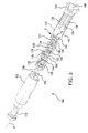
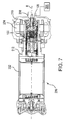
- Fig. 1 a partial view of an exemplary embodiment of a rectifier in accordance with the disclosure is shown in Fig. 1 and is designated generally by reference character 100.
- the systems and methods described herein can be for electrical generators, such as aircraft main engine and auxiliary power unit generators.
- Rectifier 100 includes a housing 102 with an input end 104 and an output end 106.
- Housing 102 defines a rotation axis R and a transfer tube bushing 108 with a coolant supply aperture disposed centrally and along rotation axis R.
- Transfer tube bushing 108 is configured to seat an oil transfer tube 208 (shown in Fig. 7 ) for receiving a coolant flow within housing 102, such as from a lubrication circuit 206 (also shown in Fig. 7 ) of a gas turbine engine.
- the coolant like lubricant (e.g. oil), enters input end 104, traverses components disposed within housing 102, and exits housing 102 through output end 106.
- lubricant e.g. oil
- Input end 104 may include a plurality of alternating current (AC) electrical power input leads, and as illustrated includes a first AC terminal 110, a second AC terminal 112, and a third AC terminal 114.
- Output end 106 may include a positive direct current (DC) lead 116 and a negative DC lead 118 (shown in Fig. 2 ).
- DC direct current
- Rectifier circuit 120 is disposed within an interior of housing 102 and includes a plurality of diodes and diode plates arranged along rotation axis R of rectifier 100. As illustrated, rectifier 100 includes five bus bars, six diodes, eight diode plates, and a resistor electrically connected with one another to form rectifier circuit 120. Each of the six diodes includes axially opposed anode and cathode faces, indicated with positive and negative symbols in Fig. 2 , and which are coaxial with one another and angled relative to rotation axis R.
- the five bus bars of rectifier circuit 120 include three AC bus bars, each carrying separate AC phases, and two DC bus bars.
- rectifier 100 includes a first AC bus bar 134 connected to first AC terminal 110, a second AC bus bar 136 connected to second AC terminal 112, and a third AC bus bar 138 connected to third AC terminal 114.
- Rectifier 100 also includes a positive DC bus bar 140 connected to positive DC terminal 116 and a negative DC bus bar 142 connected to negative DC terminal 118.
- the six diodes of rectifier circuit 120 include a first diode 122, a second diode 124, a third diode 126, a fourth diode 128, a fifth diode 130, and a sixth diode 132.
- Each of the six diodes is electrically interconnected with one another within a rectification circuit between one of the plurality of bus bars, i.e. first AC bus bar 134, second AC bus bar 136, third AC bus bar 138, positive DC bus bar 140, and negative bus bar 142, for rectifying AC electrical power received at the AC terminals, i.e. first AC terminal 110, second AC terminal 112, and third AC terminal 114, into DC electrical power.
- the rectification circuit thereafter provides the DC electrical power to positive DC terminal 116 and negative DC terminal 118 for on-rotor use.
- the eight diode plates of rectifier circuit 120 include a first diode plate 144, a second diode plate 146, a third diode plate 148, a fourth diode plate 150, a fifth diode plate 152, a sixth diode plate 154, a seventh diode plate 155, and an eighth diode plate 156.
- First diode plate 144 electrically connects an anode face of first diode 122 with positive DC us bar 140.
- Second diode plate 146 is disposed between first diode 122 and second diode 124, and electrically interconnects both a cathode face of first diode 122 and an anode face of second diode 124 with first AC bus bar 134.
- Third diode plate 148 is disposed between second diode 124 and third diode 126, and electrically interconnects both a cathode face of second diode 124 and a cathode face of third diode 126 with negative DC bus bar 142.
- Fourth diode plate 150 is disposed between third diode 126 and fourth diode 128, and electrically interconnects both an anode face of third diode 126 and a cathode face of fourth diode 128 with second AC bus bar 136.
- Fifth diode plate 152 is disposed between fourth diode 128 and fifth diode 130, and electrically interconnects both an anode face of fourth diode 128 and an anode face of fifth diode 130 with positive DC bus bar 140.
- Sixth diode plate 154 is disposed between fifth diode 130 and sixth diode 132, and electrically interconnects both a cathode face of fifth diode 130 and an anode face of sixth diode 132 with third AC bus bar 138.
- a resistor 158 electrically connected in series with a seventh diode plate 155 connects a cathode face of sixth diode 132 with negative DC bus bar 142 and eighth diode plate 156 connects resistor 158 with positive DC bus bar 140.
- rectifier circuit 120 generates heat while rectifying input AC electrical power into DC electrical power.
- a generator e.g. generator 200 (shown in Fig. 7 ) provides a flow of coolant to rectifier 100 for purposes of cooling rectifier circuit 120 while rectifying AC electrical power into DC electrical power.
- coolant provided to generator 200 enters rectifier 100 through a coolant aperture defined by transfer tube bushing 108 (shown in Fig. 1 ), flows across surfaces of the plurality of diodes and other components disposed within housing 102, and exits housing 102 through output end 106.
- transfer tube bushing 108 shown in Fig. 1
- Fluids with low electrical conductivity such as certain types of lubricants and oils, can acquire a space charge as the fluid flows across a solid surface due to the frictional charge separation that occurs at the liquid-solid interface.
- the space charge developed can be transported by the fluid flow, forming a streaming current in the liquid flow.
- Lubricant filters for example, can be sources of streaming charge generation due to the shearing action that occurs within the filter.
- this flow electrification process can cause electrostatic charge to accumulate and potentially generate electrostatic surface potential at liquid-solid interfaces of magnitude sufficient to damage the electrical structure(s) during a discharge event.
- charge accumulation can exceed the rotor circuit dielectric capability, and discharge can occurs.
- the capacitive effects of the rotor circuit insulation can produce a large reverse bias across the diodes, potentially causing the diode to fail.
- Rectifier 100 is electrically grounded, thereby limiting electrostatic charge accumulation to below levels where discharge events can potentially damage circuit components.
- rectifier 100 includes a transfer tube bushing 108 that electrically connects to positive DC bus bar 140. The electrical connection grounds rectifier circuit 120 through transfer tube bushing 108 and positive DC bus bar 140, thereby providing a path for accumulated electrostatic charge to ground, and enables control of electrostatic discharge events. This prevents electrostatic of discharge of magnitude sufficient to damage components of rectifier circuit 120, such as could otherwise be possible - particularly following an engine lubricant change where static charge accumulation can be significant. Examples of suitable grounding schemes can be found in U.S. Patent No. 8,063,522 .
- Each diode includes an anode face A and a cathode face C.
- Anode face A and cathode face C are each angled with respect to rotation axis R, and as illustrated are angled at about a 90-degree angle relative to rotation axis R.
- suitable diodes are dual-face diodes sold under the trade name PowerEx ® , and are available from PowerEx, Inc. of Youngwood, Pennsylvania.
- Each diode plate, i.e. diode plates 144-156 includes a plate-like body B and an axially-extending key D. Please-like body B overlays the face of axially adjacent diode(s), and key D provides electrical connectivity to one of the AC or DC bus bars, i.e. bus bars 134-144.
- rectifier 100 is shown in cross-section.
- Key D of first diode plate 144 has an axial length 170 that is greater than an axial height 172 of first diode 122.
- First diode plate 144 also axially overlaps second diode plate 146.
- Second diode plate 146 is rotationally offset relative to rotation axis such that first diode plate 144 is nested with second diode plate 146, thereby providing an axially compact structure.
- the axially compact structure provided by the nested arrangement of the diode plates and intervening diode reduces the contact area between the diode and lubricant flowing through rectifier 100, reducing the amount of surface area exposed to the static charge-carrying lubricant.
- first diode plate 144 also axially overlaps and nests with third diode plate 148.
- rectifier 100 includes six diodes (122-132), eight diode plates (144-156), a plurality of diode retainers 184, and a diode pivot 176.
- the diodes, i.e. diodes 122-132, are each axially stacked in relation to one another.
- Respective diode retainers 184 circumferentially surround each diode between respective pairs of axially adjacent diode plates.
- the diode plates, i.e. diode plates 144-156 are axially stacked with one another and nested with one another such that seven of the diode plates overlap and nest with one another.
- Diode plates 144-156 are also circumferentially clocked with respect to one another about rotation axis R such that each diode plate both is electrically connected with a bus bars and nests with an axially adjacent diode plate.
- Diode pivot 176 is an electrically passive component, and can therefore be lengthened or shortened in relation to housing 102 such that housing 102 can fit into rotor assembly 200 (shown in Fig;. 7 ) without altering the shape of the cavity seating rectifier 100. This can be done, for example, by increasing an axial length of either or both of diode pivot 176 and resistor 158, and without modifying rotor assembly 200.
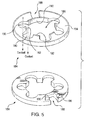
- diode retainer 184 includes a retainer body 194.
- Retainer body 194 defines a central aperture 186 for seating a diode, a keyway 188 for seating and circumferentially locking a diode plate, and a plurality of flow apertures 190.
- Central aperture 186 is bounded by a plurality of circumferentially adjacent diode surfaces 192 for fixing a diode within diode retainer 184.
- Flow apertures 190 include suitably sized flow apertures for allowing coolant to flow through rectifier 100 (shown in Fig. 1 ), along rotation axis R (shown in Fig. 1 ), and off-axis for purposes of cooling diodes disposed therein.
- Barrier wall 196 is adjacent to keyway 188 and electrically insulates the diode plates from one another in the radial direction.
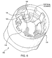
- first end 104 is shown with oil transfer tube bushing 108 removed.
- First diode plate 144 is clocked relative to second diode plate 146 by a radially extending wedge profile of barrier wall 196.
- the width of barrier wall 196 at its radially inner end defines the electrical clearance between first diode plate 144 and second diode plate 146, physically separating first diode plate 144 from second diode plate 146 such that each is electrically isolated from one another within a predetermined potential difference limit. This prevents internal shorting within rectifier 100.
- Generator 200 includes a rotor assembly 202 rotatably disposed in relation to a stator assembly 204.
- Rotor assembly 202 includes a hollow shaft 212 that seats within its interior rectifier 100 having a diode pack as described above.
- Stator assembly 204 includes a lubrication circuit 206 that is in fluid communication rectifier 100 and the rectifier diode pack through an oil transfer tube 208.
- Transfer tube 208 seats within transfer tube bushing 108, is rotatable relative transfer tube bushing 108, and is configured to a flow of lubricant from lubrication circuit 206 through oil transfer tube 208 for purposes of cooling the diode pack disposed within rectifier 100.
Landscapes
- Engineering & Computer Science (AREA)
- Power Engineering (AREA)
Applications Claiming Priority (1)
| Application Number | Priority Date | Filing Date | Title |
|---|---|---|---|
| US14/611,971 US9912213B2 (en) | 2015-02-02 | 2015-02-02 | Rotating rectifiers with nested diodes |
Publications (2)
| Publication Number | Publication Date |
|---|---|
| EP3051673A1 true EP3051673A1 (fr) | 2016-08-03 |
| EP3051673B1 EP3051673B1 (fr) | 2017-08-23 |
Family
ID=55304880
Family Applications (1)
| Application Number | Title | Priority Date | Filing Date |
|---|---|---|---|
| EP16153948.1A Active EP3051673B1 (fr) | 2015-02-02 | 2016-02-02 | Redresseurs tournants avec des diodes intégrées |
Country Status (2)
| Country | Link |
|---|---|
| US (1) | US9912213B2 (fr) |
| EP (1) | EP3051673B1 (fr) |
Families Citing this family (7)
| Publication number | Priority date | Publication date | Assignee | Title |
|---|---|---|---|---|
| US11764648B2 (en) * | 2020-12-07 | 2023-09-19 | Hamilton Sundstrand Corporation | Rotating rectifiers |
| US11949294B2 (en) | 2021-03-13 | 2024-04-02 | Hamilton Sundstrand Corporation | Resistor plate assembly with contact bands |
| US12009126B2 (en) | 2021-03-13 | 2024-06-11 | Hamilton Sundstrand Corporation | Resistor support assembly with spring seat |
| US11799391B2 (en) * | 2021-03-13 | 2023-10-24 | Hamilton Sundstrand Corporation | Diode mounting ring with contact band inserts |
| CN113489346B (zh) * | 2021-06-09 | 2022-06-14 | 中国科学院电工研究所 | 适用于高速大电流的旋转整流器 |
| CN115514162A (zh) * | 2022-09-30 | 2022-12-23 | 陕西航空电气有限责任公司 | 一种航空油冷电机用旋转整流组件 |
| US20240341059A1 (en) * | 2023-04-05 | 2024-10-10 | Hamilton Sundstrand Corporation | Rectifier diode assembly |
Citations (6)
| Publication number | Priority date | Publication date | Assignee | Title |
|---|---|---|---|---|
| WO1986001035A1 (fr) * | 1984-07-30 | 1986-02-13 | Sundstrand Corporation | Ensemble de redressement rotatif |
| US4621210A (en) * | 1985-11-22 | 1986-11-04 | Sundstrand Corporation | Electric generator cooling arrangement |
| US4628219A (en) * | 1985-09-13 | 1986-12-09 | Sundstrand Corporation | Rectifier assembly for mounting in a rotor |
| US4745315A (en) * | 1983-12-15 | 1988-05-17 | General Electric Company | Brushless exciter with zero-gravity rectifier assembly |
| US5065484A (en) * | 1989-04-14 | 1991-11-19 | Sundstrand Corporation | Rotating rectifier assembly |
| US8063522B2 (en) | 2009-09-14 | 2011-11-22 | Hamilton Sundstrand Corporation | Generator rotor ground bushing |
Family Cites Families (2)
| Publication number | Priority date | Publication date | Assignee | Title |
|---|---|---|---|---|
| US4827165A (en) * | 1987-11-16 | 1989-05-02 | Sundstrand Corporation | Integrated diode package |
| US5796196A (en) * | 1996-08-26 | 1998-08-18 | Sundstrand Corporation | Adaptable rotating rectifier and suppression resistor assembly for two-pole, wound rotor of dynamoelectric machine |
-
2015
- 2015-02-02 US US14/611,971 patent/US9912213B2/en active Active
-
2016
- 2016-02-02 EP EP16153948.1A patent/EP3051673B1/fr active Active
Patent Citations (6)
| Publication number | Priority date | Publication date | Assignee | Title |
|---|---|---|---|---|
| US4745315A (en) * | 1983-12-15 | 1988-05-17 | General Electric Company | Brushless exciter with zero-gravity rectifier assembly |
| WO1986001035A1 (fr) * | 1984-07-30 | 1986-02-13 | Sundstrand Corporation | Ensemble de redressement rotatif |
| US4628219A (en) * | 1985-09-13 | 1986-12-09 | Sundstrand Corporation | Rectifier assembly for mounting in a rotor |
| US4621210A (en) * | 1985-11-22 | 1986-11-04 | Sundstrand Corporation | Electric generator cooling arrangement |
| US5065484A (en) * | 1989-04-14 | 1991-11-19 | Sundstrand Corporation | Rotating rectifier assembly |
| US8063522B2 (en) | 2009-09-14 | 2011-11-22 | Hamilton Sundstrand Corporation | Generator rotor ground bushing |
Also Published As
| Publication number | Publication date |
|---|---|
| EP3051673B1 (fr) | 2017-08-23 |
| US20160226348A1 (en) | 2016-08-04 |
| US9912213B2 (en) | 2018-03-06 |
Similar Documents
| Publication | Publication Date | Title |
|---|---|---|
| EP3051673B1 (fr) | Redresseurs tournants avec des diodes intégrées | |
| CN105637744B (zh) | 用于电机的转子组件 | |
| EP2369723A2 (fr) | Agencement de refroidisseur pour machine électrique | |
| CN103633751A (zh) | 具有由多个可分离段形成的定子和转子圆盘的轴向空气间隙机 | |
| EP2770615B1 (fr) | Procédé et ensemble de redressement rotatif | |
| US9369029B2 (en) | Rotating rectifier assembly for electric machine | |
| US10826345B2 (en) | Conductor and method of forming thereof | |
| CN112311147A (zh) | 电机 | |
| KR102861506B1 (ko) | 전기 구동 유닛 | |
| EP3599704B1 (fr) | Ensemble stator | |
| US20160013707A1 (en) | Rotating rectifier assembly for electric machine | |
| EP3713051B1 (fr) | Ensemble rotor et son procédé de refroidissement | |
| US11038403B2 (en) | Rotary electric machines and methods of cooling rotary electric machines | |
| CN117296235B (zh) | 电驱动单元 | |
| US4827165A (en) | Integrated diode package | |
| US20140239778A1 (en) | Rotating rectifier assembly and method | |
| EP3654500A1 (fr) | Appareil et procédé de refroidissement de bobines d'extrémité dans une machine électrique rotative | |
| US20240055951A1 (en) | Induction rotor with end ring cooling features | |
| EP2866333B1 (fr) | Ensemble de redressement rotatif et méthode de fabrication | |
| EP3154161A1 (fr) | Rotor de machine électrique tournante | |
| US11695346B2 (en) | Inverter device | |
| CN110784048B (zh) | 定子组件 | |
| EP4443713A1 (fr) | Machine électrique dotée d'un ensemble de retenue de fil | |
| WO2025188556A1 (fr) | Machine électrique et système de refroidissement pour une machine électrique | |
| WO2026019411A1 (fr) | Refroidissement de stator axial pourvu d'un segment de plaque, anneau stratifié et stratifié |
Legal Events
| Date | Code | Title | Description |
|---|---|---|---|
| PUAI | Public reference made under article 153(3) epc to a published international application that has entered the european phase |
Free format text: ORIGINAL CODE: 0009012 |
|
| AK | Designated contracting states |
Kind code of ref document: A1 Designated state(s): AL AT BE BG CH CY CZ DE DK EE ES FI FR GB GR HR HU IE IS IT LI LT LU LV MC MK MT NL NO PL PT RO RS SE SI SK SM TR |
|
| AX | Request for extension of the european patent |
Extension state: BA ME |
|
| STAA | Information on the status of an ep patent application or granted ep patent |
Free format text: STATUS: REQUEST FOR EXAMINATION WAS MADE |
|
| 17P | Request for examination filed |
Effective date: 20170202 |
|
| RBV | Designated contracting states (corrected) |
Designated state(s): AL AT BE BG CH CY CZ DE DK EE ES FI FR GB GR HR HU IE IS IT LI LT LU LV MC MK MT NL NO PL PT RO RS SE SI SK SM TR |
|
| GRAP | Despatch of communication of intention to grant a patent |
Free format text: ORIGINAL CODE: EPIDOSNIGR1 |
|
| STAA | Information on the status of an ep patent application or granted ep patent |
Free format text: STATUS: GRANT OF PATENT IS INTENDED |
|
| RIC1 | Information provided on ipc code assigned before grant |
Ipc: H02K 11/042 20160101AFI20170224BHEP |
|
| INTG | Intention to grant announced |
Effective date: 20170317 |
|
| GRAS | Grant fee paid |
Free format text: ORIGINAL CODE: EPIDOSNIGR3 |
|
| GRAA | (expected) grant |
Free format text: ORIGINAL CODE: 0009210 |
|
| STAA | Information on the status of an ep patent application or granted ep patent |
Free format text: STATUS: THE PATENT HAS BEEN GRANTED |
|
| AK | Designated contracting states |
Kind code of ref document: B1 Designated state(s): AL AT BE BG CH CY CZ DE DK EE ES FI FR GB GR HR HU IE IS IT LI LT LU LV MC MK MT NL NO PL PT RO RS SE SI SK SM TR |
|
| REG | Reference to a national code |
Ref country code: GB Ref legal event code: FG4D |
|
| REG | Reference to a national code |
Ref country code: CH Ref legal event code: EP |
|
| REG | Reference to a national code |
Ref country code: AT Ref legal event code: REF Ref document number: 922306 Country of ref document: AT Kind code of ref document: T Effective date: 20170915 |
|
| REG | Reference to a national code |
Ref country code: IE Ref legal event code: FG4D |
|
| REG | Reference to a national code |
Ref country code: DE Ref legal event code: R096 Ref document number: 602016000255 Country of ref document: DE |
|
| REG | Reference to a national code |
Ref country code: NL Ref legal event code: MP Effective date: 20170823 |
|
| REG | Reference to a national code |
Ref country code: LT Ref legal event code: MG4D |
|
| REG | Reference to a national code |
Ref country code: AT Ref legal event code: MK05 Ref document number: 922306 Country of ref document: AT Kind code of ref document: T Effective date: 20170823 |
|
| REG | Reference to a national code |
Ref country code: FR Ref legal event code: PLFP Year of fee payment: 3 |
|
| PG25 | Lapsed in a contracting state [announced via postgrant information from national office to epo] |
Ref country code: NO Free format text: LAPSE BECAUSE OF FAILURE TO SUBMIT A TRANSLATION OF THE DESCRIPTION OR TO PAY THE FEE WITHIN THE PRESCRIBED TIME-LIMIT Effective date: 20171123 Ref country code: AT Free format text: LAPSE BECAUSE OF FAILURE TO SUBMIT A TRANSLATION OF THE DESCRIPTION OR TO PAY THE FEE WITHIN THE PRESCRIBED TIME-LIMIT Effective date: 20170823 Ref country code: SE Free format text: LAPSE BECAUSE OF FAILURE TO SUBMIT A TRANSLATION OF THE DESCRIPTION OR TO PAY THE FEE WITHIN THE PRESCRIBED TIME-LIMIT Effective date: 20170823 Ref country code: NL Free format text: LAPSE BECAUSE OF FAILURE TO SUBMIT A TRANSLATION OF THE DESCRIPTION OR TO PAY THE FEE WITHIN THE PRESCRIBED TIME-LIMIT Effective date: 20170823 Ref country code: FI Free format text: LAPSE BECAUSE OF FAILURE TO SUBMIT A TRANSLATION OF THE DESCRIPTION OR TO PAY THE FEE WITHIN THE PRESCRIBED TIME-LIMIT Effective date: 20170823 Ref country code: HR Free format text: LAPSE BECAUSE OF FAILURE TO SUBMIT A TRANSLATION OF THE DESCRIPTION OR TO PAY THE FEE WITHIN THE PRESCRIBED TIME-LIMIT Effective date: 20170823 Ref country code: LT Free format text: LAPSE BECAUSE OF FAILURE TO SUBMIT A TRANSLATION OF THE DESCRIPTION OR TO PAY THE FEE WITHIN THE PRESCRIBED TIME-LIMIT Effective date: 20170823 |
|
| PG25 | Lapsed in a contracting state [announced via postgrant information from national office to epo] |
Ref country code: PL Free format text: LAPSE BECAUSE OF FAILURE TO SUBMIT A TRANSLATION OF THE DESCRIPTION OR TO PAY THE FEE WITHIN THE PRESCRIBED TIME-LIMIT Effective date: 20170823 Ref country code: BG Free format text: LAPSE BECAUSE OF FAILURE TO SUBMIT A TRANSLATION OF THE DESCRIPTION OR TO PAY THE FEE WITHIN THE PRESCRIBED TIME-LIMIT Effective date: 20171123 Ref country code: RS Free format text: LAPSE BECAUSE OF FAILURE TO SUBMIT A TRANSLATION OF THE DESCRIPTION OR TO PAY THE FEE WITHIN THE PRESCRIBED TIME-LIMIT Effective date: 20170823 Ref country code: IS Free format text: LAPSE BECAUSE OF FAILURE TO SUBMIT A TRANSLATION OF THE DESCRIPTION OR TO PAY THE FEE WITHIN THE PRESCRIBED TIME-LIMIT Effective date: 20171223 Ref country code: GR Free format text: LAPSE BECAUSE OF FAILURE TO SUBMIT A TRANSLATION OF THE DESCRIPTION OR TO PAY THE FEE WITHIN THE PRESCRIBED TIME-LIMIT Effective date: 20171124 Ref country code: ES Free format text: LAPSE BECAUSE OF FAILURE TO SUBMIT A TRANSLATION OF THE DESCRIPTION OR TO PAY THE FEE WITHIN THE PRESCRIBED TIME-LIMIT Effective date: 20170823 Ref country code: LV Free format text: LAPSE BECAUSE OF FAILURE TO SUBMIT A TRANSLATION OF THE DESCRIPTION OR TO PAY THE FEE WITHIN THE PRESCRIBED TIME-LIMIT Effective date: 20170823 |
|
| PG25 | Lapsed in a contracting state [announced via postgrant information from national office to epo] |
Ref country code: CZ Free format text: LAPSE BECAUSE OF FAILURE TO SUBMIT A TRANSLATION OF THE DESCRIPTION OR TO PAY THE FEE WITHIN THE PRESCRIBED TIME-LIMIT Effective date: 20170823 Ref country code: DK Free format text: LAPSE BECAUSE OF FAILURE TO SUBMIT A TRANSLATION OF THE DESCRIPTION OR TO PAY THE FEE WITHIN THE PRESCRIBED TIME-LIMIT Effective date: 20170823 Ref country code: RO Free format text: LAPSE BECAUSE OF FAILURE TO SUBMIT A TRANSLATION OF THE DESCRIPTION OR TO PAY THE FEE WITHIN THE PRESCRIBED TIME-LIMIT Effective date: 20170823 |
|
| REG | Reference to a national code |
Ref country code: DE Ref legal event code: R097 Ref document number: 602016000255 Country of ref document: DE |
|
| PG25 | Lapsed in a contracting state [announced via postgrant information from national office to epo] |
Ref country code: IT Free format text: LAPSE BECAUSE OF FAILURE TO SUBMIT A TRANSLATION OF THE DESCRIPTION OR TO PAY THE FEE WITHIN THE PRESCRIBED TIME-LIMIT Effective date: 20170823 Ref country code: SM Free format text: LAPSE BECAUSE OF FAILURE TO SUBMIT A TRANSLATION OF THE DESCRIPTION OR TO PAY THE FEE WITHIN THE PRESCRIBED TIME-LIMIT Effective date: 20170823 Ref country code: SK Free format text: LAPSE BECAUSE OF FAILURE TO SUBMIT A TRANSLATION OF THE DESCRIPTION OR TO PAY THE FEE WITHIN THE PRESCRIBED TIME-LIMIT Effective date: 20170823 Ref country code: EE Free format text: LAPSE BECAUSE OF FAILURE TO SUBMIT A TRANSLATION OF THE DESCRIPTION OR TO PAY THE FEE WITHIN THE PRESCRIBED TIME-LIMIT Effective date: 20170823 |
|
| PLBE | No opposition filed within time limit |
Free format text: ORIGINAL CODE: 0009261 |
|
| STAA | Information on the status of an ep patent application or granted ep patent |
Free format text: STATUS: NO OPPOSITION FILED WITHIN TIME LIMIT |
|
| 26N | No opposition filed |
Effective date: 20180524 |
|
| PG25 | Lapsed in a contracting state [announced via postgrant information from national office to epo] |
Ref country code: SI Free format text: LAPSE BECAUSE OF FAILURE TO SUBMIT A TRANSLATION OF THE DESCRIPTION OR TO PAY THE FEE WITHIN THE PRESCRIBED TIME-LIMIT Effective date: 20170823 |
|
| REG | Reference to a national code |
Ref country code: DE Ref legal event code: R119 Ref document number: 602016000255 Country of ref document: DE |
|
| PG25 | Lapsed in a contracting state [announced via postgrant information from national office to epo] |
Ref country code: MC Free format text: LAPSE BECAUSE OF FAILURE TO SUBMIT A TRANSLATION OF THE DESCRIPTION OR TO PAY THE FEE WITHIN THE PRESCRIBED TIME-LIMIT Effective date: 20170823 |
|
| REG | Reference to a national code |
Ref country code: IE Ref legal event code: MM4A |
|
| REG | Reference to a national code |
Ref country code: BE Ref legal event code: MM Effective date: 20180228 |
|
| PG25 | Lapsed in a contracting state [announced via postgrant information from national office to epo] |
Ref country code: LU Free format text: LAPSE BECAUSE OF NON-PAYMENT OF DUE FEES Effective date: 20180202 |
|
| PG25 | Lapsed in a contracting state [announced via postgrant information from national office to epo] |
Ref country code: IE Free format text: LAPSE BECAUSE OF NON-PAYMENT OF DUE FEES Effective date: 20180202 Ref country code: DE Free format text: LAPSE BECAUSE OF NON-PAYMENT OF DUE FEES Effective date: 20180901 |
|
| PG25 | Lapsed in a contracting state [announced via postgrant information from national office to epo] |
Ref country code: BE Free format text: LAPSE BECAUSE OF NON-PAYMENT OF DUE FEES Effective date: 20180228 |
|
| REG | Reference to a national code |
Ref country code: CH Ref legal event code: PL |
|
| PG25 | Lapsed in a contracting state [announced via postgrant information from national office to epo] |
Ref country code: LI Free format text: LAPSE BECAUSE OF NON-PAYMENT OF DUE FEES Effective date: 20190228 Ref country code: CH Free format text: LAPSE BECAUSE OF NON-PAYMENT OF DUE FEES Effective date: 20190228 |
|
| PG25 | Lapsed in a contracting state [announced via postgrant information from national office to epo] |
Ref country code: MT Free format text: LAPSE BECAUSE OF NON-PAYMENT OF DUE FEES Effective date: 20180202 |
|
| PG25 | Lapsed in a contracting state [announced via postgrant information from national office to epo] |
Ref country code: TR Free format text: LAPSE BECAUSE OF FAILURE TO SUBMIT A TRANSLATION OF THE DESCRIPTION OR TO PAY THE FEE WITHIN THE PRESCRIBED TIME-LIMIT Effective date: 20170823 |
|
| PG25 | Lapsed in a contracting state [announced via postgrant information from national office to epo] |
Ref country code: PT Free format text: LAPSE BECAUSE OF FAILURE TO SUBMIT A TRANSLATION OF THE DESCRIPTION OR TO PAY THE FEE WITHIN THE PRESCRIBED TIME-LIMIT Effective date: 20170823 |
|
| PG25 | Lapsed in a contracting state [announced via postgrant information from national office to epo] |
Ref country code: MK Free format text: LAPSE BECAUSE OF NON-PAYMENT OF DUE FEES Effective date: 20170823 Ref country code: CY Free format text: LAPSE BECAUSE OF FAILURE TO SUBMIT A TRANSLATION OF THE DESCRIPTION OR TO PAY THE FEE WITHIN THE PRESCRIBED TIME-LIMIT Effective date: 20170823 Ref country code: HU Free format text: LAPSE BECAUSE OF FAILURE TO SUBMIT A TRANSLATION OF THE DESCRIPTION OR TO PAY THE FEE WITHIN THE PRESCRIBED TIME-LIMIT; INVALID AB INITIO Effective date: 20160202 |
|
| PG25 | Lapsed in a contracting state [announced via postgrant information from national office to epo] |
Ref country code: AL Free format text: LAPSE BECAUSE OF FAILURE TO SUBMIT A TRANSLATION OF THE DESCRIPTION OR TO PAY THE FEE WITHIN THE PRESCRIBED TIME-LIMIT Effective date: 20170823 |
|
| P01 | Opt-out of the competence of the unified patent court (upc) registered |
Effective date: 20230522 |
|
| PGFP | Annual fee paid to national office [announced via postgrant information from national office to epo] |
Ref country code: FR Payment date: 20250121 Year of fee payment: 10 |
|
| PGFP | Annual fee paid to national office [announced via postgrant information from national office to epo] |
Ref country code: GB Payment date: 20250124 Year of fee payment: 10 |