EP3051646A1 - Système d'alimentation en courant continu - Google Patents
Système d'alimentation en courant continu Download PDFInfo
- Publication number
- EP3051646A1 EP3051646A1 EP16152390.7A EP16152390A EP3051646A1 EP 3051646 A1 EP3051646 A1 EP 3051646A1 EP 16152390 A EP16152390 A EP 16152390A EP 3051646 A1 EP3051646 A1 EP 3051646A1
- Authority
- EP
- European Patent Office
- Prior art keywords
- rail
- bus
- positive
- negative
- inductor
- Prior art date
- Legal status (The legal status is an assumption and is not a legal conclusion. Google has not performed a legal analysis and makes no representation as to the accuracy of the status listed.)
- Granted
Links
- 238000000034 method Methods 0.000 claims description 18
- 230000002457 bidirectional effect Effects 0.000 claims description 7
- 239000003990 capacitor Substances 0.000 claims description 6
- 238000012546 transfer Methods 0.000 abstract description 5
- 230000008878 coupling Effects 0.000 description 9
- 238000010168 coupling process Methods 0.000 description 9
- 238000005859 coupling reaction Methods 0.000 description 9
- 238000010586 diagram Methods 0.000 description 7
- 238000000926 separation method Methods 0.000 description 4
- 230000005540 biological transmission Effects 0.000 description 3
- 238000006243 chemical reaction Methods 0.000 description 2
- 238000004146 energy storage Methods 0.000 description 2
- 230000005669 field effect Effects 0.000 description 2
- 238000012986 modification Methods 0.000 description 2
- 230000004048 modification Effects 0.000 description 2
- 239000003921 oil Substances 0.000 description 2
- 239000004065 semiconductor Substances 0.000 description 2
- 238000004088 simulation Methods 0.000 description 2
- 239000000243 solution Substances 0.000 description 2
- JBRZTFJDHDCESZ-UHFFFAOYSA-N AsGa Chemical compound [As]#[Ga] JBRZTFJDHDCESZ-UHFFFAOYSA-N 0.000 description 1
- 229910002601 GaN Inorganic materials 0.000 description 1
- 229910001218 Gallium arsenide Inorganic materials 0.000 description 1
- JMASRVWKEDWRBT-UHFFFAOYSA-N Gallium nitride Chemical compound [Ga]#N JMASRVWKEDWRBT-UHFFFAOYSA-N 0.000 description 1
- 239000006096 absorbing agent Substances 0.000 description 1
- 238000004378 air conditioning Methods 0.000 description 1
- 230000003247 decreasing effect Effects 0.000 description 1
- 238000013461 design Methods 0.000 description 1
- 238000009826 distribution Methods 0.000 description 1
- 238000005516 engineering process Methods 0.000 description 1
- 238000002347 injection Methods 0.000 description 1
- 239000007924 injection Substances 0.000 description 1
- 238000009434 installation Methods 0.000 description 1
- 238000002955 isolation Methods 0.000 description 1
- 238000012423 maintenance Methods 0.000 description 1
- 238000004519 manufacturing process Methods 0.000 description 1
- 229910044991 metal oxide Inorganic materials 0.000 description 1
- 150000004706 metal oxides Chemical class 0.000 description 1
- 230000003134 recirculating effect Effects 0.000 description 1
- HBMJWWWQQXIZIP-UHFFFAOYSA-N silicon carbide Chemical compound [Si+]#[C-] HBMJWWWQQXIZIP-UHFFFAOYSA-N 0.000 description 1
- 229910010271 silicon carbide Inorganic materials 0.000 description 1
Images


Classifications
-
- H—ELECTRICITY
- H02—GENERATION; CONVERSION OR DISTRIBUTION OF ELECTRIC POWER
- H02J—CIRCUIT ARRANGEMENTS OR SYSTEMS FOR SUPPLYING OR DISTRIBUTING ELECTRIC POWER; SYSTEMS FOR STORING ELECTRIC ENERGY
- H02J3/00—Circuit arrangements for ac mains or ac distribution networks
- H02J3/38—Arrangements for parallely feeding a single network by two or more generators, converters or transformers
- H02J3/381—Dispersed generators
-
- H—ELECTRICITY
- H02—GENERATION; CONVERSION OR DISTRIBUTION OF ELECTRIC POWER
- H02H—EMERGENCY PROTECTIVE CIRCUIT ARRANGEMENTS
- H02H7/00—Emergency protective circuit arrangements specially adapted for specific types of electric machines or apparatus or for sectionalised protection of cable or line systems, and effecting automatic switching in the event of an undesired change from normal working conditions
- H02H7/26—Sectionalised protection of cable or line systems, e.g. for disconnecting a section on which a short-circuit, earth fault, or arc discharge has occured
- H02H7/261—Sectionalised protection of cable or line systems, e.g. for disconnecting a section on which a short-circuit, earth fault, or arc discharge has occured involving signal transmission between at least two stations
- H02H7/262—Sectionalised protection of cable or line systems, e.g. for disconnecting a section on which a short-circuit, earth fault, or arc discharge has occured involving signal transmission between at least two stations involving transmissions of switching or blocking orders
-
- H—ELECTRICITY
- H02—GENERATION; CONVERSION OR DISTRIBUTION OF ELECTRIC POWER
- H02H—EMERGENCY PROTECTIVE CIRCUIT ARRANGEMENTS
- H02H7/00—Emergency protective circuit arrangements specially adapted for specific types of electric machines or apparatus or for sectionalised protection of cable or line systems, and effecting automatic switching in the event of an undesired change from normal working conditions
- H02H7/26—Sectionalised protection of cable or line systems, e.g. for disconnecting a section on which a short-circuit, earth fault, or arc discharge has occured
- H02H7/267—Sectionalised protection of cable or line systems, e.g. for disconnecting a section on which a short-circuit, earth fault, or arc discharge has occured for parallel lines and wires
-
- H—ELECTRICITY
- H02—GENERATION; CONVERSION OR DISTRIBUTION OF ELECTRIC POWER
- H02H—EMERGENCY PROTECTIVE CIRCUIT ARRANGEMENTS
- H02H7/00—Emergency protective circuit arrangements specially adapted for specific types of electric machines or apparatus or for sectionalised protection of cable or line systems, and effecting automatic switching in the event of an undesired change from normal working conditions
- H02H7/26—Sectionalised protection of cable or line systems, e.g. for disconnecting a section on which a short-circuit, earth fault, or arc discharge has occured
- H02H7/268—Sectionalised protection of cable or line systems, e.g. for disconnecting a section on which a short-circuit, earth fault, or arc discharge has occured for dc systems
-
- H—ELECTRICITY
- H02—GENERATION; CONVERSION OR DISTRIBUTION OF ELECTRIC POWER
- H02H—EMERGENCY PROTECTIVE CIRCUIT ARRANGEMENTS
- H02H9/00—Emergency protective circuit arrangements for limiting excess current or voltage without disconnection
- H02H9/02—Emergency protective circuit arrangements for limiting excess current or voltage without disconnection responsive to excess current
- H02H9/021—Current limitation using saturable reactors
-
- H—ELECTRICITY
- H02—GENERATION; CONVERSION OR DISTRIBUTION OF ELECTRIC POWER
- H02J—CIRCUIT ARRANGEMENTS OR SYSTEMS FOR SUPPLYING OR DISTRIBUTING ELECTRIC POWER; SYSTEMS FOR STORING ELECTRIC ENERGY
- H02J1/00—Circuit arrangements for dc mains or dc distribution networks
- H02J1/10—Parallel operation of dc sources
-
- H—ELECTRICITY
- H03—ELECTRONIC CIRCUITRY
- H03K—PULSE TECHNIQUE
- H03K17/00—Electronic switching or gating, i.e. not by contact-making and –breaking
- H03K17/08—Modifications for protecting switching circuit against overcurrent or overvoltage
-
- H—ELECTRICITY
- H02—GENERATION; CONVERSION OR DISTRIBUTION OF ELECTRIC POWER
- H02H—EMERGENCY PROTECTIVE CIRCUIT ARRANGEMENTS
- H02H3/00—Emergency protective circuit arrangements for automatic disconnection directly responsive to an undesired change from normal electric working condition with or without subsequent reconnection ; integrated protection
- H02H3/08—Emergency protective circuit arrangements for automatic disconnection directly responsive to an undesired change from normal electric working condition with or without subsequent reconnection ; integrated protection responsive to excess current
- H02H3/087—Emergency protective circuit arrangements for automatic disconnection directly responsive to an undesired change from normal electric working condition with or without subsequent reconnection ; integrated protection responsive to excess current for dc applications
-
- H—ELECTRICITY
- H02—GENERATION; CONVERSION OR DISTRIBUTION OF ELECTRIC POWER
- H02H—EMERGENCY PROTECTIVE CIRCUIT ARRANGEMENTS
- H02H3/00—Emergency protective circuit arrangements for automatic disconnection directly responsive to an undesired change from normal electric working condition with or without subsequent reconnection ; integrated protection
- H02H3/20—Emergency protective circuit arrangements for automatic disconnection directly responsive to an undesired change from normal electric working condition with or without subsequent reconnection ; integrated protection responsive to excess voltage
- H02H3/202—Emergency protective circuit arrangements for automatic disconnection directly responsive to an undesired change from normal electric working condition with or without subsequent reconnection ; integrated protection responsive to excess voltage for dc systems
-
- H—ELECTRICITY
- H03—ELECTRONIC CIRCUITRY
- H03K—PULSE TECHNIQUE
- H03K17/00—Electronic switching or gating, i.e. not by contact-making and –breaking
- H03K17/51—Electronic switching or gating, i.e. not by contact-making and –breaking characterised by the components used
- H03K17/56—Electronic switching or gating, i.e. not by contact-making and –breaking characterised by the components used by the use, as active elements, of semiconductor devices
- H03K17/60—Electronic switching or gating, i.e. not by contact-making and –breaking characterised by the components used by the use, as active elements, of semiconductor devices the devices being bipolar transistors
- H03K17/66—Switching arrangements for passing the current in either direction at will; Switching arrangements for reversing the current at will
Definitions
- the invention relates generally to power transmission and more specifically to a system and method for transmitting direct current electrical power to marine or subsea electrical equipment.
- HVDC high voltage direct current
- a subsea oil and gas production system which requires hundreds of megawatts of electric power may employ a HVDC transmission and distribution system for delivery of electric power.
- marine traffic has also increased substantially across the world due to tremendous rise in cargo transport vessels, warships, offshore oil ships, passenger ships etc. These vessels or ships have many electrical loads on board.
- Variable speed electric drives for pumps, fans, electric propulsion installations, lighting and air conditioning are some examples of the electrical loads on board of a ship.
- subsea and marine power supply circuit arrangements include a direct current (DC) power system including a DC bus to which a plurality of power converters and a plurality of loads are connected. Power converters supply energy to the plurality of loads via the common DC bus.
- the common DC bus also includes a plurality of capacitors.
- a direct current power system includes a plurality of energy sources supplying power to a plurality of loads and a common DC bus having at least one positive rail.
- the common DC bus is coupled between the plurality of energy sources and the plurality of loads.
- the common DC bus includes at least two DC bus subsections with DC power transfer capability therebetween and at least one DC bus separator coupled between the at least two DC bus subsections.
- the DC bus separator includes at least one positive rail controllable switch with at least one of its terminal coupled with at least one terminal of a positive rail inductor to provide a current path between the at least two DC bus subsections during normal operation via the positive rail inductor, wherein the at least one positive rail controllable switch is controlled to be switched off to break the current path when a fault on the positive rail is detected. Furthermore, the DC bus separator includes at least one positive rail diode connected in parallel to the at least one positive rail inductor and arranged to provide a circulating current path to dissipate an inductor current in the at least one positive rail inductor when the at least one positive rail controllable switch is switched off.
- a method of supplying DC power includes providing a plurality of energy sources to supply DC power to a plurality of loads and coupling the plurality of energy sources and the plurality of loads by a common DC bus having at least one positive rail.
- Coupling the energy sources and the loads by the common DC bus includes providing at least two DC bus subsections with DC power transfer capability therebetween and coupling at least one DC bus separator between the at least two DC bus subsections.
- Coupling the at least on DC bus separator includes coupling at least one terminal of a positive rail to at least one terminal of a positive rail inductor to provide a current path between the at least two DC bus subsections during normal operation via the positive rail inductor.
- coupling the at least one DC bus separator includes controlling the at least one positive rail controllable switch to be switched off to break the current path when a fault on the positive rail is detected.
- Coupling the at least one DC bus separator also includes connecting at least one positive rail diode in parallel to the at least one positive rail inductor and arranged to provide a circulating current path to dissipate an inductor current in the at least one positive rail inductor when the at least one positive rail controllable switch is switched off.
- circuit and circuitry and controller may include either a single component or a plurality of components, which are either active and/or passive and are connected or otherwise coupled together to provide the described function.
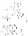
- the DC power system 102 includes energy sources such as alternating current (AC) generators 108, 110 which feed power to a DC bus 120 via power electronic converters 122 and 124 respectively.
- the DC power system 102 may receive energy from a power grid (not shown) via a transmission line (not shown).
- the DC power system 102 also includes an energy storage device 112 which feeds power to a DC bus 126 via a power electronic converter 128.
- the power electronic converters 122, 124 are AC/DC converters as they have to convert power from AC generators to the DC bus whereas power electronic converter 128 is a DC/DC converter as it couples a DC energy storage device to a DC bus.
- the two DC buses 120 and 126 do not have same DC voltage and hence are coupled to each other via a DC/DC converter 130.
- the DC/DC converter 130 may be a bidirectional DC/DC converter or a unidirectional DC/DC converter.
- loads 132 and 134 are connected to DC bus 120 via power electronic converters 136 and 138 respectively, and loads 140 and 142 are connected to the DC bus 122 via power electronic converters 144 and 146 respectively.
- the power electronic converter 136, 138, 144 and 146 may be AC/DC converters or DC/DC converters.
- FIG. 1 is a single line diagram of DC power system 102.
- all converters have been shown to have only one input terminal and one output terminal for ease of explanation.
- a negative terminal or a reference terminal is always there at the input and the output of each of the converter.
- DC bus 120 includes a positive rail and a negative rail (or ground rail) but for ease of explanation only one line is shown.
- the DC power system 102 also includes a controller 147 to control the various AC/DC converters and/or DC/DC converters.
- the DC bus 120 includes two subsections 148 and 149. If there is a short circuit fault on subsection 148 then loads and generators connected to the other subsection 149 will also get affected. Similarly, if there a short circuit fault on subsection 149 then loads and generators connected to the other subsection 148 will get affected. Therefore, in accordance with an embodiment of the present technique, a DC bus separator is presented which isolates a faulty DC bus subsection from a healthy (or non-faulty) DC bus subsection and allows continuity of operation of the healthy DC bus subsection.
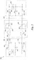
- FIG. 2 illustrates a schematic diagram of a DC bus 200 for use in a DC power system in accordance with aspects of the present disclosure.
- the DC bus 200 includes a positive rail 208, a negative rail 212 and a ground rail 210. Furthermore, the DC bus 200 is split into two subsections 202 and 204. The subsection 202 and 204 are separated by a DC separator 206.
- the DC bus 200 also includes a plurality of capacitors 214 connected between the positive rail 208, the negative rail 212 and the ground rail 210.
- a plurality of loads 236 may be connected to the DC bus 200.
- the loads 236 shown in FIG. 2 are connected between the positive rail 208 and the negative rail 212. But other loads can be connected between the ground rail 210 and the negative rail 212 or between the positive rail 208 and the negative rail 212.
- the DC bus 200 shown in FIG. 2 allows controlled separation of the DC bus subsections 202, 204 when the DC power flow is unidirectional i.e., a DC power transfer from subsection 202 to subsection 204.
- the technique disclosed here is also applicable for a DC bus structure where controlled separation must be provided also with bidirectional power flow, i.e. a DC power transfer between subsection 202 and subsection 204 in both directions.
- the DC bus separator 206 isolates the faulty subsection 204 from the healthy subsection 202. In other words, when the fault occurs, the DC bus separator 206 blocks a DC bus current 230 flowing from the healthy subsection 202 to the faulty subsection 204.
- the DC bus separator 206 includes a positive rail controllable switch 216 in its positive rail 208 and a negative rail controllable switch 218 in its negative rail 212.
- the DC bus separator 206 further includes a positive rail diode-inductor pair 223 in its positive rail 208 and a negative rail diode-inductor pair 225 in its negative rail 212.
- the positive rail diode-inductor pair 223 includes a positive rail diode 220 connected in parallel with a positive rail inductor 222. The positive rail diode-inductor pair 223 is then further connected to the positive rail controllable switch 216.
- the positive rail controllable switch 216 is connected in series with the positive rail inductor 222 and a current path is provided between the subsections 202, 204 during normal operation via the controllable switch 216 and the inductor 222.
- the term 'series connection' refers to a physical and/or electrical connection between two elements i.e., they are connected one after another and one of the terminals of each element is coupled together.
- the positive rail controllable switch 216 is controlled to be switched off to break the current path when a fault is detected on a DC bus subsection.
- the anode of the positive rail diode 220 is coupled to the subsection 204 and the cathode is connected to the controllable switch 216.
- the positive rail diode 220 connected in parallel to the positive rail inductor 222 provides a circulating current path to dissipate an inductor current in the positive rail inductor 222 when the positive rail controllable switch 216 is not conducting or is switched off due to a fault.
- the negative rail diode-inductor pair 225 includes a negative rail diode 224 connected in parallel with a negative rail inductor 226.
- the cathode of the negative rail diode 224 is connected to the negative rail controllable switch 218 and the anode is connected to the subsection 204.
- a current path is provided between the subsections 202, 204 during normal operation via the negative rail controllable switch 218 and the negative rail inductor 226.
- the negative rail controllable switch 218 is controlled to be switched off to break the current path when a fault is detected on a DC bus substation.
- the negative rail diode 224 connected in parallel to the negative rail inductor 226 provides a circulating current path to dissipate an inductor current in the negative rail inductor 226 when the negative rail controllable switch 218 is not conducting or is switched off due to a fault.
- the controllable switches such as switches 216 and 218 may include switching devices based on semiconductor technology, such as an insulated gate bipolar transistor (IGBT), a metal oxide semiconductor field effect transistor (MOSFET), a field effect transistor (FET), a gate turn-off thyristor, an insulated gate commutated thyristor (IGCT), an injection enhanced gate transistor (IEGT), a silicon carbide based switch, a gallium nitride based switch, a gallium arsenide based switch, or equivalents thereof.
- the controllable switches may include a plurality of switching devices connected in series or in parallel or combinations thereof.
- the DC bus 200 allows controlled separation when the DC power flow is unidirectional. Therefore, during normal operation, DC power flows from subsection 202 to subsection 204.
- the controllable switches 216 and 218 are switched on during normal operation and a DC bus current 230 flows in the positive rail 208 from subsection 202 to subsection 204 through the positive rail controllable switch 216 and the positive rail inductor 222.
- the DC bus current 230 in the negative rail 212 flows from subsection 204 to subsection 202 through the negative rail inductor 226 and the negative rail controllable switch 218.
- the diodes 220 and 224 are reverse biased because the DC bus current 230 cannot flow in them when it is positive as indicated in FIG. 2 .
- the DC bus current 230 begins to rise substantially and the inductors 222 and 226 generate increased negative voltage across the diodes 220 and 224. This results in the positive rail diode 220 becoming even more reverse biased.
- the controller 147 switches off the positive rail controllable switch 216 and isolates the positive rail 208 of the healthy (or non-faulty) subsection 202 from the positive rail 208 of the faulty subsection 204.
- the inductor 222 is designed to limit the current rate of increase in the controllable switch 216 so that even after the unavoidable delay caused by sensing and protection, the controllable switch 216 can still be switched off safely i.e., at below its maximum commutable current.
- the current in the inductor 222 starts decreasing which immediately generates forward voltage across the diode 220 and the current then flows through the diode 220 i.e., the diode 220 acts as a freewheeling diode for the inductor current. Since the diode 220 starts conducting, any antiparallel diode across the controllable switch 216 does not conduct.
- the inductor current receives a current path via the diode 220, no significant overvoltage is generated across the controllable switch 216 and also the controllable switch 216 does not need large energy absorbers in parallel to it.
- the inductor current eventually extinguishes and the diode 220 becomes reverse biased again, thereby assuring indefinite separation of the positive rail 208 of the healthy subsection 202 from the faulty subsection 204 and thus, continuity of operation of subsection 202.
- the negative rails 212 of the subsections 202, 204 are still coupled.
- any loads connected between the negative rail 212 and the positive rail 210 of the subsection 204 may still be operative at reduced voltage since the positive rail voltage drops to ground rail voltage because of the short circuit.
- a short circuit fault 234 also occurs on the negative rail 212 of subsection 204, at first the negative rail diode 224 becomes even more reverse biased and then once the negative rail controllable switch 218 is switched off, the negative rail diode 224 becomes forward biased and provides a freewheeling path for the inductor current of the negative rail inductor 226. This separates the negative rails 212 of the subsections 202, 204. Eventually the inductor current extinguishes and the healthy subsection 202 continues to operate normally.
- plot 152 shows four signals, namely a positive rail voltage signal 160 of the faulty subsection 204, a load current signal 162 of the faulty subsection 204, a positive rail voltage signal 164 of the healthy subsection 202, and a load current signal 166 of the healthy subsection 202.
- Plot 154 in FIG. 3 shows two currents signals, namely an inductor current signal 168 of the positive rail inductor 222 and a positive rail current signal 170 of the faulty subsection 204.
- the positive rail current signal 170 reduces to zero at time t1 when the short circuit fault occurs on the positive rail 208 of subsection 204.
- the inductor current signal 168 starts recirculating via positive rail diode 220 and after a while it completely extinguishes.
- Plot 156 in FIG. 3 shows a negative rail voltage signal 172 of the healthy subsection 202 and a negative rail voltage signal 174 of the faulty subsection 204.
- the first fault at time t1 does not affect either of the voltage signals 172 and 174.
- the second short circuit fault which occurs on the negative rail 212 of subsection 204 at time t2 affects the negative rail voltage signal 174 which reduces to zero at time t2.
- plot 158 of FIG. 3 shows an inductor current signal 176 of the negative rail inductor 226 and a negative rail current 178 on the faulty subsection 204. At time t1, the inductor current signal 176 as well as the negative rail current 178 both reduce to half their original value.
- both the inductor current signal 176 and the negative rail current 178 reduce to zero value. It can be noted that as expected the inductor current signal 176 does not reduce to half or zero value immediately at times t1 and t2 respectively, rather it takes a short time before going to zero value. At time t2, the subsections 202, 204 are completely isolated.
- FIG. 4 illustrates a schematic diagram of another DC bus 250 for use in a DC power system in accordance with aspects of the present disclosure.
- the DC bus 250 includes a DC bus subsection 252 and a DC bus subsection 254.
- the DC bus 250 allows bidirectional power flow i.e., the DC power can flow from subsection 252 to subsection 254 or from subsection 254 to subsection 252 as required.
- the DC bus 250 also includes a positive rail 258, a ground rail 260 and a negative rail 262.
- a plurality of capacitors 264 and loads may be connected between the positive rail 258, the ground rail 260 and the negative rail 262. Since the DC bus 250 allows bidirectional power flow, two DC bus separators 266, 268 are used in the embodiment of FIG. 4 .
- the DC power system includes at least two DC bus separators 266, 268, each configured to isolate the healthy subsection from the faulty subsection depending on the direction of the DC bus current.
- a first DC bus separator 266 and a second DC bus separator 268 are connected in series in opposite polarity. It should be noted that two DC bus separators 266, 268 are used in this embodiment as the DC power may flow from subsection 252 to subsection 254 or vice versa . Furthermore, the reason for connecting the two DC bus separators 266, 268 in opposite polarity is that the DC bus current can flow in either direction. Thus, either DC bus separator 266 or DC bus separator 268 may work to protect the system depending on the direction of the DC bus current.
- the first and second DC bus separators 266, 268 include a controllable switch and a diode-inductor pair in its positive and negative rails 258, 262.
- the first DC bus separator 266 includes controllable switches 270 and 272 and diode-inductor pairs 274, 276 in its positive rail 258 and its negative rail 262 respectively.
- the second DC bus separator 268 includes controllable switches 278 and 280 and diode-inductor pairs 282, 284 in its positive rail 258 and its negative rail 262 respectively.
- the DC bus separators 266, 268 operate in a similar manner to the DC bus separator 206 of FIG. 2 .
- the first DC bus separator 266 protects the subsection 252 in case of a fault on the subsection 254 and the second DC bus separator 268 protects the subsection 254 in case of a fault on the subsection 252.
- the anode of the positive rail diode of the first DC bus separator 266 is coupled to the controllable switch 278 of the second DC bus separator 268 and the cathode is connected to the controllable switch 270.
- the cathode of the negative rail diode of the first DC bus separator 266 is connected to the controllable switch 280 of the second DC bus separator and the anode is connected to the controllable switch 272.
- the anode of the positive rail diode of the second DC bus separator 268 is connected to the controllable switch 278 and the cathode is connected to the subsection 254.
- the cathode of the negative rail diode of the second DC bus separate 268 is connected to the controllable switch 280 and the anode is connected to the subsection 254.
- controllable switches 270, 272, 278 and 280 are conducting and the DC current flows through the inductors of the diode-inductor pairs 282 and 284, controllable switches 270, 272, 278, 280, and the diodes of diode-inductor pair 274, 276.
- the diode of the diode-inductor pair 282 becomes even more reverse biased and then once the controllable switch 278 is switched off, the diode of the diode-inductor pair 282 becomes forward biased and provides a freewheeling path for the inductor current of the inductor of the diode-inductor pair 282.
- the inductor current extinguishes and the second DC bus separator 268 isolates the positive rail 258 of the healthy subsection 254 from the positive rail 258 of the faulty subsection 252.
- the first DC bus separator 266 would isolate the positive rail 258 of the healthy subsection 252 from the positive rail 258 of the faulty subsection 254 in a similar manner.
- the first and second DC bus separators 266, 268 will also isolate the negative rail of a healthy subsection from the negative rail of a faulty subsection in a similar manner.
- One of the advantages of the present system is high system availability via a more fault tolerant conversion structure based on splitting of the DC link of power converters.
- the system provides a simple arrangement without varistors for isolation between two subsections of the DC common DC bus.
Landscapes
- Engineering & Computer Science (AREA)
- Power Engineering (AREA)
- Dc-Dc Converters (AREA)
- Direct Current Feeding And Distribution (AREA)
Applications Claiming Priority (1)
| Application Number | Priority Date | Filing Date | Title |
|---|---|---|---|
| US14/609,991 US9853451B2 (en) | 2015-01-30 | 2015-01-30 | Direct current power system |
Publications (2)
| Publication Number | Publication Date |
|---|---|
| EP3051646A1 true EP3051646A1 (fr) | 2016-08-03 |
| EP3051646B1 EP3051646B1 (fr) | 2020-02-26 |
Family
ID=55237512
Family Applications (1)
| Application Number | Title | Priority Date | Filing Date |
|---|---|---|---|
| EP16152390.7A Active EP3051646B1 (fr) | 2015-01-30 | 2016-01-22 | Système d'alimentation en courant continu |
Country Status (5)
| Country | Link |
|---|---|
| US (1) | US9853451B2 (fr) |
| EP (1) | EP3051646B1 (fr) |
| CN (1) | CN105846403B (fr) |
| BR (1) | BR102016000759B1 (fr) |
| CA (1) | CA2918912C (fr) |
Cited By (4)
| Publication number | Priority date | Publication date | Assignee | Title |
|---|---|---|---|---|
| CN110768203A (zh) * | 2019-11-22 | 2020-02-07 | 西北农林科技大学 | 一种基于软开关技术的无弧直流断路器拓扑及其实现方法 |
| WO2020064996A1 (fr) * | 2018-09-28 | 2020-04-02 | Siemens Aktiengesellschaft | Système d'alimentation électrique conçu pour un dispositif maritime comportant différentes zones reliées |
| WO2020193134A1 (fr) * | 2019-03-22 | 2020-10-01 | Siemens Aktiengesellschaft | Commutateur de tension continue |
| EP3799306A1 (fr) * | 2019-09-27 | 2021-03-31 | Siemens Aktiengesellschaft | Commutateur de protection électronique |
Families Citing this family (5)
| Publication number | Priority date | Publication date | Assignee | Title |
|---|---|---|---|---|
| EP3349357A1 (fr) * | 2017-01-13 | 2018-07-18 | Siemens Aktiengesellschaft | Ensemble et procédé de commutation de puissance |
| CN112787315B (zh) * | 2019-11-08 | 2022-03-29 | 株洲中车时代电气股份有限公司 | 一种船舶直流电网纯固态短路保护装置 |
| US11133672B1 (en) | 2020-03-06 | 2021-09-28 | Hamilton Sundstrand Corporation | System and method for adding a high voltage DC source to a power bus |
| CN111834987B (zh) * | 2020-06-05 | 2022-10-11 | 许昌开普检测研究院股份有限公司 | 基于解析故障触发控制字特征值的高压虚拟线路保护方法 |
| CN113114061B (zh) * | 2021-03-26 | 2022-06-24 | 台达电子企业管理(上海)有限公司 | 变换器及抑制变换器的环流干扰的方法 |
Citations (5)
| Publication number | Priority date | Publication date | Assignee | Title |
|---|---|---|---|---|
| US4520279A (en) * | 1983-11-07 | 1985-05-28 | Sundstrand Corporation | Series transistor chopper |
| US4979068A (en) * | 1989-02-07 | 1990-12-18 | Sobhani Seyd M | High speed electronic circuit breaker |
| EP0489945A1 (fr) * | 1990-12-08 | 1992-06-17 | Asea Brown Boveri Ag | Dispositif de commutation pour un GTO-HF |
| WO2011141052A1 (fr) * | 2010-05-11 | 2011-11-17 | Abb Technology Ag | Installation pour transmettre de l'énergie électrique cc à haute tension et comprenant une protection contre les surtensions |
| EP2634885A1 (fr) * | 2012-02-29 | 2013-09-04 | ABB Technology Ltd | Système d'alimentation CC avec capacités de protection de système |
Family Cites Families (13)
| Publication number | Priority date | Publication date | Assignee | Title |
|---|---|---|---|---|
| CA2317995C (fr) | 2000-06-30 | 2011-11-15 | S&C Electric Company | Methodes et dispositifs pouvant detecter des defauts d'isolement, et reagir a ceux-ci, dans des systemes et de l'equipement de distribution d'energie electrique |
| US6624993B1 (en) * | 2000-11-22 | 2003-09-23 | The Regents Of The University Of California | Adjustable direct current and pulsed circuit fault current limiter |
| US20030071633A1 (en) | 2001-10-16 | 2003-04-17 | Fedirchuk David James | Bus fault protection unit for an electrical power system |
| CN103004048B (zh) | 2010-06-14 | 2015-04-15 | Abb研究有限公司 | Hvdc输电线路的故障保护 |
| WO2012038100A1 (fr) | 2010-09-24 | 2012-03-29 | Siemens Aktiengesellschaft | Système sous-marin de transmission du courant continu |
| US8743514B2 (en) | 2011-04-25 | 2014-06-03 | General Electric Company | HVDC power transmission with cable fault ride-through capability |
| DE102011083514A1 (de) | 2011-09-27 | 2013-03-28 | Siemens Aktiengesellschaft | Gleichspannungs-Leistungsschalter |
| DE102011083693B3 (de) | 2011-09-29 | 2013-03-28 | Siemens Aktiengesellschaft | Gleichspannungs-Leitungsschutzschalter |
| EP2820435B1 (fr) | 2012-02-28 | 2016-04-20 | ABB Technology Ltd. | Procédé et appareil pour détecter un défaut dans un système de transmission d'énergie hvdc |
| WO2013152799A1 (fr) | 2012-04-13 | 2013-10-17 | Abb Technology Ag | Disjoncteur à courant continu à résistance passive |
| US9007735B2 (en) | 2012-04-27 | 2015-04-14 | The Regents Of The University Of Colorado, A Body Corporate | Fault detection, isolation, location and reconnection systems and methods |
| EP2750257B1 (fr) | 2012-09-17 | 2016-05-11 | GE Energy Power Conversion Technology Ltd | Disjoncteurs |
| US9618586B2 (en) | 2013-02-12 | 2017-04-11 | Abb Schweiz Ag | Method and device for detection of a fault in a protected unit |
-
2015
- 2015-01-30 US US14/609,991 patent/US9853451B2/en active Active
-
2016
- 2016-01-14 BR BR102016000759-3A patent/BR102016000759B1/pt active IP Right Grant
- 2016-01-21 CA CA2918912A patent/CA2918912C/fr active Active
- 2016-01-22 EP EP16152390.7A patent/EP3051646B1/fr active Active
- 2016-01-29 CN CN201610062208.5A patent/CN105846403B/zh not_active Expired - Fee Related
Patent Citations (5)
| Publication number | Priority date | Publication date | Assignee | Title |
|---|---|---|---|---|
| US4520279A (en) * | 1983-11-07 | 1985-05-28 | Sundstrand Corporation | Series transistor chopper |
| US4979068A (en) * | 1989-02-07 | 1990-12-18 | Sobhani Seyd M | High speed electronic circuit breaker |
| EP0489945A1 (fr) * | 1990-12-08 | 1992-06-17 | Asea Brown Boveri Ag | Dispositif de commutation pour un GTO-HF |
| WO2011141052A1 (fr) * | 2010-05-11 | 2011-11-17 | Abb Technology Ag | Installation pour transmettre de l'énergie électrique cc à haute tension et comprenant une protection contre les surtensions |
| EP2634885A1 (fr) * | 2012-02-29 | 2013-09-04 | ABB Technology Ltd | Système d'alimentation CC avec capacités de protection de système |
Cited By (8)
| Publication number | Priority date | Publication date | Assignee | Title |
|---|---|---|---|---|
| WO2020064996A1 (fr) * | 2018-09-28 | 2020-04-02 | Siemens Aktiengesellschaft | Système d'alimentation électrique conçu pour un dispositif maritime comportant différentes zones reliées |
| CN113169550A (zh) * | 2018-09-28 | 2021-07-23 | 西门子能源全球有限两合公司 | 用于具有不同连接区的涉水装置的供能系统 |
| CN113169550B (zh) * | 2018-09-28 | 2024-02-20 | 西门子能源全球有限两合公司 | 用于具有不同连接区的涉水装置的供能系统 |
| WO2020193134A1 (fr) * | 2019-03-22 | 2020-10-01 | Siemens Aktiengesellschaft | Commutateur de tension continue |
| EP3799306A1 (fr) * | 2019-09-27 | 2021-03-31 | Siemens Aktiengesellschaft | Commutateur de protection électronique |
| WO2021058197A1 (fr) * | 2019-09-27 | 2021-04-01 | Siemens Aktiengesellschaft | Disjoncteur électronique |
| CN110768203A (zh) * | 2019-11-22 | 2020-02-07 | 西北农林科技大学 | 一种基于软开关技术的无弧直流断路器拓扑及其实现方法 |
| CN110768203B (zh) * | 2019-11-22 | 2024-04-26 | 西北农林科技大学 | 一种基于软开关技术的无弧直流断路器拓扑及其实现方法 |
Also Published As
| Publication number | Publication date |
|---|---|
| CA2918912C (fr) | 2024-02-20 |
| CN105846403B (zh) | 2019-12-24 |
| BR102016000759B1 (pt) | 2022-08-16 |
| BR102016000759A2 (pt) | 2016-08-23 |
| US20160226251A1 (en) | 2016-08-04 |
| CN105846403A (zh) | 2016-08-10 |
| EP3051646B1 (fr) | 2020-02-26 |
| CA2918912A1 (fr) | 2016-07-30 |
| US9853451B2 (en) | 2017-12-26 |
Similar Documents
| Publication | Publication Date | Title |
|---|---|---|
| EP3051646B1 (fr) | Système d'alimentation en courant continu | |
| AU2018203019B2 (en) | Direct-current transmission protection apparatus, current converter, and protection method | |
| US8687389B2 (en) | Apparatus having a converter | |
| EP2980944B1 (fr) | Système d'alimentation en courant continu pour des applications maritimes | |
| US9745038B2 (en) | DC power system for marine applications | |
| US9780643B2 (en) | DC power system for marine applications | |
| US11316443B2 (en) | Control of active neutral-point clamped three-level converter | |
| US10230260B2 (en) | Fast utility disconnect switch for single conversion UPS | |
| KR102266020B1 (ko) | 전력 변환 장치 | |
| US20160006368A1 (en) | Power Converter | |
| US10862300B2 (en) | Power distribution system | |
| EP3048689B1 (fr) | Système d'alimentation en courant continu | |
| CN108616223B (zh) | 一种基于igct的模块化多电平换流器及故障处理方法 | |
| EP2980945B1 (fr) | Système d'alimentation en courant continu pour des applications maritimes | |
| CN105896477A (zh) | 一种模块化多电平换流器的接地保护方法及模块化多电平换流器 | |
| CN109672329B (zh) | 一种模块化系统的保护电路 | |
| CN207896655U (zh) | 一种电压源换流器保护电路 |
Legal Events
| Date | Code | Title | Description |
|---|---|---|---|
| PUAI | Public reference made under article 153(3) epc to a published international application that has entered the european phase |
Free format text: ORIGINAL CODE: 0009012 |
|
| AK | Designated contracting states |
Kind code of ref document: A1 Designated state(s): AL AT BE BG CH CY CZ DE DK EE ES FI FR GB GR HR HU IE IS IT LI LT LU LV MC MK MT NL NO PL PT RO RS SE SI SK SM TR |
|
| AX | Request for extension of the european patent |
Extension state: BA ME |
|
| STAA | Information on the status of an ep patent application or granted ep patent |
Free format text: STATUS: REQUEST FOR EXAMINATION WAS MADE |
|
| 17P | Request for examination filed |
Effective date: 20170131 |
|
| RBV | Designated contracting states (corrected) |
Designated state(s): AL AT BE BG CH CY CZ DE DK EE ES FI FR GB GR HR HU IE IS IT LI LT LU LV MC MK MT NL NO PL PT RO RS SE SI SK SM TR |
|
| GRAP | Despatch of communication of intention to grant a patent |
Free format text: ORIGINAL CODE: EPIDOSNIGR1 |
|
| STAA | Information on the status of an ep patent application or granted ep patent |
Free format text: STATUS: GRANT OF PATENT IS INTENDED |
|
| RIC1 | Information provided on ipc code assigned before grant |
Ipc: H02H 7/26 20060101AFI20190821BHEP Ipc: H03K 17/66 20060101ALI20190821BHEP Ipc: H03K 17/08 20060101ALI20190821BHEP Ipc: H02J 1/10 20060101ALI20190821BHEP Ipc: H02J 3/38 20060101ALI20190821BHEP Ipc: H01H 33/59 20060101ALI20190821BHEP Ipc: H02H 3/20 20060101ALN20190821BHEP Ipc: H02H 3/087 20060101ALN20190821BHEP |
|
| INTG | Intention to grant announced |
Effective date: 20190912 |
|
| GRAS | Grant fee paid |
Free format text: ORIGINAL CODE: EPIDOSNIGR3 |
|
| GRAA | (expected) grant |
Free format text: ORIGINAL CODE: 0009210 |
|
| STAA | Information on the status of an ep patent application or granted ep patent |
Free format text: STATUS: THE PATENT HAS BEEN GRANTED |
|
| AK | Designated contracting states |
Kind code of ref document: B1 Designated state(s): AL AT BE BG CH CY CZ DE DK EE ES FI FR GB GR HR HU IE IS IT LI LT LU LV MC MK MT NL NO PL PT RO RS SE SI SK SM TR |
|
| REG | Reference to a national code |
Ref country code: GB Ref legal event code: FG4D |
|
| REG | Reference to a national code |
Ref country code: CH Ref legal event code: EP |
|
| REG | Reference to a national code |
Ref country code: AT Ref legal event code: REF Ref document number: 1238815 Country of ref document: AT Kind code of ref document: T Effective date: 20200315 |
|
| REG | Reference to a national code |
Ref country code: IE Ref legal event code: FG4D |
|
| REG | Reference to a national code |
Ref country code: DE Ref legal event code: R096 Ref document number: 602016030388 Country of ref document: DE |
|
| PG25 | Lapsed in a contracting state [announced via postgrant information from national office to epo] |
Ref country code: NO Free format text: LAPSE BECAUSE OF FAILURE TO SUBMIT A TRANSLATION OF THE DESCRIPTION OR TO PAY THE FEE WITHIN THE PRESCRIBED TIME-LIMIT Effective date: 20200526 Ref country code: FI Free format text: LAPSE BECAUSE OF FAILURE TO SUBMIT A TRANSLATION OF THE DESCRIPTION OR TO PAY THE FEE WITHIN THE PRESCRIBED TIME-LIMIT Effective date: 20200226 Ref country code: RS Free format text: LAPSE BECAUSE OF FAILURE TO SUBMIT A TRANSLATION OF THE DESCRIPTION OR TO PAY THE FEE WITHIN THE PRESCRIBED TIME-LIMIT Effective date: 20200226 |
|
| REG | Reference to a national code |
Ref country code: NL Ref legal event code: MP Effective date: 20200226 |
|
| REG | Reference to a national code |
Ref country code: LT Ref legal event code: MG4D |
|
| PG25 | Lapsed in a contracting state [announced via postgrant information from national office to epo] |
Ref country code: IS Free format text: LAPSE BECAUSE OF FAILURE TO SUBMIT A TRANSLATION OF THE DESCRIPTION OR TO PAY THE FEE WITHIN THE PRESCRIBED TIME-LIMIT Effective date: 20200626 Ref country code: BG Free format text: LAPSE BECAUSE OF FAILURE TO SUBMIT A TRANSLATION OF THE DESCRIPTION OR TO PAY THE FEE WITHIN THE PRESCRIBED TIME-LIMIT Effective date: 20200526 Ref country code: GR Free format text: LAPSE BECAUSE OF FAILURE TO SUBMIT A TRANSLATION OF THE DESCRIPTION OR TO PAY THE FEE WITHIN THE PRESCRIBED TIME-LIMIT Effective date: 20200527 Ref country code: HR Free format text: LAPSE BECAUSE OF FAILURE TO SUBMIT A TRANSLATION OF THE DESCRIPTION OR TO PAY THE FEE WITHIN THE PRESCRIBED TIME-LIMIT Effective date: 20200226 Ref country code: LV Free format text: LAPSE BECAUSE OF FAILURE TO SUBMIT A TRANSLATION OF THE DESCRIPTION OR TO PAY THE FEE WITHIN THE PRESCRIBED TIME-LIMIT Effective date: 20200226 Ref country code: SE Free format text: LAPSE BECAUSE OF FAILURE TO SUBMIT A TRANSLATION OF THE DESCRIPTION OR TO PAY THE FEE WITHIN THE PRESCRIBED TIME-LIMIT Effective date: 20200226 |
|
| PG25 | Lapsed in a contracting state [announced via postgrant information from national office to epo] |
Ref country code: NL Free format text: LAPSE BECAUSE OF FAILURE TO SUBMIT A TRANSLATION OF THE DESCRIPTION OR TO PAY THE FEE WITHIN THE PRESCRIBED TIME-LIMIT Effective date: 20200226 |
|
| PG25 | Lapsed in a contracting state [announced via postgrant information from national office to epo] |
Ref country code: EE Free format text: LAPSE BECAUSE OF FAILURE TO SUBMIT A TRANSLATION OF THE DESCRIPTION OR TO PAY THE FEE WITHIN THE PRESCRIBED TIME-LIMIT Effective date: 20200226 Ref country code: SM Free format text: LAPSE BECAUSE OF FAILURE TO SUBMIT A TRANSLATION OF THE DESCRIPTION OR TO PAY THE FEE WITHIN THE PRESCRIBED TIME-LIMIT Effective date: 20200226 Ref country code: LT Free format text: LAPSE BECAUSE OF FAILURE TO SUBMIT A TRANSLATION OF THE DESCRIPTION OR TO PAY THE FEE WITHIN THE PRESCRIBED TIME-LIMIT Effective date: 20200226 Ref country code: ES Free format text: LAPSE BECAUSE OF FAILURE TO SUBMIT A TRANSLATION OF THE DESCRIPTION OR TO PAY THE FEE WITHIN THE PRESCRIBED TIME-LIMIT Effective date: 20200226 Ref country code: DK Free format text: LAPSE BECAUSE OF FAILURE TO SUBMIT A TRANSLATION OF THE DESCRIPTION OR TO PAY THE FEE WITHIN THE PRESCRIBED TIME-LIMIT Effective date: 20200226 Ref country code: PT Free format text: LAPSE BECAUSE OF FAILURE TO SUBMIT A TRANSLATION OF THE DESCRIPTION OR TO PAY THE FEE WITHIN THE PRESCRIBED TIME-LIMIT Effective date: 20200719 Ref country code: CZ Free format text: LAPSE BECAUSE OF FAILURE TO SUBMIT A TRANSLATION OF THE DESCRIPTION OR TO PAY THE FEE WITHIN THE PRESCRIBED TIME-LIMIT Effective date: 20200226 Ref country code: SK Free format text: LAPSE BECAUSE OF FAILURE TO SUBMIT A TRANSLATION OF THE DESCRIPTION OR TO PAY THE FEE WITHIN THE PRESCRIBED TIME-LIMIT Effective date: 20200226 Ref country code: RO Free format text: LAPSE BECAUSE OF FAILURE TO SUBMIT A TRANSLATION OF THE DESCRIPTION OR TO PAY THE FEE WITHIN THE PRESCRIBED TIME-LIMIT Effective date: 20200226 |
|
| REG | Reference to a national code |
Ref country code: AT Ref legal event code: MK05 Ref document number: 1238815 Country of ref document: AT Kind code of ref document: T Effective date: 20200226 |
|
| REG | Reference to a national code |
Ref country code: DE Ref legal event code: R097 Ref document number: 602016030388 Country of ref document: DE |
|
| PLBE | No opposition filed within time limit |
Free format text: ORIGINAL CODE: 0009261 |
|
| STAA | Information on the status of an ep patent application or granted ep patent |
Free format text: STATUS: NO OPPOSITION FILED WITHIN TIME LIMIT |
|
| PG25 | Lapsed in a contracting state [announced via postgrant information from national office to epo] |
Ref country code: IT Free format text: LAPSE BECAUSE OF FAILURE TO SUBMIT A TRANSLATION OF THE DESCRIPTION OR TO PAY THE FEE WITHIN THE PRESCRIBED TIME-LIMIT Effective date: 20200226 Ref country code: AT Free format text: LAPSE BECAUSE OF FAILURE TO SUBMIT A TRANSLATION OF THE DESCRIPTION OR TO PAY THE FEE WITHIN THE PRESCRIBED TIME-LIMIT Effective date: 20200226 |
|
| 26N | No opposition filed |
Effective date: 20201127 |
|
| PG25 | Lapsed in a contracting state [announced via postgrant information from national office to epo] |
Ref country code: SI Free format text: LAPSE BECAUSE OF FAILURE TO SUBMIT A TRANSLATION OF THE DESCRIPTION OR TO PAY THE FEE WITHIN THE PRESCRIBED TIME-LIMIT Effective date: 20200226 Ref country code: PL Free format text: LAPSE BECAUSE OF FAILURE TO SUBMIT A TRANSLATION OF THE DESCRIPTION OR TO PAY THE FEE WITHIN THE PRESCRIBED TIME-LIMIT Effective date: 20200226 |
|
| PG25 | Lapsed in a contracting state [announced via postgrant information from national office to epo] |
Ref country code: MC Free format text: LAPSE BECAUSE OF FAILURE TO SUBMIT A TRANSLATION OF THE DESCRIPTION OR TO PAY THE FEE WITHIN THE PRESCRIBED TIME-LIMIT Effective date: 20200226 |
|
| REG | Reference to a national code |
Ref country code: CH Ref legal event code: PL |
|
| PG25 | Lapsed in a contracting state [announced via postgrant information from national office to epo] |
Ref country code: LU Free format text: LAPSE BECAUSE OF NON-PAYMENT OF DUE FEES Effective date: 20210122 |
|
| REG | Reference to a national code |
Ref country code: BE Ref legal event code: MM Effective date: 20210131 |
|
| PG25 | Lapsed in a contracting state [announced via postgrant information from national office to epo] |
Ref country code: LI Free format text: LAPSE BECAUSE OF NON-PAYMENT OF DUE FEES Effective date: 20210131 Ref country code: CH Free format text: LAPSE BECAUSE OF NON-PAYMENT OF DUE FEES Effective date: 20210131 |
|
| PG25 | Lapsed in a contracting state [announced via postgrant information from national office to epo] |
Ref country code: IE Free format text: LAPSE BECAUSE OF NON-PAYMENT OF DUE FEES Effective date: 20210122 |
|
| PG25 | Lapsed in a contracting state [announced via postgrant information from national office to epo] |
Ref country code: BE Free format text: LAPSE BECAUSE OF NON-PAYMENT OF DUE FEES Effective date: 20210131 |
|
| PG25 | Lapsed in a contracting state [announced via postgrant information from national office to epo] |
Ref country code: HU Free format text: LAPSE BECAUSE OF FAILURE TO SUBMIT A TRANSLATION OF THE DESCRIPTION OR TO PAY THE FEE WITHIN THE PRESCRIBED TIME-LIMIT; INVALID AB INITIO Effective date: 20160122 |
|
| PG25 | Lapsed in a contracting state [announced via postgrant information from national office to epo] |
Ref country code: CY Free format text: LAPSE BECAUSE OF FAILURE TO SUBMIT A TRANSLATION OF THE DESCRIPTION OR TO PAY THE FEE WITHIN THE PRESCRIBED TIME-LIMIT Effective date: 20200226 |
|
| REG | Reference to a national code |
Ref country code: GB Ref legal event code: 732E Free format text: REGISTERED BETWEEN 20231207 AND 20231213 |
|
| PGFP | Annual fee paid to national office [announced via postgrant information from national office to epo] |
Ref country code: GB Payment date: 20231219 Year of fee payment: 9 |
|
| PGFP | Annual fee paid to national office [announced via postgrant information from national office to epo] |
Ref country code: FR Payment date: 20231219 Year of fee payment: 9 |
|
| PG25 | Lapsed in a contracting state [announced via postgrant information from national office to epo] |
Ref country code: MK Free format text: LAPSE BECAUSE OF FAILURE TO SUBMIT A TRANSLATION OF THE DESCRIPTION OR TO PAY THE FEE WITHIN THE PRESCRIBED TIME-LIMIT Effective date: 20200226 |
|
| PGFP | Annual fee paid to national office [announced via postgrant information from national office to epo] |
Ref country code: DE Payment date: 20231219 Year of fee payment: 9 |