EP3051611B1 - Battery cell comprising means for protecting short circuit - Google Patents
Battery cell comprising means for protecting short circuit Download PDFInfo
- Publication number
- EP3051611B1 EP3051611B1 EP14866202.6A EP14866202A EP3051611B1 EP 3051611 B1 EP3051611 B1 EP 3051611B1 EP 14866202 A EP14866202 A EP 14866202A EP 3051611 B1 EP3051611 B1 EP 3051611B1
- Authority
- EP
- European Patent Office
- Prior art keywords
- battery cell
- electrode assembly
- rubber
- battery
- insulative material
- Prior art date
- Legal status (The legal status is an assumption and is not a legal conclusion. Google has not performed a legal analysis and makes no representation as to the accuracy of the status listed.)
- Active
Links
Images
Classifications
-
- H—ELECTRICITY
- H01—ELECTRIC ELEMENTS
- H01M—PROCESSES OR MEANS, e.g. BATTERIES, FOR THE DIRECT CONVERSION OF CHEMICAL ENERGY INTO ELECTRICAL ENERGY
- H01M10/00—Secondary cells; Manufacture thereof
- H01M10/05—Accumulators with non-aqueous electrolyte
- H01M10/058—Construction or manufacture
- H01M10/0587—Construction or manufacture of accumulators having only wound construction elements, i.e. wound positive electrodes, wound negative electrodes and wound separators
-
- H—ELECTRICITY
- H01—ELECTRIC ELEMENTS
- H01M—PROCESSES OR MEANS, e.g. BATTERIES, FOR THE DIRECT CONVERSION OF CHEMICAL ENERGY INTO ELECTRICAL ENERGY
- H01M50/00—Constructional details or processes of manufacture of the non-active parts of electrochemical cells other than fuel cells, e.g. hybrid cells
- H01M50/10—Primary casings; Jackets or wrappings
- H01M50/102—Primary casings; Jackets or wrappings characterised by their shape or physical structure
- H01M50/105—Pouches or flexible bags
-
- H—ELECTRICITY
- H01—ELECTRIC ELEMENTS
- H01M—PROCESSES OR MEANS, e.g. BATTERIES, FOR THE DIRECT CONVERSION OF CHEMICAL ENERGY INTO ELECTRICAL ENERGY
- H01M50/00—Constructional details or processes of manufacture of the non-active parts of electrochemical cells other than fuel cells, e.g. hybrid cells
- H01M50/10—Primary casings; Jackets or wrappings
- H01M50/116—Primary casings; Jackets or wrappings characterised by the material
- H01M50/124—Primary casings; Jackets or wrappings characterised by the material having a layered structure
-
- H—ELECTRICITY
- H01—ELECTRIC ELEMENTS
- H01M—PROCESSES OR MEANS, e.g. BATTERIES, FOR THE DIRECT CONVERSION OF CHEMICAL ENERGY INTO ELECTRICAL ENERGY
- H01M50/00—Constructional details or processes of manufacture of the non-active parts of electrochemical cells other than fuel cells, e.g. hybrid cells
- H01M50/10—Primary casings; Jackets or wrappings
- H01M50/147—Lids or covers
-
- H—ELECTRICITY
- H01—ELECTRIC ELEMENTS
- H01M—PROCESSES OR MEANS, e.g. BATTERIES, FOR THE DIRECT CONVERSION OF CHEMICAL ENERGY INTO ELECTRICAL ENERGY
- H01M50/00—Constructional details or processes of manufacture of the non-active parts of electrochemical cells other than fuel cells, e.g. hybrid cells
- H01M50/50—Current conducting connections for cells or batteries
- H01M50/543—Terminals
- H01M50/547—Terminals characterised by the disposition of the terminals on the cells
-
- H—ELECTRICITY
- H01—ELECTRIC ELEMENTS
- H01M—PROCESSES OR MEANS, e.g. BATTERIES, FOR THE DIRECT CONVERSION OF CHEMICAL ENERGY INTO ELECTRICAL ENERGY
- H01M50/00—Constructional details or processes of manufacture of the non-active parts of electrochemical cells other than fuel cells, e.g. hybrid cells
- H01M50/50—Current conducting connections for cells or batteries
- H01M50/572—Means for preventing undesired use or discharge
- H01M50/584—Means for preventing undesired use or discharge for preventing incorrect connections inside or outside the batteries
- H01M50/586—Means for preventing undesired use or discharge for preventing incorrect connections inside or outside the batteries inside the batteries, e.g. incorrect connections of electrodes
-
- H—ELECTRICITY
- H01—ELECTRIC ELEMENTS
- H01M—PROCESSES OR MEANS, e.g. BATTERIES, FOR THE DIRECT CONVERSION OF CHEMICAL ENERGY INTO ELECTRICAL ENERGY
- H01M10/00—Secondary cells; Manufacture thereof
- H01M10/05—Accumulators with non-aqueous electrolyte
- H01M10/052—Li-accumulators
-
- H—ELECTRICITY
- H01—ELECTRIC ELEMENTS
- H01M—PROCESSES OR MEANS, e.g. BATTERIES, FOR THE DIRECT CONVERSION OF CHEMICAL ENERGY INTO ELECTRICAL ENERGY
- H01M10/00—Secondary cells; Manufacture thereof
- H01M10/05—Accumulators with non-aqueous electrolyte
- H01M10/052—Li-accumulators
- H01M10/0525—Rocking-chair batteries, i.e. batteries with lithium insertion or intercalation in both electrodes; Lithium-ion batteries
-
- H—ELECTRICITY
- H01—ELECTRIC ELEMENTS
- H01M—PROCESSES OR MEANS, e.g. BATTERIES, FOR THE DIRECT CONVERSION OF CHEMICAL ENERGY INTO ELECTRICAL ENERGY
- H01M2200/00—Safety devices for primary or secondary batteries
-
- Y—GENERAL TAGGING OF NEW TECHNOLOGICAL DEVELOPMENTS; GENERAL TAGGING OF CROSS-SECTIONAL TECHNOLOGIES SPANNING OVER SEVERAL SECTIONS OF THE IPC; TECHNICAL SUBJECTS COVERED BY FORMER USPC CROSS-REFERENCE ART COLLECTIONS [XRACs] AND DIGESTS
- Y02—TECHNOLOGIES OR APPLICATIONS FOR MITIGATION OR ADAPTATION AGAINST CLIMATE CHANGE
- Y02E—REDUCTION OF GREENHOUSE GAS [GHG] EMISSIONS, RELATED TO ENERGY GENERATION, TRANSMISSION OR DISTRIBUTION
- Y02E60/00—Enabling technologies; Technologies with a potential or indirect contribution to GHG emissions mitigation
- Y02E60/10—Energy storage using batteries
-
- Y—GENERAL TAGGING OF NEW TECHNOLOGICAL DEVELOPMENTS; GENERAL TAGGING OF CROSS-SECTIONAL TECHNOLOGIES SPANNING OVER SEVERAL SECTIONS OF THE IPC; TECHNICAL SUBJECTS COVERED BY FORMER USPC CROSS-REFERENCE ART COLLECTIONS [XRACs] AND DIGESTS
- Y02—TECHNOLOGIES OR APPLICATIONS FOR MITIGATION OR ADAPTATION AGAINST CLIMATE CHANGE
- Y02P—CLIMATE CHANGE MITIGATION TECHNOLOGIES IN THE PRODUCTION OR PROCESSING OF GOODS
- Y02P70/00—Climate change mitigation technologies in the production process for final industrial or consumer products
- Y02P70/50—Manufacturing or production processes characterised by the final manufactured product
Definitions
- the present invention relates to a battery cell having a means for preventing short-circuit.
- secondary batteries may be classified based on the shape of a battery case of each of the secondary batteries into a cylindrical battery configured to have a structure in which an electrode assembly is mounted in a cylindrical metal container, a prismatic battery configured to have a structure in which an electrode assembly is mounted in a prismatic metal container, and a pouch-shaped battery configured to have a structure in which an electrode assembly is mounted in a pouch-shaped case made of a laminated aluminum sheet.
- a pouch-shaped battery configured to have a structure in which such a stacked or stacked/folded type electrode assembly is mounted in a pouch-shaped battery case made of a laminated aluminum sheet because of low manufacturing costs, light weight, easy modification of the shape thereof, etc.
- the use of such a pouch-shaped battery has gradually increased.
- secondary batteries may be classified based on the structure of an electrode assembly, which has a structure in which a positive electrode and a negative electrode are stacked in a state in which a separator is interposed between the positive electrode and the negative electrode.
- the electrode assembly may be configured to have a jelly-roll (wound) type structure in which a long sheet type positive electrode and a long sheet type negative electrode are wound in a state in which a separator is disposed between the positive electrode and the negative electrode or a stacked type structure in which pluralities of positive electrodes and negative electrodes each having a predetermined size are sequentially stacked in a state in which separators are disposed respectively between the positive electrodes and the negative electrodes.
- a stacked/folded type electrode assembly which is a combination of the jelly roll type electrode assembly and the stacked type electrode assembly, having an improved structure in which predetermined numbers of positive electrodes and negative electrodes are sequentially stacked in a state in which separators are disposed respectively between the positive electrodes and the negative electrodes to constitute a bi-cell or a full cell, after which a plurality of bi-cells or full cells is sequentially folded while being placed on a separation film.
- a secondary battery may explode due to high temperature and pressure in the secondary battery which may be caused by an abnormal state of the secondary battery, such as internal short-circuit of the secondary battery, overcharge of the secondary battery with higher than allowed current or voltage, exposure of the secondary battery to high temperature, or deformation of the secondary battery due to drop of the secondary battery or external impact applied to the secondary battery.
- an abnormal state of the secondary battery such as internal short-circuit of the secondary battery, overcharge of the secondary battery with higher than allowed current or voltage, exposure of the secondary battery to high temperature, or deformation of the secondary battery due to drop of the secondary battery or external impact applied to the secondary battery.
- the metal member directly contacts electrodes of an electrode assembly, with the result that an internal short-circuit may occur in the battery cell or the battery cell may catch fire, thereby greatly reducing the safety of the battery cell.
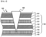
- FIG. 1 is a typical view schematically showing an example in which a conventional battery cell is locally damaged by a metal member.
- a battery cell 100 is configured to have a structure in which an electrode assembly 150, including positive electrodes 111 and 112 and negative electrodes 121 and 122 in a state in which separators 131, 132, and 133 are interposed respectively between the positive electrodes 111 and 112 and the negative electrodes 121 and 122, is mounted in battery cases 141 and 142. A portion of the battery cell 100 is damaged by a metal member 160, which has penetrated into the battery cell 100 from outside the battery cell 100.
- the metal member 160 has broken through the battery case 141 and then penetrated into the battery cell 100, with the result that the electrode assembly 150 has been locally damaged.
- the positive electrodes 111 and 112 and the negative electrodes 121 and 122, which constitute the electrode assembly 150 directly contact the metal member 160.
- an internal short-circuit occurs in the battery cell 100, with the result that the battery cell may catch fire or explode.
- US 2013/196215 A1 is concerned with outer casing material for a battery and a lithium secondary battery.
- the present invention has been made to solve the above problems and other technical problems that have yet to be resolved. It is an object of the present invention to provide a battery cell having an insulative material provided between an electrode assembly and a battery case for preventing the occurrence of a short-circuit in the battery cell or combustion of the battery cell due to direct contact between electrodes of the electrode assembly and a metal member penetrating into the battery cell when the battery cell is damaged by the metal member, thereby improving the safety of the battery cell.
- the above and other objects can be accomplished by the provision of a battery cell as defined in claim 1.
- the insulative material is provided between the electrode assembly and the battery case. Consequently, it is possible to prevent the occurrence of a short-circuit in the battery cell or combustion of the battery cell due to direct contact between the electrodes of the electrode assembly and the metal member penetrating into the battery cell when the battery cell is damaged by the metal member, thereby improving the safety of the battery cell.
- the insulative material is provided at the outer surface of a conventional electrode assembly or the inner surface of a conventional battery case regardless of the shape of the electrode assembly. Consequently, it is possible to improve the safety of the battery cell using a simple structure.
- the insulative material may be provided between the electrode assembly and the battery case in a state in which the insulative material is in tight contact with the outer surface of the electrode assembly or the inner surface of the battery case.
- the insulative material is provided in the electrode assembly, e.g. between the positive electrode and the negative electrode, the flow of ions between the electrodes may be disturbed by the insulative material. If the insulative material is provided at the outer surface of the battery case, on the other hand, the insulative material is exposed outward. In this case, the insulative material may be weakened by contaminants, may be deteriorated, or may be worn. As a result, the battery case may be partially or entirely exposed outward, and therefore the insulative material may not exhibit desired effects.
- the insulative material is provided between the electrode assembly and the battery case in a state in which the insulative material is in tight contact with the outer surface of the electrode assembly, which faces the inner surface of the battery case, or the inner surface of the battery case, which faces the outer surface of the electrode assembly.
- the insulative material is located between the metal member and the electrodes of the electrode assembly when the battery cell is damaged by the metal member. Consequently, it is possible to prevent direct contact between the metal member and the electrodes of the electrode assembly, thereby preventing the battery cell from catching fire or exploding, thus improving the safety of the battery cell
- the insulative material may be provided on both the outer surface of the electrode assembly and the inner surface of the battery case.
- the insulative material is entirely or partially provided at the remaining region of the electrode assembly, excluding the positive electrode terminal and the negative electrode terminal of the electrode assembly, between the electrode assembly and the battery case.
- the insulative material may be locally provided only at a region of the electrode assembly that is exposed outward and may thus be easily broken, or may be entirely provided at the remaining region of the electrode assembly excluding the positive electrode terminal and the negative electrode terminal of the electrode assembly, depending on the shape of a device to which the battery cell is applied.
- the insulative material may be provided over 30 to 90%, preferably 50 to 70%, of the entire area of the outer surface of the electrode assembly or the inner surface of the battery case.
- the insulative material has a thickness equivalent to 0.1 to 20%, preferably 5 to 10%, of the thickness of the electrode assembly.
- the insulative material is provided over less than 30% of the entire area of the outer surface of the electrode assembly or the inner surface of the battery case or if the insulative material has a thickness equivalent to less than 0.1% of the thickness of the electrode assembly, it is not possible to exhibit a desired short-circuit prevention effect.
- the insulative material is provided at more than 90% of the entire area of the outer surface of the electrode assembly or the inner surface of the battery case or if the insulative material has a thickness equivalent to more than 20% of the thickness of the electrode assembly, it may be difficult to impregnate the electrode assembly with an electrolyte.
- the insulative material is elastically stretched into a shape surrounding the outer surface of the metal member, which has penetrated into the electrode assembly.
- the insulative material is provided over less than 30% of the entire area of the outer surface of the electrode assembly or the inner surface of the battery case, therefore, it is not possible to effectively prevent direct contact between the metal member and the positive and negative electrodes of the electrode assembly to thus exhibit a desired safety improvement effect, since the insulative material does not cover the entirety of the outer surface of the metal member, which has penetrated into the electrode assembly.
- the insulative material has a thickness equivalent to less than 0.1% of the thickness of the electrode assembly, the insulative material may be damaged depending on the shape or rigidity of the metal member, whereby it is not possible to exhibit a desired safety improvement effect.
- the insulative material is not particularly restricted so long as the insulative material is provided at the outer surface of the electrode assembly or the inner surface of the battery case in order to exhibit a desired short-circuit prevention effect and a desired safety improvement effect while not affecting the performance of the battery cell.
- the insulative material may be insulative paint, Parafilm, foamed rubber, or a mixture thereof.
- the insulative paint may be at least one selected from a group consisting of acrylonitrile-butadiene rubber (NBR), styrene butadiene rubber (SBR), isobutylene isoprene rubber (IRR), chloroprene rubber (CR), and ethylene propylene diene monomer (EPDM).
- NBR acrylonitrile-butadiene rubber
- SBR styrene butadiene rubber
- IRR isobutylene isoprene rubber
- CR chloroprene rubber
- EPDM ethylene propylene diene monomer
- the foamed rubber may be natural rubber or synthetic rubber.
- the synthetic rubber may be at least one selected from a group consisting of styrene butadiene rubber, polychloroprene rubber, nitrile rubber, butyl rubber, butadiene rubber, isoprene rubber, ethylene propylene rubber, polysulfide rubber, silicone rubber, fluoro rubber, urethane rubber, and acrylic rubber.
- the structure of the electrode assembly constituting the battery cell according to the present invention is not particularly restricted so long as the electrode assembly is configured to have a structure including a positive electrode, a negative electrode, and a separator interposed between the positive electrode and the negative electrode.
- the electrode assembly may be configured to have a structure in which the positive electrode and the negative electrode are wound in a state in which the separator is interposed between the positive electrode and the negative electrode, a structure in which pluralities of positive electrodes and negative electrodes each having a predetermined size are sequentially stacked in a state in which separators are disposed respectively between the positive electrodes and the negative electrodes, or a structure in which pluralities of positive electrodes and negative electrodes each having a predetermined size are sequentially stacked in a state in which separators are disposed respectively between the positive electrodes and the negative electrodes to constitute a unit cell, after which a plurality of unit cells is sequentially folded while being placed on a separation film.
- the structure of the battery case constituting the battery cell according to the present invention is not particularly restricted so long as the electrode assembly with the above-stated construction is received in the battery case together with an electrolyte.
- the battery case may be a case configured to have a structure comprising a cylindrical or prismatic container and a cap loaded on the open upper end of the container or a pouch-shaped case made of a laminate sheet including a resin layer and a metal layer.
- the kind of the battery cell according to the present invention is not particularly restricted so long as the battery cell exhibits a desired effect while being configured to have the above-described structure.
- the battery cell according to the present invention may be a lithium secondary battery, such as a lithium ion battery or a lithium ion polymer battery, which exhibit high energy density, discharge voltage, and output stability.
- the construction, structure, and manufacturing method of the battery cell, including the lithium secondary battery, are well known in the art to which the present invention pertains, and therefore a detailed description thereof will be omitted.
- a device including the battery cell with the above-stated construction.
- the device may be any one selected from a group consisting of a cellular phone, a tablet computer, a laptop computer, a power tool, an electric vehicle, a hybrid electric vehicle, a plug-in hybrid electric vehicle, and a power storage apparatus.
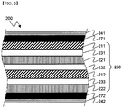
- FIG. 2 is a typical view showing the structure of a battery cell according to an embodiment of the present invention
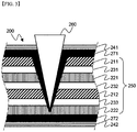
- FIG. 3 is a typical view schematically showing an example in which the battery cell is locally damaged by a metal member.
- a battery cell 200 is configured to have a structure in which an electrode assembly 250, including positive electrodes 211 and 212 and negative electrodes 221 and 222 in a state in which separators 231, 232, and 233 are interposed respectively between the positive electrodes 211 and 212 and the negative electrodes 221 and 222, is mounted in battery cases 241 and 242, and insulative materials 271 and 272 are provided respectively between the electrode assembly 250 and battery cases 241 and 242.
- a metal member 260 penetrates into the battery cell 200 from outside the battery cell 200, a portion of the battery cell 200 may be damaged. Specifically, the metal member 260 may break through the battery case 241 and may then penetrate into the battery cell 200, with the result that the electrode assembly 250 may be locally damaged.
- the insulative material 271 which is provided between the electrode assembly 250 and the battery case 241, is stretched into a shape surrounding the outer surface of the metal member 260, which has penetrated into the battery cell 200, based on the external shape of the metal member.
- the insulative material 271 prevents direct contact between the metal member 260, which has penetrated into the battery cell 200, and the positive electrodes 211 and 212 and the negative electrodes 221 and 222, which constitute the electrode assembly 250 of the battery cell 200, thereby preventing the occurrence of an internal short-circuit in the battery cell 200 or preventing the battery cell 200 from catching fire, thus improving the safety of the battery cell 200.
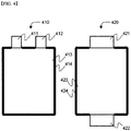
- FIG. 4 is a plan view typically showing regions of battery cells according to other embodiments of the present invention at which insulative elastic members are provided.
- a battery cell 410 according to the present invention is configured such that a positive electrode terminal 411 and a negative electrode terminal 412 protrude from one side of an electrode assembly 413, and another battery cell 420 according to the present invention is configured such that a positive electrode terminal 421 and a negative electrode terminal 422 protrude from opposite sides of an electrode assembly 423.
- An insulative material 414 is provided between the electrode assembly 413 of the battery cell 410 and a case (not shown), and an insulative material 424 is provided between the electrode assembly 423 of the battery cell 420 and a case (not shown).
- the insulative material 414 is provided at the remaining region of the electrode assembly 413, excluding the positive electrode terminal 411 and the negative electrode terminal 412 of the electrode assembly 413, between the electrode assembly 413 and the case
- the insulative material 424 is provided at the remaining region of the electrode assembly 423, excluding the positive electrode terminal 421 and the negative electrode terminal 422 of the electrode assembly 423, between the electrode assembly 423 and the case.
- a stacked type electrode assembly configured to have a structure in which positive electrodes and negative electrodes are stacked in a state in which separators are interposed respectively between the positive electrodes and the negative electrodes, was manufactured. Subsequently, an insulative tape, made of Teflon, was wound to cover the upper surface, the lower surface, and the opposite side surfaces of the electrode assembly. Subsequently, the electrode assembly was received in a pouch-shaped aluminum battery case, and then the battery case was sealed to manufacture a battery cell.
- a battery cell was manufactured in the same manner as in Example 1 except that no insulative tape was wound to cover the upper surface, the lower surface, and the opposite side surfaces of an electrode assembly.
- the battery cells manufactured according to Example 1 and Comparative example 1 were connected to an external device.
- a needle-shaped member having a diameter of 15.8 mm and a weight of 91.9 kg was dropped from a height of 610 mm in order to apply impact to the upper surfaces of the battery cells manufactured according to Example 1 and Comparative example 1.
- the impact test was carried out nine times on different regions of the battery cells manufactured according to Example 1 and Comparative example 1 to check whether internal short-circuits occurred in the battery cells due to direct contact between the needle-shaped member and the electrodes. The results are shown in Table 1.
- Example 1 Comparative example 1 Internal short -circuit First time X ⁇ Second time X ⁇ Third time ⁇ X Fourth time X ⁇ Fifth time X ⁇ Sixth time X ⁇ Seventh time ⁇ ⁇ Eighth time X ⁇ Ninth time X ⁇
- the insulative tape prevents direct contact between the needle-shaped member and the electrodes.
- an insulative material is provided between an electrode assembly and a battery case. Consequently, it is possible to prevent the occurrence of a short-circuit in the battery cell or combustion of the battery cell due to direct contact between electrodes of the electrode assembly and a metal member penetrating into the battery cell when the battery cell is damaged by the metal member.
- the insulative material is applicable to the battery cell regardless of the shape of the electrode assembly. Furthermore, only the insulative material is provided on the outer surface of a conventional electrode assembly or the inner surface of a conventional battery case. Consequently, it is possible to improve the safety of the battery cell using a simple structure.
Landscapes
- Chemical & Material Sciences (AREA)
- Chemical Kinetics & Catalysis (AREA)
- Electrochemistry (AREA)
- General Chemical & Material Sciences (AREA)
- Engineering & Computer Science (AREA)
- Manufacturing & Machinery (AREA)
- Connection Of Batteries Or Terminals (AREA)
- Secondary Cells (AREA)
- Sealing Battery Cases Or Jackets (AREA)
- Battery Mounting, Suspending (AREA)
- Materials Engineering (AREA)
Description
- The present invention relates to a battery cell having a means for preventing short-circuit.
- As energy prices increase due to the depletion of fossil fuels and concern over environmental pollution escalates, the demand for environmentally-friendly alternative energy sources is bound to play an increasing role in the future. Thus, research into techniques for generating various kinds of powers, such as nuclear energy, solar energy, wind energy, and tidal power, is underway, and power storage apparatuses for more efficient use of the generated energy are also drawing a lot of attention.
- In particular, the demand for batteries as energy sources is rapidly increasing as mobile device technology continues to develop and the demand for mobile devices continues to increase. Accordingly, a lot of research on batteries capable of satisfying various needs has been carried out.
- In terms of the shape of batteries, the demand for prismatic secondary batteries or pouch-shaped secondary batteries thin enough to be applied to products, such as cellular phones, is very high. In terms of the material for batteries, on the other hand, the demand for lithium secondary batteries, such as lithium ion batteries and lithium ion polymer batteries, which exhibit high energy density, discharge voltage, and output stability, is also very high.
- In addition, secondary batteries may be classified based on the shape of a battery case of each of the secondary batteries into a cylindrical battery configured to have a structure in which an electrode assembly is mounted in a cylindrical metal container, a prismatic battery configured to have a structure in which an electrode assembly is mounted in a prismatic metal container, and a pouch-shaped battery configured to have a structure in which an electrode assembly is mounted in a pouch-shaped case made of a laminated aluminum sheet.
- Particularly, in recent years, a lot of interest has been directed to a pouch-shaped battery configured to have a structure in which such a stacked or stacked/folded type electrode assembly is mounted in a pouch-shaped battery case made of a laminated aluminum sheet because of low manufacturing costs, light weight, easy modification of the shape thereof, etc. In addition, the use of such a pouch-shaped battery has gradually increased.
- Furthermore, secondary batteries may be classified based on the structure of an electrode assembly, which has a structure in which a positive electrode and a negative electrode are stacked in a state in which a separator is interposed between the positive electrode and the negative electrode. For example, the electrode assembly may be configured to have a jelly-roll (wound) type structure in which a long sheet type positive electrode and a long sheet type negative electrode are wound in a state in which a separator is disposed between the positive electrode and the negative electrode or a stacked type structure in which pluralities of positive electrodes and negative electrodes each having a predetermined size are sequentially stacked in a state in which separators are disposed respectively between the positive electrodes and the negative electrodes. In recent years, in order to solve problems caused by the jelly-roll type electrode assembly and the stacked type electrode assembly, there has been developed a stacked/folded type electrode assembly, which is a combination of the jelly roll type electrode assembly and the stacked type electrode assembly, having an improved structure in which predetermined numbers of positive electrodes and negative electrodes are sequentially stacked in a state in which separators are disposed respectively between the positive electrodes and the negative electrodes to constitute a bi-cell or a full cell, after which a plurality of bi-cells or full cells is sequentially folded while being placed on a separation film.
- One of the principal research projects for secondary batteries is to improve the safety of the secondary batteries. For example, a secondary battery may explode due to high temperature and pressure in the secondary battery which may be caused by an abnormal state of the secondary battery, such as internal short-circuit of the secondary battery, overcharge of the secondary battery with higher than allowed current or voltage, exposure of the secondary battery to high temperature, or deformation of the secondary battery due to drop of the secondary battery or external impact applied to the secondary battery.
- Specifically, if a battery cell is damaged by a metal member penetrating into the battery cell from outside the battery cell, the metal member directly contacts electrodes of an electrode assembly, with the result that an internal short-circuit may occur in the battery cell or the battery cell may catch fire, thereby greatly reducing the safety of the battery cell.
-
FIG. 1 is a typical view schematically showing an example in which a conventional battery cell is locally damaged by a metal member. - Referring to
FIG. 1 , abattery cell 100 is configured to have a structure in which anelectrode assembly 150, including positive electrodes 111 and 112 andnegative electrodes 121 and 122 in a state in whichseparators negative electrodes 121 and 122, is mounted in battery cases 141 and 142. A portion of thebattery cell 100 is damaged by ametal member 160, which has penetrated into thebattery cell 100 from outside thebattery cell 100. - The
metal member 160 has broken through the battery case 141 and then penetrated into thebattery cell 100, with the result that theelectrode assembly 150 has been locally damaged. In this case, the positive electrodes 111 and 112 and thenegative electrodes 121 and 122, which constitute theelectrode assembly 150, directly contact themetal member 160. As a result, an internal short-circuit occurs in thebattery cell 100, with the result that the battery cell may catch fire or explode. - Therefore, there is a high necessity for technology that is capable of fundamentally solving the above problems.
- Further,
US 2013/196215 A1 is concerned with outer casing material for a battery and a lithium secondary battery. - The present invention has been made to solve the above problems and other technical problems that have yet to be resolved. It is an object of the present invention to provide a battery cell having an insulative material provided between an electrode assembly and a battery case for preventing the occurrence of a short-circuit in the battery cell or combustion of the battery cell due to direct contact between electrodes of the electrode assembly and a metal member penetrating into the battery cell when the battery cell is damaged by the metal member, thereby improving the safety of the battery cell.
- In addition, it is another object of the present invention to provide a battery cell to which an insulative material is applicable regardless of the shape of an electrode assembly and which achieves improved safety using a simple structure.
- In accordance with one aspect of the present invention, the above and other objects can be accomplished by the provision of a battery cell as defined in
claim 1. In the battery cell according to the present invention, as described above, the insulative material is provided between the electrode assembly and the battery case. Consequently, it is possible to prevent the occurrence of a short-circuit in the battery cell or combustion of the battery cell due to direct contact between the electrodes of the electrode assembly and the metal member penetrating into the battery cell when the battery cell is damaged by the metal member, thereby improving the safety of the battery cell. - In addition, only the insulative material is provided at the outer surface of a conventional electrode assembly or the inner surface of a conventional battery case regardless of the shape of the electrode assembly. Consequently, it is possible to improve the safety of the battery cell using a simple structure.
- In a concrete example, the insulative material may be provided between the electrode assembly and the battery case in a state in which the insulative material is in tight contact with the outer surface of the electrode assembly or the inner surface of the battery case.
- If the insulative material is provided in the electrode assembly, e.g. between the positive electrode and the negative electrode, the flow of ions between the electrodes may be disturbed by the insulative material. If the insulative material is provided at the outer surface of the battery case, on the other hand, the insulative material is exposed outward. In this case, the insulative material may be weakened by contaminants, may be deteriorated, or may be worn. As a result, the battery case may be partially or entirely exposed outward, and therefore the insulative material may not exhibit desired effects.
- According to the present invention, the insulative material is provided between the electrode assembly and the battery case in a state in which the insulative material is in tight contact with the outer surface of the electrode assembly, which faces the inner surface of the battery case, or the inner surface of the battery case, which faces the outer surface of the electrode assembly. As a result, the insulative material is located between the metal member and the electrodes of the electrode assembly when the battery cell is damaged by the metal member. Consequently, it is possible to prevent direct contact between the metal member and the electrodes of the electrode assembly, thereby preventing the battery cell from catching fire or exploding, thus improving the safety of the battery cell
- However, the present invention is not limited thereto. The insulative material may be provided on both the outer surface of the electrode assembly and the inner surface of the battery case.
- According to the present invention, the insulative material is entirely or partially provided at the remaining region of the electrode assembly, excluding the positive electrode terminal and the negative electrode terminal of the electrode assembly, between the electrode assembly and the battery case.
- That is, the insulative material may be locally provided only at a region of the electrode assembly that is exposed outward and may thus be easily broken, or may be entirely provided at the remaining region of the electrode assembly excluding the positive electrode terminal and the negative electrode terminal of the electrode assembly, depending on the shape of a device to which the battery cell is applied.
- In this case, the insulative material may be provided over 30 to 90%, preferably 50 to 70%, of the entire area of the outer surface of the electrode assembly or the inner surface of the battery case. In addition, the insulative material has a thickness equivalent to 0.1 to 20%, preferably 5 to 10%, of the thickness of the electrode assembly.
- If the insulative material is provided over less than 30% of the entire area of the outer surface of the electrode assembly or the inner surface of the battery case or if the insulative material has a thickness equivalent to less than 0.1% of the thickness of the electrode assembly, it is not possible to exhibit a desired short-circuit prevention effect. On the other hand, if the insulative material is provided at more than 90% of the entire area of the outer surface of the electrode assembly or the inner surface of the battery case or if the insulative material has a thickness equivalent to more than 20% of the thickness of the electrode assembly, it may be difficult to impregnate the electrode assembly with an electrolyte.
- Specifically, when the battery cell is damaged by the metal member, the insulative material is elastically stretched into a shape surrounding the outer surface of the metal member, which has penetrated into the electrode assembly.
- If the insulative material is provided over less than 30% of the entire area of the outer surface of the electrode assembly or the inner surface of the battery case, therefore, it is not possible to effectively prevent direct contact between the metal member and the positive and negative electrodes of the electrode assembly to thus exhibit a desired safety improvement effect, since the insulative material does not cover the entirety of the outer surface of the metal member, which has penetrated into the electrode assembly.
- On the other hand, if the insulative material has a thickness equivalent to less than 0.1% of the thickness of the electrode assembly, the insulative material may be damaged depending on the shape or rigidity of the metal member, whereby it is not possible to exhibit a desired safety improvement effect.
- Meanwhile, the insulative material is not particularly restricted so long as the insulative material is provided at the outer surface of the electrode assembly or the inner surface of the battery case in order to exhibit a desired short-circuit prevention effect and a desired safety improvement effect while not affecting the performance of the battery cell. For example, the insulative material may be insulative paint, Parafilm, foamed rubber, or a mixture thereof.
- In this case, the insulative paint may be at least one selected from a group consisting of acrylonitrile-butadiene rubber (NBR), styrene butadiene rubber (SBR), isobutylene isoprene rubber (IRR), chloroprene rubber (CR), and ethylene propylene diene monomer (EPDM). The insulative paint may be applied to the outer surface of the electrode assembly or the inner surface of the battery case between the electrode assembly and the battery case.
- In addition, the foamed rubber may be natural rubber or synthetic rubber. Specifically, the synthetic rubber may be at least one selected from a group consisting of styrene butadiene rubber, polychloroprene rubber, nitrile rubber, butyl rubber, butadiene rubber, isoprene rubber, ethylene propylene rubber, polysulfide rubber, silicone rubber, fluoro rubber, urethane rubber, and acrylic rubber.
- The structure of the electrode assembly constituting the battery cell according to the present invention is not particularly restricted so long as the electrode assembly is configured to have a structure including a positive electrode, a negative electrode, and a separator interposed between the positive electrode and the negative electrode. Specifically, the electrode assembly may be configured to have a structure in which the positive electrode and the negative electrode are wound in a state in which the separator is interposed between the positive electrode and the negative electrode, a structure in which pluralities of positive electrodes and negative electrodes each having a predetermined size are sequentially stacked in a state in which separators are disposed respectively between the positive electrodes and the negative electrodes, or a structure in which pluralities of positive electrodes and negative electrodes each having a predetermined size are sequentially stacked in a state in which separators are disposed respectively between the positive electrodes and the negative electrodes to constitute a unit cell, after which a plurality of unit cells is sequentially folded while being placed on a separation film.
- In addition, the structure of the battery case constituting the battery cell according to the present invention is not particularly restricted so long as the electrode assembly with the above-stated construction is received in the battery case together with an electrolyte. Specifically, the battery case may be a case configured to have a structure comprising a cylindrical or prismatic container and a cap loaded on the open upper end of the container or a pouch-shaped case made of a laminate sheet including a resin layer and a metal layer.
- The kind of the battery cell according to the present invention is not particularly restricted so long as the battery cell exhibits a desired effect while being configured to have the above-described structure. In a concrete example, the battery cell according to the present invention may be a lithium secondary battery, such as a lithium ion battery or a lithium ion polymer battery, which exhibit high energy density, discharge voltage, and output stability.
- The construction, structure, and manufacturing method of the battery cell, including the lithium secondary battery, are well known in the art to which the present invention pertains, and therefore a detailed description thereof will be omitted.
- In accordance with another aspect of the present invention, there is provided a device including the battery cell with the above-stated construction. The device may be any one selected from a group consisting of a cellular phone, a tablet computer, a laptop computer, a power tool, an electric vehicle, a hybrid electric vehicle, a plug-in hybrid electric vehicle, and a power storage apparatus.
- The device and apparatus are well known in the art to which the present invention pertains, and therefore a detailed description thereof will be omitted.
- The above and other objects, features and other advantages of the present invention will be more clearly understood from the following detailed description taken in conjunction with the accompanying drawings, in which:
-
FIG. 1 is a typical view schematically showing an example in which a conventional battery cell is locally damaged by a metal member; -
FIG. 2 is a typical view showing the structure of a battery cell according to an embodiment of the present invention; -
FIG. 3 is a typical view schematically showing an example in which the battery cell ofFIG. 2 is locally damaged by a metal member; and -
FIG. 4 is a plan view typically showing regions of battery cells according to other embodiments of the present invention at which insulative elastic members are provided. - Now, preferred embodiments of the present invention will be described in detail with reference to the accompanying drawings. It should be noted, however, that the scope of the present invention is not limited by the illustrated embodiments.
-
FIG. 2 is a typical view showing the structure of a battery cell according to an embodiment of the present invention, andFIG. 3 is a typical view schematically showing an example in which the battery cell is locally damaged by a metal member. - Referring to
FIGS. 2 and3 , abattery cell 200 is configured to have a structure in which anelectrode assembly 250, includingpositive electrodes 211 and 212 andnegative electrodes 221 and 222 in a state in whichseparators positive electrodes 211 and 212 and thenegative electrodes 221 and 222, is mounted inbattery cases insulative materials electrode assembly 250 andbattery cases - If a
metal member 260 penetrates into thebattery cell 200 from outside thebattery cell 200, a portion of thebattery cell 200 may be damaged. Specifically, themetal member 260 may break through thebattery case 241 and may then penetrate into thebattery cell 200, with the result that theelectrode assembly 250 may be locally damaged. - In this case, the
insulative material 271, which is provided between theelectrode assembly 250 and thebattery case 241, is stretched into a shape surrounding the outer surface of themetal member 260, which has penetrated into thebattery cell 200, based on the external shape of the metal member. - As a result, the
insulative material 271 prevents direct contact between themetal member 260, which has penetrated into thebattery cell 200, and thepositive electrodes 211 and 212 and thenegative electrodes 221 and 222, which constitute theelectrode assembly 250 of thebattery cell 200, thereby preventing the occurrence of an internal short-circuit in thebattery cell 200 or preventing thebattery cell 200 from catching fire, thus improving the safety of thebattery cell 200. -
FIG. 4 is a plan view typically showing regions of battery cells according to other embodiments of the present invention at which insulative elastic members are provided. - Referring to
FIG. 4 , abattery cell 410 according to the present invention is configured such that apositive electrode terminal 411 and anegative electrode terminal 412 protrude from one side of anelectrode assembly 413, and anotherbattery cell 420 according to the present invention is configured such that apositive electrode terminal 421 and anegative electrode terminal 422 protrude from opposite sides of anelectrode assembly 423. - An
insulative material 414 is provided between theelectrode assembly 413 of thebattery cell 410 and a case (not shown), and aninsulative material 424 is provided between theelectrode assembly 423 of thebattery cell 420 and a case (not shown). Specifically, theinsulative material 414 is provided at the remaining region of theelectrode assembly 413, excluding thepositive electrode terminal 411 and thenegative electrode terminal 412 of theelectrode assembly 413, between theelectrode assembly 413 and the case, and theinsulative material 424 is provided at the remaining region of theelectrode assembly 423, excluding thepositive electrode terminal 421 and thenegative electrode terminal 422 of theelectrode assembly 423, between theelectrode assembly 423 and the case. - Even when the remaining regions of the
battery cell positive electrode terminals negative electrode terminals battery cells battery cells battery cells - A stacked type electrode assembly, configured to have a structure in which positive electrodes and negative electrodes are stacked in a state in which separators are interposed respectively between the positive electrodes and the negative electrodes, was manufactured. Subsequently, an insulative tape, made of Teflon, was wound to cover the upper surface, the lower surface, and the opposite side surfaces of the electrode assembly. Subsequently, the electrode assembly was received in a pouch-shaped aluminum battery case, and then the battery case was sealed to manufacture a battery cell.
- A battery cell was manufactured in the same manner as in Example 1 except that no insulative tape was wound to cover the upper surface, the lower surface, and the opposite side surfaces of an electrode assembly.
- The battery cells manufactured according to Example 1 and Comparative example 1 were connected to an external device. In a state in which an electrical conduction tester was connected to connections between the battery cells and the external device, a needle-shaped member having a diameter of 15.8 mm and a weight of 91.9 kg was dropped from a height of 610 mm in order to apply impact to the upper surfaces of the battery cells manufactured according to Example 1 and Comparative example 1. The impact test was carried out nine times on different regions of the battery cells manufactured according to Example 1 and Comparative example 1 to check whether internal short-circuits occurred in the battery cells due to direct contact between the needle-shaped member and the electrodes. The results are shown in Table 1.
[Table 1] Example 1 Comparative example 1 Internal short -circuit First time X ○ Second time X ○ Third time ○ X Fourth time X ○ Fifth time X ○ Sixth time X ○ Seventh time ○ ○ Eighth time X ○ Ninth time X ○ - It can be seen from Table 1 that, in the battery cell manufactured according to Example 1 of the present invention, configured to have a structure in which the insulative tape is wound to cover the upper surface, the lower surface, and the opposite side surfaces of the electrode assembly, the occurrence of internal short-circuits due to direct contact between the needle-shaped member and the electrodes is more frequently prevented that in the case of the battery cell manufactured according to Comparative example 1.
- This is because, when the needle-shaped member penetrates into the battery cell, the insulative tape prevents direct contact between the needle-shaped member and the electrodes.
- Although the preferred embodiments of the present invention have been disclosed for illustrative purposes, those skilled in the art will appreciate that various modifications, additions and substitutions are possible.
- As is apparent from the above description, in a battery cell according to the present invention, an insulative material is provided between an electrode assembly and a battery case. Consequently, it is possible to prevent the occurrence of a short-circuit in the battery cell or combustion of the battery cell due to direct contact between electrodes of the electrode assembly and a metal member penetrating into the battery cell when the battery cell is damaged by the metal member. In addition, the insulative material is applicable to the battery cell regardless of the shape of the electrode assembly. Furthermore, only the insulative material is provided on the outer surface of a conventional electrode assembly or the inner surface of a conventional battery case. Consequently, it is possible to improve the safety of the battery cell using a simple structure.
Claims (15)
- A battery cell (200, 410, 420) configured such that an electrode assembly (250, 413, 423), comprising a positive electrode (211, 212), a negative electrode (221, 222), and a separator (231, 232, 233) interposed between the positive electrode (211, 212) and the negative electrode (221, 222), is mounted in a receiving part formed in a battery case (241), a positive electrode terminal (411) and a negative electrode terminal (412) protrude from at least one side of the electrode assembly (250, 413, 423), and an insulative material (271, 272, 414, 424) is provided between the electrode assembly (250, 413, 423) and the battery case,
wherein the insulative material (271, 272, 414, 424) is entirely or partially provided over a remaining region of the electrode assembly (250, 413, 423), excluding the positive electrode terminal (411) and the negative electrode terminal (412) of the electrode assembly (250, 413, 423), between the electrode assembly (250, 413, 423) and the battery case (241, 242), characterised in that: the insulative material (271, 272, 414, 424) has a thickness equivalent to 0.1 to 20% of a thickness of the electrode assembly (250, 413, 423). - The battery cell (200, 410, 420) according to claim 1, wherein the insulative material (271, 272, 414, 424) is provided between the electrode assembly (250, 413, 423) and the battery case (241, 242) in a state in which the insulative material (271, 272, 414, 424) is in tight contact with an outer surface of the electrode assembly (250, 413, 423) or an inner surface of the battery case (241, 242).
- The battery cell (200, 410, 420) according to claim 1, wherein the insulative material (271, 272, 414, 424) is provided over 30 to 90% of an entire area of an outer surface of the electrode assembly (250, 413, 423) or an inner surface of the battery case (241, 242).
- The battery cell (200, 410, 420) according to claim 1, wherein the insulative material (271, 272, 414, 424) is insulative paint, Parafilm, foamed rubber, or a mixture thereof.
- The battery cell (200, 410, 420) according to claim 4, wherein the insulative paint is at least one selected from a group consisting of acrylonitrile-butadiene rubber (NBR), styrene butadiene rubber (SBR), isobutylene isoprene rubber (IRR), chloroprene rubber (CR), and ethylene propylene diene monomer (EPDM).
- The battery cell (200, 410, 420) according to claim 4, wherein the foamed rubber is natural rubber or synthetic rubber.
- The battery cell (200, 410, 420) according to claim 6, wherein the synthetic rubber is at least one selected from a group consisting of styrene butadiene rubber, polychloroprene rubber, nitrile rubber, butyl rubber, butadiene rubber, isoprene rubber, ethylene propylene rubber, polysulfide rubber, silicone rubber, fluoro rubber, urethane rubber, and acrylic rubber.
- The battery cell (200, 410, 420) according to claim 1, wherein the electrode assembly (250, 413, 423) is configured to have a structure in which the positive electrode (211, 212) and the negative electrode (221, 222) are wound in a state in which the separator (231, 232, 233) is interposed between the positive electrode (211, 212) and the negative electrode (221, 222).
- The battery cell (200, 410, 420) according to claim 1, wherein the electrode assembly (250, 413, 423) is configured to have a structure in which pluralities of positive electrodes (211, 212) and negative electrodes (221, 222) each having a predetermined size are sequentially stacked in a state in which separators (231, 232, 233) are disposed respectively between the positive electrodes (211, 212) and the negative electrodes (221, 222).
- The battery cell (200, 410, 420) according to claim 1, wherein the electrode assembly (250, 413, 423) is configured to have a structure in which pluralities of positive electrodes (211, 212) and negative electrodes (221, 222) each having a predetermined size are sequentially stacked in a state in which separators (231, 232, 233) are disposed respectively between the positive electrodes (211, 212) and the negative electrodes (221, 222) to constitute a unit cell, after which a plurality of unit cells is sequentially folded while being placed on a separation film.
- The battery cell (200, 410, 420) according to claim 1, wherein the battery case (241, 242) is configured to have a structure comprising a cylindrical or prismatic container and a cap loaded on an open upper end of the container.
- The battery cell (200, 410, 420) according to claim 1, wherein the battery case (241, 242) is a pouch-shaped case made of a laminate sheet comprising a resin layer and a metal layer.
- The battery cell (200, 410, 420) according to claim 1, wherein the battery cell (200, 410, 420) is a lithium secondary battery.
- A device comprising one or more battery cells (200, 410, 420) according to claim 1.
- The device according to claim 14, wherein the device is any one selected from a group consisting of a cellular phone, a tablet computer, a laptop computer, a power tool, an electric vehicle, a hybrid electric vehicle, a plug-in hybrid electric vehicle, and a power storage apparatus.
Priority Applications (1)
| Application Number | Priority Date | Filing Date | Title |
|---|---|---|---|
| PL14866202T PL3051611T3 (en) | 2013-11-26 | 2014-10-22 | Battery cell comprising means for protecting short circuit |
Applications Claiming Priority (2)
| Application Number | Priority Date | Filing Date | Title |
|---|---|---|---|
| KR20130144353 | 2013-11-26 | ||
| PCT/KR2014/009923 WO2015080380A1 (en) | 2013-11-26 | 2014-10-22 | Battery cell comprising means for protecting short circuit |
Publications (4)
| Publication Number | Publication Date |
|---|---|
| EP3051611A1 EP3051611A1 (en) | 2016-08-03 |
| EP3051611A4 EP3051611A4 (en) | 2017-05-10 |
| EP3051611B1 true EP3051611B1 (en) | 2019-12-18 |
| EP3051611B8 EP3051611B8 (en) | 2020-03-11 |
Family
ID=53199291
Family Applications (1)
| Application Number | Title | Priority Date | Filing Date |
|---|---|---|---|
| EP14866202.6A Active EP3051611B8 (en) | 2013-11-26 | 2014-10-22 | Battery cell comprising means for protecting short circuit |
Country Status (6)
| Country | Link |
|---|---|
| US (1) | US10553835B2 (en) |
| EP (1) | EP3051611B8 (en) |
| KR (1) | KR20150060520A (en) |
| CN (1) | CN105684191B (en) |
| PL (1) | PL3051611T3 (en) |
| WO (1) | WO2015080380A1 (en) |
Cited By (1)
| Publication number | Priority date | Publication date | Assignee | Title |
|---|---|---|---|---|
| WO2022189298A1 (en) | 2021-03-11 | 2022-09-15 | Thales | Method for fast and robust deinterleaving of pulse trains |
Families Citing this family (7)
| Publication number | Priority date | Publication date | Assignee | Title |
|---|---|---|---|---|
| KR102186737B1 (en) * | 2016-12-12 | 2020-12-04 | 주식회사 엘지화학 | Battery Cell Comprising Protection Member |
| KR102264633B1 (en) * | 2017-06-16 | 2021-06-15 | 주식회사 엘지에너지솔루션 | Secondary battery |
| KR102326080B1 (en) * | 2018-05-08 | 2021-11-11 | 주식회사 엘지에너지솔루션 | Case for lithium metal secondary battery, lithiium metal secondary batter comprising the same and manufacturing method thereof |
| DE102018128975B4 (en) * | 2018-11-19 | 2024-01-04 | Dr. Ing. H.C. F. Porsche Aktiengesellschaft | Battery housing of a traction battery |
| KR20210090477A (en) * | 2020-01-10 | 2021-07-20 | 에스케이이노베이션 주식회사 | Battery module with improved stability |
| JP7380629B2 (en) * | 2021-03-31 | 2023-11-15 | トヨタ自動車株式会社 | assembled battery |
| CN115224344B (en) * | 2022-01-06 | 2024-08-06 | 惠州市禾信新能源科技有限公司 | Lithium ion power battery module with thermal runaway blocking capability and control method thereof |
Family Cites Families (23)
| Publication number | Priority date | Publication date | Assignee | Title |
|---|---|---|---|---|
| US4818588A (en) * | 1985-11-20 | 1989-04-04 | Dai Nippon Insatsu Kabushiki Kaisha | Packaging materials |
| US5747192A (en) * | 1995-06-07 | 1998-05-05 | Avery Dennison Corporation | Single ply PSA labels for battery applications |
| US6294287B1 (en) | 1999-08-18 | 2001-09-25 | The Gillette Company | Alkaline cell with insulator |
| JP2003123714A (en) * | 2001-10-16 | 2003-04-25 | Nec Tokin Tochigi Ltd | Battery pack |
| TWM240019U (en) * | 2002-08-09 | 2004-08-01 | Tai-Hung Lee | Rotary tube-cutter |
| JP4042613B2 (en) | 2003-04-14 | 2008-02-06 | 日産自動車株式会社 | Bipolar battery |
| JP4238645B2 (en) * | 2003-06-12 | 2009-03-18 | 日産自動車株式会社 | Bipolar battery |
| JP4595302B2 (en) * | 2003-09-04 | 2010-12-08 | 日産自動車株式会社 | Bipolar battery |
| JP4568123B2 (en) * | 2005-01-12 | 2010-10-27 | 三洋電機株式会社 | Non-aqueous electrolyte battery |
| KR100866767B1 (en) | 2006-07-10 | 2008-11-04 | 주식회사 엘지화학 | Secondary battery safety member |
| KR100824874B1 (en) | 2006-08-24 | 2008-04-23 | 삼성에스디아이 주식회사 | Can type secondary battery with protective material |
| KR100716596B1 (en) * | 2007-03-26 | 2007-05-09 | 새한에너테크 주식회사 | Pouch Type Lithium Secondary Battery |
| JP4296522B2 (en) | 2007-08-23 | 2009-07-15 | トヨタ自動車株式会社 | Battery and manufacturing method thereof |
| KR101136799B1 (en) * | 2008-04-18 | 2012-04-19 | 주식회사 엘지화학 | Slim Type Battery Pack |
| US8035246B2 (en) * | 2010-01-07 | 2011-10-11 | American Superconductor Corporation | Torque limiting coupling for wind turbine |
| KR101264553B1 (en) | 2010-11-05 | 2013-05-14 | 주식회사 엘지화학 | Secondary battery having improved safety |
| WO2012060558A2 (en) * | 2010-11-05 | 2012-05-10 | 주식회사 엘지화학 | Enhanced-stability rechargeable battery |
| KR20120058676A (en) * | 2010-11-05 | 2012-06-08 | 주식회사 엘지화학 | Lithium secondary battery having improved safety and battery pack containing the same |
| KR101259356B1 (en) | 2010-11-30 | 2013-04-30 | 주식회사 이노와이어리스 | baseband processing apparatus for LTE base station emulator |
| DE102012206075A1 (en) | 2011-12-15 | 2013-06-20 | Robert Bosch Gmbh | Hard shell cell housing with vapor barrier coating |
| JP6146953B2 (en) | 2012-01-31 | 2017-06-14 | 昭和電工パッケージング株式会社 | Battery exterior material and lithium secondary battery |
| KR101533993B1 (en) * | 2012-04-30 | 2015-07-06 | 주식회사 엘지화학 | Battery Module Having Sheet Member and Film Member |
| CN103325987B (en) * | 2013-05-30 | 2015-08-26 | 广东天劲新能源科技股份有限公司 | Anti-acupuncture lithium battery |
-
2014
- 2014-10-22 US US15/033,438 patent/US10553835B2/en active Active
- 2014-10-22 WO PCT/KR2014/009923 patent/WO2015080380A1/en not_active Ceased
- 2014-10-22 CN CN201480059270.8A patent/CN105684191B/en active Active
- 2014-10-22 PL PL14866202T patent/PL3051611T3/en unknown
- 2014-10-22 EP EP14866202.6A patent/EP3051611B8/en active Active
- 2014-11-04 KR KR1020140151945A patent/KR20150060520A/en not_active Ceased
Non-Patent Citations (1)
| Title |
|---|
| None * |
Cited By (2)
| Publication number | Priority date | Publication date | Assignee | Title |
|---|---|---|---|---|
| WO2022189298A1 (en) | 2021-03-11 | 2022-09-15 | Thales | Method for fast and robust deinterleaving of pulse trains |
| FR3120762A1 (en) | 2021-03-11 | 2022-09-16 | Thales | METHOD FOR RAPID AND ROBUST DEINTERLACING OF PULSE TRAINS |
Also Published As
| Publication number | Publication date |
|---|---|
| EP3051611A4 (en) | 2017-05-10 |
| US10553835B2 (en) | 2020-02-04 |
| PL3051611T3 (en) | 2020-05-18 |
| EP3051611B8 (en) | 2020-03-11 |
| US20160276632A1 (en) | 2016-09-22 |
| CN105684191A (en) | 2016-06-15 |
| KR20150060520A (en) | 2015-06-03 |
| CN105684191B (en) | 2019-02-26 |
| WO2015080380A1 (en) | 2015-06-04 |
| EP3051611A1 (en) | 2016-08-03 |
Similar Documents
| Publication | Publication Date | Title |
|---|---|---|
| EP3051611B1 (en) | Battery cell comprising means for protecting short circuit | |
| US11437683B2 (en) | Battery cell of venting structure using taping | |
| US11329348B2 (en) | Cylindrical battery cell comprising metal can having groove | |
| JP6250567B2 (en) | Sealed battery | |
| KR100914115B1 (en) | Secondary battery | |
| US10026938B2 (en) | Cylindrical lithium-ion cell | |
| KR102331123B1 (en) | Cap Assembly for Cylindrical Battery Cell Comprising Elastic Member | |
| US20100316905A1 (en) | Secondary battery | |
| US20150104672A1 (en) | Safety device of lithium-ion battery | |
| KR102186737B1 (en) | Battery Cell Comprising Protection Member | |
| KR102108113B1 (en) | Electrode Assembly Comprising Separator Having Folded Edge | |
| KR20160111614A (en) | A Battery Cell having Venting Part at The Sealing Part | |
| EP2477257B1 (en) | Secondary battery | |
| KR102522701B1 (en) | The Secondary Battery | |
| KR20060112743A (en) | Cap assembly and a lithium ion secondary battery having the same | |
| KR102164973B1 (en) | Pouch-typed Secondary Battery Comprising Jelly-Roll Electrode Assembly | |
| US20120208075A1 (en) | Secondary Battery | |
| KR20150037309A (en) | Battery Cell Having Battery Case with Shape memory alloys | |
| JP2022540538A (en) | Cylindrical battery and method of manufacturing cylindrical battery | |
| US9887394B2 (en) | Rechargeable battery including fluorescent coating layer | |
| KR101763626B1 (en) | Battery Cell Comprising Conductive Member Having Structure for Improved Safety | |
| KR20140001575U (en) | Battery Cell Having Structure of Improved Safety | |
| KR20130019976A (en) | Method for manufacturing secondary battery | |
| KR101084919B1 (en) | Secondary battery | |
| KR101763606B1 (en) | Secondary Battery Employed with Pressure-Resistant Battery Case |
Legal Events
| Date | Code | Title | Description |
|---|---|---|---|
| PUAI | Public reference made under article 153(3) epc to a published international application that has entered the european phase |
Free format text: ORIGINAL CODE: 0009012 |
|
| 17P | Request for examination filed |
Effective date: 20160428 |
|
| AK | Designated contracting states |
Kind code of ref document: A1 Designated state(s): AL AT BE BG CH CY CZ DE DK EE ES FI FR GB GR HR HU IE IS IT LI LT LU LV MC MK MT NL NO PL PT RO RS SE SI SK SM TR |
|
| AX | Request for extension of the european patent |
Extension state: BA ME |
|
| DAX | Request for extension of the european patent (deleted) | ||
| A4 | Supplementary search report drawn up and despatched |
Effective date: 20170412 |
|
| RIC1 | Information provided on ipc code assigned before grant |
Ipc: H01M 2/02 20060101AFI20170406BHEP Ipc: H01M 10/052 20100101ALN20170406BHEP |
|
| GRAP | Despatch of communication of intention to grant a patent |
Free format text: ORIGINAL CODE: EPIDOSNIGR1 |
|
| STAA | Information on the status of an ep patent application or granted ep patent |
Free format text: STATUS: GRANT OF PATENT IS INTENDED |
|
| RIC1 | Information provided on ipc code assigned before grant |
Ipc: H01M 2/02 20060101AFI20190617BHEP Ipc: H01M 10/052 20100101ALN20190617BHEP |
|
| INTG | Intention to grant announced |
Effective date: 20190717 |
|
| GRAS | Grant fee paid |
Free format text: ORIGINAL CODE: EPIDOSNIGR3 |
|
| GRAJ | Information related to disapproval of communication of intention to grant by the applicant or resumption of examination proceedings by the epo deleted |
Free format text: ORIGINAL CODE: EPIDOSDIGR1 |
|
| GRAL | Information related to payment of fee for publishing/printing deleted |
Free format text: ORIGINAL CODE: EPIDOSDIGR3 |
|
| REG | Reference to a national code |
Ref country code: DE Ref legal event code: R079 Ref document number: 602014058740 Country of ref document: DE Free format text: PREVIOUS MAIN CLASS: H01M0002340000 Ipc: H01M0002020000 |
|
| STAA | Information on the status of an ep patent application or granted ep patent |
Free format text: STATUS: REQUEST FOR EXAMINATION WAS MADE |
|
| GRAR | Information related to intention to grant a patent recorded |
Free format text: ORIGINAL CODE: EPIDOSNIGR71 |
|
| STAA | Information on the status of an ep patent application or granted ep patent |
Free format text: STATUS: GRANT OF PATENT IS INTENDED |
|
| GRAA | (expected) grant |
Free format text: ORIGINAL CODE: 0009210 |
|
| STAA | Information on the status of an ep patent application or granted ep patent |
Free format text: STATUS: THE PATENT HAS BEEN GRANTED |
|
| INTC | Intention to grant announced (deleted) | ||
| RIC1 | Information provided on ipc code assigned before grant |
Ipc: H01M 10/052 20100101ALN20191025BHEP Ipc: H01M 2/02 20060101AFI20191025BHEP |
|
| INTG | Intention to grant announced |
Effective date: 20191106 |
|
| AK | Designated contracting states |
Kind code of ref document: B1 Designated state(s): AL AT BE BG CH CY CZ DE DK EE ES FI FR GB GR HR HU IE IS IT LI LT LU LV MC MK MT NL NO PL PT RO RS SE SI SK SM TR |
|
| REG | Reference to a national code |
Ref country code: CH Ref legal event code: EP |
|
| REG | Reference to a national code |
Ref country code: IE Ref legal event code: FG4D |
|
| REG | Reference to a national code |
Ref country code: DE Ref legal event code: R096 Ref document number: 602014058740 Country of ref document: DE |
|
| REG | Reference to a national code |
Ref country code: AT Ref legal event code: REF Ref document number: 1215570 Country of ref document: AT Kind code of ref document: T Effective date: 20200115 |
|
| REG | Reference to a national code |
Ref country code: CH Ref legal event code: PK Free format text: BERICHTIGUNG B8 |
|
| RAP2 | Party data changed (patent owner data changed or rights of a patent transferred) |
Owner name: LG CHEM, LTD. |
|
| REG | Reference to a national code |
Ref country code: NL Ref legal event code: MP Effective date: 20191218 |
|
| PG25 | Lapsed in a contracting state [announced via postgrant information from national office to epo] |
Ref country code: GR Free format text: LAPSE BECAUSE OF FAILURE TO SUBMIT A TRANSLATION OF THE DESCRIPTION OR TO PAY THE FEE WITHIN THE PRESCRIBED TIME-LIMIT Effective date: 20200319 Ref country code: NO Free format text: LAPSE BECAUSE OF FAILURE TO SUBMIT A TRANSLATION OF THE DESCRIPTION OR TO PAY THE FEE WITHIN THE PRESCRIBED TIME-LIMIT Effective date: 20200318 Ref country code: BG Free format text: LAPSE BECAUSE OF FAILURE TO SUBMIT A TRANSLATION OF THE DESCRIPTION OR TO PAY THE FEE WITHIN THE PRESCRIBED TIME-LIMIT Effective date: 20200318 Ref country code: FI Free format text: LAPSE BECAUSE OF FAILURE TO SUBMIT A TRANSLATION OF THE DESCRIPTION OR TO PAY THE FEE WITHIN THE PRESCRIBED TIME-LIMIT Effective date: 20191218 Ref country code: LT Free format text: LAPSE BECAUSE OF FAILURE TO SUBMIT A TRANSLATION OF THE DESCRIPTION OR TO PAY THE FEE WITHIN THE PRESCRIBED TIME-LIMIT Effective date: 20191218 Ref country code: SE Free format text: LAPSE BECAUSE OF FAILURE TO SUBMIT A TRANSLATION OF THE DESCRIPTION OR TO PAY THE FEE WITHIN THE PRESCRIBED TIME-LIMIT Effective date: 20191218 Ref country code: LV Free format text: LAPSE BECAUSE OF FAILURE TO SUBMIT A TRANSLATION OF THE DESCRIPTION OR TO PAY THE FEE WITHIN THE PRESCRIBED TIME-LIMIT Effective date: 20191218 |
|
| REG | Reference to a national code |
Ref country code: LT Ref legal event code: MG4D |
|
| PG25 | Lapsed in a contracting state [announced via postgrant information from national office to epo] |
Ref country code: HR Free format text: LAPSE BECAUSE OF FAILURE TO SUBMIT A TRANSLATION OF THE DESCRIPTION OR TO PAY THE FEE WITHIN THE PRESCRIBED TIME-LIMIT Effective date: 20191218 Ref country code: RS Free format text: LAPSE BECAUSE OF FAILURE TO SUBMIT A TRANSLATION OF THE DESCRIPTION OR TO PAY THE FEE WITHIN THE PRESCRIBED TIME-LIMIT Effective date: 20191218 |
|
| PG25 | Lapsed in a contracting state [announced via postgrant information from national office to epo] |
Ref country code: AL Free format text: LAPSE BECAUSE OF FAILURE TO SUBMIT A TRANSLATION OF THE DESCRIPTION OR TO PAY THE FEE WITHIN THE PRESCRIBED TIME-LIMIT Effective date: 20191218 |
|
| PG25 | Lapsed in a contracting state [announced via postgrant information from national office to epo] |
Ref country code: PT Free format text: LAPSE BECAUSE OF FAILURE TO SUBMIT A TRANSLATION OF THE DESCRIPTION OR TO PAY THE FEE WITHIN THE PRESCRIBED TIME-LIMIT Effective date: 20200513 Ref country code: NL Free format text: LAPSE BECAUSE OF FAILURE TO SUBMIT A TRANSLATION OF THE DESCRIPTION OR TO PAY THE FEE WITHIN THE PRESCRIBED TIME-LIMIT Effective date: 20191218 Ref country code: CZ Free format text: LAPSE BECAUSE OF FAILURE TO SUBMIT A TRANSLATION OF THE DESCRIPTION OR TO PAY THE FEE WITHIN THE PRESCRIBED TIME-LIMIT Effective date: 20191218 Ref country code: EE Free format text: LAPSE BECAUSE OF FAILURE TO SUBMIT A TRANSLATION OF THE DESCRIPTION OR TO PAY THE FEE WITHIN THE PRESCRIBED TIME-LIMIT Effective date: 20191218 Ref country code: RO Free format text: LAPSE BECAUSE OF FAILURE TO SUBMIT A TRANSLATION OF THE DESCRIPTION OR TO PAY THE FEE WITHIN THE PRESCRIBED TIME-LIMIT Effective date: 20191218 |
|
| PG25 | Lapsed in a contracting state [announced via postgrant information from national office to epo] |
Ref country code: SM Free format text: LAPSE BECAUSE OF FAILURE TO SUBMIT A TRANSLATION OF THE DESCRIPTION OR TO PAY THE FEE WITHIN THE PRESCRIBED TIME-LIMIT Effective date: 20191218 Ref country code: IS Free format text: LAPSE BECAUSE OF FAILURE TO SUBMIT A TRANSLATION OF THE DESCRIPTION OR TO PAY THE FEE WITHIN THE PRESCRIBED TIME-LIMIT Effective date: 20200418 Ref country code: SK Free format text: LAPSE BECAUSE OF FAILURE TO SUBMIT A TRANSLATION OF THE DESCRIPTION OR TO PAY THE FEE WITHIN THE PRESCRIBED TIME-LIMIT Effective date: 20191218 |
|
| REG | Reference to a national code |
Ref country code: DE Ref legal event code: R097 Ref document number: 602014058740 Country of ref document: DE |
|
| REG | Reference to a national code |
Ref country code: AT Ref legal event code: MK05 Ref document number: 1215570 Country of ref document: AT Kind code of ref document: T Effective date: 20191218 |
|
| PLBE | No opposition filed within time limit |
Free format text: ORIGINAL CODE: 0009261 |
|
| STAA | Information on the status of an ep patent application or granted ep patent |
Free format text: STATUS: NO OPPOSITION FILED WITHIN TIME LIMIT |
|
| PG25 | Lapsed in a contracting state [announced via postgrant information from national office to epo] |
Ref country code: DK Free format text: LAPSE BECAUSE OF FAILURE TO SUBMIT A TRANSLATION OF THE DESCRIPTION OR TO PAY THE FEE WITHIN THE PRESCRIBED TIME-LIMIT Effective date: 20191218 Ref country code: ES Free format text: LAPSE BECAUSE OF FAILURE TO SUBMIT A TRANSLATION OF THE DESCRIPTION OR TO PAY THE FEE WITHIN THE PRESCRIBED TIME-LIMIT Effective date: 20191218 |
|
| 26N | No opposition filed |
Effective date: 20200921 |
|
| REG | Reference to a national code |
Ref country code: DE Ref legal event code: R079 Ref document number: 602014058740 Country of ref document: DE Free format text: PREVIOUS MAIN CLASS: H01M0002020000 Ipc: H01M0050100000 |
|
| PG25 | Lapsed in a contracting state [announced via postgrant information from national office to epo] |
Ref country code: AT Free format text: LAPSE BECAUSE OF FAILURE TO SUBMIT A TRANSLATION OF THE DESCRIPTION OR TO PAY THE FEE WITHIN THE PRESCRIBED TIME-LIMIT Effective date: 20191218 Ref country code: SI Free format text: LAPSE BECAUSE OF FAILURE TO SUBMIT A TRANSLATION OF THE DESCRIPTION OR TO PAY THE FEE WITHIN THE PRESCRIBED TIME-LIMIT Effective date: 20191218 |
|
| PG25 | Lapsed in a contracting state [announced via postgrant information from national office to epo] |
Ref country code: IT Free format text: LAPSE BECAUSE OF FAILURE TO SUBMIT A TRANSLATION OF THE DESCRIPTION OR TO PAY THE FEE WITHIN THE PRESCRIBED TIME-LIMIT Effective date: 20191218 |
|
| REG | Reference to a national code |
Ref country code: CH Ref legal event code: PL |
|
| PG25 | Lapsed in a contracting state [announced via postgrant information from national office to epo] |
Ref country code: MC Free format text: LAPSE BECAUSE OF FAILURE TO SUBMIT A TRANSLATION OF THE DESCRIPTION OR TO PAY THE FEE WITHIN THE PRESCRIBED TIME-LIMIT Effective date: 20191218 Ref country code: LU Free format text: LAPSE BECAUSE OF NON-PAYMENT OF DUE FEES Effective date: 20201022 |
|
| REG | Reference to a national code |
Ref country code: BE Ref legal event code: MM Effective date: 20201031 |
|
| PG25 | Lapsed in a contracting state [announced via postgrant information from national office to epo] |
Ref country code: BE Free format text: LAPSE BECAUSE OF NON-PAYMENT OF DUE FEES Effective date: 20201031 Ref country code: CH Free format text: LAPSE BECAUSE OF NON-PAYMENT OF DUE FEES Effective date: 20201031 Ref country code: LI Free format text: LAPSE BECAUSE OF NON-PAYMENT OF DUE FEES Effective date: 20201031 |
|
| PG25 | Lapsed in a contracting state [announced via postgrant information from national office to epo] |
Ref country code: IE Free format text: LAPSE BECAUSE OF NON-PAYMENT OF DUE FEES Effective date: 20201022 |
|
| PG25 | Lapsed in a contracting state [announced via postgrant information from national office to epo] |
Ref country code: TR Free format text: LAPSE BECAUSE OF FAILURE TO SUBMIT A TRANSLATION OF THE DESCRIPTION OR TO PAY THE FEE WITHIN THE PRESCRIBED TIME-LIMIT Effective date: 20191218 Ref country code: MT Free format text: LAPSE BECAUSE OF FAILURE TO SUBMIT A TRANSLATION OF THE DESCRIPTION OR TO PAY THE FEE WITHIN THE PRESCRIBED TIME-LIMIT Effective date: 20191218 Ref country code: CY Free format text: LAPSE BECAUSE OF FAILURE TO SUBMIT A TRANSLATION OF THE DESCRIPTION OR TO PAY THE FEE WITHIN THE PRESCRIBED TIME-LIMIT Effective date: 20191218 |
|
| PG25 | Lapsed in a contracting state [announced via postgrant information from national office to epo] |
Ref country code: MK Free format text: LAPSE BECAUSE OF FAILURE TO SUBMIT A TRANSLATION OF THE DESCRIPTION OR TO PAY THE FEE WITHIN THE PRESCRIBED TIME-LIMIT Effective date: 20191218 |
|
| P01 | Opt-out of the competence of the unified patent court (upc) registered |
Effective date: 20230408 |
|
| REG | Reference to a national code |
Ref country code: DE Ref legal event code: R081 Ref document number: 602014058740 Country of ref document: DE Owner name: LG ENERGY SOLUTION, LTD., KR Free format text: FORMER OWNER: LG CHEM. LTD., SEOUL/SOUL, KR |
|
| REG | Reference to a national code |
Ref country code: GB Ref legal event code: 732E Free format text: REGISTERED BETWEEN 20230824 AND 20230831 |
|
| PGFP | Annual fee paid to national office [announced via postgrant information from national office to epo] |
Ref country code: PL Payment date: 20250924 Year of fee payment: 12 |
|
| PGFP | Annual fee paid to national office [announced via postgrant information from national office to epo] |
Ref country code: GB Payment date: 20250922 Year of fee payment: 12 |
|
| PGFP | Annual fee paid to national office [announced via postgrant information from national office to epo] |
Ref country code: FR Payment date: 20250925 Year of fee payment: 12 |
|
| PGFP | Annual fee paid to national office [announced via postgrant information from national office to epo] |
Ref country code: DE Payment date: 20250922 Year of fee payment: 12 |