EP3051466A1 - Image forming apparatus - Google Patents
Image forming apparatus Download PDFInfo
- Publication number
- EP3051466A1 EP3051466A1 EP16152205.7A EP16152205A EP3051466A1 EP 3051466 A1 EP3051466 A1 EP 3051466A1 EP 16152205 A EP16152205 A EP 16152205A EP 3051466 A1 EP3051466 A1 EP 3051466A1
- Authority
- EP
- European Patent Office
- Prior art keywords
- error
- error handling
- screen
- service man
- forming apparatus
- Prior art date
- Legal status (The legal status is an assumption and is not a legal conclusion. Google has not performed a legal analysis and makes no representation as to the accuracy of the status listed.)
- Granted
Links
Images



Classifications
-
- H—ELECTRICITY
- H04—ELECTRIC COMMUNICATION TECHNIQUE
- H04N—PICTORIAL COMMUNICATION, e.g. TELEVISION
- H04N1/00—Scanning, transmission or reproduction of documents or the like, e.g. facsimile transmission; Details thereof
- H04N1/00002—Diagnosis, testing or measuring; Detecting, analysing or monitoring not otherwise provided for
- H04N1/00071—Diagnosis, testing or measuring; Detecting, analysing or monitoring not otherwise provided for characterised by the action taken
- H04N1/00074—Indicating or reporting
-
- G—PHYSICS
- G03—PHOTOGRAPHY; CINEMATOGRAPHY; ANALOGOUS TECHNIQUES USING WAVES OTHER THAN OPTICAL WAVES; ELECTROGRAPHY; HOLOGRAPHY
- G03G—ELECTROGRAPHY; ELECTROPHOTOGRAPHY; MAGNETOGRAPHY
- G03G15/00—Apparatus for electrographic processes using a charge pattern
- G03G15/50—Machine control of apparatus for electrographic processes using a charge pattern, e.g. regulating differents parts of the machine, multimode copiers, microprocessor control
- G03G15/5016—User-machine interface; Display panels; Control console
- G03G15/502—User-machine interface; Display panels; Control console relating to the structure of the control menu, e.g. pop-up menus, help screens
-
- G—PHYSICS
- G03—PHOTOGRAPHY; CINEMATOGRAPHY; ANALOGOUS TECHNIQUES USING WAVES OTHER THAN OPTICAL WAVES; ELECTROGRAPHY; HOLOGRAPHY
- G03G—ELECTROGRAPHY; ELECTROPHOTOGRAPHY; MAGNETOGRAPHY
- G03G15/00—Apparatus for electrographic processes using a charge pattern
- G03G15/55—Self-diagnostics; Malfunction or lifetime display
-
- G—PHYSICS
- G06—COMPUTING OR CALCULATING; COUNTING
- G06F—ELECTRIC DIGITAL DATA PROCESSING
- G06F3/00—Input arrangements for transferring data to be processed into a form capable of being handled by the computer; Output arrangements for transferring data from processing unit to output unit, e.g. interface arrangements
- G06F3/12—Digital output to print unit, e.g. line printer, chain printer
- G06F3/1201—Dedicated interfaces to print systems
- G06F3/1223—Dedicated interfaces to print systems specifically adapted to use a particular technique
- G06F3/1229—Printer resources management or printer maintenance, e.g. device status, power levels
- G06F3/1234—Errors handling and recovery, e.g. reprinting
-
- G—PHYSICS
- G06—COMPUTING OR CALCULATING; COUNTING
- G06K—GRAPHICAL DATA READING; PRESENTATION OF DATA; RECORD CARRIERS; HANDLING RECORD CARRIERS
- G06K15/00—Arrangements for producing a permanent visual presentation of the output data, e.g. computer output printers
- G06K15/40—Details not directly involved in printing, e.g. machine management, management of the arrangement as a whole or of its constitutive parts
- G06K15/408—Handling exceptions, e.g. faults
-
- H—ELECTRICITY
- H04—ELECTRIC COMMUNICATION TECHNIQUE
- H04N—PICTORIAL COMMUNICATION, e.g. TELEVISION
- H04N1/00—Scanning, transmission or reproduction of documents or the like, e.g. facsimile transmission; Details thereof
- H04N1/00002—Diagnosis, testing or measuring; Detecting, analysing or monitoring not otherwise provided for
- H04N1/00026—Methods therefor
- H04N1/00037—Detecting, i.e. determining the occurrence of a predetermined state
-
- H—ELECTRICITY
- H04—ELECTRIC COMMUNICATION TECHNIQUE
- H04N—PICTORIAL COMMUNICATION, e.g. TELEVISION
- H04N1/00—Scanning, transmission or reproduction of documents or the like, e.g. facsimile transmission; Details thereof
- H04N1/00002—Diagnosis, testing or measuring; Detecting, analysing or monitoring not otherwise provided for
- H04N1/00071—Diagnosis, testing or measuring; Detecting, analysing or monitoring not otherwise provided for characterised by the action taken
- H04N1/00082—Adjusting or controlling
- H04N1/00084—Recovery or repair, e.g. self-repair
-
- H—ELECTRICITY
- H04—ELECTRIC COMMUNICATION TECHNIQUE
- H04N—PICTORIAL COMMUNICATION, e.g. TELEVISION
- H04N1/00—Scanning, transmission or reproduction of documents or the like, e.g. facsimile transmission; Details thereof
- H04N1/0035—User-machine interface; Control console
- H04N1/00405—Output means
- H04N1/00477—Indicating status, e.g. of a job
-
- G—PHYSICS
- G03—PHOTOGRAPHY; CINEMATOGRAPHY; ANALOGOUS TECHNIQUES USING WAVES OTHER THAN OPTICAL WAVES; ELECTROGRAPHY; HOLOGRAPHY
- G03G—ELECTROGRAPHY; ELECTROPHOTOGRAPHY; MAGNETOGRAPHY
- G03G2215/00—Apparatus for electrophotographic processes
- G03G2215/00362—Apparatus for electrophotographic processes relating to the copy medium handling
- G03G2215/00535—Stable handling of copy medium
- G03G2215/00556—Control of copy medium feeding
- G03G2215/00569—Calibration, test runs, test prints
-
- H—ELECTRICITY
- H04—ELECTRIC COMMUNICATION TECHNIQUE
- H04N—PICTORIAL COMMUNICATION, e.g. TELEVISION
- H04N2201/00—Indexing scheme relating to scanning, transmission or reproduction of documents or the like, and to details thereof
- H04N2201/0077—Types of the still picture apparatus
- H04N2201/0094—Multifunctional device, i.e. a device capable of all of reading, reproducing, copying, facsimile transception, file transception
Definitions
- the present invention relates to an image forming apparatus which reduces the time required to start error handling when an error occurs, by enabling easy identification of a test mode corresponding to the occurred error.
- an image forming apparatus such as a printer or a facsimile displays information such as a location and a content of the error on a monitor of the image forming apparatus. Then, a user having noticed the display on the monitor calls a maintenance company, and a service man having received the call performs error handling.
- JP2008-211662A proposes a method in which a monitor of an image forming apparatus presents user processing for handling an occurred error to a user by displaying the processing step by step.
- handling methods classified by model type, error type, and status at the occurrence of an error are stored in advance in a repair database.
- error notification information sent from the image forming apparatus is received
- information indicating a handling method for the occurred error is extracted from the repair database based on model information, error information, and status information of the image forming apparatus which are included in the error notification information, and the extracted information is displayed on the monitor of the image forming apparatus.
- test modes are frequently used when an error occurs.
- operations of various sensors, actuators, and the like in the image forming apparatus are checked to identify the error.
- test mode since there are many and various test modes, search for a test mode to be used takes a long time.
- An object of the present invention is to provide an image forming apparatus which can reduce the time required to start error handling when an error occurs, by enabling easy identification of a test mode corresponding to the occurred error.
- An image forming apparatus which forms an image on a recording medium based on a print data in accordance with some embodiments includes: an error detector configured to detect an error occurring in the image forming apparatus; a storage configured to store pieces of error handling information and test modes in association with each other, each of the pieces of error handling information indicating a method of error handling for each of errors occurring in the image forming apparatus, the test modes to be executed during the error handling; and an error controller configured to read, from the storage, the piece of error handling information and one or more of the test modes corresponding to an error detected by the error detector, generate an error handling screen including the read piece of error handling information and a transition button for transition to a test mode list screen for displaying a list of the read one or more of the test modes, and display the generated error handling screen on a display.
- the error handling screen including the error handling method and the screen transition button which correspond to the occurred error is displayed on the display. Accordingly, a user, a service man, and the like can grasp the error handling method and can also perform error handling by selecting the screen transition button in the error handling screen with the screen transition button to transition to the test mode screen and identifying a test mode corresponding to the error.
- the error handling information may include a flag indicating whether the error handling is executable only by a service man or by both the service man and a user.
- the error controller may be configured to: read, from the storage, the error handling information and the one or more of the test modes corresponding to the error detected by the error detector and display an ID input screen for inputting a user ID or a service man ID on the display; upon the flag included in the read error handling information indicating that the error handling is executable only by the service man and only upon an ID inputted into the ID input screen being the service man ID, generate the error handling screen based on the read error handling information and the read one or more of the test modes and display the generated error handling screen on the display; and upon the flag included in the read error handling information indicating that the error handling is executable by both the service man and the user and upon the ID inputted into the ID input screen being any of the user ID and the service man ID, generate the error handling screen based on the read error handling information and the read one or more of the test modes and display the generated error handling screen
- the service man can easily identify a test mode corresponding to the occurred error out of many test modes by selecting the screen transition button in the error handling screen with the screen transition button, and perform the error handling.
- the error controller may calculate a failure rate of the error handling and rewrite the flag of the error handling whose calculated failure rate exceeds a threshold, to the flag indicating that the error handling is executable only by the service man.
- the error handling when the frequency of failure of error handling by the user is high in a situation where a flag set for the error handling indicates that the error handling is executable by both the service man and the user, the error handling is set to be executable only by the service man hereafter. As a result, the flag can be rewritten such that the error handling is efficiently executed, based on the failure rate of the error handling.
- Fig. 1 is a block diagram illustrating a configuration of the image forming apparatus 1 in Embodiment 1.
- the image forming apparatus 1 is connected to terminal devices (clients) 3, 3, ... of users via a network 2 such as a corporate network.
- the image forming apparatus 1 includes an operation unit 11, a display 12, an image former 13, multiple error sensors 14, a CPU 15, a memory 16, a HDD (hard disk drive) 17, a network Interface (network I/F) 18, and the like.
- the operation unit 11 is operated by a user, a service man, and the like and is provided with various operation switches such as a power switch.
- the operation unit 11 is used to input various types of data such as a user ID, a service man ID, and an error number and to input an error occurrence portion, error processing, and the like in a test mode search screen 12c to be described later.
- the display 12 is used to display an operation status of the image forming apparatus 1, input data of the various operation switches in the operation unit 11, and the like.
- the display 12 is used to display an error handling screen with a test mode screen transition button (hereafter, referred to as error handling screen with the transition button) 12a to be described later, a test mode screen 12b, the test mode search screen 12c, and the like, according to commands from the CPU 15.
- the image former 13 performs image formation by performing operations such as printing image data based on a print job sent from any of the terminal devices 3, 3, ... of the users via the network 2.
- the multiple error sensors 14 function as error detectors and are provided in the image former 13, a not-illustrated sheet feeder, a not-illustrated sheet conveying route, a not-illustrated sheet discharger, and the like inside the image forming apparatus 1.
- the error sensors 14 detect various errors occurring inside the image forming apparatus 11.
- the CPU 15 executes a program stored in the HDD (hard disk drive) 17 to control operations of the entire image forming apparatus 1 and to function as an error controller 15a as will be described later.
- HDD hard disk drive
- the memory 16 temporarily saves and stores various types of information and data processed by the CPU 15.
- the HDD 17 has a program storage 17a and an error management information storage 17b.
- the program storage 17a stores programs such as the program which the CPU 15 executes to control the operations of the entire image forming apparatus 1 and to function as the error controller 15a to be described later.
- the error management information storage 17b stores error handling information indicating a method of error handling for each error and a test mode executed to perform the error handling, in association with each other as error related information. In the test mode, operations of components such as various sensors and actuators in the image forming apparatus 1 are checked to identify the error.
- the network I/F 18 is connected to the terminal devices 3, 3, ... via the network 2.
- the terminal devices 3 are provided for the respective users and perform various types of information processing. Each of the terminal devices 3 is connected to the image forming apparatus 1 in Embodiment 1 via the network 2 and sends the print job to the image forming apparatus 1.
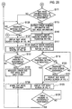
- Figs. 2A and 2B are flowcharts illustrating the operations of the image forming apparatus 1 in Embodiment 1.
- the image former 13 performs image formation by printing images based on the received print job (step S103) under control of the CPU 15.
- step S101 the image formation is performed based on a print job from any of the terminal devices 3, 3, ... for the convenience of description.
- the image formation is not limited to this example and image formation based on, for example, a scan job and a copy job which are generated by the user operating the operation unit 11 and the like may also be performed as a matter of course.
- step S105; NO the error controller 15a of the CPU 15 performs detection of whether an error occurs in the image forming apparatus 1, based on outputs from the error sensors 14 (stepS107).
- step S105; Yes the CPU 15 terminates the image formation based on this print job.
- the error controller 15a of the CPU 15 detects occurrence of an error during the printing (step S107; YES)
- the error controller 15a performs error notification by, for example, displaying an error occurrence screen (not illustrated) indicating occurrence of an error on the display 12 (step S109).
- the error notification can be performed not only by displaying the error occurrence screen (not illustrated) but also by means of audio or the like.
- the error controller 15a of the CPU 15 refers to error management information stored in an error management information storage 17b of the HDD 17, and determines whether a test mode corresponding to the occurred error is registered in the error management information storage 17b (step S111).
- the error controller 15a reads information on the test mode corresponding to the occurred error together with error handling information corresponding to the occurred error, from the error management information storage 17b (step S113).
- the error controller 15a of the CPU 15 combines the read error management information and the read test mode information to generate, for example, an error handling screen with a transition button like the one illustrated in Fig. 3 to be described later (step S115) , and displays the generated error handling screen with the transition button on the display 12 (step S117).
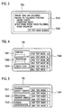
- Fig. 3 is a view illustrating an example of the error handling screen 12a with the transition button displayed on the display 12 by the image forming apparatus 1 in Embodiment 1.
- error handling information 12a1 such as "Error 12345 has occurred. Please fix the following portions. ⁇ Paper feeder ⁇ Conveying route After fixing, please check the following. ⁇ Print operation" and a test mode screen transition button 12a2 for transition to a test mode corresponding to the occurred error and the displayed error handling information.
- step S119 When the user or the service man selects the test mode screen transition button 12a2 in the error handling screen 12a with the transition button like the one illustrated in Fig. 3 (step S119; YES), the error controller 15a of the CPU 15 performs transition from the error handling screen 12a with the transition button like the one illustrated in Fig. 3 to the test mode screen 12b like the one illustrated in Fig. 4 , and displays the test mode screen 12b on the display 12 (step S123).
- Fig. 4 is a view illustrating an example of the test mode screen 12b which is displayed when the test mode screen transition button 12a2 is selected in the error handling screen 12a with the transition button in the image forming apparatus 1 in Embodiment 1.
- an error occurrence portion display field 12b1 for displaying a portion where the error has occurred
- an error processing display field 12b2 for displaying a content of error processing for the occurred error
- an error number display field 12b3 for displaying a number assigned to the occurred error
- a test mode display field 12b4 for displaying one or multiple test modes corresponding to the occurred error.
- the test mode screen 12b is a screen displayed by selecting the test mode screen transition button 12a2 in the error handling screen 12a with the transition button illustrated in Fig. 3 . Accordingly, the "error 12345" which is the number of the occurred and detected error is displayed in the error number display field 12b3 and the occurred error is identified. Moreover, the test modes corresponding to the occurred error are displayed in the test mode display field 12b4. However, no error occurring portion or name of error processing are displayed in the error occurrence portion display field 12b1 and the error processing display field 12b2.
- the service man or the like uses the operation unit 11 to input a number, a password, or the like (hereafter, collectively referred to as password) which is known only by the service man.
- password a number, a password, or the like
- the test mode search screen 12c like the one illustrated in Fig. 5 to be described later is displayed (step S121).
- the test mode screen 12c like the one illustrated in Fig. 4 in which, out of many test modes, the test mode corresponding to the occurred error is identified (step S123).
- Fig. 5 is a view illustrating an example of the test mode search screen 12c for searching a test mode corresponding to an error which has occurred in the image forming apparatus 1 of Embodiment 1.
- the error occurrence portion display field 12b1 and the error processing display field 12b2 are displayed as in the test mode screen 12b illustrated in Fig. 4 .
- an error identification button 12c3 for transition to the test mode screen 12b of the error identified from the error occurrence portion display field 12b1 and the error processing display field 12b2, and a test mode display field 12c4 in which a list of test modes are displayed in the order of numbers assigned thereto and the like.
- the service man After inputting the password or the like for displaying the test mode screen 12b by using the operation unit 11, the service man inputs an error occurrence portion such as "paper feeder” into an error occurrence portion button field 12c1 and also inputs an error processing content such as "error sensor check” into an error processing button field 12c2 in the test mode search screen 12c illustrated in Fig. 5 . Thereafter, when the service man selects the error identification button 12c3, there is displayed the test mode screen 12b like the one illustrated in Fig. 4 in which the test mode corresponding to the occurred error is identified.
- an error occurrence portion such as "paper feeder” into an error occurrence portion button field 12c1
- an error processing content such as "error sensor check”
- step S125; YES the operation returns to step S103 and the image formation processing is continued.
- test mode corresponding to the occurred error needs to be found also when no test mode corresponding to the occurred error is registered in the error management information storage 17b in step S111 (NO).
- step S121 the service man or the like uses the operation unit 11 to input the password known only by the service man.
- step S126 the test mode search screen 12c like the one illustrated in Fig. 6A is displayed (step S127).
- the service man or the like searches for one or multiple test modes corresponding to the occurred error, and the test mode screen 12b like the one illustrated in Fig. 6E is displayed (step S129).
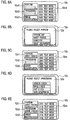
- Steps S127 to S129 are described in detail with reference to screen transition views of Figs. 6A to 6E .
- the error portion selection window 12d is a screen for specifying (identifying) the error occurrence portion in the image forming apparatus 1 such as, for example, "system unit, " "sheet feeder,” “conveyer,” and “sheet discharger” as illustrated in Fig. 6B .
- the "sheet feeder” is displayed in the error occurrence portion button field 12c1 as the error occurrence portion as illustrated in Fig. 6C .
- an error processing selection window 12e is displayed on the test mode search screen 12c like the one illustrated in Fig. 6D .
- the error processing selection window 12e is a screen for specifying (identifying) the error processing to occur in the image forming apparatus 1 such as "sensor check, " "drive check, “ “unit check, “ and “data monitor” as illustrated in Fig. 6D .
- the "drive check” is displayed in the error processing button field 12c2 as the name of the error processing as illustrated in Fig. 6E .
- test mode display field 12c4 By selecting the error occurrence portion and the error processing in the error occurrence portion button field 12c1 and the error processing button field 12c2 of the test mode search screen 12c as described above, a list of test modes associated with the selected error occurrence portion and the selected error processing are displayed in the test mode display field 12c4.
- a test mode is selected out of the many test modes displayed in the test mode display field 12c4 of the test mode search screen 12c illustrated in Fig. 6E , and the selected test mode is executed. Then, when the error handling is successfully performed (step S131; YES), the error controller 15a of the CPU 15 associates the occurred error and the successful test mode with each other (step S133) and stores the error and the test mode in the error management information storage 17b of the HDD 17 as the error management information (step S135).
- the error number of the occurred error displayed in the error number display field 12b3 and the successful test mode displayed in the test mode display field 12b4 in the test mode screen 12b illustrated in Fig. 4 are stored in association with each other.
- the error handling information of the occurred error which is displayed in the error occurrence portion display field 12b1 and the error processing display field 12b2 or which is displayed in the error occurrence portion button field 12c1 and the error processing button field 12c2 of the test mode search screen 12c illustrated in Fig. 5 may also be stored in association with the error number and the test mode.
- step S131 the error controller 15a of the CPU 15 causes the operation to return to the image formation processing of step S103. Note that, when the error handling fails in step S131 (NO), the processing of step S131 is repeatedly executed until the error handling is successfully performed.
- the error controller 15a of the CPU 15 determines "YES" in the determination processing of step S111, and the processing of step S113 and the following steps described above is executed.
- the image forming apparatus 1 in Embodiment 1 reads the error handling information and the test mode which correspond to the occurred error, and displays the error handling screen 12a with the transition button displaying the test mode screen transition button 12a2.
- the user or the service man does not have to input the error occurrence portion, the error processing, and the like in the test mode search screen 12c like the one illustrated in Fig. 5 and find the test mode corresponding to the occurred error out of many test modes.
- the user or the service man can easily identify the test mode corresponding to the occurred error and handle the error.
- the test mode corresponding to the occurred error is not registered in the error management information storage 17b, the test mode corresponding to the occurred error is identified in the test mode search screen 12c illustrated in Figs. 6A to 6E . Then, after the completion of the error handling, the occurred error, the error handling information, and the test mode are stored in association with one another as the error management information.
- the error handling screen 12a with the transition button is generated and displayed based on the error management information of this error.
- the user or the service man can easily identify the test mode corresponding to the occurred error and handle the error.
- the image forming apparatus 1 in Embodiment 2 is characterized in that a flag indicating whether error handling can be executed by both the service man and the user or can be executed only by the service man is set for each error in addition to the error handling information of the error, and the flag is rewritten depending on the number of times the user has desired to perform the error handling, the number of times of error occurrence (error frequency), and the failure rate of the error handling.
- the image forming apparatus 1 in Embodiment 2 thus has the same configuration as the image forming apparatus 1 in Embodiment 1 illustrated in Fig. 1 , different only in the function of the error controller 15a of the CPU 15. Accordingly, operations of the image forming apparatus 1 in Embodiment 2 are described with reference to the configuration of the image forming apparatus 1 illustrated in Fig. 1 .
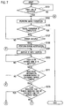
- Fig. 7 is a flowchart illustrating the operations of the image forming apparatus 1 in Embodiment 2. Note that the same processing steps as that in the flowcharts of the image forming apparatus 1 in Embodiment 1 illustrated in Figs. 2A and 2B are described while being denoted by the same step numbers.
- step S109 is the same as the processing in the image forming apparatus 1 in Embodiment 1 illustrated in Fig. 2A .
- the image former 13 performs printing based on the received print job under the control of the CPU 15 (step S103).
- step S105 the error controller 15a of the CPU 15 performs detection of whether an error occurs, based on the outputs from the error sensors 14 (step S107).
- step S107 the image formation based on this print job is completed.
- the error controller 15a of the CPU 15 detects occurrence of an error based on the outputs from the error sensors 14 (step S107; YES) before the completion of the image formation (step S105; NO)
- the error controller 15a performs the error notification by, for example, displaying the error occurrence screen (not illustrated) on the display 12 (step S109). Note that the processing up to this point is the same as that in the image forming apparatus 1 in Embodiment 1.
- the error controller 15a of the CPU 15 in Embodiment 2 displays an ID input screen (not illustrated) for inputting a user ID or a service man ID on the display 12 (step S201), and determines whether the user or the service man inputs the user ID or the service man ID (step S203).
- the error controller 15a of the CPU 15 in Embodiment 2 refers to the error management information stored in the error management information storage 17b of the HDD 17, and determines whether a test mode corresponding to the occurred error is registered in the error management information storage 17b (step S111).
- the error controller 15a of the CPU 15 in Embodiment 2 causes the operation to proceed to the processing of step S127 in Fig. 2B as in the image forming apparatus 1 in Embodiment 1.
- the error controller 15a of the CPU 15 in Embodiment 2 determines whether a flag set for error handling information of the occurred error indicates that error handling can be executed only by the service man (step S205). Note that the flag may be set directly for each error, instead of being set for the error handling information corresponding to the error.
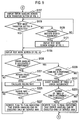
- step S205 when the flag set for the error handling information of the occurred error indicates that the error handling can be executed only by the service man (step S205; YES), the operation proceeds to the flowchart illustrated in Fig. 8 . Meanwhile, when the flag indicates that the error handling can be executed not only by the service man but by both the service man and the user (step S205; NO), the operation proceeds to the flowchart illustrated in Fig. 9 .
- Fig. 8 is a flowchart illustrating processing performed when the flag set for the error handling information of the occurred error indicates that the error handling can be executed only by the service man. In the processing of Fig. 8 , since the flag indicates that the error handling can be executed only by the service man, the error handling is executed only by the service man.
- the error controller 15a of the CPU 15 in Embodiment 2 first determines whether the ID inputted in the ID input processing of step S203 is the service man ID (step S207).
- the ID inputted in step S203 being the service man ID means that the service man is executing the error handling. Accordingly, the error controller 15a of the CPU 15 in Embodiment 2 displays the error handling screen 12a with the transition button (see Fig. 3 ) (step S117).
- the error controller 15a of the CPU 15 in Embodiment 2 performs transition from the error handling screen 12a with the transition button (see Fig. 3 ) to the test mode screen 12b (see Fig. 4 ), and displays the test mode screen 12b on the display 12 (step S123).
- test mode screen 12b In order to display the test mode screen 12b (see Fig. 4 ) on the display 12 without the selection of the test mode screen transition button 12a2 (step S119; NO), the following operations are required. First, a password is inputted and matched (step S120; YES), then the test mode search screen 12c like the one illustrated in Fig. 5 is displayed on the display 12 (step S121), and a test mode corresponding to the occurred error is identified from the error occurrence portion, the error processing, and the like and displayed. This is cumbersome and takes time.
- step S125; YES the operation returns to the image formation processing of step S103.
- the image forming apparatus 1 displays, on the display 12, the error handling screen 12a with the transition button displaying the test mode screen transition button 12a2, only if the inputted ID is the service man ID.
- test mode search screen 12c like the one illustrated in Fig. 5 on the display 12 (step S121) and find the test mode corresponding to the occurred error out of the many test modes.
- the service man can easily identify the test mode corresponding to the occurred error and handle the error.
- step S207 when the ID inputted in step S203 is not an service man ID (step S207; NO), the person who is trying to execute the error handling is a person other than the service man such as the user, although the flag indicating that the error handling can be executed only by the service man is set for the occurred error.
- the error controller 15a of the CPU 15 in Embodiment 2 displays, on the display 12, an error handler selection screen (not illustrated) which, for example, makes the user or the like choose whether to perform the error handling by him/herself or to call the service man and request the error handling (step S209), and make the user or the like choose the person to perform the error handling (step S211).
- the error controller 15a of the CPU 15 of Embodiment 2 counts the number of times the user has desired to perform the error handling by him/herself (step S213), and updates and stores the number in the memory 16 or the like (step S215).
- the error controller 15a of the CPU 15 in Embodiment 2 determines whether the number of times the user has desired to perform the error handling by him/herself is greater than a predetermined threshold (step S217).
- the error controller 15a rewrites the flag for this error handling to the flag indicating that the error handling can be executed by both the service man and the user (step S219), provided that the number of times the user has desired to perform the error handling by him/herself is greater than the predetermined threshold (step S217; YES).
- step S217 the operation proceeds to the flowchart of Fig. 9 , and the user executes the error handling by him/herself.
- the flag set for a certain error indicates that the error handling can be executed only by the service man (step S205; YES) but the user desires to perform the error handling by him/herself and the number of times the user has desired to perform the error handling exceeds the predetermined threshold (step S217; YES)
- the flag set for the certain error is rewritten to the flag indicating that the error handling can be executed by both the service man and the user in the flag rewriting processing of step S219.
- the operation proceeds to the flowchart of Fig. 9 and the user can also execute the error handling.
- step S211 when the user desires that the error handling is to be performed by the service man in the determination processing of step S211 (step S211; NO), the operation returns to the ID input screen display processing of step S201 in Fig. 7 , and the user lets the service man input the service man ID and perform the error handling.
- the determination result is "YES" in the determination processing of step S207, and the service man executes the processing of steps S117 and the following steps and performs the error handling.
- Fig. 9 is a flowchart illustrating processing performed when the flag set for the error handling information of the occurred error indicates that the error handling can be executed by both the service man and the user. In the processing of Fig. 9 , the service man and the user execute the error handling.
- step S205 When the flag set for the error handling information of the occurred error indicates that the error handling can be executed by both the service man and the user in the determination processing of step S205 in Fig. 7 (step S205; NO), the error controller 15a of the CPU 15 in Embodiment 2 displays the error handling screen 12a with the transition button (see Fig. 3 ) as illustrated in Fig. 9 (step S117).
- the error controller 15a of the CPU 15 in Embodiment 2 performs switching from the error handling screen 12a with the transition button (see Fig. 3 ) to the test mode screen 12b (see Fig. 4 ) displaying a test mode corresponding the occurred error, and displays the test mode screen 12b (step S123).
- the user or the service man can skip the processing of step S121 in which the test mode search screen 12c like the one illustrated in Fig. 5 is displayed on the display 12 and the user or the service man finds the test mode corresponding to the occurred error out of the many test modes in the test mode search screen 12c. Accordingly, the user or the service man can easily identify the test mode corresponding to the occurred error and handle the error.
- the error controller 15a of the CPU 15 in Embodiment 2 displays the test mode search screen 12c like the one illustrated in Fig. 5 (step S121).
- the error controller 15a thereby makes the user or the service man find the test mode corresponding to the occurred error out of the many test modes, and displays the test mode screen like the one illustrated in Fig. 4 (step S123).
- step S125 the error controller 15a of the CPU 15 in Embodiment 2 determines whether a person failed to perform the error handling is the user (step S221). Note that the fact of failure is inputted by the user.
- the error controller 15a of the CPU 15 in Embodiment 2 calculates the failure rate (step S223) and stores the failure rate in the memory 16 or the like, provided that the person failed to perform the error handling is the user (step S221; YES).
- the failure rate is obtained by, for example, dividing the number of times of error handling failure by the number of times of performing the error handling.
- the error controller 15a of the CPU 15 in Embodiment 2 determines whether the failure rate of the error handling is greater than a predetermined threshold such as, for example, 80% (step S225).
- the error controller 15a rewrites the flag indicating that the error handling can be executed by both the service man and the user to the flag indicating that the error handling can be executed only by the service man (step S227), provided that the failure rate of the error handling is greater than the predetermined threshold (step S225; YES).
- the flag is rewritten to the flag indicating that the error handling can be executed only by the service man in the processing of step S227. Accordingly, when the same error occurs later, the service man executes the error handling and the error handling can be thus executed efficiently.
- step S221; NO when the person failed to perform the error handling is determined to be the service man (step S221; NO) or when the user fails to perform the error handling (step S221; YES) but the failure rate of the error handling is equal to or less than the predetermined threshold (step S225; NO), the rewriting of the flag in step S227 is not executed and the flag is left be the flag indicating that the error handling can be executed by both the service man and the user.
- step S125 when the service man or the user successfully performs the error handling (step S125; YES), the error controller 15a of the CPU 15 in Embodiment 2 determines whether the error handling is performed by the user (step S229).
- the error controller 15a of the CPU 15 in Embodiment 2 counts the number of times of error occurrence (step S231) and determines whether the number of times of error occurrence (error frequency) is greater than a predetermined threshold (step S233). Then, the error controller 15a rewrites the flag to the flag indicating that the error handling can be executed only by the service man (step S235), provided that the number of times of error occurrence is greater than the predetermined threshold such as, for example, 10 (YES). Then, the operation proceeds to the image formation processing of step S103 illustrated in Fig. 7 .
- the error handling for a certain error is executed by the user and the number of times of occurrence of this error is greater than the predetermined threshold, it is likely that the error handling by the user is insufficient because the same error occurs repeatedly or that a part in a portion where the error has occurred has reached the end of life and the same error occurs repeatedly.
- the flag of the error is thus rewritten to the flag indicating that the error handling can be executed only by the service man in the processing of step S229. Accordingly, when the same error occurs later, the service man executes the error handling, and the error handling or part replacement can be efficiently performed by the service man.
- step S221; NO when the person performing the error handling is not the user but the service man (step S221; NO) or when the number of times of error occurrence (error frequency) is less than the predetermined threshold (step S233; NO), the error controller 15a of the CPU 15 in Embodiment 2 does not execute the rewriting processing of the flag in step S235, and the flag is left to be the flag indicating that the error handling can be executed by both the service man and the user.
- the image forming apparatus 1 in Embodiment 2 like the image forming apparatus 1 in Embodiment 1, reads the error handling information and the test mode which correspond to the occurred error, and displays the error handling screen 12a with the transition button (see Fig. 3 ).
- the test mode screen transition button 12a2 in the error handling screen 12a with the transition button see Fig. 3
- the test mode screen 12b see Fig. 4
- displaying test modes corresponding to the occurred error can be displayed.
- the user or the service man can easily identify the test mode corresponding to the occurred error and handle the error.
- the image forming apparatus 1 in Embodiment 2 displays, on the display 12, the error handling screen 12a with the transition button displaying the test mode screen transition button 12a2, only if the inputted ID is the service man ID. Accordingly, in this case, the service man can easily identify a test mode corresponding to the occurred error out of many test modes by selecting the test mode screen transition button 12a2 in the error handling screen 12a with the transition button, and perform the error handling.
- the image forming apparatus 1 in Embodiment 2 calculates the failure rate of the error handling.
- the failure rate of the error handling exceeds the predetermined threshold, the flag is rewritten to the flag indicating that the error handling can be executed only by the service man. Since the error handling is hereafter set as the error handling which can be executed only by the service man in this case, the error handling is efficiently executed based on the failure rate of the error handling.
- the image forming apparatus 1 in Embodiment 2 counts the number of times of error occurrence. When the number of times of error occurrence is greater than the predetermined threshold, the flag is rewritten to the flag indicating that the error handling can be executed only by the service man. In this case, it is likely that the error handling by the user is insufficient because the same error occurs repeatedly or that a part in a portion where the error has occurred has reached the end of life and the same error occurs repeatedly. Thus, rewriting the flag to the flag indicating that the error handling can be executed only by the service man allows the service man to efficiently perform the error handling or execute part replacement when the same error occurs later.
Landscapes
- Engineering & Computer Science (AREA)
- Multimedia (AREA)
- Signal Processing (AREA)
- General Engineering & Computer Science (AREA)
- General Physics & Mathematics (AREA)
- Physics & Mathematics (AREA)
- Health & Medical Sciences (AREA)
- General Health & Medical Sciences (AREA)
- Biomedical Technology (AREA)
- Theoretical Computer Science (AREA)
- Human Computer Interaction (AREA)
- Microelectronics & Electronic Packaging (AREA)
- Facsimiles In General (AREA)
- Control Or Security For Electrophotography (AREA)
- Accessory Devices And Overall Control Thereof (AREA)
Abstract
Description
- The present invention relates to an image forming apparatus which reduces the time required to start error handling when an error occurs, by enabling easy identification of a test mode corresponding to the occurred error.
- When an error occurs, an image forming apparatus such as a printer or a facsimile displays information such as a location and a content of the error on a monitor of the image forming apparatus. Then, a user having noticed the display on the monitor calls a maintenance company, and a service man having received the call performs error handling.
- However, such error handling requires quite a long time, because when an error occurs, the image forming apparatus always has to prompt the user to call the maintenance company, and let the service man perform the error handling. Japanese Patent Application Publication No.
2008-211662 JP2008-211662A - For the image forming apparatus described in
JP2008-211662A - In the image forming apparatus described in
JP2008-211662A - However, since there are many and various test modes, search for a test mode to be used takes a long time.
- In a recent image forming apparatus including functions of photocopying, FAX, scanner, and the like in addition to the printing function, in particular, the number of various error sensors, actuators, and the like has increased due to these various functions. As a result, the number of portions (parts, areas, and the like) to be fixed in the error handling has increased, and the number of the test modes has reached several thousands in some cases. Accordingly, when an error occurs, the service man or the user needs to find an appropriate test mode out of the several thousand test modes, and this takes quite a long time.
- For example, even when the handling method based on the error information is displayed on the monitor of the image forming apparatus as in the image forming apparatus described above, searching of the test mode takes time, and a long time is required for the error handling. Moreover, an unskilled service man unfamiliar with the test modes cannot perform the error handling because the service man does not know which test mode to execute.
- An object of the present invention is to provide an image forming apparatus which can reduce the time required to start error handling when an error occurs, by enabling easy identification of a test mode corresponding to the occurred error.
- An image forming apparatus which forms an image on a recording medium based on a print data in accordance with some embodiments includes: an error detector configured to detect an error occurring in the image forming apparatus; a storage configured to store pieces of error handling information and test modes in association with each other, each of the pieces of error handling information indicating a method of error handling for each of errors occurring in the image forming apparatus, the test modes to be executed during the error handling; and an error controller configured to read, from the storage, the piece of error handling information and one or more of the test modes corresponding to an error detected by the error detector, generate an error handling screen including the read piece of error handling information and a transition button for transition to a test mode list screen for displaying a list of the read one or more of the test modes, and display the generated error handling screen on a display.
- In the configuration described above, when an error occurs, the error handling screen including the error handling method and the screen transition button which correspond to the occurred error is displayed on the display. Accordingly, a user, a service man, and the like can grasp the error handling method and can also perform error handling by selecting the screen transition button in the error handling screen with the screen transition button to transition to the test mode screen and identifying a test mode corresponding to the error.
- The error handling information may include a flag indicating whether the error handling is executable only by a service man or by both the service man and a user. The error controller may be configured to: read, from the storage, the error handling information and the one or more of the test modes corresponding to the error detected by the error detector and display an ID input screen for inputting a user ID or a service man ID on the display; upon the flag included in the read error handling information indicating that the error handling is executable only by the service man and only upon an ID inputted into the ID input screen being the service man ID, generate the error handling screen based on the read error handling information and the read one or more of the test modes and display the generated error handling screen on the display; and upon the flag included in the read error handling information indicating that the error handling is executable by both the service man and the user and upon the ID inputted into the ID input screen being any of the user ID and the service man ID, generate the error handling screen based on the read error handling information and the read one or more of the test modes and display the generated error handling screen on the display.
- In the configuration described above, the service man can easily identify a test mode corresponding to the occurred error out of many test modes by selecting the screen transition button in the error handling screen with the screen transition button, and perform the error handling.
- Upon the flag included in the read error handling information indicating that the error handling is executable by both the service man and the user and upon failure of the error handling performed by an operation of the user referring to the error handling screen displayed on the display, the error controller may calculate a failure rate of the error handling and rewrite the flag of the error handling whose calculated failure rate exceeds a threshold, to the flag indicating that the error handling is executable only by the service man.
- In the configuration described above, when the frequency of failure of error handling by the user is high in a situation where a flag set for the error handling indicates that the error handling is executable by both the service man and the user, the error handling is set to be executable only by the service man hereafter. As a result, the flag can be rewritten such that the error handling is efficiently executed, based on the failure rate of the error handling.
-
-
Fig. 1 is a block diagram illustrating a configuration of an image forming apparatus inEmbodiment 1 of the present invention. -
Figs. 2A and2B are flowcharts illustrating operations of the image forming apparatus inEmbodiment 1. -
Fig. 3 is a view illustrating an example of an error handling screen with a test mode screen transition button which is displayed on a display by the image forming apparatus inEmbodiment 1. -
Fig. 4 is a view illustrating an example of a test mode screen which is displayed when the test mode screen transition button of the error handling screen with the transition button is selected in the image forming apparatus inEmbodiment 1. -
Fig. 5 is a view illustrating an example of a test mode search screen for searching a test mode corresponding to an error which has occurred in the image forming apparatus inEmbodiment 1. -
Figs. 6A to 6E are views illustrating a procedure for displaying the test mode screen illustrated inFig. 4 from the test mode search screen illustrated inFig. 5 . -
Fig. 7 is a flowchart illustrating operations of the image forming apparatus inEmbodiment 2 of the present invention. -
Fig. 8 is continuation of the flowchart inFig. 7 illustrating the operations of the image forming apparatus, and is a flowchart in the situation where a flag indicates that error handling can be executed only by a service man. -
Fig. 9 is continuation of the flowchart inFig. 7 illustrating the operations of the image forming apparatus, and is a flowchart in the situation where the flag indicates that the error handling can be executed by both the service man and a user. - In the following detailed description, for purposes of explanation, numerous specific details are set forth in order to provide a thorough understanding of the disclosed embodiments. It will be apparent, however, that one or more embodiments may be practiced without these specific details. In other instances, well-known structures and devices are schematically shown in order to simplify the drawing.
- Description will be hereinbelow provided for embodiments of the present invention by referring to the drawings. It should be noted that the same or similar parts and components throughout the drawings will be denoted by the same or similar reference signs, and that descriptions for such parts and components will be omitted or simplified. In addition, it should be noted that the drawings are schematic and therefore different from the actual ones.
- An
image forming apparatus 1 inEmbodiments -
Fig. 1 is a block diagram illustrating a configuration of theimage forming apparatus 1 inEmbodiment 1. - As illustrated in
Fig. 1 , theimage forming apparatus 1 is connected to terminal devices (clients) 3, 3, ... of users via anetwork 2 such as a corporate network. - The
image forming apparatus 1 includes anoperation unit 11, adisplay 12, an image former 13,multiple error sensors 14, aCPU 15, amemory 16, a HDD (hard disk drive) 17, a network Interface (network I/F) 18, and the like. - The
operation unit 11 is operated by a user, a service man, and the like and is provided with various operation switches such as a power switch. In theimage forming apparatus 1, theoperation unit 11 is used to input various types of data such as a user ID, a service man ID, and an error number and to input an error occurrence portion, error processing, and the like in a testmode search screen 12c to be described later. - The
display 12 is used to display an operation status of theimage forming apparatus 1, input data of the various operation switches in theoperation unit 11, and the like. InEmbodiment 1, thedisplay 12 is used to display an error handling screen with a test mode screen transition button (hereafter, referred to as error handling screen with the transition button) 12a to be described later, atest mode screen 12b, the testmode search screen 12c, and the like, according to commands from theCPU 15. - The image former 13 performs image formation by performing operations such as printing image data based on a print job sent from any of the
terminal devices network 2. - The
multiple error sensors 14 function as error detectors and are provided in the image former 13, a not-illustrated sheet feeder, a not-illustrated sheet conveying route, a not-illustrated sheet discharger, and the like inside theimage forming apparatus 1. Theerror sensors 14 detect various errors occurring inside theimage forming apparatus 11. - The
CPU 15 executes a program stored in the HDD (hard disk drive) 17 to control operations of the entireimage forming apparatus 1 and to function as anerror controller 15a as will be described later. - The
memory 16 temporarily saves and stores various types of information and data processed by theCPU 15. - The
HDD 17 has aprogram storage 17a and an errormanagement information storage 17b. Theprogram storage 17a stores programs such as the program which theCPU 15 executes to control the operations of the entireimage forming apparatus 1 and to function as theerror controller 15a to be described later. The errormanagement information storage 17b stores error handling information indicating a method of error handling for each error and a test mode executed to perform the error handling, in association with each other as error related information. In the test mode, operations of components such as various sensors and actuators in theimage forming apparatus 1 are checked to identify the error. - The network I/
F 18 is connected to theterminal devices network 2. - The
terminal devices 3 are provided for the respective users and perform various types of information processing. Each of theterminal devices 3 is connected to theimage forming apparatus 1 inEmbodiment 1 via thenetwork 2 and sends the print job to theimage forming apparatus 1. - Next, operations of the
image forming apparatus 1 inEmbodiment 1 configured as described above are described with reference to the drawings. -
Figs. 2A and2B are flowcharts illustrating the operations of theimage forming apparatus 1 inEmbodiment 1. - First, in the
image forming apparatus 1, the user turns on the power switch in theoperation unit 11. Then, when the image former 13 receives a print job from any of theterminal devices network 2 and the like (step S101; YES), the image former 13 performs image formation by printing images based on the received print job (step S103) under control of theCPU 15. Here, description is given of the example in which the image formation is performed based on a print job from any of theterminal devices operation unit 11 and the like may also be performed as a matter of course. - Until the image formation is completed (step S105; NO), the
error controller 15a of theCPU 15 performs detection of whether an error occurs in theimage forming apparatus 1, based on outputs from the error sensors 14 (stepS107). When the image formation is completed without occurrence of an error (step S105; Yes), theCPU 15 terminates the image formation based on this print job. - Meanwhile, when the
error controller 15a of theCPU 15 detects occurrence of an error during the printing (step S107; YES), theerror controller 15a performs error notification by, for example, displaying an error occurrence screen (not illustrated) indicating occurrence of an error on the display 12 (step S109). Note that the error notification can be performed not only by displaying the error occurrence screen (not illustrated) but also by means of audio or the like. - Next, the
error controller 15a of theCPU 15 refers to error management information stored in an errormanagement information storage 17b of theHDD 17, and determines whether a test mode corresponding to the occurred error is registered in the errormanagement information storage 17b (step S111). - In this case, when the test mode corresponding to the occurred error is registered in the error
management information storage 17b (step S111; YES), theerror controller 15a reads information on the test mode corresponding to the occurred error together with error handling information corresponding to the occurred error, from the errormanagement information storage 17b (step S113). - Next, the
error controller 15a of theCPU 15 combines the read error management information and the read test mode information to generate, for example, an error handling screen with a transition button like the one illustrated inFig. 3 to be described later (step S115) , and displays the generated error handling screen with the transition button on the display 12 (step S117). -
Fig. 3 is a view illustrating an example of theerror handling screen 12a with the transition button displayed on thedisplay 12 by theimage forming apparatus 1 inEmbodiment 1. - As illustrated in
Fig. 3 , in theerror handling screen 12a with the transition button, there is displayed error handling information 12a1 such as "Error 12345 has occurred. Please fix the following portions. ·Paper feeder ·Conveying route After fixing, please check the following. ·Print operation" and a test mode screen transition button 12a2 for transition to a test mode corresponding to the occurred error and the displayed error handling information. - When the user or the service man selects the test mode screen transition button 12a2 in the
error handling screen 12a with the transition button like the one illustrated inFig. 3 (step S119; YES), theerror controller 15a of theCPU 15 performs transition from theerror handling screen 12a with the transition button like the one illustrated inFig. 3 to thetest mode screen 12b like the one illustrated inFig. 4 , and displays thetest mode screen 12b on the display 12 (step S123). -
Fig. 4 is a view illustrating an example of thetest mode screen 12b which is displayed when the test mode screen transition button 12a2 is selected in theerror handling screen 12a with the transition button in theimage forming apparatus 1 inEmbodiment 1. - As illustrated in
Fig. 4 , in thetest mode screen 12b, there are displayed an error occurrence portion display field 12b1 for displaying a portion where the error has occurred, an error processing display field 12b2 for displaying a content of error processing for the occurred error, an error number display field 12b3 for displaying a number assigned to the occurred error, and a test mode display field 12b4 for displaying one or multiple test modes corresponding to the occurred error. - In the example of
Fig. 4 , thetest mode screen 12b is a screen displayed by selecting the test mode screen transition button 12a2 in theerror handling screen 12a with the transition button illustrated inFig. 3 . Accordingly, the "error 12345" which is the number of the occurred and detected error is displayed in the error number display field 12b3 and the occurred error is identified. Moreover, the test modes corresponding to the occurred error are displayed in the test mode display field 12b4. However, no error occurring portion or name of error processing are displayed in the error occurrence portion display field 12b1 and the error processing display field 12b2. - Meanwhile, in order to display the
test mode screen 12b ofFig. 4 without the selection of the test mode screen transition button 12a2 in theerror handling screen 12a with the transition button in step S119 (NO), the service man or the like uses theoperation unit 11 to input a number, a password, or the like (hereafter, collectively referred to as password) which is known only by the service man. When the inputted password matches a password stored in advance (step S120; YES), the testmode search screen 12c like the one illustrated inFig. 5 to be described later is displayed (step S121). Then, by inputting the error occurrence portion and the error processing in the displayed testmode search screen 12c, there is displayed the test mode screen like the one illustrated inFig. 4 in which, out of many test modes, the test mode corresponding to the occurred error is identified (step S123). -
Fig. 5 is a view illustrating an example of the testmode search screen 12c for searching a test mode corresponding to an error which has occurred in theimage forming apparatus 1 ofEmbodiment 1. - In the test
mode search screen 12c illustrated inFig. 5 , the error occurrence portion display field 12b1 and the error processing display field 12b2 are displayed as in thetest mode screen 12b illustrated inFig. 4 . In addition, there are displayed an error identification button 12c3 for transition to thetest mode screen 12b of the error identified from the error occurrence portion display field 12b1 and the error processing display field 12b2, and a test mode display field 12c4 in which a list of test modes are displayed in the order of numbers assigned thereto and the like. - After inputting the password or the like for displaying the
test mode screen 12b by using theoperation unit 11, the service man inputs an error occurrence portion such as "paper feeder" into an error occurrence portion button field 12c1 and also inputs an error processing content such as "error sensor check" into an error processing button field 12c2 in the testmode search screen 12c illustrated inFig. 5 . Thereafter, when the service man selects the error identification button 12c3, there is displayed thetest mode screen 12b like the one illustrated inFig. 4 in which the test mode corresponding to the occurred error is identified. - Then, when the user or the service man executes the test mode by referring to the
test mode screen 12b like the one illustrated inFig. 4 and successfully performs the error handling (step S125; YES), the operation returns to step S103 and the image formation processing is continued. - Meanwhile, the test mode corresponding to the occurred error needs to be found also when no test mode corresponding to the occurred error is registered in the error
management information storage 17b in step S111 (NO). - In this case, as in step S121 described above, the service man or the like uses the
operation unit 11 to input the password known only by the service man. When the inputted password matches the password stored in advance (step S126; YES), the testmode search screen 12c like the one illustrated inFig. 6A is displayed (step S127). The service man or the like searches for one or multiple test modes corresponding to the occurred error, and thetest mode screen 12b like the one illustrated inFig. 6E is displayed (step S129). - Steps S127 to S129 are described in detail with reference to screen transition views of
Figs. 6A to 6E . - First, as illustrated in
Fig. 6A , when the error occurrence portion button field 12c1 is selected in the testmode search screen 12c, an errorportion selection window 12d is displayed on the testmode search screen 12c like the one illustrated inFig. 6B . - The error
portion selection window 12d is a screen for specifying (identifying) the error occurrence portion in theimage forming apparatus 1 such as, for example, "system unit, " "sheet feeder," "conveyer," and "sheet discharger" as illustrated inFig. 6B . In this case, for example, when a button of the "sheet feeder" is selected, the "sheet feeder" is displayed in the error occurrence portion button field 12c1 as the error occurrence portion as illustrated inFig. 6C . - Next, when the error processing button field 12c2 is selected in the test
mode search screen 12c, an errorprocessing selection window 12e is displayed on the testmode search screen 12c like the one illustrated inFig. 6D . - The error
processing selection window 12e is a screen for specifying (identifying) the error processing to occur in theimage forming apparatus 1 such as "sensor check, " "drive check, " "unit check, " and "data monitor" as illustrated inFig. 6D . In this case, for example, when a button of the "drive check" is selected, the "drive check" is displayed in the error processing button field 12c2 as the name of the error processing as illustrated inFig. 6E . - By selecting the error occurrence portion and the error processing in the error occurrence portion button field 12c1 and the error processing button field 12c2 of the test
mode search screen 12c as described above, a list of test modes associated with the selected error occurrence portion and the selected error processing are displayed in the test mode display field 12c4. - Next, a test mode is selected out of the many test modes displayed in the test mode display field 12c4 of the test
mode search screen 12c illustrated inFig. 6E , and the selected test mode is executed. Then, when the error handling is successfully performed (step S131; YES), theerror controller 15a of theCPU 15 associates the occurred error and the successful test mode with each other (step S133) and stores the error and the test mode in the errormanagement information storage 17b of theHDD 17 as the error management information (step S135). - Specifically, the error number of the occurred error displayed in the error number display field 12b3 and the successful test mode displayed in the test mode display field 12b4 in the
test mode screen 12b illustrated inFig. 4 are stored in association with each other. Moreover, the error handling information of the occurred error which is displayed in the error occurrence portion display field 12b1 and the error processing display field 12b2 or which is displayed in the error occurrence portion button field 12c1 and the error processing button field 12c2 of the testmode search screen 12c illustrated inFig. 5 may also be stored in association with the error number and the test mode. - Thereafter, the
error controller 15a of theCPU 15 causes the operation to return to the image formation processing of step S103. Note that, when the error handling fails in step S131 (NO), the processing of step S131 is repeatedly executed until the error handling is successfully performed. - Due to this, when the same error occurs again, since the test mode corresponding to the occurred error is registered in the error
management information storage 17b, theerror controller 15a of theCPU 15 determines "YES" in the determination processing of step S111, and the processing of step S113 and the following steps described above is executed. - As described above, when an error occurs in the situation where a test mode corresponding to the occurred error is registered in the error
management information storage 17b, theimage forming apparatus 1 inEmbodiment 1 reads the error handling information and the test mode which correspond to the occurred error, and displays theerror handling screen 12a with the transition button displaying the test mode screen transition button 12a2. - Accordingly, the user or the service man does not have to input the error occurrence portion, the error processing, and the like in the test
mode search screen 12c like the one illustrated inFig. 5 and find the test mode corresponding to the occurred error out of many test modes. Hence, the user or the service man can easily identify the test mode corresponding to the occurred error and handle the error. - Moreover, if the test mode corresponding to the occurred error is not registered in the error
management information storage 17b, the test mode corresponding to the occurred error is identified in the testmode search screen 12c illustrated inFigs. 6A to 6E . Then, after the completion of the error handling, the occurred error, the error handling information, and the test mode are stored in association with one another as the error management information. - Accordingly, when the same error occurs again later, the
error handling screen 12a with the transition button is generated and displayed based on the error management information of this error. Hence, the user or the service man can easily identify the test mode corresponding to the occurred error and handle the error. - In the description of the
image forming apparatus 1 inEmbodiment 1, the person who executes the error handling is described regardless of whether the person is the user or the service man. However, there are errors which should be handled only by the service man and errors which can be handled not only by the service man but also by the user, depending on contents of the errors. Moreover, a case is conceivable where error handling performed by the user should rather be performed only by the service man, depending on a failure rate of the error handling and a frequency of error occurrence. - In view of this, the
image forming apparatus 1 inEmbodiment 2 is characterized in that a flag indicating whether error handling can be executed by both the service man and the user or can be executed only by the service man is set for each error in addition to the error handling information of the error, and the flag is rewritten depending on the number of times the user has desired to perform the error handling, the number of times of error occurrence (error frequency), and the failure rate of the error handling. - The
image forming apparatus 1 inEmbodiment 2 thus has the same configuration as theimage forming apparatus 1 inEmbodiment 1 illustrated inFig. 1 , different only in the function of theerror controller 15a of theCPU 15. Accordingly, operations of theimage forming apparatus 1 inEmbodiment 2 are described with reference to the configuration of theimage forming apparatus 1 illustrated inFig. 1 . -
Fig. 7 is a flowchart illustrating the operations of theimage forming apparatus 1 inEmbodiment 2. Note that the same processing steps as that in the flowcharts of theimage forming apparatus 1 inEmbodiment 1 illustrated inFigs. 2A and2B are described while being denoted by the same step numbers. - As illustrated in
Fig. 7 , in theimage forming apparatus 1 inEmbodiment 2, the processing up to step S109 is the same as the processing in theimage forming apparatus 1 inEmbodiment 1 illustrated inFig. 2A . Specifically, when the user turns on the power switch in theoperation unit 11 and theimage forming apparatus 1 receives a print job from any of theterminal devices - Then, until the image formation is completed (step S105; YES), the
error controller 15a of theCPU 15 performs detection of whether an error occurs, based on the outputs from the error sensors 14 (step S107). When the image formation is completed without occurrence of an error, the image formation based on this print job is completed. - Meanwhile, when the
error controller 15a of theCPU 15 detects occurrence of an error based on the outputs from the error sensors 14 (step S107; YES) before the completion of the image formation (step S105; NO), theerror controller 15a performs the error notification by, for example, displaying the error occurrence screen (not illustrated) on the display 12 (step S109). Note that the processing up to this point is the same as that in theimage forming apparatus 1 inEmbodiment 1. - Next, the
error controller 15a of theCPU 15 inEmbodiment 2 displays an ID input screen (not illustrated) for inputting a user ID or a service man ID on the display 12 (step S201), and determines whether the user or the service man inputs the user ID or the service man ID (step S203). - Then, when the user ID or the service man ID is inputted in the ID input screen (not illustrated) (step S203; YES), the
error controller 15a of theCPU 15 inEmbodiment 2 refers to the error management information stored in the errormanagement information storage 17b of theHDD 17, and determines whether a test mode corresponding to the occurred error is registered in the errormanagement information storage 17b (step S111). - In this case, when the test mode corresponding to the occurred error is not registered in the error
management information storage 17b (step S111; NO), theerror controller 15a of theCPU 15 inEmbodiment 2 causes the operation to proceed to the processing of step S127 inFig. 2B as in theimage forming apparatus 1 inEmbodiment 1. - Meanwhile, when the test mode corresponding to the occurred error is determined to be registered in the error
management information storage 17b in step S111 (YES), theerror controller 15a of theCPU 15 inEmbodiment 2 determines whether a flag set for error handling information of the occurred error indicates that error handling can be executed only by the service man (step S205). Note that the flag may be set directly for each error, instead of being set for the error handling information corresponding to the error. - Then, when the flag set for the error handling information of the occurred error indicates that the error handling can be executed only by the service man (step S205; YES), the operation proceeds to the flowchart illustrated in
Fig. 8 . Meanwhile, when the flag indicates that the error handling can be executed not only by the service man but by both the service man and the user (step S205; NO), the operation proceeds to the flowchart illustrated inFig. 9 . -
Fig. 8 is a flowchart illustrating processing performed when the flag set for the error handling information of the occurred error indicates that the error handling can be executed only by the service man. In the processing ofFig. 8 , since the flag indicates that the error handling can be executed only by the service man, the error handling is executed only by the service man. - Specifically, when the flag set for the error handling information indicates that the error handling can be executed only by the service man (step S205; YES), the
error controller 15a of theCPU 15 inEmbodiment 2 first determines whether the ID inputted in the ID input processing of step S203 is the service man ID (step S207). - The ID inputted in step S203 being the service man ID (step S207; YES) means that the service man is executing the error handling. Accordingly, the
error controller 15a of theCPU 15 inEmbodiment 2 displays theerror handling screen 12a with the transition button (seeFig. 3 ) (step S117). When the test mode screen transition button 12a2 is selected in theerror handling screen 12a with the transition button (step S119; YES), theerror controller 15a of theCPU 15 inEmbodiment 2 performs transition from theerror handling screen 12a with the transition button (seeFig. 3 ) to thetest mode screen 12b (seeFig. 4 ), and displays thetest mode screen 12b on the display 12 (step S123). - In order to display the
test mode screen 12b (seeFig. 4 ) on thedisplay 12 without the selection of the test mode screen transition button 12a2 (step S119; NO), the following operations are required. First, a password is inputted and matched (step S120; YES), then the testmode search screen 12c like the one illustrated inFig. 5 is displayed on the display 12 (step S121), and a test mode corresponding to the occurred error is identified from the error occurrence portion, the error processing, and the like and displayed. This is cumbersome and takes time. - When the service man executes the test mode while referring to the
test mode screen 12b (seeFig. 4 ) and successfully performs the error handling (step S125; YES), the operation returns to the image formation processing of step S103. - As described above, when an error occurs in a situation where the flag indicating that the error handling is to be executed only by the service man is set for the error handling information of the occurred error, the
image forming apparatus 1 displays, on thedisplay 12, theerror handling screen 12a with the transition button displaying the test mode screen transition button 12a2, only if the inputted ID is the service man ID. - Accordingly, there is no need to display the test
mode search screen 12c like the one illustrated inFig. 5 on the display 12 (step S121) and find the test mode corresponding to the occurred error out of the many test modes. Hence, the service man can easily identify the test mode corresponding to the occurred error and handle the error. - Meanwhile, when the ID inputted in step S203 is not an service man ID (step S207; NO), the person who is trying to execute the error handling is a person other than the service man such as the user, although the flag indicating that the error handling can be executed only by the service man is set for the occurred error.
- In this case, the
error controller 15a of theCPU 15 inEmbodiment 2 displays, on thedisplay 12, an error handler selection screen (not illustrated) which, for example, makes the user or the like choose whether to perform the error handling by him/herself or to call the service man and request the error handling (step S209), and make the user or the like choose the person to perform the error handling (step S211). - In this case, when the user desires to perform the error handling by him/herself and chooses the error handling by him/herself while referring to the error handler selection screen (not illustrated) (step S211; YES), the
error controller 15a of theCPU 15 ofEmbodiment 2 counts the number of times the user has desired to perform the error handling by him/herself (step S213), and updates and stores the number in thememory 16 or the like (step S215). - Next, the
error controller 15a of theCPU 15 inEmbodiment 2 determines whether the number of times the user has desired to perform the error handling by him/herself is greater than a predetermined threshold (step S217). Theerror controller 15a rewrites the flag for this error handling to the flag indicating that the error handling can be executed by both the service man and the user (step S219), provided that the number of times the user has desired to perform the error handling by him/herself is greater than the predetermined threshold (step S217; YES). - After that, or also in the case where the number of times the user has desired to perform the error handling by him/herself is equal to or less than the predetermined threshold (step S217; NO), the operation proceeds to the flowchart of
Fig. 9 , and the user executes the error handling by him/herself. - Accordingly, when the flag set for a certain error indicates that the error handling can be executed only by the service man (step S205; YES) but the user desires to perform the error handling by him/herself and the number of times the user has desired to perform the error handling exceeds the predetermined threshold (step S217; YES), the flag set for the certain error is rewritten to the flag indicating that the error handling can be executed by both the service man and the user in the flag rewriting processing of step S219. Thus, when the same error occurs later, the operation proceeds to the flowchart of
Fig. 9 and the user can also execute the error handling. - Meanwhile, when the user desires that the error handling is to be performed by the service man in the determination processing of step S211 (step S211; NO), the operation returns to the ID input screen display processing of step S201 in
Fig. 7 , and the user lets the service man input the service man ID and perform the error handling. - Since the service man ID is inputted in this case, the determination result is "YES" in the determination processing of step S207, and the service man executes the processing of steps S117 and the following steps and performs the error handling.
-
Fig. 9 is a flowchart illustrating processing performed when the flag set for the error handling information of the occurred error indicates that the error handling can be executed by both the service man and the user. In the processing ofFig. 9 , the service man and the user execute the error handling. - When the flag set for the error handling information of the occurred error indicates that the error handling can be executed by both the service man and the user in the determination processing of step S205 in
Fig. 7 (step S205; NO), theerror controller 15a of theCPU 15 inEmbodiment 2 displays theerror handling screen 12a with the transition button (seeFig. 3 ) as illustrated inFig. 9 (step S117). - Then, when the user or the service man selects the test mode screen transition button 12a2 while referring to the
error handling screen 12a with the transition button (seeFig. 3 ) (step S119; YES), theerror controller 15a of theCPU 15 inEmbodiment 2 performs switching from theerror handling screen 12a with the transition button (seeFig. 3 ) to thetest mode screen 12b (seeFig. 4 ) displaying a test mode corresponding the occurred error, and displays thetest mode screen 12b (step S123). - In this case, the user or the service man can skip the processing of step S121 in which the test
mode search screen 12c like the one illustrated inFig. 5 is displayed on thedisplay 12 and the user or the service man finds the test mode corresponding to the occurred error out of the many test modes in the testmode search screen 12c. Accordingly, the user or the service man can easily identify the test mode corresponding to the occurred error and handle the error. - Meanwhile, when the test mode screen transition button 12a2 is not selected in the
error handling screen 12a with the transition button in step S119 (NO) and the password matching the password stored in advance is inputted (step S120; YES), theerror controller 15a of theCPU 15 inEmbodiment 2 displays the testmode search screen 12c like the one illustrated inFig. 5 (step S121). Theerror controller 15a thereby makes the user or the service man find the test mode corresponding to the occurred error out of the many test modes, and displays the test mode screen like the one illustrated inFig. 4 (step S123). - Next, in the processing of
Fig. 9 , since the error handling is executed not only by the service man but also by the user unlike inFig. 8 , the following operation is performed. When the user or the service man fails to perform the error handling of the test mode (step S125; NO), theerror controller 15a of theCPU 15 inEmbodiment 2 determines whether a person failed to perform the error handling is the user (step S221). Note that the fact of failure is inputted by the user. - Then, the
error controller 15a of theCPU 15 inEmbodiment 2 calculates the failure rate (step S223) and stores the failure rate in thememory 16 or the like, provided that the person failed to perform the error handling is the user (step S221; YES). The failure rate is obtained by, for example, dividing the number of times of error handling failure by the number of times of performing the error handling. Moreover, instead of calculating the failure rate, it is possible to compare the number of times of error handling failure with a predetermined threshold and determine whether the number of times of error handling failure is greater than the predetermined threshold. - Then, the
error controller 15a of theCPU 15 inEmbodiment 2 determines whether the failure rate of the error handling is greater than a predetermined threshold such as, for example, 80% (step S225). Theerror controller 15a rewrites the flag indicating that the error handling can be executed by both the service man and the user to the flag indicating that the error handling can be executed only by the service man (step S227), provided that the failure rate of the error handling is greater than the predetermined threshold (step S225; YES). - As described above, when the failure rate of the error handling by the user is greater than the predetermined threshold, the flag is rewritten to the flag indicating that the error handling can be executed only by the service man in the processing of step S227. Accordingly, when the same error occurs later, the service man executes the error handling and the error handling can be thus executed efficiently.
- Meanwhile, when the person failed to perform the error handling is determined to be the service man (step S221; NO) or when the user fails to perform the error handling (step S221; YES) but the failure rate of the error handling is equal to or less than the predetermined threshold (step S225; NO), the rewriting of the flag in step S227 is not executed and the flag is left be the flag indicating that the error handling can be executed by both the service man and the user.
- Then, when the service man or the user successfully performs the error handling (step S125; YES), the
error controller 15a of theCPU 15 inEmbodiment 2 determines whether the error handling is performed by the user (step S229). - In this case, when the person executing the error handling is the user (step S229; YES), the
error controller 15a of theCPU 15 inEmbodiment 2 counts the number of times of error occurrence (step S231) and determines whether the number of times of error occurrence (error frequency) is greater than a predetermined threshold (step S233). Then, theerror controller 15a rewrites the flag to the flag indicating that the error handling can be executed only by the service man (step S235), provided that the number of times of error occurrence is greater than the predetermined threshold such as, for example, 10 (YES). Then, the operation proceeds to the image formation processing of step S103 illustrated inFig. 7 . - Specifically, when the error handling for a certain error is executed by the user and the number of times of occurrence of this error is greater than the predetermined threshold, it is likely that the error handling by the user is insufficient because the same error occurs repeatedly or that a part in a portion where the error has occurred has reached the end of life and the same error occurs repeatedly. The flag of the error is thus rewritten to the flag indicating that the error handling can be executed only by the service man in the processing of step S229. Accordingly, when the same error occurs later, the service man executes the error handling, and the error handling or part replacement can be efficiently performed by the service man.
- Meanwhile, when the person performing the error handling is not the user but the service man (step S221; NO) or when the number of times of error occurrence (error frequency) is less than the predetermined threshold (step S233; NO), the
error controller 15a of theCPU 15 inEmbodiment 2 does not execute the rewriting processing of the flag in step S235, and the flag is left to be the flag indicating that the error handling can be executed by both the service man and the user. - Accordingly, when an error occurs in the situation where a test mode corresponding to the occurred error is registered in the error
management information storage 17b, theimage forming apparatus 1 inEmbodiment 2, like theimage forming apparatus 1 inEmbodiment 1, reads the error handling information and the test mode which correspond to the occurred error, and displays theerror handling screen 12a with the transition button (seeFig. 3 ). Thus, by selecting the test mode screen transition button 12a2 in theerror handling screen 12a with the transition button (seeFig. 3 ), thetest mode screen 12b (seeFig. 4 ) displaying test modes corresponding to the occurred error can be displayed. Hence, the user or the service man can easily identify the test mode corresponding to the occurred error and handle the error. - Moreover, after an error occurs in the situation where the flag corresponding to this error indicates that the error handling is to be executed only by the service man, the
image forming apparatus 1 inEmbodiment 2 displays, on thedisplay 12, theerror handling screen 12a with the transition button displaying the test mode screen transition button 12a2, only if the inputted ID is the service man ID. Accordingly, in this case, the service man can easily identify a test mode corresponding to the occurred error out of many test modes by selecting the test mode screen transition button 12a2 in theerror handling screen 12a with the transition button, and perform the error handling. - Furthermore, when an error occurs and then the user fails in error handling in the case where the flag corresponding to this error indicates that the error handling can be executed by both the service man and the user, the
image forming apparatus 1 inEmbodiment 2 calculates the failure rate of the error handling. When the failure rate of the error handling exceeds the predetermined threshold, the flag is rewritten to the flag indicating that the error handling can be executed only by the service man. Since the error handling is hereafter set as the error handling which can be executed only by the service man in this case, the error handling is efficiently executed based on the failure rate of the error handling. - Moreover, when an error occurs and then the user successfully performs the error handling in the case where the flag corresponding to this error indicates that the error handling can be executed by both the service man and the user, the
image forming apparatus 1 inEmbodiment 2 counts the number of times of error occurrence. When the number of times of error occurrence is greater than the predetermined threshold, the flag is rewritten to the flag indicating that the error handling can be executed only by the service man. In this case, it is likely that the error handling by the user is insufficient because the same error occurs repeatedly or that a part in a portion where the error has occurred has reached the end of life and the same error occurs repeatedly. Thus, rewriting the flag to the flag indicating that the error handling can be executed only by the service man allows the service man to efficiently perform the error handling or execute part replacement when the same error occurs later. - Further, the features of all embodiments and all claims can be combined with each other as long as they do not contradict each other.
Claims (3)
- An image forming apparatus (1) which forms an image on a recording medium based on a print data, the image forming apparatus comprising:an error detector (14) configured to detect an error occurring in the image forming apparatus (1);a storage (17b) configured to store pieces of error handling information and test modes in association with each other, each of the pieces of error handling information indicating a method of error handling for each of errors occurring in the image forming apparatus (1), the test modes to be executed during the error handling; andan error controller (15a) configured to read, from the storage (17b), the piece of error handling information and one or more of the test modes corresponding to an error detected by the error detector (14), generate an error handling screen including the read piece of error handling information and a transition button for transition to a test mode list screen for displaying a list of the read one or more of the test modes, and display the generated error handling screen on a display (12).
- The image forming apparatus (1) according to claim 1, whereinthe error handling information includes a flag indicating whether the error handling is executable only by a service man or by both the service man and a user,the error controller (15a) is configured to:read, from the storage (17b), the error handling information and the one or more of the test modes corresponding to the error detected by the error detector (14) and display an ID input screen for inputting a user ID or a service man ID on the display (12);upon the flag included in the read error handling information indicating that the error handling is executable only by the service man and only upon an ID inputted into the ID input screen being the service man ID, generate the error handling screen based on the read error handling information and the read one or more of the test modes and display the generated error handling screen on the display (12); andupon the flag included in the read error handling information indicating that the error handling is executable by both the service man and the user and upon the ID inputted into the ID input screen being any of the user ID and the service man ID, generate the error handling screen based on the read error handling information and the read one or more of the test modes and display the generated error handling screen on the display (12).
- The image forming apparatus (1) according to claim 2, wherein, upon the flag included in the read error handling information indicating that the error handling is executable by both the service man and the user and upon failure of the error handling performed by an operation of the user referring to the error handling screen displayed on the display (12), the error controller (15a) calculates a failure rate of the error handling and rewrites the flag of the error handling whose calculated failure rate exceeds a threshold, to the flag indicating that the error handling is executable only by the service man.
Applications Claiming Priority (1)
| Application Number | Priority Date | Filing Date | Title |
|---|---|---|---|
| JP2015015573A JP6434323B2 (en) | 2015-01-29 | 2015-01-29 | Image forming apparatus |
Publications (2)
| Publication Number | Publication Date |
|---|---|
| EP3051466A1 true EP3051466A1 (en) | 2016-08-03 |
| EP3051466B1 EP3051466B1 (en) | 2020-04-22 |
Family
ID=55299218
Family Applications (1)
| Application Number | Title | Priority Date | Filing Date |
|---|---|---|---|
| EP16152205.7A Not-in-force EP3051466B1 (en) | 2015-01-29 | 2016-01-21 | Image forming apparatus |
Country Status (3)
| Country | Link |
|---|---|
| US (1) | US9661155B2 (en) |
| EP (1) | EP3051466B1 (en) |
| JP (1) | JP6434323B2 (en) |
Families Citing this family (1)
| Publication number | Priority date | Publication date | Assignee | Title |
|---|---|---|---|---|
| WO2019217454A1 (en) | 2018-05-08 | 2019-11-14 | Micron Technology, Inc. | Read error recovery |
Citations (3)
| Publication number | Priority date | Publication date | Assignee | Title |
|---|---|---|---|---|
| US20020118383A1 (en) * | 2001-02-21 | 2002-08-29 | Yuka Kamiya | Image processing apparatus, control method thereof, and storage medium |
| US20080065932A1 (en) * | 2006-09-13 | 2008-03-13 | Kenji Izumiya | Image forming apparatus |
| JP2008211662A (en) | 2007-02-27 | 2008-09-11 | Seiko Epson Corp | Image forming apparatus error handling information providing apparatus and method |
Family Cites Families (6)
| Publication number | Priority date | Publication date | Assignee | Title |
|---|---|---|---|---|
| JP2641573B2 (en) * | 1989-11-20 | 1997-08-13 | シャープ株式会社 | Facsimile and facsimile maintenance management device |
| JP3169258B2 (en) * | 1992-03-26 | 2001-05-21 | 株式会社リコー | Abnormality diagnosis system and communication device used therefor |
| JP2007331196A (en) * | 2006-06-14 | 2007-12-27 | Murata Mach Ltd | Image forming apparatus |
| JP2010036476A (en) * | 2008-08-06 | 2010-02-18 | Riso Kagaku Corp | Image forming apparatus and image forming method |
| US9377973B2 (en) * | 2014-02-28 | 2016-06-28 | Konica Minolta Laboratory U.S.A., Inc. | Method and system for improving printing efficiency in the production printing environment |
| JP6346818B2 (en) | 2014-07-31 | 2018-06-20 | 理想科学工業株式会社 | Image forming apparatus and image forming system |
-
2015
- 2015-01-29 JP JP2015015573A patent/JP6434323B2/en active Active
-
2016
- 2016-01-15 US US14/996,431 patent/US9661155B2/en not_active Expired - Fee Related
- 2016-01-21 EP EP16152205.7A patent/EP3051466B1/en not_active Not-in-force
Patent Citations (3)
| Publication number | Priority date | Publication date | Assignee | Title |
|---|---|---|---|---|
| US20020118383A1 (en) * | 2001-02-21 | 2002-08-29 | Yuka Kamiya | Image processing apparatus, control method thereof, and storage medium |
| US20080065932A1 (en) * | 2006-09-13 | 2008-03-13 | Kenji Izumiya | Image forming apparatus |
| JP2008211662A (en) | 2007-02-27 | 2008-09-11 | Seiko Epson Corp | Image forming apparatus error handling information providing apparatus and method |
Also Published As
| Publication number | Publication date |
|---|---|
| US9661155B2 (en) | 2017-05-23 |
| EP3051466B1 (en) | 2020-04-22 |
| JP6434323B2 (en) | 2018-12-05 |
| US20160227049A1 (en) | 2016-08-04 |
| JP2016137691A (en) | 2016-08-04 |
Similar Documents
| Publication | Publication Date | Title |
|---|---|---|
| US8615753B2 (en) | Distribution apparatus, method and system for updated version of firmware | |
| US20150193698A1 (en) | Data processing device | |
| US9417583B2 (en) | Image forming apparatus having setting change section to select manual feed tray and image forming method | |
| JP4805992B2 (en) | Image processing device | |
| US20100322640A1 (en) | Image forming device, a failure prediction method executed by an image forming device, and a computer readable storage medium storing a program for controlling an image forming device | |
| US10719412B2 (en) | Image forming apparatus that automatically executes system rollback, method of controlling the same, and storage medium | |
| CN102638632A (en) | Image forming apparatus | |
| JP2005165775A5 (en) | ||
| US9792107B2 (en) | Image forming apparatus that performs firmware update, control method therefor, and storage medium | |
| JP2022162908A5 (en) | ||
| US10419275B2 (en) | Information processing apparatus information processing system, and non-transitory computer readable medium for providing notification to a user of occurrence of a fault | |
| US20150276705A1 (en) | Analytical apparatus system, and method | |
| EP3051466B1 (en) | Image forming apparatus | |
| US10394496B2 (en) | Image forming apparatus, image forming system, setting method and computer-readable medium | |
| US9733604B2 (en) | Image forming apparatus, method for controlling the same, and storage medium storing program | |
| JP5839831B2 (en) | Image processing apparatus, control method therefor, and program | |
| CN108170441A (en) | Drive programe installation method, device, driver installation client and server | |
| US10061251B2 (en) | Image forming apparatus and image forming system | |
| CN111917927B (en) | Image forming apparatus, storage medium, and control method | |
| US9832334B2 (en) | Electronic apparatus, log storing method, and image forming apparatus | |
| CN106610800B (en) | Information processing apparatus and information processing method | |
| US9619737B2 (en) | Display apparatus, display method, and computer readable recording medium stored with display program | |
| US9208409B2 (en) | Display apparatus, method for controlling the same, and storage medium for displaying a schedule screen for print jobs to be executed | |
| US12229455B2 (en) | Image forming apparatus and image forming method for maintenance notification | |
| US10162587B2 (en) | Non-transitory computer-readable recording medium for information processing terminal |
Legal Events
| Date | Code | Title | Description |
|---|---|---|---|
| PUAI | Public reference made under article 153(3) epc to a published international application that has entered the european phase |
Free format text: ORIGINAL CODE: 0009012 |
|
| 17P | Request for examination filed |
Effective date: 20160121 |
|
| AK | Designated contracting states |
Kind code of ref document: A1 Designated state(s): AL AT BE BG CH CY CZ DE DK EE ES FI FR GB GR HR HU IE IS IT LI LT LU LV MC MK MT NL NO PL PT RO RS SE SI SK SM TR |
|
| AX | Request for extension of the european patent |
Extension state: BA ME |
|
| GRAP | Despatch of communication of intention to grant a patent |
Free format text: ORIGINAL CODE: EPIDOSNIGR1 |
|
| STAA | Information on the status of an ep patent application or granted ep patent |
Free format text: STATUS: GRANT OF PATENT IS INTENDED |
|
| INTG | Intention to grant announced |
Effective date: 20191212 |
|
| RIN1 | Information on inventor provided before grant (corrected) |
Inventor name: OKADA, AYA |
|
| GRAS | Grant fee paid |
Free format text: ORIGINAL CODE: EPIDOSNIGR3 |
|
| GRAA | (expected) grant |
Free format text: ORIGINAL CODE: 0009210 |
|
| STAA | Information on the status of an ep patent application or granted ep patent |
Free format text: STATUS: THE PATENT HAS BEEN GRANTED |
|
| AK | Designated contracting states |
Kind code of ref document: B1 Designated state(s): AL AT BE BG CH CY CZ DE DK EE ES FI FR GB GR HR HU IE IS IT LI LT LU LV MC MK MT NL NO PL PT RO RS SE SI SK SM TR |
|
| REG | Reference to a national code |
Ref country code: CH Ref legal event code: EP |
|
| REG | Reference to a national code |
Ref country code: IE Ref legal event code: FG4D |
|
| REG | Reference to a national code |
Ref country code: DE Ref legal event code: R096 Ref document number: 602016034342 Country of ref document: DE |
|
| REG | Reference to a national code |
Ref country code: AT Ref legal event code: REF Ref document number: 1261096 Country of ref document: AT Kind code of ref document: T Effective date: 20200515 |
|
| REG | Reference to a national code |
Ref country code: LT Ref legal event code: MG4D |
|
| REG | Reference to a national code |
Ref country code: NL Ref legal event code: MP Effective date: 20200422 |
|
| PG25 | Lapsed in a contracting state [announced via postgrant information from national office to epo] |
Ref country code: NO Free format text: LAPSE BECAUSE OF FAILURE TO SUBMIT A TRANSLATION OF THE DESCRIPTION OR TO PAY THE FEE WITHIN THE PRESCRIBED TIME-LIMIT Effective date: 20200722 Ref country code: GR Free format text: LAPSE BECAUSE OF FAILURE TO SUBMIT A TRANSLATION OF THE DESCRIPTION OR TO PAY THE FEE WITHIN THE PRESCRIBED TIME-LIMIT Effective date: 20200723 Ref country code: IS Free format text: LAPSE BECAUSE OF FAILURE TO SUBMIT A TRANSLATION OF THE DESCRIPTION OR TO PAY THE FEE WITHIN THE PRESCRIBED TIME-LIMIT Effective date: 20200822 Ref country code: SE Free format text: LAPSE BECAUSE OF FAILURE TO SUBMIT A TRANSLATION OF THE DESCRIPTION OR TO PAY THE FEE WITHIN THE PRESCRIBED TIME-LIMIT Effective date: 20200422 Ref country code: NL Free format text: LAPSE BECAUSE OF FAILURE TO SUBMIT A TRANSLATION OF THE DESCRIPTION OR TO PAY THE FEE WITHIN THE PRESCRIBED TIME-LIMIT Effective date: 20200422 Ref country code: FI Free format text: LAPSE BECAUSE OF FAILURE TO SUBMIT A TRANSLATION OF THE DESCRIPTION OR TO PAY THE FEE WITHIN THE PRESCRIBED TIME-LIMIT Effective date: 20200422 Ref country code: LT Free format text: LAPSE BECAUSE OF FAILURE TO SUBMIT A TRANSLATION OF THE DESCRIPTION OR TO PAY THE FEE WITHIN THE PRESCRIBED TIME-LIMIT Effective date: 20200422 Ref country code: PT Free format text: LAPSE BECAUSE OF FAILURE TO SUBMIT A TRANSLATION OF THE DESCRIPTION OR TO PAY THE FEE WITHIN THE PRESCRIBED TIME-LIMIT Effective date: 20200824 |
|
| REG | Reference to a national code |
Ref country code: AT Ref legal event code: MK05 Ref document number: 1261096 Country of ref document: AT Kind code of ref document: T Effective date: 20200422 |
|
| PG25 | Lapsed in a contracting state [announced via postgrant information from national office to epo] |
Ref country code: LV Free format text: LAPSE BECAUSE OF FAILURE TO SUBMIT A TRANSLATION OF THE DESCRIPTION OR TO PAY THE FEE WITHIN THE PRESCRIBED TIME-LIMIT Effective date: 20200422 Ref country code: BG Free format text: LAPSE BECAUSE OF FAILURE TO SUBMIT A TRANSLATION OF THE DESCRIPTION OR TO PAY THE FEE WITHIN THE PRESCRIBED TIME-LIMIT Effective date: 20200722 Ref country code: RS Free format text: LAPSE BECAUSE OF FAILURE TO SUBMIT A TRANSLATION OF THE DESCRIPTION OR TO PAY THE FEE WITHIN THE PRESCRIBED TIME-LIMIT Effective date: 20200422 Ref country code: HR Free format text: LAPSE BECAUSE OF FAILURE TO SUBMIT A TRANSLATION OF THE DESCRIPTION OR TO PAY THE FEE WITHIN THE PRESCRIBED TIME-LIMIT Effective date: 20200422 |
|
| PG25 | Lapsed in a contracting state [announced via postgrant information from national office to epo] |
Ref country code: AL Free format text: LAPSE BECAUSE OF FAILURE TO SUBMIT A TRANSLATION OF THE DESCRIPTION OR TO PAY THE FEE WITHIN THE PRESCRIBED TIME-LIMIT Effective date: 20200422 |
|
| REG | Reference to a national code |
Ref country code: DE Ref legal event code: R097 Ref document number: 602016034342 Country of ref document: DE |
|
| PG25 | Lapsed in a contracting state [announced via postgrant information from national office to epo] |
Ref country code: DK Free format text: LAPSE BECAUSE OF FAILURE TO SUBMIT A TRANSLATION OF THE DESCRIPTION OR TO PAY THE FEE WITHIN THE PRESCRIBED TIME-LIMIT Effective date: 20200422 Ref country code: IT Free format text: LAPSE BECAUSE OF FAILURE TO SUBMIT A TRANSLATION OF THE DESCRIPTION OR TO PAY THE FEE WITHIN THE PRESCRIBED TIME-LIMIT Effective date: 20200422 Ref country code: EE Free format text: LAPSE BECAUSE OF FAILURE TO SUBMIT A TRANSLATION OF THE DESCRIPTION OR TO PAY THE FEE WITHIN THE PRESCRIBED TIME-LIMIT Effective date: 20200422 Ref country code: SM Free format text: LAPSE BECAUSE OF FAILURE TO SUBMIT A TRANSLATION OF THE DESCRIPTION OR TO PAY THE FEE WITHIN THE PRESCRIBED TIME-LIMIT Effective date: 20200422 Ref country code: RO Free format text: LAPSE BECAUSE OF FAILURE TO SUBMIT A TRANSLATION OF THE DESCRIPTION OR TO PAY THE FEE WITHIN THE PRESCRIBED TIME-LIMIT Effective date: 20200422 Ref country code: CZ Free format text: LAPSE BECAUSE OF FAILURE TO SUBMIT A TRANSLATION OF THE DESCRIPTION OR TO PAY THE FEE WITHIN THE PRESCRIBED TIME-LIMIT Effective date: 20200422 Ref country code: AT Free format text: LAPSE BECAUSE OF FAILURE TO SUBMIT A TRANSLATION OF THE DESCRIPTION OR TO PAY THE FEE WITHIN THE PRESCRIBED TIME-LIMIT Effective date: 20200422 Ref country code: ES Free format text: LAPSE BECAUSE OF FAILURE TO SUBMIT A TRANSLATION OF THE DESCRIPTION OR TO PAY THE FEE WITHIN THE PRESCRIBED TIME-LIMIT Effective date: 20200422 |
|
| PG25 | Lapsed in a contracting state [announced via postgrant information from national office to epo] |
Ref country code: PL Free format text: LAPSE BECAUSE OF FAILURE TO SUBMIT A TRANSLATION OF THE DESCRIPTION OR TO PAY THE FEE WITHIN THE PRESCRIBED TIME-LIMIT Effective date: 20200422 Ref country code: SK Free format text: LAPSE BECAUSE OF FAILURE TO SUBMIT A TRANSLATION OF THE DESCRIPTION OR TO PAY THE FEE WITHIN THE PRESCRIBED TIME-LIMIT Effective date: 20200422 |
|
| PLBE | No opposition filed within time limit |
Free format text: ORIGINAL CODE: 0009261 |
|
| STAA | Information on the status of an ep patent application or granted ep patent |
Free format text: STATUS: NO OPPOSITION FILED WITHIN TIME LIMIT |
|
| 26N | No opposition filed |
Effective date: 20210125 |
|
| PG25 | Lapsed in a contracting state [announced via postgrant information from national office to epo] |
Ref country code: SI Free format text: LAPSE BECAUSE OF FAILURE TO SUBMIT A TRANSLATION OF THE DESCRIPTION OR TO PAY THE FEE WITHIN THE PRESCRIBED TIME-LIMIT Effective date: 20200422 |
|
| PG25 | Lapsed in a contracting state [announced via postgrant information from national office to epo] |
Ref country code: MC Free format text: LAPSE BECAUSE OF FAILURE TO SUBMIT A TRANSLATION OF THE DESCRIPTION OR TO PAY THE FEE WITHIN THE PRESCRIBED TIME-LIMIT Effective date: 20200422 |
|
| REG | Reference to a national code |
Ref country code: CH Ref legal event code: PL |
|
| GBPC | Gb: european patent ceased through non-payment of renewal fee |
Effective date: 20210121 |
|
| PG25 | Lapsed in a contracting state [announced via postgrant information from national office to epo] |
Ref country code: LU Free format text: LAPSE BECAUSE OF NON-PAYMENT OF DUE FEES Effective date: 20210121 |
|
| REG | Reference to a national code |
Ref country code: BE Ref legal event code: MM Effective date: 20210131 |
|
| PG25 | Lapsed in a contracting state [announced via postgrant information from national office to epo] |
Ref country code: FR Free format text: LAPSE BECAUSE OF NON-PAYMENT OF DUE FEES Effective date: 20210131 |
|
| PG25 | Lapsed in a contracting state [announced via postgrant information from national office to epo] |
Ref country code: CH Free format text: LAPSE BECAUSE OF NON-PAYMENT OF DUE FEES Effective date: 20210131 Ref country code: GB Free format text: LAPSE BECAUSE OF NON-PAYMENT OF DUE FEES Effective date: 20210121 Ref country code: LI Free format text: LAPSE BECAUSE OF NON-PAYMENT OF DUE FEES Effective date: 20210131 |
|
| PG25 | Lapsed in a contracting state [announced via postgrant information from national office to epo] |
Ref country code: IE Free format text: LAPSE BECAUSE OF NON-PAYMENT OF DUE FEES Effective date: 20210121 |
|
| PGFP | Annual fee paid to national office [announced via postgrant information from national office to epo] |
Ref country code: DE Payment date: 20220120 Year of fee payment: 7 |
|
| PG25 | Lapsed in a contracting state [announced via postgrant information from national office to epo] |
Ref country code: BE Free format text: LAPSE BECAUSE OF NON-PAYMENT OF DUE FEES Effective date: 20210131 |
|
| PG25 | Lapsed in a contracting state [announced via postgrant information from national office to epo] |
Ref country code: HU Free format text: LAPSE BECAUSE OF FAILURE TO SUBMIT A TRANSLATION OF THE DESCRIPTION OR TO PAY THE FEE WITHIN THE PRESCRIBED TIME-LIMIT; INVALID AB INITIO Effective date: 20160121 |
|
| PG25 | Lapsed in a contracting state [announced via postgrant information from national office to epo] |
Ref country code: CY Free format text: LAPSE BECAUSE OF FAILURE TO SUBMIT A TRANSLATION OF THE DESCRIPTION OR TO PAY THE FEE WITHIN THE PRESCRIBED TIME-LIMIT Effective date: 20200422 |
|
| REG | Reference to a national code |
Ref country code: DE Ref legal event code: R119 Ref document number: 602016034342 Country of ref document: DE |
|
| PG25 | Lapsed in a contracting state [announced via postgrant information from national office to epo] |
Ref country code: DE Free format text: LAPSE BECAUSE OF NON-PAYMENT OF DUE FEES Effective date: 20230801 |
|
| PG25 | Lapsed in a contracting state [announced via postgrant information from national office to epo] |
Ref country code: MK Free format text: LAPSE BECAUSE OF FAILURE TO SUBMIT A TRANSLATION OF THE DESCRIPTION OR TO PAY THE FEE WITHIN THE PRESCRIBED TIME-LIMIT Effective date: 20200422 |
|
| PG25 | Lapsed in a contracting state [announced via postgrant information from national office to epo] |
Ref country code: MT Free format text: LAPSE BECAUSE OF FAILURE TO SUBMIT A TRANSLATION OF THE DESCRIPTION OR TO PAY THE FEE WITHIN THE PRESCRIBED TIME-LIMIT Effective date: 20200422 |
|
| PG25 | Lapsed in a contracting state [announced via postgrant information from national office to epo] |
Ref country code: TR Free format text: LAPSE BECAUSE OF FAILURE TO SUBMIT A TRANSLATION OF THE DESCRIPTION OR TO PAY THE FEE WITHIN THE PRESCRIBED TIME-LIMIT Effective date: 20200422 |