EP3051363A1 - Drawer unit, and image forming apparatus using the drawer unit - Google Patents
Drawer unit, and image forming apparatus using the drawer unit Download PDFInfo
- Publication number
- EP3051363A1 EP3051363A1 EP16150068.1A EP16150068A EP3051363A1 EP 3051363 A1 EP3051363 A1 EP 3051363A1 EP 16150068 A EP16150068 A EP 16150068A EP 3051363 A1 EP3051363 A1 EP 3051363A1
- Authority
- EP
- European Patent Office
- Prior art keywords
- drawer
- locking member
- locking
- wall
- housing
- Prior art date
- Legal status (The legal status is an assumption and is not a legal conclusion. Google has not performed a legal analysis and makes no representation as to the accuracy of the status listed.)
- Granted
Links
Images








Classifications
-
- B—PERFORMING OPERATIONS; TRANSPORTING
- B65—CONVEYING; PACKING; STORING; HANDLING THIN OR FILAMENTARY MATERIAL
- B65H—HANDLING THIN OR FILAMENTARY MATERIAL, e.g. SHEETS, WEBS, CABLES
- B65H1/00—Supports or magazines for piles from which articles are to be separated
- B65H1/26—Supports or magazines for piles from which articles are to be separated with auxiliary supports to facilitate introduction or renewal of the pile
- B65H1/266—Support fully or partially removable from the handling machine, e.g. cassette, drawer
-
- G—PHYSICS
- G03—PHOTOGRAPHY; CINEMATOGRAPHY; ANALOGOUS TECHNIQUES USING WAVES OTHER THAN OPTICAL WAVES; ELECTROGRAPHY; HOLOGRAPHY
- G03G—ELECTROGRAPHY; ELECTROPHOTOGRAPHY; MAGNETOGRAPHY
- G03G21/00—Arrangements not provided for by groups G03G13/00 - G03G19/00, e.g. cleaning, elimination of residual charge
- G03G21/16—Mechanical means for facilitating the maintenance of the apparatus, e.g. modular arrangements
- G03G21/1604—Arrangement or disposition of the entire apparatus
- G03G21/1623—Means to access the interior of the apparatus
-
- G—PHYSICS
- G03—PHOTOGRAPHY; CINEMATOGRAPHY; ANALOGOUS TECHNIQUES USING WAVES OTHER THAN OPTICAL WAVES; ELECTROGRAPHY; HOLOGRAPHY
- G03G—ELECTROGRAPHY; ELECTROPHOTOGRAPHY; MAGNETOGRAPHY
- G03G21/00—Arrangements not provided for by groups G03G13/00 - G03G19/00, e.g. cleaning, elimination of residual charge
- G03G21/16—Mechanical means for facilitating the maintenance of the apparatus, e.g. modular arrangements
- G03G21/1661—Mechanical means for facilitating the maintenance of the apparatus, e.g. modular arrangements means for handling parts of the apparatus in the apparatus
-
- G—PHYSICS
- G03—PHOTOGRAPHY; CINEMATOGRAPHY; ANALOGOUS TECHNIQUES USING WAVES OTHER THAN OPTICAL WAVES; ELECTROGRAPHY; HOLOGRAPHY
- G03G—ELECTROGRAPHY; ELECTROPHOTOGRAPHY; MAGNETOGRAPHY
- G03G21/00—Arrangements not provided for by groups G03G13/00 - G03G19/00, e.g. cleaning, elimination of residual charge
- G03G21/16—Mechanical means for facilitating the maintenance of the apparatus, e.g. modular arrangements
- G03G21/1604—Arrangement or disposition of the entire apparatus
- G03G21/1614—Measures for handling of apparatus by disabled persons
-
- G—PHYSICS
- G03—PHOTOGRAPHY; CINEMATOGRAPHY; ANALOGOUS TECHNIQUES USING WAVES OTHER THAN OPTICAL WAVES; ELECTROGRAPHY; HOLOGRAPHY
- G03G—ELECTROGRAPHY; ELECTROPHOTOGRAPHY; MAGNETOGRAPHY
- G03G2221/00—Processes not provided for by group G03G2215/00, e.g. cleaning or residual charge elimination
- G03G2221/16—Mechanical means for facilitating the maintenance of the apparatus, e.g. modular arrangements and complete machine concepts
- G03G2221/1651—Mechanical means for facilitating the maintenance of the apparatus, e.g. modular arrangements and complete machine concepts for connecting the different parts
- G03G2221/1654—Locks and means for positioning or alignment
-
- G—PHYSICS
- G03—PHOTOGRAPHY; CINEMATOGRAPHY; ANALOGOUS TECHNIQUES USING WAVES OTHER THAN OPTICAL WAVES; ELECTROGRAPHY; HOLOGRAPHY
- G03G—ELECTROGRAPHY; ELECTROPHOTOGRAPHY; MAGNETOGRAPHY
- G03G2221/00—Processes not provided for by group G03G2215/00, e.g. cleaning or residual charge elimination
- G03G2221/16—Mechanical means for facilitating the maintenance of the apparatus, e.g. modular arrangements and complete machine concepts
- G03G2221/1678—Frame structures
- G03G2221/1684—Frame structures using extractable subframes, e.g. on rails or hinges
Definitions
- This disclosure relates to a drawer unit, and to an image forming apparatus using the drawer unit.
- an electrophotographic image forming apparatus which is disclosed, for example, in JP-2014-134753-A and which includes a drawer unit including a housing and a drawer detachably attachable to the housing.
- the drawer includes one or more of constituent parts used for forming a toner image on a surface of a recording medium sheet and fixing the toner image on the recording medium sheet.
- JP-2012-245311-A proposes a drawer unit which is not a drawer of image forming apparatus and which includes a main drawer and an inner drawer connected with the main drawer, wherein the total drawing force needed for drawing the main and inner drawers is reduced.
- the drawing force needed for drawing one of the drawers located at a position distant from the handle of the drawers is set to be smaller than that needed for the other drawer closer to the handle to reduce the total drawing force.
- JP-2004-154322-A proposes a drawer equipped with a push-lock mechanism, which includes a spring, wherein, when the drawer is inserted, the spring is compressed while locking the drawer. In order to draw the locked drawer, the drawer is slightly pushed to unlock the push-lock mechanism. In this case, the drawer is pushed in the drawing direction by the resilience of the spring.
- JP-2004-154322-A is not useful for image forming apparatus because the resilience of spring is too small to reduce the drawing force needed for drawing a drawer of image forming apparatus.
- the object of this disclosure is to provide a drawer unit, which can be used for image forming apparatus and which has such a configuration as to reduce the drawing force.
- a drawer unit which includes a housing, and a drawer which is inserted into the housing in an inserting direction and is drawn from the housing in a drawing direction opposite to the inserting direction, a locking member which is mounted on the housing or the drawer, and a locking wall and a pushing wall which are mounted on the other of the housing and the drawer.
- the locking member extends in a direction intersecting the inserting direction, and is rotatable on a rotating shaft extending in the inserting direction.
- the locking member rotates from a predetermined unlock position to a predetermined lock position in a locking direction.
- the locking member rotates from the lock position to the unlock position in an unlocking direction prior to drawing of the drawer.
- the locking member When the locking member is in the lock position, the locking member is engaged with the locking wall.
- the locking member When the locking member is rotated in the unlocking direction, the locking member is contacted with the pushing wall, and the pushing wall pushes the drawer in the drawing direction as the locking member rotates in the unlocking direction.
- an image forming apparatus which includes image forming members to form and fix a toner image on a recording medium sheet, and the above-mentioned drawer unit, wherein one or more of the image forming members are mounted on the drawer unit.
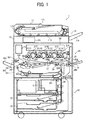
- FIG. 1 is a schematic view illustrating an image forming apparatus according to the first embodiment.
- an image forming apparatus 1 is a multifunctional peripheral having printing and copying functions, and includes a document reading portion 10, a main body 20, and a recording medium containing portion 30.
- the document reading portion 10 includes a document feeder 11 and a document reader 12.
- the document feeder 11 feeds an original set on a document tray 111 to a document ejection tray 114 along a document passage 112 via a platen 113, which is a transparent plate.
- the document reader 12 includes a reading device 121.
- the reading device 121 is arranged below the platen 113 to read the image of the original, which is fed on the platen 113, while generating image data of the original.
- the reading device 121 sends the image data to the main body 20.
- the recording medium containing portion 30 includes plural containers 31, 32 and 33, each of which contains recording medium sheets (such as paper sheets) therein, and a sheet feeding passage 34.
- the containers 31, 32 and 33 contain recording medium sheets having different sizes.
- the recording medium sheets in each of the containers 31, 32 and 33 are picked up one by one by a pickup roller 341 and fed to the main body 20.
- the image forming apparatus 1 includes a manual recording medium tray 35, which projects from a side wall of the main body 20. Recording medium sheets on the manual recording medium tray 35 are also picked up one by one by the pickup roller 341 and fed to the main body 20.
- the main body 20 forms a full color image using four toners including yellow (Y), magenta (M), cyan (C), and black (K) toners.
- the main body 20 includes image forming portions 21Y, 21M, 21C and 21K, which respectively form Y, M, C and K images, and an optical writing portion 22.
- the image forming apparatus 1 is a tandem image forming apparatus in which the four image forming portions 21Y, 21M, 21C and 21K are arranged side by side.
- the image forming portions 21Y, 21M, 21C and 21K include photoconductor drums 211Y, 211 M, 211C and 211K, respectively, each of which rotates counterclockwise.
- the optical writing portion 22 irradiates peripheral surfaces of the photoconductor drums 211Y, 211M, 211C and 211K with light to form electrostatic latent images on the photoconductor drums.
- the electrostatic latent images are developed with Y, M, C and K toners, resulting in formation of Y, M, C and K toner images on the photoconductor drums 211Y, 211M, 211C and 211K, respectively.
- the main body 20 includes a controller 23 to control operations of constituent elements of the image forming apparatus 1.
- the controller 23 receives the image data sent from the document reading portion 10, and image data generated and sent by a peripheral such as computers. Under control of the controller 23 based on the image data, the optical writing portion 22 irradiates the photoconductor drums 211Y, 211M, 211C and 211K to form electrostatic latent images thereon, and the image forming portions 21Y, 21M, 21C and 21K form Y, M, C and K toner images on the respective photoconductor drums.
- the main body 20 also includes primary transfer devices 24Y, 24M, 24C and 24K, an intermediate transfer belt 25, a pair of registration rollers 26, a secondary transfer device 27, a fixing device 28 and a sheet feeding passage 29.
- the intermediate transfer belt 25 rotates clockwise in FIG. 1 .
- the Y, M, C and K toner images formed on the respective photoconductor drums 211Y, 211M, 211C and 211K are primarily transferred to the rotated intermediate transfer belt 25 by the primary transfer devices 24Y, 24M, 24C and 24K so as to be overlaid, thereby forming a combined color toner image on the intermediate transfer belt 25. Since the intermediate transfer belt 25 rotates, the combined color toner image thereon is then fed to the secondary transfer device 27.
- the recording medium sheet fed from the recording medium containing portion 30 or the manual recording medium tray 35 is temporarily stopped before the secondary transfer device 27 by the pair of registration rollers 26.
- the pair of registration rollers 26 timely feeds the recording medium sheet to the secondary transfer device 27 so that the combined color toner image on the intermediate transfer belt 25 is transferred to a proper position of the recording medium sheet by the secondary transfer device 27.
- the recording medium sheet bearing the combined color toner image thereon is fed to the fixing device 28 along the sheet feeding passage 29, and the combined color toner image is fixed to the recording medium sheet by the fixing device 28.
- the image forming apparatus 1 can produce a duplex copy. Whether or not a duplex copy is produced is determined according to information input from the user or a peripheral such as computers. Specifically, when information of producing a single-sided copy is input, the recording medium sheet passing through the fixing device 28 and bearing a fixed toner image on one side thereof is ejected from the main body by a sheet ejecting roller 291 so as to be stacked on a sheet ejection tray 292.
- the recording medium sheet passing through the fixing device 28 and bearing a fixed toner image on one side thereof is fed to a sheet inverting passage 293.
- the recording medium sheet passing through the sheet inverting passage 293 is inverted so that the backside thereof faces the intermediate transfer belt 25, and the recording medium sheet is then fed to the pair of registration rollers 26.
- the pair of registration rollers 26 timely feeds again the recording medium sheet to the secondary transfer device 27, and another toner image on the intermediate transfer belt 25 is transferred to the backside of the recording medium sheet, followed by fixing the toner image to the backside.
- the recording medium sheet bearing fixed toner images thereon is ejected from the main body by the sheet ejecting roller 291 so as to be stacked on the sheet ejection tray 292, resulting in formation of a duplex copy.
- the sheet sensors 294 are arranged at various positions of the sheet feeding passage 29 to detect whether the recording medium sheet passes. Specifically, the sheet sensors 294 are arranged at a position downstream from the pickup roller 341 of the manual recording medium tray 35, a position at which the recording medium sheet in the recording medium containing portion 30 is picked up, and a position upstream from the pair of registration rollers 26. In addition, the sheet sensors 294 are arranged at a position downstream from the secondary transfer device 27, positions upstream and downstream from the fixing device 28, and a position upstream from the sheet ejection roller 291. Based on the detection results of these sheet sensors 294, the controller 23 determines the position in the sheet feeding passage 29, at which the recording medium sheet jams.
- the image forming apparatus 1 has the above-mentioned configuration.
- the image forming apparatus 1 has a configuration such that a drawer unit 40 having a drawer 41 is provided in the main body. Specifically, constituent parts (hereinafter sometimes referred to as image forming members) located below the intermediate transfer belt 25 such as the pair of registration rollers 26, the secondary transfer device 27, the fixing device 28, and the sheet feeding passage 29 are mounted on the drawer 41.
- the drawer 41 is inserted into or drawn from a housing 42 of the drawer unit 40, which housing also serves as a housing of the main body 20 of the image forming apparatus 1.
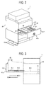
- FIG. 2 is a schematic perspective view illustrating the drawer unit of the image forming apparatus illustrated in FIG. 1 .
- FIG. 3 is a schematic side view illustrating the drawer unit.
- FIG. 4 is a perspective view illustrating in detail the drawer of the drawer unit illustrated in FIGS. 2 and 3 .
- constituent parts of the drawer 41 other than the fixing device 28 are not illustrated in FIG. 2 , and none of the constituent parts is illustrated in FIG. 3 .
- the drawer 41 of the drawer unit 40 is inserted into the housing 42 in an inserting direction D1 of from the front side (i.e., user's side) to the inner side of the image forming apparatus, and is drawn from the housing 42 in a drawing direction D2 opposite to the inserting direction D1.
- the drawer 41 includes a main body 41 a thereof including a carrier 411 to hold the constituent parts such as the fixing device 28, and a front cover 412 arranged on the front side of the carrier 411.
- the drawer main body 41 a is supported by a rail 421, which is mounted on the housing 42, in such a manner as to be movable in the directions D1 and D2.
- a drawer's-side controller 413 (drive controller) is mounted on the carrier 411 of the drawer main body 41a.
- the drawer's-side controller 413 is electrically connected with the controller 23 and a power source of the image forming apparatus 1 via a cable 414.
- the drawer's-side controller 413 controls the operations of the constituent parts such as the fixing device 28, which are mounted on the carrier 411, under control of the controller 23 of the image forming apparatus 1.
- the cable 414 is wound like a coil so that the cable is extended in the drawing direction D2 while shortened in the inserting direction D1. Therefore, when the drawer 41 is inserted or drawn, the cable 414 is shortened or extended.
- the carrier 411 of the drawer main body 41a includes a bottom plate 411a, and a rear plate 411b, which extends vertically from the rear edge of the bottom plate 411 a so as to face the front cover 412.
- a positioning pin 411 projects in the inserting direction D1 from the rear plate 411b.
- the drawer 41 further includes a rotating shaft 415, which extends from the front cover 412 to the rear plate 411b in the inserting direction D1.
- the rear end portion of the rotating shaft 415 passes through the rear plate 411b and projects from the rear plate, and a locking member 41b is mounted on the rear end portion of the rotating shaft.
- FIGS. 5A and 5B illustrate the front cover, the rotating shaft, and the locking member illustrated in FIG. 4 .
- FIG. 5A is a perspective view
- FIG. 5B is a plan view when the front cover 412 is observed from the front side.
- an operating handle 416 by which the drawer 41 is locked or by which the drawer is unlocked prior to drawing of the drawer 41, is mounted on the front cover 412.
- the operating handle 416 includes a ring-shaped frame 416a, and a gripper 416b located inside the frame 416a while extending in the diameter direction of the frame.
- the operating handle 416 is rotatable in an operating direction D3 (i.e., counterclockwise) when the operating handle is observed from the front side.
- the operating handle 416 is connected with the front end of the rotating shaft 415, on the rear end of which the locking member 41b is mounted. Therefore, when the operating handle 416 is rotated in the operating direction D3, the rotating shaft 415 and the locking member 41b are also rotated in the direction D3.
- a lock mark 416c representing a locked state of the locking member and an unlock mark 416d representing an unlocked state of the locking member are made on the front cover 412.
- the locking member 41b is engaged with the structure on the side of the housing 42, and thereby the drawer 41 is locked.
- the locking member 41b is released from the structure on the side of the housing 42 (i.e., the locking member is unlocked), and thereby the drawer 41 is unlocked.
- the operating handle 416 can be rotated only in the operating direction D3. Namely, when the drawer 41 is locked, the operating handle 416 is rotated so that the gripper 416b moves from the unlock mark 416d to the lock mark 416c in a locking direction D3-1. In this case, the locking member 41b is rotated from the unlock position to the lock position in the locking direction D3-1. In addition, when the drawer 41 is unlocked, the operating handle 416 is rotated so that the gripper 416b moves from the lock mark 416c to the unlock mark 416d in an unlocking direction D3-2. In this case, the locking member 41b is rotated from the lock position to the unlock position in the unlocking direction D3-2.
- the operating handle 416 In the unlocked state in which the gripper 416b faces the unlock mark 416d, inserting and drawing of the drawer 41 are performed. After the drawer 41 is inserted, the operating handle 416 is rotated so that the gripper 416b faces the lock mark 416c (i.e., the locked state).
- the operating handle 416 can also be used as a grip for use in inserting or drawing the drawer 41.
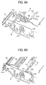
- FIGS. 6A and 6B are perspective views illustrating the rear side of the drawer and the structure of the housing, which faces the rear side of the drawer. Specifically, FIG. 6A illustrates the rear side of the drawer 41 and the structure of the housing 42 when the drawer is drawn from the housing, and FIG. 6B illustrates the rear side of the drawer 41 and the structure of the housing 42 when the drawer is inserted into the housing.
- the cable 414 extending from the drawer's-side controller 413 is wounded like a coil, and therefore the cable is extended when the drawer 41 is drawn from the housing 42 while shortened when the drawer is inserted into the housing.
- the positioning pin 411c projects from the rear plate 411b.
- the housing 42 has a positioning opening 422a on a facing plate 422 thereof facing the rear plate 411b.
- the locking member 41b is mounted on the rear end of the rotating shaft 415, which projects from the rear plate 411b of the drawer 41, and extends in a direction intersecting the inserting direction D1.
- the facing plate 422 of the housing 42 has a lock receiver 423 which is engaged with the locking member 41b when the operating handle 416 is operated so that the locking member achieves the locked state.
- the locking member 41b and the lock receiver 423 will be described in detail.
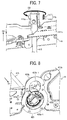
- FIG. 7 is an enlarged perspective view illustrating the locking member and a structure in the vicinity of the locking member.
- a prismatic engaging member 415a is mounted on the rear end of the rotating shaft 415, which rear end projects from the rear plate 411b of the drawer 41.
- the locking member 41b projects from the engaging member 415a in the direction intersecting the inserting direction D1.
- the locking member 41b includes a roller shaft 417 which extends in the direction intersecting the inserting direction D1, and a roller 418 rotatably mounted on the roller shaft 417. As mentioned above, the locking member 41b rotates on the rotating shaft 415 in the direction D3.
- FIG. 8 is a schematic view illustrating the lock receiver mounted on the housing. In FIG. 8 , only the lock receiver 423 is illustrated, and other parts of the housing 42 such as the facing plate 422 are not illustrated.
- the lock receiver 423 has a shape like a figure “8 ", and includes two cylinders 423a and 423b, which are connected with each other so as to extend in the vertical direction.
- the lock receiver 423 further includes a flange 423c, which is mounted on the rear ends of the cylinders 423a and 423b to fix the cylinders to the facing plate 422.
- the lower cylinder 423a has a locking member entrance 423a-1, into which the locking member 41b enters together with the prismatic engaging member 415a when the drawer 41 is inserted into the housing 42.
- the secondary transfer device 27 illustrated in FIG. 1
- the secondary transfer device 27 is located above the rotating shaft 415.
- the secondary transfer device 27 is a cylindrical member, and one end of the rotating shaft of the secondary transfer device projects from the rear plate 411b. Therefore, the upper cylinder 423b has an opening 423b-1 into which the end of the rotating shaft of the secondary transfer device 27 enters when the drawer 41 is inserted into the housing 42.
- the lock receiver 423 has a structure mounted on the locking member entrance 423a-1, wherein the structure is to be engaged with the locking member 41b.
- the operating handle 416 is in the unlocked state because the drawer 41 is just inserted into the housing 42. Therefore, the locking member 41b has the unlock position.
- the locking member 41b is also rotated in the direction D3 as illustrate in FIGS. 7 and 8 .
- FIG. 9 is a plan view illustrating the lock receiver, whose locking member entrance receives the locking member, from the rear side of the lock receiver.
- the locking member 41b has the unlock position.
- the locking member entrance 423a-1 has a locking wall 423d, with which the locking member 41b is to be engaged when the drawer 41 is locked.
- the locking member entrance 423a-1 has a pushing wall 423 e, which pushes the locking member 41b (and the drawer 41) while contacting the locking member when the locking member 41b is rotated in the unlocking direction D3-2.
- the locking member entrance 423a-1 includes a drawing wall 423f, which is located on an upstream side from the locking wall 423d relative to the locking direction D3-1 while located adjacent to the locking wall and which guides the locking member 41b to the locking wall 423d when the drawer 41 is locked, thereby drawing the drawer 41 together with the locking member 41b.
- FIG. 10 is a plan view illustrating the lock receiver, which is also illustrated in FIG. 9 .
- FIG. 11 is a perspective view illustrating the lock receiver from underneath.
- FIG. 12 is a perspective view illustrating the lock receiver from the right side.
- FIG. 13 is a perspective view illustrating the cross section of the lock receiver along a line A-A illustrated in FIG. 10 .
- FIG. 14 is a perspective view illustrating the cross section of the lock receiver along a line B-B illustrated in FIG. 10 .
- the locking member 41b When the operating handle 416 (illustrated in FIGS. 5A and 5B ) is rotated such that the gripper 416b faces the unlock mark 416d, the locking member 41b is positioned at the gap 423g. Namely, the gap 423g is the unlock position of the locking member 41b. In contrast, when the operating handle 416 is rotated such that the gripper 416b faces the lock mark 416c, the locking member 41b is positioned at a lock receiving portion 423d-1, which is part of the locking wall 423d and which is higher in the inserting direction D1 than the other portions of the locking wall 423d. The lock receiving portion 423d-1 is the lock position of the locking member 41b.
- the gripper 416b of the operating handle 416 is positioned so as to face the unlock mark 416d, and the drawer 41 is inserted while the locking member 41b maintains the unlock position.
- the locking member 41b moves in the inserting direction D1 and enters into the locking member entrance 423a-1 of the lock receiver 423.
- the operating handle 416 is rotated in the locking direction D3-1 so that the gripper 416b faces the lock mark 416c and the locking member 41b is also rotated in the locking direction D3-1.
- the lock receiving portion 423d-1 of the locking wall 423d is located in front of the locking member 41b, which has the lock position, relative to the drawing direction D2, and therefore the locking member 41b is engaged with the lock receiving portion 423d-1.
- the other portion of the locking wall 423d is a locking portion 423d-2, which is lower in level than the lock receiving portion 423d-1.
- the locking portion 423d-2 is also located in front of the locking member 41b relative to the drawing direction D2.
- the operating handle 416 is rotated such that the gripper 416b faces the unlock mark 416d, and thereby the locking member 41b is rotated in the unlocking direction D3-2 so that the locking member 41b has the unlock position.
- the pushing wall 423e is located in front of the locking wall 423d relative to the inserting direction D1, and is a wall slanting in the drawing direction D2 relative to the unlocking direction D3-2. Therefore, when the locking member 41b is rotated in the unlocking direction D3-2, the locking member 41b is released from the locking portion 423d-2 of the locking wall 423d, and then contacts the pushing wall 423e. When the locking member 41b is further rotated in the unlocking direction D3-2, the locking member 41b is pushed in the drawing direction D2 by the slanting pushing wall 423e.
- the drawing wall 423f which is slanting in the inserting direction D1 relative to the locking direction D3-1, is located adjacent to the locking wall 423d while located on an upstream side from the locking wall relative to the locking direction D3-1.
- FIG. 15 is a schematic view illustrating how the locking member illustrated in FIG. 10 achieves the lock position from the unlock position to lock the drawer, and how the locking member achieves the unlock position from the lock position to unlock the drawer.
- the rotation angle (in units of degree) of the lock member 41b is plotted on the horizontal axis, wherein the rotation angle is 0° at the unlock position, and the position of the locking member 41b relative to the inserting direction D1 is plotted on the vertical axis, wherein the locking member located at an anterior position in the inserting direction D1 is plotted on an upper position of the vertical axis, and the locking member located at an anterior position in the drawing direction D2 is plotted on a lower position of the vertical axis.
- the locking member 41b When the locking member 41b is rotated from the unlock position to the lock position in the locking direction D3-1, the locking member 41b is guided to the lock receiving portion 423d-1, which is higher in level than the drawing wall 423f, along the slanting drawing wall. In this case, the locking member 41b is drawn in the inserting direction D1.
- the locking member 41b When the locking member 41b is rotated from the lock position to the unlock position in the unlocking direction D3-2, the locking member 41b is contacted with the pushing wall 423e after passing the locking portion 423d-2, which is lower in level than the lock receiving portion 423d-1, while contacting the locking portion.
- the locking member 41b When the locking member 41b is further rotated in the unlocking direction D3-2, the locking member 41b is pushed in the direction D2 by the pushing wall 423e.
- the positioning pin 411c is inserted into the positioning opening 422a.
- the drawer 41 is electrically connected with parts on the side of the housing 42 using a connector (connector connection) as well as the cable 414 mentioned above.
- a connector connector connection
- the drawer 41 is inserted into the housing 42 and is locked, such a connector achieves an engaging state. Therefore, in the early stage of the operation of drawing the drawer 41, the operation has to be performed while encountering the resistance forces such as forces needed for extraction of the positioning pin 411c from the positioning hole 422a, and cancelling of the connector connection.
- the drawer 41 when the unlocking operation is performed prior to drawing of the drawer 41, the drawer 41 is pushed in the drawing direction D2. Therefore, the positioning pin 411 is extracted from the positioning hole 422a to some extent, and in addition cancelling of the connector connection is also performed to some extent. Therefore, the forces needed for extraction of the positioning pin and cancelling of the connector connection can be decreased in the early stage of the operation of drawing the drawer 41. Namely, the force needed for drawing the drawer 41 can be decreased.
- the drawing wall 423f is located on an upstream side relative to the locking direction D3-1 while being adjacent to the locking wall 423d.
- the locking member 41b is rotated in the locking direction D3-1 in the locking operation performed after the drawer 41 is inserted, the locking member is contacted with the drawing wall 423f.
- the drawer 41 is drawn in the inserting direction D1. Even when the positioning pin 411 c is insufficiently inserted into the positioning hole 422a or the connector connection is insufficiently performed, the drawer 41 is drawn in the inserting direction D1 by this locking operation, and thereby the positioning pin 411c is sufficiently inserted into the positioning hole 422a or the connector connection is sufficiently performed.
- the locking member 41b is mounted on the drawer 41, and the pushing wall 423e is mounted on the housing 42, Since the inner space of the housing 42 is occupied by the drawer 41, the space has no room. Therefore, the locking member 41b, which has the rotating shaft 415 requiring a space, is mounted on the drawer 41, which has a relatively wide space compared to the housing 42, and the pushing wall 423e, which requires little space, is formed on the housing.
- the drawer unit 40 of this embodiment effectively uses the inner space thereof.
- the locking wall 423d is located in front of the locking member 41b, which has the lock position, relative to the drawing direction D2.
- the pushing wall 423e is located in front of the locking wall 423d relative to the inserting direction D1 while slanting in the drawing direction D2 relative to the unlocking direction D3-2. Therefore, when the locking member 41b is rotated in the unlocking direction D3-2, the locking member 41b can smoothly move along the slanting pushing wall 423e, resulting in reduction of resistance of the locking member 41b to rotation in the unlocking direction D3-2.
- the drawing wall 423f is a wall, which is slanting in the inserting direction D1 relative to the locking direction D3-1 and which leads to the locking wall 423d. Therefore, when the locking member 41b is rotated in the locking direction D3-1, the locking member can smoothly move along the slanting drawing wall 423f, resulting in reduction of resistance of the locking member 41b to rotation in the locking direction D3-1.
- the locking member 41b is equipped with the roller shaft 417 and the roller 418. Therefore, when the locking member 41b moves toward the locking wall 423d while contacting the drawing wall 423f in the locking operation, or when the locking member 41b moves toward the gap 423g while contacting the pushing wall 423e in the unlocking operation, contact resistance of the locking member 41b can be reduced when the locking member is contacted with the walls. As a result, the operating handle 416 can be smoothly operated in the locking operation and the unlocking operation.
- the second embodiment is similar to the first embodiment except for the structure of the lock receiver 423. Therefore, the second embodiment will be described while paying attention to the difference, and description of the common points (such as configuration of the image forming apparatus and the drawer unit) is omitted.
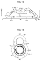
- FIG. 16 is a plan view illustrating the lock receiver of the drawer unit of the second embodiment.
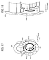
- FIG. 17 is a perspective view illustrating the lock receiver when the lock receiver is observed from the right side thereof.
- FIG. 18 is a perspective view illustrating the cross section of the lock receiver along a line C-C illustrated in FIG. 16 .
- FIG. 19 is a schematic view illustrating how the locking member illustrated in FIG. 16 achieves the lock position from the unlock position to lock the drawer, and how the locking member achieves the unlock position from the lock position to unlock the drawer.
- the constituent parts of the lock receiver and the arrows have the same reference numbers of the constituent parts of the lock receiver illustrated in FIGS. 10-15 . Therefore, description of the constituent parts and the arrows will be omitted hereinafter.
- the second embodiment will be described by reference to the constituent parts illustrated in FIGS. 1-15 , which are used for description of the first embodiment.
- a lock receiver 500 of the drawer unit of the second embodiment does not have a slanting wall such as the drawing wall 423f of the lock receiver 423 of the drawer unit of the first embodiment.
- the lock receiver 500 includes a supporting wall 501, which is the unlock position and which is an ark-like flat wall extending from the gap 423g to a position just before the pushing wall 423e in the locking direction D3-1 and the unlocking direction D3-2.
- the locking member 41b When the drawer 41 is inserted in the inserting direction D1, the locking member 41b enters into the locking member entrance 423a-1.
- the locking member 41b When the locking member 41b is rotated from the unlock position to the lock position in the locking direction D3-1, the locking member 41b initially runs upon the flat supporting wall 501, and then moves on the supporting wall until the gripper 416b faces the lock mark 416c.
- the locking member 41b is rotated from the lock position to the unlock position in the unlocking direction D3-2, the locking member 41b is contacted with the pushing wall 423e after moving on the supporting wall 501.
- the locking member 41b When the locking member 41b is further rotated in the unlocking direction D3-2, the locking member is pushed in the drawing direction D2 by the pushing wall 423e.
- the locking member 41b runs upon the flat supporting wall 501 in the initial stage of the locking operation. Therefore, resistance that the locking operation encounters is relatively large compared to that in the first embodiment in which the locking member 41b moves along the slanting drawing wall 423f. However, even in this second embodiment, a force of drawing the drawer 41 in the inserting direction D1 is generated when the locking member 41b runs upon the flat supporting wall 501. Therefore, similarly to the first embodiment, by performing the locking operation after the drawer 41 is inserted, the positioning pin 411c can be perfectly inserted into the positioning hole 422a or the connector connection can be perfectly performed.
- the locking member 41b and the drawer 41 can be pushed by the pushing wall 423e in this second embodiment, and therefore the force needed for drawing the drawer 41 can be reduced.
- the third embodiment will be described.
- the difference between the third embodiment and the first embodiment is that the locking and unlocking operations are performed by motor driving in the third embodiment while the operating handle 416 is used therefor in the first embodiment. Since the structures of the image forming apparatus and the drawer unit are the same as those in the first embodiment, the third embodiment will be described while paying attention to the difference, and description of the common points is omitted.
- FIG. 20 is a schematic view illustrating part of the drawer of the third embodiment, in which locking and unlocking are performed by motor driving.
- the constituent parts similar to the constituent parts used for the first embodiment have the same reference numbers of the constituent parts used for the first embodiment. Therefore, description of the constituent parts will be omitted hereinafter. The same is true for description of the third embodiment by reference to FIGS. 21 and 22 .
- the third embodiment will be described by reference to the constituent parts illustrated in FIGS. 1-15 , which are used for description of the first embodiment.
- a drive member 600 to drive the rotating shaft 415 of the locking member 41b is arranged between the front cover 412 of the drawer 41 and the front plate 411 d of the carrier 411 (illustrated in FIG. 5 ).
- the drive member 600 includes a motor 601, and a group of gears 602 to transmit the rotary drive force of the motor to the rotating shaft 415.
- the operation of the drive member 600 is controlled as mentioned below by the drawer's-side controller 413 (illustrated in FIG. 3 ).
- the drawer's-side controller 413 controls in such a manner that when the drawer 41 is inserted, the drive member 600 rotates the locking member 41b from the unlock position to the lock position.
- the drawer's-side controller 413 controls in such a manner that when the drawer 41 is drawn, the drive member 600 rotates the locking member 41b from the lock position to the unlock position prior to drawing of the drawer 41.
- the drawer's-side controller 413 serves as a drive controller.
- rotary drive of the locking member 41b from the unlock position to the lock position performed when the drawer 41 is inserted is started under control of the drawer's-side controller 413, wherein the trigger of starting rotary drive is detection of insertion of the drawer 41 using such a sensor as mentioned below.
- FIG. 21 illustrates a sensor to detect insertion of the drawer.
- a set sensor 610 to detect insertion of the drawer 41 include an inserting fin 611, and a photosensor 612 mounted on the facing plate 422 of the housing 42.
- the photosensor 612 has a configuration such that a light emitting element and a light receiving element are arranged in the vertical direction while having a space therebetween. When the drawer 41 is not inserted, light emitted by the light emitting element is detected by the light receiving element, and therefore the photosensor 612 is in an ON state.
- the inserting fin 611 is inserted into the space between the light emitting element and the light receiving element of the photosensor 612 after passing through a through-hole on the facing plate 422 of the housing 42.
- the inserting fin 611 intercepts light emitted by the light emitting element, and therefore the photosensor 612 achieves an OFF state.
- the set sensor 610 detects insertion of the drawer 41 when the photosensor 612 achieves the OFF state.
- the drawer's-side controller 413 controls the drive member 600 such that the rotating shaft 415 (i.e., the locking member 41b) starts to rotate in the locking direction D3-1.
- the drawer's-side controller 413 controls the drive member 600 such that the rotating shaft 415 (i.e., the locking member 41b) starts to rotate in the unlocking direction D3-2, wherein the trigger thereof is the following phenomenon.
- a release button hereinafter unlock button
- pushing the unlock button prior to drawing of the drawer 41 triggers the drawer's-side controller 413 to control the drive member 600 such that the rotating shaft 415 (i.e., the locking member 41b) starts to rotate in the unlocking direction D3-2.
- the drawer unit of this embodiment includes a sensor to detect that the locking member 41b reaches the lock position from the unlock position and that the locking member reaches the unlock position from the lock position.
- the drawer's-side controller 413 controls the operation of the drive member 600 based on the detection results of the sensor.
- the sensor is the following.
- FIG. 22 illustrates a lock sensor 620 to detect that the locking member 41b reaches the lock position from the unlock position and that the locking member reaches the unlock position from the lock position.
- the lock sensor 620 includes an inserting fin 621, which is mounted on the rotating shaft 415 and which is located on a downstream (rear) side from the rear plate 411b relative to the inserting direction D1.
- the inserting fin 621 is a disk, which is perpendicular to the rotating shaft 415 and which has a notch (i.e., part of the disk is cut).
- the lock sensor 620 includes a photosensor 622 which is mounted on the rear side of the rear plate 411b.
- the photosensor 622 has a configuration such that a light emitting element 622a and a light receiving element 622b are arranged in the inserting direction D 1 while separated from each other.
- the photosensor 622 achieves an OFF state.
- the notch of the inserting fin 621 is located between the light emitting element 622a and the light receiving element 622b and the inserting fin does not intercept light emitted by the light emitting element 622a, the photosensor 622 achieves an ON state.
- the inserting fin 621 is set such that when the locking member 41b is rotated in the locking direction D3-1 and has the lock position, a first edge 621a of the notch of the inserting fin 621 reaches the space between the light emitting element 622a and the light receiving element 622b. Namely, during the locking member 41b is rotated in the locking direction D3-1, the photosensor 622 is in the ON state, and when the locking member 41b has the lock position, the photosensor 622 achieves the OFF state. Thus, the lock sensor 620 detects that the locking member 41b reaches the lock position from the unlock position when the photosensor 622 changes the state thereof from the ON state to the OFF state.
- the inserting fin 621 is set such that when the locking member 41b is rotated in the unlocking direction D3-2 and has the unlock position, a second edge 621b of the notch of the inserting fin 621 reaches the space between the light emitting element 622a and the light receiving element 622b. Namely, during the locking member 41b is rotated in the unlocking direction D3-2, the photosensor 622 is in the OFF state, and when the locking member 41b has the unlock position, the photosensor 622 achieves the ON state. Thus, the lock sensor 620 detects that the locking member 41b reaches the unlock position from the lock position when the photosensor 622 changes the state thereof from the OFF state to the ON state.
- the drawer's-side controller 413 controls the drive member 600 to drive the locking member 41b to start rotating in the locking direction D3-1, wherein the trigger thereof is detection of insertion of the drawer 41.
- the drawer's-side controller 413 controls the drive member 600 to stop the rotary drive, resulting in completion of locking of the drawer 41.
- the drawer's-side controller 413 controls the drive member 600 to drive the locking member 41b to start rotating in the unlocking direction D3-2, wherein the trigger thereof is push of unlock button.
- the drawer's-side controller 413 controls the drive member 600 to stop the rotary drive, resulting in completion of unlocking of the drawer 41.
- the drawer unit of the third embodiment includes the drive member 600 to rotate the locking member 41b, and the drawer's-side controller 413 to control the drive member 600. Therefore, locking and unlocking can be automatically performed, and thereby burden on the user can be further reduced.
- the drawer unit of the third embodiment includes the lock sensor 620 to detect that the locking member 41b reaches the lock position from the unlock position and that the locking member reaches the unlock position from the lock position.
- the drawer's-side controller 413 controls the operation of the drive member 600 based on the detection results of the lock sensor 620. Specifically, the drawer's-side controller 413 controls the drive member 600 to stop rotary drive. Therefore, whether the locking member 41b reaches the lock position or the unlock position can be detected precisely, and therefore locking or unlocking of the drawer 41 can be secured.
- unlock of the drawer 41 is controlled by the drawer's-side controller 413. Therefore, when a recording medium sheet is jammed while bridging between the inside and the outside of the drawer 41, it becomes possible to control the drive member 600 not to perform rotary drive until the jammed recording medium sheet is removed or moved to the inside or outside of the drawer 41. By performing such a control, unlocking of the drawer 41 is not performed until the jammed recording medium sheet is removed or moved to the inside or outside of the drawer 41. Therefore, occurrence of the problem in that the jammed recording medium sheet is deformed or broken by drawing the drawer 41 can be prevented.
- the sheet sensors 294 are arranged at several positions of the image forming apparatus 1. For example, when the jammed recording medium sheet is detected by the sheet sensor 294 located on the downstream side from the pickup roller 341 of the manual recording medium tray 35, the jammed recording medium sheet is deformed or broken if the drawer 41 is drawn. The same is true for the jammed recording medium sheet detected by the sheet sensor 294 located above the sheet feeding passage 34, and for the jammed recording medium sheet detected by the sheet sensor 294 located on the upstream side from the sheet ejecting roller 291. Since the control mentioned above is performed in this embodiment, occurrence of the problem in that the jammed recording medium sheet is deformed or broken by drawing the drawer 41 can be prevented.
- the fourth embodiment of this disclosure will be described.
- locking and unlocking of the drawer 41 are performed by motor drive similar to the third embodiment, but the locking and unlocking method is different from that in the third embodiment.
- the configuration of the image forming apparatus and the drawer unit of the fourth embodiment is the same as that of the third (or first) embodiment. Therefore, hereinafter the fourth embodiment will be described while paying attention to the difference between the fourth embodiment and the third embodiment, and description of the common points is omitted.
- the fourth embodiment will be described by reference to the constituent parts illustrated in FIGS. 1-22 , which are used for the description of the first, second and third embodiments.
- the rotation direction of the locking member 41b in the unlocking operation performed when the recording medium sheet is jammed is different from the rotation direction of the locking member in the unlocking operation performed in other cases.
- jamming of the recording medium sheet is detected by the following method in the image forming apparatus 1.
- the sheet sensors 294 are arranged at several positions of the image forming apparatus 1.
- the recording medium sheet passes the sheet sensors 294 at predetermined times.
- the sheet sensor 294 located on the downstream side from the jamming point does not detect the recording medium sheet at the predetermined time.
- the controller 23 recognizes (detects) jamming of the recording medium sheet, and notifies the drawer 41 of the jamming of the recording medium sheet.
- the unlock button is mounted on the drawer 41 similarly to the third embodiment.
- the button pushing operation triggers rotation of the locking member 41b for unlocking.
- rotation of the locking member 41b is automatically started under the below-mentioned control without performing the operation instructed by pushing the unlock button.
- the rotation direction of the locking member 41b in the case in which there is a notification of jamming before the unlock button is pushed is different from the rotation direction of the locking member 41b in the case in which there is no notification of jamming before the unlock button is pushed. The difference will be described below.
- FIG. 23 is a schematic view illustrating a rotation direction of the locking member of the drawer unit according to the fourth embodiment of this disclosure, wherein the locking member rotates to achieve the unlock position in a case of jamming of the recording medium sheet, and a rotation direction of the locking member, wherein the locking member rotates to achieve the unlock position in other cases.
- FIG. 24 is a schematic view illustrating how the locking member illustrated in FIG. 23 achieves the unlock position when rotating in the two rotation directions.
- the constituent parts and arrows have the same reference numbers of the constituent parts and arrows, which are used for the first to third embodiments and which are illustrated in FIGS. 1-22 . Therefore, description of the constituent parts will be omitted hereinafter. The same is true for description of the fourth embodiment by reference to FIGS. 25-28 .
- the lock receiver 500 having the flat supporting wall 501 which is described above in the second embodiment by reference to FIGS. 16-19 , is used for the fourth embodiment.
- the rotating shaft 415 of the locking member 41b can also be rotated in a second unlocking direction D3-3, which is opposite to the locking direction D3-1 and the unlocking direction D3-2.
- the locking member 41b when the locking member 41b is rotated from the lock position on the supporting wall 501 to the unlock position (i.e., the gap 423g) via the pushing wall 423e in the unlocking direction D3-2, the locking member 41b is rotated at a first angle ⁇ 1.
- the locking member 41b is rotated from the lock position to the unlock position in the second unlocking direction D3-3, the locking member 41b is rotated at a second angle ⁇ 2, which is smaller than the first angle ⁇ 1.
- the controller 23 of the image forming apparatus 1 notifies a drawer's-side controller 701 of detection of jamming.
- the drawer's-side controller 701 receives the notification before the unlock button is pushed, the drawer's-side controller 701 controls the drive member 600 to drive the locking member 41b to rotate in the unlocking direction D3-2 so as to have the unlock position.
- the drawer's-side controller 701 controls the drive member 600 to drive the locking member to rotate in the second unlocking direction D3-3 so as to have the unlock position.
- the locking member 41b is rotated in the unlocking direction D3-2, so that the locking member is pushed by the pushing wall 423e and thereby the drawer 41 is pushed in the unlocking direction D2.
- the locking member 41b when jamming of the recording medium sheet does not occur, the locking member 41b is rotated in the second unlocking direction D3-3 without passing the pushing wall 423e to achieve the unlock position.
- the second rotation angle ⁇ 2 in the second unlocking direction D3-3 is smaller than the first angle ⁇ 1 in the unlocking direction D3-2, the unlocking operation can be performed in a short time.
- the position of the locking member 41b is not changed in the drawing direction D2. Therefore, when the drawer 41 is not drawn and is locked again, the locking member 41b can be smoothly moved to the supporting wall 501. Therefore, the locking operation can be performed again while reducing the burden on the locking member 41b and the drive member 600.
- the unlocking operation is automatically performed under the below-mentioned control of the drawer's-side controller 701 without performing the operation using the unlock button.
- the jamming is resolved by performing plural processes including a process of drawing the drawer 41.
- the plural processes include a process in which, when the recording medium sheet is jammed while bridging between the inside and the outside of the drawer 41, the recording medium sheet is moved to the inside or outside of the drawer prior to drawing of the drawer 41.
- a process in which, when the recording medium sheet is jammed at a location other than the drawer 41, the jammed recording medium sheet is removed from the image forming apparatus 1 prior to drawing of the drawer 41 is also included in the plural processes.
- the plural processes mentioned above are performed under control of the controller 23 of the image forming apparatus 1.
- the controller 23 decides that it is time to draw the drawer 41
- the controller 23 notifies the drawer's-side controller 701 of the decision.
- the drawer's-side controller 413 controls the drive member 600 to drive the locking member 41b to start rotating, wherein the trigger thereof is the notification from the controller 23.
- the locking member 41b is rotated in the unlocking direction D3-2 via the pushing wall 423, and therefore the drawer 41 is pushed in the drawing direction D2 along with unlocking, thereby reducing resistance of the drawer 41 to drawing.
- the drawer 41 is pushed at this time, the user is notified that it is time to perform a process of drawing the drawer 41, followed by a process of removing the recording medium sheet from the drawer 41.
- a position sensor to detect two positions (mentioned below) of the drawer 41 in the inserting direction D 1 and the drawing direction D2 is provided.
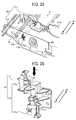
- FIG. 25 is a schematic view illustrating a position sensor 710 to detect two positions of the drawer 41 in the inserting direction D 1 and the drawing direction D2.
- the position sensor 710 includes an inserting fin unit 711, which projects from the rear plate 411b of the drawer 41 in the inserting direction D1, and a photosensor unit 712 mounted on the facing plate 422 of the housing 42.
- the inserting fin unit 711 includes a first inserting fin 711a and a second inserting fin 711b, which are arranged so as to be apart from each other in the vertical direction.
- the first inserting fin 711a is located below the second inserting fin 711b.
- the photosensor unit 712 includes a first photosensor 712a and a second photosensor 712b, which correspond to the first inserting fin 711a and the second inserting fin 711b, respectively.
- Each of the first and second photosensors 712a and 712b has a light emitting element and a light receiving element, which are arranged in the vertical direction while separated from each other. When the drawer 41 is not inserted, light emitted by the light emitting element is received by the light receiving element, and therefore the photosensor achieves the ON state.
- the first inserting fin 711 a and the second inserting fin 711b are respectively inserted into the gap between the light emitting element and the light receiving element of the first photosensor 712a and the gap between the light emitting element and the light receiving element of the second photosensor 712b.
- the light receiving elements do not receive light emitted by the light emitting elements, each of the first and second photosensors 712a and 712b achieves the OFF state.
- FIG. 26 illustrates the position sensor in which the first inserting fin and the second inserting fin are respectively inserted into the gap between the light emitting element and the light receiving element of the first photosensor and the gap between the light emitting element and the light receiving element of the second photosensor.
- FIG. 27 is a plan view illustrating the position sensor illustrated in FIG. 26 from a direction V1 illustrated in FIG. 26 .
- the first photosensor 712a and the second photosensor 712b are located at different positions in the inserting direction D 1 and the drawing direction D2. Specifically, the first photosensor 712a is located in front of the second photosensor 712b in the inserting direction D1, and the second photosensor 712b is located in front of the first photosensor 712a in the drawing direction D2. In this regard, the distance between the first and second photosensors is L1 as illustrated in FIG. 27 .
- the photosensor 710 When the drawer 41 is inserted in the inserting direction D 1 and the drawer reaches a distant position before the predetermined perfect insertion position at the distance L1 in the inserting direction D1, the photosensor 710 performs the following detection. Specifically, in this stage, the second inserting fin 711b, which is located on the upper side, is inserted into the gap between the light emitting element and the light receiving element of the second photosensor 712b, which is also located on the upper side. As a result, the second photosensor 712b achieves the OFF state, and the position sensor 710 detects that the drawer 41 reaches the distant position.
- the first inserting fin 711 a which is located on the lower side, is inserted into the gap between the light emitting element and the light receiving element of the first photosensor 712a, which is also located on the lower side.
- the first photosensor 712a achieves the OFF state.
- the second photosensor 712b maintains the OFF state.
- the position sensor 710 detects that the drawer 41 is completely inserted to the perfect insertion position.
- the first inserting fin 711a is drawn from the gap between the light emitting element and the light receiving element of the first photosensor 712a, and thereby the first photosensor 712a achieves the ON state.
- the second inserting fin 711b passes through the gap between the light emitting element and the light receiving element of the second photosensor 712b, the second photosensor 712b achieves the ON state while the first photosensor 712a maintains the ON state.
- the position sensor 710 detects that the drawer 41 is drawn to the distant position when the second photosensor 712b achieves the ON state.
- the first photosensor 712a serves as a first sensor which detects that the drawer 41 is located at the perfect insertion position
- the second photosensor 712b serves as a second sensor which detects that the drawer 41 is located at the distant position.
- the drawer's-side controller 701 notifies the controller 23 of the image forming apparatus 1 of the detection results of the first and second photosensors 712a and 712b.
- a guide image is displayed in the operation panel of the image forming apparatus.
- the guide image includes guidance on the plural processes of resolving jamming of the recording medium sheet. Specifically, regarding the process of drawing the drawer 41 and the subsequent process of removing the jammed recording medium sheet, the following guide images are displayed.
- FIG. 28A and 28B are guide images which are respectively used for the process of drawing the drawer and the subsequent process of removing the recoding medium sheet from the drawer. Specifically, FIG. 28A illustrates a guide image GI-1 for use in the process of drawing the drawer, and FIG. 28B illustrates another guide image GI-2 for use in the process of removing the recording medium sheet.
- the guide image GI-1 illustrated in FIG. 28A is an animation image including four images which gradually change from left to right and which are used for illustrating the way to draw the drawer 41.
- the guide image GI-2 illustrated in FIG. 28B illustrates the sheet removing position, from which the recording medium sheet jammed in this time is removed, among plural sheet removing positions present in the drawer 41. In this regard, among the plural sheet removing positions, the sheet removing position to be used for this time is illustrated.
- the guide image GI-2 changes in every removal of the recording medium sheet.
- the plural sheet removing positions are guided one by one.
- the distance L1 illustrated in FIG. 27 is set to a length longer than the length by which the drawer 41 is pushed in the pushing operation mentioned above. Therefore, after the locking member 41b is rotated and thereby the drawer 41 is pushed, the first photosensor 712a achieves the ON state, but the second photosensor 712b maintains the OFF state.
- the guide image GI-1 illustrated in FIG. 28A is displayed until the user further draws the drawer 41 to an extent such that the second photosensor 712b achieves the ON state.
- the guide image GI-1 which is the animation image is repeatedly displayed.
- the guide image GI-1 is switched to the guide image GI-2 illustrated in FIG. 28B . This switching is performed under control of the controller 23 when the controller is notified of the detection results of the first photosensor 712a and the second photosensor 712b.
- the drawer unit of this embodiment includes the first photosensor 712a and the second photosensor 712b to detect two positions of the drawer 41, and therefore the guide images can be switched depending on the progress of the jamming resolving processes of the user. Therefore, the user can perform the jamming resolving processes (i.e., drawing the drawer 41 and removing the jammed recording medium sheet) while watching the guide images.
- the four embodiments mentioned above relate to a drawer unit 40 installed in an image forming apparatus.
- the drawer unit of this disclosure is not limited thereto.
- the drawer unit can be installed in a desk or a cabinet.
- the configuration of the drawer unit of this disclosure is not particularly limited as long as the drawer unit includes a drawer and a housing.
- the locking member 41b is mounted on the drawer 41, and the locking wall 423 and the pushing wall 423e are formed on the housing 42.
- the drawer unit of this disclosure is not limited thereto.
- the drawer unit can have a configuration such that the locking member is mounted on the housing, and the locking wall and the pushing wall are formed on the drawer.
- the inner space of the drawer unit can be effectively used when the drawer unit has a configuration such that the locking member is mounted on the drawer, and the locking wall and the pushing wall are formed on the housing.
- the drawer unit having a configuration such that the locking member is mounted on the housing, and the locking wall and the pushing wall are formed on the drawer, the positional relationship between the locking wall and the pushing wall, and the slanting direction of the pushing wall are opposite to those in the drawer unit mentioned above in the four embodiments.
- an image forming apparatus which is a multifunctional periphery having a color printing function and a copying function, is exemplified as the image forming apparatus of this disclosure.
- the image forming apparatus of this disclosure is not limited thereto.
- the image forming apparatus of this disclosure can be a printer, a copier, a facsimile or the like, which produces monochromatic images or color images.
- the drawer unit of this disclosure can be used for image forming apparatus and can be drawn by a reduced drawing force.
Landscapes
- Physics & Mathematics (AREA)
- General Physics & Mathematics (AREA)
- Engineering & Computer Science (AREA)
- Mechanical Engineering (AREA)
- Electrophotography Configuration And Component (AREA)
Abstract
Description
- This patent application is based on and claims priority pursuant to 35 U.S.C. §119 to Japanese Patent Applications Nos.
2015-016405 2015-178430, filed on January 30, 2015 - This disclosure relates to a drawer unit, and to an image forming apparatus using the drawer unit.
- There is an electrophotographic image forming apparatus, which is disclosed, for example, in
JP-2014-134753-A - In such an image forming apparatus, when the force (hereinafter referred to as drawing force) needed for drawing the drawer from the housing of the image forming apparatus is large, the drawing operation is a burden to a powerless user.
JP-2012-245311-A - In addition,
JP-2004-154322-A - Since the drawer unit disclosed in
JP-2012-245311-A - In addition, the drawer disclosed in
JP-2004-154322-A - Thus, there is no drawer which can be used for image forming apparatus and which has such a configuration as to reduce the drawing force needed for drawing the drawer.
- The object of this disclosure is to provide a drawer unit, which can be used for image forming apparatus and which has such a configuration as to reduce the drawing force.
- As an aspect of this disclosure, a drawer unit is provided which includes a housing, and a drawer which is inserted into the housing in an inserting direction and is drawn from the housing in a drawing direction opposite to the inserting direction, a locking member which is mounted on the housing or the drawer, and a locking wall and a pushing wall which are mounted on the other of the housing and the drawer. The locking member extends in a direction intersecting the inserting direction, and is rotatable on a rotating shaft extending in the inserting direction. When the drawer is inserted into the housing, the locking member rotates from a predetermined unlock position to a predetermined lock position in a locking direction. In addition, the locking member rotates from the lock position to the unlock position in an unlocking direction prior to drawing of the drawer. When the locking member is in the lock position, the locking member is engaged with the locking wall. When the locking member is rotated in the unlocking direction, the locking member is contacted with the pushing wall, and the pushing wall pushes the drawer in the drawing direction as the locking member rotates in the unlocking direction.
- As another aspect of this disclosure, an image forming apparatus is provided which includes image forming members to form and fix a toner image on a recording medium sheet, and the above-mentioned drawer unit, wherein one or more of the image forming members are mounted on the drawer unit.
- The aforementioned and other aspects, features and advantages will become apparent upon consideration of the following description of the preferred embodiments taken in conjunction with the accompanying drawings.
-
-
FIG. 1 is a schematic view illustrating an image forming apparatus according to an embodiment of this disclosure; -
FIG. 2 is a perspective view illustrating a drawer unit of the image forming apparatus illustrated inFIG. 1 ; -
FIG. 3 is a side view of the drawer unit illustrated inFIG. 2 ; -
FIG. 4 is a perspective view illustrating in detail the drawer illustrated inFIGS. 2 and 3 ; -
FIG. 5A and 5B are schematic views illustrating a front cover, a rotating shaft, and a locking member of the drawer illustrated inFIG. 4 ; -
FIG. 6A and 6B are schematic views illustrating the rear side of the drawer and the rear side of a housing facing the rear side of the drawer; -
FIG. 7 is an enlarged view illustrating the locking member and the vicinity thereof; -
FIG. 8 is a schematic view illustrating a lock receiver mounted on a housing; -
FIG. 9 is a plan view illustrating the rear side of the lock receiver, which receives the locking member entering into an entrance of the lock receiver; -
FIG. 10 is a plan view illustrating the lock receiver illustrated inFIG. 9 ; -
FIG. 11 is a perspective view illustrating the lock receiver from underneath; -
FIG. 12 is a perspective view illustrating the lock receiver from the right side; -
FIG. 13 is a perspective view illustrating the cross section of the lock receiver along a line A-A illustrated inFIG. 10 ; -
FIG. 14 is a perspective view illustrating the cross section of the lock receiver along a line B-B illustrated inFIG. 10 ; -
FIG. 15 is a schematic view illustrating how the locking member illustrated inFIG. 10 achieves a lock position from an unlock position, and achieves the unlock position from the lock position; -
FIG. 16 is a plan view illustrating a lock receiver of a drawer unit according to a second embodiment of this disclosure; -
FIG. 17 is a perspective view illustrating the lock receiver illustrated inFIG. 16 from the right side; -
FIG. 18 is a perspective view illustrating the cross section of the lock receiver along a line C-C illustrated inFIG. 16 ; -
FIG. 19 is a schematic view illustrating how the locking member illustrated inFIG. 16 achieves a lock position from an unlock position, and achieves the unlock position from the lock position; -
FIG. 20 is a schematic view illustrating a drawer unit according to a third embodiment of this disclosure, in which locking and unlocking are performed by motor driving; -
FIG. 21 is a schematic view illustrating a set sensor to detect insertion of the drawer; -
FIG. 22 is a schematic view illustrating a lock sensor to detect that the locking member achieves a lock position from the unlock position and that the locking member achieves the unlock position from the lock position; -
FIG. 23 is a schematic view illustrating a rotation direction of a locking member of a drawer unit according to a fourth embodiment of this disclosure when the locking member rotates to achieve the unlock position in a case of jamming of a recording medium sheet, and a rotation direction of the locking member rotating to achieve the unlock position in other cases; -
FIG. 24 is a schematic view illustrating how the locking member illustrated inFIG. 23 achieves the unlock position when rotating in the two rotation directions; -
FIG. 25 is a schematic view illustrating a position sensor to detect the position of the drawer when the drawer is inserted in an inserting direction D1 or drawn in a drawing direction D2; -
FIG. 26 is a perspective view illustrating the position sensor whose first and second insertion fins are inserted into corresponding gaps between a light emitting element and a light receiving element of first and second photosensors; -
FIG. 27 is a plan view illustrating the position sensor illustrated inFIG. 26 from a direction indicated by an arrow V1 illustrated inFIG. 26 ; and -
FIG. 28A and 28B are images which are respectively used as an operation guide for drawing the drawer and another operation guide for removing a recoding medium sheet from the drawer. - Hereinafter, several embodiments of this disclosure will be described by reference to drawings. Initially, a first embodiment of this disclosure will be described by reference to drawings.
FIG. 1 is a schematic view illustrating an image forming apparatus according to the first embodiment. Referring toFIG. 1 , animage forming apparatus 1 is a multifunctional peripheral having printing and copying functions, and includes adocument reading portion 10, amain body 20, and a recordingmedium containing portion 30. - The
document reading portion 10 includes adocument feeder 11 and adocument reader 12. Thedocument feeder 11 feeds an original set on adocument tray 111 to adocument ejection tray 114 along adocument passage 112 via aplaten 113, which is a transparent plate. Thedocument reader 12 includes areading device 121. Thereading device 121 is arranged below theplaten 113 to read the image of the original, which is fed on theplaten 113, while generating image data of the original. Thereading device 121 sends the image data to themain body 20. - The recording
medium containing portion 30 includesplural containers sheet feeding passage 34. Thecontainers containers pickup roller 341 and fed to themain body 20. In addition, theimage forming apparatus 1 includes a manualrecording medium tray 35, which projects from a side wall of themain body 20. Recording medium sheets on the manualrecording medium tray 35 are also picked up one by one by thepickup roller 341 and fed to themain body 20. - The
main body 20 forms a full color image using four toners including yellow (Y), magenta (M), cyan (C), and black (K) toners. Themain body 20 includesimage forming portions optical writing portion 22. - The
image forming apparatus 1 is a tandem image forming apparatus in which the fourimage forming portions image forming portions photoconductor drums optical writing portion 22 irradiates peripheral surfaces of the photoconductor drums 211Y, 211M, 211C and 211K with light to form electrostatic latent images on the photoconductor drums. The electrostatic latent images are developed with Y, M, C and K toners, resulting in formation of Y, M, C and K toner images on the photoconductor drums 211Y, 211M, 211C and 211K, respectively. - The
main body 20 includes acontroller 23 to control operations of constituent elements of theimage forming apparatus 1. Thecontroller 23 receives the image data sent from thedocument reading portion 10, and image data generated and sent by a peripheral such as computers. Under control of thecontroller 23 based on the image data, theoptical writing portion 22 irradiates the photoconductor drums 211Y, 211M, 211C and 211K to form electrostatic latent images thereon, and theimage forming portions - The
main body 20 also includesprimary transfer devices intermediate transfer belt 25, a pair ofregistration rollers 26, asecondary transfer device 27, a fixingdevice 28 and asheet feeding passage 29. - The
intermediate transfer belt 25 rotates clockwise inFIG. 1 . The Y, M, C and K toner images formed on therespective photoconductor drums intermediate transfer belt 25 by theprimary transfer devices intermediate transfer belt 25. Since theintermediate transfer belt 25 rotates, the combined color toner image thereon is then fed to thesecondary transfer device 27. - The recording medium sheet fed from the recording
medium containing portion 30 or the manualrecording medium tray 35 is temporarily stopped before thesecondary transfer device 27 by the pair ofregistration rollers 26. The pair ofregistration rollers 26 timely feeds the recording medium sheet to thesecondary transfer device 27 so that the combined color toner image on theintermediate transfer belt 25 is transferred to a proper position of the recording medium sheet by thesecondary transfer device 27. The recording medium sheet bearing the combined color toner image thereon is fed to the fixingdevice 28 along thesheet feeding passage 29, and the combined color toner image is fixed to the recording medium sheet by the fixingdevice 28. - The
image forming apparatus 1 can produce a duplex copy. Whether or not a duplex copy is produced is determined according to information input from the user or a peripheral such as computers. Specifically, when information of producing a single-sided copy is input, the recording medium sheet passing through the fixingdevice 28 and bearing a fixed toner image on one side thereof is ejected from the main body by asheet ejecting roller 291 so as to be stacked on asheet ejection tray 292. - In contrast, when information of producing a duplex copy is input, the recording medium sheet passing through the fixing
device 28 and bearing a fixed toner image on one side thereof is fed to asheet inverting passage 293. The recording medium sheet passing through thesheet inverting passage 293 is inverted so that the backside thereof faces theintermediate transfer belt 25, and the recording medium sheet is then fed to the pair ofregistration rollers 26. The pair ofregistration rollers 26 timely feeds again the recording medium sheet to thesecondary transfer device 27, and another toner image on theintermediate transfer belt 25 is transferred to the backside of the recording medium sheet, followed by fixing the toner image to the backside. The recording medium sheet bearing fixed toner images thereon is ejected from the main body by thesheet ejecting roller 291 so as to be stacked on thesheet ejection tray 292, resulting in formation of a duplex copy. -
Several sheet sensor 294 are arranged at various positions of thesheet feeding passage 29 to detect whether the recording medium sheet passes. Specifically, thesheet sensors 294 are arranged at a position downstream from thepickup roller 341 of the manualrecording medium tray 35, a position at which the recording medium sheet in the recordingmedium containing portion 30 is picked up, and a position upstream from the pair ofregistration rollers 26. In addition, thesheet sensors 294 are arranged at a position downstream from thesecondary transfer device 27, positions upstream and downstream from the fixingdevice 28, and a position upstream from thesheet ejection roller 291. Based on the detection results of thesesheet sensors 294, thecontroller 23 determines the position in thesheet feeding passage 29, at which the recording medium sheet jams. - The
image forming apparatus 1 has the above-mentioned configuration. In addition, theimage forming apparatus 1 has a configuration such that adrawer unit 40 having adrawer 41 is provided in the main body. Specifically, constituent parts (hereinafter sometimes referred to as image forming members) located below theintermediate transfer belt 25 such as the pair ofregistration rollers 26, thesecondary transfer device 27, the fixingdevice 28, and thesheet feeding passage 29 are mounted on thedrawer 41. Thedrawer 41 is inserted into or drawn from ahousing 42 of thedrawer unit 40, which housing also serves as a housing of themain body 20 of theimage forming apparatus 1. -
FIG. 2 is a schematic perspective view illustrating the drawer unit of the image forming apparatus illustrated inFIG. 1 .FIG. 3 is a schematic side view illustrating the drawer unit.FIG. 4 is a perspective view illustrating in detail the drawer of the drawer unit illustrated inFIGS. 2 and 3 . In order to simplify the figures, constituent parts of thedrawer 41 other than the fixingdevice 28 are not illustrated inFIG. 2 , and none of the constituent parts is illustrated inFIG. 3 . - Referring to
FIGS. 2, 3 and4 , thedrawer 41 of thedrawer unit 40 is inserted into thehousing 42 in an inserting direction D1 of from the front side (i.e., user's side) to the inner side of the image forming apparatus, and is drawn from thehousing 42 in a drawing direction D2 opposite to the inserting direction D1. Thedrawer 41 includes amain body 41 a thereof including acarrier 411 to hold the constituent parts such as the fixingdevice 28, and afront cover 412 arranged on the front side of thecarrier 411. The drawermain body 41 a is supported by arail 421, which is mounted on thehousing 42, in such a manner as to be movable in the directions D1 and D2. - As illustrated in
FIG. 3 , a drawer's-side controller 413 (drive controller) is mounted on thecarrier 411 of the drawermain body 41a. The drawer's-side controller 413 is electrically connected with thecontroller 23 and a power source of theimage forming apparatus 1 via acable 414. The drawer's-side controller 413 controls the operations of the constituent parts such as the fixingdevice 28, which are mounted on thecarrier 411, under control of thecontroller 23 of theimage forming apparatus 1. In this regard, thecable 414 is wound like a coil so that the cable is extended in the drawing direction D2 while shortened in the inserting direction D1. Therefore, when thedrawer 41 is inserted or drawn, thecable 414 is shortened or extended. - As illustrated in
FIG. 4 , thecarrier 411 of the drawermain body 41a includes abottom plate 411a, and arear plate 411b, which extends vertically from the rear edge of thebottom plate 411 a so as to face thefront cover 412. Apositioning pin 411 projects in the inserting direction D1 from therear plate 411b. - The
drawer 41 further includes arotating shaft 415, which extends from thefront cover 412 to therear plate 411b in the inserting direction D1. The rear end portion of therotating shaft 415 passes through therear plate 411b and projects from the rear plate, and a lockingmember 41b is mounted on the rear end portion of the rotating shaft. When thedrawer 41 is inserted into thehousing 42, the lockingmember 41b is engaged with a structure of thehousing 42, which is described later, thereby locking the drawer so that the drawer is not drawn casually from thehousing 42. -
FIGS. 5A and 5B illustrate the front cover, the rotating shaft, and the locking member illustrated inFIG. 4 .FIG. 5A is a perspective view, andFIG. 5B is a plan view when thefront cover 412 is observed from the front side. - Referring to
FIGS. 5A and 5B , anoperating handle 416, by which thedrawer 41 is locked or by which the drawer is unlocked prior to drawing of thedrawer 41, is mounted on thefront cover 412. Theoperating handle 416 includes a ring-shapedframe 416a, and agripper 416b located inside theframe 416a while extending in the diameter direction of the frame. Theoperating handle 416 is rotatable in an operating direction D3 (i.e., counterclockwise) when the operating handle is observed from the front side. Theoperating handle 416 is connected with the front end of therotating shaft 415, on the rear end of which the lockingmember 41b is mounted. Therefore, when theoperating handle 416 is rotated in the operating direction D3, therotating shaft 415 and the lockingmember 41b are also rotated in the direction D3. - A
lock mark 416c representing a locked state of the locking member and anunlock mark 416d representing an unlocked state of the locking member are made on thefront cover 412. When theoperating handle 416 is operated so that thegripper 416b faces thelock mark 416c, the lockingmember 41b is engaged with the structure on the side of thehousing 42, and thereby thedrawer 41 is locked. In contrast, when theoperating handle 416 is operated so that thegripper 416b faces theunlock mark 416d, the lockingmember 41b is released from the structure on the side of the housing 42 (i.e., the locking member is unlocked), and thereby thedrawer 41 is unlocked. - In this regard, the operating handle 416 can be rotated only in the operating direction D3. Namely, when the
drawer 41 is locked, theoperating handle 416 is rotated so that thegripper 416b moves from theunlock mark 416d to thelock mark 416c in a locking direction D3-1. In this case, the lockingmember 41b is rotated from the unlock position to the lock position in the locking direction D3-1. In addition, when thedrawer 41 is unlocked, theoperating handle 416 is rotated so that thegripper 416b moves from thelock mark 416c to theunlock mark 416d in an unlocking direction D3-2. In this case, the lockingmember 41b is rotated from the lock position to the unlock position in the unlocking direction D3-2. - In the unlocked state in which the
gripper 416b faces theunlock mark 416d, inserting and drawing of thedrawer 41 are performed. After thedrawer 41 is inserted, theoperating handle 416 is rotated so that thegripper 416b faces thelock mark 416c (i.e., the locked state). Theoperating handle 416 can also be used as a grip for use in inserting or drawing thedrawer 41. -
FIGS. 6A and 6B are perspective views illustrating the rear side of the drawer and the structure of the housing, which faces the rear side of the drawer. Specifically,FIG. 6A illustrates the rear side of thedrawer 41 and the structure of thehousing 42 when the drawer is drawn from the housing, andFIG. 6B illustrates the rear side of thedrawer 41 and the structure of thehousing 42 when the drawer is inserted into the housing. - As mentioned above, the
cable 414 extending from the drawer's-side controller 413 is wounded like a coil, and therefore the cable is extended when thedrawer 41 is drawn from thehousing 42 while shortened when the drawer is inserted into the housing. In addition, thepositioning pin 411c projects from therear plate 411b. Thehousing 42 has apositioning opening 422a on a facingplate 422 thereof facing therear plate 411b. When thedrawer 41 is inserted in the inserting direction D1 while supported by therail 421, thepositioning pin 411c is inserted into thepositioning opening 422a of thehousing 42, and thereby thedrawer 41 is positioned in thehousing 42. - In this regard, the locking
member 41b is mounted on the rear end of therotating shaft 415, which projects from therear plate 411b of thedrawer 41, and extends in a direction intersecting the inserting direction D1. In addition, the facingplate 422 of thehousing 42 has alock receiver 423 which is engaged with the lockingmember 41b when theoperating handle 416 is operated so that the locking member achieves the locked state. Hereinafter, the lockingmember 41b and thelock receiver 423 will be described in detail. -
FIG. 7 is an enlarged perspective view illustrating the locking member and a structure in the vicinity of the locking member. A prismatic engagingmember 415a is mounted on the rear end of therotating shaft 415, which rear end projects from therear plate 411b of thedrawer 41. The lockingmember 41b projects from the engagingmember 415a in the direction intersecting the inserting direction D1. The lockingmember 41b includes aroller shaft 417 which extends in the direction intersecting the inserting direction D1, and aroller 418 rotatably mounted on theroller shaft 417. As mentioned above, the lockingmember 41b rotates on therotating shaft 415 in the direction D3. -
FIG. 8 is a schematic view illustrating the lock receiver mounted on the housing. InFIG. 8 , only thelock receiver 423 is illustrated, and other parts of thehousing 42 such as the facingplate 422 are not illustrated. - The
lock receiver 423 has a shape like afigure "8 ", and includes twocylinders lock receiver 423 further includes aflange 423c, which is mounted on the rear ends of thecylinders plate 422. Thelower cylinder 423a has a lockingmember entrance 423a-1, into which the lockingmember 41b enters together with the prismatic engagingmember 415a when thedrawer 41 is inserted into thehousing 42. In this regard, in this drawer unit the secondary transfer device 27 (illustrated inFIG. 1 ) is located above therotating shaft 415. Thesecondary transfer device 27 is a cylindrical member, and one end of the rotating shaft of the secondary transfer device projects from therear plate 411b. Therefore, theupper cylinder 423b has anopening 423b-1 into which the end of the rotating shaft of thesecondary transfer device 27 enters when thedrawer 41 is inserted into thehousing 42. Thelock receiver 423 has a structure mounted on the lockingmember entrance 423a-1, wherein the structure is to be engaged with the lockingmember 41b. - In
FIG. 8 , theoperating handle 416 is in the unlocked state because thedrawer 41 is just inserted into thehousing 42. Therefore, the lockingmember 41b has the unlock position. When theoperating handle 416 is rotated in the operating direction D3 as illustrated inFIG. 5B , the lockingmember 41b is also rotated in the direction D3 as illustrate inFIGS. 7 and 8 . -
FIG. 9 is a plan view illustrating the lock receiver, whose locking member entrance receives the locking member, from the rear side of the lock receiver. InFIG. 9 , the lockingmember 41b has the unlock position. - The locking
member entrance 423a-1 has alocking wall 423d, with which the lockingmember 41b is to be engaged when thedrawer 41 is locked. In addition, the lockingmember entrance 423a-1 has a pushingwall 423 e, which pushes the lockingmember 41b (and the drawer 41) while contacting the locking member when the lockingmember 41b is rotated in the unlocking direction D3-2. In addition, the lockingmember entrance 423a-1 includes adrawing wall 423f, which is located on an upstream side from the lockingwall 423d relative to the locking direction D3-1 while located adjacent to the locking wall and which guides the lockingmember 41b to thelocking wall 423d when thedrawer 41 is locked, thereby drawing thedrawer 41 together with the lockingmember 41b. There is agap 423g between the pushingwall 423e and thedrawing wall 423f. -
FIG. 10 is a plan view illustrating the lock receiver, which is also illustrated inFIG. 9 .FIG. 11 is a perspective view illustrating the lock receiver from underneath.FIG. 12 is a perspective view illustrating the lock receiver from the right side.FIG. 13 is a perspective view illustrating the cross section of the lock receiver along a line A-A illustrated inFIG. 10 .FIG. 14 is a perspective view illustrating the cross section of the lock receiver along a line B-B illustrated inFIG. 10 . - When the operating handle 416 (illustrated in
FIGS. 5A and 5B ) is rotated such that thegripper 416b faces theunlock mark 416d, the lockingmember 41b is positioned at thegap 423g. Namely, thegap 423g is the unlock position of the lockingmember 41b. In contrast, when theoperating handle 416 is rotated such that thegripper 416b faces thelock mark 416c, the lockingmember 41b is positioned at alock receiving portion 423d-1, which is part of the lockingwall 423d and which is higher in the inserting direction D1 than the other portions of the lockingwall 423d. Thelock receiving portion 423d-1 is the lock position of the lockingmember 41b. - In order to insert the
drawer 41, initially thegripper 416b of theoperating handle 416 is positioned so as to face theunlock mark 416d, and thedrawer 41 is inserted while the lockingmember 41b maintains the unlock position. In this case, the lockingmember 41b moves in the inserting direction D1 and enters into the lockingmember entrance 423a-1 of thelock receiver 423. In order to lock thedrawer 41, theoperating handle 416 is rotated in the locking direction D3-1 so that thegripper 416b faces thelock mark 416c and the lockingmember 41b is also rotated in the locking direction D3-1. - The
lock receiving portion 423d-1 of the lockingwall 423d is located in front of the lockingmember 41b, which has the lock position, relative to the drawing direction D2, and therefore the lockingmember 41b is engaged with thelock receiving portion 423d-1. In addition, the other portion of the lockingwall 423d is a lockingportion 423d-2, which is lower in level than thelock receiving portion 423d-1. In this regard, the lockingportion 423d-2 is also located in front of the lockingmember 41b relative to the drawing direction D2. Therefore, even when the lockingmember 41b is released from thelock receiving portion 423d-1 and rotates in the unlocking direction D3-2, engagement of the lockingmember 41b is maintained (i.e., the locking member maintains the locked state) until the locking member is contacted with the pushingwall 423e. - In order to draw the
drawer 41 in the drawing direction D2, initially theoperating handle 416 is rotated such that thegripper 416b faces theunlock mark 416d, and thereby the lockingmember 41b is rotated in the unlocking direction D3-2 so that the lockingmember 41b has the unlock position. - The pushing
wall 423e is located in front of the lockingwall 423d relative to the inserting direction D1, and is a wall slanting in the drawing direction D2 relative to the unlocking direction D3-2. Therefore, when the lockingmember 41b is rotated in the unlocking direction D3-2, the lockingmember 41b is released from the lockingportion 423d-2 of the lockingwall 423d, and then contacts the pushingwall 423e. When the lockingmember 41b is further rotated in the unlocking direction D3-2, the lockingmember 41b is pushed in the drawing direction D2 by theslanting pushing wall 423e. - In this drawer unit, the
drawing wall 423f, which is slanting in the inserting direction D1 relative to the locking direction D3-1, is located adjacent to thelocking wall 423d while located on an upstream side from the locking wall relative to the locking direction D3-1. When thedrawer 41 is inserted and then theoperating handle 416 is rotated so that thegripper 416b faces thelock mark 416c and the lockingmember 41b is rotated from the unlock position to the lock position, the lockingmember 41b is initially contacted with thedrawing wall 423f. The lockingmember 41b is guided to thelock receiving portion 423d-1, which is higher in level than thedrawing wall 423f, along the slanting drawing wall, and thereby the lockingmember 41b is drawn in the inserting direction D1. -
FIG. 15 is a schematic view illustrating how the locking member illustrated inFIG. 10 achieves the lock position from the unlock position to lock the drawer, and how the locking member achieves the unlock position from the lock position to unlock the drawer. InFIG. 15 , the rotation angle (in units of degree) of thelock member 41b is plotted on the horizontal axis, wherein the rotation angle is 0° at the unlock position, and the position of the lockingmember 41b relative to the inserting direction D1 is plotted on the vertical axis, wherein the locking member located at an anterior position in the inserting direction D1 is plotted on an upper position of the vertical axis, and the locking member located at an anterior position in the drawing direction D2 is plotted on a lower position of the vertical axis. - When the locking
member 41b is rotated from the unlock position to the lock position in the locking direction D3-1, the lockingmember 41b is guided to thelock receiving portion 423d-1, which is higher in level than thedrawing wall 423f, along the slanting drawing wall. In this case, the lockingmember 41b is drawn in the inserting direction D1. When the lockingmember 41b is rotated from the lock position to the unlock position in the unlocking direction D3-2, the lockingmember 41b is contacted with the pushingwall 423e after passing the lockingportion 423d-2, which is lower in level than thelock receiving portion 423d-1, while contacting the locking portion. When the lockingmember 41b is further rotated in the unlocking direction D3-2, the lockingmember 41b is pushed in the direction D2 by the pushingwall 423e. - When the locking
member 41b is pushed in the drawing direction D2 by the pushingwall 423e, thedrawer 41 is pushed in the drawing direction D2 together with the lockingmember 41b. Thus, by operating theoperating handle 416a to rotate the lockingmember 41b in the unlocking direction D3-2 to unlock the drawer prior to drawing of thedrawer 41, thedrawer 41 is pushed in the drawing direction D2 together with the lockingmember 41b. - When the
drawer 41 is inserted into thehousing 42 and is locked, thepositioning pin 411c is inserted into thepositioning opening 422a. Although detail description is omitted in this disclosure, thedrawer 41 is electrically connected with parts on the side of thehousing 42 using a connector (connector connection) as well as thecable 414 mentioned above. When thedrawer 41 is inserted into thehousing 42 and is locked, such a connector achieves an engaging state. Therefore, in the early stage of the operation of drawing thedrawer 41, the operation has to be performed while encountering the resistance forces such as forces needed for extraction of thepositioning pin 411c from thepositioning hole 422a, and cancelling of the connector connection. In thedrawer unit 40 of this embodiment, when the unlocking operation is performed prior to drawing of thedrawer 41, thedrawer 41 is pushed in the drawing direction D2. Therefore, thepositioning pin 411 is extracted from thepositioning hole 422a to some extent, and in addition cancelling of the connector connection is also performed to some extent. Therefore, the forces needed for extraction of the positioning pin and cancelling of the connector connection can be decreased in the early stage of the operation of drawing thedrawer 41. Namely, the force needed for drawing thedrawer 41 can be decreased. - In this drawer unit, the
drawing wall 423f is located on an upstream side relative to the locking direction D3-1 while being adjacent to thelocking wall 423d. When the lockingmember 41b is rotated in the locking direction D3-1 in the locking operation performed after thedrawer 41 is inserted, the locking member is contacted with thedrawing wall 423f. When the lockingmember 41b is further rotated so as to move toward the lock position, thedrawer 41 is drawn in the inserting direction D1. Even when thepositioning pin 411 c is insufficiently inserted into thepositioning hole 422a or the connector connection is insufficiently performed, thedrawer 41 is drawn in the inserting direction D1 by this locking operation, and thereby thepositioning pin 411c is sufficiently inserted into thepositioning hole 422a or the connector connection is sufficiently performed. - In addition, in this drawer unit, the locking
member 41b is mounted on thedrawer 41, and the pushingwall 423e is mounted on thehousing 42, Since the inner space of thehousing 42 is occupied by thedrawer 41, the space has no room. Therefore, the lockingmember 41b, which has therotating shaft 415 requiring a space, is mounted on thedrawer 41, which has a relatively wide space compared to thehousing 42, and the pushingwall 423e, which requires little space, is formed on the housing. Thus, thedrawer unit 40 of this embodiment effectively uses the inner space thereof. - In addition, in this drawer unit, the locking
wall 423d is located in front of the lockingmember 41b, which has the lock position, relative to the drawing direction D2. In addition, the pushingwall 423e is located in front of the lockingwall 423d relative to the inserting direction D1 while slanting in the drawing direction D2 relative to the unlocking direction D3-2. Therefore, when the lockingmember 41b is rotated in the unlocking direction D3-2, the lockingmember 41b can smoothly move along theslanting pushing wall 423e, resulting in reduction of resistance of the lockingmember 41b to rotation in the unlocking direction D3-2. - Further, in this drawer unit, the
drawing wall 423f is a wall, which is slanting in the inserting direction D1 relative to the locking direction D3-1 and which leads to thelocking wall 423d. Therefore, when the lockingmember 41b is rotated in the locking direction D3-1, the locking member can smoothly move along theslanting drawing wall 423f, resulting in reduction of resistance of the lockingmember 41b to rotation in the locking direction D3-1. - Furthermore, in this drawer unit, the locking
member 41b is equipped with theroller shaft 417 and theroller 418. Therefore, when the lockingmember 41b moves toward the lockingwall 423d while contacting thedrawing wall 423f in the locking operation, or when the lockingmember 41b moves toward thegap 423g while contacting the pushingwall 423e in the unlocking operation, contact resistance of the lockingmember 41b can be reduced when the locking member is contacted with the walls. As a result, the operating handle 416 can be smoothly operated in the locking operation and the unlocking operation. - Next, the second embodiment of this disclosure will be described. The second embodiment is similar to the first embodiment except for the structure of the
lock receiver 423. Therefore, the second embodiment will be described while paying attention to the difference, and description of the common points (such as configuration of the image forming apparatus and the drawer unit) is omitted. -
FIG. 16 is a plan view illustrating the lock receiver of the drawer unit of the second embodiment.FIG. 17 is a perspective view illustrating the lock receiver when the lock receiver is observed from the right side thereof.FIG. 18 is a perspective view illustrating the cross section of the lock receiver along a line C-C illustrated inFIG. 16 .FIG. 19 is a schematic view illustrating how the locking member illustrated inFIG. 16 achieves the lock position from the unlock position to lock the drawer, and how the locking member achieves the unlock position from the lock position to unlock the drawer. InFIGS. 16-19 , the constituent parts of the lock receiver and the arrows have the same reference numbers of the constituent parts of the lock receiver illustrated inFIGS. 10-15 . Therefore, description of the constituent parts and the arrows will be omitted hereinafter. In addition, the second embodiment will be described by reference to the constituent parts illustrated inFIGS. 1-15 , which are used for description of the first embodiment. - Referring to
FIGS. 16-19 , alock receiver 500 of the drawer unit of the second embodiment does not have a slanting wall such as thedrawing wall 423f of thelock receiver 423 of the drawer unit of the first embodiment. In addition, thelock receiver 500 includes a supportingwall 501, which is the unlock position and which is an ark-like flat wall extending from thegap 423g to a position just before the pushingwall 423e in the locking direction D3-1 and the unlocking direction D3-2. - When the
drawer 41 is inserted in the inserting direction D1, the lockingmember 41b enters into the lockingmember entrance 423a-1. When the lockingmember 41b is rotated from the unlock position to the lock position in the locking direction D3-1, the lockingmember 41b initially runs upon the flat supportingwall 501, and then moves on the supporting wall until thegripper 416b faces thelock mark 416c. When the lockingmember 41b is rotated from the lock position to the unlock position in the unlocking direction D3-2, the lockingmember 41b is contacted with the pushingwall 423e after moving on the supportingwall 501. When the lockingmember 41b is further rotated in the unlocking direction D3-2, the locking member is pushed in the drawing direction D2 by the pushingwall 423e. - In the drawer unit of the second embodiment having the
lock receiver 500, the lockingmember 41b runs upon the flat supportingwall 501 in the initial stage of the locking operation. Therefore, resistance that the locking operation encounters is relatively large compared to that in the first embodiment in which the lockingmember 41b moves along theslanting drawing wall 423f. However, even in this second embodiment, a force of drawing thedrawer 41 in the inserting direction D1 is generated when the lockingmember 41b runs upon the flat supportingwall 501. Therefore, similarly to the first embodiment, by performing the locking operation after thedrawer 41 is inserted, thepositioning pin 411c can be perfectly inserted into thepositioning hole 422a or the connector connection can be perfectly performed. - In addition, similarly to the first embodiment, the locking
member 41b and thedrawer 41 can be pushed by the pushingwall 423e in this second embodiment, and therefore the force needed for drawing thedrawer 41 can be reduced. - Next, the third embodiment will be described. The difference between the third embodiment and the first embodiment is that the locking and unlocking operations are performed by motor driving in the third embodiment while the
operating handle 416 is used therefor in the first embodiment. Since the structures of the image forming apparatus and the drawer unit are the same as those in the first embodiment, the third embodiment will be described while paying attention to the difference, and description of the common points is omitted. -
FIG. 20 is a schematic view illustrating part of the drawer of the third embodiment, in which locking and unlocking are performed by motor driving. InFIG. 20 , the constituent parts similar to the constituent parts used for the first embodiment have the same reference numbers of the constituent parts used for the first embodiment. Therefore, description of the constituent parts will be omitted hereinafter. The same is true for description of the third embodiment by reference toFIGS. 21 and 22 . In addition, the third embodiment will be described by reference to the constituent parts illustrated inFIGS. 1-15 , which are used for description of the first embodiment. - As illustrated in
FIG. 20 , adrive member 600 to drive therotating shaft 415 of the lockingmember 41b is arranged between thefront cover 412 of thedrawer 41 and thefront plate 411 d of the carrier 411 (illustrated inFIG. 5 ). Thedrive member 600 includes amotor 601, and a group ofgears 602 to transmit the rotary drive force of the motor to therotating shaft 415. - In this third embodiment, the operation of the
drive member 600 is controlled as mentioned below by the drawer's-side controller 413 (illustrated inFIG. 3 ). Specifically, the drawer's-side controller 413 controls in such a manner that when thedrawer 41 is inserted, thedrive member 600 rotates the lockingmember 41b from the unlock position to the lock position. In addition, the drawer's-side controller 413 controls in such a manner that when thedrawer 41 is drawn, thedrive member 600 rotates the lockingmember 41b from the lock position to the unlock position prior to drawing of thedrawer 41. Thus, the drawer's-side controller 413 serves as a drive controller. - In this regard, rotary drive of the locking
member 41b from the unlock position to the lock position performed when thedrawer 41 is inserted is started under control of the drawer's-side controller 413, wherein the trigger of starting rotary drive is detection of insertion of thedrawer 41 using such a sensor as mentioned below. -
FIG. 21 illustrates a sensor to detect insertion of the drawer. Specifically, aset sensor 610 to detect insertion of thedrawer 41 include an insertingfin 611, and a photosensor 612 mounted on the facingplate 422 of thehousing 42. Thephotosensor 612 has a configuration such that a light emitting element and a light receiving element are arranged in the vertical direction while having a space therebetween. When thedrawer 41 is not inserted, light emitted by the light emitting element is detected by the light receiving element, and therefore thephotosensor 612 is in an ON state. In contrast, when thedrawer 41 is inserted, the insertingfin 611 is inserted into the space between the light emitting element and the light receiving element of the photosensor 612 after passing through a through-hole on the facingplate 422 of thehousing 42. In this case, the insertingfin 611 intercepts light emitted by the light emitting element, and therefore thephotosensor 612 achieves an OFF state. Thus, theset sensor 610 detects insertion of thedrawer 41 when thephotosensor 612 achieves the OFF state. - When insertion of the
drawer 41 is detected by theset sensor 610, the drawer's-side controller 413 controls thedrive member 600 such that the rotating shaft 415 (i.e., the lockingmember 41b) starts to rotate in the locking direction D3-1. - In contrast, when the
drawer 41 is drawn, the drawer's-side controller 413 controls thedrive member 600 such that the rotating shaft 415 (i.e., the lockingmember 41b) starts to rotate in the unlocking direction D3-2, wherein the trigger thereof is the following phenomenon. Specifically, in this embodiment, a release button (hereinafter unlock button) to perform unlocking is mounted on thefront cover 412 of thedrawer 41. In this regard, pushing the unlock button prior to drawing of thedrawer 41 triggers the drawer's-side controller 413 to control thedrive member 600 such that the rotating shaft 415 (i.e., the lockingmember 41b) starts to rotate in the unlocking direction D3-2. - In addition, the drawer unit of this embodiment includes a sensor to detect that the locking
member 41b reaches the lock position from the unlock position and that the locking member reaches the unlock position from the lock position. The drawer's-side controller 413 controls the operation of thedrive member 600 based on the detection results of the sensor. The sensor is the following. -
FIG. 22 illustrates alock sensor 620 to detect that the lockingmember 41b reaches the lock position from the unlock position and that the locking member reaches the unlock position from the lock position. Thelock sensor 620 includes an insertingfin 621, which is mounted on therotating shaft 415 and which is located on a downstream (rear) side from therear plate 411b relative to the inserting direction D1. The insertingfin 621 is a disk, which is perpendicular to therotating shaft 415 and which has a notch (i.e., part of the disk is cut). In addition, thelock sensor 620 includes a photosensor 622 which is mounted on the rear side of therear plate 411b. Thephotosensor 622 has a configuration such that a light emitting element 622a and alight receiving element 622b are arranged in the insertingdirection D 1 while separated from each other. When the solid portion of the insertingfin 621 is located between the light emitting element 622a and thelight receiving element 622b and the inserting fin intercepts light emitted by the light emitting element 622a, thephotosensor 622 achieves an OFF state. When the notch of the insertingfin 621 is located between the light emitting element 622a and thelight receiving element 622b and the inserting fin does not intercept light emitted by the light emitting element 622a, thephotosensor 622 achieves an ON state. - The inserting
fin 621 is set such that when the lockingmember 41b is rotated in the locking direction D3-1 and has the lock position, afirst edge 621a of the notch of the insertingfin 621 reaches the space between the light emitting element 622a and thelight receiving element 622b. Namely, during the lockingmember 41b is rotated in the locking direction D3-1, thephotosensor 622 is in the ON state, and when the lockingmember 41b has the lock position, thephotosensor 622 achieves the OFF state. Thus, thelock sensor 620 detects that the lockingmember 41b reaches the lock position from the unlock position when the photosensor 622 changes the state thereof from the ON state to the OFF state. - In addition, the inserting
fin 621 is set such that when the lockingmember 41b is rotated in the unlocking direction D3-2 and has the unlock position, asecond edge 621b of the notch of the insertingfin 621 reaches the space between the light emitting element 622a and thelight receiving element 622b. Namely, during the lockingmember 41b is rotated in the unlocking direction D3-2, thephotosensor 622 is in the OFF state, and when the lockingmember 41b has the unlock position, thephotosensor 622 achieves the ON state. Thus, thelock sensor 620 detects that the lockingmember 41b reaches the unlock position from the lock position when the photosensor 622 changes the state thereof from the OFF state to the ON state. - As mentioned above, the drawer's-side controller 413 controls the
drive member 600 to drive the lockingmember 41b to start rotating in the locking direction D3-1, wherein the trigger thereof is detection of insertion of thedrawer 41. In addition, when thelock sensor 620 detects that the lockingmember 41b reaches the lock position, the drawer's-side controller 413 controls thedrive member 600 to stop the rotary drive, resulting in completion of locking of thedrawer 41. - In addition, the drawer's-side controller 413 controls the
drive member 600 to drive the lockingmember 41b to start rotating in the unlocking direction D3-2, wherein the trigger thereof is push of unlock button. When thelock sensor 620 detects that the lockingmember 41b reaches the unlock position, the drawer's-side controller 413 controls thedrive member 600 to stop the rotary drive, resulting in completion of unlocking of thedrawer 41. - As mentioned above, the drawer unit of the third embodiment includes the
drive member 600 to rotate the lockingmember 41b, and the drawer's-side controller 413 to control thedrive member 600. Therefore, locking and unlocking can be automatically performed, and thereby burden on the user can be further reduced. - In addition, the drawer unit of the third embodiment includes the
lock sensor 620 to detect that the lockingmember 41b reaches the lock position from the unlock position and that the locking member reaches the unlock position from the lock position. In this regard, the drawer's-side controller 413 controls the operation of thedrive member 600 based on the detection results of thelock sensor 620. Specifically, the drawer's-side controller 413 controls thedrive member 600 to stop rotary drive. Therefore, whether the lockingmember 41b reaches the lock position or the unlock position can be detected precisely, and therefore locking or unlocking of thedrawer 41 can be secured. - In the
image forming apparatus 1 illustrated inFIGS. 1 and2 , in which one or more of constituent parts are mounted on thedrawer 41, when a recording medium sheet is jammed while bridging between the inside and the outside of thedrawer 41, the recording medium sheet is deformed or broken if the sheet is drawn directly. When the recording medium sheet is broken, it is troublesome to remove the residue from the image forming apparatus. - According to the third embodiment, unlock of the
drawer 41 is controlled by the drawer's-side controller 413. Therefore, when a recording medium sheet is jammed while bridging between the inside and the outside of thedrawer 41, it becomes possible to control thedrive member 600 not to perform rotary drive until the jammed recording medium sheet is removed or moved to the inside or outside of thedrawer 41. By performing such a control, unlocking of thedrawer 41 is not performed until the jammed recording medium sheet is removed or moved to the inside or outside of thedrawer 41. Therefore, occurrence of the problem in that the jammed recording medium sheet is deformed or broken by drawing thedrawer 41 can be prevented. - As described above by reference to
FIG. 1 , thesheet sensors 294 are arranged at several positions of theimage forming apparatus 1. For example, when the jammed recording medium sheet is detected by thesheet sensor 294 located on the downstream side from thepickup roller 341 of the manualrecording medium tray 35, the jammed recording medium sheet is deformed or broken if thedrawer 41 is drawn. The same is true for the jammed recording medium sheet detected by thesheet sensor 294 located above thesheet feeding passage 34, and for the jammed recording medium sheet detected by thesheet sensor 294 located on the upstream side from thesheet ejecting roller 291. Since the control mentioned above is performed in this embodiment, occurrence of the problem in that the jammed recording medium sheet is deformed or broken by drawing thedrawer 41 can be prevented. - Next, the fourth embodiment of this disclosure will be described. In this fourth embodiment, locking and unlocking of the
drawer 41 are performed by motor drive similar to the third embodiment, but the locking and unlocking method is different from that in the third embodiment. The configuration of the image forming apparatus and the drawer unit of the fourth embodiment is the same as that of the third (or first) embodiment. Therefore, hereinafter the fourth embodiment will be described while paying attention to the difference between the fourth embodiment and the third embodiment, and description of the common points is omitted. In addition, the fourth embodiment will be described by reference to the constituent parts illustrated inFIGS. 1-22 , which are used for the description of the first, second and third embodiments. - In the fourth embodiment, the rotation direction of the locking
member 41b in the unlocking operation performed when the recording medium sheet is jammed is different from the rotation direction of the locking member in the unlocking operation performed in other cases. - Although description is omitted in the first to third embodiments, jamming of the recording medium sheet is detected by the following method in the
image forming apparatus 1. Specifically, thesheet sensors 294 are arranged at several positions of theimage forming apparatus 1. When the recording medium sheet is smoothly fed without jamming, the recording medium sheet passes thesheet sensors 294 at predetermined times. However, when the recording medium sheet is jammed, thesheet sensor 294 located on the downstream side from the jamming point does not detect the recording medium sheet at the predetermined time. In this case, thecontroller 23 recognizes (detects) jamming of the recording medium sheet, and notifies thedrawer 41 of the jamming of the recording medium sheet. - In this fourth embodiment, the unlock button is mounted on the
drawer 41 similarly to the third embodiment. In this fourth embodiment, when there is no notification of jamming before the unlock button is pushed, the button pushing operation triggers rotation of the lockingmember 41b for unlocking. In contrast, when there is a notification of jamming before the unlock button is pushed, rotation of the lockingmember 41b is automatically started under the below-mentioned control without performing the operation instructed by pushing the unlock button. - In this fourth embodiment, the rotation direction of the locking
member 41b in the case in which there is a notification of jamming before the unlock button is pushed is different from the rotation direction of the lockingmember 41b in the case in which there is no notification of jamming before the unlock button is pushed. The difference will be described below. -
FIG. 23 is a schematic view illustrating a rotation direction of the locking member of the drawer unit according to the fourth embodiment of this disclosure, wherein the locking member rotates to achieve the unlock position in a case of jamming of the recording medium sheet, and a rotation direction of the locking member, wherein the locking member rotates to achieve the unlock position in other cases.FIG. 24 is a schematic view illustrating how the locking member illustrated inFIG. 23 achieves the unlock position when rotating in the two rotation directions. InFIGS. 23 and 24 , the constituent parts and arrows have the same reference numbers of the constituent parts and arrows, which are used for the first to third embodiments and which are illustrated inFIGS. 1-22 . Therefore, description of the constituent parts will be omitted hereinafter. The same is true for description of the fourth embodiment by reference toFIGS. 25-28 . - As illustrated in
FIGS. 23 and 24 , thelock receiver 500 having the flat supportingwall 501, which is described above in the second embodiment by reference toFIGS. 16-19 , is used for the fourth embodiment. - In this fourth embodiment, the
rotating shaft 415 of the lockingmember 41b can also be rotated in a second unlocking direction D3-3, which is opposite to the locking direction D3-1 and the unlocking direction D3-2. In this regard, when the lockingmember 41b is rotated from the lock position on the supportingwall 501 to the unlock position (i.e., thegap 423g) via the pushingwall 423e in the unlocking direction D3-2, the lockingmember 41b is rotated at a first angle φ1. In contrast, when the lockingmember 41b is rotated from the lock position to the unlock position in the second unlocking direction D3-3, the lockingmember 41b is rotated at a second angle φ2, which is smaller than the first angle φ1. - In this regard, when jamming of the recording medium sheet occurs, the
controller 23 of theimage forming apparatus 1 notifies a drawer's-side controller 701 of detection of jamming. When the drawer's-side controller 701 receives the notification before the unlock button is pushed, the drawer's-side controller 701 controls thedrive member 600 to drive the lockingmember 41b to rotate in the unlocking direction D3-2 so as to have the unlock position. In contrast, when the drawer's-side controller 701 does not receive the notification before the unlock button is pushed, the drawer's-side controller 701 controls thedrive member 600 to drive the locking member to rotate in the second unlocking direction D3-3 so as to have the unlock position. - When jamming of the recording medium sheet occurs, it is highly possible that the
drawer 41 is drawn to remove the jammed recording medium sheet. Therefore, in this embodiment, the lockingmember 41b is rotated in the unlocking direction D3-2, so that the locking member is pushed by the pushingwall 423e and thereby thedrawer 41 is pushed in the unlocking direction D2. - In contrast, when the unlock button is pushed even though jamming of the recording medium sheet does not occur, it is possible that the
drawer 41 is not drawn and is locked again. For example, when maintenance is performed or parts are replaced with new parts, it is possible that although the user pushes the unlock button, the user leaves theimage forming apparatus 1 without making any action because the user thinks of another job to be performed quickly. In such a case, if the lockingmember 41b is pushed at a relatively long distance in the drawing direction D2, it is possible that the locking member cannot be locked by the rotation in the locking direction D3-1. In the case in which jamming of the recording medium sheet does not occur, it is possible that thedrawer 41 is not drawn and is locked again, and the locking member cannot be locked again because the locking member is pushed at a relatively long distance, and therefore it is preferable not to push thedrawer 41. In addition, since it is possible that thedrawer 41 is rapidly locked again, it is preferable that the time needed for unlocking is as short as possible. - Therefore, in this embodiment, when jamming of the recording medium sheet does not occur, the locking
member 41b is rotated in the second unlocking direction D3-3 without passing the pushingwall 423e to achieve the unlock position. In this case, since the second rotation angle φ2 in the second unlocking direction D3-3 is smaller than the first angle φ1 in the unlocking direction D3-2, the unlocking operation can be performed in a short time. In addition, since thedrawer 41 is not pushed in the drawing direction D2, the position of the lockingmember 41b is not changed in the drawing direction D2. Therefore, when thedrawer 41 is not drawn and is locked again, the lockingmember 41b can be smoothly moved to the supportingwall 501. Therefore, the locking operation can be performed again while reducing the burden on the lockingmember 41b and thedrive member 600. - In addition, in this embodiment, when jamming of the recording medium sheet occurs, the unlocking operation is automatically performed under the below-mentioned control of the drawer's-
side controller 701 without performing the operation using the unlock button. - When jamming of the recording medium sheet occurs in the
image forming apparatus 1, the jamming is resolved by performing plural processes including a process of drawing thedrawer 41. In addition, the plural processes include a process in which, when the recording medium sheet is jammed while bridging between the inside and the outside of thedrawer 41, the recording medium sheet is moved to the inside or outside of the drawer prior to drawing of thedrawer 41. Further, a process in which, when the recording medium sheet is jammed at a location other than thedrawer 41, the jammed recording medium sheet is removed from theimage forming apparatus 1 prior to drawing of thedrawer 41 is also included in the plural processes. - In this embodiment, the plural processes mentioned above are performed under control of the
controller 23 of theimage forming apparatus 1. When thecontroller 23 decides that it is time to draw thedrawer 41, thecontroller 23 notifies the drawer's-side controller 701 of the decision. The drawer's-side controller 413 controls thedrive member 600 to drive the lockingmember 41b to start rotating, wherein the trigger thereof is the notification from thecontroller 23. In this regard, the lockingmember 41b is rotated in the unlocking direction D3-2 via the pushingwall 423, and therefore thedrawer 41 is pushed in the drawing direction D2 along with unlocking, thereby reducing resistance of thedrawer 41 to drawing. In addition, since thedrawer 41 is pushed at this time, the user is notified that it is time to perform a process of drawing thedrawer 41, followed by a process of removing the recording medium sheet from thedrawer 41. - In this embodiment, a position sensor to detect two positions (mentioned below) of the
drawer 41 in the insertingdirection D 1 and the drawing direction D2 is provided. -
FIG. 25 is a schematic view illustrating aposition sensor 710 to detect two positions of thedrawer 41 in the insertingdirection D 1 and the drawing direction D2. Theposition sensor 710 includes an insertingfin unit 711, which projects from therear plate 411b of thedrawer 41 in the inserting direction D1, and aphotosensor unit 712 mounted on the facingplate 422 of thehousing 42. - The inserting
fin unit 711 includes a first insertingfin 711a and a second insertingfin 711b, which are arranged so as to be apart from each other in the vertical direction. The first insertingfin 711a is located below the second insertingfin 711b. - The
photosensor unit 712 includes afirst photosensor 712a and asecond photosensor 712b, which correspond to the first insertingfin 711a and the second insertingfin 711b, respectively. Each of the first andsecond photosensors drawer 41 is not inserted, light emitted by the light emitting element is received by the light receiving element, and therefore the photosensor achieves the ON state. When thedrawer 41 is inserted, the first insertingfin 711 a and the second insertingfin 711b are respectively inserted into the gap between the light emitting element and the light receiving element of thefirst photosensor 712a and the gap between the light emitting element and the light receiving element of thesecond photosensor 712b. In this case, since the light receiving elements do not receive light emitted by the light emitting elements, each of the first andsecond photosensors -
FIG. 26 illustrates the position sensor in which the first inserting fin and the second inserting fin are respectively inserted into the gap between the light emitting element and the light receiving element of the first photosensor and the gap between the light emitting element and the light receiving element of the second photosensor.FIG. 27 is a plan view illustrating the position sensor illustrated inFIG. 26 from a direction V1 illustrated inFIG. 26 . - As illustrated in
FIG. 27 , thefirst photosensor 712a and thesecond photosensor 712b are located at different positions in the insertingdirection D 1 and the drawing direction D2. Specifically, thefirst photosensor 712a is located in front of thesecond photosensor 712b in the inserting direction D1, and thesecond photosensor 712b is located in front of thefirst photosensor 712a in the drawing direction D2. In this regard, the distance between the first and second photosensors is L1 as illustrated inFIG. 27 . - When the
drawer 41 is inserted in the insertingdirection D 1 and the drawer reaches a distant position before the predetermined perfect insertion position at the distance L1 in the inserting direction D1, thephotosensor 710 performs the following detection. Specifically, in this stage, the second insertingfin 711b, which is located on the upper side, is inserted into the gap between the light emitting element and the light receiving element of thesecond photosensor 712b, which is also located on the upper side. As a result, thesecond photosensor 712b achieves the OFF state, and theposition sensor 710 detects that thedrawer 41 reaches the distant position. - When the
drawer 41 is further inserted and the drawer is completely inserted to the perfect insertion position, the first insertingfin 711 a, which is located on the lower side, is inserted into the gap between the light emitting element and the light receiving element of thefirst photosensor 712a, which is also located on the lower side. As a result, thefirst photosensor 712a achieves the OFF state. In this case, thesecond photosensor 712b maintains the OFF state. When thefirst photosensor 712a achieves the OFF state, theposition sensor 710 detects that thedrawer 41 is completely inserted to the perfect insertion position. - When the
drawer 41 is drawn in the drawing direction D2, initially the first insertingfin 711a is drawn from the gap between the light emitting element and the light receiving element of thefirst photosensor 712a, and thereby thefirst photosensor 712a achieves the ON state. When thedrawer 41 is further drawn and the second insertingfin 711b passes through the gap between the light emitting element and the light receiving element of thesecond photosensor 712b, thesecond photosensor 712b achieves the ON state while thefirst photosensor 712a maintains the ON state. Thus, theposition sensor 710 detects that thedrawer 41 is drawn to the distant position when thesecond photosensor 712b achieves the ON state. - Thus, the
first photosensor 712a serves as a first sensor which detects that thedrawer 41 is located at the perfect insertion position, and thesecond photosensor 712b serves as a second sensor which detects that thedrawer 41 is located at the distant position. - The drawer's-
side controller 701 notifies thecontroller 23 of theimage forming apparatus 1 of the detection results of the first andsecond photosensors - In this embodiment, when jamming of the recording medium sheet occurs in the
image forming apparatus 1, a guide image is displayed in the operation panel of the image forming apparatus. The guide image includes guidance on the plural processes of resolving jamming of the recording medium sheet. Specifically, regarding the process of drawing thedrawer 41 and the subsequent process of removing the jammed recording medium sheet, the following guide images are displayed. -
FIG. 28A and 28B are guide images which are respectively used for the process of drawing the drawer and the subsequent process of removing the recoding medium sheet from the drawer. Specifically,FIG. 28A illustrates a guide image GI-1 for use in the process of drawing the drawer, andFIG. 28B illustrates another guide image GI-2 for use in the process of removing the recording medium sheet. - The guide image GI-1 illustrated in
FIG. 28A is an animation image including four images which gradually change from left to right and which are used for illustrating the way to draw thedrawer 41. The guide image GI-2 illustrated inFIG. 28B illustrates the sheet removing position, from which the recording medium sheet jammed in this time is removed, among plural sheet removing positions present in thedrawer 41. In this regard, among the plural sheet removing positions, the sheet removing position to be used for this time is illustrated. In addition, when plural recording medium sheets are jammed in thedrawer 41 and the recording medium sheets have to be removed from plural sheet removing positions, the guide image GI-2 changes in every removal of the recording medium sheet. Thus, the plural sheet removing positions are guided one by one. - When it is time to perform the process of drawing the
drawer 41, initially the guide image GI-1 illustrated inFIG. 28A is displayed, and the lockingmember 41b is rotated in the unlocking direction D3-2 under control of the drawer's-side controller 701. As a result, thedrawer 41 is pushed in the drawing direction D2. - In this case, the distance L1 illustrated in
FIG. 27 is set to a length longer than the length by which thedrawer 41 is pushed in the pushing operation mentioned above. Therefore, after the lockingmember 41b is rotated and thereby thedrawer 41 is pushed, thefirst photosensor 712a achieves the ON state, but thesecond photosensor 712b maintains the OFF state. - The guide image GI-1 illustrated in
FIG. 28A is displayed until the user further draws thedrawer 41 to an extent such that thesecond photosensor 712b achieves the ON state. Namely, the guide image GI-1 which is the animation image is repeatedly displayed. When thedrawer 41 is completely drawn and thesecond photosensor 712b achieves the ON state, the guide image GI-1 is switched to the guide image GI-2 illustrated inFIG. 28B . This switching is performed under control of thecontroller 23 when the controller is notified of the detection results of thefirst photosensor 712a and thesecond photosensor 712b. - Thus, the drawer unit of this embodiment includes the
first photosensor 712a and thesecond photosensor 712b to detect two positions of thedrawer 41, and therefore the guide images can be switched depending on the progress of the jamming resolving processes of the user. Therefore, the user can perform the jamming resolving processes (i.e., drawing thedrawer 41 and removing the jammed recording medium sheet) while watching the guide images. - The four embodiments mentioned above are representative embodiments of this disclosure, and this disclosure is not limited thereto. Additional modifications and variations of this disclosure are possible in light of the above teachings. It is therefore to be understood that within the scope of the appended claims this disclosure may be practiced other than as specifically described herein.
- For example, the four embodiments mentioned above relate to a
drawer unit 40 installed in an image forming apparatus. However, the drawer unit of this disclosure is not limited thereto. For example, the drawer unit can be installed in a desk or a cabinet. Namely, the configuration of the drawer unit of this disclosure is not particularly limited as long as the drawer unit includes a drawer and a housing. - In addition, in the
drawer unit 40 of the four embodiments mentioned above, the lockingmember 41b is mounted on thedrawer 41, and the lockingwall 423 and the pushingwall 423e are formed on thehousing 42. However, the drawer unit of this disclosure is not limited thereto. For example, the drawer unit can have a configuration such that the locking member is mounted on the housing, and the locking wall and the pushing wall are formed on the drawer. However, as mentioned above, the inner space of the drawer unit can be effectively used when the drawer unit has a configuration such that the locking member is mounted on the drawer, and the locking wall and the pushing wall are formed on the housing. In the drawer unit having a configuration such that the locking member is mounted on the housing, and the locking wall and the pushing wall are formed on the drawer, the positional relationship between the locking wall and the pushing wall, and the slanting direction of the pushing wall are opposite to those in the drawer unit mentioned above in the four embodiments. - In the four embodiments mentioned above, an image forming apparatus, which is a multifunctional periphery having a color printing function and a copying function, is exemplified as the image forming apparatus of this disclosure. However, the image forming apparatus of this disclosure is not limited thereto. For example, the image forming apparatus of this disclosure can be a printer, a copier, a facsimile or the like, which produces monochromatic images or color images.
- The drawer unit of this disclosure can be used for image forming apparatus and can be drawn by a reduced drawing force.
Claims (10)
- A drawer unit comprising:a housing;a drawer which is inserted into the housing in an inserting direction and is drawn from the housing in a drawing direction opposite to the inserting direction;a locking member mounted on one of the housing and the drawer; anda locking wall and a pushing wall which are mounted on the other of the housing and the drawer,wherein the locking member extends in a direction intersecting the inserting direction, and is rotatable on a rotating shaft extending in the inserting direction in such a manner that when the drawer is inserted into the housing, the locking member rotates from a predetermined unlock position to a predetermined lock position in a locking direction while the locking member rotates from the lock position to the unlock position in a first unlocking direction prior to drawing of the drawer from the housing, wherein when the locking member is in the lock position, the locking member is engaged with the locking wall, and wherein when the locking member is rotated in the first unlocking direction, the locking member is contacted with the pushing wall, and the pushing wall pushes the drawer in the drawing direction as the locking member rotates in the unlocking direction.
- The drawer unit according to Claim 1, further comprising:a drawing wall mounted on the other of the housing and the drawer, wherein the drawing wall is located on an upstream side from the locking wall relative to the locking direction so as to be adjacent to the locking wall, and wherein when the locking member is rotated in the locking direction, the locking member is contacted with the drawing wall, and the drawing wall draws the drawer in the inserting direction as the locking member rotates.
- The drawer unit according to Claim 1 or 2, wherein the housing serves as part of an image forming apparatus in which a toner image is formed on a surface of a recording medium sheet, and one or more of constituent parts of the image forming apparatus are mounted on the drawer, wherein the locking member is rotatable in a second unlocking direction opposite to the first unlocking direction, wherein a rotation angle at which the locking member is rotated from the lock position to the unlock position via the pushing wall in the first unlocking direction is larger than a rotation angle at which the locking member is rotated from the lock position to the unlock position in the second unlocking direction, and wherein when the recording medium sheet jams in the image forming apparatus, the locking member is rotated in the first unlocking direction to unlock the drawer, and the locking member is rotated in the second unlocking direction to unlock the drawer in a case other than jamming of the recording medium sheet.
- The drawer unit according to any one of Claims 1 to 3, further comprising:a drive member to drive the locking member to rotate; anda drive controller to control the drive member such that when the drawer is inserted into the housing, the locking member rotates from the unlock position to the lock position in the locking direction while the locking member rotates from the lock position to the unlock position in the first unlocking direction prior to drawing of the drawer from the housing.
- The drawer unit according to Claim 4, wherein the housing serves as part of an image forming apparatus in which a toner image is formed on a surface of a recording medium sheet, and one or more of constituent parts of the image forming apparatus are mounted on the drawer, wherein the recording medium sheet jams in the image forming apparatus, the image forming apparatus resolves jamming by performing plural processes including a process of drawing the drawer, and wherein the drive controller controls the drive member to rotate the locking member from the lock position to the unlock position in the process of drawing the drawer.
- The drawer unit according to any one of Claims 1 to 5, wherein the locking member is mounted on the drawer, and the locking wall and the pushing wall are mounted on the housing.
- The drawer unit according to Claim 6, wherein the locking wall is located in front of the locking member having the lock position relative to the drawing direction, and the pushing wall is located in front of the locking wall relative to the inserting direction while slanting in the drawing direction relative to the first unlocking direction.
- The drawer unit according to Claim 6 or 7, further comprising:a drawing wall mounted on the housing, wherein the drawing wall is located on an upstream side from the locking wall relative to the locking direction so as to be adjacent to the locking wall, wherein when the locking member is rotated in the locking direction, the locking member is contacted with the drawing wall, and the drawing wall draws the drawer in the inserting direction as the locking member rotates, and wherein the drawing wall is connected with the locking wall while slanting in the inserting direction relative to the locking direction.
- The drawer unit according to any one of Claims 1 to 8, further comprising:a first sensor which is mounted on the housing to detect the drawer located at a predetermined perfect insertion position at which the drawer is completely inserted into the housing; anda second sensor which is mounted on the housing to detect the drawer located at a distant position apart from the perfect insertion position at a predetermined distance in the drawing direction.
- An image forming apparatus comprising:image forming members to form and fix a toner image on a recording medium sheet; andthe drawer unit according to any one of Claims 1 to 9, wherein one or more of the image forming members are mounted on the drawer unit.
Applications Claiming Priority (2)
| Application Number | Priority Date | Filing Date | Title |
|---|---|---|---|
| JP2015016405 | 2015-01-30 | ||
| JP2015178430A JP6682784B2 (en) | 2015-01-30 | 2015-09-10 | Drawer unit and image forming apparatus |
Publications (2)
| Publication Number | Publication Date |
|---|---|
| EP3051363A1 true EP3051363A1 (en) | 2016-08-03 |
| EP3051363B1 EP3051363B1 (en) | 2018-09-19 |
Family
ID=55068953
Family Applications (1)
| Application Number | Title | Priority Date | Filing Date |
|---|---|---|---|
| EP16150068.1A Active EP3051363B1 (en) | 2015-01-30 | 2016-01-04 | Drawer unit, and image forming apparatus using the drawer unit |
Country Status (2)
| Country | Link |
|---|---|
| US (1) | US9533846B2 (en) |
| EP (1) | EP3051363B1 (en) |
Cited By (1)
| Publication number | Priority date | Publication date | Assignee | Title |
|---|---|---|---|---|
| CN115567684A (en) * | 2022-08-18 | 2023-01-03 | 国网河北省电力有限公司衡水供电分公司 | Monitoring system for power information communication |
Families Citing this family (5)
| Publication number | Priority date | Publication date | Assignee | Title |
|---|---|---|---|---|
| JP6720490B2 (en) * | 2015-09-17 | 2020-07-08 | 富士ゼロックス株式会社 | Paper feeding device and image forming apparatus |
| JP6727957B2 (en) * | 2016-06-29 | 2020-07-22 | キヤノン株式会社 | Image forming device |
| JP2018005182A (en) * | 2016-07-08 | 2018-01-11 | キヤノン株式会社 | Image forming apparatus |
| JP6834308B2 (en) | 2016-09-30 | 2021-02-24 | 株式会社リコー | Drawer mechanism, image forming device and electronic equipment |
| JP7631682B2 (en) | 2020-06-10 | 2025-02-19 | 株式会社リコー | Apparatus body and image forming apparatus |
Citations (6)
| Publication number | Priority date | Publication date | Assignee | Title |
|---|---|---|---|---|
| JP2004154322A (en) | 2002-11-06 | 2004-06-03 | Thk Co Ltd | Automatic drawing-out mechanism of slide rail and drawer device |
| US20070053716A1 (en) * | 2005-09-02 | 2007-03-08 | Brother Kogyo Kabushiki Kaisha | Image forming device |
| EP2009510A1 (en) * | 2007-06-25 | 2008-12-31 | Samsung Electronics Co., Ltd. | Toner cartridge locking apparatus, image forming apparatus having the same, toner cartridge, and mounting and dismounting method for a toner cartridge |
| JP2012245311A (en) | 2011-05-31 | 2012-12-13 | Noritz Corp | Drawer cabinet |
| US20140167580A1 (en) * | 2012-12-13 | 2014-06-19 | Ricoh Company, Limited | Image forming apparatus |
| JP2014134753A (en) | 2012-12-13 | 2014-07-24 | Ricoh Co Ltd | Image forming apparatus |
-
2015
- 2015-12-29 US US14/982,176 patent/US9533846B2/en active Active
-
2016
- 2016-01-04 EP EP16150068.1A patent/EP3051363B1/en active Active
Patent Citations (6)
| Publication number | Priority date | Publication date | Assignee | Title |
|---|---|---|---|---|
| JP2004154322A (en) | 2002-11-06 | 2004-06-03 | Thk Co Ltd | Automatic drawing-out mechanism of slide rail and drawer device |
| US20070053716A1 (en) * | 2005-09-02 | 2007-03-08 | Brother Kogyo Kabushiki Kaisha | Image forming device |
| EP2009510A1 (en) * | 2007-06-25 | 2008-12-31 | Samsung Electronics Co., Ltd. | Toner cartridge locking apparatus, image forming apparatus having the same, toner cartridge, and mounting and dismounting method for a toner cartridge |
| JP2012245311A (en) | 2011-05-31 | 2012-12-13 | Noritz Corp | Drawer cabinet |
| US20140167580A1 (en) * | 2012-12-13 | 2014-06-19 | Ricoh Company, Limited | Image forming apparatus |
| JP2014134753A (en) | 2012-12-13 | 2014-07-24 | Ricoh Co Ltd | Image forming apparatus |
Cited By (1)
| Publication number | Priority date | Publication date | Assignee | Title |
|---|---|---|---|---|
| CN115567684A (en) * | 2022-08-18 | 2023-01-03 | 国网河北省电力有限公司衡水供电分公司 | Monitoring system for power information communication |
Also Published As
| Publication number | Publication date |
|---|---|
| EP3051363B1 (en) | 2018-09-19 |
| US20160221770A1 (en) | 2016-08-04 |
| US9533846B2 (en) | 2017-01-03 |
Similar Documents
| Publication | Publication Date | Title |
|---|---|---|
| EP3051363B1 (en) | Drawer unit, and image forming apparatus using the drawer unit | |
| US11572240B2 (en) | Sheet feeding apparatus and image forming apparatus | |
| US10059540B2 (en) | Sheet feeding apparatus and image forming apparatus | |
| JP6406984B2 (en) | Sheet conveying apparatus and image forming apparatus | |
| US8059989B2 (en) | Color electrophotographic image forming apparatus with member supporting a plurality of cartridges | |
| US20140167580A1 (en) | Image forming apparatus | |
| JP2019045586A (en) | Image formation apparatus | |
| JP2017193437A (en) | Drawer device and image formation device using the same | |
| US9944478B2 (en) | Sheet supporting apparatus and image forming apparatus | |
| JP2018203401A (en) | Sheet stacking apparatus and image forming apparatus | |
| JP4952748B2 (en) | Image forming apparatus | |
| JP6399939B2 (en) | Cartridge and image forming apparatus | |
| US12092987B2 (en) | Image forming apparatus | |
| JP6682784B2 (en) | Drawer unit and image forming apparatus | |
| JP6665705B2 (en) | Drawer unit and image forming apparatus | |
| JP4833029B2 (en) | Image forming apparatus | |
| US6975831B2 (en) | Image forming apparatus | |
| US11390476B2 (en) | Sheet feeding apparatus and image forming apparatus | |
| US12535766B2 (en) | Image forming apparatus | |
| JP4965417B2 (en) | Image forming apparatus | |
| JP4982872B2 (en) | Image forming apparatus | |
| JP7837701B2 (en) | Image forming apparatus | |
| JP5957432B2 (en) | Image forming apparatus | |
| JP5459544B2 (en) | Sheet conveying apparatus and image forming apparatus using the same | |
| US20250091834A1 (en) | Stacking apparatus and image forming apparatus |
Legal Events
| Date | Code | Title | Description |
|---|---|---|---|
| PUAI | Public reference made under article 153(3) epc to a published international application that has entered the european phase |
Free format text: ORIGINAL CODE: 0009012 |
|
| 17P | Request for examination filed |
Effective date: 20160104 |
|
| AK | Designated contracting states |
Kind code of ref document: A1 Designated state(s): AL AT BE BG CH CY CZ DE DK EE ES FI FR GB GR HR HU IE IS IT LI LT LU LV MC MK MT NL NO PL PT RO RS SE SI SK SM TR |
|
| AX | Request for extension of the european patent |
Extension state: BA ME |
|
| RIC1 | Information provided on ipc code assigned before grant |
Ipc: G03G 21/16 20060101AFI20180206BHEP |
|
| GRAP | Despatch of communication of intention to grant a patent |
Free format text: ORIGINAL CODE: EPIDOSNIGR1 |
|
| STAA | Information on the status of an ep patent application or granted ep patent |
Free format text: STATUS: GRANT OF PATENT IS INTENDED |
|
| INTG | Intention to grant announced |
Effective date: 20180404 |
|
| GRAJ | Information related to disapproval of communication of intention to grant by the applicant or resumption of examination proceedings by the epo deleted |
Free format text: ORIGINAL CODE: EPIDOSDIGR1 |
|
| GRAS | Grant fee paid |
Free format text: ORIGINAL CODE: EPIDOSNIGR3 |
|
| GRAA | (expected) grant |
Free format text: ORIGINAL CODE: 0009210 |
|
| STAA | Information on the status of an ep patent application or granted ep patent |
Free format text: STATUS: THE PATENT HAS BEEN GRANTED |
|
| INTG | Intention to grant announced |
Effective date: 20180404 |
|
| AK | Designated contracting states |
Kind code of ref document: B1 Designated state(s): AL AT BE BG CH CY CZ DE DK EE ES FI FR GB GR HR HU IE IS IT LI LT LU LV MC MK MT NL NO PL PT RO RS SE SI SK SM TR |
|
| REG | Reference to a national code |
Ref country code: GB Ref legal event code: FG4D |
|
| REG | Reference to a national code |
Ref country code: CH Ref legal event code: EP |
|
| REG | Reference to a national code |
Ref country code: AT Ref legal event code: REF Ref document number: 1043950 Country of ref document: AT Kind code of ref document: T Effective date: 20181015 |
|
| REG | Reference to a national code |
Ref country code: IE Ref legal event code: FG4D |
|
| REG | Reference to a national code |
Ref country code: DE Ref legal event code: R096 Ref document number: 602016005605 Country of ref document: DE |
|
| REG | Reference to a national code |
Ref country code: NL Ref legal event code: MP Effective date: 20180919 |
|
| PG25 | Lapsed in a contracting state [announced via postgrant information from national office to epo] |
Ref country code: LT Free format text: LAPSE BECAUSE OF FAILURE TO SUBMIT A TRANSLATION OF THE DESCRIPTION OR TO PAY THE FEE WITHIN THE PRESCRIBED TIME-LIMIT Effective date: 20180919 Ref country code: GR Free format text: LAPSE BECAUSE OF FAILURE TO SUBMIT A TRANSLATION OF THE DESCRIPTION OR TO PAY THE FEE WITHIN THE PRESCRIBED TIME-LIMIT Effective date: 20181220 Ref country code: NO Free format text: LAPSE BECAUSE OF FAILURE TO SUBMIT A TRANSLATION OF THE DESCRIPTION OR TO PAY THE FEE WITHIN THE PRESCRIBED TIME-LIMIT Effective date: 20181219 Ref country code: BG Free format text: LAPSE BECAUSE OF FAILURE TO SUBMIT A TRANSLATION OF THE DESCRIPTION OR TO PAY THE FEE WITHIN THE PRESCRIBED TIME-LIMIT Effective date: 20181219 Ref country code: SE Free format text: LAPSE BECAUSE OF FAILURE TO SUBMIT A TRANSLATION OF THE DESCRIPTION OR TO PAY THE FEE WITHIN THE PRESCRIBED TIME-LIMIT Effective date: 20180919 Ref country code: RS Free format text: LAPSE BECAUSE OF FAILURE TO SUBMIT A TRANSLATION OF THE DESCRIPTION OR TO PAY THE FEE WITHIN THE PRESCRIBED TIME-LIMIT Effective date: 20180919 Ref country code: FI Free format text: LAPSE BECAUSE OF FAILURE TO SUBMIT A TRANSLATION OF THE DESCRIPTION OR TO PAY THE FEE WITHIN THE PRESCRIBED TIME-LIMIT Effective date: 20180919 |
|
| REG | Reference to a national code |
Ref country code: LT Ref legal event code: MG4D |
|
| PG25 | Lapsed in a contracting state [announced via postgrant information from national office to epo] |
Ref country code: LV Free format text: LAPSE BECAUSE OF FAILURE TO SUBMIT A TRANSLATION OF THE DESCRIPTION OR TO PAY THE FEE WITHIN THE PRESCRIBED TIME-LIMIT Effective date: 20180919 Ref country code: HR Free format text: LAPSE BECAUSE OF FAILURE TO SUBMIT A TRANSLATION OF THE DESCRIPTION OR TO PAY THE FEE WITHIN THE PRESCRIBED TIME-LIMIT Effective date: 20180919 Ref country code: AL Free format text: LAPSE BECAUSE OF FAILURE TO SUBMIT A TRANSLATION OF THE DESCRIPTION OR TO PAY THE FEE WITHIN THE PRESCRIBED TIME-LIMIT Effective date: 20180919 |
|
| REG | Reference to a national code |
Ref country code: AT Ref legal event code: MK05 Ref document number: 1043950 Country of ref document: AT Kind code of ref document: T Effective date: 20180919 |
|
| PG25 | Lapsed in a contracting state [announced via postgrant information from national office to epo] |
Ref country code: ES Free format text: LAPSE BECAUSE OF FAILURE TO SUBMIT A TRANSLATION OF THE DESCRIPTION OR TO PAY THE FEE WITHIN THE PRESCRIBED TIME-LIMIT Effective date: 20180919 Ref country code: NL Free format text: LAPSE BECAUSE OF FAILURE TO SUBMIT A TRANSLATION OF THE DESCRIPTION OR TO PAY THE FEE WITHIN THE PRESCRIBED TIME-LIMIT Effective date: 20180919 Ref country code: AT Free format text: LAPSE BECAUSE OF FAILURE TO SUBMIT A TRANSLATION OF THE DESCRIPTION OR TO PAY THE FEE WITHIN THE PRESCRIBED TIME-LIMIT Effective date: 20180919 Ref country code: EE Free format text: LAPSE BECAUSE OF FAILURE TO SUBMIT A TRANSLATION OF THE DESCRIPTION OR TO PAY THE FEE WITHIN THE PRESCRIBED TIME-LIMIT Effective date: 20180919 Ref country code: IT Free format text: LAPSE BECAUSE OF FAILURE TO SUBMIT A TRANSLATION OF THE DESCRIPTION OR TO PAY THE FEE WITHIN THE PRESCRIBED TIME-LIMIT Effective date: 20180919 Ref country code: RO Free format text: LAPSE BECAUSE OF FAILURE TO SUBMIT A TRANSLATION OF THE DESCRIPTION OR TO PAY THE FEE WITHIN THE PRESCRIBED TIME-LIMIT Effective date: 20180919 Ref country code: CZ Free format text: LAPSE BECAUSE OF FAILURE TO SUBMIT A TRANSLATION OF THE DESCRIPTION OR TO PAY THE FEE WITHIN THE PRESCRIBED TIME-LIMIT Effective date: 20180919 Ref country code: IS Free format text: LAPSE BECAUSE OF FAILURE TO SUBMIT A TRANSLATION OF THE DESCRIPTION OR TO PAY THE FEE WITHIN THE PRESCRIBED TIME-LIMIT Effective date: 20190119 Ref country code: PL Free format text: LAPSE BECAUSE OF FAILURE TO SUBMIT A TRANSLATION OF THE DESCRIPTION OR TO PAY THE FEE WITHIN THE PRESCRIBED TIME-LIMIT Effective date: 20180919 |
|
| PG25 | Lapsed in a contracting state [announced via postgrant information from national office to epo] |
Ref country code: PT Free format text: LAPSE BECAUSE OF FAILURE TO SUBMIT A TRANSLATION OF THE DESCRIPTION OR TO PAY THE FEE WITHIN THE PRESCRIBED TIME-LIMIT Effective date: 20190119 Ref country code: SK Free format text: LAPSE BECAUSE OF FAILURE TO SUBMIT A TRANSLATION OF THE DESCRIPTION OR TO PAY THE FEE WITHIN THE PRESCRIBED TIME-LIMIT Effective date: 20180919 Ref country code: SM Free format text: LAPSE BECAUSE OF FAILURE TO SUBMIT A TRANSLATION OF THE DESCRIPTION OR TO PAY THE FEE WITHIN THE PRESCRIBED TIME-LIMIT Effective date: 20180919 |
|
| REG | Reference to a national code |
Ref country code: DE Ref legal event code: R097 Ref document number: 602016005605 Country of ref document: DE |
|
| PLBE | No opposition filed within time limit |
Free format text: ORIGINAL CODE: 0009261 |
|
| STAA | Information on the status of an ep patent application or granted ep patent |
Free format text: STATUS: NO OPPOSITION FILED WITHIN TIME LIMIT |
|
| PG25 | Lapsed in a contracting state [announced via postgrant information from national office to epo] |
Ref country code: DK Free format text: LAPSE BECAUSE OF FAILURE TO SUBMIT A TRANSLATION OF THE DESCRIPTION OR TO PAY THE FEE WITHIN THE PRESCRIBED TIME-LIMIT Effective date: 20180919 |
|
| 26N | No opposition filed |
Effective date: 20190620 |
|
| PG25 | Lapsed in a contracting state [announced via postgrant information from national office to epo] |
Ref country code: MC Free format text: LAPSE BECAUSE OF FAILURE TO SUBMIT A TRANSLATION OF THE DESCRIPTION OR TO PAY THE FEE WITHIN THE PRESCRIBED TIME-LIMIT Effective date: 20180919 |
|
| REG | Reference to a national code |
Ref country code: CH Ref legal event code: PL |
|
| PG25 | Lapsed in a contracting state [announced via postgrant information from national office to epo] |
Ref country code: LU Free format text: LAPSE BECAUSE OF NON-PAYMENT OF DUE FEES Effective date: 20190104 |
|
| REG | Reference to a national code |
Ref country code: BE Ref legal event code: MM Effective date: 20190131 |
|
| REG | Reference to a national code |
Ref country code: IE Ref legal event code: MM4A |
|
| PG25 | Lapsed in a contracting state [announced via postgrant information from national office to epo] |
Ref country code: SI Free format text: LAPSE BECAUSE OF FAILURE TO SUBMIT A TRANSLATION OF THE DESCRIPTION OR TO PAY THE FEE WITHIN THE PRESCRIBED TIME-LIMIT Effective date: 20180919 |
|
| PG25 | Lapsed in a contracting state [announced via postgrant information from national office to epo] |
Ref country code: BE Free format text: LAPSE BECAUSE OF NON-PAYMENT OF DUE FEES Effective date: 20190131 |
|
| PG25 | Lapsed in a contracting state [announced via postgrant information from national office to epo] |
Ref country code: CH Free format text: LAPSE BECAUSE OF NON-PAYMENT OF DUE FEES Effective date: 20190131 Ref country code: LI Free format text: LAPSE BECAUSE OF NON-PAYMENT OF DUE FEES Effective date: 20190131 |
|
| PG25 | Lapsed in a contracting state [announced via postgrant information from national office to epo] |
Ref country code: IE Free format text: LAPSE BECAUSE OF NON-PAYMENT OF DUE FEES Effective date: 20190104 |
|
| PG25 | Lapsed in a contracting state [announced via postgrant information from national office to epo] |
Ref country code: TR Free format text: LAPSE BECAUSE OF FAILURE TO SUBMIT A TRANSLATION OF THE DESCRIPTION OR TO PAY THE FEE WITHIN THE PRESCRIBED TIME-LIMIT Effective date: 20180919 |
|
| PG25 | Lapsed in a contracting state [announced via postgrant information from national office to epo] |
Ref country code: MT Free format text: LAPSE BECAUSE OF NON-PAYMENT OF DUE FEES Effective date: 20190104 |
|
| PG25 | Lapsed in a contracting state [announced via postgrant information from national office to epo] |
Ref country code: CY Free format text: LAPSE BECAUSE OF FAILURE TO SUBMIT A TRANSLATION OF THE DESCRIPTION OR TO PAY THE FEE WITHIN THE PRESCRIBED TIME-LIMIT Effective date: 20180919 |
|
| PG25 | Lapsed in a contracting state [announced via postgrant information from national office to epo] |
Ref country code: HU Free format text: LAPSE BECAUSE OF FAILURE TO SUBMIT A TRANSLATION OF THE DESCRIPTION OR TO PAY THE FEE WITHIN THE PRESCRIBED TIME-LIMIT; INVALID AB INITIO Effective date: 20160104 |
|
| PG25 | Lapsed in a contracting state [announced via postgrant information from national office to epo] |
Ref country code: MK Free format text: LAPSE BECAUSE OF FAILURE TO SUBMIT A TRANSLATION OF THE DESCRIPTION OR TO PAY THE FEE WITHIN THE PRESCRIBED TIME-LIMIT Effective date: 20180919 |
|
| P01 | Opt-out of the competence of the unified patent court (upc) registered |
Effective date: 20230522 |
|
| PGFP | Annual fee paid to national office [announced via postgrant information from national office to epo] |
Ref country code: GB Payment date: 20260123 Year of fee payment: 11 |
|
| PGFP | Annual fee paid to national office [announced via postgrant information from national office to epo] |
Ref country code: DE Payment date: 20260121 Year of fee payment: 11 |
|
| PGFP | Annual fee paid to national office [announced via postgrant information from national office to epo] |
Ref country code: FR Payment date: 20260123 Year of fee payment: 11 |