EP3051302A1 - S-parameter measurements using real-time oscilloscopes - Google Patents
S-parameter measurements using real-time oscilloscopes Download PDFInfo
- Publication number
- EP3051302A1 EP3051302A1 EP15178972.4A EP15178972A EP3051302A1 EP 3051302 A1 EP3051302 A1 EP 3051302A1 EP 15178972 A EP15178972 A EP 15178972A EP 3051302 A1 EP3051302 A1 EP 3051302A1
- Authority
- EP
- European Patent Office
- Prior art keywords
- dut
- port
- real
- under test
- device under
- Prior art date
- Legal status (The legal status is an assumption and is not a legal conclusion. Google has not performed a legal analysis and makes no representation as to the accuracy of the status listed.)
- Withdrawn
Links
Images


Classifications
-
- G—PHYSICS
- G01—MEASURING; TESTING
- G01R—MEASURING ELECTRIC VARIABLES; MEASURING MAGNETIC VARIABLES
- G01R27/00—Arrangements for measuring resistance, reactance, impedance, or electric characteristics derived therefrom
- G01R27/28—Measuring attenuation, gain, phase shift or derived characteristics of electric four pole networks, i.e. two-port networks; Measuring transient response
-
- G—PHYSICS
- G01—MEASURING; TESTING
- G01R—MEASURING ELECTRIC VARIABLES; MEASURING MAGNETIC VARIABLES
- G01R31/00—Arrangements for testing electric properties; Arrangements for locating electric faults; Arrangements for electrical testing characterised by what is being tested not provided for elsewhere
- G01R31/28—Testing of electronic circuits, e.g. by signal tracer
- G01R31/2832—Specific tests of electronic circuits not provided for elsewhere
- G01R31/2836—Fault-finding or characterising
- G01R31/2839—Fault-finding or characterising using signal generators, power supplies or circuit analysers
- G01R31/2841—Signal generators
-
- G—PHYSICS
- G01—MEASURING; TESTING
- G01R—MEASURING ELECTRIC VARIABLES; MEASURING MAGNETIC VARIABLES
- G01R27/00—Arrangements for measuring resistance, reactance, impedance, or electric characteristics derived therefrom
- G01R27/02—Measuring real or complex resistance, reactance, impedance, or other two-pole characteristics derived therefrom, e.g. time constant
- G01R27/04—Measuring real or complex resistance, reactance, impedance, or other two-pole characteristics derived therefrom, e.g. time constant in circuits having distributed constants, e.g. having very long conductors or involving high frequencies
- G01R27/06—Measuring reflection coefficients; Measuring standing-wave ratio
-
- G—PHYSICS
- G01—MEASURING; TESTING
- G01R—MEASURING ELECTRIC VARIABLES; MEASURING MAGNETIC VARIABLES
- G01R27/00—Arrangements for measuring resistance, reactance, impedance, or electric characteristics derived therefrom
- G01R27/02—Measuring real or complex resistance, reactance, impedance, or other two-pole characteristics derived therefrom, e.g. time constant
- G01R27/16—Measuring impedance of element or network through which a current is passing from another source, e.g. cable, power line
-
- G—PHYSICS
- G01—MEASURING; TESTING
- G01R—MEASURING ELECTRIC VARIABLES; MEASURING MAGNETIC VARIABLES
- G01R31/00—Arrangements for testing electric properties; Arrangements for locating electric faults; Arrangements for electrical testing characterised by what is being tested not provided for elsewhere
- G01R31/28—Testing of electronic circuits, e.g. by signal tracer
- G01R31/2832—Specific tests of electronic circuits not provided for elsewhere
- G01R31/2836—Fault-finding or characterising
- G01R31/2839—Fault-finding or characterising using signal generators, power supplies or circuit analysers
Definitions
- This disclosure relates to a method for measuring complete two-port and multi-port scattering parameters (S-parameters) of a device under test (DUT) using a real-time oscilloscope, a power divider and a signal source.
- S-parameters complete two-port and multi-port scattering parameters
- a vector network analyzer or a time-domain reflectometer (TDR) system with a sampling oscilloscope has been required to obtain S-parameter measurements for characterizations of a device under test (DUT). If a fixture is used to measure the S-parameters, then once the S-parameters of the fixture have been measured and the S-parameters of the DUT plus the fixture have been measured, a full de-embed operation can be performed to obtain only characteristics of the DUT by taking out the errors due to the fixture.
- vector network analyzers and TDR systems are expensive.
- Real-time oscilloscopes are widely used to do high speed serial data link debugging, testing, and measurements. It is desired to use the real-time oscilloscopes to also measure the S-parameters of the DUT and then use the measured S-parameters for other measurements and simulations, without having to use multiple instruments.
- Embodiments of the disclosed technology address these and other limitations in the prior art.
- Certain embodiments of the disclosed technology include a method for determining scattering parameters of a device under test using a real-time oscilloscope.
- the method includes determining a reflection coefficient of each port of a device under test with N ports, wherein N is an integer greater than or equal to one, including terminating the ports of the device under test not being measured with a resistor, and calculating the reflection coefficient of the port of the device under test to be measured based on a first voltage measured by the real-time oscilloscope when a signal is generated from a signal generator.
- the method also includes determining an insertion loss and/or crosstalk coefficient between two different ports of the device under test, including calculating the insertion loss and/or a crosstalk between the ports of the device under test to be measured based on a second voltage measured by the real-time oscilloscope when a signal is generated from a signal generator.
- Certain embodiments of the disclosed technology also include a system, comprising a power divider, a signal generator in communication with the power divider, the real-time oscilloscope and/or a device under test, the signal generator configured to generate a signal, and a real-time oscilloscope in communication with the signal generator, the power divider and the device under test.
- the real-time oscilloscope is configured to calculate a reflection coefficient of each port of a device under test with N ports, wherein N is greater than or equal to one, measured based on a first voltage measured by the real-time oscilloscope when a signal is generated from a signal generator, and calculating an insertion loss and/or a crosstalk between the ports of the device under test to be measured based on a second voltage measured by the real-time oscilloscope when a signal is generated from a signal generator.
- a synchronized trigger between the signal generator and the real-time oscilloscope provides an absolute time reference for return loss coefficient, insertion loss and cross talk measurements.
- the disclosed technology measures S-parameters of a DUT 206 using a real-time oscilloscope 200, a signal generator 202, and a power divider 204, as shown in Figure 2 .
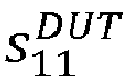
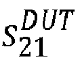
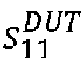
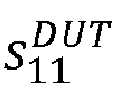
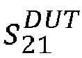
- a two-port DUT 206 has four S-parameters: reflection coefficients s 11 DUT , s 22 DUT and insertion loss and/or crosstalk terms s 12 DUT , s 21 DUT .
- the synchronized trigger 208 between the signal generator 202 and the real-time oscilloscope 200 provides an absolute time reference for the reflection coefficients and the insertion loss and/or crosstalk coefficients.
- This synchronizing action establishes a zero time or zero phase reference point for the acquisition system of the oscilloscope 200.
- Signal generator 202 may either output sweep sine signals or fast step signals that may cover a wide bandwidth. For example, a fast step signal can cover more than 50 GHz bandwidth. For swept sine signals, zero phase is the reference point. For fast step signals, zero time is the reference point.
- Power divider 204 may be any type of power divider or splitter.
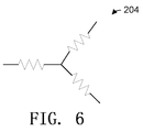
- power divider 204 may be a power divider having three 16 2/3 Ohm resistors at three branches creating a three way power network, as seen in Figure 6 .
- Figure 3 illustrates a signal flow diagram of the system shown in Figure 2 .
- the S-parameters of the power divider 204 may be measured ahead of time and saved in a memory (not shown) of the real-time oscilloscope 200.
- the DUT 206 is modeled as a two port S-parameters data set S DUT .
- port two 212 of the DUT 206 is terminated with an ideal 50 Ohm resistor 214.
- the signal generator 202 is modeled with its ideal voltage v s and has the reflection coefficient s 22 ss at the output port.
- the real-time oscilloscope 200 has the reflection coefficient s 11 scope at its input port.
- v s is the voltage source value of the signal generator 202 and may be obtained during a calibration process and saved in the memory of the real-time oscilloscope 200.
- b 2 is the voltage acquired by the oscilloscope 200 when v s is generated, so it is known.
- all the S-parameter terms for the power divider 204 may be measured ahead of time, and stored in the memory of the oscilloscope 200.
- S 22 ss corresponding to the signal source output impedance, may also be measured ahead of time and stored in memory.
- s 11 scope corresponding to the real-time oscilloscope 200 input impedance may be measured ahead of time and stored in the memory as well.
- s ⁇ 11 DUT which may be computed from equation (7).
- s 11 DUT the reflection coefficient of the DUT 206 may be calculated using equation (4) above.
- Equation (7) may be simplified with some assumptions.
- Equation (12) provides a working practical approximation of the reflection coefficient of the DUT 206.
- the port two reflection coefficient of the DUT 206, port two 212 of DUT 206 is connected to port one of the power divider 202 and port one 210 of the DUT 206 is terminated with an ideal 50 Ohm resistor 214. Then, the same procedure used to measure the port one 210 reflection coefficient s 11 DUT , discussed above may be repeated to calculate the port two 212 reflection coefficient s 22 DUT .
- the insertion loss and/or crosstalk terms s 12 DUT , s 21 DUT may be measured using the system shown in Figure 4 .
- This system includes the signal generator 202, the DUT 206, the real-time oscilloscope 200 and the synchronized trigger 208.
- the synchronized trigger 208 provides the time reference so the phases of the measured S-parameters are correct.
- the signal flow diagram of the system in Figure 4 can be seen in Figure 5 .
- port two of DUT 206 is connected to the signal generator 202, port one of DUT 206 is connected to the real-time oscilloscope 200, and the same procedure that measures s 21 DUT may be repeated to measure s 12 DUT .
- the method described above may be expanded to measure the reflection coefficients and insertion loss and crosstalk terms for a multi-port DUT.
- the reflection coefficients can be measured and calculated by terminating all the other ports of the DUT, except the port connected to the power divider, with an ideal 50 Ohms, using the method described above.
- the insertion loss and crosstalk terms may be measured by terminating all other ports except two ports connected to the signal generator and to the real-time oscilloscope, using the above-discussed insertion loss and crosstalk measurement method.
- Examples may provide a method for determining scattering parameters of a device under test using a real-time oscilloscope, comprising: determining a reflection coefficient of each port of a device under test with N ports, wherein N is an integer greater than or equal to one, including: terminating the ports of the device under test not being measured with a resistor, and calculating the reflection coefficient of the port of the device under test based on a first voltage measured by the digital oscilloscope when a signal is generated from a signal generator; and determining an insertion loss coefficient of each port of the device under test, including calculating the insertion loss coefficient of the port of the device under test based on a second voltage measured by the digital oscilloscope when a signal is generated from a signal generator; and providing an absolute time reference between the signal generator and the digital oscill
- Some examples further comprise sending the signal generated from the signal generator to a first port of a power divider; and measuring the first voltage by the real-time oscilloscope at a second port of the power divider based on the generated signal while the device under test is connected to a third port of the power divider.
- N is two, and the example method further comprises sending the signal generated from the signal generator to the port of the device under test not being measured and to the real-time oscilloscope; and measuring the second voltage by the real-time oscilloscope at the port of the device under test being measured based on the generated signal.
- N is greater than two, and the example method further comprises sending the signal generated from the signal generator to one port of the device under test not being measured and to the real-time oscilloscope; terminating the remaining ports of the device under test not being measured with a resistor; and measuring the second voltage by the real-time oscilloscope at the port of the device under test being measured based on the generated signal.
- the resistor is a 50 Ohm resistor.
- Examples also provide a test and measurement system, comprising: a power divider; a signal generator in communication with the power divider or a device under test, the signal generator configured to generate a signal; and a real-time oscilloscope in communication with the signal generator, the power divider and the device under test, the real-time oscilloscope configured to: calculate a reflection coefficient of each port of a device under test with N ports, wherein N is greater than one, measured based on a first voltage measured by the real-time oscilloscope when a signal is generated from a signal generator, and calculating an insertion loss coefficient of the port of the device under test to be measured based on a second voltage measured by the real-time oscilloscope when a signal is generated from a signal generator.
- Some examples further comprise a synchronized trigger configured to provide an absolute time reference between the signal generator and the real-time oscilloscope.
- the real-time oscilloscope is further configured to measure the first voltage by the real-time oscilloscope at a second port of the power divider based on a generated signal while the device under test is connected to a third port of the power divider.
- N is two, wherein the signal generated from the signal generator is sent to the port of the device under test not being measured and to the real-time oscilloscope; and wherein the real-time oscilloscope is further configured to measure the second voltage by the real-time oscilloscope at the port of the device under test being measured based on the generated signal.
- the calculated reflection coefficient of the first port of the device under test is s 11 DUT and the calculated reflection coefficient of the second port of the device under test is s 11 DUT
Landscapes
- Physics & Mathematics (AREA)
- General Physics & Mathematics (AREA)
- Engineering & Computer Science (AREA)
- General Engineering & Computer Science (AREA)
- Measurement Of Resistance Or Impedance (AREA)
Abstract
Description
- This disclosure relates to a method for measuring complete two-port and multi-port scattering parameters (S-parameters) of a device under test (DUT) using a real-time oscilloscope, a power divider and a signal source.
- Traditionally a vector network analyzer or a time-domain reflectometer (TDR) system with a sampling oscilloscope has been required to obtain S-parameter measurements for characterizations of a device under test (DUT). If a fixture is used to measure the S-parameters, then once the S-parameters of the fixture have been measured and the S-parameters of the DUT plus the fixture have been measured, a full de-embed operation can be performed to obtain only characteristics of the DUT by taking out the errors due to the fixture. However, vector network analyzers and TDR systems are expensive.
- As bit rate goes higher, high speed serial data link simulation and measurements require using S-parameters of the DUT to characterize the components within the simulated link for embedding and de-embedding operations. For example, as seen in
Figure 1 , the output impedance of thetransmitter 100, the input impedance of thereceiver 102, and the full S-parameters of thechannel 104 are all needed to fully characterize and simulate the link so that accurate test and measurements of the DUT may be made. - Real-time oscilloscopes are widely used to do high speed serial data link debugging, testing, and measurements. It is desired to use the real-time oscilloscopes to also measure the S-parameters of the DUT and then use the measured S-parameters for other measurements and simulations, without having to use multiple instruments.
- Embodiments of the disclosed technology address these and other limitations in the prior art.
- Certain embodiments of the disclosed technology include a method for determining scattering parameters of a device under test using a real-time oscilloscope. The method includes determining a reflection coefficient of each port of a device under test with N ports, wherein N is an integer greater than or equal to one, including terminating the ports of the device under test not being measured with a resistor, and calculating the reflection coefficient of the port of the device under test to be measured based on a first voltage measured by the real-time oscilloscope when a signal is generated from a signal generator. The method also includes determining an insertion loss and/or crosstalk coefficient between two different ports of the device under test, including calculating the insertion loss and/or a crosstalk between the ports of the device under test to be measured based on a second voltage measured by the real-time oscilloscope when a signal is generated from a signal generator.
- Certain embodiments of the disclosed technology also include a system, comprising a power divider, a signal generator in communication with the power divider, the real-time oscilloscope and/or a device under test, the signal generator configured to generate a signal, and a real-time oscilloscope in communication with the signal generator, the power divider and the device under test. The real-time oscilloscope is configured to calculate a reflection coefficient of each port of a device under test with N ports, wherein N is greater than or equal to one, measured based on a first voltage measured by the real-time oscilloscope when a signal is generated from a signal generator, and calculating an insertion loss and/or a crosstalk between the ports of the device under test to be measured based on a second voltage measured by the real-time oscilloscope when a signal is generated from a signal generator. A synchronized trigger between the signal generator and the real-time oscilloscope provides an absolute time reference for return loss coefficient, insertion loss and cross talk measurements.
-
-
Figure 1 illustrates a serial data link system. -
Figure 2 is a block diagram of a return loss coefficient measurement system according to embodiments of the disclosed technology. -
Figure 3 is a signal flow diagram of the system shown inFigure 2 . -
Figure 4 is a block diagram of an insertion loss measurement system according to embodiments of the disclosed technology. -
Figure 5 is a signal flow diagram of the system shown inFigure 4 . -
Figure 6 is a power divider ofFigure 2 . - In the drawings, which are not necessarily to scale, like or corresponding elements of the disclosed systems and methods are denoted by the same reference numerals.
- The disclosed technology measures S-parameters of a
DUT 206 using a real-time oscilloscope 200, asignal generator 202, and apower divider 204, as shown inFigure 2 . A two-port DUT 206 has four S-parameters: reflection coefficients


- In the setup shown in
Figure 2 , thesynchronized trigger 208 between thesignal generator 202 and the real-time oscilloscope 200 provides an absolute time reference for the reflection coefficients and the insertion loss and/or crosstalk coefficients. This synchronizing action establishes a zero time or zero phase reference point for the acquisition system of theoscilloscope 200.Signal generator 202 may either output sweep sine signals or fast step signals that may cover a wide bandwidth. For example, a fast step signal can cover more than 50 GHz bandwidth. For swept sine signals, zero phase is the reference point. For fast step signals, zero time is the reference point. -
Power divider 204 may be any type of power divider or splitter. For example,power divider 204 may be a power divider having three 16 2/3 Ohm resistors at three branches creating a three way power network, as seen inFigure 6 . -
Figure 3 illustrates a signal flow diagram of the system shown inFigure 2 . - The
power divider 204, as seen in the signal flow diagram ofFigure 3 , is a three-port network and characterized by a three port S-parameters data set:
- The S-parameters of the
power divider 204 may be measured ahead of time and saved in a memory (not shown) of the real-time oscilloscope 200. The DUT 206 is modeled as a two port S-parameters data set SDUT . - To measure the reflection coefficient
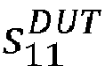
DUT 206, port two 212 of theDUT 206 is terminated with an ideal 50Ohm resistor 214. Thesignal generator 202 is modeled with its ideal voltage vs and has the reflection coefficient
time oscilloscope 200 has the reflection coefficient
- As the power divider is a three-port network, with port two being terminated by
DUT 206, a two-port system can be derived from port one and port three of thepower divider 204 as follows:



- From equation (2), the transfer function from the voltage source of the
signal generator 202 to the input to the real-time oscilloscope can be derived as:

- In equation (7), vs is the voltage source value of the
signal generator 202 and may be obtained during a calibration process and saved in the memory of the real-time oscilloscope 200. b 2 is the voltage acquired by theoscilloscope 200 when vs is generated, so it is known. As discussed above, all the S-parameter terms for thepower divider 204 may be measured ahead of time, and stored in the memory of theoscilloscope 200.

time oscilloscope 200 input impedance, may be measured ahead of time and stored in the memory as well. The only unknown, therefore, is


DUT 206 may be calculated using equation (4) above. - Equation (7) may be simplified with some assumptions. First, the S-parameters of an ideal power divider is:


- Assuming the S-parameters of the
power divider 204,signal generator 202, and real-time oscilloscope 200 are their ideal models, then equation (7) can be simplified as:
- However, in the real world, the S-parameters of the
power divider 204,signal generator 202 and real-time oscilloscope 200 will not be ideal, but the following may be assumed to be true:

DUT 206. - To measure

DUT 206, port two 212 ofDUT 206 is connected to port one of thepower divider 202 and port one 210 of theDUT 206 is terminated with an ideal 50Ohm resistor 214. Then, the same procedure used to measure the port one 210 reflection coefficient

- The insertion loss and/or crosstalk terms


Figure 4 . This system includes thesignal generator 202, theDUT 206, the real-time oscilloscope 200 and thesynchronized trigger 208. The synchronizedtrigger 208 provides the time reference so the phases of the measured S-parameters are correct. The signal flow diagram of the system inFigure 4 can be seen inFigure 5 . - The transfer function from the signal generator's 202 voltage source to the input to the real-time oscilloscope can be derived in the same way as equation (6):


oscilloscope 200 when vs is generated when the devices are configured as inFigure 4 . - To measure

DUT 206 is connected to thesignal generator 202, port one ofDUT 206 is connected to the real-time oscilloscope 200, and the same procedure that measures

- The method described above may be expanded to measure the reflection coefficients and insertion loss and crosstalk terms for a multi-port DUT. To measure an N-port network, the reflection coefficients can be measured and calculated by terminating all the other ports of the DUT, except the port connected to the power divider, with an ideal 50 Ohms, using the method described above. Then, the insertion loss and crosstalk terms may be measured by terminating all other ports except two ports connected to the signal generator and to the real-time oscilloscope, using the above-discussed insertion loss and crosstalk measurement method.
- Having described and illustrated the principles of the disclosed technology in a preferred embodiment thereof, it should be apparent that the disclosed technology can be modified in arrangement and detail without departing from such principles. We claim all modifications and variations coming within the scope of the following claims.
Examples may provide a method for determining scattering parameters of a device under test using a real-time oscilloscope, comprising: determining a reflection coefficient of each port of a device under test with N ports, wherein N is an integer greater than or equal to one, including: terminating the ports of the device under test not being measured with a resistor, and calculating the reflection coefficient of the port of the device under test based on a first voltage measured by the digital oscilloscope when a signal is generated from a signal generator; and determining an insertion loss coefficient of each port of the device under test, including calculating the insertion loss coefficient of the port of the device under test based on a second voltage measured by the digital oscilloscope when a signal is generated from a signal generator; and providing an absolute time reference between the signal generator and the digital oscilloscope through a synchronized trigger. - Some examples further comprise sending the signal generated from the signal generator to a first port of a power divider; and measuring the first voltage by the real-time oscilloscope at a second port of the power divider based on the generated signal while the device under test is connected to a third port of the power divider.
- In some examples, N is two, and the example method further comprises sending the signal generated from the signal generator to the port of the device under test not being measured and to the real-time oscilloscope; and measuring the second voltage by the real-time oscilloscope at the port of the device under test being measured based on the generated signal.
- In some examples, N is greater than two, and the example method further comprises sending the signal generated from the signal generator to one port of the device under test not being measured and to the real-time oscilloscope; terminating the remaining ports of the device under test not being measured with a resistor; and measuring the second voltage by the real-time oscilloscope at the port of the device under test being measured based on the generated signal.
- In some examples the resistor is a 50 Ohm resistor.
- In some examples the reflection coefficient is calculated using the equations:


- where b 2 is the first voltage,
- vs is the generated signal,
-

- s 21, s 12, s 31, s 23, s 32, s 33 are the scatter parameter terms of the power divider,
-

-
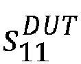
- In some examples the N is two and the reflection coefficients are calculated for each port using the equations:

- where b 2 is the first voltage,
- vs is the generated signal,
-

- s21, s125 s31, s23, s 32, s 33 are the scatter parameter terms of the power divider,
-

-

- In some examples the calculated reflection coefficient of the first port of the device under test is


- Examples also provide a test and measurement system, comprising: a power divider; a signal generator in communication with the power divider or a device under test, the signal generator configured to generate a signal; and a real-time oscilloscope in communication with the signal generator, the power divider and the device under test, the real-time oscilloscope configured to: calculate a reflection coefficient of each port of a device under test with N ports, wherein N is greater than one, measured based on a first voltage measured by the real-time oscilloscope when a signal is generated from a signal generator, and calculating an insertion loss coefficient of the port of the device under test to be measured based on a second voltage measured by the real-time oscilloscope when a signal is generated from a signal generator.
- Some examples further comprise a synchronized trigger configured to provide an absolute time reference between the signal generator and the real-time oscilloscope.
- In some examples, the real-time oscilloscope is further configured to measure the first voltage by the real-time oscilloscope at a second port of the power divider based on a generated signal while the device under test is connected to a third port of the power divider.
- In some examples, N is two, wherein the signal generated from the signal generator is sent to the port of the device under test not being measured and to the real-time oscilloscope; and wherein the real-time oscilloscope is further configured to measure the second voltage by the real-time oscilloscope at the port of the device under test being measured based on the generated signal.
- In some examples, N is two and the real-time oscilloscope is further configured to calculate the reflection coefficients for each port using the equations:


- where b 2 is the first voltage,
- vs is the generated signal,
-

- s21, s12, s31, s23, s 32, s 33 are the scatter parameter terms of the power divider,
-

-
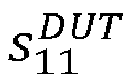
- In some examples, the calculated reflection coefficient of the first port of the device under test is


Claims (14)
- A method for determining scattering parameters of a device under test using a real-time oscilloscope, comprising:determining a reflection coefficient of each port of a device under test with N ports, wherein N is an integer greater than or equal to one, including:terminating the ports of the device under test not being measured with a resistor,and calculating the reflection coefficient of the port of the device under test based on a first voltage measured by the digital oscilloscope when a signal is generated from a signal generator; anddetermining an insertion loss coefficient of each port of the device under test, including calculating the insertion loss coefficient of the port of the device under test based on a second voltage measured by the digital oscilloscope when a signal is generated from a signal generator; andproviding an absolute time reference between the signal generator and the digital oscilloscope through a synchronized trigger.
- The method of claim 1, further comprising:sending the signal generated from the signal generator to a first port of a power divider; andmeasuring the first voltage by the real-time oscilloscope at a second port of the power divider based on the generated signal while the device under test is connected to a third port of the power divider.
- The method of claim 1 or 2, wherein N is two, the method further comprising:sending the signal generated from the signal generator to the port of the device under test not being measured and to the real-time oscilloscope; andmeasuring the second voltage by the real-time oscilloscope at the port of the device under test being measured based on the generated signal.
- The method of claim 1 or 2, wherein N is greater than two, the method further comprising:sending the signal generated from the signal generator to one port of the device under test not being measured and to the real-time oscilloscope;terminating the remaining ports of the device under test not being measured with a resistor; andmeasuring the second voltage by the real-time oscilloscope at the port of the device under test being measured based on the generated signal.
- The method of any of claims 1 to 4, wherein the resistor is a 50 Ohm resistor.
- The method of claim 2, wherein the reflection coefficient is calculated using the equations:

 where b 2 is the first voltage,vs is the generated signal,
 s21, s12, s31, s23, s 32, s 33 are the scatter parameter terms of the power divider,

- The method of claim 3, wherein N is two and the reflection coefficients are calculated for each port using the equations:
 where b 2 is the first voltage,vs is the generated signal,
 s21, s12, s31, s23, s 32, s 33 are the scatter parameter terms of the power divider,
- The method of claim 7, wherein the calculated reflection coefficient of the first port of the device under test is


wherein the insertion loss coefficient is calculated for each port using the equation:

- A test and measurement system, comprising:a power divider;a signal generator in communication with the power divider or a device under test, the signal generator configured to generate a signal; anda real-time oscilloscope in communication with the signal generator, the power divider and the device under test, the real-time oscilloscope configured to:calculate a reflection coefficient of each port of a device under test with N ports, wherein N is greater than one, measured based on a first voltage measured by the real-time oscilloscope when a signal is generated from a signal generator, andcalculating an insertion loss coefficient of the port of the device under test to be measured based on a second voltage measured by the real-time oscilloscope when a signal is generated from a signal generator.
- The system of claim 9, further comprising a synchronized trigger configured to provide an absolute time reference between the signal generator and the real-time oscilloscope.
- The system of claim 9, wherein the real-time oscilloscope is further configured to measure the first voltage by the real-time oscilloscope at a second port of the power divider based on a generated signal while the device under test is connected to a third port of the power divider.
- The system of claim 11, wherein N is two,
wherein the signal generated from the signal generator is sent to the port of the device under test not being measured and to the real-time oscilloscope; and
wherein the real-time oscilloscope is further configured to measure the second voltage by the real-time oscilloscope at the port of the device under test being measured based on the generated signal. - The system of claim 12, wherein N is two and the real-time oscilloscope is further configured to calculate the reflection coefficients for each port using the equations:

and where b 2 is the first voltage,vs is the generated signal,
 s21, s125 s31, s23, s 32, s 33 are the scatter parameter terms of the power divider,

- The system of claim 13, wherein the calculated reflection coefficient of the first port of the device under test is

wherein real-time oscilloscope is further configured to calculate the insertion loss coefficient for each port using the equation:
Applications Claiming Priority (2)
| Application Number | Priority Date | Filing Date | Title |
|---|---|---|---|
| US201462026434P | 2014-07-18 | 2014-07-18 | |
| US14/673,747 US10145874B2 (en) | 2014-07-18 | 2015-03-30 | S-parameter measurements using real-time oscilloscopes |
Publications (1)
| Publication Number | Publication Date |
|---|---|
| EP3051302A1 true EP3051302A1 (en) | 2016-08-03 |
Family
ID=55074398
Family Applications (1)
| Application Number | Title | Priority Date | Filing Date |
|---|---|---|---|
| EP15178972.4A Withdrawn EP3051302A1 (en) | 2014-07-18 | 2015-07-29 | S-parameter measurements using real-time oscilloscopes |
Country Status (4)
| Country | Link |
|---|---|
| US (1) | US10145874B2 (en) |
| EP (1) | EP3051302A1 (en) |
| JP (1) | JP2016024197A (en) |
| CN (1) | CN105277800A (en) |
Families Citing this family (14)
| Publication number | Priority date | Publication date | Assignee | Title |
|---|---|---|---|---|
| US10345339B2 (en) | 2015-12-09 | 2019-07-09 | Tektronix, Inc. | Group delay based averaging |
| CN105759197B (en) * | 2016-03-28 | 2018-06-12 | 工业和信息化部电子第五研究所 | DDS devices single particle effect unusual waveforms capture systems and its catching method |
| EP3239795A1 (en) * | 2016-04-27 | 2017-11-01 | ABB Schweiz AG | A method and system for commissioning and optimization of a production line |
| US10473719B2 (en) * | 2017-10-12 | 2019-11-12 | Keysight Technologies, Inc. | System and method for separating and measuring two signals simultaneously present on a signal line |
| US10732222B2 (en) | 2018-03-29 | 2020-08-04 | Rohde & Schwarz Gmbh & Co. Kg | Real-time oscilloscope with a built-in time domain reflectometry (TDR) and/or time-domain transmission (TDT) function |
| CN108614162B (en) * | 2018-05-02 | 2020-06-09 | 上海交通大学 | Microwave photon vector network analysis device and method for measuring scattering parameters of microwave device |
| CN110967537B (en) * | 2018-10-01 | 2024-08-30 | 特克特朗尼克公司 | Monitor the waveform from the waveform generator at the device under test |
| CN109507499B (en) * | 2018-11-07 | 2021-10-26 | 中电科思仪科技股份有限公司 | S parameter detection device and method |
| CN109444717B (en) | 2018-11-27 | 2020-08-18 | 中国电子科技集团公司第十三研究所 | Novel on-chip S parameter error calibration method and device |
| US11598805B2 (en) * | 2019-06-06 | 2023-03-07 | Tektronix, Inc. | Low frequency S-parameter measurement |
| DE102020114908A1 (en) * | 2019-06-06 | 2020-12-10 | Tektronix, Inc. | LOW FREQUENCY S PARAMETER MEASUREMENT |
| CN113009201B (en) | 2021-02-24 | 2022-08-23 | 普源精电科技股份有限公司 | Electric signal sampling device |
| US12372561B2 (en) * | 2023-08-25 | 2025-07-29 | Keysight Technologies, Inc. | System and method for measuring modulation distortion error vector magnitude (EVM) of a device under test (DUT) |
| CN119471532B (en) * | 2025-01-13 | 2025-04-11 | 中国计量科学研究院 | Calibration factor estimation correction method for radio frequency high-power calibration direct measurement method |
Citations (1)
| Publication number | Priority date | Publication date | Assignee | Title |
|---|---|---|---|---|
| US20040027138A1 (en) * | 2002-08-07 | 2004-02-12 | Pickerd John J. | Oscilloscope based return loss analyzer |
Family Cites Families (4)
| Publication number | Priority date | Publication date | Assignee | Title |
|---|---|---|---|---|
| US4139817A (en) * | 1976-09-13 | 1979-02-13 | Tektronix, Inc. | Impedance-switching connector |
| US20050185769A1 (en) * | 2004-02-25 | 2005-08-25 | Pickerd John J. | Calibration method and apparatus |
| US7402821B2 (en) * | 2006-01-18 | 2008-07-22 | Axcelis Technologies, Inc. | Application of digital frequency and phase synthesis for control of electrode voltage phase in a high-energy ion implantation machine, and a means for accurate calibration of electrode voltage phase |
| US9618599B2 (en) | 2011-09-28 | 2017-04-11 | Keysight Technologies, Inc. | Characterization and correction of voltage probe, current probe and cable |
-
2015
- 2015-03-30 US US14/673,747 patent/US10145874B2/en not_active Expired - Fee Related
- 2015-07-16 JP JP2015142303A patent/JP2016024197A/en active Pending
- 2015-07-17 CN CN201510422210.4A patent/CN105277800A/en not_active Withdrawn
- 2015-07-29 EP EP15178972.4A patent/EP3051302A1/en not_active Withdrawn
Patent Citations (1)
| Publication number | Priority date | Publication date | Assignee | Title |
|---|---|---|---|---|
| US20040027138A1 (en) * | 2002-08-07 | 2004-02-12 | Pickerd John J. | Oscilloscope based return loss analyzer |
Non-Patent Citations (3)
| Title |
|---|
| HENZE A ET AL: "1 GHz automatic 2-Port Vector Network Analyzer using common laboratory instruments", 2014 IEEE INTERNATIONAL INSTRUMENTATION AND MEASUREMENT TECHNOLOGY CONFERENCE (I2MTC) PROCEEDINGS, IEEE, 12 May 2014 (2014-05-12), pages 170 - 174, XP032620789, DOI: 10.1109/I2MTC.2014.6860726 * |
| K. EL-AKHDAR ET AL: "Calibrated oscilloscopic system for RF time-domain characterization of non-linear devices", 2013 13TH MEDITERRANEAN MICROWAVE SYMPOSIUM (MMS), 1 September 2013 (2013-09-01), pages 1 - 4, XP055284158, ISBN: 978-1-4673-5820-0, DOI: 10.1109/MMS.2013.6663103 * |
| MAKAROV: "N2PK Vector Network Analyzer", 27 January 2007 (2007-01-27), XP055284150, Retrieved from the Internet <URL:http://www.makarov.ca/vna_bridge_hack.htm> [retrieved on 20160628] * |
Also Published As
| Publication number | Publication date |
|---|---|
| CN105277800A (en) | 2016-01-27 |
| US20160018450A1 (en) | 2016-01-21 |
| JP2016024197A (en) | 2016-02-08 |
| US10145874B2 (en) | 2018-12-04 |
Similar Documents
| Publication | Publication Date | Title |
|---|---|---|
| US10145874B2 (en) | S-parameter measurements using real-time oscilloscopes | |
| JP6499177B2 (en) | Method for calibrating inspection equipment configuration | |
| US6853198B2 (en) | Method and apparatus for performing multiport through-reflect-line calibration and measurement | |
| CN103399286B (en) | A kind of measurement calibration steps of many characteristic impedance network | |
| US7739063B2 (en) | Nonlinear measurement system error correction | |
| US8860434B2 (en) | Method of measuring scattering parameters of device under test | |
| US20110238383A1 (en) | One-Port De-embedding Using Time Domain Substitution | |
| US20140343883A1 (en) | User Interface for Signal Integrity Network Analyzer | |
| US20110286506A1 (en) | User Interface for Signal Integrity Network Analyzer | |
| EP2853911A1 (en) | Two port vector network analyzer using de-embed probes | |
| US7030625B1 (en) | Method and apparatus for performing a minimum connection multiport through-reflect-line calibration and measurement | |
| EP3376239A2 (en) | Mixed mode vector network analyser | |
| US9903932B2 (en) | Measuring system, calibration device and measuring method with uncertainty analysis | |
| US20070073499A1 (en) | Method and apparatus for determining one or more s-parameters associated with a device under test (DUT) | |
| US20110234239A1 (en) | Two-Port De-Embedding Using Time Domain Substitution | |
| US20170074911A1 (en) | Time domain measuring method with calibration in the frequency range | |
| WO2008021907A2 (en) | Calibrated s-parameter measurements of probes | |
| US10591522B2 (en) | Measurement apparatus | |
| CN104777370A (en) | Automatic fixture removal using one-port measurement | |
| CN106771849A (en) | Two method of testings of impedance discontinuity point reflection response on a kind of transmission line | |
| CN107064610B (en) | Group delay based averaging | |
| D'Aucelli et al. | LineLab-A transmission line simulator for distributed sensing systems: Open-source MATLAB code for simulating real-world transmission lines | |
| Dahlberg et al. | A method to determine LRRM calibration standards in measurement configurations affected by leakage | |
| US20070197169A1 (en) | Systems and methods for transmitter and channel characterization | |
| Dvorak et al. | Removal of time-varying errors in network-analyser measurements: signal normalisation and test results |
Legal Events
| Date | Code | Title | Description |
|---|---|---|---|
| PUAI | Public reference made under article 153(3) epc to a published international application that has entered the european phase |
Free format text: ORIGINAL CODE: 0009012 |
|
| AK | Designated contracting states |
Kind code of ref document: A1 Designated state(s): AL AT BE BG CH CY CZ DE DK EE ES FI FR GB GR HR HU IE IS IT LI LT LU LV MC MK MT NL NO PL PT RO RS SE SI SK SM TR |
|
| AX | Request for extension of the european patent |
Extension state: BA ME |
|
| RIN1 | Information on inventor provided before grant (corrected) |
Inventor name: TAN, KAN Inventor name: PICKERD, JOHN |
|
| 17P | Request for examination filed |
Effective date: 20170202 |
|
| RBV | Designated contracting states (corrected) |
Designated state(s): AL AT BE BG CH CY CZ DE DK EE ES FI FR GB GR HR HU IE IS IT LI LT LU LV MC MK MT NL NO PL PT RO RS SE SI SK SM TR |
|
| STAA | Information on the status of an ep patent application or granted ep patent |
Free format text: STATUS: THE APPLICATION HAS BEEN WITHDRAWN |
|
| 18W | Application withdrawn |
Effective date: 20190425 |