EP3051278B1 - 3d thermal diffusivity - Google Patents
3d thermal diffusivity Download PDFInfo
- Publication number
- EP3051278B1 EP3051278B1 EP16000205.1A EP16000205A EP3051278B1 EP 3051278 B1 EP3051278 B1 EP 3051278B1 EP 16000205 A EP16000205 A EP 16000205A EP 3051278 B1 EP3051278 B1 EP 3051278B1
- Authority
- EP
- European Patent Office
- Prior art keywords
- sensor
- heat
- sample
- axis
- source
- Prior art date
- Legal status (The legal status is an assumption and is not a legal conclusion. Google has not performed a legal analysis and makes no representation as to the accuracy of the status listed.)
- Active
Links
Images




Classifications
-
- G—PHYSICS
- G01—MEASURING; TESTING
- G01N—INVESTIGATING OR ANALYSING MATERIALS BY DETERMINING THEIR CHEMICAL OR PHYSICAL PROPERTIES
- G01N25/00—Investigating or analyzing materials by the use of thermal means
- G01N25/18—Investigating or analyzing materials by the use of thermal means by investigating thermal conductivity
-
- G—PHYSICS
- G01—MEASURING; TESTING
- G01N—INVESTIGATING OR ANALYSING MATERIALS BY DETERMINING THEIR CHEMICAL OR PHYSICAL PROPERTIES
- G01N25/00—Investigating or analyzing materials by the use of thermal means
- G01N25/20—Investigating or analyzing materials by the use of thermal means by investigating the development of heat, i.e. calorimetry, e.g. by measuring specific heat, by measuring thermal conductivity
Definitions
- the present invention relates to a system for measuring the thermal diffusivity of a material according to the preamble of claim 1.
- measurement systems and methods and, more particularly, systems and methods for measuring three-dimensional (3D) diffusivity are described therein.
- Thermal diffusivity is a measurement of the ability of a material to conduct thermal energy relative to its ability to store thermal energy. It may be calculated using the material's thermal conductivity (W/(m ⁇ K)) divided by its density (kg/m 3 ) and specific heat capacity (J/(kg ⁇ K)). As an example, heat moves rapidly through a substance with high thermal diffusivity because the substance conducts heat quickly relative to its volumetric heat capacity.
- Thermal diffusivity may be measured using the "flash” method. This involves heating a sample of material (e.g., a strip or cylindrical sample, etc.) with a short energy pulse (e.g., heat source such as a light beam, laser, etc.). The temperature change in the sample may then be measured over time.
- a short energy pulse e.g., heat source such as a light beam, laser, etc.
- the assignee of the present application is a manufacturer of flash systems used to measure thermal diffusivity.
- One such system is the LFA 447 NanoFlash ® .
- the LFA 447 is a compact measuring system, with the flash lamp, sample plate, and sensor vertically arranged. Samples of material are placed on an automatic sample changer, which can test up to four samples. Using the LFA 447, a first side of a sample of material is heated by a short light pulse. The resulting temperature rise on the sample's other side is measured using an infrared sensor. By analyzing the resulting temperature-versus-time curve, the thermal diffusivity of the sample of material can be determined.
- a system according to the preamble of claim 1 is known from the publication US 2014/036955 A1 , which discloses a device and method for the photothermic investigation of a sample. It uses a sample holder that is movable in relation to a fixed optical excitation/detection path.
- U.S. Pat. No. 6,273,603 to Cheindline discloses a measuring head for use in radiant energy flash measuring of the thermal diffusivity of samples. It uses a movable sample holder and a fixed side view detector, which requires a mirror moving in three coordinates to reflect light from the sample. Neither of these references disclose use of a mask.
- thermometer is scanned in two dimensions in parallel to the sample by a stepping motor which moves in an X-axis direction and a stepping motor which moves in a Z-axis direction.
- excitation beam is scanned across the sample using an objective lens, such that an angle of the probe beam with respect to the sample surface changes when the probe beam is scanned across the sample surface.
- Testing of thermal diffusivity may be desirable in any number of different fields. For example, it may be desirable to determine how to improve the heat transfer of an electronic component. It may also be desirable to determine the optimum materials for a heat exchanger system in order to achieve a required efficiency. It may also be desirable to determine the heating/cooling load of a building as a function of weather conditions in order to determine how building materials can be improved. It may also be desirable to determine how fast an aluminum ingot solidifies, how to minimize thermal stresses within a steel block, how to optimize the manufacturing of glass bottles, how fast ceramic components in a catalytic converter heat up, how to select the correct heat exchanger material for the thermal control of a processor, etc.
- One skilled in the art would appreciate the various applications for the present teachings, which are not limited to any particular embodiments disclosed herein.
- measuring heat transfer is important not only in many scientific areas but in many industrial ones as well.
- the heat transfer can have a major impact on the thermophysical properties of the solid.
- a variety of materials, whether made of chemicals or mixtures, have a homogenous composition.
- the thermal conductivity is a true physical property, depending on temperature, pressure and composition.
- the thermal diffusivity and thermal conductivity also depend on the direction of the heat flow. Such challenges, and many others, cannot be met without accurate knowledge about the thermal properties of diffusivity and conductivity.
- the flash technique is a preferable choice for measuring thermal diffusivity by providing a noncontact test method having easy sample preparation, fast testing times, and high accuracy. It can also cover a broad range of applications and temperatures, including from -125°C up to 2800°C, although not limited thereto.
- the sensor 100 and source 102 are fixed on a central axis of a sample.
- the sample is fixed in a sample plate 104.
- the sample plate 104 may be capable of holding multiple samples.
- Each sample may be in the shape of a disk, although other shapes would be appreciated by one skilled in the art.
- Each disk has a central axis at (or near) its center point, the center axis generally orthogonal to the plane of the disk (also perpendicular to the plate). Movement 106 of the sample plate 104 is restricted to a single preset position on each sample such that a central axis of the sample is on the same axis as the sensor 100 and source 102. As a result, such known systems only provide for testing a sample in a single direction through the thickness of the sample.
- the present teachings are desirable for a number of end-users, including universities, research labs, and materials manufacturers, although not limited thereto. They can be used to test any number of different materials, including plastics, ceramics, metals, composites, and multi-layer systems, etc. In an increasingly competitive technological environment, efficiently devised heat transfer processes are desirable.
- a system according to the present teachings allows for the consideration of radial and facial heat losses through a sample of material in any number of directions.
- finite pulse effects can be comprehensively analyzed using advanced mathematical regression routines.
- thermal diffusivity and specific heat can be determined simultaneously - on the same sample - thus yielding thermal conductivity if the density is known.
- the system may be designed as a unitary system in a housing 101, although it is to be appreciated that the housing 101 may comprise separate components (e.g., multiple housing elements). It may be designed as a vertical system with a source 102 at a bottom portion of the housing and a sensor 100 at an upper portion of the housing, although not limited thereto.
- a system provides a fast, non-contact, and efficient method for measuring the thermophysical properties of thermal diffusivity, specific heat capacity, and thermal conductivity.
- the data acquisition rate of both the sensor and pulse mapping channels may be 2 MHz or more. Thereby, highly conductive and/or thin materials requiring very short test times can be reliably measured.
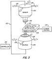
- the sensor 120 is offset from a central axis 122 of a sample of material that is held by the sample plate 124 (discussed further below in relation to FIG. 4 ).
- a configuration allows for the measuring of 3D diffusivity. For example, heat may be projected at the material and radiate along axis 122, whereas the sensor 120 may be moved at various positions offset from the axis 122. This allows for analysis of expansion, conductivity (how much heat), diffusivity (how fast heat dissipates), etc., in order to measure a "path" of diffusivity through the sample, although not limited thereto.
- the sensor 120 and source 126 may each move 128 independently or together (when joined by a frame 132, housing, or similar structure). Movement may be controlled by a controller 130 in order to provide small movements so that diffusivity can be measured at various places on the sample. According to the invention, measurements of 3D diffusivity are carried out with controlling a movement of the sensor together with the source and using a mask as exemplary described below with reference to Figs. 4 and 5 .
- a xenon lamp may serve as the source 126 and provide heat to the sample of material.
- the source 126 may be user-exchangeable and have a long lifetime.
- Variable pulse energy may be controlled by the controller 130, for example, up to 10 Joule/pulse, although not limited thereto.
- the pulse width may also be adjustable, for example, 20 to 1200 ⁇ s.
- a filter wheel can be used for further adjustments.
- the senor 120 may be an indium antimonide (InSb) sensor. This may be suitable for measuring room temperatures up to 500°C, although not limited thereto. In another embodiment, a mercury cadmium telluride (MCT) sensor may be used. This may allow for measurements from -100°C to 500°C (prior systems could only go up to 200°C), although not limited thereto. Such a design may ensure that even at cryogenic temperatures measurements are based on the energy radiation from the sample's surface. In addition, the sensor 120 may be equipped with optional liquid nitrogen auto-refill system, which may be useful for long running tests without operator intervention.
- InSb indium antimonide
- MCT mercury cadmium telluride
- MCT mercury cadmium telluride
- the sensor 120 may be equipped with optional liquid nitrogen auto-refill system, which may be useful for long running tests without operator intervention.
- the senor 120 may comprise an actuated lens 136 (e.g., zoom lens, etc.) to optimize and focus the sensor 146 (shown in Fig. 4 ).
- the actuated lens 136 may only need to move in one direction, e.g., orthogonal to the plane of the sample 144. This may reduce the complexity of components and the potential for error, although not limited thereto.
- Actuation may be provided by a stepper motor, although not limited thereto, which may be controlled by the controller 130.
- the actuated lens 136 may help to avoid signal distortions from surroundings of the sample 144, such as masks 140 or aperture stops. This may be particularly desirable for samples having a small diameter. It also helps ensure that the sensor 120 is kept within its linear responsivity range.
- the sensor field of view is fixed and made large enough to accommodate large-diameter samples.
- aperture stops are commonly used in an attempt to minimize the influence of the surroundings. This often results in a significant distortion of the thermal curve to the extent that the sensor not only senses the temperature excursion of the sample, but also any fluctuations from the aperture stop. Consequently, a thermal curve may show either a continuously increasing trend or an extended leveling-off period.
- an actuated lens 136 e.g., zoom lens, etc. helps ensure that a heat signal originates solely from the sample surface and not from any surrounding parts. Therefore, both large and small samples can be tested by narrowing focus of the sensor 146 (shown in Fig. 4 ). This is particularly helpful because in contrast with prior art systems, the sensor according to the present teachings can be offset from where the heat is projected onto the material (e.g., near an edge of the material to measure a thermal diffusivity path as heat radiates). Whereas in known systems an aperture stop could produce noticeable effects, the thermal curve according to the present teachings conforms to the theoretical model, yielding correct diffusivity values.
- an actuated lens in one embodiment may be used to shift (e.g., angle) the focus of the sensor 146 (shown in Fig. 4 ) so that it is offset from where the heat reaches the material (e.g., heat radiates along axis 122).
- the sensor 120 and source 126 may be fixed together on the same axis, which may be a central axis 122 of the sample 144. But since the actuated lens can move and focus the sensor 146 so that it is offset from axis 122 no mask may be needed. According to the invention, however, measurements of 3D diffusivity are carried out with usage of such a mask as exemplary described hereinafter.
- FIG. 4 shown is an enlarged view of one embodiment of a sample plate 124 according to FIG. 3 .
- the plate 124 includes a "mask" 140 (also shown in FIG. 5 ).
- the mask is used to direct the heat to a particular location on the sample.
- the mask 140 allows heat 142 from a source 147 to reach a sample 144 and radiate along a central axis 122, but otherwise blocks the heat from reaching the sample 144 at other areas.
- the mask allows the sensor 120 and source 126 (shown in FIG. 3 ) to be fixed on the same axis with each other (e.g., with a frame 132) so that they both can be positioned at an offset 143 from where heat is projected onto the material (e.g., heat radiates along axis 122) and measure 3D diffusivity.
- the system can measure diffusivity in various directions 141 through the sample (e.g., no longer limited to measuring diffusivity only through its axis 122 but can measure 3D diffusivity).
- sample plate 124 It may be preferable to have the sensor 120 and the source 126 move while the sample plate 124 remains fixed. This way, there is less chance that a sample may shift in the sample plate 124 (e.g., sample may be a liquid, etc.) when taking measurements from different axes on the sample.
- the mask 140 may be shaped to correspond with the shape of a sample 144 (shown in FIG. 4 ), although not limited thereto.
- the mask 140 has an opening 150 to allow heat 142 to reach the sample 144. As a result, even if the source 147 is positioned offset from a central axis 122 of the sample 144, the heat 142 will be directed to the opening 150 so that 3D diffusivity can be measured at other points 152.
- FIG. 6 shown is one embodiment of the system of FIG. 2 where the sensor 120 and source 126 may be moved separately.
- One or more controllers 130,130' may position the sensor 120 and source 126.
- the sensor 120 may be focused offset from axis 122 of the sample 144 while the source 126 is positioned on the axis 122 (or at some other axis) of the sample 144 to measure 3D diffusivity without the need for a mask 140.
- measurements of 3D diffusivity are carried out with usage of such a mask as exemplary described with reference to Figs. 4 and 5 .
- the controller 130 may have software to carry out measurements and evaluate the resulting data.
- User-friendly menus combined with automated routines may provide sophisticated analysis. Some features may include:
- the controller 130 may have various calculation models, corrections and mathematical operations. For thermal diffusivity under various boundary conditions, different baselines/models with correction of the pulse width may be used, including:
- a system according to the present teachings provides for thermal characterization of high conductivity materials at cryogenic and moderate temperatures, or ceramics and refractories at elevated temperatures, although not limited thereto. Measurements from -125°C (e.g., below the glass transition temperature of rubber materials) to 2800°C can be readily carried out with a single instrument setup, without the need for swapping a furnace or cooling device. However, different furnaces and cooling systems may be used with the modular system.
- a climate control device 134 may provide for control of heat (e.g., a furnace), cold (e.g., cooling device), pressure, and/or a gas-filled environment, although not limited thereto.
- a furnace may provide for measurements up to 500°C and higher, although not limited thereto. The design of the furnace enables thermal coupling to different cooling devices. This may reduce the measurement times and allow for heating rates up to 50 K/min or more, while maintaining an excellent thermal stability, although not limited thereto.
- Cooling devices using liquid nitrogen may allow for temperatures of -100°C and lower, although not limited thereto. Depending on a purge gas and sample, lower temperatures can be achieved.
- the cooling systems can be operated with the evacuation system running (below atmospheric pressure). This leads to a further reduction in heat loss and convection.
- a cooling system can also be operated during measurements under a defined atmosphere using a purge gas. This is advantageous when testing oxygen-sensitive samples.
- the atmosphere can also be controlled via integrated frits or via mass flow controllers both for one protective and two purge gases. All gas controls may offer operation in oxidizing, inert, dynamic or static atmospheres. Additionally, pumping allows for measurements under reduced pressure.
- a sample plate may carry round or square samples with a diameter of 12.7 mm each.
- inserts can be chosen to accommodate diameters of up to, for example, 25.4 mm or more.
- its thickness can vary between 0.01 mm and 6 mm, although not limited thereto.
- sample plates may be used for special applications on specific materials, including: molten polymers and low viscosity liquids, resins during curing, pastes and powders, fibers, laminates, etc.
- molten polymers and low viscosity liquids for liquids
- resins during curing for example, continuous contact between the liquid and a crucible may be assured over the entire temperature range- even at freezing temperatures. Heat transfer through the container wall may be minimized.
- Another sample plate may be used for measurements on resins during the curing process.
- sample plates for measurements under mechanical pressure may be used.
- One skilled in the art would appreciate the different shapes, sizes, and structures that may be used to construct sample plates according to the present teachings, which are not limited to any particular embodiments disclosed herein.
Landscapes
- Physics & Mathematics (AREA)
- Health & Medical Sciences (AREA)
- Life Sciences & Earth Sciences (AREA)
- Chemical & Material Sciences (AREA)
- Analytical Chemistry (AREA)
- Biochemistry (AREA)
- General Health & Medical Sciences (AREA)
- General Physics & Mathematics (AREA)
- Immunology (AREA)
- Pathology (AREA)
- Investigating Or Analyzing Materials Using Thermal Means (AREA)
Description
- The present invention relates to a system for measuring the thermal diffusivity of a material according to the preamble of claim 1. Generally, measurement systems and methods and, more particularly, systems and methods for measuring three-dimensional (3D) diffusivity are described therein.
- Thermal diffusivity is a measurement of the ability of a material to conduct thermal energy relative to its ability to store thermal energy. It may be calculated using the material's thermal conductivity (W/(m·K)) divided by its density (kg/m3) and specific heat capacity (J/(kg·K)). As an example, heat moves rapidly through a substance with high thermal diffusivity because the substance conducts heat quickly relative to its volumetric heat capacity.
- Thermal diffusivity may be measured using the "flash" method. This involves heating a sample of material (e.g., a strip or cylindrical sample, etc.) with a short energy pulse (e.g., heat source such as a light beam, laser, etc.). The temperature change in the sample may then be measured over time.
- The assignee of the present application is a manufacturer of flash systems used to measure thermal diffusivity. One such system is the LFA 447 NanoFlash®. The LFA 447 is a compact measuring system, with the flash lamp, sample plate, and sensor vertically arranged. Samples of material are placed on an automatic sample changer, which can test up to four samples. Using the LFA 447, a first side of a sample of material is heated by a short light pulse. The resulting temperature rise on the sample's other side is measured using an infrared sensor. By analyzing the resulting temperature-versus-time curve, the thermal diffusivity of the sample of material can be determined.
- A system according to the preamble of claim 1 is known from the publication
US 2014/036955 A1 , which discloses a device and method for the photothermic investigation of a sample. It uses a sample holder that is movable in relation to a fixed optical excitation/detection path.U.S. Pat. No. 6,273,603 to Cheindline discloses a measuring head for use in radiant energy flash measuring of the thermal diffusivity of samples. It uses a movable sample holder and a fixed side view detector, which requires a mirror moving in three coordinates to reflect light from the sample. Neither of these references disclose use of a mask. - However, the above mentioned known systems for measuring thermal diffusivity have a number of deficiencies, including that they only provide for testing a sample through the thickness of the sample. Therefore, there is a demand to have a superior system and method for measuring 3D diffusivity.
- Systems for measuring 3D diffusivity are disclosed in the publications
JP H03 189547 A US 6 273 603 B1 . These prior art systems rely on a manipulation of the excitation means (source) or the sensing means (sensor) for realizing different inclined heat transfer paths through the analysed material. InJP H03 189547 A US 6 273 603 B1 , the excitation beam is scanned across the sample using an objective lens, such that an angle of the probe beam with respect to the sample surface changes when the probe beam is scanned across the sample surface. - It is an object of the present invention, to provide a novel technical solution for enabling a measurement of 3D diffusivity by means of a system according to the preamble of claim 1.
- The invention is as defined in claim 1. The dependent claims are directed to advantageous further developments of the invention.
- For a better understanding of embodiments described below, reference is made to the accompanying drawings and detailed description, and its scope will be pointed out in the appended claims.
-
-
FIG. 1 depicts a system for measuring thermal diffusivity known in the prior art. -
FIG. 2 depicts one embodiment of a system for measuring 3D diffusivity according to the present teachings. -
FIG. 3 depicts one embodiment of the system ofFIG. 2 . -
FIG. 4 depicts an enlarged view of one embodiment of a sample plate according toFIG. 3 . -
FIG. 5 depicts one embodiment of a mask according toFIG. 4 . -
FIG. 6 depicts one embodiment of the system ofFIG. 2 where the sensor and source may be moved separately. - The present teachings are described more fully hereinafter with reference to the accompanying drawings, in which the present embodiments are shown. The following description is presented for illustrative purposes only and the present teachings should not be limited to these embodiments. For purposes of explanation and not limitation, specific details are set forth such as particular techniques, etc., in order to provide a thorough understanding. In other instances, detailed descriptions of well-known methods are omitted so as not to obscure the description with unnecessary detail.
- Generally, all terms used in the claims are to be interpreted according to their ordinary meaning in the technical field, unless explicitly defined otherwise herein. All references to "a/an/the element, apparatus, component, means, step, etc." are to be interpreted openly as referring to at least one instance of the element, apparatus, component, means, step, etc., unless explicitly stated otherwise. The steps of any method disclosed herein do not have to be performed in the exact order disclosed, unless explicitly stated. The use of "first", "second" etc. for different features/components of the present disclosure are only intended to distinguish the features/components from other similar features/components and not to impart any order or hierarchy to the features/components.
- Testing of thermal diffusivity may be desirable in any number of different fields. For example, it may be desirable to determine how to improve the heat transfer of an electronic component. It may also be desirable to determine the optimum materials for a heat exchanger system in order to achieve a required efficiency. It may also be desirable to determine the heating/cooling load of a building as a function of weather conditions in order to determine how building materials can be improved. It may also be desirable to determine how fast an aluminum ingot solidifies, how to minimize thermal stresses within a steel block, how to optimize the manufacturing of glass bottles, how fast ceramic components in a catalytic converter heat up, how to select the correct heat exchanger material for the thermal control of a processor, etc. One skilled in the art would appreciate the various applications for the present teachings, which are not limited to any particular embodiments disclosed herein.
- Accordingly, measuring heat transfer is important not only in many scientific areas but in many industrial ones as well. For example, when cooling casts, metals, semiconductors, etc., from a liquid phase into a solid state, the heat transfer can have a major impact on the thermophysical properties of the solid. A variety of materials, whether made of chemicals or mixtures, have a homogenous composition. For those materials, the thermal conductivity is a true physical property, depending on temperature, pressure and composition. However, particularly in the solid state, the thermal diffusivity and thermal conductivity also depend on the direction of the heat flow. Such challenges, and many others, cannot be met without accurate knowledge about the thermal properties of diffusivity and conductivity.
- The flash technique is a preferable choice for measuring thermal diffusivity by providing a noncontact test method having easy sample preparation, fast testing times, and high accuracy. It can also cover a broad range of applications and temperatures, including from -125°C up to 2800°C, although not limited thereto.
- In practice, one surface of a sample may be heated by a short energy pulse. From the resulting temperature change (e.g., dissipation) measured on the opposite surface (e.g., using an infrared (IR) sensor), the thermal diffusivity may be calculated. In addition, the specific heat of the sample may be calculated and combining these thermophysical properties with the density value results in the thermal conductivity:

- Referring now to
FIG. 1 , shown is a system for measuring thermal diffusivity known in the prior art. Thesensor 100 and source 102 (e.g., may be a heat source) are fixed on a central axis of a sample. The sample is fixed in asample plate 104. As shown, thesample plate 104 may be capable of holding multiple samples. Each sample may be in the shape of a disk, although other shapes would be appreciated by one skilled in the art. - Each disk has a central axis at (or near) its center point, the center axis generally orthogonal to the plane of the disk (also perpendicular to the plate).
Movement 106 of thesample plate 104 is restricted to a single preset position on each sample such that a central axis of the sample is on the same axis as thesensor 100 andsource 102. As a result, such known systems only provide for testing a sample in a single direction through the thickness of the sample. - In particular, due to limited movement (e.g., four positions for each of the four samples shown), such known systems do not allow a user to measure diffusivity through the plane of the sample (e.g., radially outward from the sample's central axis).
- It is desirable to test diffusivity beyond that provided in the prior art. Specifically, it is desirable to measure diffusivity through the plane of the sample to analyze a direction of heat flow and determine a path of diffusivity. This is accomplished according to one embodiment of the present teachings, not belonging to the present invention, by shifting the sensor so that it is offset from the axis where the heat hits the sample. Improved movement in the present system allows for slight changes so that the sensor and/or source can be moved to various points on the sample. Adjustable optics also provide for improved detection by allowing the system to vary the size of the area being tested on the sample.
- The present teachings are desirable for a number of end-users, including universities, research labs, and materials manufacturers, although not limited thereto. They can be used to test any number of different materials, including plastics, ceramics, metals, composites, and multi-layer systems, etc. In an increasingly competitive technological environment, efficiently devised heat transfer processes are desirable. A system according to the present teachings allows for the consideration of radial and facial heat losses through a sample of material in any number of directions.
- In addition, finite pulse effects can be comprehensively analyzed using advanced mathematical regression routines. Using multi-property measurement capabilities, both thermal diffusivity and specific heat can be determined simultaneously - on the same sample - thus yielding thermal conductivity if the density is known.
- Referring now to
FIG. 2 , shown is one embodiment of a system for measuring 3D diffusivity according to the present teachings. The system may be designed as a unitary system in ahousing 101, although it is to be appreciated that thehousing 101 may comprise separate components (e.g., multiple housing elements). It may be designed as a vertical system with asource 102 at a bottom portion of the housing and asensor 100 at an upper portion of the housing, although not limited thereto. Such a system provides a fast, non-contact, and efficient method for measuring the thermophysical properties of thermal diffusivity, specific heat capacity, and thermal conductivity. The data acquisition rate of both the sensor and pulse mapping channels may be 2 MHz or more. Thereby, highly conductive and/or thin materials requiring very short test times can be reliably measured. - Referring now to
FIG. 3 , shown is one embodiment of the system ofFIG. 2 . As shown, thesensor 120 is offset from acentral axis 122 of a sample of material that is held by the sample plate 124 (discussed further below in relation toFIG. 4 ). Such a configuration allows for the measuring of 3D diffusivity. For example, heat may be projected at the material and radiate alongaxis 122, whereas thesensor 120 may be moved at various positions offset from theaxis 122. This allows for analysis of expansion, conductivity (how much heat), diffusivity (how fast heat dissipates), etc., in order to measure a "path" of diffusivity through the sample, although not limited thereto. - The
sensor 120 andsource 126 may each move 128 independently or together (when joined by aframe 132, housing, or similar structure). Movement may be controlled by acontroller 130 in order to provide small movements so that diffusivity can be measured at various places on the sample. According to the invention, measurements of 3D diffusivity are carried out with controlling a movement of the sensor together with the source and using a mask as exemplary described below with reference toFigs. 4 and5 . - In one embodiment, a xenon lamp may serve as the
source 126 and provide heat to the sample of material. Thesource 126 may be user-exchangeable and have a long lifetime. Variable pulse energy may be controlled by thecontroller 130, for example, up to 10 Joule/pulse, although not limited thereto. The pulse width may also be adjustable, for example, 20 to 1200 µs. A filter wheel can be used for further adjustments. - In one embodiment, the
sensor 120 may be an indium antimonide (InSb) sensor. This may be suitable for measuring room temperatures up to 500°C, although not limited thereto. In another embodiment, a mercury cadmium telluride (MCT) sensor may be used. This may allow for measurements from -100°C to 500°C (prior systems could only go up to 200°C), although not limited thereto. Such a design may ensure that even at cryogenic temperatures measurements are based on the energy radiation from the sample's surface. In addition, thesensor 120 may be equipped with optional liquid nitrogen auto-refill system, which may be useful for long running tests without operator intervention. - In one embodiment, the
sensor 120 may comprise an actuated lens 136 (e.g., zoom lens, etc.) to optimize and focus the sensor 146 (shown inFig. 4 ). With a vertical configuration of the system, the actuatedlens 136 may only need to move in one direction, e.g., orthogonal to the plane of thesample 144. This may reduce the complexity of components and the potential for error, although not limited thereto. Actuation may be provided by a stepper motor, although not limited thereto, which may be controlled by thecontroller 130. The actuatedlens 136 may help to avoid signal distortions from surroundings of thesample 144, such asmasks 140 or aperture stops. This may be particularly desirable for samples having a small diameter. It also helps ensure that thesensor 120 is kept within its linear responsivity range. - In known prior art systems, the sensor field of view is fixed and made large enough to accommodate large-diameter samples. When testing smaller diameter samples, however, aperture stops are commonly used in an attempt to minimize the influence of the surroundings. This often results in a significant distortion of the thermal curve to the extent that the sensor not only senses the temperature excursion of the sample, but also any fluctuations from the aperture stop. Consequently, a thermal curve may show either a continuously increasing trend or an extended leveling-off period.
- In the present teachings, an actuated lens 136 (e.g., zoom lens, etc.) helps ensure that a heat signal originates solely from the sample surface and not from any surrounding parts. Therefore, both large and small samples can be tested by narrowing focus of the sensor 146 (shown in
Fig. 4 ). This is particularly helpful because in contrast with prior art systems, the sensor according to the present teachings can be offset from where the heat is projected onto the material (e.g., near an edge of the material to measure a thermal diffusivity path as heat radiates). Whereas in known systems an aperture stop could produce noticeable effects, the thermal curve according to the present teachings conforms to the theoretical model, yielding correct diffusivity values. - Moreover, an actuated lens in one embodiment may be used to shift (e.g., angle) the focus of the sensor 146 (shown in
Fig. 4 ) so that it is offset from where the heat reaches the material (e.g., heat radiates along axis 122). In this case, thesensor 120 andsource 126 may be fixed together on the same axis, which may be acentral axis 122 of thesample 144. But since the actuated lens can move and focus thesensor 146 so that it is offset fromaxis 122 no mask may be needed. According to the invention, however, measurements of 3D diffusivity are carried out with usage of such a mask as exemplary described hereinafter. - Referring now to
FIG. 4 , shown is an enlarged view of one embodiment of asample plate 124 according toFIG. 3 . Theplate 124 includes a "mask" 140 (also shown inFIG. 5 ). The mask is used to direct the heat to a particular location on the sample. Themask 140 allowsheat 142 from asource 147 to reach asample 144 and radiate along acentral axis 122, but otherwise blocks the heat from reaching thesample 144 at other areas. - As a result, the mask allows the
sensor 120 and source 126 (shown inFIG. 3 ) to be fixed on the same axis with each other (e.g., with a frame 132) so that they both can be positioned at an offset 143 from where heat is projected onto the material (e.g., heat radiates along axis 122) and measure 3D diffusivity. The system can measure diffusivity invarious directions 141 through the sample (e.g., no longer limited to measuring diffusivity only through itsaxis 122 but can measure 3D diffusivity). - It may be preferable to have the
sensor 120 and thesource 126 move while thesample plate 124 remains fixed. This way, there is less chance that a sample may shift in the sample plate 124 (e.g., sample may be a liquid, etc.) when taking measurements from different axes on the sample. - Referring now to
FIG. 5 , shown is one embodiment of amask 140 according toFIG. 4 . As shown, themask 140 may be shaped to correspond with the shape of a sample 144 (shown inFIG. 4 ), although not limited thereto. The mask 140has anopening 150 to allowheat 142 to reach thesample 144. As a result, even if thesource 147 is positioned offset from acentral axis 122 of thesample 144, theheat 142 will be directed to theopening 150 so that 3D diffusivity can be measured atother points 152. - Referring now to
FIG. 6 , shown is one embodiment of the system ofFIG. 2 where thesensor 120 andsource 126 may be moved separately. One or more controllers 130,130' may position thesensor 120 andsource 126. In this way, thesensor 120 may be focused offset fromaxis 122 of thesample 144 while thesource 126 is positioned on the axis 122 (or at some other axis) of thesample 144 to measure 3D diffusivity without the need for amask 140. According to the invention, however, measurements of 3D diffusivity are carried out with usage of such a mask as exemplary described with reference toFigs. 4 and5 . - The controller 130 (also shown in
FIG. 3 ) may have software to carry out measurements and evaluate the resulting data. User-friendly menus combined with automated routines may provide sophisticated analysis. Some features may include: - Comparative analysis for series of shots from the same database (e.g., up to 32 or more)
- Loading of series of single shots with a preview of parameters and temperature program
- Storage of results for subsequent restoration and analysis
- Graphic export: EMF, PNG, BMP, JPG, TIF, or PDF; ASCII-file, export into Excel®-compatible CSV-format
- Model wizard including F-test for selecting of the best model fit
- Definition of an arbitrary number of temperature levels and number of shots per level General Key Software Features
- Determination of specific heat with a comparative method
- Integrated database
- Determination of contact resistance in multi-layer systems
- Graph of the measurement curves (e.g., up to 3 or more scalable Y axes)
- Fast zoom function for X and Y segments
- Measurement values shown as a Tool-Tip when moving the mouse over the measurement points
- Thermal diffusivity graphs as a function of temperature or time
- Calculation and graph of the cp-curve
- Combined graph of raw data and theoretical model
- Thermal resistance calculation (2-layer model)
- Support for different displays
- The
controller 130 may have various calculation models, corrections and mathematical operations. For thermal diffusivity under various boundary conditions, different baselines/models with correction of the pulse width may be used, including: - Adiabatic
- Cowan
- Improved Cape-Lehman (through consideration of multidimensional heat loss and non-linear regression)
- 2-/3-layer models (analysis by means of non-linear regression and consideration of heat loss)
- In-plane
- Radiation correction (for transparent and semi-transparent samples)
- Heat-loss corrections
- Accurate pulse length correction, pulse mapping
- Baseline correction
- Multiple-shots averaging
- Shot approximation via various mathematical functions (polynomials, splines, etc.)
- Classical models such as Parker, Cowan 5, Cowan 10, Azumi, Clark-Taylor
- A system according to the present teachings provides for thermal characterization of high conductivity materials at cryogenic and moderate temperatures, or ceramics and refractories at elevated temperatures, although not limited thereto. Measurements from -125°C (e.g., below the glass transition temperature of rubber materials) to 2800°C can be readily carried out with a single instrument setup, without the need for swapping a furnace or cooling device. However, different furnaces and cooling systems may be used with the modular system.
- A climate control device 134 (shown in
FIGS. 4 and6 ) may provide for control of heat (e.g., a furnace), cold (e.g., cooling device), pressure, and/or a gas-filled environment, although not limited thereto. A furnace may provide for measurements up to 500°C and higher, although not limited thereto. The design of the furnace enables thermal coupling to different cooling devices. This may reduce the measurement times and allow for heating rates up to 50 K/min or more, while maintaining an excellent thermal stability, although not limited thereto. Cooling devices using liquid nitrogen may allow for temperatures of -100°C and lower, although not limited thereto. Depending on a purge gas and sample, lower temperatures can be achieved. - Using the climate control device 134, the cooling systems can be operated with the evacuation system running (below atmospheric pressure). This leads to a further reduction in heat loss and convection. However, a cooling system can also be operated during measurements under a defined atmosphere using a purge gas. This is advantageous when testing oxygen-sensitive samples. The atmosphere can also be controlled via integrated frits or via mass flow controllers both for one protective and two purge gases. All gas controls may offer operation in oxidizing, inert, dynamic or static atmospheres. Additionally, pumping allows for measurements under reduced pressure.
- In one embodiment, a sample plate may carry round or square samples with a diameter of 12.7 mm each. For measurements on larger samples, inserts can be chosen to accommodate diameters of up to, for example, 25.4 mm or more. Depending on the sample's properties, its thickness can vary between 0.01 mm and 6 mm, although not limited thereto.
- In addition to the standard sample plates for solid samples of round and square geometries, other sample plates may be used for special applications on specific materials, including: molten polymers and low viscosity liquids, resins during curing, pastes and powders, fibers, laminates, etc. In a sample plate for liquids, for example, continuous contact between the liquid and a crucible may be assured over the entire temperature range- even at freezing temperatures. Heat transfer through the container wall may be minimized. Another sample plate may be used for measurements on resins during the curing process. In addition, sample plates for measurements under mechanical pressure may be used. One skilled in the art would appreciate the different shapes, sizes, and structures that may be used to construct sample plates according to the present teachings, which are not limited to any particular embodiments disclosed herein.
Claims (11)
- A system for measuring the thermal diffusivity of a material, comprising:a housing (101) having an upper portion and a lower portion;a plate (124) holding the material in a fixed position between the upper portion and lower portion of the housing (101);a source (126, 147) at the lower portion of the housing (101) projecting heat onto the material along a first axis (122) that is perpendicular to the plate (124);a sensor (120, 146) at the upper portion of the housing (101) and movable together with the source (126, 147) in relation to the plate (124), the sensor (120, 146) sensing the heat projected onto the material;a controller (130) receiving data from the sensor (120, 146) and calculating the thermal diffusivity of the material;characterized in that the system further comprises:a mask (140) between the material and the source (126, 147) for directing the heat to a particular location on the sample, the mask (140) having an opening (150) and a closed portion, the opening (150) allowing the heat to reach the material along the first axis (122), the closed portion blocking the heat from reaching the material,and in that the controller (130) is adapted to carry out measurements of the thermal diffusivity of the material in various directions (141) through the material by controlling a movement of the sensor (120, 146) together with the source (126, 147) in relation to the plate (124) in small increments, including positioning the sensor (120, 146) offset (143) from where the heat is projected onto the material along the first axis (122), to sense the heat that radiates along a plurality of axes through the material in order to measure a path of the flow of heat through the material, wherein the sensor (120, 146) senses the heat radiating through the material along the first axis (122), and wherein the sensor (120, 146) senses the heat radiating through the material along a second axis that is perpendicular to the plate (124), the second axis offset from the first axis (122).
- The system of claim 1, further comprising:
an actuated lens (136) that shifts focus of the sensor (120, 146) to sense the heat radiating through the material along the second axis. - The system of claim 1, further comprising:an actuated lens (136) narrowing focus of the sensor (120, 146) on the material.
- The system of claim 3, wherein the actuated lens (136) comprises a zoom lens.
- The system of claim 3, wherein the actuated lens (136) comprises a stepper motor.
- The system of claim 1, wherein the controller (130) has software to carry out the measurements and evaluate the resulting data.
- The system of claim 1, further comprising a climate control device (134) adapted to cool the material to -125°C and heat the material to 2800°C.
- The system of claim 1, wherein the controller (130) calculates thermal conductivity of the material using the calculated thermal diffusivity.
- The system of claim 1, wherein the offset is less than 1 centimeter.
- The system of claim 1, wherein the source (126, 147) comprises a xenon lamp.
- The system of claim 1, wherein the sensor (120, 146) comprises an indium antimonide sensor or a mercury cadmium telluride sensor.
Applications Claiming Priority (1)
| Application Number | Priority Date | Filing Date | Title |
|---|---|---|---|
| US14/610,726 US9939396B2 (en) | 2015-01-30 | 2015-01-30 | 3D diffusivity |
Publications (2)
| Publication Number | Publication Date |
|---|---|
| EP3051278A1 EP3051278A1 (en) | 2016-08-03 |
| EP3051278B1 true EP3051278B1 (en) | 2022-03-09 |
Family
ID=55274958
Family Applications (1)
| Application Number | Title | Priority Date | Filing Date |
|---|---|---|---|
| EP16000205.1A Active EP3051278B1 (en) | 2015-01-30 | 2016-01-28 | 3d thermal diffusivity |
Country Status (4)
| Country | Link |
|---|---|
| US (1) | US9939396B2 (en) |
| EP (1) | EP3051278B1 (en) |
| JP (1) | JP6382863B2 (en) |
| CN (1) | CN105842274B (en) |
Families Citing this family (5)
| Publication number | Priority date | Publication date | Assignee | Title |
|---|---|---|---|---|
| DE102016117754B4 (en) | 2016-09-21 | 2019-03-21 | Netzsch-Gerätebau GmbH | Method for calibrating a device for the thermal analysis of samples |
| US11867567B2 (en) | 2019-06-20 | 2024-01-09 | Netzsch Japan K.K. | Thermo-physical property measurement instrument and thermo-physical property measurement method |
| EP4155720B1 (en) * | 2021-09-28 | 2024-11-13 | Netzsch-Gerätebau GmbH | Device for determining temperature parameters with adjustable sample holder |
| CN114577843B (en) * | 2022-01-17 | 2023-06-09 | 中国科学院合肥物质科学研究院 | A sample fixture for LFA series laser thermal conductivity meter and its application method |
| US11796496B1 (en) * | 2022-08-29 | 2023-10-24 | Arrigo Enterprises, Llc | Instrument and method for measuring thermal diffusivity of materials |
Family Cites Families (22)
| Publication number | Priority date | Publication date | Assignee | Title |
|---|---|---|---|---|
| US4059982A (en) * | 1975-08-29 | 1977-11-29 | Massachusetts Institute Of Technology | Apparatus for the measurement of thermal properties of biomaterials |
| FI64465C (en) * | 1982-03-15 | 1983-11-10 | Mauri Luukkala | FOERFARANDE OCH APPARAT FOER ATT MAETA YTORNAS EGENSKAPER AV FASTA TILLSTAONDETS MATERIALER |
| JPS6250652A (en) * | 1985-08-30 | 1987-03-05 | Res Dev Corp Of Japan | Method and instrument for measuring thermal diffusivity |
| JPH03189547A (en) * | 1989-12-20 | 1991-08-19 | Hitachi Ltd | Method and device for measuring heat diffusivity |
| JPH0552783A (en) * | 1991-08-28 | 1993-03-02 | Tokuyama Soda Co Ltd | Thermoelectric characteristic measuring device |
| US5376793A (en) * | 1993-09-15 | 1994-12-27 | Stress Photonics, Inc. | Forced-diffusion thermal imaging apparatus and method |
| JP2688012B2 (en) * | 1995-05-12 | 1997-12-08 | 工業技術院長 | Thermal diffusivity measurement method |
| US5934140A (en) * | 1996-06-19 | 1999-08-10 | Xerox Corporation | Paper property sensing system |
| EP0851221A1 (en) | 1996-12-23 | 1998-07-01 | European Atomic Energy Community (Euratom) | Measuring head for use in radiant energy flash measuring of the thermal diffusivity of heterogeneous samples |
| FR2760528B1 (en) * | 1997-03-05 | 1999-05-21 | Framatome Sa | METHOD AND DEVICE FOR PHOTOTHERMAL EXAMINATION OF A MATERIAL |
| US6375349B1 (en) * | 1999-08-05 | 2002-04-23 | Anter Corporation | Instrument configured to test multiple samples for the determination of thermophysical properties by the flash method |
| US6517238B2 (en) * | 2001-01-18 | 2003-02-11 | The United States Of America As Represented By The United States Department Of Energy | Thermal imaging measurement of lateral diffusivity and non-invasive material defect detection |
| DE10242741B4 (en) | 2002-09-13 | 2005-08-11 | Netzsch-Gerätebau GmbH | Device for determining the thermal conductivity by means of light pulses |
| WO2006107991A2 (en) * | 2005-04-05 | 2006-10-12 | Anasys Instruments | Method and apparatus for localized infrared spectroscopy and micro-tomography using a combination of thermal expansion and temperature change measurements |
| US7690838B2 (en) * | 2005-04-21 | 2010-04-06 | Chikayoshi Sumi | Thermal properties measurement apparatus |
| FR2887029B1 (en) * | 2005-06-09 | 2007-08-03 | Agence Spatiale Europeenne | APPARATUS FOR NON-CONTACT TEMPERATURE MEASUREMENT OF SAMPLES OF VACUUM MATERIALS |
| JP5288533B2 (en) * | 2007-12-05 | 2013-09-11 | 株式会社ベテル | Periodic heating radiation thermometry thermophysical property measuring apparatus and thermophysical property measuring method using the same |
| AR070418A1 (en) * | 2009-02-12 | 2010-04-07 | Consejo Nac Invest Cient Tec | METHOD AND APPLIANCE TO DETERMINE THE EXPANSION OF A MATERIAL THROUGH A FOCUS ERROR SENSOR DEVICE |
| JP5403618B2 (en) * | 2010-01-14 | 2014-01-29 | 独立行政法人産業技術総合研究所 | Thermophysical property measuring apparatus and heat conduction imaging apparatus |
| JP2015505035A (en) * | 2011-12-23 | 2015-02-16 | エスゲーエル カーボン ソシエタス ヨーロピアSGL Carbon SE | Measurement method of thermal conductivity |
| DE102012106955B4 (en) * | 2012-07-31 | 2014-04-03 | Netzsch-Gerätebau GmbH | Apparatus and method for photothermal examination of a sample |
| JP6183948B2 (en) * | 2013-02-20 | 2017-08-23 | 国立大学法人茨城大学 | Thermal diffusivity measuring device |
-
2015
- 2015-01-30 US US14/610,726 patent/US9939396B2/en active Active
-
2016
- 2016-01-28 EP EP16000205.1A patent/EP3051278B1/en active Active
- 2016-01-29 JP JP2016015432A patent/JP6382863B2/en active Active
- 2016-02-01 CN CN201610068876.9A patent/CN105842274B/en active Active
Also Published As
| Publication number | Publication date |
|---|---|
| CN105842274A (en) | 2016-08-10 |
| JP6382863B2 (en) | 2018-08-29 |
| CN105842274B (en) | 2019-07-12 |
| EP3051278A1 (en) | 2016-08-03 |
| US20160223479A1 (en) | 2016-08-04 |
| JP2016142735A (en) | 2016-08-08 |
| US9939396B2 (en) | 2018-04-10 |
Similar Documents
| Publication | Publication Date | Title |
|---|---|---|
| US9939396B2 (en) | 3D diffusivity | |
| JP6576993B2 (en) | Test specimen holder for high temperature environment | |
| CN103308008B (en) | The measuring method of element plane degree under a kind of low-temperature condition | |
| Gallais et al. | High power continuous wave laser heating of graphite in a high temperature range up to 3800 K | |
| CN104040327A (en) | Method for measuring thermal conductivity | |
| CN106896132B (en) | Method and apparatus for carrying out heat analysis to sample and/or for being calibrated to temperature measuring device | |
| US11454599B2 (en) | Thermal conductivity measuring device, heating device, thermal conductivity measuring method, and quality assurance method | |
| JP2014153168A (en) | Emissivity measuring apparatus and emissivity measuring method | |
| JP7254095B2 (en) | Topographic measuring device | |
| CN108918580B (en) | Nondestructive steady-state thermal conductivity measurement method | |
| Li et al. | Rapid and nondestructive testing for simultaneous measurement of thermal conductivity and thermal diffusivity of flat materials based on thermography | |
| Hay et al. | New apparatus for thermal diffusivity and specific heat measurements at very high temperature | |
| Orzechowski | Determining local values of the heat transfer coefficient on a fin surface | |
| JP6226185B2 (en) | Apparatus and method for determining the internal state of an evaporation tube | |
| JP2012021955A (en) | Thermal emissivity measuring apparatus | |
| KR102383599B1 (en) | Thermal Conductivity Measuring Device | |
| JP5041522B2 (en) | Laser beam irradiation amount adjusting mechanism for measurement sample having optical filter means and thermal constant measuring apparatus having this mechanism | |
| US10646960B2 (en) | Compact absorptivity measurement system for additive manufacturing | |
| KR100667035B1 (en) | Metal defect detection device and method | |
| Poncelet et al. | Dissipation measurements in steel sheets under cyclic loading by use of infrared microthermography | |
| Miklavec et al. | A custom-made automated system for accurate spatial positioning in laboratory experiments | |
| EP3502640A1 (en) | Sample holder for accurate temperature control | |
| PL249225B1 (en) | Thermal conductivity measurement station | |
| PL249379B1 (en) | A station for measuring thermal conductivity and contact heat flow resistance using thermography | |
| Schalles | Reduction of thermal effects on precise dimensional measurements |
Legal Events
| Date | Code | Title | Description |
|---|---|---|---|
| PUAI | Public reference made under article 153(3) epc to a published international application that has entered the european phase |
Free format text: ORIGINAL CODE: 0009012 |
|
| AK | Designated contracting states |
Kind code of ref document: A1 Designated state(s): AL AT BE BG CH CY CZ DE DK EE ES FI FR GB GR HR HU IE IS IT LI LT LU LV MC MK MT NL NO PL PT RO RS SE SI SK SM TR |
|
| AX | Request for extension of the european patent |
Extension state: BA ME |
|
| STAA | Information on the status of an ep patent application or granted ep patent |
Free format text: STATUS: REQUEST FOR EXAMINATION WAS MADE |
|
| 17P | Request for examination filed |
Effective date: 20170203 |
|
| RBV | Designated contracting states (corrected) |
Designated state(s): AL AT BE BG CH CY CZ DE DK EE ES FI FR GB GR HR HU IE IS IT LI LT LU LV MC MK MT NL NO PL PT RO RS SE SI SK SM TR |
|
| STAA | Information on the status of an ep patent application or granted ep patent |
Free format text: STATUS: EXAMINATION IS IN PROGRESS |
|
| 17Q | First examination report despatched |
Effective date: 20180130 |
|
| GRAP | Despatch of communication of intention to grant a patent |
Free format text: ORIGINAL CODE: EPIDOSNIGR1 |
|
| STAA | Information on the status of an ep patent application or granted ep patent |
Free format text: STATUS: GRANT OF PATENT IS INTENDED |
|
| GRAS | Grant fee paid |
Free format text: ORIGINAL CODE: EPIDOSNIGR3 |
|
| INTG | Intention to grant announced |
Effective date: 20211208 |
|
| RAP3 | Party data changed (applicant data changed or rights of an application transferred) |
Owner name: NETZSCH-GERAETEBAU GMBH |
|
| GRAA | (expected) grant |
Free format text: ORIGINAL CODE: 0009210 |
|
| STAA | Information on the status of an ep patent application or granted ep patent |
Free format text: STATUS: THE PATENT HAS BEEN GRANTED |
|
| AK | Designated contracting states |
Kind code of ref document: B1 Designated state(s): AL AT BE BG CH CY CZ DE DK EE ES FI FR GB GR HR HU IE IS IT LI LT LU LV MC MK MT NL NO PL PT RO RS SE SI SK SM TR |
|
| REG | Reference to a national code |
Ref country code: GB Ref legal event code: FG4D |
|
| REG | Reference to a national code |
Ref country code: CH Ref legal event code: EP Ref country code: AT Ref legal event code: REF Ref document number: 1474572 Country of ref document: AT Kind code of ref document: T Effective date: 20220315 |
|
| REG | Reference to a national code |
Ref country code: IE Ref legal event code: FG4D |
|
| REG | Reference to a national code |
Ref country code: DE Ref legal event code: R096 Ref document number: 602016069769 Country of ref document: DE |
|
| REG | Reference to a national code |
Ref country code: LT Ref legal event code: MG9D |
|
| REG | Reference to a national code |
Ref country code: NL Ref legal event code: MP Effective date: 20220309 |
|
| PG25 | Lapsed in a contracting state [announced via postgrant information from national office to epo] |
Ref country code: SE Free format text: LAPSE BECAUSE OF FAILURE TO SUBMIT A TRANSLATION OF THE DESCRIPTION OR TO PAY THE FEE WITHIN THE PRESCRIBED TIME-LIMIT Effective date: 20220309 Ref country code: RS Free format text: LAPSE BECAUSE OF FAILURE TO SUBMIT A TRANSLATION OF THE DESCRIPTION OR TO PAY THE FEE WITHIN THE PRESCRIBED TIME-LIMIT Effective date: 20220309 Ref country code: NO Free format text: LAPSE BECAUSE OF FAILURE TO SUBMIT A TRANSLATION OF THE DESCRIPTION OR TO PAY THE FEE WITHIN THE PRESCRIBED TIME-LIMIT Effective date: 20220609 Ref country code: LT Free format text: LAPSE BECAUSE OF FAILURE TO SUBMIT A TRANSLATION OF THE DESCRIPTION OR TO PAY THE FEE WITHIN THE PRESCRIBED TIME-LIMIT Effective date: 20220309 Ref country code: HR Free format text: LAPSE BECAUSE OF FAILURE TO SUBMIT A TRANSLATION OF THE DESCRIPTION OR TO PAY THE FEE WITHIN THE PRESCRIBED TIME-LIMIT Effective date: 20220309 Ref country code: BG Free format text: LAPSE BECAUSE OF FAILURE TO SUBMIT A TRANSLATION OF THE DESCRIPTION OR TO PAY THE FEE WITHIN THE PRESCRIBED TIME-LIMIT Effective date: 20220609 |
|
| REG | Reference to a national code |
Ref country code: AT Ref legal event code: MK05 Ref document number: 1474572 Country of ref document: AT Kind code of ref document: T Effective date: 20220309 |
|
| PG25 | Lapsed in a contracting state [announced via postgrant information from national office to epo] |
Ref country code: LV Free format text: LAPSE BECAUSE OF FAILURE TO SUBMIT A TRANSLATION OF THE DESCRIPTION OR TO PAY THE FEE WITHIN THE PRESCRIBED TIME-LIMIT Effective date: 20220309 Ref country code: GR Free format text: LAPSE BECAUSE OF FAILURE TO SUBMIT A TRANSLATION OF THE DESCRIPTION OR TO PAY THE FEE WITHIN THE PRESCRIBED TIME-LIMIT Effective date: 20220610 Ref country code: FI Free format text: LAPSE BECAUSE OF FAILURE TO SUBMIT A TRANSLATION OF THE DESCRIPTION OR TO PAY THE FEE WITHIN THE PRESCRIBED TIME-LIMIT Effective date: 20220309 |
|
| PG25 | Lapsed in a contracting state [announced via postgrant information from national office to epo] |
Ref country code: NL Free format text: LAPSE BECAUSE OF FAILURE TO SUBMIT A TRANSLATION OF THE DESCRIPTION OR TO PAY THE FEE WITHIN THE PRESCRIBED TIME-LIMIT Effective date: 20220309 |
|
| PG25 | Lapsed in a contracting state [announced via postgrant information from national office to epo] |
Ref country code: SM Free format text: LAPSE BECAUSE OF FAILURE TO SUBMIT A TRANSLATION OF THE DESCRIPTION OR TO PAY THE FEE WITHIN THE PRESCRIBED TIME-LIMIT Effective date: 20220309 Ref country code: SK Free format text: LAPSE BECAUSE OF FAILURE TO SUBMIT A TRANSLATION OF THE DESCRIPTION OR TO PAY THE FEE WITHIN THE PRESCRIBED TIME-LIMIT Effective date: 20220309 Ref country code: RO Free format text: LAPSE BECAUSE OF FAILURE TO SUBMIT A TRANSLATION OF THE DESCRIPTION OR TO PAY THE FEE WITHIN THE PRESCRIBED TIME-LIMIT Effective date: 20220309 Ref country code: PT Free format text: LAPSE BECAUSE OF FAILURE TO SUBMIT A TRANSLATION OF THE DESCRIPTION OR TO PAY THE FEE WITHIN THE PRESCRIBED TIME-LIMIT Effective date: 20220711 Ref country code: ES Free format text: LAPSE BECAUSE OF FAILURE TO SUBMIT A TRANSLATION OF THE DESCRIPTION OR TO PAY THE FEE WITHIN THE PRESCRIBED TIME-LIMIT Effective date: 20220309 Ref country code: EE Free format text: LAPSE BECAUSE OF FAILURE TO SUBMIT A TRANSLATION OF THE DESCRIPTION OR TO PAY THE FEE WITHIN THE PRESCRIBED TIME-LIMIT Effective date: 20220309 Ref country code: CZ Free format text: LAPSE BECAUSE OF FAILURE TO SUBMIT A TRANSLATION OF THE DESCRIPTION OR TO PAY THE FEE WITHIN THE PRESCRIBED TIME-LIMIT Effective date: 20220309 Ref country code: AT Free format text: LAPSE BECAUSE OF FAILURE TO SUBMIT A TRANSLATION OF THE DESCRIPTION OR TO PAY THE FEE WITHIN THE PRESCRIBED TIME-LIMIT Effective date: 20220309 |
|
| PG25 | Lapsed in a contracting state [announced via postgrant information from national office to epo] |
Ref country code: PL Free format text: LAPSE BECAUSE OF FAILURE TO SUBMIT A TRANSLATION OF THE DESCRIPTION OR TO PAY THE FEE WITHIN THE PRESCRIBED TIME-LIMIT Effective date: 20220309 Ref country code: IS Free format text: LAPSE BECAUSE OF FAILURE TO SUBMIT A TRANSLATION OF THE DESCRIPTION OR TO PAY THE FEE WITHIN THE PRESCRIBED TIME-LIMIT Effective date: 20220709 Ref country code: AL Free format text: LAPSE BECAUSE OF FAILURE TO SUBMIT A TRANSLATION OF THE DESCRIPTION OR TO PAY THE FEE WITHIN THE PRESCRIBED TIME-LIMIT Effective date: 20220309 |
|
| REG | Reference to a national code |
Ref country code: DE Ref legal event code: R097 Ref document number: 602016069769 Country of ref document: DE |
|
| PLBE | No opposition filed within time limit |
Free format text: ORIGINAL CODE: 0009261 |
|
| STAA | Information on the status of an ep patent application or granted ep patent |
Free format text: STATUS: NO OPPOSITION FILED WITHIN TIME LIMIT |
|
| PG25 | Lapsed in a contracting state [announced via postgrant information from national office to epo] |
Ref country code: DK Free format text: LAPSE BECAUSE OF FAILURE TO SUBMIT A TRANSLATION OF THE DESCRIPTION OR TO PAY THE FEE WITHIN THE PRESCRIBED TIME-LIMIT Effective date: 20220309 |
|
| 26N | No opposition filed |
Effective date: 20221212 |
|
| PG25 | Lapsed in a contracting state [announced via postgrant information from national office to epo] |
Ref country code: SI Free format text: LAPSE BECAUSE OF FAILURE TO SUBMIT A TRANSLATION OF THE DESCRIPTION OR TO PAY THE FEE WITHIN THE PRESCRIBED TIME-LIMIT Effective date: 20220309 |
|
| PG25 | Lapsed in a contracting state [announced via postgrant information from national office to epo] |
Ref country code: IT Free format text: LAPSE BECAUSE OF FAILURE TO SUBMIT A TRANSLATION OF THE DESCRIPTION OR TO PAY THE FEE WITHIN THE PRESCRIBED TIME-LIMIT Effective date: 20220309 |
|
| REG | Reference to a national code |
Ref country code: CH Ref legal event code: PL |
|
| PG25 | Lapsed in a contracting state [announced via postgrant information from national office to epo] |
Ref country code: LU Free format text: LAPSE BECAUSE OF NON-PAYMENT OF DUE FEES Effective date: 20230128 |
|
| REG | Reference to a national code |
Ref country code: BE Ref legal event code: MM Effective date: 20230131 |
|
| PG25 | Lapsed in a contracting state [announced via postgrant information from national office to epo] |
Ref country code: LI Free format text: LAPSE BECAUSE OF NON-PAYMENT OF DUE FEES Effective date: 20230131 Ref country code: CH Free format text: LAPSE BECAUSE OF NON-PAYMENT OF DUE FEES Effective date: 20230131 |
|
| PG25 | Lapsed in a contracting state [announced via postgrant information from national office to epo] |
Ref country code: BE Free format text: LAPSE BECAUSE OF NON-PAYMENT OF DUE FEES Effective date: 20230131 |
|
| PG25 | Lapsed in a contracting state [announced via postgrant information from national office to epo] |
Ref country code: IE Free format text: LAPSE BECAUSE OF NON-PAYMENT OF DUE FEES Effective date: 20230128 |
|
| PG25 | Lapsed in a contracting state [announced via postgrant information from national office to epo] |
Ref country code: MC Free format text: LAPSE BECAUSE OF FAILURE TO SUBMIT A TRANSLATION OF THE DESCRIPTION OR TO PAY THE FEE WITHIN THE PRESCRIBED TIME-LIMIT Effective date: 20220309 |
|
| PG25 | Lapsed in a contracting state [announced via postgrant information from national office to epo] |
Ref country code: MC Free format text: LAPSE BECAUSE OF FAILURE TO SUBMIT A TRANSLATION OF THE DESCRIPTION OR TO PAY THE FEE WITHIN THE PRESCRIBED TIME-LIMIT Effective date: 20220309 |
|
| PG25 | Lapsed in a contracting state [announced via postgrant information from national office to epo] |
Ref country code: CY Free format text: LAPSE BECAUSE OF FAILURE TO SUBMIT A TRANSLATION OF THE DESCRIPTION OR TO PAY THE FEE WITHIN THE PRESCRIBED TIME-LIMIT; INVALID AB INITIO Effective date: 20160128 |
|
| PG25 | Lapsed in a contracting state [announced via postgrant information from national office to epo] |
Ref country code: HU Free format text: LAPSE BECAUSE OF FAILURE TO SUBMIT A TRANSLATION OF THE DESCRIPTION OR TO PAY THE FEE WITHIN THE PRESCRIBED TIME-LIMIT; INVALID AB INITIO Effective date: 20160128 |
|
| PG25 | Lapsed in a contracting state [announced via postgrant information from national office to epo] |
Ref country code: TR Free format text: LAPSE BECAUSE OF FAILURE TO SUBMIT A TRANSLATION OF THE DESCRIPTION OR TO PAY THE FEE WITHIN THE PRESCRIBED TIME-LIMIT Effective date: 20220309 |
|
| PGFP | Annual fee paid to national office [announced via postgrant information from national office to epo] |
Ref country code: GB Payment date: 20260121 Year of fee payment: 11 |
|
| PGFP | Annual fee paid to national office [announced via postgrant information from national office to epo] |
Ref country code: DE Payment date: 20260203 Year of fee payment: 11 |
|
| PGFP | Annual fee paid to national office [announced via postgrant information from national office to epo] |
Ref country code: FR Payment date: 20260125 Year of fee payment: 11 |