EP3051250B1 - Method and system for measuring wear pin length using an input image - Google Patents
Method and system for measuring wear pin length using an input image Download PDFInfo
- Publication number
- EP3051250B1 EP3051250B1 EP16152793.2A EP16152793A EP3051250B1 EP 3051250 B1 EP3051250 B1 EP 3051250B1 EP 16152793 A EP16152793 A EP 16152793A EP 3051250 B1 EP3051250 B1 EP 3051250B1
- Authority
- EP
- European Patent Office
- Prior art keywords
- input image
- wear pin
- image
- reference object
- dimension
- Prior art date
- Legal status (The legal status is an assumption and is not a legal conclusion. Google has not performed a legal analysis and makes no representation as to the accuracy of the status listed.)
- Active
Links
Images



Classifications
-
- B—PERFORMING OPERATIONS; TRANSPORTING
- B60—VEHICLES IN GENERAL
- B60T—VEHICLE BRAKE CONTROL SYSTEMS OR PARTS THEREOF; BRAKE CONTROL SYSTEMS OR PARTS THEREOF, IN GENERAL; ARRANGEMENT OF BRAKING ELEMENTS ON VEHICLES IN GENERAL; PORTABLE DEVICES FOR PREVENTING UNWANTED MOVEMENT OF VEHICLES; VEHICLE MODIFICATIONS TO FACILITATE COOLING OF BRAKES
- B60T17/00—Component parts, details, or accessories of power brake systems not covered by groups B60T8/00, B60T13/00 or B60T15/00, or presenting other characteristic features
- B60T17/18—Safety devices; Monitoring
- B60T17/22—Devices for monitoring or checking brake systems; Signal devices
- B60T17/221—Procedure or apparatus for checking or keeping in a correct functioning condition of brake systems
-
- F—MECHANICAL ENGINEERING; LIGHTING; HEATING; WEAPONS; BLASTING
- F16—ENGINEERING ELEMENTS AND UNITS; GENERAL MEASURES FOR PRODUCING AND MAINTAINING EFFECTIVE FUNCTIONING OF MACHINES OR INSTALLATIONS; THERMAL INSULATION IN GENERAL
- F16D—COUPLINGS FOR TRANSMITTING ROTATION; CLUTCHES; BRAKES
- F16D66/00—Arrangements for monitoring working conditions, e.g. wear, temperature
- F16D66/02—Apparatus for indicating wear
-
- G—PHYSICS
- G01—MEASURING; TESTING
- G01B—MEASURING LENGTH, THICKNESS OR SIMILAR LINEAR DIMENSIONS; MEASURING ANGLES; MEASURING AREAS; MEASURING IRREGULARITIES OF SURFACES OR CONTOURS
- G01B11/00—Measuring arrangements characterised by the use of optical techniques
-
- G—PHYSICS
- G01—MEASURING; TESTING
- G01B—MEASURING LENGTH, THICKNESS OR SIMILAR LINEAR DIMENSIONS; MEASURING ANGLES; MEASURING AREAS; MEASURING IRREGULARITIES OF SURFACES OR CONTOURS
- G01B11/00—Measuring arrangements characterised by the use of optical techniques
- G01B11/02—Measuring arrangements characterised by the use of optical techniques for measuring length, width or thickness
-
- G—PHYSICS
- G01—MEASURING; TESTING
- G01B—MEASURING LENGTH, THICKNESS OR SIMILAR LINEAR DIMENSIONS; MEASURING ANGLES; MEASURING AREAS; MEASURING IRREGULARITIES OF SURFACES OR CONTOURS
- G01B11/00—Measuring arrangements characterised by the use of optical techniques
- G01B11/14—Measuring arrangements characterised by the use of optical techniques for measuring distance or clearance between spaced objects or spaced apertures
-
- G—PHYSICS
- G01—MEASURING; TESTING
- G01B—MEASURING LENGTH, THICKNESS OR SIMILAR LINEAR DIMENSIONS; MEASURING ANGLES; MEASURING AREAS; MEASURING IRREGULARITIES OF SURFACES OR CONTOURS
- G01B5/00—Measuring arrangements characterised by the use of mechanical techniques
- G01B5/0025—Measuring of vehicle parts
- G01B5/0028—Brakes, brakeshoes, clutches
-
- G—PHYSICS
- G06—COMPUTING OR CALCULATING; COUNTING
- G06T—IMAGE DATA PROCESSING OR GENERATION, IN GENERAL
- G06T7/00—Image analysis
- G06T7/0002—Inspection of images, e.g. flaw detection
- G06T7/0004—Industrial image inspection
-
- G—PHYSICS
- G06—COMPUTING OR CALCULATING; COUNTING
- G06V—IMAGE OR VIDEO RECOGNITION OR UNDERSTANDING
- G06V10/00—Arrangements for image or video recognition or understanding
- G06V10/40—Extraction of image or video features
- G06V10/42—Global feature extraction by analysis of the whole pattern, e.g. using frequency domain transformations or autocorrelation
-
- G—PHYSICS
- G06—COMPUTING OR CALCULATING; COUNTING
- G06V—IMAGE OR VIDEO RECOGNITION OR UNDERSTANDING
- G06V20/00—Scenes; Scene-specific elements
- G06V20/50—Context or environment of the image
- G06V20/52—Surveillance or monitoring of activities, e.g. for recognising suspicious objects
-
- G—PHYSICS
- G06—COMPUTING OR CALCULATING; COUNTING
- G06T—IMAGE DATA PROCESSING OR GENERATION, IN GENERAL
- G06T2207/00—Indexing scheme for image analysis or image enhancement
- G06T2207/20—Special algorithmic details
- G06T2207/20024—Filtering details
- G06T2207/20028—Bilateral filtering
-
- G—PHYSICS
- G06—COMPUTING OR CALCULATING; COUNTING
- G06T—IMAGE DATA PROCESSING OR GENERATION, IN GENERAL
- G06T2207/00—Indexing scheme for image analysis or image enhancement
- G06T2207/30—Subject of image; Context of image processing
- G06T2207/30108—Industrial image inspection
- G06T2207/30164—Workpiece; Machine component
-
- G—PHYSICS
- G06—COMPUTING OR CALCULATING; COUNTING
- G06V—IMAGE OR VIDEO RECOGNITION OR UNDERSTANDING
- G06V2201/00—Indexing scheme relating to image or video recognition or understanding
- G06V2201/06—Recognition of objects for industrial automation
Definitions
- the disclosure relates to image metrology.
- the common practice for periodically collecting brake wear pin measurements for airplanes is to do a visual inspection of the pin and, when the pin is flush with the housing, replace the wear pin and the brake assembly.
- the measurements are typically collected during brake overhaul, recorded manually on a paper data sheet, and sent to a central recording service. Errors may occur in manually measuring the wear pin and recording the measured length.
- the person measuring the pin's length may inconsistently round the figure, and he/she could enter the wrong length in a log.
- This system does not provide adequate data for wear monitoring and prediction of when brakes will need to be changed. This results in inadequate inventory planning and results in delays and cancellations.
- U.S. Patent Application Publication No. 2003/102191 by Devlieg describes a method for monitoring wear of one or more aircraft parts, such as an aircraft brake, an aircraft tire, a standby system, and landing gear.
- One or more sensors are provided for sensing a parameter of usage, and an estimate of usage of the part can be determined based upon the signal indicating the sensed value of the parameter of usage of the aircraft part.
- a linear brake wear indicator attached to the brake moves a discrete distance when the brake is actuated, and a linear position encoder measures the distance travelled by the linear brake wear indicator as an indication of brake usage.
- an image capture device such as a camera, obtains an input image of a portion of the brake assembly.
- the input image includes the wear pin and a reference object, with the reference object having an actual dimension (i.e. a known length).
- a processor may determine, based on the input image, an image dimension of the reference object. Further, the processor may determine, based on the input image, an image dimension of the wear pin. The processor may further determine, based on the image dimension of the reference object, the image dimension of the wear pin, and the known dimension of the reference object, an estimated measurement of the dimension of the wear pin.
- the processor may be operatively coupled to the camera, meaning that this analysis may be done by the same device that captures the input image, or the processor may be operatively connected to a remote server that receives the input image from the image capture device.
- the disclosure is directed to a method of determining a length of a wear pin in a brake assembly, the method comprising: obtaining an input image of a portion of the brake assembly, wherein the input image includes the wear pin and a reference object, and wherein the reference object has a known dimension; determining, based on the input image, an image dimension of the reference object; determining, based on the input image, an image dimension of the wear pin; and determining, based on the image dimension of the reference object, the image dimension of the wear pin, and the known dimension of the reference object, an estimated measurement of the dimension of the wear pin.
- the disclosure is directed to a system configured to determine a length of a wear pin in a brake assembly, the system comprising: a camera configured to capture an input image of a portion of the brake assembly, wherein the input image includes the wear pin and a reference object, and wherein the reference object has an known dimension; and one or more processors configured to: determine, based on the input image, an image dimension of the reference object; determine, based on the input image, an image dimension of the wear pin; and determine, based on the image dimension of the reference object, the image dimension of the wear pin, and the known dimension of the reference object, an estimated measurement of the dimension of the wear pin.
- This handheld device may perform image analysis to measure wear pin length during regular intervals throughout the life of the brake.
- the device may capture an image of the wear pin for each brake location on the aircraft.
- the device may associate the captured image and any associated measurements with a particular brake location on the aircraft and may identify the particular aircraft, for example, by recording the aircraft's tail number or location.
- the device may also enable the ability to capture other maintenance-related information.
- the data and images may then be uploaded to a central repository for analysis.
- Computer vision algorithms may measure the pin from images of the brake region.
- the server may then communicate results to the operators.
- a different version of the program may also perform all image processing locally on the handheld device and provide a real time pin length measurement to the user.
- Techniques may further include quality analysis of input images to determine whether or not the images are suitable for the pin-measuring process.
- a user who photographs a brake wear pin (or any similar object) with the intent of measuring the length may be unaware of how the image's quality affects the measurement.
- the images may be of a degraded quality due to focus or motion blur.
- the image may be over/under exposed.
- the image may be required to meet certain quality checks in order for the program to provide a measurement. That is, in some cases, the image may be so poor that obtaining a decent measurement is difficult, and the image should not be used for determining a wear pin length measurement.
- the user may benefit from receiving a confidence score or error interval to understand the probable accuracy.
- the image may represent the scene accurately, the scene may contain elements that are troublesome for the pin-measuring algorithm, such as dirt/grease/grit near the pin or a sub-optimal camera pose. These unforeseen elements could cause the pin-measuring algorithm to partially fail. Therefore, software logic may be included to decide when an image is too poor to provide any measurement (i.e. no confidence), and give the user an expected error interval otherwise.
- Airline maintenance teams need a way to accurately record the history of a pin's length. Measurements which are better organized in a database help to maintain a track of the wear on the pin, which in turn can be used to detect performance and/or safety parameters, scheduled repair etc. An accurate history may enable airlines to have a better plan for replacing brakes.
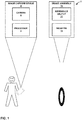
- FIG. 1 is a conceptual diagram illustrating an example image capture device 4 configured to measure a wear pin 14 of a brake assembly 10, in accordance with one or more techniques of the current disclosure.
- Brake assembly 10 may be a brake assembly for a wheel in an aircraft.
- brake assembly 10 includes reference object 12 and wear pin 14.
- brake assembly 10 includes other objects not pictured in FIG. 1 .
- brake assembly 10 may further include one or more rotating discs (rotors), one or more stationary discs (stators), an end plate, and a pressure plate. These elements may be made of a carbon-metallic alloy, and may be referred to as a whole as the disc stack or heat pack.
- the stators may be attached to a torque tube that is bolted to the aircraft landing gear assembly.
- the rotors engage the wheel, with notches in the rotors fitting keys on the interior of a wheel hub.
- a wheel may turn on a wheel bearing, with the rotors spinning between the brake stators.
- Brake piston retraction springs maintain sufficient clearance between the rotors and the stators to permit the wheels to turn freely.
- Hydraulic actuating pistons may be built in the brake housing. When the brakes are activated, hydraulic pressure is increased within the pistons, moving them outward from the housing compressing the pressure plate, and reducing the clearance between the rotors and stators. The surfaces of the rotors and stators are pressed against each other, producing friction that slows the rotating wheel. While this is one example of brake assembly 10, other brake assemblies that use a wear pin, such as wear pin 14, may be used with techniques of the current disclosure.
- Brake assembly 10 may include wear pin 14.
- a wear pin may be present for each wheel.
- Wear pin 14 may be a pin that extends from the pressure plate through the housing, protruding from the brake assembly. The amount of pin protrusion by wear pin 14 is indicative of the combined thickness of the rotor and stator discs. Parking brake pressure may be applied to accurately read wear pin length.
- the brake assembly may need to be replaced.
- wear pin 14 does not protrude from the housing more than a designated minimum length, such as 0.64 cm (0.25 inches), the brake assembly may need to be replaced. Therefore, accurately measuring the length of wear pin 14 is important to the safe operation of an aircraft. Techniques of this disclosure describe measuring a wear pin. However, it should be appreciated that measuring wear pin 14 may include measuring the entirety of wear pin 14 or measuring only a portion of wear pin 14, such as a visible portion of wear pin 14.
- Reference object 12 of brake assembly 10 may be any portion of brake assembly 10 that may be captured in the same image as wear pin 14 and has a fixed length regardless of the wear or life expectancy of brake assembly 10. In other words, it can be any object in brake assembly 10 for which a dimension of said object is known. Reference object 12 may also be a group of objects separated by a known distance. For instance, reference object 12 may be a housing or a bracket that holds wear pin 14.
- Image capture device 4 may be used to execute techniques of this disclosure.
- Image capture device 4 may be any device capable of capturing an image and either capable of performing analysis on the image or capable of sending the image to a remote server capable of performing analysis on the image.
- image capture device 4 may be a mobile phone.
- image capture device 4 may be a tablet computer, a personal digital assistant (PDA), a laptop computer, a portable gaming device, a portable media player, an e-book reader, a watch, a television platform, a digital camera, or another type of computing device.
- PDA personal digital assistant
- image capture device 4 may include camera 6 configured to capture an input image.
- Camera 6 may be an optical instrument that records images that can be stored directly, transmitted to a remote server, or both.
- Camera 6 may be configured to capture still images or moving images.
- camera 6 may further be configured to select a single frame from the set of frames captured in the moving image to use as the input image for the purpose of techniques of the current disclosure.
- processors 8 may implement functionality and/or execute instructions within image capture device 4.
- processor 8 on image capture device 4 may receive and execute instructions stored by various storage devices that execute the functionality of various modules stored in the storage devices. These instructions executed by processor 8 may cause image capture device 4 to store information within the storage devices during program execution.
- Processor 8 may execute instructions of the modules to cause camera 6 of image capture device 4 to obtain an input image of brake assembly 10 and wear pin 14.
- Processor 8 may then use techniques of this disclosure to measure wear pin 14.
- processor 8 may also be configured to transmit the input image to a remote server that will perform techniques described herein to measure wear pin 14.
- image capture device 4 may obtain an input image of a portion of brake assembly 10.
- the input image includes wear pin 14 and reference object 12.
- Reference object 12 has a known dimension that is known by image capture device 4.
- the known dimension of reference object 12 may be provided by an external input, such as one or more of a specification sheet, a computer aided design, an engineering diagram, or a database of known dimensions.
- reference object 12 may comprise a bracket configured to hold wear pin 14.
- the bracket may be a typical bracket holding wear pin 14 and have a length of 3.71 cm (1.46 inches).
- reference object 12 may be any object in brake assembly 10 having a fixed or known length, and the length of reference object 12 may be any length suitable for the function of reference object 12 within brake assembly 10.
- a system could use multiple reference objects. In addition to using length, the system could use the 2D area of a reference object.
- image capture device 4 may obtain the input image by capturing the input image using camera 6.
- the reference object may be a bolt in the brake assembly, a distance between two or more bolts near the bracket, or a piston shaft.
- this disclosure may reference the "length" of reference object 12 or wear pin 14, it could be contemplated that length refers to a measurement of distance from a starting point to an ending point. Therefore, the measurement could actually be a length, a width, or a measurement of any portion of the object being measured.
- Processor 8 may determine an image dimension of reference object 12 based on the input image.
- the dimension of reference object 12 may be any of a length, a width, a 2D area, a distance between two objects, or any other characteristic that may be measured using techniques described herein.
- reference object 12 has a known length.
- processor 8 can determine a measurement ratio for the input image. In other words, processor 8 can determine how many centimetres each pixel represents. For example, if reference object 12 is measured to be 200 pixels, and the reference object is known to have a length of 3.71 cm (1.46 inches), then processor 8 can determine that each pixel represents 0.0185 cm (0.0073 inches).
- This ratio may be used for other measurements taken based on the input image, including the measurement of the wear pin.
- the reference object may have approximately the same depth in the scene as the pin so that the conversion of pixels to real-world units derived from the reference object also applies to the pin. Determining the image dimension of reference object 12 is further discussed in regards to FIGS. 2-3J . While this disclosure references the image length of an object being in pixels, any unit of measurement for length can be used for the image length value, such as inches, centimeters, or points.
- Processor 8 may further determine an image dimension of wear pin 14 based on the input image.
- the dimension of wear pin 14 may be any of a length, a width, a 2D area, or any other characteristic that may be measured using techniques described herein.
- Processor 8 may also determine an estimated measurement of the dimension of wear pin 14. In this determination, processor 8 may use the image dimension of wear pin 14, the image dimension of reference object 12, and the actual, known length of reference object 12. In general, the measurement ratio determined above can be used in conjunction with the image dimension of the wear pin to determine an estimated measurement of the dimension of wear pin 14.
- processor 8 may determine that wear pin 14 has an estimated measurement of the dimension of 1.85 cm (0.73 inches).
- estimated measurement refers to the measured value gathered using techniques described herein.
- the estimated measurement could be the precise, actual dimension of wear pin 14.
- the estimated measurement could have an error that causes the estimated measurement to be longer or shorter than the actual dimension of wear pin 14.
- the term estimated measurement is the calculated measurement resulting from performing techniques described herein.
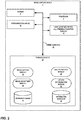
- FIG. 2 is a block diagram illustrating a more detailed example of an image capture device configured to measure a wear pin of a brake assembly, in accordance with one or more techniques of the current disclosure and within the context of FIG. 1 .
- FIG. 2 illustrates only one particular example of image capture device 4, and many other examples of image capture device 4 may be used in other instances and may include a subset of the components included in example image capture device 4 or may include additional components not shown in FIG. 2 .
- Image capture device 4 may include additional components that, for clarity, are not shown in FIG. 2 .
- image capture device 4 may include a battery to provide power to the components of image capture device 4.
- the components of image capture device 4 shown in FIG. 2 may not be necessary in every example of image capture device 4.
- image capture device 4 may not include communication unit 16.
- image capture device 4 includes user interface device 18 (e.g. a presence-sensitive display), one or more processors 8, one or more communication units 16, and one or more storage devices 22.
- Storage devices 22 of image capture device 4 also include image capture module 24, image adjustment module 26, quality control module 28, and length determination module 30.
- Storage devices 22 may also include database of reference images 32 and information database 34, among other things.
- Communication channels 20 may interconnect each of the components 6, 8, 16, 18, 22, 24, 26, 28, 30, 32 and 34 for inter-component communications (physically, communicatively, and/or operatively).
- communication channels 20 may include a system bus, a network connection, an interprocess communication data structure, or any other construct for communicating data.
- One or more communication units 16 of image capture device 4 may communicate with external devices via one or more networks by transmitting and/or receiving network signals on the one or more networks.
- image capture device 4 may use communication unit 16 to transmit and/or receive radio signals on a radio network such as a cellular radio network.
- communication units 16 may transmit and/or receive satellite signals on a satellite network such as a GPS network.
- Examples of communication unit 16 include a network interface card (e.g. such as an Ethernet card), an optical transceiver, a radio frequency transceiver, a GPS receiver, or any other type of device that may send and/or receive information.
- Other examples of communication units 16 may include Bluetooth®, GPS, 3G, 4G, and Wi-Fi® radios found in mobile devices as well as Universal Serial Bus (USB) controllers.
- USB Universal Serial Bus
- user interface device 18 of image capture device 4 may include functionality of various input devices and/or output devices.
- user interface device 18 provides output to a user using tactile, audio, or video stimuli using a display device, such as a cathode ray tube (CRT) monitor, liquid crystal display (LCD), or any other type of device for generating visual output.
- a display device such as a cathode ray tube (CRT) monitor, liquid crystal display (LCD), or any other type of device for generating visual output.
- user interface device 18 may also provide a method of entering input to image capture device 4, such as presence-sensitive screen, touch-sensitive screen, etc.
- One or more storage devices 22 within image capture device 4 may store information for processing during operation of image capture device 4.
- storage device 22 is a temporary memory, meaning that a primary purpose of storage device 22 is not long-term storage.
- Storage devices 22 on image capture device 4 may configured for short-term storage of information as volatile memory and therefore not retain stored contents if powered off. Examples of volatile memories include random access memories (RAM), dynamic random access memories (DRAM), static random access memories (SRAM), and other forms of volatile memories known in the art.
- RAM random access memories
- DRAM dynamic random access memories
- SRAM static random access memories
- Storage devices 22 may be configured to store larger amounts of information than volatile memory.
- Storage devices 22 may further be configured for long-term storage of information as non-volatile memory space and retain information after power on/off cycles. Examples of non-volatile memories include magnetic hard discs, optical discs, floppy discs, flash memories, or forms of electrically programmable memories (EPROM) or electrically erasable and programmable (EEPROM) memories.
- Storage devices 22 may store program instructions and/or data associated with image capture module 24, image adjustment module 26, quality control module 28, and length determination module 30. Storage devices 22 may also store program instructions and/or data associated with reference images 32 or information database 34, among other things.
- processors 8 may implement functionality and/or execute instructions within image capture device 4.
- processors 8 on image capture device 4 may receive and execute instructions stored by storage devices 22 that execute the functionality of image capture module 24, image adjustment module 26, quality control module 28, and length determination module 30. These instructions executed by processors 8 may cause image capture device 4 to store information, within storage devices 22 during program execution.
- Processors 8 may execute instructions of image capture module 24, image adjustment module 26, quality control module 28, and length determination module 30 to determine an estimated measurement of the dimension of wear pin 14 based on an input image.
- items in storage device 22, such as image capture module 24, image adjustment module 26, quality control module 28, and length determination module 30, may be operable by processors 8 to perform various actions, including determining an estimated measurement of the dimension of wear pin 14 based on an image dimension of wear pin 14, an image dimension of reference object 12, and a known dimension of reference object 12 via an obtained input image, as shown in FIG. 1 .
- processor 8 may execute image capture module 24 to obtain an input image of a portion of the brake assembly (e.g. brake assembly 10 of FIG. 1 ).
- the input image includes a wear pin (e.g. wear pin 14 of FIG. 1 ) and a reference object (e.g. reference object 12 of FIG. 1 ).
- Reference object 12 has an actual, known length.
- reference object 12 may comprise a bracket configured to hold wear pin 14.
- the bracket may be a typical bracket holding wear pin 14 and have a length of 3.71 cm (1.46 inches). While this is given as an example, reference object 12 may be any object in brake assembly 10 having a fixed or known length, and the length of reference object 12 may be any length suitable for the function of reference object 12 within brake assembly 10.
- image capture module 24 may capture the input image using camera 6. In some further examples, image capture module 24 may output, on a display operatively connected to camera 6 (e.g. user interface device 18), a prompt to capture the input image. Further, in some examples, image capture module 24 may output, on a preview display operatively connected to the camera (e.g. user interface device 18), a graphical outline overlaid on a preview of the input image. In some examples, the graphical outline may be shaped in the form of a rectangle, a square, a circle, a wear-pin shaped outline, a reference object-shaped outline, or any other suitable shape.
- the graphical outline may be displayed such that the portion of brake assembly 10 in the input image should fall within the graphical outline when the input image is captured, meaning that the graphical outline is an optimal area for the user to place reference object 12 and wear pin 14 when capturing the input image.
- the reference object may be a bolt in the brake assembly, a distance between two or more bolts near the bracket, or a piston shaft.
- communication unit 16 may send the input image to a server.
- a computing device operatively connected to the server may be configured to utilize techniques described herein to determine the image dimension of the reference object, the image dimension of the wear pin, and the estimated measurement of the dimension of the wear pin.
- image capture device 4 may only be configured to capture the input image and send the input image to a remote server that is configured to analyze the input image using techniques of this disclosure. While this disclosure references the image length of an object being in pixels, any unit of measurement for length can be used for the image length value, such as inches, centimeters, or points.
- processor 8 may execute image adjustment module 26 to edit the input image such that the wear pin is in the optimal state (e.g. optimal position, contrast, color, etc.) for processor 8 to determine the length of wear pin 14. For example, processor 8 may execute image adjustment module 26 to rotate the input image such that wear pin 14 is approximately horizontal in the rotated input image. In some examples, in rotating the input image, processor 8 may execute image adjustment module 26 to perform edge detection analysis on the input image to detect one or more near-vertical edges of brake assembly 10 and rotate the input image such that the detected edges of brake assembly 10 are approximately vertical. In other examples, image adjustment module 26 may rotate the input image such that wear pin 14 is approximately vertical in the rotated input image.
- image adjustment module 26 may rotate the input image such that wear pin 14 is approximately vertical in the rotated input image.
- processor 8 may execute image adjustment module 26 to perform edge detection analysis on the input image to detect one or more near-horizontal edges of brake assembly 10 and rotate the input image such that the detected edges of brake assembly 10 are approximately horizontal.
- wear pin 14 is approximately horizontal after the rotation and will be measured from left to right. However, in other examples, wear pin 14 is approximately horizontal and will be measured from right to left.
- processor 8 may execute image adjustment module 26 to convert the input image to a greyscale image.
- image adjustment module 26 may allow for faster transmissions due to the smaller file size.
- wear pin 14 and reference object 12 overlap one another and are distinguishable by what shade of grey each object is.
- wear pin 14 tends to be a dark color
- reference object 12 tends to be a light color, though some examples could have a light color wear pin and a dark color reference object. This means that a greyscale image does not impact the ability to discern wear pin 14 from the reference object during the execution of techniques of this disclosure.
- the conversion to greyscale may also accelerate image analysis techniques. For example, many image analysis techniques only operate on single-channel images.
- processor 8 may execute image adjustment module 26 to apply a smoothing algorithm to the input image.
- the smoothing algorithm may be a bilateral filter.
- a bilateral filter is a non-linear, edge-preserving, noise-reducing smoothing filter for images. By preserving the edges in the image, the length of wear pin 14 will not be altered due to edits made to the input image. Instead, the bilateral filter will merely smooth the image such that it is easier to discern wear pin 14 from reference object 12. As discussed above, wear pin 14 and reference object 12 may overlap one another and may be distinguishable by color or intensity. By applying the bilateral filter, processor 8 may be able to more effectively determine where the edges of wear pin 14 and reference object 12 are in the input image, allowing for more precise measurements.
- processor 8 may execute image adjustment module 26 to apply an equalization algorithm to the input image based on one or more lighting conditions.
- the lighting conditions of the environment in which brake assembly 10 is present may greatly affect the contrast of an image taken in that environment.
- the ability of processor 8 to discern wear pin 14 from reference object 12 will greatly affect the precision of a measurement for wear pin 14. Therefore, improving the contrast level of the input image may allow for greater precision in measurements.
- image adjustment module 26 may increase the contrast of the input image if the lighting conditions are too dark. Further, image adjustment module 26 may decrease the contrast of the input image if the lighting conditions are too bright. The equalization allows all images to appear similar, regardless of their original lighting conditions or contrast.
- Processor 8 may execute length determination module 30 to determine, based on the input image, an image dimension of the reference object.
- the dimension of reference object 12 may be any of a length, a width, a 2D area, a distance between two objects, or any other characteristic that may be measured using techniques described herein.
- processor 8 may execute length determination module 30 to detecting a first point on the reference object and a second point on the reference object in the input image.
- the first point and the second point may be on a perimeter of the reference object and may be on opposite extremes of the reference object.
- the first point may not intersect with the second point, meaning that the first point and the second point are two discrete, non-connecting, approximately parallel line segments.
- first point and the second point may be opposite edges of reference object 12.
- reference object 12 is a trapezoidal bracket holding wear pin 14
- first point and the second point may be the two opposite bases of the trapezoidal bracket.
- Processor 8 may further execute length determination module 30 to determine a number of pixels in a horizontal row that separates the first point and the second point. Further, processor 8 may execute length determination module 30 to determine a length per pixel ratio for the input image based on the number of pixels that separates the first point and the second point and the known dimension of the reference object.
- the known dimension of reference object 12 may be provided by an external input, such as one or more of a specification sheet, a computer aided design, an engineering diagram, or a database of known dimensions.
- processor 8 can determine that each pixel represents 0.0185 cm (0.0073 inches). This ratio may be used for other measurements taken based on the input image, including the measurement of the wear pin.
- the first point and the second point may be determined using an edge detection algorithm, such as a Sobel filter.
- processor 8 may first identify reference object 12. To do so, processor 8 may execute length determination module 30 to compare one or more portions of the input image to a template of reference object 12. Such a template of reference object 12 may be stored in reference images database 32 of storage devices 22. Further, processor 8 may execute length determination module 30 to determine, based on the one or more comparisons, a portion of the input image that most closely matches the template of reference object 12 and detect the first point and the second point based on the portion of the input image that most closely matches the template of reference object 12.
- Processor 8 may execute length determination module 30 to determine, based on the input image, an image dimension of wear pin 14.
- the dimension of wear pin 14 may be any of a length, a width, a 2D area, or any other characteristic that may be measured using techniques described herein.
- processor 8 may execute length determination module 30 to detect a location of wear pin 14.
- Processor 8 may execute length determination module 30 to detect a first edge of the wear pin in the input image.
- the first edge represents a fixed end of the wear pin in a bracket assembly.
- the first edge may be determined using an edge detection algorithm, such as a Sobel filter.
- processor 8 may execute length determination module 30 to identify one or more line segments near wear pin 14 starting at the first edge.
- Processor 8 may further execute length determination module 30 to identify one or more clusters of the one or more line segments and identify a cluster of the one or more clusters that is coincident with wear pin 14. Processor 8 may further execute length determination module 30 to merge each line segment in the cluster coincident with wear pin 14 and determine a number of pixels corresponding to the length of the merged line segment. In some examples, the identification of one or more horizontal line segments may be accomplished through the application of an edge detection kernel to detect approximately horizontal edges, a determination of pixels with responses above a threshold as horizontal edges, and applying a Hough line transform to each horizontal edge. Processor 8 may execute length determination module 30 to determine a number of pixels in the largest cluster.
- Processor 8 may execute length determination module 30 to determine, based on the image dimension of the reference object, the image dimension of the wear pin, and the known dimension of the reference object, an estimated measurement of the dimension of the wear pin.
- processor 8 may output, on a display operatively connected to image capture device 4 (e.g. user interface device 18) and based on the image dimension of wear pin 14 and the determined estimated measurement of the dimension of wear pin 14, a graphical representation of the determined estimated measurement of the dimension of the wear pin.
- the graphical representation of the determined estimated measurement of the dimension of wear pin 14 may be a line segment displayed overlaid on top of an approximate location of wear pin 14 in the input image.
- processor 8 may output, on user interface device 18, a confirmation prompt that the graphical representation is a suitable representation of the determined estimated measurement of the dimension of wear pin 14. This may allow a user to have more visual control of the measurement. If certain conditions in the input image cause the techniques of this disclosure to return an erroneous measurement, the user may be able to rectify this before submitting the measurement by seeing the graphical representation overlaid on top of the discerned and measured wear pin 14.
- processor 8 may execute length determination module 30 to determine, based on the determined estimated measurement of the dimension of wear pin 14, an estimated remaining life expectancy for wear pin 14. This would provide the user an indication of when wear pin 14 and brake assembly 10 will be in need of repair.
- the estimated remaining life expectancy is an estimated time until replacement for the wear pin.
- the estimated remaining life expectancy is an estimated number of uses until replacement.
- the life expectancy of wear pin 14 may be different depending on the type of vehicle for which wear pin 14 is being measured. For instance, if the vehicle is a large, passenger aircraft, a wear pin length of 5 cm (2 inches) may have a shorter remaining life expectancy than a wear pin length of 5 cm (2 inches) for a vehicle that is a small, private airplane. Therefore, processor 8 may execute length determination module 30 to determine the estimated remaining life expectancy for the wear pin further based on a vehicle type.
- image capture module 24 may further obtain one or more subsequent input images (such as via camera 6).
- the one or more subsequent input images may identify a vehicle associated with brake assembly 10.
- Processor 8 may execute length determination module 30 to retrieve one or more stored dimensions of wear pin 14 and save the estimated measurement of the dimension as a most recent stored dimension for wear pin 14 of the vehicle associated with brake assembly 10. This stored dimension may be saved in information database 34 of image capture device 4.
- information database 34 may be stored on the remote server.
- processor 8 may further determine an estimated life expectancy of wear pin 14 based on a rate of change.
- Techniques may further include quality analysis of input images based on various quality estimation parameters derived throughout the measurement process. For instance, a user who photographs a brake wear pin (or any similar object) with the intent of measuring the length is unaware of how the image's quality affects the measurement. As the images are captured using a handheld device, they may be of a degraded quality due to focus or motion blur. Similarly, the image may be over/under exposed. The image may be required to meet certain quality checks in order for the program to provide a measurement. That is, in some cases, the image may be so poor that obtaining a decent measurement is difficult, and the image should be thrown away. When the program is able to measure a pin, the user may benefit from receiving a confidence score or error interval to understand the probable accuracy.
- the image may represent the scene accurately
- the scene may contain elements that are troublesome for the pin-measuring algorithm, such as dirt/grease/grit near the pin or a sub-optimal camera pose. These unforeseen elements could cause the pin-measuring algorithm to partially fail. Therefore, software logic may be included to decide when an image is too poor to provide any measurement (i.e. no confidence), and give the user an expected error interval otherwise.
- processor 8 may execute quality control module 28 to determine a quality estimation parameter for the input image. Further, processor 8 may execute quality control module 28 to determine whether the quality estimation parameter is within an acceptable range.
- the term "acceptable range" can be any pre-defined or dynamically defined range of values for which an input image is deemed to be of acceptable quality.
- processor 8 may execute quality control module 28 to send an indication to a user. In such examples, processor 8 may prompt a user to re-capture the input image using different camera extrinsic properties, such as camera position, camera motion, flash, or other camera settings.
- processor 8 may prompt the user to capture one or more subsequent input images of the portion of the brake assembly with different camera extrinsic properties. If a higher quality input image is captured, techniques described herein may be performed on that input image. However, in response to the quality estimation parameter being within the acceptable range, processor 8 may execute length determination module 30 to determine the estimated measurement of the dimension of wear pin 14 based on the input image, as described in detail above. Processor 8 may further execute quality control module 28 to dynamically update the acceptable range based on one or more environmental conditions, such as lighting or presence of foreign substances (e.g. grease, sludge, scrapes, paint, etc.). In some examples, the quality estimation parameter is determined by the same device that captures the input image (i.e. image capture device 4). In other examples, the quality estimation parameter is determined by a remote server that receives the input image from image capture device 4.
- the quality estimation parameter is determined by the same device that captures the input image (i.e. image capture device 4). In other examples, the quality estimation parameter is determined by a remote
- the quality estimation parameter may be determined based on a contrast of the input image.
- determining whether the quality estimation parameter is within the acceptable range may include processor 8 executing quality control module 28 to convert the input image to a greyscale image.
- Processor 8 may also execute quality control module 28 to determine an average greyscale value in the greyscale image and to determine a standard deviation of greyscale values in the greyscale image.
- Processor 8 may then determine that the quality estimation parameter is not within the acceptable range if the standard deviation of greyscale values does not fall within a lower limit and an upper limit.
- processor 8 may determine that the quality estimation parameter is within the acceptable range if the standard deviation of greyscale values falls within the lower limit and the upper limit.
- processor 8 and length determination module 30 may not be capable of discerning wear pin 14 and reference object 12 for the purposes of measuring the objects in accordance with techniques described herein. Therefore, measuring the contrast before measuring the objects may save time and processing power when the input image does not meet the requisite quality.
- the quality estimation parameter may be determined based on a brightness of the input image.
- determining whether the quality estimation parameter is within the acceptable range may include processor 8 executing quality control module 28 to convert the input image to a greyscale image.
- Processor 8 may also execute quality control module 28 to determine an average greyscale value in the greyscale image.
- Processor 8 may then determine that the quality estimation parameter is not within the acceptable range if the average greyscale value does not fall within a lower limit and an upper limit.
- processor 8 may determine that the quality estimation parameter is within the acceptable range if the average greyscale value falls within the lower limit and the upper limit.
- processor 8 and length determination module 30 may not be capable of discerning wear pin 14 and reference object 12 for the purposes of measuring the objects in accordance with techniques described herein. Therefore, measuring the brightness before measuring the objects may save time and processing power when the input image does not meet the requisite quality.
- the quality estimation parameter may be determined based on a blurriness of the input image.
- determining whether the quality estimation parameter is within the acceptable range may include dividing the input image into a plurality of windows. Each window may overlap a portion of each window horizontally adjacent to the respective window.
- Processor 8 may also execute quality control module 28 to determine a blurriness parameter for each window of the plurality of windows based on a magnitude of a Fast Fourier transform algorithm applied over a percentile of available spatial frequencies.
- Processor 8 may execute quality control module 28 to determine the quality estimation parameter for the input image as a weighted function of the blurriness parameter for each window.
- the weighted function of the blurriness parameters may be a mean, a minimum function, or a maximum function.
- the weighted function comprises a weight associated with the blurriness parameter for each window, wherein the weight associated with the blurriness parameter for a window of the plurality of windows that contains the wear pin is a non-zero value, and wherein the weight associated with the blurriness parameter for each window of the plurality of windows that does not contain the wear pin is a zero value.
- Processor 8 may determine that the quality estimation parameter is not within the acceptable range if the quality estimation parameter is below a lower limit of blurriness.
- processor 8 may determine that the quality estimation parameter is within the acceptable range if the quality estimation parameter is above the lower limit of blurriness.
- the input image may be divided into any number of windows, including one of nine windows, sixteen windows, or twenty-five windows.
- the blurriness parameter for each window is an average of the blurriness for each pixel in the respective window.
- the blurriness parameter for each window is a minimum blurriness for each pixel in the respective window. If the input image is too blurry, processor 8 and length determination module 30 may not be capable of discerning wear pin 14 and reference object 12 for the purposes of measuring the objects in accordance with techniques described herein. Therefore, measuring the blurriness before measuring the objects may save time and processing power when the input image does not meet the requisite quality.
- processor 8 may execute quality control module 28 to determine a confidence measurement of the estimated measurement of the dimension of the wear pin based on the quality estimation parameter. In some further examples, processor 8 may execute quality control module 28 to prompt a user, via user interface device 18, to re-capture the input image if the confidence measurement is below a threshold confidence level. Processor 8 may further execute quality control module 28 to present an error boundary, via user interface device 18, based on the quality estimation parameter. This may further assist a user in determining whether to accept the measurement provided by image capture device 4 or to re-capture the image using camera 6.
- FIGS. 3A-3J are example input images of a brake assembly at various points throughout the process of measuring a wear pin, in accordance with one or more techniques of the current disclosure.
- the input images depicted by FIGS. 3A-3J should be seen as example images only. Each image along these various points of the process of measuring a wear pin may be unique. Further, some steps depicted by FIGS. 3A-3J may not be taken in executing instances of the techniques described herein. For instance, one example instance of the techniques described in the current disclosure may not convert the input image to a greyscale image. Further, steps not depicted by FIGS. 3A-3J may be performed during an instance of the techniques described herein. For instance, processor 8 may output a graphical outline overlaid on a preview of the input image, with the graphical outline being displayed such that the portion of brake assembly 10 in the input image should fall within the graphical outline when the input image is captured.
- Techniques may further include quality analysis of input images based on various quality estimation parameters derived throughout the measurement process. For instance, a user who photographs a brake wear pin (or any similar object) with the intent of measuring the length is unaware of how the image's quality affects the measurement. As the images are captured using a handheld device, they may be of a degraded quality due to focus or motion blur. Similarly, the image may be over/under exposed. The image may be required to meet certain quality checks in order for the program to provide a measurement. That is, in some cases, the image may be so poor that obtaining a decent measurement is difficult, and the image should be thrown away. When the program is able to measure a pin, the user may benefit from receiving a confidence score or error interval to understand the probable accuracy.
- the image may represent the scene accurately
- the scene may contain elements that are troublesome for the pin-measuring algorithm, such as dirt/grease/grit near the pin or a sub-optimal camera pose. These unforeseen elements could cause the pin-measuring algorithm to partially fail. Therefore, software logic may be included to decide when an image is too poor to provide any measurement (i.e. no confidence), and give the user an expected error interval otherwise.
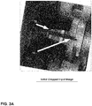
- FIG. 3A is an example input image as it is taken by an image capture device.
- wear pin 14 and reference object 12 are shown in the image after it has been obtained by image capture device 4. This will be the general input image which will be used to measure wear pin 14.
- processor 8 may execute image capture module 24 to may obtain an input image of a portion of the brake assembly (e.g. brake assembly 10 of FIG. 1 ).
- the input image includes a wear pin (e.g. wear pin 14 of FIG. 1 ) and a reference object (e.g. reference object 12 of FIG. 1 ).
- Reference object 12 has an actual, known length.
- reference object 12 may comprise a bracket configured to hold wear pin 14.
- the bracket may be a typical bracket holding wear pin 14 and have a length of 3.71 cm (1.46 inches). While this is given as an example, reference object 12 may be any object in brake assembly 10 having a fixed or known length, and the length of reference object 12 may be any length suitable for the function of reference object 12 within brake assembly 10.
- image capture module 24 may capture the input image using camera 6. In some further examples, image capture module 24 may output, on a display operatively connected to camera 6 (e.g. user interface device 18), a prompt to capture the input image. Further, in some examples, image capture module 24 may output, on a preview display operatively connected to the camera (e.g. user interface device 18), a graphical outline overlaid on a preview of the input image. The graphical outline may be displayed such that the portion of brake assembly 10 in the input image should fall within the graphical outline when the input image is captured. In other examples, the reference object may be a bolt in the brake assembly, a distance between two or more bolts near the bracket, or a piston shaft.
- communication unit 16 may send the input image to a server.
- a computing device operatively connected to the server may configured to utilize techniques described herein to determine the image dimension of the reference object, the image dimension of the wear pin, and the estimated measurement of the dimension of the wear pin.
- image capture device 4 may only be configured to capture the input image and send the input image to a remote server that is configured to analyze the input image using techniques of this disclosure.
- processor 8 may execute quality control module 28 to determine a quality estimation parameter for the input image. Further, processor 8 may execute quality control module 28 to determine whether the quality estimation parameter is within an acceptable range. In response to the quality estimation parameter not being within the acceptable range, processor 8 may execute quality control module 28 to send an indication to a user. In such examples, processor 8 may prompt a user to re-capture the input image using different camera extrinsic properties, such as camera position, camera motion, flash, or other camera settings. In other examples, processor 8 may prompt the user to capture one or more subsequent input images of the portion of the brake assembly with different camera extrinsic properties. If a higher quality input image is captured, techniques described herein may be performed on that input image.
- processor 8 may execute length determination module 30 to determine the estimated measurement of the dimension of wear pin 14 based on the input image, as described in detail above.
- Processor 8 may further execute quality control module 28 to dynamically update the acceptable range based on one or more environmental conditions, such as lighting or presence of foreign substances (e.g. grease, sludge, scrapes, paint, etc.).
- the quality estimation parameter is determined by the same device that captures the input image (i.e. image capture device 4).
- the quality estimation parameter is determined by a remote server that receives the input image from image capture device 4.
- the quality estimation parameter may be determined based on a blurriness of the input image.
- determining whether the quality estimation parameter is within the acceptable range may include dividing the input image into a plurality of windows. Each window may overlap a portion of each window horizontally adjacent to the respective window.
- Processor 8 may also execute quality control module 28 to determine a blurriness parameter for each window of the plurality of windows based on a magnitude of a Fast Fourier transform algorithm applied over a percentile of available spatial frequencies.
- Processor 8 may execute quality control module 28 to determine the quality estimation parameter for the input image as a weighted function of the blurriness parameter for each window.
- the weighted function of the blurriness parameters may be a mean, a minimum function, or a maximum function.
- the weighted function comprises a weight associated with the blurriness parameter each window, wherein the weight associated with the blurriness parameter for a window of the plurality of windows that contains the wear pin is a non-zero value, and wherein the weight associated with the blurriness parameter for each window of the plurality of windows that does not contain the wear pin is a zero value.
- Processor 8 may determine that the quality estimation parameter is not within the acceptable range if the quality estimation parameter is below a lower limit of blurriness.
- processor 8 may determine that the quality estimation parameter is within the acceptable range if the quality estimation parameter is above the lower limit of blurriness.
- the input image may be divided into any number of windows, including one of nine windows, sixteen windows, or twenty-five windows.
- the blurriness parameter for each window is an average of the blurriness for each pixel in the respective window.
- the blurriness parameter for each window is a minimum blurriness for each pixel in the respective window. If the input image is too blurry, processor 8 and length determination module 30 may not be capable of discerning wear pin 14 and reference object 12 for the purposes of measuring the objects in accordance with techniques described herein. Therefore, measuring the blurriness before measuring the objects may save time and processing power when the input image does not meet the requisite quality.
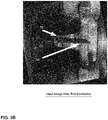
- FIG. 3B is an example input image after roll correction has been performed.
- Processor 8 may rotate the image in order to bring wear pin 14 as close to a horizontal line or a vertical line as possible.
- wear pin 14 is now approximately horizontal.
- approximately horizontal means that the wear pin 14 is within ⁇ 5 degrees of horizontal.
- processor 8 may execute image adjustment module 26 to rotate the input image such that wear pin 14 is approximately horizontal in the rotated input image.
- processor 8 may execute image adjustment module 26 to perform edge detection analysis on the input image to detect one or more edges of wear pin 14 and rotate the input image such that the detected edges of wear pin 14 are approximately vertical.
- image adjustment module 26 may rotate the input image such that wear pin 14 is approximately vertical in the rotated input image.
- processor 8 may execute image adjustment module 26 to perform edge detection analysis on the input image to detect one or more edges of wear pin 14 and rotate the input image such that the detected edges of wear pin 14 are approximately horizontal.
- FIG. 3C is an example input image after the input image has been converted to a greyscale version of the input image.
- processor 8 may execute image adjustment module 26 to convert the input image to a greyscale image.
- image adjustment module 26 By converting the input image to a greyscale image, the storage space needed to hold the file in a computing device may be smaller.
- a greyscale image may allow for faster transmissions due to the smaller file size.
- wear pin 14 and reference object 12 overlap one another and are distinguishable by what shade of grey each object is.
- wear pin 14 tends to be a dark color
- reference object 12 tends to be a light color
- wear pin 14 tends to be a dark color
- reference object 12 tends to be a light color
- a greyscale image does not impact the ability to discern wear pin 14 from the reference object during the execution of techniques of this disclosure.
- the quality estimation parameter may be determined based on a contrast of the input image.
- determining whether the quality estimation parameter is within the acceptable range may include processor 8 executing quality control module 28 to convert the input image to a greyscale image.
- Processor 8 may also execute quality control module 28 to determine an average greyscale value in the greyscale image and to determine a standard deviation of greyscale values in the greyscale image.
- Processor 8 may then determine that the quality estimation parameter is not within the acceptable range if the standard deviation of greyscale values does not fall within a lower limit and an upper limit.
- processor 8 may determine that the quality estimation parameter is within the acceptable range if the standard deviation of greyscale values falls within the lower limit and the upper limit.
- processor 8 and length determination module 30 may not be capable of discerning wear pin 14 and reference object 12 for the purposes of measuring the objects in accordance with techniques described herein. Therefore, measuring the contrast before measuring the objects may save time and processing power when the input image does not meet the requisite quality.
- the quality estimation parameter may be determined based on a brightness of the input image.
- determining whether the quality estimation parameter is within the acceptable range may include processor 8 executing quality control module 28 to convert the input image to a greyscale image.
- Processor 8 may also execute quality control module 28 to determine an average greyscale value in the greyscale image.
- Processor 8 may then determine that the quality estimation parameter is not within the acceptable range if the average greyscale value does not fall within a lower limit and an upper limit.
- processor 8 may determine that the quality estimation parameter is within the acceptable range if the average greyscale value falls within the lower limit and the upper limit.
- processor 8 and length determination module 30 may not be capable of discerning wear pin 14 and reference object 12 for the purposes of measuring the objects in accordance with techniques described herein. Therefore, measuring the brightness before measuring the objects may save time and processing power when the input image does not meet the requisite quality.
- FIG. 3D is an example input image after a smoothing algorithm has been applied to the input image.
- processor 8 may execute image adjustment module 26 to apply a smoothing algorithm to the input image.
- the smoothing algorithm may be a bilateral filter.
- a bilateral filter is a non-linear, edge-preserving, noise-reducing smoothing filter for images. By preserving the edges in the image, the length of wear pin 14 will not be altered due to edits made to the input image. Instead, the bilateral filter will merely smooth the image such that it is easier to discern wear pin 14 from reference object 12. As discussed above, wear pin 14 and reference object 12 may overlap one another and may be distinguishable by color. By applying the bilateral filter, processor 8 may be able to more effectively determine where the edges of wear pin 14 and reference object 12 are in the input image, allowing for more precise measurements.
- FIG. 3E is an example input image after performing equalization to the input image.
- processor 8 may execute image adjustment module 26 to apply an equalization algorithm to the input image based on one or more lighting conditions.
- the lighting conditions of the environment in which brake assembly 10 is present may greatly affect the contrast of an image taken in that environment.
- the ability of processor 8 to discern wear pin 14 from reference object 12 will greatly affect the precision of a measurement for wear pin 14. Therefore, improving the contrast level of the input image may allow for greater precision in measurements.
- image adjustment module 26 may increase the contrast of the input image if the lighting conditions are too dark. Further, image adjustment module 26 may decrease the contrast of the input image if the lighting conditions are too bright.
- FIG. 3F shows example templates that may be used when identifying portions of a brake assembly.
- processor 8 may compare portions of the input image to various templates of reference object 12 stored in reference images 32.
- FIG. 3F shows three different templates for reference object 12.
- various sizes and colors of reference object 12 and wear pin 14 may be stored.
- template image 13A shows a wider reference object 12 and a short wear pin 14.
- Template image 13B shows a slightly discolored reference object 12 and a short-medium length wear pin 14.
- Template image 13C shows a reference object 12 with less taper than the reference objects of 13A and 13B, as well as a long wear pin 14.
- processor 8 may determine an area of the input image that resembles one or more of the templates 13A-13C. Processor 8 may then determine an image dimension of reference object 12. For example, processor 8 may execute length determination module 30 to determine, based on the input image, an image dimension of the reference object.
- the dimension of reference object 12 may be any of a length, a width, a 2D area, a distance between two objects, or any other characteristic that may be measured using techniques described herein.
- processor 8 may execute length determination module 30 to detect a first point of the reference object and a second point of the reference object in the input image.
- the first point may not intersect with the second point, meaning that the first point and the second point are two discrete, non-connecting line segments.
- the first point and the second point may be opposite edges of reference object 12.
- reference object 12 is a trapezoidal bracket holding wear pin 14
- the first point and the second point may be the two opposite bases of the trapezoidal bracket.
- Processor 8 may further execute length determination module 30 to determine a number of pixels in a horizontal row that separates the first point and the second point. Further, processor 8 may execute length determination module 30 to determine a length per pixel ratio for the input image based on the number of pixels that separates the first point and the second point and the known dimension of the reference object.
- processor 8 can determine that each pixel represents0.0185 cm (0.0073 inches). This ratio may be used for other measurements taken based on the input image, including the measurement of the wear pin.
- the first point and the second point may be determined using an edge detection algorithm, such as a Sobel filter.
- processor 8 may execute length determination module 30 to compare one or more portions of the input image to a template of reference object 12.
- a template of reference object 12 may be stored in reference images database 32 of storage devices 22.
- processor 8 may execute length determination module 30 to determine, based on the one or more comparisons, a portion of the input image that most closely matches the template of reference object 12 and detect the first point and the second point based on the portion of the input image that most closely matches the template of reference object 12.
- FIG. 3G is further examples of different images used when measuring the reference object.
- FIG. 3H is an example input image after performing a cluster matching technique to identify a wear pin.
- processor 8 may determine a portion of the input image that most closely resembles wear pin 14. Using these techniques, processor 8 determines that cluster 15 shows a portion of the input image that closely resembles wear pin 14 in the templates 13A-13C.
- FIG. 3I are examples of using various line segments in order to identify the wear pin in the input image.
- processor 8 may detect edges of wear pin 14 and determine a line segment that substantially connects the first point and the second point. For example, processor 8 may use a Sobel filter and Hough transform to find these edges and segments.
- processor 8 may be able to use this portion of the input image to determine an image dimension of wear pin 14. For example, processor 8 may execute length determination module 30 to determine, based on the input image, an image dimension of wear pin 14.
- the dimension of wear pin 14 may be any of a length, a width, a 2D area, or any other characteristic that may be measured using techniques described herein.
- processor 8 may execute length determination module 30 to detect a location of wear pin 14.
- Processor 8 may execute length determination module 30 to detect a first edge of the wear pin in the input image. The first edge represents a fixed end of the wear pin in a bracket assembly. In some examples, the first edge may be determined using an edge detection algorithm, such as a Sobel filter.
- processor 8 may execute length determination module 30 to identify one or more line segments near wear pin 14 starting at the first edge.
- processor 8 may further execute length determination module 30 to identify one or more clusters of the one or more line segments and identify a cluster of the one or more clusters that is coincident with wear pin 14.
- Processor 8 may further execute length determination module 30 to merge each line segment in the cluster coincident with wear pin 14 and determine a number of pixels corresponding to the length of the merged line segment.
- the identification of one or more horizontal line segments may be accomplished through the application of an edge detection kernel to detect approximately horizontal edges, a determination of pixels with responses above a threshold as horizontal edges, and applying a Hough line transform to each horizontal edge.
- Processor 8 may execute length determination module 30 to determine a number of pixels in the largest cluster. In cases when the pin is short and contains relatively few pixels, other measures, such as the vertical centrality of each cluster and compactness, may help identify the pin. Though described above as determining horizontal line segments, techniques of this disclosure could also be utilized for a wear pin that is vertical in an input image.
- FIG. 3J is an example input image with an overlay of a measured length of a wear pin.
- processor 8 may determine an estimated measurement of the dimension of wear pin 14.
- processor 8 further outputs an overlay of the graphical representation of wear pin 14, along with the determined measurement.
- Processor 8 may output these graphics on user interface device 18.
- processor 8 may execute length determination module 30 to determine, based on the image dimension of the reference object, the image dimension of the wear pin, and the known dimension of the reference object, an estimated measurement of the dimension of the wear pin.
- processor 8 may output, on a display operatively connected to image capture device 4 (e.g. user interface device 18) and based on the image dimension of wear pin 14 and the determined estimated measurement of the dimension of wear pin 14, a graphical representation of the determined estimated measurement of the dimension of the wear pin.
- the graphical representation of the determined estimated measurement of the dimension of wear pin 14 may be a line segment displayed overlaid on top of an approximate location of wear pin 14 in the input image.
- processor 8 may output, on user interface device 18, a confirmation prompt that the graphical representation is a suitable representation of the determined estimated measurement of the dimension of wear pin 14. This may allow a user to have more visual control of the measurement. If certain conditions in the input image cause the techniques of this disclosure to return an erroneous measurement, the user may be able to rectify this before submitting the measurement by seeing the graphical representation overlaid on top of the discerned and measured wear pin 14.
- processor 8 may execute length determination module 30 to determine, based on the determined estimated measurement of the dimension of wear pin 14, an estimated remaining life expectancy for wear pin 14. This would provide the user an indication of when wear pin 14 and brake assembly 10 will be in need of repair.
- the estimated remaining life expectancy is an estimated time until replacement for the wear pin.
- the estimated remaining life expectancy is an estimated number of uses until replacement.
- the life expectancy of wear pin 14 may be different depending on the type of vehicle for which wear pin 14 is being measured. For instance, if the vehicle is a large, passenger aircraft, a wear pin length of 5 cm (2 inches) may have a shorter remaining life expectancy than a wear pin length of 5 cm (2 inches) for a vehicle that is a small, private airplane. Therefore, processor 8 may execute length determination module 30 to determine the estimated remaining life expectancy for the wear pin further based on a vehicle type.
- processor 8 may execute quality control module 28 to determine a confidence measurement of the estimated measurement of the dimension of the wear pin based on the quality estimation parameter. In some further examples, processor 8 may execute quality control module 28 to prompt a user, via user interface device 18, to re-capture the input image if the confidence measurement is below a threshold confidence level. Processor 8 may further execute quality control module 28 to present an error boundary, via user interface device 18, based on the quality estimation parameter. This may further assist a user in determining whether to accept the measurement provided by image capture device 4 or to re-capture the image using camera 6.
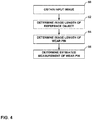
- FIG. 4 is a flow diagram illustrating an example process of measuring a wear pin in a brake assembly, in accordance with one or more techniques of the current disclosure.
- Techniques of this disclosure describe a system for automatically measuring wear pins based on an input image received from a computing device, such as a handheld device.
- This handheld device may measure wear pin length during regular intervals throughout the life of the brake.
- the device may record the aircraft's tail number, location, wheel position and capture an image of the wear pin for each brake location on the aircraft.
- the device may also enable the ability to capture other defects and brake-related failures.
- the data and images may then be uploaded to a central repository for analysis.
- Computer vision algorithms may measure the pin from images of the brake region.
- the server may then communicate results to the operators.
- a different version of the program may also perform all image processing locally on the handheld device and provide a real time pin length measurement to the user.
- processor 8 may execute image capture module 24 to obtain 60 an input image of a portion of the brake assembly (e.g. brake assembly 10 of FIG. 1 ).
- the input image includes a wear pin (e.g. wear pin 14 of FIG. 1 ) and a reference object (e.g. reference object 12 of FIG. 1 ).
- Reference object 12 has an actual, known length.
- reference object 12 may comprise a bracket configured to hold wear pin 14.
- the bracket may be a typical bracket holding wear pin 14 and have a length of 3.71 cm (1.46 inches). While this is given as an example, reference object 12 may be any object in brake assembly 10 having a fixed or known length, and the length of reference object 12 may be any length suitable for the function of reference object 12 within brake assembly 10.
- image capture module 24 may capture the input image using camera 6. In some further examples, image capture module 24 may output, on a display operatively connected to camera 6 (e.g. user interface device 18), a prompt to capture the input image. Further, in some examples, image capture module 24 may output, on a preview display operatively connected to the camera (e.g. user interface device 18), a graphical outline overlaid on a preview of the input image. The graphical outline may be displayed such that the portion of brake assembly 10 in the input image should fall within the graphical outline when the input image is captured. In other examples, the reference object may be a bolt in the brake assembly, a distance between two or more bolts near the bracket, or a piston shaft.
- communication unit 16 may send the input image to a server.
- a computing device operatively connected to the server may configured to utilize techniques described herein to determine the image dimension of the reference object, the image dimension of the wear pin, and the estimated measurement of the dimension of the wear pin.
- image capture device 4 may only be configured to capture the input image and send the input image to a remote server that is configured to analyze the input image using techniques of this disclosure.
- processor 8 may execute image adjustment module 26 to edit the input image such that the wear pin is in the optimal state (e.g. optimal position, contrast, color, etc.) for processor 8 to determine the length of wear pin 14. For example, processor 8 may execute image adjustment module 26 to rotate the input image such that wear pin 14 is approximately horizontal in the rotated input image. In some examples, in rotating the input image, processor 8 may execute image adjustment module 26 to perform edge detection analysis on the input image to detect one or more edges of wear pin 14 and rotate the input image such that the detected edges of wear pin 14 are approximately vertical. In other examples, image adjustment module 26 may rotate the input image such that wear pin 14 is approximately vertical in the rotated input image. In such examples, in rotating the input image, processor 8 may execute image adjustment module 26 to perform edge detection analysis on the input image to detect one or more edges of wear pin 14 and rotate the input image such that the detected edges of wear pin 14 are approximately horizontal.
- processor 8 may execute image adjustment module 26 to perform edge detection analysis on the input image to detect one or more edges of wear pin 14 and rotate the input image such that
- processor 8 may execute image adjustment module 26 to convert the input image to a greyscale image.
- image adjustment module 26 may allow for faster transmissions due to the smaller file size.
- wear pin 14 and reference object 12 overlap one another and are distinguishable by what shade of grey each object is.
- wear pin 14 tends to be a dark color
- reference object 12 tends to be a light color, though some examples could have a light color wear pin and a dark color reference object. This means that a greyscale image does not impact the ability to discern wear pin 14 from the reference object during the execution of techniques of this disclosure.
- processor 8 may execute image adjustment module 26 to apply a smoothing algorithm to the input image.
- the smoothing algorithm may be a bilateral filter.
- a bilateral filter is a non-linear, edge-preserving, noise-reducing smoothing filter for images. By preserving the edges in the image, the length of wear pin 14 will not be altered due to edits made to the input image. Instead, the bilateral filter will merely smooth the image such that it is easier to discern wear pin 14 from reference object 12. As discussed above, wear pin 14 and reference object 12 may overlap one another and may be distinguishable by color. By applying the bilateral filter, processor 8 may be able to more effectively determine where the edges of wear pin 14 and reference object 12 are in the input image, allowing for more precise measurements.
- processor 8 may execute image adjustment module 26 to apply an equalization algorithm to the input image based on one or more lighting conditions.
- the lighting conditions of the environment in which brake assembly 10 is present may greatly affect the contrast of an image taken in that environment.
- the ability of processor 8 to discern wear pin 14 from reference object 12 will greatly affect the precision of a measurement for wear pin 14. Therefore, improving the contrast level of the input image may allow for greater precision in measurements.
- image adjustment module 26 may increase the contrast of the input image if the lighting conditions are too dark. Further, image adjustment module 26 may decrease the contrast of the input image if the lighting conditions are too bright.
- Processor 8 may execute length determination module 30 to determine, based on the input image, an image dimension of the reference object (62).
- the dimension of reference object 12 may be any of a length, a width, a 2D area, a distance between two objects, or any other characteristic that may be measured using techniques described herein.
- processor 8 may execute length determination module 30 to detect a first point of the reference object and a second point of the reference object in the input image. The first point may not intersect with the second point, meaning that the first point and the second point are two discrete, non-connecting line segments. Generally, the first point and the second point may be opposite edges of reference object 12.
- processor 8 may further execute length determination module 30 to determine a number of pixels in a horizontal row that separates the first point and the second point. Further, processor 8 may execute length determination module 30 to determine a length per pixel ratio for the input image based on the number of pixels that separates the first point and the second point and the known dimension of the reference object. For example, if reference object 12 is measured to be 200 pixels, and the reference object is known to have a length of 3.71 cm (1.46 inches), then processor 8 can determine that each pixel represents0.0185 cm (0.0073 inches). This ratio may be used for other measurements taken based on the input image, including the measurement of the wear pin.
- the first point and the second point may be determined using an edge detection algorithm, such as a Sobel filter.
- processor 8 may execute length determination module 30 to compare one or more portions of the input image to a template of reference object 12.
- a template of reference object 12 may be stored in reference images database 32 of storage devices 22.
- processor 8 may execute length determination module 30 to determine, based on the one or more comparisons, a portion of the input image that most closely matches the template of reference object 12 and detect the first point and the second point based on the portion of the input image that most closely matches the template of reference object 12.
- Processor 8 may execute length determination module 30 to determine, based on the input image, an image dimension of wear pin 14.
- the dimension of wear pin 14 may be any of a length, a width, a 2D area, or any other characteristic that may be measured using techniques described herein.
- processor 8 may execute length determination module 30 to detect a location of wear pin 14.
- Processor 8 may execute length determination module 30 to detect a first edge of the wear pin in the input image.
- the first edge represents a fixed end of the wear pin in a bracket assembly.
- the first edge may be determined using an edge detection algorithm, such as a Sobel filter.
- processor 8 may execute length determination module 30 to identify one or more line segments near wear pin 14 starting at the first edge.
- Processor 8 may further execute length determination module 30 to identify one or more clusters of the one or more line segments and identify a cluster of the one or more clusters that is coincident with wear pin 14. Processor 8 may further execute length determination module 30 to merge each line segment in the cluster coincident with wear pin 14 and determine a number of pixels corresponding to the length of the merged line segment. In some examples, the identification of one or more horizontal line segments may be accomplished through the application of an edge detection kernel to detect approximately horizontal edges, a determination of pixels with responses above a threshold as horizontal edges, and applying a Hough line transform to each horizontal edge. Processor 8 may execute length determination module 30 to determine a number of pixels in the largest cluster.
- Processor 8 may execute length determination module 30 to determine, based on the image dimension of the reference object, the image dimension of the wear pin, and the known dimension of the reference object, an estimated measurement of the dimension of the wear pin (66).
- processor 8 may output, on a display operatively connected to image capture device 4 (e.g. user interface device 18) and based on the image dimension of wear pin 14 and the determined estimated measurement of the dimension of wear pin 14, a graphical representation of the determined estimated measurement of the dimension of the wear pin.
- the graphical representation of the determined estimated measurement of the dimension of wear pin 14 may be a line segment displayed overlaid on top of an approximate location of wear pin 14 in the input image.
- processor 8 may output, on user interface device 18, a confirmation prompt that the graphical representation is a suitable representation of the determined estimated measurement of the dimension of wear pin 14. This may allow a user to have more visual control of the measurement. If certain conditions in the input image cause the techniques of this disclosure to return an erroneous measurement, the user may be able to rectify this before submitting the measurement by seeing the graphical representation overlaid on top of the discerned and measured wear pin 14.
- processor 8 may execute length determination module 30 to determine, based on the determined estimated measurement of the dimension of wear pin 14, an estimated remaining life expectancy for wear pin 14. This would provide the user an indication of when wear pin 14 and brake assembly 10 will be in need of repair.
- the estimated remaining life expectancy is an estimated time until replacement for the wear pin.
- the estimated remaining life expectancy is an estimated number of uses until replacement.
- the life expectancy of wear pin 14 may be different depending on the type of vehicle for which wear pin 14 is being measured. For instance, if the vehicle is a large, passenger aircraft, a wear pin length of 5 cm (2 inches) may have a shorter remaining life expectancy than a wear pin length of 5 cm (2 inches) for a vehicle that is a small, private airplane. Therefore, processor 8 may execute length determination module 30 to determine the estimated remaining life expectancy for the wear pin further based on a vehicle type.
- image capture module 24 may further obtain a one or more subsequent input images (such as via camera 6).
- the one or more subsequent input images may identify a vehicle associated with brake assembly 10.
- Processor 8 may execute length determination module 30 to retrieve one or more stored dimensions of wear pin 14 and save the estimated measurement of the dimension as a most recent stored dimension for wear pin 14 of the vehicle associated with brake assembly 10. This stored dimension may be saved in information database 34 of image capture device 4.
- information database 34 may be stored on the remote server.
- processor 8 may further determine an estimated life expectancy of wear pin 14 based on a rate of change.
- FIG. 5 is a flow diagram illustrating an example process of analyzing a quality estimation parameter of an input image used to measure a wear pin in a brake assembly, in accordance with one or more techniques of the current disclosure.
- Techniques may further include quality analysis of input images based on various quality estimation parameters derived throughout the measurement process. For instance, a user who photographs a brake wear pin (or any similar object) with the intent of measuring the length is unaware of how the image's quality affects the measurement. As the images are captured using a handheld device, they may be of a degraded quality due to focus or motion blur. Similarly, the image may be over/under exposed. The image may be required to meet certain quality checks in order for the program to provide a measurement.
- the image may be so poor that obtaining a decent measurement is difficult, and the image should be thrown away.
- the program When the program is able to measure a pin, the user may benefit from receiving a confidence score or error interval to understand the probable accuracy.
- the image may represent the scene accurately, the scene may contain elements that are troublesome for the pin-measuring algorithm, such as dirt/grease/grit near the pin or a sub-optimal camera pose. These unforeseen elements could cause the pin-measuring algorithm to partially fail. Therefore, software logic may be included to decide when an image is too poor to provide any measurement (i.e. no confidence), and give the user an expected error interval otherwise.
- processor 8 may execute image capture module 24 to obtain an input image (70).
- the input image includes a wear pin (e.g. wear pin 14 of FIG. 1 ) and a reference object (e.g. reference object 12 of FIG. 1 ).
- Reference object 12 has an actual, known length.
- reference object 12 may comprise a bracket configured to hold wear pin 14.
- the bracket may be a typical bracket holding wear pin 14 and have a length of 3.71 cm (1.46 inches). While this is given as an example, reference object 12 may be any object in brake assembly 10 having a fixed or known length, and the length of reference object 12 may be any length suitable for the function of reference object 12 within brake assembly 10.
- image capture module 24 may capture the input image using camera 6.
- image capture module 24 may output, on a display operatively connected to camera 6 (e.g. user interface device 18), a prompt to capture the input image. Further, in some examples, image capture module 24 may output, on a preview display operatively connected to the camera (e.g. user interface device 18), a graphical outline overlaid on a preview of the input image. The graphical outline may be displayed such that the portion of brake assembly 10 in the input image should fall within the graphical outline when the input image is captured.
- the reference object may be a bolt in the brake assembly, a distance between two or more bolts near the bracket, or a piston shaft.
- communication unit 16 may send the input image to a server.
- a computing device operatively connected to the server may configured to utilize techniques described herein to determine the image dimension of the reference object, the image dimension of the wear pin, and the estimated measurement of the dimension of the wear pin.
- image capture device 4 may only be configured to capture the input image and send the input image to a remote server that is configured to analyze the input image using techniques of this disclosure.
- Processor 8 may execute quality control module 28 to determine 72 a quality estimation parameter for the input image. Further, processor 8 may execute quality control module 28 to determine 74 whether the quality estimation parameter is within an acceptable range. In response to the quality estimation parameter being not within the acceptable range ("NO" branch of 74), processor 8 may execute 76 quality control module 28 to send an indication to a user. In such examples, processor 8 may prompt a user to re-capture the input image using different camera extrinsic properties, such as camera position, camera motion, flash, or other camera settings. In other examples, processor 8 may prompt the user to capture one or more subsequent input images of the portion of the brake assembly with different camera extrinsic properties. If a higher quality input image is captured, techniques described herein may be performed on that input image.
- processor 8 may execute 78 length determination module 30 to determine the estimated measurement of the dimension of wear pin 14 based on the input image, as described in detail above.
- Processor 8 may further execute quality control module 28 to dynamically update the threshold value based on one or more environmental conditions, such as lighting or presence of foreign substances (e.g. grease, sludge, scrapes, paint, etc.).
- the quality estimation parameter is determined by the same device that captures the input image (i.e. image capture device 4).
- the quality estimation parameter is determined by a remote server that receives the input image from image capture device 4.
- the quality estimation parameter may be determined based on a contrast of the input image.
- determining whether the quality estimation parameter is within the acceptable range may include processor 8 executing quality control module 28 to convert the input image to a greyscale image.
- Processor 8 may also execute quality control module 28 to determine an average greyscale value in the greyscale image and to determine a standard deviation of greyscale values in the greyscale image.
- Processor 8 may then determine that the quality estimation parameter is not within the acceptable range if the standard deviation of greyscale values does not fall within a lower limit and an upper limit.
- processor 8 may determine that the quality estimation parameter is within the acceptable range if the standard deviation of greyscale values falls within the lower limit and the upper limit.
- processor 8 and length determination module 30 may not be capable of discerning wear pin 14 and reference object 12 for the purposes of measuring the objects in accordance with techniques described herein. Therefore, measuring the contrast before measuring the objects may save time and processing power when the input image does not meet the requisite quality.
- the quality estimation parameter may be determined based on a brightness of the input image.
- determining whether the quality estimation parameter is within the acceptable range may include processor 8 executing quality control module 28 to convert the input image to a greyscale image.
- Processor 8 may also execute quality control module 28 to determine an average greyscale value in the greyscale image.
- Processor 8 may then determine that the quality estimation parameter is not within the acceptable range if the average greyscale value does not fall within a lower limit and an upper limit.
- processor 8 may determine that the quality estimation parameter is within the acceptable range if the average greyscale value falls within the lower limit and the upper limit.
- processor 8 and length determination module 30 may not be capable of discerning wear pin 14 and reference object 12 for the purposes of measuring the objects in accordance with techniques described herein. Therefore, measuring the brightness before measuring the objects may save time and processing power when the input image does not meet the requisite quality.
- the quality estimation parameter may be determined based on a blurriness of the input image.
- determining whether the quality estimation parameter is within the acceptable range may include dividing the input image into a plurality of windows. Each window may overlap a portion of each window horizontally adjacent to the respective window.
- Processor 8 may also execute quality control module 28 to determine a blurriness parameter for each window of the plurality of windows based on a magnitude of a Fast Fourier transform algorithm applied over a percentile of available spatial frequencies.
- Processor 8 may execute quality control module 28 to determine the quality estimation parameter for the input image as a weighted function of the blurriness parameter for each window.
- the weighted function of the blurriness parameters may be a mean, a minimum function, or a maximum function.
- the weighted function comprises a weight associated with the blurriness parameter each window, wherein the weight associated with the blurriness parameter for a window of the plurality of windows that contains the wear pin is a non-zero value, and wherein the weight associated with the blurriness parameter for each window of the plurality of windows that does not contain the wear pin is a zero value.
- Processor 8 may determine that the quality estimation parameter is not within the acceptable range if the quality estimation parameter is below a lower limit of blurriness.
- processor 8 may determine that the quality estimation parameter is within the acceptable range if the quality estimation parameter is above the lower limit of blurriness.
- the input image may be divided into any number of windows, including one of nine windows, sixteen windows, or twenty-five windows.
- the blurriness parameter for each window is an average of the blurriness for each pixel in the respective window.
- the blurriness parameter for each window is a minimum blurriness for each pixel in the respective window. If the input image is too blurry, processor 8 and length determination module 30 may not be capable of discerning wear pin 14 and reference object 12 for the purposes of measuring the objects in accordance with techniques described herein. Therefore, measuring the blurriness before measuring the objects may save time and processing power when the input image does not meet the requisite quality.
- processor 8 may execute quality control module 28 to determine a confidence measurement of the estimated measurement of the dimension of the wear pin based on the quality estimation parameter. In some further examples, processor 8 may execute quality control module 28 to prompt a user, via user interface device 18, to re-capture the input image if the confidence measurement is below a threshold confidence level. Processor 8 may further execute quality control module 28 to present an error boundary, via user interface device 18, based on the quality estimation parameter. This may further assist a user in determining whether to accept the measurement provided by image capture device 4 or to re-capture the image using camera 6.
- processors including one or more microprocessors, digital signal processors (DSPs), application specific integrated circuits (ASICs), field programmable gate arrays (FPGAs), or any other equivalent integrated or discrete logic circuitry, as well as any combinations of such components.
- DSPs digital signal processors
- ASICs application specific integrated circuits
- FPGAs field programmable gate arrays
- processors may generally refer to any of the foregoing logic circuitry, alone or in combination with other logic circuitry, or any other equivalent circuitry.
- a control unit including hardware may also perform one or more of the techniques of this disclosure.
- Such hardware, software, and firmware may be implemented within the same device or within separate devices to support the various techniques described in this disclosure.
- any of the described units, modules or components may be implemented together or separately as discrete but interoperable logic devices. Depiction of different features as modules or units is intended to highlight different functional aspects and does not necessarily imply that such modules or units must be realized by separate hardware, firmware, or software components. Rather, functionality associated with one or more modules or units may be performed by separate hardware, firmware, or software components, or integrated within common or separate hardware, firmware, or software components.
- the techniques described in this disclosure may also be embodied or encoded in an article of manufacture including a computer-readable storage medium encoded with instructions. Instructions embedded or encoded in an article of manufacture including a computer-readable storage medium encoded, may cause one or more programmable processors, or other processors, to implement one or more of the techniques described herein, such as when instructions included or encoded in the computer-readable storage medium are executed by the one or more processors.
- Computer readable storage media may include random access memory (RAM), read only memory (ROM), programmable read only memory (PROM), erasable programmable read only memory (EPROM), electronically erasable programmable read only memory (EEPROM), flash memory, a hard disk, a compact disc ROM (CD-ROM), a floppy disk, a cassette, magnetic media, optical media, or other computer readable media.
- RAM random access memory
- ROM read only memory
- PROM programmable read only memory
- EPROM erasable programmable read only memory
- EEPROM electronically erasable programmable read only memory
- flash memory a hard disk, a compact disc ROM (CD-ROM), a floppy disk, a cassette, magnetic media, optical media, or other computer readable media.
- an article of manufacture may include one or more computer-readable storage media.
- a computer-readable storage medium may include a non-transitory medium.
- the term "non-transitory” may indicate that the storage medium is not embodied in a carrier wave or a propagated signal.
- a non-transitory storage medium may store data that can, over time, change (e.g. in RAM or cache).
Landscapes
- Engineering & Computer Science (AREA)
- Physics & Mathematics (AREA)
- General Physics & Mathematics (AREA)
- Theoretical Computer Science (AREA)
- Mechanical Engineering (AREA)
- Computer Vision & Pattern Recognition (AREA)
- General Engineering & Computer Science (AREA)
- Multimedia (AREA)
- Transportation (AREA)
- Quality & Reliability (AREA)
- Length Measuring Devices By Optical Means (AREA)
Description
- The disclosure relates to image metrology.
- The common practice for periodically collecting brake wear pin measurements for airplanes is to do a visual inspection of the pin and, when the pin is flush with the housing, replace the wear pin and the brake assembly. The measurements are typically collected during brake overhaul, recorded manually on a paper data sheet, and sent to a central recording service. Errors may occur in manually measuring the wear pin and recording the measured length. The person measuring the pin's length may inconsistently round the figure, and he/she could enter the wrong length in a log. This system does not provide adequate data for wear monitoring and prediction of when brakes will need to be changed. This results in inadequate inventory planning and results in delays and cancellations.
-
U.S. Patent Application Publication No. 2003/102191 by Devlieg describes a method for monitoring wear of one or more aircraft parts, such as an aircraft brake, an aircraft tire, a standby system, and landing gear. One or more sensors are provided for sensing a parameter of usage, and an estimate of usage of the part can be determined based upon the signal indicating the sensed value of the parameter of usage of the aircraft part. As applied to monitoring wear of an aircraft brake, a linear brake wear indicator attached to the brake moves a discrete distance when the brake is actuated, and a linear position encoder measures the distance travelled by the linear brake wear indicator as an indication of brake usage. - In general, this disclosure is directed to techniques and devices for determining a length of a wear pin in a brake assembly based on image analysis. In some examples, an image capture device, such as a camera, obtains an input image of a portion of the brake assembly. The input image includes the wear pin and a reference object, with the reference object having an actual dimension (i.e. a known length). A processor may determine, based on the input image, an image dimension of the reference object. Further, the processor may determine, based on the input image, an image dimension of the wear pin. The processor may further determine, based on the image dimension of the reference object, the image dimension of the wear pin, and the known dimension of the reference object, an estimated measurement of the dimension of the wear pin. The processor may be operatively coupled to the camera, meaning that this analysis may be done by the same device that captures the input image, or the processor may be operatively connected to a remote server that receives the input image from the image capture device.
- In one example, the disclosure is directed to a method of determining a length of a wear pin in a brake assembly, the method comprising: obtaining an input image of a portion of the brake assembly, wherein the input image includes the wear pin and a reference object, and wherein the reference object has a known dimension; determining, based on the input image, an image dimension of the reference object; determining, based on the input image, an image dimension of the wear pin; and determining, based on the image dimension of the reference object, the image dimension of the wear pin, and the known dimension of the reference object, an estimated measurement of the dimension of the wear pin.
- In another example, the disclosure is directed to a system configured to determine a length of a wear pin in a brake assembly, the system comprising: a camera configured to capture an input image of a portion of the brake assembly, wherein the input image includes the wear pin and a reference object, and wherein the reference object has an known dimension; and one or more processors configured to: determine, based on the input image, an image dimension of the reference object; determine, based on the input image, an image dimension of the wear pin; and determine, based on the image dimension of the reference object, the image dimension of the wear pin, and the known dimension of the reference object, an estimated measurement of the dimension of the wear pin.
- The details of one or more examples of the disclosure are set forth in the accompanying drawings and the description below. Other features, objects, and advantages of the disclosure will be apparent from the description and drawings, and from the claims.
-
-
FIG. 1 is a conceptual diagram illustrating an example image capture device configured to measure a wear pin of a brake assembly, in accordance with one or more techniques of the current disclosure. -
FIG. 2 is a block diagram illustrating a more detailed example of an image capture device configured to measure a wear pin of a brake assembly, in accordance with one or more techniques of the current disclosure. -
FIGS. 3A-3J are example images of a brake assembly at various points throughout the process of measuring a wear pin, in accordance with one or more techniques of the current disclosure. -
FIG. 4 is a flow diagram illustrating an example process of measuring a wear pin in a brake assembly, in accordance with one or more techniques of the current disclosure. -
FIG. 5 is a flow diagram illustrating an example process of analyzing a quality estimation parameter of an input image used to measure a wear pin in a brake assembly, in accordance with one or more techniques of the current disclosure. - Techniques of this disclosure describe a system for automatically measuring wear pins based on an input image received from a computing device, such as a handheld device. This handheld device may perform image analysis to measure wear pin length during regular intervals throughout the life of the brake. The device may capture an image of the wear pin for each brake location on the aircraft. The device may associate the captured image and any associated measurements with a particular brake location on the aircraft and may identify the particular aircraft, for example, by recording the aircraft's tail number or location. The device may also enable the ability to capture other maintenance-related information. The data and images may then be uploaded to a central repository for analysis. Computer vision algorithms may measure the pin from images of the brake region. The server may then communicate results to the operators. A different version of the program may also perform all image processing locally on the handheld device and provide a real time pin length measurement to the user.
- Techniques may further include quality analysis of input images to determine whether or not the images are suitable for the pin-measuring process. A user who photographs a brake wear pin (or any similar object) with the intent of measuring the length may be unaware of how the image's quality affects the measurement. As the images are captured using a handheld device, they may be of a degraded quality due to focus or motion blur. Similarly, the image may be over/under exposed. According to techniques of this disclosure, the image may be required to meet certain quality checks in order for the program to provide a measurement. That is, in some cases, the image may be so poor that obtaining a decent measurement is difficult, and the image should not be used for determining a wear pin length measurement. When the program is able to measure a pin, the user may benefit from receiving a confidence score or error interval to understand the probable accuracy. Although the image may represent the scene accurately, the scene may contain elements that are troublesome for the pin-measuring algorithm, such as dirt/grease/grit near the pin or a sub-optimal camera pose. These unforeseen elements could cause the pin-measuring algorithm to partially fail. Therefore, software logic may be included to decide when an image is too poor to provide any measurement (i.e. no confidence), and give the user an expected error interval otherwise.
- Automation of the process for measuring wear pins potentially has great benefits. Airline maintenance teams need a way to accurately record the history of a pin's length. Measurements which are better organized in a database help to maintain a track of the wear on the pin, which in turn can be used to detect performance and/or safety parameters, scheduled repair etc. An accurate history may enable airlines to have a better plan for replacing brakes.
-
FIG. 1 is a conceptual diagram illustrating an exampleimage capture device 4 configured to measure awear pin 14 of abrake assembly 10, in accordance with one or more techniques of the current disclosure.Brake assembly 10 may be a brake assembly for a wheel in an aircraft. In general,brake assembly 10 includesreference object 12 and wearpin 14. In some examples,brake assembly 10 includes other objects not pictured inFIG. 1 . For example,brake assembly 10 may further include one or more rotating discs (rotors), one or more stationary discs (stators), an end plate, and a pressure plate. These elements may be made of a carbon-metallic alloy, and may be referred to as a whole as the disc stack or heat pack. The stators may be attached to a torque tube that is bolted to the aircraft landing gear assembly. The rotors engage the wheel, with notches in the rotors fitting keys on the interior of a wheel hub. A wheel may turn on a wheel bearing, with the rotors spinning between the brake stators. Brake piston retraction springs maintain sufficient clearance between the rotors and the stators to permit the wheels to turn freely. Hydraulic actuating pistons may be built in the brake housing. When the brakes are activated, hydraulic pressure is increased within the pistons, moving them outward from the housing compressing the pressure plate, and reducing the clearance between the rotors and stators. The surfaces of the rotors and stators are pressed against each other, producing friction that slows the rotating wheel. While this is one example ofbrake assembly 10, other brake assemblies that use a wear pin, such aswear pin 14, may be used with techniques of the current disclosure. -
Brake assembly 10 may includewear pin 14. A wear pin may be present for each wheel.Wear pin 14 may be a pin that extends from the pressure plate through the housing, protruding from the brake assembly. The amount of pin protrusion bywear pin 14 is indicative of the combined thickness of the rotor and stator discs. Parking brake pressure may be applied to accurately read wear pin length. In some examples, if the end ofwear pin 14 on any brake assembly of the aircraft is flush with or below the housing that holdswear pin 14, the brake assembly may need to be replaced. In other examples, ifwear pin 14 does not protrude from the housing more than a designated minimum length, such as 0.64 cm (0.25 inches), the brake assembly may need to be replaced. Therefore, accurately measuring the length ofwear pin 14 is important to the safe operation of an aircraft. Techniques of this disclosure describe measuring a wear pin. However, it should be appreciated that measuringwear pin 14 may include measuring the entirety ofwear pin 14 or measuring only a portion ofwear pin 14, such as a visible portion ofwear pin 14. -
Reference object 12 ofbrake assembly 10 may be any portion ofbrake assembly 10 that may be captured in the same image aswear pin 14 and has a fixed length regardless of the wear or life expectancy ofbrake assembly 10. In other words, it can be any object inbrake assembly 10 for which a dimension of said object is known.Reference object 12 may also be a group of objects separated by a known distance. For instance,reference object 12 may be a housing or a bracket that holdswear pin 14. -
Image capture device 4 may be used to execute techniques of this disclosure.Image capture device 4 may be any device capable of capturing an image and either capable of performing analysis on the image or capable of sending the image to a remote server capable of performing analysis on the image. In the example ofFIG. 1 ,image capture device 4 may be a mobile phone. However, in other examples,image capture device 4 may be a tablet computer, a personal digital assistant (PDA), a laptop computer, a portable gaming device, a portable media player, an e-book reader, a watch, a television platform, a digital camera, or another type of computing device. - In the example of
FIG. 1 ,image capture device 4 may includecamera 6 configured to capture an input image.Camera 6 may be an optical instrument that records images that can be stored directly, transmitted to a remote server, or both.Camera 6 may be configured to capture still images or moving images. In the example ofcamera 6 being configured to capture moving images,camera 6 may further be configured to select a single frame from the set of frames captured in the moving image to use as the input image for the purpose of techniques of the current disclosure. - One or
more processors 8 may implement functionality and/or execute instructions withinimage capture device 4. For example,processor 8 onimage capture device 4 may receive and execute instructions stored by various storage devices that execute the functionality of various modules stored in the storage devices. These instructions executed byprocessor 8 may causeimage capture device 4 to store information within the storage devices during program execution.Processor 8 may execute instructions of the modules to causecamera 6 ofimage capture device 4 to obtain an input image ofbrake assembly 10 and wearpin 14.Processor 8 may then use techniques of this disclosure to measurewear pin 14. In some examples,processor 8 may also be configured to transmit the input image to a remote server that will perform techniques described herein to measurewear pin 14. - In accordance with techniques of this disclosure,
image capture device 4 may obtain an input image of a portion ofbrake assembly 10. In some examples, the input image includeswear pin 14 andreference object 12.Reference object 12 has a known dimension that is known byimage capture device 4. The known dimension ofreference object 12 may be provided by an external input, such as one or more of a specification sheet, a computer aided design, an engineering diagram, or a database of known dimensions. For example,reference object 12 may comprise a bracket configured to holdwear pin 14. The bracket may be a typical bracket holdingwear pin 14 and have a length of 3.71 cm (1.46 inches). While this is given as an example,reference object 12 may be any object inbrake assembly 10 having a fixed or known length, and the length ofreference object 12 may be any length suitable for the function ofreference object 12 withinbrake assembly 10. A system could use multiple reference objects. In addition to using length, the system could use the 2D area of a reference object. In some examples,image capture device 4 may obtain the input image by capturing the inputimage using camera 6. In other examples, the reference object may be a bolt in the brake assembly, a distance between two or more bolts near the bracket, or a piston shaft. Further, while this disclosure may reference the "length" ofreference object 12 or wearpin 14, it could be contemplated that length refers to a measurement of distance from a starting point to an ending point. Therefore, the measurement could actually be a length, a width, or a measurement of any portion of the object being measured. -
Processor 8 may determine an image dimension ofreference object 12 based on the input image. The dimension ofreference object 12 may be any of a length, a width, a 2D area, a distance between two objects, or any other characteristic that may be measured using techniques described herein. As discussed above,reference object 12 has a known length. By determining the image dimension ofreference object 12,processor 8 can determine a measurement ratio for the input image. In other words,processor 8 can determine how many centimetres each pixel represents. For example, ifreference object 12 is measured to be 200 pixels, and the reference object is known to have a length of 3.71 cm (1.46 inches), thenprocessor 8 can determine that each pixel represents 0.0185 cm (0.0073 inches). This ratio may be used for other measurements taken based on the input image, including the measurement of the wear pin. The reference object may have approximately the same depth in the scene as the pin so that the conversion of pixels to real-world units derived from the reference object also applies to the pin. Determining the image dimension ofreference object 12 is further discussed in regards toFIGS. 2-3J . While this disclosure references the image length of an object being in pixels, any unit of measurement for length can be used for the image length value, such as inches, centimeters, or points. -
Processor 8 may further determine an image dimension ofwear pin 14 based on the input image. The dimension ofwear pin 14 may be any of a length, a width, a 2D area, or any other characteristic that may be measured using techniques described herein.Processor 8 may also determine an estimated measurement of the dimension ofwear pin 14. In this determination,processor 8 may use the image dimension ofwear pin 14, the image dimension ofreference object 12, and the actual, known length ofreference object 12. In general, the measurement ratio determined above can be used in conjunction with the image dimension of the wear pin to determine an estimated measurement of the dimension ofwear pin 14. For instance, if it is determined thatwear pin 14 has a length in pixels of 100 pixels, using the measurement ratio above of 0.0185 cm (0.0073 inches) per pixel,processor 8 may determine thatwear pin 14 has an estimated measurement of the dimension of 1.85 cm (0.73 inches). A more detailed discussion of howimage capture device 4 may determine these lengths is shown below with respect toFIGS. 2-3J . While this disclosure uses the term "estimated measurement," it should be appreciated that estimated measurement refers to the measured value gathered using techniques described herein. In some examples, the estimated measurement could be the precise, actual dimension ofwear pin 14. In other examples, the estimated measurement could have an error that causes the estimated measurement to be longer or shorter than the actual dimension ofwear pin 14. In other words, the term estimated measurement is the calculated measurement resulting from performing techniques described herein. -
FIG. 2 is a block diagram illustrating a more detailed example of an image capture device configured to measure a wear pin of a brake assembly, in accordance with one or more techniques of the current disclosure and within the context ofFIG. 1 .FIG. 2 illustrates only one particular example ofimage capture device 4, and many other examples ofimage capture device 4 may be used in other instances and may include a subset of the components included in exampleimage capture device 4 or may include additional components not shown inFIG. 2 . -
Image capture device 4 may include additional components that, for clarity, are not shown inFIG. 2 . For example,image capture device 4 may include a battery to provide power to the components ofimage capture device 4. Similarly, the components ofimage capture device 4 shown inFIG. 2 may not be necessary in every example ofimage capture device 4. For example, in some configurations,image capture device 4 may not includecommunication unit 16. - In the example of
FIG. 2 ,image capture device 4 includes user interface device 18 (e.g. a presence-sensitive display), one ormore processors 8, one ormore communication units 16, and one ormore storage devices 22.Storage devices 22 ofimage capture device 4 also includeimage capture module 24, image adjustment module 26,quality control module 28, andlength determination module 30.Storage devices 22 may also include database ofreference images 32 andinformation database 34, among other things.Communication channels 20 may interconnect each of thecomponents communication channels 20 may include a system bus, a network connection, an interprocess communication data structure, or any other construct for communicating data. - One or
more communication units 16 ofimage capture device 4 may communicate with external devices via one or more networks by transmitting and/or receiving network signals on the one or more networks. For example,image capture device 4 may usecommunication unit 16 to transmit and/or receive radio signals on a radio network such as a cellular radio network. Likewise,communication units 16 may transmit and/or receive satellite signals on a satellite network such as a GPS network. Examples ofcommunication unit 16 include a network interface card (e.g. such as an Ethernet card), an optical transceiver, a radio frequency transceiver, a GPS receiver, or any other type of device that may send and/or receive information. Other examples ofcommunication units 16 may include Bluetooth®, GPS, 3G, 4G, and Wi-Fi® radios found in mobile devices as well as Universal Serial Bus (USB) controllers. - In some examples,
user interface device 18 ofimage capture device 4 may include functionality of various input devices and/or output devices. In some examples,user interface device 18 provides output to a user using tactile, audio, or video stimuli using a display device, such as a cathode ray tube (CRT) monitor, liquid crystal display (LCD), or any other type of device for generating visual output. In other examples,user interface device 18 may also provide a method of entering input to imagecapture device 4, such as presence-sensitive screen, touch-sensitive screen, etc. - One or
more storage devices 22 withinimage capture device 4 may store information for processing during operation ofimage capture device 4. In some examples,storage device 22 is a temporary memory, meaning that a primary purpose ofstorage device 22 is not long-term storage.Storage devices 22 onimage capture device 4 may configured for short-term storage of information as volatile memory and therefore not retain stored contents if powered off. Examples of volatile memories include random access memories (RAM), dynamic random access memories (DRAM), static random access memories (SRAM), and other forms of volatile memories known in the art. -
Storage devices 22, in some examples, also include one or more computer-readable storage media.Storage devices 22 may be configured to store larger amounts of information than volatile memory.Storage devices 22 may further be configured for long-term storage of information as non-volatile memory space and retain information after power on/off cycles. Examples of non-volatile memories include magnetic hard discs, optical discs, floppy discs, flash memories, or forms of electrically programmable memories (EPROM) or electrically erasable and programmable (EEPROM) memories.Storage devices 22 may store program instructions and/or data associated withimage capture module 24, image adjustment module 26,quality control module 28, andlength determination module 30.Storage devices 22 may also store program instructions and/or data associated withreference images 32 orinformation database 34, among other things. - One or
more processors 8 may implement functionality and/or execute instructions withinimage capture device 4. For example,processors 8 onimage capture device 4 may receive and execute instructions stored bystorage devices 22 that execute the functionality ofimage capture module 24, image adjustment module 26,quality control module 28, andlength determination module 30. These instructions executed byprocessors 8 may causeimage capture device 4 to store information, withinstorage devices 22 during program execution.Processors 8 may execute instructions ofimage capture module 24, image adjustment module 26,quality control module 28, andlength determination module 30 to determine an estimated measurement of the dimension ofwear pin 14 based on an input image. That is, items instorage device 22, such asimage capture module 24, image adjustment module 26,quality control module 28, andlength determination module 30, may be operable byprocessors 8 to perform various actions, including determining an estimated measurement of the dimension ofwear pin 14 based on an image dimension ofwear pin 14, an image dimension ofreference object 12, and a known dimension ofreference object 12 via an obtained input image, as shown inFIG. 1 . - In accordance with techniques of this disclosure,
processor 8 may executeimage capture module 24 to obtain an input image of a portion of the brake assembly (e.g. brake assembly 10 ofFIG. 1 ). The input image includes a wear pin (e.g. wear pin 14 ofFIG. 1 ) and a reference object (e.g. reference object 12 ofFIG. 1 ).Reference object 12 has an actual, known length. For example,reference object 12 may comprise a bracket configured to holdwear pin 14. The bracket may be a typical bracket holdingwear pin 14 and have a length of 3.71 cm (1.46 inches). While this is given as an example,reference object 12 may be any object inbrake assembly 10 having a fixed or known length, and the length ofreference object 12 may be any length suitable for the function ofreference object 12 withinbrake assembly 10. In some examples,image capture module 24 may capture the inputimage using camera 6. In some further examples,image capture module 24 may output, on a display operatively connected to camera 6 (e.g. user interface device 18), a prompt to capture the input image. Further, in some examples,image capture module 24 may output, on a preview display operatively connected to the camera (e.g. user interface device 18), a graphical outline overlaid on a preview of the input image. In some examples, the graphical outline may be shaped in the form of a rectangle, a square, a circle, a wear-pin shaped outline, a reference object-shaped outline, or any other suitable shape. The graphical outline may be displayed such that the portion ofbrake assembly 10 in the input image should fall within the graphical outline when the input image is captured, meaning that the graphical outline is an optimal area for the user to placereference object 12 and wearpin 14 when capturing the input image. In other examples, the reference object may be a bolt in the brake assembly, a distance between two or more bolts near the bracket, or a piston shaft. - In some examples,
communication unit 16 may send the input image to a server. In such an example, a computing device operatively connected to the server may be configured to utilize techniques described herein to determine the image dimension of the reference object, the image dimension of the wear pin, and the estimated measurement of the dimension of the wear pin. In other words, while techniques of this disclosure are described herein as being performed on the same computing device that captures the input image, in some examples,image capture device 4 may only be configured to capture the input image and send the input image to a remote server that is configured to analyze the input image using techniques of this disclosure. While this disclosure references the image length of an object being in pixels, any unit of measurement for length can be used for the image length value, such as inches, centimeters, or points. - In some examples,
processor 8 may execute image adjustment module 26 to edit the input image such that the wear pin is in the optimal state (e.g. optimal position, contrast, color, etc.) forprocessor 8 to determine the length ofwear pin 14. For example,processor 8 may execute image adjustment module 26 to rotate the input image such that wearpin 14 is approximately horizontal in the rotated input image. In some examples, in rotating the input image,processor 8 may execute image adjustment module 26 to perform edge detection analysis on the input image to detect one or more near-vertical edges ofbrake assembly 10 and rotate the input image such that the detected edges ofbrake assembly 10 are approximately vertical. In other examples, image adjustment module 26 may rotate the input image such that wearpin 14 is approximately vertical in the rotated input image. In such examples, in rotating the input image,processor 8 may execute image adjustment module 26 to perform edge detection analysis on the input image to detect one or more near-horizontal edges ofbrake assembly 10 and rotate the input image such that the detected edges ofbrake assembly 10 are approximately horizontal. In some examples, wearpin 14 is approximately horizontal after the rotation and will be measured from left to right. However, in other examples, wearpin 14 is approximately horizontal and will be measured from right to left. - In some examples,
processor 8 may execute image adjustment module 26 to convert the input image to a greyscale image. By converting the input image to a greyscale image, the storage space needed to hold the file in a computing device may be smaller. Especially in instances where the input image is transferred between an image capture device and a remote server, a greyscale image may allow for faster transmissions due to the smaller file size. Further, generally, wearpin 14 andreference object 12 overlap one another and are distinguishable by what shade of grey each object is. Typically, wearpin 14 tends to be a dark color, andreference object 12 tends to be a light color, though some examples could have a light color wear pin and a dark color reference object. This means that a greyscale image does not impact the ability to discernwear pin 14 from the reference object during the execution of techniques of this disclosure. The conversion to greyscale may also accelerate image analysis techniques. For example, many image analysis techniques only operate on single-channel images. - In some examples,
processor 8 may execute image adjustment module 26 to apply a smoothing algorithm to the input image. In some examples, the smoothing algorithm may be a bilateral filter. A bilateral filter is a non-linear, edge-preserving, noise-reducing smoothing filter for images. By preserving the edges in the image, the length ofwear pin 14 will not be altered due to edits made to the input image. Instead, the bilateral filter will merely smooth the image such that it is easier to discernwear pin 14 fromreference object 12. As discussed above, wearpin 14 andreference object 12 may overlap one another and may be distinguishable by color or intensity. By applying the bilateral filter,processor 8 may be able to more effectively determine where the edges ofwear pin 14 andreference object 12 are in the input image, allowing for more precise measurements. - In some examples,
processor 8 may execute image adjustment module 26 to apply an equalization algorithm to the input image based on one or more lighting conditions. The lighting conditions of the environment in whichbrake assembly 10 is present may greatly affect the contrast of an image taken in that environment. As discussed above, the ability ofprocessor 8 to discernwear pin 14 fromreference object 12 will greatly affect the precision of a measurement forwear pin 14. Therefore, improving the contrast level of the input image may allow for greater precision in measurements. In some examples, image adjustment module 26 may increase the contrast of the input image if the lighting conditions are too dark. Further, image adjustment module 26 may decrease the contrast of the input image if the lighting conditions are too bright. The equalization allows all images to appear similar, regardless of their original lighting conditions or contrast. -
Processor 8 may executelength determination module 30 to determine, based on the input image, an image dimension of the reference object. The dimension ofreference object 12 may be any of a length, a width, a 2D area, a distance between two objects, or any other characteristic that may be measured using techniques described herein. To determine the image dimension of the reference object,processor 8 may executelength determination module 30 to detecting a first point on the reference object and a second point on the reference object in the input image. The first point and the second point may be on a perimeter of the reference object and may be on opposite extremes of the reference object. The first point may not intersect with the second point, meaning that the first point and the second point are two discrete, non-connecting, approximately parallel line segments. Generally, the first point and the second point may be opposite edges ofreference object 12. For example, wherereference object 12 is a trapezoidal bracket holdingwear pin 14, the first point and the second point may be the two opposite bases of the trapezoidal bracket.Processor 8 may further executelength determination module 30 to determine a number of pixels in a horizontal row that separates the first point and the second point. Further,processor 8 may executelength determination module 30 to determine a length per pixel ratio for the input image based on the number of pixels that separates the first point and the second point and the known dimension of the reference object. The known dimension ofreference object 12 may be provided by an external input, such as one or more of a specification sheet, a computer aided design, an engineering diagram, or a database of known dimensions. For example, ifreference object 12 is measured to be 200 pixels, and the reference object is known to have a length of 3.71 cm (1.46 inches), thenprocessor 8 can determine that each pixel represents 0.0185 cm (0.0073 inches). This ratio may be used for other measurements taken based on the input image, including the measurement of the wear pin. In some examples, the first point and the second point may be determined using an edge detection algorithm, such as a Sobel filter. - In some examples, to detect the first point and the second point,
processor 8 may first identifyreference object 12. To do so,processor 8 may executelength determination module 30 to compare one or more portions of the input image to a template ofreference object 12. Such a template ofreference object 12 may be stored inreference images database 32 ofstorage devices 22. Further,processor 8 may executelength determination module 30 to determine, based on the one or more comparisons, a portion of the input image that most closely matches the template ofreference object 12 and detect the first point and the second point based on the portion of the input image that most closely matches the template ofreference object 12. -
Processor 8 may executelength determination module 30 to determine, based on the input image, an image dimension ofwear pin 14. The dimension ofwear pin 14 may be any of a length, a width, a 2D area, or any other characteristic that may be measured using techniques described herein. In determining the image dimension ofwear pin 14,processor 8 may executelength determination module 30 to detect a location ofwear pin 14.Processor 8 may executelength determination module 30 to detect a first edge of the wear pin in the input image. The first edge represents a fixed end of the wear pin in a bracket assembly. In some examples, the first edge may be determined using an edge detection algorithm, such as a Sobel filter. Further,processor 8 may executelength determination module 30 to identify one or more line segments nearwear pin 14 starting at the first edge.Processor 8 may further executelength determination module 30 to identify one or more clusters of the one or more line segments and identify a cluster of the one or more clusters that is coincident withwear pin 14.Processor 8 may further executelength determination module 30 to merge each line segment in the cluster coincident withwear pin 14 and determine a number of pixels corresponding to the length of the merged line segment. In some examples, the identification of one or more horizontal line segments may be accomplished through the application of an edge detection kernel to detect approximately horizontal edges, a determination of pixels with responses above a threshold as horizontal edges, and applying a Hough line transform to each horizontal edge.Processor 8 may executelength determination module 30 to determine a number of pixels in the largest cluster. In cases when the pin is short and contains relatively few pixels, other measures, such as the vertical centrality of each cluster and compactness, may help identify the pin. Though described above as determining horizontal line segments, techniques of this disclosure could also be utilized for a wear pin that is vertical in an input image. -
Processor 8 may executelength determination module 30 to determine, based on the image dimension of the reference object, the image dimension of the wear pin, and the known dimension of the reference object, an estimated measurement of the dimension of the wear pin. In some examples,processor 8 may output, on a display operatively connected to image capture device 4 (e.g. user interface device 18) and based on the image dimension ofwear pin 14 and the determined estimated measurement of the dimension ofwear pin 14, a graphical representation of the determined estimated measurement of the dimension of the wear pin. For example, the graphical representation of the determined estimated measurement of the dimension ofwear pin 14 may be a line segment displayed overlaid on top of an approximate location ofwear pin 14 in the input image. - In some examples,
processor 8 may output, onuser interface device 18, a confirmation prompt that the graphical representation is a suitable representation of the determined estimated measurement of the dimension ofwear pin 14. This may allow a user to have more visual control of the measurement. If certain conditions in the input image cause the techniques of this disclosure to return an erroneous measurement, the user may be able to rectify this before submitting the measurement by seeing the graphical representation overlaid on top of the discerned and measuredwear pin 14. - In some examples,
processor 8 may executelength determination module 30 to determine, based on the determined estimated measurement of the dimension ofwear pin 14, an estimated remaining life expectancy forwear pin 14. This would provide the user an indication of whenwear pin 14 andbrake assembly 10 will be in need of repair. In some examples, the estimated remaining life expectancy is an estimated time until replacement for the wear pin. In other examples, the estimated remaining life expectancy is an estimated number of uses until replacement. Further, the life expectancy ofwear pin 14 may be different depending on the type of vehicle for which wearpin 14 is being measured. For instance, if the vehicle is a large, passenger aircraft, a wear pin length of 5 cm (2 inches) may have a shorter remaining life expectancy than a wear pin length of 5 cm (2 inches) for a vehicle that is a small, private airplane. Therefore,processor 8 may executelength determination module 30 to determine the estimated remaining life expectancy for the wear pin further based on a vehicle type. - In some examples,
image capture module 24 may further obtain one or more subsequent input images (such as via camera 6). The one or more subsequent input images may identify a vehicle associated withbrake assembly 10.Processor 8 may executelength determination module 30 to retrieve one or more stored dimensions ofwear pin 14 and save the estimated measurement of the dimension as a most recent stored dimension forwear pin 14 of the vehicle associated withbrake assembly 10. This stored dimension may be saved ininformation database 34 ofimage capture device 4. In other examples, whereimage capture device 4 communicates with a remote server that determines the estimated measurement of the dimension ofwear pin 14,information database 34 may be stored on the remote server. Based on the estimated measurement of the dimension and the one or more stored dimensions ininformation database 34,processor 8 may further determine an estimated life expectancy ofwear pin 14 based on a rate of change. By implementing this feature, studies on the durability of various wear pins can be conducted, as each wear pin for each vehicle will have a history. - Techniques may further include quality analysis of input images based on various quality estimation parameters derived throughout the measurement process. For instance, a user who photographs a brake wear pin (or any similar object) with the intent of measuring the length is unaware of how the image's quality affects the measurement. As the images are captured using a handheld device, they may be of a degraded quality due to focus or motion blur. Similarly, the image may be over/under exposed. The image may be required to meet certain quality checks in order for the program to provide a measurement. That is, in some cases, the image may be so poor that obtaining a decent measurement is difficult, and the image should be thrown away. When the program is able to measure a pin, the user may benefit from receiving a confidence score or error interval to understand the probable accuracy. Although the image may represent the scene accurately, the scene may contain elements that are troublesome for the pin-measuring algorithm, such as dirt/grease/grit near the pin or a sub-optimal camera pose. These unforeseen elements could cause the pin-measuring algorithm to partially fail. Therefore, software logic may be included to decide when an image is too poor to provide any measurement (i.e. no confidence), and give the user an expected error interval otherwise.
- In accordance with techniques of this disclosure,
processor 8 may executequality control module 28 to determine a quality estimation parameter for the input image. Further,processor 8 may executequality control module 28 to determine whether the quality estimation parameter is within an acceptable range. The term "acceptable range" can be any pre-defined or dynamically defined range of values for which an input image is deemed to be of acceptable quality. In response to the quality estimation parameter not being within the acceptable range,processor 8 may executequality control module 28 to send an indication to a user. In such examples,processor 8 may prompt a user to re-capture the input image using different camera extrinsic properties, such as camera position, camera motion, flash, or other camera settings. In other examples,processor 8 may prompt the user to capture one or more subsequent input images of the portion of the brake assembly with different camera extrinsic properties. If a higher quality input image is captured, techniques described herein may be performed on that input image. However, in response to the quality estimation parameter being within the acceptable range,processor 8 may executelength determination module 30 to determine the estimated measurement of the dimension ofwear pin 14 based on the input image, as described in detail above.Processor 8 may further executequality control module 28 to dynamically update the acceptable range based on one or more environmental conditions, such as lighting or presence of foreign substances (e.g. grease, sludge, scrapes, paint, etc.). In some examples, the quality estimation parameter is determined by the same device that captures the input image (i.e. image capture device 4). In other examples, the quality estimation parameter is determined by a remote server that receives the input image fromimage capture device 4. - In some examples, the quality estimation parameter may be determined based on a contrast of the input image. In such examples, determining whether the quality estimation parameter is within the acceptable range may include
processor 8 executingquality control module 28 to convert the input image to a greyscale image.Processor 8 may also executequality control module 28 to determine an average greyscale value in the greyscale image and to determine a standard deviation of greyscale values in the greyscale image.Processor 8 may then determine that the quality estimation parameter is not within the acceptable range if the standard deviation of greyscale values does not fall within a lower limit and an upper limit. Conversely,processor 8 may determine that the quality estimation parameter is within the acceptable range if the standard deviation of greyscale values falls within the lower limit and the upper limit. If the contrast of the input image is too high or too low,processor 8 andlength determination module 30 may not be capable ofdiscerning wear pin 14 andreference object 12 for the purposes of measuring the objects in accordance with techniques described herein. Therefore, measuring the contrast before measuring the objects may save time and processing power when the input image does not meet the requisite quality. - In some examples, the quality estimation parameter may be determined based on a brightness of the input image. In such examples, determining whether the quality estimation parameter is within the acceptable range may include
processor 8 executingquality control module 28 to convert the input image to a greyscale image.Processor 8 may also executequality control module 28 to determine an average greyscale value in the greyscale image.Processor 8 may then determine that the quality estimation parameter is not within the acceptable range if the average greyscale value does not fall within a lower limit and an upper limit. Conversely,processor 8 may determine that the quality estimation parameter is within the acceptable range if the average greyscale value falls within the lower limit and the upper limit. If the average brightness of the input image is too high or too low,processor 8 andlength determination module 30 may not be capable ofdiscerning wear pin 14 andreference object 12 for the purposes of measuring the objects in accordance with techniques described herein. Therefore, measuring the brightness before measuring the objects may save time and processing power when the input image does not meet the requisite quality. - In other examples, the quality estimation parameter may be determined based on a blurriness of the input image. In such examples, determining whether the quality estimation parameter is within the acceptable range may include dividing the input image into a plurality of windows. Each window may overlap a portion of each window horizontally adjacent to the respective window.
Processor 8 may also executequality control module 28 to determine a blurriness parameter for each window of the plurality of windows based on a magnitude of a Fast Fourier transform algorithm applied over a percentile of available spatial frequencies.Processor 8 may executequality control module 28 to determine the quality estimation parameter for the input image as a weighted function of the blurriness parameter for each window. In some examples, the weighted function of the blurriness parameters may be a mean, a minimum function, or a maximum function. In other examples, the weighted function comprises a weight associated with the blurriness parameter for each window, wherein the weight associated with the blurriness parameter for a window of the plurality of windows that contains the wear pin is a non-zero value, and wherein the weight associated with the blurriness parameter for each window of the plurality of windows that does not contain the wear pin is a zero value. In other words, only the window that containswear pin 14 in the input image is used for blurriness quality prediction.Processor 8 may determine that the quality estimation parameter is not within the acceptable range if the quality estimation parameter is below a lower limit of blurriness. Conversely,processor 8 may determine that the quality estimation parameter is within the acceptable range if the quality estimation parameter is above the lower limit of blurriness. In various examples, the input image may be divided into any number of windows, including one of nine windows, sixteen windows, or twenty-five windows. In some examples, the blurriness parameter for each window is an average of the blurriness for each pixel in the respective window. In other examples, the blurriness parameter for each window is a minimum blurriness for each pixel in the respective window. If the input image is too blurry,processor 8 andlength determination module 30 may not be capable ofdiscerning wear pin 14 andreference object 12 for the purposes of measuring the objects in accordance with techniques described herein. Therefore, measuring the blurriness before measuring the objects may save time and processing power when the input image does not meet the requisite quality. - In some examples,
processor 8 may executequality control module 28 to determine a confidence measurement of the estimated measurement of the dimension of the wear pin based on the quality estimation parameter. In some further examples,processor 8 may executequality control module 28 to prompt a user, viauser interface device 18, to re-capture the input image if the confidence measurement is below a threshold confidence level.Processor 8 may further executequality control module 28 to present an error boundary, viauser interface device 18, based on the quality estimation parameter. This may further assist a user in determining whether to accept the measurement provided byimage capture device 4 or to re-capture theimage using camera 6. -
FIGS. 3A-3J are example input images of a brake assembly at various points throughout the process of measuring a wear pin, in accordance with one or more techniques of the current disclosure. The input images depicted byFIGS. 3A-3J should be seen as example images only. Each image along these various points of the process of measuring a wear pin may be unique. Further, some steps depicted byFIGS. 3A-3J may not be taken in executing instances of the techniques described herein. For instance, one example instance of the techniques described in the current disclosure may not convert the input image to a greyscale image. Further, steps not depicted byFIGS. 3A-3J may be performed during an instance of the techniques described herein. For instance,processor 8 may output a graphical outline overlaid on a preview of the input image, with the graphical outline being displayed such that the portion ofbrake assembly 10 in the input image should fall within the graphical outline when the input image is captured. - Techniques may further include quality analysis of input images based on various quality estimation parameters derived throughout the measurement process. For instance, a user who photographs a brake wear pin (or any similar object) with the intent of measuring the length is unaware of how the image's quality affects the measurement. As the images are captured using a handheld device, they may be of a degraded quality due to focus or motion blur. Similarly, the image may be over/under exposed. The image may be required to meet certain quality checks in order for the program to provide a measurement. That is, in some cases, the image may be so poor that obtaining a decent measurement is difficult, and the image should be thrown away. When the program is able to measure a pin, the user may benefit from receiving a confidence score or error interval to understand the probable accuracy. Although the image may represent the scene accurately, the scene may contain elements that are troublesome for the pin-measuring algorithm, such as dirt/grease/grit near the pin or a sub-optimal camera pose. These unforeseen elements could cause the pin-measuring algorithm to partially fail. Therefore, software logic may be included to decide when an image is too poor to provide any measurement (i.e. no confidence), and give the user an expected error interval otherwise.
-
FIG. 3A is an example input image as it is taken by an image capture device. In the example ofFIG. 3A , wearpin 14 andreference object 12 are shown in the image after it has been obtained byimage capture device 4. This will be the general input image which will be used to measurewear pin 14. - In accordance with techniques of this disclosure,
processor 8 may executeimage capture module 24 to may obtain an input image of a portion of the brake assembly (e.g. brake assembly 10 ofFIG. 1 ). The input image includes a wear pin (e.g. wear pin 14 ofFIG. 1 ) and a reference object (e.g. reference object 12 ofFIG. 1 ).Reference object 12 has an actual, known length. For example,reference object 12 may comprise a bracket configured to holdwear pin 14. The bracket may be a typical bracket holdingwear pin 14 and have a length of 3.71 cm (1.46 inches). While this is given as an example,reference object 12 may be any object inbrake assembly 10 having a fixed or known length, and the length ofreference object 12 may be any length suitable for the function ofreference object 12 withinbrake assembly 10. In some examples,image capture module 24 may capture the inputimage using camera 6. In some further examples,image capture module 24 may output, on a display operatively connected to camera 6 (e.g. user interface device 18), a prompt to capture the input image. Further, in some examples,image capture module 24 may output, on a preview display operatively connected to the camera (e.g. user interface device 18), a graphical outline overlaid on a preview of the input image. The graphical outline may be displayed such that the portion ofbrake assembly 10 in the input image should fall within the graphical outline when the input image is captured. In other examples, the reference object may be a bolt in the brake assembly, a distance between two or more bolts near the bracket, or a piston shaft. - In some examples,
communication unit 16 may send the input image to a server. In such an example, a computing device operatively connected to the server may configured to utilize techniques described herein to determine the image dimension of the reference object, the image dimension of the wear pin, and the estimated measurement of the dimension of the wear pin. In other words, while techniques of this disclosure are described herein as being performed on the same computing device that captures the input image, in some examples,image capture device 4 may only be configured to capture the input image and send the input image to a remote server that is configured to analyze the input image using techniques of this disclosure. - In accordance with techniques of this disclosure,
processor 8 may executequality control module 28 to determine a quality estimation parameter for the input image. Further,processor 8 may executequality control module 28 to determine whether the quality estimation parameter is within an acceptable range. In response to the quality estimation parameter not being within the acceptable range,processor 8 may executequality control module 28 to send an indication to a user. In such examples,processor 8 may prompt a user to re-capture the input image using different camera extrinsic properties, such as camera position, camera motion, flash, or other camera settings. In other examples,processor 8 may prompt the user to capture one or more subsequent input images of the portion of the brake assembly with different camera extrinsic properties. If a higher quality input image is captured, techniques described herein may be performed on that input image. However, in response to the quality estimation parameter being within the acceptable range,processor 8 may executelength determination module 30 to determine the estimated measurement of the dimension ofwear pin 14 based on the input image, as described in detail above.Processor 8 may further executequality control module 28 to dynamically update the acceptable range based on one or more environmental conditions, such as lighting or presence of foreign substances (e.g. grease, sludge, scrapes, paint, etc.). In some examples, the quality estimation parameter is determined by the same device that captures the input image (i.e. image capture device 4). In other examples, the quality estimation parameter is determined by a remote server that receives the input image fromimage capture device 4. - In other examples, the quality estimation parameter may be determined based on a blurriness of the input image. In such examples, determining whether the quality estimation parameter is within the acceptable range may include dividing the input image into a plurality of windows. Each window may overlap a portion of each window horizontally adjacent to the respective window.
Processor 8 may also executequality control module 28 to determine a blurriness parameter for each window of the plurality of windows based on a magnitude of a Fast Fourier transform algorithm applied over a percentile of available spatial frequencies.Processor 8 may executequality control module 28 to determine the quality estimation parameter for the input image as a weighted function of the blurriness parameter for each window. In some examples, the weighted function of the blurriness parameters may be a mean, a minimum function, or a maximum function. In other examples, the weighted function comprises a weight associated with the blurriness parameter each window, wherein the weight associated with the blurriness parameter for a window of the plurality of windows that contains the wear pin is a non-zero value, and wherein the weight associated with the blurriness parameter for each window of the plurality of windows that does not contain the wear pin is a zero value. In other words, only the window that containswear pin 14 in the input image is used for blurriness quality prediction.Processor 8 may determine that the quality estimation parameter is not within the acceptable range if the quality estimation parameter is below a lower limit of blurriness. Conversely,processor 8 may determine that the quality estimation parameter is within the acceptable range if the quality estimation parameter is above the lower limit of blurriness. In various examples, the input image may be divided into any number of windows, including one of nine windows, sixteen windows, or twenty-five windows. In some examples, the blurriness parameter for each window is an average of the blurriness for each pixel in the respective window. In other examples, the blurriness parameter for each window is a minimum blurriness for each pixel in the respective window. If the input image is too blurry,processor 8 andlength determination module 30 may not be capable ofdiscerning wear pin 14 andreference object 12 for the purposes of measuring the objects in accordance with techniques described herein. Therefore, measuring the blurriness before measuring the objects may save time and processing power when the input image does not meet the requisite quality. -
FIG. 3B is an example input image after roll correction has been performed.Processor 8 may rotate the image in order to bringwear pin 14 as close to a horizontal line or a vertical line as possible. In the example ofFIG. 3B , wearpin 14 is now approximately horizontal. For the purposes of this application, approximately horizontal means that thewear pin 14 is within ∼5 degrees of horizontal. - For example,
processor 8 may execute image adjustment module 26 to rotate the input image such that wearpin 14 is approximately horizontal in the rotated input image. In some examples, in rotating the input image,processor 8 may execute image adjustment module 26 to perform edge detection analysis on the input image to detect one or more edges ofwear pin 14 and rotate the input image such that the detected edges ofwear pin 14 are approximately vertical. In other examples, image adjustment module 26 may rotate the input image such that wearpin 14 is approximately vertical in the rotated input image. In such examples, in rotating the input image,processor 8 may execute image adjustment module 26 to perform edge detection analysis on the input image to detect one or more edges ofwear pin 14 and rotate the input image such that the detected edges ofwear pin 14 are approximately horizontal. -
FIG. 3C is an example input image after the input image has been converted to a greyscale version of the input image. In some examples,processor 8 may execute image adjustment module 26 to convert the input image to a greyscale image. By converting the input image to a greyscale image, the storage space needed to hold the file in a computing device may be smaller. Especially in instances where the input image is transferred between an image capture device and a remote server, a greyscale image may allow for faster transmissions due to the smaller file size. Further, generally, wearpin 14 andreference object 12 overlap one another and are distinguishable by what shade of grey each object is. Typically, wearpin 14 tends to be a dark color, andreference object 12 tends to be a light color, though some examples could have a light color wear pin and a dark color reference object. This means that a greyscale image does not impact the ability to discernwear pin 14 from the reference object during the execution of techniques of this disclosure. - In some examples, the quality estimation parameter may be determined based on a contrast of the input image. In such examples, determining whether the quality estimation parameter is within the acceptable range may include
processor 8 executingquality control module 28 to convert the input image to a greyscale image.Processor 8 may also executequality control module 28 to determine an average greyscale value in the greyscale image and to determine a standard deviation of greyscale values in the greyscale image.Processor 8 may then determine that the quality estimation parameter is not within the acceptable range if the standard deviation of greyscale values does not fall within a lower limit and an upper limit. Conversely,processor 8 may determine that the quality estimation parameter is within the acceptable range if the standard deviation of greyscale values falls within the lower limit and the upper limit. If the contrast of the input image is too high or too low,processor 8 andlength determination module 30 may not be capable ofdiscerning wear pin 14 andreference object 12 for the purposes of measuring the objects in accordance with techniques described herein. Therefore, measuring the contrast before measuring the objects may save time and processing power when the input image does not meet the requisite quality. - In some examples, the quality estimation parameter may be determined based on a brightness of the input image. In such examples, determining whether the quality estimation parameter is within the acceptable range may include
processor 8 executingquality control module 28 to convert the input image to a greyscale image.Processor 8 may also executequality control module 28 to determine an average greyscale value in the greyscale image.Processor 8 may then determine that the quality estimation parameter is not within the acceptable range if the average greyscale value does not fall within a lower limit and an upper limit. Conversely,processor 8 may determine that the quality estimation parameter is within the acceptable range if the average greyscale value falls within the lower limit and the upper limit. If the average brightness of the input image is too high or too low,processor 8 andlength determination module 30 may not be capable ofdiscerning wear pin 14 andreference object 12 for the purposes of measuring the objects in accordance with techniques described herein. Therefore, measuring the brightness before measuring the objects may save time and processing power when the input image does not meet the requisite quality. -
FIG. 3D is an example input image after a smoothing algorithm has been applied to the input image. In some examples,processor 8 may execute image adjustment module 26 to apply a smoothing algorithm to the input image. In some examples, the smoothing algorithm may be a bilateral filter. A bilateral filter is a non-linear, edge-preserving, noise-reducing smoothing filter for images. By preserving the edges in the image, the length ofwear pin 14 will not be altered due to edits made to the input image. Instead, the bilateral filter will merely smooth the image such that it is easier to discernwear pin 14 fromreference object 12. As discussed above, wearpin 14 andreference object 12 may overlap one another and may be distinguishable by color. By applying the bilateral filter,processor 8 may be able to more effectively determine where the edges ofwear pin 14 andreference object 12 are in the input image, allowing for more precise measurements. -
FIG. 3E is an example input image after performing equalization to the input image. In some examples,processor 8 may execute image adjustment module 26 to apply an equalization algorithm to the input image based on one or more lighting conditions. The lighting conditions of the environment in whichbrake assembly 10 is present may greatly affect the contrast of an image taken in that environment. As discussed above, the ability ofprocessor 8 to discernwear pin 14 fromreference object 12 will greatly affect the precision of a measurement forwear pin 14. Therefore, improving the contrast level of the input image may allow for greater precision in measurements. In some examples, image adjustment module 26 may increase the contrast of the input image if the lighting conditions are too dark. Further, image adjustment module 26 may decrease the contrast of the input image if the lighting conditions are too bright. -
FIG. 3F shows example templates that may be used when identifying portions of a brake assembly. In some examples of techniques of this disclosure,processor 8 may compare portions of the input image to various templates ofreference object 12 stored inreference images 32. For example,FIG. 3F shows three different templates forreference object 12. In the group of templates, various sizes and colors ofreference object 12 and wearpin 14 may be stored. For instance,template image 13A shows awider reference object 12 and ashort wear pin 14.Template image 13B shows a slightlydiscolored reference object 12 and a short-mediumlength wear pin 14.Template image 13C shows areference object 12 with less taper than the reference objects of 13A and 13B, as well as along wear pin 14. - Using these
templates 13A-13C,processor 8 may determine an area of the input image that resembles one or more of thetemplates 13A-13C.Processor 8 may then determine an image dimension ofreference object 12. For example,processor 8 may executelength determination module 30 to determine, based on the input image, an image dimension of the reference object. The dimension ofreference object 12 may be any of a length, a width, a 2D area, a distance between two objects, or any other characteristic that may be measured using techniques described herein. To determine the image dimension of the reference object,processor 8 may executelength determination module 30 to detect a first point of the reference object and a second point of the reference object in the input image. The first point may not intersect with the second point, meaning that the first point and the second point are two discrete, non-connecting line segments. Generally, the first point and the second point may be opposite edges ofreference object 12. For example, wherereference object 12 is a trapezoidal bracket holdingwear pin 14, the first point and the second point may be the two opposite bases of the trapezoidal bracket.Processor 8 may further executelength determination module 30 to determine a number of pixels in a horizontal row that separates the first point and the second point. Further,processor 8 may executelength determination module 30 to determine a length per pixel ratio for the input image based on the number of pixels that separates the first point and the second point and the known dimension of the reference object. For example, ifreference object 12 is measured to be 200 pixels, and the reference object is known to have a length of 3.71 cm (1.46 inches), thenprocessor 8 can determine that each pixel represents0.0185 cm (0.0073 inches). This ratio may be used for other measurements taken based on the input image, including the measurement of the wear pin. - In some examples, the first point and the second point may be determined using an edge detection algorithm, such as a Sobel filter. In other examples, to detect the first point and the second point,
processor 8 may executelength determination module 30 to compare one or more portions of the input image to a template ofreference object 12. Such a template ofreference object 12 may be stored inreference images database 32 ofstorage devices 22. Further,processor 8 may executelength determination module 30 to determine, based on the one or more comparisons, a portion of the input image that most closely matches the template ofreference object 12 and detect the first point and the second point based on the portion of the input image that most closely matches the template ofreference object 12.FIG. 3G is further examples of different images used when measuring the reference object. -
FIG. 3H is an example input image after performing a cluster matching technique to identify a wear pin. Using the templates ofFIG. 3F ,processor 8 may determine a portion of the input image that most closely resembleswear pin 14. Using these techniques,processor 8 determines thatcluster 15 shows a portion of the input image that closely resembleswear pin 14 in thetemplates 13A-13C. -
FIG. 3I are examples of using various line segments in order to identify the wear pin in the input image. Using the cluster identified inFIG. 3G (i.e. cluster 15),processor 8 may detect edges ofwear pin 14 and determine a line segment that substantially connects the first point and the second point. For example,processor 8 may use a Sobel filter and Hough transform to find these edges and segments. - Using this identified
cluster 15,processor 8 may be able to use this portion of the input image to determine an image dimension ofwear pin 14. For example,processor 8 may executelength determination module 30 to determine, based on the input image, an image dimension ofwear pin 14. The dimension ofwear pin 14 may be any of a length, a width, a 2D area, or any other characteristic that may be measured using techniques described herein. In determining the image dimension ofwear pin 14,processor 8 may executelength determination module 30 to detect a location ofwear pin 14.Processor 8 may executelength determination module 30 to detect a first edge of the wear pin in the input image. The first edge represents a fixed end of the wear pin in a bracket assembly. In some examples, the first edge may be determined using an edge detection algorithm, such as a Sobel filter. Further,processor 8 may executelength determination module 30 to identify one or more line segments nearwear pin 14 starting at the first edge.Processor 8 may further executelength determination module 30 to identify one or more clusters of the one or more line segments and identify a cluster of the one or more clusters that is coincident withwear pin 14.Processor 8 may further executelength determination module 30 to merge each line segment in the cluster coincident withwear pin 14 and determine a number of pixels corresponding to the length of the merged line segment. In some examples, the identification of one or more horizontal line segments may be accomplished through the application of an edge detection kernel to detect approximately horizontal edges, a determination of pixels with responses above a threshold as horizontal edges, and applying a Hough line transform to each horizontal edge.Processor 8 may executelength determination module 30 to determine a number of pixels in the largest cluster. In cases when the pin is short and contains relatively few pixels, other measures, such as the vertical centrality of each cluster and compactness, may help identify the pin. Though described above as determining horizontal line segments, techniques of this disclosure could also be utilized for a wear pin that is vertical in an input image. -
FIG. 3J is an example input image with an overlay of a measured length of a wear pin. Using the measurements of the image dimension ofreference object 12, the image dimension ofwear pin 14, and the known dimension ofreference object 12,processor 8 may determine an estimated measurement of the dimension ofwear pin 14. In the example ofFIG. 3J ,processor 8 further outputs an overlay of the graphical representation ofwear pin 14, along with the determined measurement.Processor 8 may output these graphics onuser interface device 18. - For example,
processor 8 may executelength determination module 30 to determine, based on the image dimension of the reference object, the image dimension of the wear pin, and the known dimension of the reference object, an estimated measurement of the dimension of the wear pin. In some examples,processor 8 may output, on a display operatively connected to image capture device 4 (e.g. user interface device 18) and based on the image dimension ofwear pin 14 and the determined estimated measurement of the dimension ofwear pin 14, a graphical representation of the determined estimated measurement of the dimension of the wear pin. For example, the graphical representation of the determined estimated measurement of the dimension ofwear pin 14 may be a line segment displayed overlaid on top of an approximate location ofwear pin 14 in the input image. - In some examples,
processor 8 may output, onuser interface device 18, a confirmation prompt that the graphical representation is a suitable representation of the determined estimated measurement of the dimension ofwear pin 14. This may allow a user to have more visual control of the measurement. If certain conditions in the input image cause the techniques of this disclosure to return an erroneous measurement, the user may be able to rectify this before submitting the measurement by seeing the graphical representation overlaid on top of the discerned and measuredwear pin 14. - In some examples,
processor 8 may executelength determination module 30 to determine, based on the determined estimated measurement of the dimension ofwear pin 14, an estimated remaining life expectancy forwear pin 14. This would provide the user an indication of whenwear pin 14 andbrake assembly 10 will be in need of repair. In some examples, the estimated remaining life expectancy is an estimated time until replacement for the wear pin. In other examples, the estimated remaining life expectancy is an estimated number of uses until replacement. Further, the life expectancy ofwear pin 14 may be different depending on the type of vehicle for which wearpin 14 is being measured. For instance, if the vehicle is a large, passenger aircraft, a wear pin length of 5 cm (2 inches) may have a shorter remaining life expectancy than a wear pin length of 5 cm (2 inches) for a vehicle that is a small, private airplane. Therefore,processor 8 may executelength determination module 30 to determine the estimated remaining life expectancy for the wear pin further based on a vehicle type. - In some examples,
processor 8 may executequality control module 28 to determine a confidence measurement of the estimated measurement of the dimension of the wear pin based on the quality estimation parameter. In some further examples,processor 8 may executequality control module 28 to prompt a user, viauser interface device 18, to re-capture the input image if the confidence measurement is below a threshold confidence level.Processor 8 may further executequality control module 28 to present an error boundary, viauser interface device 18, based on the quality estimation parameter. This may further assist a user in determining whether to accept the measurement provided byimage capture device 4 or to re-capture theimage using camera 6. -
FIG. 4 is a flow diagram illustrating an example process of measuring a wear pin in a brake assembly, in accordance with one or more techniques of the current disclosure. Techniques of this disclosure describe a system for automatically measuring wear pins based on an input image received from a computing device, such as a handheld device. This handheld device may measure wear pin length during regular intervals throughout the life of the brake. The device may record the aircraft's tail number, location, wheel position and capture an image of the wear pin for each brake location on the aircraft. The device may also enable the ability to capture other defects and brake-related failures. The data and images may then be uploaded to a central repository for analysis. Computer vision algorithms may measure the pin from images of the brake region. The server may then communicate results to the operators. A different version of the program may also perform all image processing locally on the handheld device and provide a real time pin length measurement to the user. - In accordance with techniques of this disclosure,
processor 8 may executeimage capture module 24 to obtain 60 an input image of a portion of the brake assembly (e.g. brake assembly 10 ofFIG. 1 ). The input image includes a wear pin (e.g. wear pin 14 ofFIG. 1 ) and a reference object (e.g. reference object 12 ofFIG. 1 ).Reference object 12 has an actual, known length. For example,reference object 12 may comprise a bracket configured to holdwear pin 14. The bracket may be a typical bracket holdingwear pin 14 and have a length of 3.71 cm (1.46 inches). While this is given as an example,reference object 12 may be any object inbrake assembly 10 having a fixed or known length, and the length ofreference object 12 may be any length suitable for the function ofreference object 12 withinbrake assembly 10. In some examples,image capture module 24 may capture the inputimage using camera 6. In some further examples,image capture module 24 may output, on a display operatively connected to camera 6 (e.g. user interface device 18), a prompt to capture the input image. Further, in some examples,image capture module 24 may output, on a preview display operatively connected to the camera (e.g. user interface device 18), a graphical outline overlaid on a preview of the input image. The graphical outline may be displayed such that the portion ofbrake assembly 10 in the input image should fall within the graphical outline when the input image is captured. In other examples, the reference object may be a bolt in the brake assembly, a distance between two or more bolts near the bracket, or a piston shaft. - In some examples,
communication unit 16 may send the input image to a server. In such an example, a computing device operatively connected to the server may configured to utilize techniques described herein to determine the image dimension of the reference object, the image dimension of the wear pin, and the estimated measurement of the dimension of the wear pin. In other words, while techniques of this disclosure are described herein as being performed on the same computing device that captures the input image, in some examples,image capture device 4 may only be configured to capture the input image and send the input image to a remote server that is configured to analyze the input image using techniques of this disclosure. - In some examples,
processor 8 may execute image adjustment module 26 to edit the input image such that the wear pin is in the optimal state (e.g. optimal position, contrast, color, etc.) forprocessor 8 to determine the length ofwear pin 14. For example,processor 8 may execute image adjustment module 26 to rotate the input image such that wearpin 14 is approximately horizontal in the rotated input image. In some examples, in rotating the input image,processor 8 may execute image adjustment module 26 to perform edge detection analysis on the input image to detect one or more edges ofwear pin 14 and rotate the input image such that the detected edges ofwear pin 14 are approximately vertical. In other examples, image adjustment module 26 may rotate the input image such that wearpin 14 is approximately vertical in the rotated input image. In such examples, in rotating the input image,processor 8 may execute image adjustment module 26 to perform edge detection analysis on the input image to detect one or more edges ofwear pin 14 and rotate the input image such that the detected edges ofwear pin 14 are approximately horizontal. - In some examples,
processor 8 may execute image adjustment module 26 to convert the input image to a greyscale image. By converting the input image to a greyscale image, the storage space needed to hold the file in a computing device may be smaller. Especially in instances where the input image is transferred between an image capture device and a remote server, a greyscale image may allow for faster transmissions due to the smaller file size. Further, generally, wearpin 14 andreference object 12 overlap one another and are distinguishable by what shade of grey each object is. Typically, wearpin 14 tends to be a dark color, andreference object 12 tends to be a light color, though some examples could have a light color wear pin and a dark color reference object. This means that a greyscale image does not impact the ability to discernwear pin 14 from the reference object during the execution of techniques of this disclosure. - In some examples,
processor 8 may execute image adjustment module 26 to apply a smoothing algorithm to the input image. In some examples, the smoothing algorithm may be a bilateral filter. A bilateral filter is a non-linear, edge-preserving, noise-reducing smoothing filter for images. By preserving the edges in the image, the length ofwear pin 14 will not be altered due to edits made to the input image. Instead, the bilateral filter will merely smooth the image such that it is easier to discernwear pin 14 fromreference object 12. As discussed above, wearpin 14 andreference object 12 may overlap one another and may be distinguishable by color. By applying the bilateral filter,processor 8 may be able to more effectively determine where the edges ofwear pin 14 andreference object 12 are in the input image, allowing for more precise measurements. - In some examples,
processor 8 may execute image adjustment module 26 to apply an equalization algorithm to the input image based on one or more lighting conditions. The lighting conditions of the environment in whichbrake assembly 10 is present may greatly affect the contrast of an image taken in that environment. As discussed above, the ability ofprocessor 8 to discernwear pin 14 fromreference object 12 will greatly affect the precision of a measurement forwear pin 14. Therefore, improving the contrast level of the input image may allow for greater precision in measurements. In some examples, image adjustment module 26 may increase the contrast of the input image if the lighting conditions are too dark. Further, image adjustment module 26 may decrease the contrast of the input image if the lighting conditions are too bright. -
Processor 8 may executelength determination module 30 to determine, based on the input image, an image dimension of the reference object (62). The dimension ofreference object 12 may be any of a length, a width, a 2D area, a distance between two objects, or any other characteristic that may be measured using techniques described herein. To determine the image dimension of the reference object,processor 8 may executelength determination module 30 to detect a first point of the reference object and a second point of the reference object in the input image. The first point may not intersect with the second point, meaning that the first point and the second point are two discrete, non-connecting line segments. Generally, the first point and the second point may be opposite edges ofreference object 12. For example, wherereference object 12 is a trapezoidal bracket holdingwear pin 14, the first point and the second point may be the two opposite bases of the trapezoidal bracket.Processor 8 may further executelength determination module 30 to determine a number of pixels in a horizontal row that separates the first point and the second point. Further,processor 8 may executelength determination module 30 to determine a length per pixel ratio for the input image based on the number of pixels that separates the first point and the second point and the known dimension of the reference object. For example, ifreference object 12 is measured to be 200 pixels, and the reference object is known to have a length of 3.71 cm (1.46 inches), thenprocessor 8 can determine that each pixel represents0.0185 cm (0.0073 inches). This ratio may be used for other measurements taken based on the input image, including the measurement of the wear pin. - In some examples, the first point and the second point may be determined using an edge detection algorithm, such as a Sobel filter. In other examples, to detect the first point and the second point,
processor 8 may executelength determination module 30 to compare one or more portions of the input image to a template ofreference object 12. Such a template ofreference object 12 may be stored inreference images database 32 ofstorage devices 22. Further,processor 8 may executelength determination module 30 to determine, based on the one or more comparisons, a portion of the input image that most closely matches the template ofreference object 12 and detect the first point and the second point based on the portion of the input image that most closely matches the template ofreference object 12. -
Processor 8 may executelength determination module 30 to determine, based on the input image, an image dimension ofwear pin 14. The dimension ofwear pin 14 may be any of a length, a width, a 2D area, or any other characteristic that may be measured using techniques described herein. In determining the image dimension ofwear pin 14,processor 8 may executelength determination module 30 to detect a location ofwear pin 14.Processor 8 may executelength determination module 30 to detect a first edge of the wear pin in the input image. The first edge represents a fixed end of the wear pin in a bracket assembly. In some examples, the first edge may be determined using an edge detection algorithm, such as a Sobel filter. Further,processor 8 may executelength determination module 30 to identify one or more line segments nearwear pin 14 starting at the first edge.Processor 8 may further executelength determination module 30 to identify one or more clusters of the one or more line segments and identify a cluster of the one or more clusters that is coincident withwear pin 14.Processor 8 may further executelength determination module 30 to merge each line segment in the cluster coincident withwear pin 14 and determine a number of pixels corresponding to the length of the merged line segment. In some examples, the identification of one or more horizontal line segments may be accomplished through the application of an edge detection kernel to detect approximately horizontal edges, a determination of pixels with responses above a threshold as horizontal edges, and applying a Hough line transform to each horizontal edge.Processor 8 may executelength determination module 30 to determine a number of pixels in the largest cluster. In cases when the pin is short and contains relatively few pixels, other measures, such as the vertical centrality of each cluster and compactness, may help identify the pin. Though described above as determining horizontal line segments, techniques of this disclosure could also be utilized for a wear pin that is vertical in an input image. -
Processor 8 may executelength determination module 30 to determine, based on the image dimension of the reference object, the image dimension of the wear pin, and the known dimension of the reference object, an estimated measurement of the dimension of the wear pin (66). In some examples,processor 8 may output, on a display operatively connected to image capture device 4 (e.g. user interface device 18) and based on the image dimension ofwear pin 14 and the determined estimated measurement of the dimension ofwear pin 14, a graphical representation of the determined estimated measurement of the dimension of the wear pin. For example, the graphical representation of the determined estimated measurement of the dimension ofwear pin 14 may be a line segment displayed overlaid on top of an approximate location ofwear pin 14 in the input image. - In some examples,
processor 8 may output, onuser interface device 18, a confirmation prompt that the graphical representation is a suitable representation of the determined estimated measurement of the dimension ofwear pin 14. This may allow a user to have more visual control of the measurement. If certain conditions in the input image cause the techniques of this disclosure to return an erroneous measurement, the user may be able to rectify this before submitting the measurement by seeing the graphical representation overlaid on top of the discerned and measuredwear pin 14. - In some examples,
processor 8 may executelength determination module 30 to determine, based on the determined estimated measurement of the dimension ofwear pin 14, an estimated remaining life expectancy forwear pin 14. This would provide the user an indication of whenwear pin 14 andbrake assembly 10 will be in need of repair. In some examples, the estimated remaining life expectancy is an estimated time until replacement for the wear pin. In other examples, the estimated remaining life expectancy is an estimated number of uses until replacement. Further, the life expectancy ofwear pin 14 may be different depending on the type of vehicle for which wearpin 14 is being measured. For instance, if the vehicle is a large, passenger aircraft, a wear pin length of 5 cm (2 inches) may have a shorter remaining life expectancy than a wear pin length of 5 cm (2 inches) for a vehicle that is a small, private airplane. Therefore,processor 8 may executelength determination module 30 to determine the estimated remaining life expectancy for the wear pin further based on a vehicle type. - In some examples,
image capture module 24 may further obtain a one or more subsequent input images (such as via camera 6). The one or more subsequent input images may identify a vehicle associated withbrake assembly 10.Processor 8 may executelength determination module 30 to retrieve one or more stored dimensions ofwear pin 14 and save the estimated measurement of the dimension as a most recent stored dimension forwear pin 14 of the vehicle associated withbrake assembly 10. This stored dimension may be saved ininformation database 34 ofimage capture device 4. In other examples, whereimage capture device 4 communicates with a remote server that determines the estimated measurement of the dimension ofwear pin 14,information database 34 may be stored on the remote server. Based on the estimated measurement of the dimension and the one or more stored dimensions ininformation database 34,processor 8 may further determine an estimated life expectancy ofwear pin 14 based on a rate of change. By implementing this feature, studies on the durability of various wear pins can be conducted, as each wear pin for each vehicle will have a history. -
FIG. 5 is a flow diagram illustrating an example process of analyzing a quality estimation parameter of an input image used to measure a wear pin in a brake assembly, in accordance with one or more techniques of the current disclosure. Techniques may further include quality analysis of input images based on various quality estimation parameters derived throughout the measurement process. For instance, a user who photographs a brake wear pin (or any similar object) with the intent of measuring the length is unaware of how the image's quality affects the measurement. As the images are captured using a handheld device, they may be of a degraded quality due to focus or motion blur. Similarly, the image may be over/under exposed. The image may be required to meet certain quality checks in order for the program to provide a measurement. That is, in some cases, the image may be so poor that obtaining a decent measurement is difficult, and the image should be thrown away. When the program is able to measure a pin, the user may benefit from receiving a confidence score or error interval to understand the probable accuracy. Although the image may represent the scene accurately, the scene may contain elements that are troublesome for the pin-measuring algorithm, such as dirt/grease/grit near the pin or a sub-optimal camera pose. These unforeseen elements could cause the pin-measuring algorithm to partially fail. Therefore, software logic may be included to decide when an image is too poor to provide any measurement (i.e. no confidence), and give the user an expected error interval otherwise. - In accordance with techniques of this disclosure,
processor 8 may executeimage capture module 24 to obtain an input image (70). The input image includes a wear pin (e.g. wear pin 14 ofFIG. 1 ) and a reference object (e.g. reference object 12 ofFIG. 1 ).Reference object 12 has an actual, known length. For example,reference object 12 may comprise a bracket configured to holdwear pin 14. The bracket may be a typical bracket holdingwear pin 14 and have a length of 3.71 cm (1.46 inches). While this is given as an example,reference object 12 may be any object inbrake assembly 10 having a fixed or known length, and the length ofreference object 12 may be any length suitable for the function ofreference object 12 withinbrake assembly 10. In some examples,image capture module 24 may capture the inputimage using camera 6. In some further examples,image capture module 24 may output, on a display operatively connected to camera 6 (e.g. user interface device 18), a prompt to capture the input image. Further, in some examples,image capture module 24 may output, on a preview display operatively connected to the camera (e.g. user interface device 18), a graphical outline overlaid on a preview of the input image. The graphical outline may be displayed such that the portion ofbrake assembly 10 in the input image should fall within the graphical outline when the input image is captured. In other examples, the reference object may be a bolt in the brake assembly, a distance between two or more bolts near the bracket, or a piston shaft. - In some examples,
communication unit 16 may send the input image to a server. In such an example, a computing device operatively connected to the server may configured to utilize techniques described herein to determine the image dimension of the reference object, the image dimension of the wear pin, and the estimated measurement of the dimension of the wear pin. In other words, while techniques of this disclosure are described herein as being performed on the same computing device that captures the input image, in some examples,image capture device 4 may only be configured to capture the input image and send the input image to a remote server that is configured to analyze the input image using techniques of this disclosure. -
Processor 8 may executequality control module 28 to determine 72 a quality estimation parameter for the input image. Further,processor 8 may executequality control module 28 to determine 74 whether the quality estimation parameter is within an acceptable range. In response to the quality estimation parameter being not within the acceptable range ("NO" branch of 74),processor 8 may execute 76quality control module 28 to send an indication to a user. In such examples,processor 8 may prompt a user to re-capture the input image using different camera extrinsic properties, such as camera position, camera motion, flash, or other camera settings. In other examples,processor 8 may prompt the user to capture one or more subsequent input images of the portion of the brake assembly with different camera extrinsic properties. If a higher quality input image is captured, techniques described herein may be performed on that input image. - Conversely, in response to the quality estimation parameter being within the acceptable range ("YES" branch of 74),
processor 8 may execute 78length determination module 30 to determine the estimated measurement of the dimension ofwear pin 14 based on the input image, as described in detail above.Processor 8 may further executequality control module 28 to dynamically update the threshold value based on one or more environmental conditions, such as lighting or presence of foreign substances (e.g. grease, sludge, scrapes, paint, etc.). In some examples, the quality estimation parameter is determined by the same device that captures the input image (i.e. image capture device 4). In other examples, the quality estimation parameter is determined by a remote server that receives the input image fromimage capture device 4. - In some examples, the quality estimation parameter may be determined based on a contrast of the input image. In such examples, determining whether the quality estimation parameter is within the acceptable range may include
processor 8 executingquality control module 28 to convert the input image to a greyscale image.Processor 8 may also executequality control module 28 to determine an average greyscale value in the greyscale image and to determine a standard deviation of greyscale values in the greyscale image.Processor 8 may then determine that the quality estimation parameter is not within the acceptable range if the standard deviation of greyscale values does not fall within a lower limit and an upper limit. Conversely,processor 8 may determine that the quality estimation parameter is within the acceptable range if the standard deviation of greyscale values falls within the lower limit and the upper limit. If the contrast of the input image is too high or too low,processor 8 andlength determination module 30 may not be capable ofdiscerning wear pin 14 andreference object 12 for the purposes of measuring the objects in accordance with techniques described herein. Therefore, measuring the contrast before measuring the objects may save time and processing power when the input image does not meet the requisite quality. - In some examples, the quality estimation parameter may be determined based on a brightness of the input image. In such examples, determining whether the quality estimation parameter is within the acceptable range may include
processor 8 executingquality control module 28 to convert the input image to a greyscale image.Processor 8 may also executequality control module 28 to determine an average greyscale value in the greyscale image.Processor 8 may then determine that the quality estimation parameter is not within the acceptable range if the average greyscale value does not fall within a lower limit and an upper limit. Conversely,processor 8 may determine that the quality estimation parameter is within the acceptable range if the average greyscale value falls within the lower limit and the upper limit. If the average brightness of the input image is too high or too low,processor 8 andlength determination module 30 may not be capable ofdiscerning wear pin 14 andreference object 12 for the purposes of measuring the objects in accordance with techniques described herein. Therefore, measuring the brightness before measuring the objects may save time and processing power when the input image does not meet the requisite quality. - In other examples, the quality estimation parameter may be determined based on a blurriness of the input image. In such examples, determining whether the quality estimation parameter is within the acceptable range may include dividing the input image into a plurality of windows. Each window may overlap a portion of each window horizontally adjacent to the respective window.
Processor 8 may also executequality control module 28 to determine a blurriness parameter for each window of the plurality of windows based on a magnitude of a Fast Fourier transform algorithm applied over a percentile of available spatial frequencies.Processor 8 may executequality control module 28 to determine the quality estimation parameter for the input image as a weighted function of the blurriness parameter for each window. In some examples, the weighted function of the blurriness parameters may be a mean, a minimum function, or a maximum function. In other examples, the weighted function comprises a weight associated with the blurriness parameter each window, wherein the weight associated with the blurriness parameter for a window of the plurality of windows that contains the wear pin is a non-zero value, and wherein the weight associated with the blurriness parameter for each window of the plurality of windows that does not contain the wear pin is a zero value. In other words, only the window that containswear pin 14 in the input image is used for blurriness quality prediction.Processor 8 may determine that the quality estimation parameter is not within the acceptable range if the quality estimation parameter is below a lower limit of blurriness. - Conversely,
processor 8 may determine that the quality estimation parameter is within the acceptable range if the quality estimation parameter is above the lower limit of blurriness. In various examples, the input image may be divided into any number of windows, including one of nine windows, sixteen windows, or twenty-five windows. In some examples, the blurriness parameter for each window is an average of the blurriness for each pixel in the respective window. In other examples, the blurriness parameter for each window is a minimum blurriness for each pixel in the respective window. If the input image is too blurry,processor 8 andlength determination module 30 may not be capable ofdiscerning wear pin 14 andreference object 12 for the purposes of measuring the objects in accordance with techniques described herein. Therefore, measuring the blurriness before measuring the objects may save time and processing power when the input image does not meet the requisite quality. - In some examples,
processor 8 may executequality control module 28 to determine a confidence measurement of the estimated measurement of the dimension of the wear pin based on the quality estimation parameter. In some further examples,processor 8 may executequality control module 28 to prompt a user, viauser interface device 18, to re-capture the input image if the confidence measurement is below a threshold confidence level.Processor 8 may further executequality control module 28 to present an error boundary, viauser interface device 18, based on the quality estimation parameter. This may further assist a user in determining whether to accept the measurement provided byimage capture device 4 or to re-capture theimage using camera 6. - The techniques described in this disclosure may be implemented, at least in part, in hardware, software, firmware, or any combination thereof. For example, various aspects of the described techniques may be implemented within one or more processors, including one or more microprocessors, digital signal processors (DSPs), application specific integrated circuits (ASICs), field programmable gate arrays (FPGAs), or any other equivalent integrated or discrete logic circuitry, as well as any combinations of such components. The term "processor" or "processing circuitry" may generally refer to any of the foregoing logic circuitry, alone or in combination with other logic circuitry, or any other equivalent circuitry. A control unit including hardware may also perform one or more of the techniques of this disclosure.
- Such hardware, software, and firmware may be implemented within the same device or within separate devices to support the various techniques described in this disclosure. In addition, any of the described units, modules or components may be implemented together or separately as discrete but interoperable logic devices. Depiction of different features as modules or units is intended to highlight different functional aspects and does not necessarily imply that such modules or units must be realized by separate hardware, firmware, or software components. Rather, functionality associated with one or more modules or units may be performed by separate hardware, firmware, or software components, or integrated within common or separate hardware, firmware, or software components.
- The techniques described in this disclosure may also be embodied or encoded in an article of manufacture including a computer-readable storage medium encoded with instructions. Instructions embedded or encoded in an article of manufacture including a computer-readable storage medium encoded, may cause one or more programmable processors, or other processors, to implement one or more of the techniques described herein, such as when instructions included or encoded in the computer-readable storage medium are executed by the one or more processors. Computer readable storage media may include random access memory (RAM), read only memory (ROM), programmable read only memory (PROM), erasable programmable read only memory (EPROM), electronically erasable programmable read only memory (EEPROM), flash memory, a hard disk, a compact disc ROM (CD-ROM), a floppy disk, a cassette, magnetic media, optical media, or other computer readable media. In some examples, an article of manufacture may include one or more computer-readable storage media.
- In some examples, a computer-readable storage medium may include a non-transitory medium. The term "non-transitory" may indicate that the storage medium is not embodied in a carrier wave or a propagated signal. In certain examples, a non-transitory storage medium may store data that can, over time, change (e.g. in RAM or cache).
- Various examples of the disclosure have been described. Any combination of the described systems, operations, or functions is contemplated. These and other examples are within the scope of the following claims.
Claims (10)
- A method of determining a length of a wear pin (14) in a brake assembly (10), the method comprising:obtaining an input image of a portion of the brake assembly, wherein the input image comprises an image of the wear pin and a reference object (12), wherein the wear pin and the reference object are arranged at approximately the same depth in the input image, and wherein the reference object has a known dimension;determining, based on the input image, an image dimension of the reference object;determining, based on the input image, an image dimension of the wear pin; anddetermining, based on the image dimension of the reference object, the image dimension of the wear pin, and the known dimension of the reference object, an estimated measurement of the length of the wear pin.
- The method of claim 1, further comprising:rotating the input image such that the wear pin is approximately horizontal in the rotated input image, wherein rotating the input image comprises:determining a quality estimation parameter for the input image, wherein the quality estimation parameter is based on one or more of a contrast parameter, a brightness parameter, and a blurriness parameter;performing edge detection analysis on the input image to detect one or more edges of the brake assembly; androtating the input image such that the detected edges of the brake assembly are approximately axis-aligned;converting the input image to a greyscale image;applying a bilateral filter to the input image;applying an equalization algorithm to the input image;
determining whether the quality estimation parameter is within an acceptable range;
in response to the quality estimation parameter being not within the acceptable range, sending an indication to a user; and
in response to the quality estimation parameter being within the acceptable range, determining the estimated measurement of the length of the wear pin based on the input image. - The method of claim 2, wherein the quality estimation parameter is determined based on the blurriness parameter of the input image, and wherein determining whether the quality estimation parameter is within the acceptable range comprises:dividing the input image into a plurality of windows, wherein each window overlaps a portion of each window horizontally adjacent to the respective window;determining a blurriness parameter for each window of the plurality of windows based on a magnitude of a Fast Fourier transform algorithm applied over a percentile of available spatial frequencies;determining the quality estimation parameter for the input image as a weighted function of the blurriness parameter for each window;determining that the quality estimation parameter is not within the acceptable range if the quality estimation parameter is below a lower limit of blurriness; anddetermining that the quality estimation parameter is within the acceptable range if the quality estimation parameter is above the lower limit of blurriness, wherein the weighted function of the blurriness parameter for each window comprises one of a mean function, a minimum function, a maximum function, or a weight associated with the blurriness parameter for each window, wherein the weight associated with the blurriness parameter for a window of the plurality of windows that contains the wear pin is a non-zero value, and wherein the weight associated with the blurriness parameter for each window of the plurality of windows that does not contain the wear pin is a zero value.
- The method of claim 2, further comprising:determining the acceptable range via statistical analysis of the quality estimation parameters calculated on a plurality of previously captured images captured in different environmental conditions and times;dynamically updating the acceptable range based on the input image;determining a confidence measurement of the estimated measurement of the dimension of the wear pin based on the quality estimation parameter;determining an error boundary on the estimated pin length based on the confidence measurement; andin response to determining that the quality estimation parameter is not within the acceptable range, prompting a user to either re-capture the input image or capture one or more subsequent input images of the portion of the brake assembly, wherein the one or more subsequent input images is captured with different camera extrinsic properties.
- The method of claim 1, further comprising:comparing one or more portions of the input image to one or more templates of the reference object;determining a correlation to each template of the one or more templates for each portion of the input image; andidentifying the reference object in the input image by determining the portion of the one or more portions of the input image which has the highest correlation to a template of the one or more templates,determining the estimated remaining life expectancy for the wear pin based on a vehicle type, wherein the estimated remaining life expectancy comprises one of an estimated time until replacement for the wear pin or an estimated number of uses until replacement.
- The method of claim 1, wherein determining the image dimension of the reference object comprises:detecting a first point on the reference object and a second point on the reference object in the input image, wherein the first point and the second point are on a perimeter of the reference object and are on opposite extremes of the reference object;determining a number of pixels that separates the first point and the second point; anddetermining a length per pixel ratio for the input image based on the number of pixels that separates the first point and the second point and the known dimension of the reference object.
- The method of claim 1, wherein determining the image dimension of the wear pin comprises:detecting a location of the wear pin in the input image;detecting a first point of the wear pin, wherein the first edge represents a fixed end of a bracket assembly;identifying one or more line segments near the wear pin starting at the first edge;identifying one or more clusters of the one or more line segments;identifying a cluster of the one or more clusters that is coincident with the wear pin;merging each line segment in the cluster coincident with the wear pin; anddetermining a number of pixels corresponding to the length of the merged line segment, wherein identifying the one or more line segments comprises:applying an edge detection kernel to detect approximately horizontal edges;determining pixels with responses above a threshold as horizontal edges; andapplying a Hough line transform to each said horizontal edge.
- A system configured to determine a length of a wear pin (14) in a brake assembly (10), the system comprising:a camera (6) configured to capture an input image of a portion of the brake assembly, wherein the input image comprises an image of the wear pin and a reference object (12), wherein the wear pin and the reference object are arranged at approximately the same depth in the input image, and wherein the reference object has a known dimension; andone or more processors (8) configured to:determine, based on the input image, an image dimension of the reference object;determine, based on the input image, an image dimension of the wear pin; anddetermine, based on the image dimension of the reference object, the image dimension of the wear pin, and the known dimension of the reference object, an estimated measurement of the length of the wear pin.
- The system of claim 8, wherein the one or more processors are further configured to:rotate the input image such that the wear pin is approximately horizontal in the rotated input image, wherein rotating the input image comprises:determine a quality estimation parameter for the input image, wherein the quality estimation parameter is based on one or more of a contrast parameter, a brightness parameter, and a blurriness parameter;performing edge detection analysis on the input image to detect one or more edges of the brake assembly; androtating the input image such that the detected edges of the brake assembly are approximately axis-aligned;convert the input image to a greyscale image;apply a bilateral filter to the input image;apply an equalization algorithm to the input image;
determine whether the quality estimation parameter is within an acceptable range;
in response to the quality estimation parameter being not within the acceptable range, send an indication to a user; andin response to the quality estimation parameter being within the acceptable range, determine the estimated measurement of the length of the wear pin based on the input image. - The system of claim 8, wherein the one or more processors being configured to determine the image dimension of the wear pin comprises the one or more processors being configured to:detect a location of the wear pin in the input image;detect a first point of the wear pin, wherein the first edge represents a fixed end of a bracket assembly;identify one or more line segments near the wear pin starting at the first edge;identify one or more clusters of the one or more line segments;identify a cluster of the one or more clusters that is coincident with the wear pin;merge each line segment in the cluster coincident with the wear pin; anddetermine a number of pixels corresponding to the length of the merged line segment,
wherein identifying the one or more line segments comprises:applying an edge detection kernel to detect approximately horizontal edges;determining pixels with responses above a threshold as horizontal edges; andapplying a Hough line transform to each said horizontal edge.
Applications Claiming Priority (1)
| Application Number | Priority Date | Filing Date | Title |
|---|---|---|---|
| US14/609,368 US9786042B2 (en) | 2015-01-29 | 2015-01-29 | Algorithm for measuring wear pin length using an input image |
Publications (2)
| Publication Number | Publication Date |
|---|---|
| EP3051250A1 EP3051250A1 (en) | 2016-08-03 |
| EP3051250B1 true EP3051250B1 (en) | 2017-12-13 |
Family
ID=55262712
Family Applications (1)
| Application Number | Title | Priority Date | Filing Date |
|---|---|---|---|
| EP16152793.2A Active EP3051250B1 (en) | 2015-01-29 | 2016-01-26 | Method and system for measuring wear pin length using an input image |
Country Status (3)
| Country | Link |
|---|---|
| US (1) | US9786042B2 (en) |
| EP (1) | EP3051250B1 (en) |
| CN (1) | CN105844611B (en) |
Cited By (1)
| Publication number | Priority date | Publication date | Assignee | Title |
|---|---|---|---|---|
| FR3154685A1 (en) * | 2023-10-31 | 2025-05-02 | Safran Landing Systems | Method and device for measuring wear on aircraft brake discs and associated computer program |
Families Citing this family (16)
| Publication number | Priority date | Publication date | Assignee | Title |
|---|---|---|---|---|
| US9965159B2 (en) * | 2015-09-30 | 2018-05-08 | Ricoh Company, Ltd. | Automatic measurement of objects in images |
| WO2018106179A1 (en) * | 2016-12-09 | 2018-06-14 | Straight Aim Ab | Method for calibrating a shooting target system, method for determing an impact position on a shooting target, and a shooting target system |
| DE102017204178A1 (en) * | 2017-03-14 | 2018-09-20 | Robert Bosch Gmbh | Method and device for ensuring the functionality of a control element of a parking brake |
| EP3385884A1 (en) | 2017-04-04 | 2018-10-10 | Siemens Aktiengesellschaft | Method for recognising an oject of a mobile unit |
| FR3068098B1 (en) * | 2017-06-26 | 2019-08-23 | Safran Landing Systems | METHOD FOR MEASURING BRAKE DISC WEAR OF AN AIRCRAFT |
| US10471947B1 (en) * | 2018-04-27 | 2019-11-12 | Honeywell International Inc. | Determining estimated remaining use of brake assembly by transceiver |
| DE102018121997A1 (en) * | 2018-09-10 | 2020-03-12 | Pöttinger Landtechnik Gmbh | Method and device for detecting wear of a component for agricultural equipment |
| US10941826B2 (en) | 2018-09-12 | 2021-03-09 | Honeywell International Inc. | Determining estimated remaining use of brake assembly |
| US11215436B2 (en) | 2018-11-08 | 2022-01-04 | Honeywell International Inc. | Measuring the length of a wear indicator |
| CN110163873B (en) * | 2019-05-20 | 2023-02-24 | 长沙理工大学 | Bilateral video target segmentation method and system |
| US12423846B2 (en) * | 2020-04-29 | 2025-09-23 | Zebra Technologies Corporation | Reference surface detection for mobile dimensioning |
| CN112077018A (en) * | 2020-08-30 | 2020-12-15 | 哈尔滨工程大学 | A sea cucumber size screening method using computer vision |
| EP4285195A4 (en) | 2021-01-28 | 2025-04-16 | Odysight.AI Ltd | SYSTEMS AND METHODS FOR MONITORING A POTENTIAL FAILURE IN A MACHINE OR ITS COMPONENT |
| US11364943B1 (en) * | 2021-04-09 | 2022-06-21 | Bnsf Railway Company | System and method for strategic track and maintenance planning inspection |
| GB2616077A (en) | 2022-02-28 | 2023-08-30 | Airbus Operations Ltd | Aircraft steering angle determination |
| EP4514690A4 (en) | 2022-04-27 | 2025-08-27 | Odysight Ai Ltd | MONITORING A MECHANISM OR COMPONENT THEREOF |
Family Cites Families (34)
| Publication number | Priority date | Publication date | Assignee | Title |
|---|---|---|---|---|
| US5871391A (en) * | 1980-03-27 | 1999-02-16 | Sensor Adaptive Machine Inc. | Apparatus for determining dimensions |
| US5825017A (en) * | 1980-03-27 | 1998-10-20 | Sensor Adaptive Machines Inc. | Method and apparatus for determining dimensions |
| US4403860A (en) * | 1980-03-27 | 1983-09-13 | Diffracto Ltd. | Apparatus for determining dimensions |
| JPS6445549A (en) | 1987-08-12 | 1989-02-20 | Sumitomo Metal Ind | Method and apparatus for inspecting tool |
| US4845763A (en) | 1987-11-06 | 1989-07-04 | General Motors Corporation | Tool wear measurement by machine vision |
| US4931949A (en) | 1988-03-21 | 1990-06-05 | Monitoring Technology Corporation | Method and apparatus for detecting gear defects |
| FR2645782B1 (en) | 1989-04-14 | 1995-01-27 | Aerospatiale | TOOL BREAKAGE MONITORING SYSTEM |
| WO1993005358A1 (en) * | 1991-09-09 | 1993-03-18 | Kawasaki Steel Corporation | Automatic apparatus for measuring brake block of railway car |
| DE4137737C1 (en) | 1991-11-15 | 1993-04-15 | Mercedes-Benz Aktiengesellschaft, 7000 Stuttgart, De | Vehicle brake lining wear measuring device for drum or disc brake - converts displacement of detector into electrical signal using opto-electrical receiver cooperating with light beam deflector |
| DE19728513A1 (en) * | 1997-07-04 | 1999-01-07 | Daimler Benz Ag | Measuring mark and method for recognizing measuring marks and method for object measurement |
| GB0013936D0 (en) | 2000-06-08 | 2000-08-02 | Bae Systems Plc | Component management system |
| WO2002012043A1 (en) * | 2000-08-04 | 2002-02-14 | Dunlop Aerospace Limited | Brake condition monitoring |
| US6659233B2 (en) | 2001-12-04 | 2003-12-09 | Hydro-Aire, Inc. | System and method for aircraft braking system usage monitoring |
| EP1474618B1 (en) | 2002-02-14 | 2005-08-17 | Hottinger Maschinenbau GmbH | Device for controlling the continuity of the ventilation ducts of an internally ventilated brake disk |
| US7505607B2 (en) | 2004-12-17 | 2009-03-17 | Xerox Corporation | Identifying objects tracked in images using active device |
| US7333219B2 (en) * | 2005-03-29 | 2008-02-19 | Mitutoyo Corporation | Handheld metrology imaging system and method |
| JP2006287287A (en) | 2005-03-31 | 2006-10-19 | Hitachi Ltd | Image processing apparatus and system, and program recording medium |
| US7564569B2 (en) | 2005-09-16 | 2009-07-21 | International Electronic Machines Corp. | Optical wheel evaluation |
| US7222521B1 (en) | 2006-01-12 | 2007-05-29 | Etas, Inc. | Method and apparatus for brake rotor testing |
| US8985848B2 (en) | 2006-06-30 | 2015-03-24 | Bdc Capital Inc. | Thermal inspection system |
| US9441692B2 (en) | 2008-03-11 | 2016-09-13 | Honeywell International Inc. | Proximity sensor for brake wear detection |
| JP2010008352A (en) | 2008-06-30 | 2010-01-14 | 3D Media Co Ltd | Size measuring method and size measuring device |
| US8370030B1 (en) | 2009-09-04 | 2013-02-05 | Michael H Gurin | System for a shared vehicle involving feature adjustment, camera-mediated inspection, predictive maintenance, and optimal route determination |
| US8773289B2 (en) * | 2010-03-24 | 2014-07-08 | The Boeing Company | Runway condition monitoring |
| US8599044B2 (en) | 2010-08-11 | 2013-12-03 | The Boeing Company | System and method to assess and report a health of a tire |
| DE102010035643A1 (en) | 2010-08-27 | 2011-06-01 | Daimler Ag | Device for determining e.g. wear of ceramic brake disk of motor vehicle, has indicators whose image is received by camera, and image processing unit determining abrasion and/or wear of disk based on brightness distribution in image |
| US20120163930A1 (en) | 2010-12-23 | 2012-06-28 | General Electric Company | Cutting tool abnormality sensing apparatus |
| WO2013052100A1 (en) | 2011-10-03 | 2013-04-11 | International Electronic Machines Corporation | Brake component monitoring |
| WO2013102900A1 (en) | 2012-01-04 | 2013-07-11 | Mike Goldstein | Inspection device for mechanical instruments and uses thereof |
| CN102937413B (en) | 2012-11-21 | 2016-04-13 | 西南交通大学 | A kind of brake shoe abrasion detection device based on image processing techniques |
| US9230339B2 (en) * | 2013-01-07 | 2016-01-05 | Wexenergy Innovations Llc | System and method of measuring distances related to an object |
| US9242628B2 (en) * | 2013-07-16 | 2016-01-26 | Honeywell International Inc. | Aircraft brake health monitoring system and method |
| US20150286215A1 (en) * | 2014-04-04 | 2015-10-08 | The Boeing Company | Methods and apparatus to predict landing system operating parameters |
| US10210964B2 (en) * | 2014-07-24 | 2019-02-19 | National Technology & Engineering Solutions Of Sandia, Llc | Ion beam modification of noble metals for electrical contacts |
-
2015
- 2015-01-29 US US14/609,368 patent/US9786042B2/en active Active
-
2016
- 2016-01-26 EP EP16152793.2A patent/EP3051250B1/en active Active
- 2016-01-28 CN CN201610057877.3A patent/CN105844611B/en active Active
Non-Patent Citations (1)
| Title |
|---|
| None * |
Cited By (2)
| Publication number | Priority date | Publication date | Assignee | Title |
|---|---|---|---|---|
| FR3154685A1 (en) * | 2023-10-31 | 2025-05-02 | Safran Landing Systems | Method and device for measuring wear on aircraft brake discs and associated computer program |
| WO2025093832A1 (en) * | 2023-10-31 | 2025-05-08 | Safran Landing Systems | Method and device for measuring the wear of the discs of an aircraft brake and associated computer program |
Also Published As
| Publication number | Publication date |
|---|---|
| CN105844611B (en) | 2021-03-09 |
| EP3051250A1 (en) | 2016-08-03 |
| US9786042B2 (en) | 2017-10-10 |
| CN105844611A (en) | 2016-08-10 |
| US20160225130A1 (en) | 2016-08-04 |
Similar Documents
| Publication | Publication Date | Title |
|---|---|---|
| US9786042B2 (en) | Algorithm for measuring wear pin length using an input image | |
| KR102094341B1 (en) | System for analyzing pot hole data of road pavement using AI and for the same | |
| JP6840529B2 (en) | Aircraft maintenance and inspection with data analysis expansion | |
| US11495061B2 (en) | Systems and methods for data collection from maintenance-prone vehicle components | |
| CN101716945B (en) | Infrared Thermal Image Monitoring Method and System for Railway Locomotive Axle | |
| US20140050387A1 (en) | System and Method for Machine Vision Inspection | |
| WO2008030297A1 (en) | Apparatus and methods for two-dimensional and three-dimensional inspection of a workpiece | |
| JP2017521292A (en) | Method, device, and system for presenting mobile platform operational information | |
| EP3645332A1 (en) | System and method for monitoring stress cycles | |
| US20180370656A1 (en) | Method of measuring aircraft brake disk wear | |
| EP3396311B1 (en) | Wheel servicing method and system | |
| FR3024577A1 (en) | REAL-TIME DATA MANAGEMENT RELATING TO AN AIRCRAFT FLIGHT TEST | |
| US20200149997A1 (en) | Method for measuring a level of wear of a tire of a vehicle | |
| EP4392753A1 (en) | Systems and methods for determining tire characteristics using an electric vehicle charging station | |
| CN120970539A (en) | A Threshold Zoning Detection Method for Building Formwork Flatness Based on Normal Vector Constraint RANSAC | |
| CN114616492A (en) | System and method for detecting a protected product on a screen of an electronic device | |
| CN104112281A (en) | Method Of Tracking Objects Using Hyperspectral Imagery | |
| WO2018229391A1 (en) | Platform for controlling and tracking inspections of surfaces of objects by inspection robots and inspection system implementing such a platform | |
| CN120508476A (en) | Heating abnormality detection method, equipment and medium | |
| CN118966933A (en) | An automatic tracking and auditing system for the whole operation of muck trucks | |
| CN119478823A (en) | A method, device, equipment and storage medium for monitoring power tower status | |
| CN115195357B (en) | Tire wear monitoring method, system and storage medium | |
| JP2025533383A (en) | Tire Analysis System Using Tread Wear Rate | |
| JP7515189B2 (en) | System and method for determining tire tread wear using deep artificial neural network | |
| EP4296089B1 (en) | Tire tread wear determination system and method using deep artificial neural network |
Legal Events
| Date | Code | Title | Description |
|---|---|---|---|
| PUAI | Public reference made under article 153(3) epc to a published international application that has entered the european phase |
Free format text: ORIGINAL CODE: 0009012 |
|
| 17P | Request for examination filed |
Effective date: 20160126 |
|
| AK | Designated contracting states |
Kind code of ref document: A1 Designated state(s): AL AT BE BG CH CY CZ DE DK EE ES FI FR GB GR HR HU IE IS IT LI LT LU LV MC MK MT NL NO PL PT RO RS SE SI SK SM TR |
|
| AX | Request for extension of the european patent |
Extension state: BA ME |
|
| GRAP | Despatch of communication of intention to grant a patent |
Free format text: ORIGINAL CODE: EPIDOSNIGR1 |
|
| STAA | Information on the status of an ep patent application or granted ep patent |
Free format text: STATUS: GRANT OF PATENT IS INTENDED |
|
| INTG | Intention to grant announced |
Effective date: 20170801 |
|
| GRAS | Grant fee paid |
Free format text: ORIGINAL CODE: EPIDOSNIGR3 |
|
| GRAA | (expected) grant |
Free format text: ORIGINAL CODE: 0009210 |
|
| STAA | Information on the status of an ep patent application or granted ep patent |
Free format text: STATUS: THE PATENT HAS BEEN GRANTED |
|
| REG | Reference to a national code |
Ref country code: GB Ref legal event code: FG4D |
|
| REG | Reference to a national code |
Ref country code: AT Ref legal event code: REF Ref document number: 954832 Country of ref document: AT Kind code of ref document: T Effective date: 20171215 Ref country code: CH Ref legal event code: EP |
|
| REG | Reference to a national code |
Ref country code: IE Ref legal event code: FG4D |
|
| REG | Reference to a national code |
Ref country code: DE Ref legal event code: R096 Ref document number: 602016001028 Country of ref document: DE |
|
| REG | Reference to a national code |
Ref country code: FR Ref legal event code: PLFP Year of fee payment: 3 |
|
| REG | Reference to a national code |
Ref country code: NL Ref legal event code: MP Effective date: 20171213 |
|
| PG25 | Lapsed in a contracting state [announced via postgrant information from national office to epo] |
Ref country code: NO Free format text: LAPSE BECAUSE OF FAILURE TO SUBMIT A TRANSLATION OF THE DESCRIPTION OR TO PAY THE FEE WITHIN THE PRESCRIBED TIME-LIMIT Effective date: 20180313 Ref country code: FI Free format text: LAPSE BECAUSE OF FAILURE TO SUBMIT A TRANSLATION OF THE DESCRIPTION OR TO PAY THE FEE WITHIN THE PRESCRIBED TIME-LIMIT Effective date: 20171213 Ref country code: SE Free format text: LAPSE BECAUSE OF FAILURE TO SUBMIT A TRANSLATION OF THE DESCRIPTION OR TO PAY THE FEE WITHIN THE PRESCRIBED TIME-LIMIT Effective date: 20171213 |
|
| REG | Reference to a national code |
Ref country code: AT Ref legal event code: MK05 Ref document number: 954832 Country of ref document: AT Kind code of ref document: T Effective date: 20171213 |
|
| PG25 | Lapsed in a contracting state [announced via postgrant information from national office to epo] |
Ref country code: RS Free format text: LAPSE BECAUSE OF FAILURE TO SUBMIT A TRANSLATION OF THE DESCRIPTION OR TO PAY THE FEE WITHIN THE PRESCRIBED TIME-LIMIT Effective date: 20171213 Ref country code: HR Free format text: LAPSE BECAUSE OF FAILURE TO SUBMIT A TRANSLATION OF THE DESCRIPTION OR TO PAY THE FEE WITHIN THE PRESCRIBED TIME-LIMIT Effective date: 20171213 Ref country code: BG Free format text: LAPSE BECAUSE OF FAILURE TO SUBMIT A TRANSLATION OF THE DESCRIPTION OR TO PAY THE FEE WITHIN THE PRESCRIBED TIME-LIMIT Effective date: 20180313 Ref country code: GR Free format text: LAPSE BECAUSE OF FAILURE TO SUBMIT A TRANSLATION OF THE DESCRIPTION OR TO PAY THE FEE WITHIN THE PRESCRIBED TIME-LIMIT Effective date: 20180314 Ref country code: LV Free format text: LAPSE BECAUSE OF FAILURE TO SUBMIT A TRANSLATION OF THE DESCRIPTION OR TO PAY THE FEE WITHIN THE PRESCRIBED TIME-LIMIT Effective date: 20171213 |
|
| PG25 | Lapsed in a contracting state [announced via postgrant information from national office to epo] |
Ref country code: NL Free format text: LAPSE BECAUSE OF FAILURE TO SUBMIT A TRANSLATION OF THE DESCRIPTION OR TO PAY THE FEE WITHIN THE PRESCRIBED TIME-LIMIT Effective date: 20171213 |
|
| PG25 | Lapsed in a contracting state [announced via postgrant information from national office to epo] |
Ref country code: ES Free format text: LAPSE BECAUSE OF FAILURE TO SUBMIT A TRANSLATION OF THE DESCRIPTION OR TO PAY THE FEE WITHIN THE PRESCRIBED TIME-LIMIT Effective date: 20171213 Ref country code: CZ Free format text: LAPSE BECAUSE OF FAILURE TO SUBMIT A TRANSLATION OF THE DESCRIPTION OR TO PAY THE FEE WITHIN THE PRESCRIBED TIME-LIMIT Effective date: 20171213 Ref country code: SK Free format text: LAPSE BECAUSE OF FAILURE TO SUBMIT A TRANSLATION OF THE DESCRIPTION OR TO PAY THE FEE WITHIN THE PRESCRIBED TIME-LIMIT Effective date: 20171213 Ref country code: CY Free format text: LAPSE BECAUSE OF FAILURE TO SUBMIT A TRANSLATION OF THE DESCRIPTION OR TO PAY THE FEE WITHIN THE PRESCRIBED TIME-LIMIT Effective date: 20171213 Ref country code: EE Free format text: LAPSE BECAUSE OF FAILURE TO SUBMIT A TRANSLATION OF THE DESCRIPTION OR TO PAY THE FEE WITHIN THE PRESCRIBED TIME-LIMIT Effective date: 20171213 |
|
| PG25 | Lapsed in a contracting state [announced via postgrant information from national office to epo] |
Ref country code: PL Free format text: LAPSE BECAUSE OF FAILURE TO SUBMIT A TRANSLATION OF THE DESCRIPTION OR TO PAY THE FEE WITHIN THE PRESCRIBED TIME-LIMIT Effective date: 20171213 Ref country code: SM Free format text: LAPSE BECAUSE OF FAILURE TO SUBMIT A TRANSLATION OF THE DESCRIPTION OR TO PAY THE FEE WITHIN THE PRESCRIBED TIME-LIMIT Effective date: 20171213 Ref country code: IS Free format text: LAPSE BECAUSE OF FAILURE TO SUBMIT A TRANSLATION OF THE DESCRIPTION OR TO PAY THE FEE WITHIN THE PRESCRIBED TIME-LIMIT Effective date: 20180413 Ref country code: RO Free format text: LAPSE BECAUSE OF FAILURE TO SUBMIT A TRANSLATION OF THE DESCRIPTION OR TO PAY THE FEE WITHIN THE PRESCRIBED TIME-LIMIT Effective date: 20171213 Ref country code: AT Free format text: LAPSE BECAUSE OF FAILURE TO SUBMIT A TRANSLATION OF THE DESCRIPTION OR TO PAY THE FEE WITHIN THE PRESCRIBED TIME-LIMIT Effective date: 20171213 Ref country code: IT Free format text: LAPSE BECAUSE OF FAILURE TO SUBMIT A TRANSLATION OF THE DESCRIPTION OR TO PAY THE FEE WITHIN THE PRESCRIBED TIME-LIMIT Effective date: 20171213 |
|
| REG | Reference to a national code |
Ref country code: DE Ref legal event code: R097 Ref document number: 602016001028 Country of ref document: DE |
|
| PG25 | Lapsed in a contracting state [announced via postgrant information from national office to epo] |
Ref country code: MC Free format text: LAPSE BECAUSE OF FAILURE TO SUBMIT A TRANSLATION OF THE DESCRIPTION OR TO PAY THE FEE WITHIN THE PRESCRIBED TIME-LIMIT Effective date: 20171213 |
|
| PLBE | No opposition filed within time limit |
Free format text: ORIGINAL CODE: 0009261 |
|
| STAA | Information on the status of an ep patent application or granted ep patent |
Free format text: STATUS: NO OPPOSITION FILED WITHIN TIME LIMIT |
|
| PG25 | Lapsed in a contracting state [announced via postgrant information from national office to epo] |
Ref country code: LU Free format text: LAPSE BECAUSE OF NON-PAYMENT OF DUE FEES Effective date: 20180126 |
|
| REG | Reference to a national code |
Ref country code: IE Ref legal event code: MM4A |
|
| REG | Reference to a national code |
Ref country code: BE Ref legal event code: MM Effective date: 20180131 |
|
| 26N | No opposition filed |
Effective date: 20180914 |
|
| PG25 | Lapsed in a contracting state [announced via postgrant information from national office to epo] |
Ref country code: DK Free format text: LAPSE BECAUSE OF FAILURE TO SUBMIT A TRANSLATION OF THE DESCRIPTION OR TO PAY THE FEE WITHIN THE PRESCRIBED TIME-LIMIT Effective date: 20171213 Ref country code: BE Free format text: LAPSE BECAUSE OF NON-PAYMENT OF DUE FEES Effective date: 20180131 |
|
| PG25 | Lapsed in a contracting state [announced via postgrant information from national office to epo] |
Ref country code: IE Free format text: LAPSE BECAUSE OF NON-PAYMENT OF DUE FEES Effective date: 20180126 |
|
| PG25 | Lapsed in a contracting state [announced via postgrant information from national office to epo] |
Ref country code: SI Free format text: LAPSE BECAUSE OF FAILURE TO SUBMIT A TRANSLATION OF THE DESCRIPTION OR TO PAY THE FEE WITHIN THE PRESCRIBED TIME-LIMIT Effective date: 20171213 |
|
| REG | Reference to a national code |
Ref country code: CH Ref legal event code: PL |
|
| PG25 | Lapsed in a contracting state [announced via postgrant information from national office to epo] |
Ref country code: LI Free format text: LAPSE BECAUSE OF NON-PAYMENT OF DUE FEES Effective date: 20190131 Ref country code: CH Free format text: LAPSE BECAUSE OF NON-PAYMENT OF DUE FEES Effective date: 20190131 |
|
| PG25 | Lapsed in a contracting state [announced via postgrant information from national office to epo] |
Ref country code: MT Free format text: LAPSE BECAUSE OF NON-PAYMENT OF DUE FEES Effective date: 20180126 |
|
| PG25 | Lapsed in a contracting state [announced via postgrant information from national office to epo] |
Ref country code: TR Free format text: LAPSE BECAUSE OF FAILURE TO SUBMIT A TRANSLATION OF THE DESCRIPTION OR TO PAY THE FEE WITHIN THE PRESCRIBED TIME-LIMIT Effective date: 20171213 |
|
| PG25 | Lapsed in a contracting state [announced via postgrant information from national office to epo] |
Ref country code: PT Free format text: LAPSE BECAUSE OF FAILURE TO SUBMIT A TRANSLATION OF THE DESCRIPTION OR TO PAY THE FEE WITHIN THE PRESCRIBED TIME-LIMIT Effective date: 20171213 |
|
| PG25 | Lapsed in a contracting state [announced via postgrant information from national office to epo] |
Ref country code: MK Free format text: LAPSE BECAUSE OF NON-PAYMENT OF DUE FEES Effective date: 20171213 Ref country code: HU Free format text: LAPSE BECAUSE OF FAILURE TO SUBMIT A TRANSLATION OF THE DESCRIPTION OR TO PAY THE FEE WITHIN THE PRESCRIBED TIME-LIMIT; INVALID AB INITIO Effective date: 20160126 Ref country code: LT Free format text: LAPSE BECAUSE OF FAILURE TO SUBMIT A TRANSLATION OF THE DESCRIPTION OR TO PAY THE FEE WITHIN THE PRESCRIBED TIME-LIMIT Effective date: 20171213 |
|
| PG25 | Lapsed in a contracting state [announced via postgrant information from national office to epo] |
Ref country code: AL Free format text: LAPSE BECAUSE OF FAILURE TO SUBMIT A TRANSLATION OF THE DESCRIPTION OR TO PAY THE FEE WITHIN THE PRESCRIBED TIME-LIMIT Effective date: 20171213 |
|
| P01 | Opt-out of the competence of the unified patent court (upc) registered |
Effective date: 20230525 |
|
| PGFP | Annual fee paid to national office [announced via postgrant information from national office to epo] |
Ref country code: DE Payment date: 20250129 Year of fee payment: 10 |
|
| PGFP | Annual fee paid to national office [announced via postgrant information from national office to epo] |
Ref country code: FR Payment date: 20250127 Year of fee payment: 10 |
|
| PGFP | Annual fee paid to national office [announced via postgrant information from national office to epo] |
Ref country code: GB Payment date: 20250121 Year of fee payment: 10 |