EP3051214B1 - Wall-mounted air conditioner - Google Patents
Wall-mounted air conditioner Download PDFInfo
- Publication number
- EP3051214B1 EP3051214B1 EP15835236.9A EP15835236A EP3051214B1 EP 3051214 B1 EP3051214 B1 EP 3051214B1 EP 15835236 A EP15835236 A EP 15835236A EP 3051214 B1 EP3051214 B1 EP 3051214B1
- Authority
- EP
- European Patent Office
- Prior art keywords
- air
- housing
- wall
- air conditioner
- hot exchange
- Prior art date
- Legal status (The legal status is an assumption and is not a legal conclusion. Google has not performed a legal analysis and makes no representation as to the accuracy of the status listed.)
- Active
Links
Images


Classifications
-
- F—MECHANICAL ENGINEERING; LIGHTING; HEATING; WEAPONS; BLASTING
- F24—HEATING; RANGES; VENTILATING
- F24F—AIR-CONDITIONING; AIR-HUMIDIFICATION; VENTILATION; USE OF AIR CURRENTS FOR SCREENING
- F24F1/00—Room units for air-conditioning, e.g. separate or self-contained units or units receiving primary air from a central station
- F24F1/0003—Room units for air-conditioning, e.g. separate or self-contained units or units receiving primary air from a central station characterised by a split arrangement, wherein parts of the air-conditioning system, e.g. evaporator and condenser, are in separately located units
-
- F—MECHANICAL ENGINEERING; LIGHTING; HEATING; WEAPONS; BLASTING
- F24—HEATING; RANGES; VENTILATING
- F24F—AIR-CONDITIONING; AIR-HUMIDIFICATION; VENTILATION; USE OF AIR CURRENTS FOR SCREENING
- F24F1/00—Room units for air-conditioning, e.g. separate or self-contained units or units receiving primary air from a central station
- F24F1/0007—Indoor units, e.g. fan coil units
- F24F1/0011—Indoor units, e.g. fan coil units characterised by air outlets
-
- F—MECHANICAL ENGINEERING; LIGHTING; HEATING; WEAPONS; BLASTING
- F24—HEATING; RANGES; VENTILATING
- F24F—AIR-CONDITIONING; AIR-HUMIDIFICATION; VENTILATION; USE OF AIR CURRENTS FOR SCREENING
- F24F13/00—Details common to, or for air-conditioning, air-humidification, ventilation or use of air currents for screening
- F24F13/20—Casings or covers
-
- F—MECHANICAL ENGINEERING; LIGHTING; HEATING; WEAPONS; BLASTING
- F24—HEATING; RANGES; VENTILATING
- F24F—AIR-CONDITIONING; AIR-HUMIDIFICATION; VENTILATION; USE OF AIR CURRENTS FOR SCREENING
- F24F1/00—Room units for air-conditioning, e.g. separate or self-contained units or units receiving primary air from a central station
- F24F1/02—Self-contained room units for air-conditioning, i.e. with all apparatus for treatment installed in a common casing
- F24F1/03—Self-contained room units for air-conditioning, i.e. with all apparatus for treatment installed in a common casing characterised by mounting arrangements
- F24F1/0314—Self-contained room units for air-conditioning, i.e. with all apparatus for treatment installed in a common casing characterised by mounting arrangements mounted on a wall
-
- F—MECHANICAL ENGINEERING; LIGHTING; HEATING; WEAPONS; BLASTING
- F24—HEATING; RANGES; VENTILATING
- F24F—AIR-CONDITIONING; AIR-HUMIDIFICATION; VENTILATION; USE OF AIR CURRENTS FOR SCREENING
- F24F1/00—Room units for air-conditioning, e.g. separate or self-contained units or units receiving primary air from a central station
- F24F1/0007—Indoor units, e.g. fan coil units
- F24F1/0018—Indoor units, e.g. fan coil units characterised by fans
- F24F1/0022—Centrifugal or radial fans
-
- F—MECHANICAL ENGINEERING; LIGHTING; HEATING; WEAPONS; BLASTING
- F24—HEATING; RANGES; VENTILATING
- F24F—AIR-CONDITIONING; AIR-HUMIDIFICATION; VENTILATION; USE OF AIR CURRENTS FOR SCREENING
- F24F1/00—Room units for air-conditioning, e.g. separate or self-contained units or units receiving primary air from a central station
- F24F1/02—Self-contained room units for air-conditioning, i.e. with all apparatus for treatment installed in a common casing
- F24F1/029—Self-contained room units for air-conditioning, i.e. with all apparatus for treatment installed in a common casing characterised by the layout or mutual arrangement of components, e.g. of compressors or fans
-
- F—MECHANICAL ENGINEERING; LIGHTING; HEATING; WEAPONS; BLASTING
- F24—HEATING; RANGES; VENTILATING
- F24F—AIR-CONDITIONING; AIR-HUMIDIFICATION; VENTILATION; USE OF AIR CURRENTS FOR SCREENING
- F24F1/00—Room units for air-conditioning, e.g. separate or self-contained units or units receiving primary air from a central station
- F24F1/02—Self-contained room units for air-conditioning, i.e. with all apparatus for treatment installed in a common casing
- F24F1/032—Self-contained room units for air-conditioning, i.e. with all apparatus for treatment installed in a common casing characterised by heat exchangers
- F24F1/0323—Self-contained room units for air-conditioning, i.e. with all apparatus for treatment installed in a common casing characterised by heat exchangers by the mounting or arrangement of the heat exchangers
-
- F—MECHANICAL ENGINEERING; LIGHTING; HEATING; WEAPONS; BLASTING
- F24—HEATING; RANGES; VENTILATING
- F24F—AIR-CONDITIONING; AIR-HUMIDIFICATION; VENTILATION; USE OF AIR CURRENTS FOR SCREENING
- F24F1/00—Room units for air-conditioning, e.g. separate or self-contained units or units receiving primary air from a central station
- F24F1/02—Self-contained room units for air-conditioning, i.e. with all apparatus for treatment installed in a common casing
- F24F1/032—Self-contained room units for air-conditioning, i.e. with all apparatus for treatment installed in a common casing characterised by heat exchangers
- F24F1/0325—Self-contained room units for air-conditioning, i.e. with all apparatus for treatment installed in a common casing characterised by heat exchangers by the shape of the heat exchangers or of parts thereof, e.g. of their fins
-
- F—MECHANICAL ENGINEERING; LIGHTING; HEATING; WEAPONS; BLASTING
- F24—HEATING; RANGES; VENTILATING
- F24F—AIR-CONDITIONING; AIR-HUMIDIFICATION; VENTILATION; USE OF AIR CURRENTS FOR SCREENING
- F24F13/00—Details common to, or for air-conditioning, air-humidification, ventilation or use of air currents for screening
- F24F13/02—Ducting arrangements
- F24F13/06—Outlets for directing or distributing air into rooms or spaces, e.g. ceiling air diffuser
- F24F13/062—Outlets for directing or distributing air into rooms or spaces, e.g. ceiling air diffuser having one or more bowls or cones diverging in the flow direction
-
- F—MECHANICAL ENGINEERING; LIGHTING; HEATING; WEAPONS; BLASTING
- F24—HEATING; RANGES; VENTILATING
- F24F—AIR-CONDITIONING; AIR-HUMIDIFICATION; VENTILATION; USE OF AIR CURRENTS FOR SCREENING
- F24F13/00—Details common to, or for air-conditioning, air-humidification, ventilation or use of air currents for screening
- F24F13/08—Air-flow control members, e.g. louvres, grilles, flaps or guide plates
- F24F13/082—Grilles, registers or guards
-
- F—MECHANICAL ENGINEERING; LIGHTING; HEATING; WEAPONS; BLASTING
- F24—HEATING; RANGES; VENTILATING
- F24F—AIR-CONDITIONING; AIR-HUMIDIFICATION; VENTILATION; USE OF AIR CURRENTS FOR SCREENING
- F24F1/00—Room units for air-conditioning, e.g. separate or self-contained units or units receiving primary air from a central station
- F24F1/0007—Indoor units, e.g. fan coil units
- F24F1/0043—Indoor units, e.g. fan coil units characterised by mounting arrangements
- F24F1/0057—Indoor units, e.g. fan coil units characterised by mounting arrangements mounted in or on a wall
-
- F—MECHANICAL ENGINEERING; LIGHTING; HEATING; WEAPONS; BLASTING
- F24—HEATING; RANGES; VENTILATING
- F24F—AIR-CONDITIONING; AIR-HUMIDIFICATION; VENTILATION; USE OF AIR CURRENTS FOR SCREENING
- F24F13/00—Details common to, or for air-conditioning, air-humidification, ventilation or use of air currents for screening
- F24F13/20—Casings or covers
- F24F2013/205—Mounting a ventilator fan therein
-
- F—MECHANICAL ENGINEERING; LIGHTING; HEATING; WEAPONS; BLASTING
- F24—HEATING; RANGES; VENTILATING
- F24F—AIR-CONDITIONING; AIR-HUMIDIFICATION; VENTILATION; USE OF AIR CURRENTS FOR SCREENING
- F24F2221/00—Details or features not otherwise provided for
- F24F2221/17—Details or features not otherwise provided for mounted in a wall
-
- F—MECHANICAL ENGINEERING; LIGHTING; HEATING; WEAPONS; BLASTING
- F24—HEATING; RANGES; VENTILATING
- F24F—AIR-CONDITIONING; AIR-HUMIDIFICATION; VENTILATION; USE OF AIR CURRENTS FOR SCREENING
- F24F2221/00—Details or features not otherwise provided for
- F24F2221/26—Details or features not otherwise provided for improving the aesthetic appearance
Definitions
- the present invention relates to the technical field of air adjustment technologies, and specifically, to an air conditioner, and more specifically, to a wall-mounted air conditioner.
- All indoor units of traditional wall-mounted air conditioners are stripe-shaped.
- the indoor units are provided with stripe-shaped air outlets.
- a cross-flow fan is disposed inside the indoor unit, and air on which a heat exchanger performs heat exchanging is directly blown out of an air outlet under the function of the interior cross-flow fan.
- a vertical air conditioner constantly develops, and a vertical air conditioner having stripe-shaped air outlets, a vertical air conditioner exhausting mixed air, and the like appear.
- a wall-mounted air conditioner does not break the tradition, which limits the development of a wall-mounted air conditioner.
- KR 2004 0016742 A discloses an air conditioner to be wall-mounted.
- the air conditioner has a hemispheric main body with a platy rear case and a convex front side.
- the inlet is formed along a rear circumference of the front case and allows for radial air intake.
- the air may be transferred through the interior of the air conditioner and exit through an outlet at the front.
- An objective of the present invention is to provide a wall-mounted air conditioner, so as to break a traditional structure of an existing wall-mounted air conditioner and exhaust air backwards, thereby ensuring fast flow and temperature adjustment of indoor air.
- a wall-mounted air conditioner includes an indoor unit, where the indoor unit includes a front housing and a rear housing forming housing, the housing is provided with main air intake portions, heat exchangers are disposed inside the housing, orthographic projection of the front housing and the rear housing are both circular or approximately circular, a surface of the front housing is an arc surface in which an upper portion and a lower portion contract backwards and a middle portion protrudes forwards, and a lower portion of the front housing is provided with an air outlet, wherein the rear housing is located within a limiting area of the front housing with an outer profile curve of the front housing being located outside an outer profile curve of the rear housing.
- the air outlet is disposed at the lower portion of the front housing in an inclined direction in which an upper portion is forward, and a lower portion is backward, and an inclined angle of the air outlet is 4°-45°.
- the front housing includes a front panel and a decoration plate that is located at a front surface of the front panel and is connected to the front panel.
- the front housing further includes a decoration cover disposed at an edge of the air outlet.
- the rear housing includes a rear plate and a side wall, the front housing is connected to the side wall, and the main air intake portion is disposed on the side wall.
- the main air intake portion includes multiple air inlets that are not connected to each other.
- a position that is on the rear housing and that is corresponding to the air outlet is provided with a non-hot exchange air inlet
- a flow air apparatus is disposed inside the housing
- the flow air apparatus includes at least two airduct bodies that are go-through in the middle and that have front and rear openings, the airduct bodies are sequentially arranged in a column, and a go-through passage that is go-through from the front to the back is disposed in the middle, the go-through passage connects the air outlet and the non-hot exchange air inlet
- a hot exchange air passage is disposed between two adjacent airduct bodies of the airduct bodies
- a volute and a centrifugal fan located inside the volute are disposed inside the housing and above the flow air apparatus
- an air exhaust portion of the volute faces the hot exchange air passage
- the air exhaust portion of the volute is further provided with a surrounding portion that extends to the flow air apparatus and that surrounds the hot exchange air passages
- an air mixed cavity is disposed between the surrounding portion
- a front opening of a front airduct body, close to the air outlet, of the flow air apparatus inclines downwards in a direction same with the air outlet.
- the rear plate is provided with a breach
- the breach includes a first surface connected to a mounting surface of the rear plate and a second surface far away from the mounting surface, and the non-hot exchange air inlet is disposed on the second surface.
- the first surface is further provided with an air intake cavity, and a part of the non-hot exchange air inlet is located within the air intake cavity.
- the mounting surface is provided with a wallboard.
- orthographic projections of a front housing and a rear housing of an indoor unit of a wall-mounted air conditioner are both set to be circular or approximately circular
- the front housing is set to have an arc surface in which an upper portion and a lower portion contract inwards and a middle portion protrudes forwards
- a lower portion of the front housing is provided with an air outlet, which implements a structure that has a unique and nice appearance and that is totally different from an existing stripe-shaped wall-mounted air conditioner.
- the air conditioner in the present invention it can be ensured that at the premise that an entire structure is as small as possible, there is enough inner space to accommodate inner components, so that an air direction is downward, which meets wall-mounted use of a wall-mounted air conditioner and ensures air adjustment performance of an air conditioner.
- Hot exchange air described below refers to air that is from an interior of an air conditioner and on which heat exchanging is performed by using a heat exchanger.
- Non-hot exchange air refers to air that is from environmental space in which an air conditioner is located and that is not directly from a heat exchanger relative to hot exchange air.
- Mixed air refers to air formed because of mixture of hot exchange air and non-hot exchange air.
- FIG. 1 to FIG. 6 Refer to an embodiment, which is shown in FIG. 1 to FIG. 6 , of a wall-mounted air conditioner according to the present invention, and specifically, an embodiment of a wall-mounted air conditioner indoor unit.
- FIG. 1 and FIG. 2 are two solid figures of the embodiment
- FIG. 3 is a side view of the embodiment
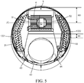
- FIG. 4 and FIG. 5 are separately sectional views, which are along a direction parallel with and perpendicular to an axis of a flow air apparatus, of the embodiment
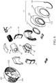
- FIG. 6 is an exploded structural diagram of the embodiment.
- the wall-mounted air conditioner in the embodiment includes an indoor unit, and the indoor unit includes a front housing 11 and a rear housing 12, and the two may be detachably connected, so as to form a housing of the indoor unit.
- orthographic projections of the front housing 11 and the rear housing 12 are both circular or approximately circular, that is, a profile curve of the front housing and a profile curve of the rear housing (which are not shown in the figure) are both circular or approximately circular. Therefore, an orthographic projection of an entire indoor unit is also circular or approximately circular, so that an entire indoor unit has a unique and nice appearance, which is totally different from that of an existing stripe-shaped wall-mounted air conditioner indoor unit and meets a personalized aesthetic demand of a user.
- a structure of the front housing 11 is: for a surface of the front housing 11, both an upper portion 111 of the front housing and a lower portion 112 of the front housing contract backwards, and a middle portion 113 of the front housing protrudes forwards, so that the surface of the front housing 11 is an arc surface in which the upper portion and the lower portion contract inwards and the middle portion protrudes outwards.
- the rear housing 12 is located within a limiting area of the front housing 11. That is, an outer profile curve of the front housing 11 is located outside an outer profile curve of the rear housing 12.
- an area presented by the wall-mounted air conditioner indoor unit is an area of the front housing 11, and because the upper portion and the lower portion of the front housing contract backwards, from the back of frontage, an outline size of the front housing 11 is small.
- the middle portion protrudes outwards, so that in a case in which the outline size is relatively small, a heat exchanger having a relatively large area and a centrifugal fan having a large air intake volume can be disposed inside the housing, to make the indoor unit meet an air volume requirement and a temperature adjustment requirement during air cooling and heating.
- the lower portion of the front housing 11, specifically, the lower portion 112 of the front housing is provided with a mixed air outlet 114.
- the mixed air outlet 114 is disposed on the lower portion 112, whose surface contracts backwards, of the front housing, the mixed air outlet 114 is formed in an inclined direction in which the upper portion is forward, and the lower portion is backward, and an inclined angle of the mixed air outlet 114 is ⁇ meeting 4° ⁇ 45°. More preferably, the inclined angle is about 10°.
- the mixed air outlet 114 is set in this manner, in cooperation with structure design of a subsequent flow air apparatus 3, so that air exhausted from the mixed air outlet 114 can be blown forwards and backwards, which effectively avoids a problem that when the indoor unit is mounted at a relatively high position in a room and air exhausted from an air outlet is blown up to a ceiling, an air volume and temperature adjustment of indoor flow air are affected.
- the front housing 11 includes a front panel 115, a decoration plate 116 and a decoration cover.
- the front panel 115 and the decoration plate 116 have a same outer profile and constitute a body of the front housing 11.
- the decoration plate 116 is located on a front surface of the front panel 115 and is connected to the front panel 115.
- the decoration plate 116 is detachably connected to the front panel 115 by using a buckle and/or a screw; or is stuck to the front panel 115 by using glue. Same openings are formed on the front panel 115 and the decoration plate 116, and the two openings form the mixed air outlet 114.
- the decoration cover includes a detachably connected base 117 and a cover plate 118.
- the two components are buckledly mounted at an edge of the mixed air outlet 114 after being connected, thereby forming a decoration side of the mixed air outlet 114.
- Light in different colors may be set in the decoration cover to brighten the air outlet and give an instruction on exhaustion of air.
- the rear housing 12 as a main part of the housing, has a thickness greater than a thickness of the front housing 11.
- a body of the rear housing 12 is of a cylinder-shaped structure and includes a rear plate 121 and a side wall 122.
- a relatively large accommodation space is formed by means of surrounding, so as to accommodate and place another component of the indoor unit, for example, the heat exchanger, a centrifugal fan, a water pan, and a volute.
- Left and right sides of the side wall 122 are symmetrically provided with a first main air intake portion 1221 and a second main air intake portion 1222.
- the two air intake portions preferably include multiple air inlets that are not connected to each other.
- the air intake portion Compared with an existing air intake grill, the air intake portion has a large air intake volume and easily clean dusts and sundries.
- the front panel 115 in the front housing 11 is connected to the side wall 122.From the front of the indoor unit, both the first main air intake portion 1221 and the second main air intake portion 1222 are located within a limiting area of the front panel 115. Therefore, the mixed air outlet 114 disposed on the lower portion of the front housing 11 is relatively far away from the two main air intake portions, so that a problem that air of the air outlet and the air intake portion is mixed does not occur.
- the rear plate 121 is provided with a mounting surface 1211, the mounting surface 1211 is provided with a wallboard 1212, and the indoor unit is fastened to and mounted on a wall by using the wallboard 1212.
- the rear plate 121 is further provided with a breach 1213, the breach 1213 includes a first surface 1214 perpendicular to and connected to the mounting surface 1211 and a second surface 1215 far away from the mounting surface 1211 and parallel with the mounting surface 1211, the second surface 1215 is provided with a non-hot exchange air inlet 1217, and a position of the non-hot exchange air inlet 1217 corresponds to that of the mixed air outlet 114 of the front housing 11.
- the first surface 1214 is provided with an air intake cavity 1216, and the non-hot exchange air inlet 1217 is partially located in the air intake cavity 1216.
- the foregoing structure is used. After the indoor unit is mounted on the wall, an air intake empty cavity is preserved for the non-hot exchange air inlet 1217, thereby implementing unhindered air intake of the non-hot exchange air inlet 1217 and improving flow air performance of an air conditioner. In addition, an area of the mounting surface 1211 is not reduced and a mounting strength is not affected due to an excessively preserved empty cavity.
- An interior of the housing formed of the front housing 11 and the rear housing 12 is provided with the heat exchanger, a flow air apparatus 3, a centrifugal fan 4, a volute 5, and a surrounding portion 6.
- the flow air apparatus 3 is disposed below and includes three airduct bodies that are sequentially arranged from the front to the rear, that is, in a direction from the front housing 11 to the rear housing 12, which are separately a front airduct body 31, a middle airduct body 32, and a rear airduct body 33. All of the three airduct bodies that are sequentially arranged from the front to the back are ring-shaped.
- the front airduct body 31 is go-through in the middle and has front and rear openings, which are separately a mixed air outlet and an air inlet (which are not shown in the figure).
- the middle airduct body 32 is go-through in the middle and has front and rear openings, which are separately an air outlet and an air inlet (which are not shown in the figure).
- the rear airduct body 33 is go-through in the middle and has front and rear openings, which are separately an air outlet and a non-hot exchange air inlet (which are not shown in the figure).
- a go-through passage (which is not shown in the figure) that goes through all of three airduct bodies from the front to the back is disposed in the middle.
- the mixed air outlet 114 and the non-hot exchange air inlet 1217 are connected by means of the go-through passage.
- a mixed air outlet of the front airduct body 31 and the mixed air outlet 114 are interconnected, and a non-hot exchange air inlet of the rear airduct body 33 and the non-hot exchange air inlet 1217 are interconnected.
- a first hot exchange air passage 34 is disposed between the front airduct body 31 and the middle airduct body 32, and a second ring-shaped hot exchange air passage 35 is disposed between the middle airduct body 32 and the rear airduct body 33. Moreover, both of the two hot exchange air passages are ring-shaped.
- the centrifugal fan 4 is disposed above the flow air apparatus 3 and is located inside the volute 5.
- the centrifugal fan 4 is preferably a double-suction-type centrifugal fan in which rotors of a motor 41 are externally disposed, and an axis z2 of the centrifugal fan 4 is perpendicular to an axis zl of the flow air apparatus 3. Further, internal space of the housing can be effectively used, and a fan length of the centrifugal fan 4 is increased to improve an air volume of the indoor unit and the heat exchange efficiency and reduce power consumption.
- the volute 5 has the first air intake portion 51 and the second air intake portion 52 that are bilaterally symmetrical.
- Openings of the two air intake portions face outwards and can take in air from left and right sides under the function of the centrifugal fan 4.
- An air exhaust portion 53 of the volute 5 faces the flow air apparatus 3, and specifically, faces the two hot exchange air passages of the flow air apparatus 3.
- the air exhaust portion 53 of the volute 5 is provided with a surrounding portion 6 that extends to the flow air apparatus 3 and that surrounds two hot exchange air passages.
- An air mixed cavity is disposed between the surrounding portion 6 and the two hot exchange air passages.
- the air exhaust portion 53 of the volute 5 faces the hot exchange air passage in an inclined direction in which an upper portion is backward and a lower portion is forward, and the surrounding portion 6 surrounds the hot exchange air passage in an inclined direction in which an upper portion is backward and a lower portion is forward. Therefore, air flown out of the volute 5 enters the air mixed cavity and the hot exchange air passage at convenience in an inclined and downward direction and is exhausted by means of the flow air apparatus 3 in an inclined and downward inertial direction.
- the surrounding portion 6 gradually expands downwards relative to the flow air apparatus 3 from a starting end 61 of the surrounding portion 6 connecting to the air exhaust portion 53 of the volute 5, so that a air mixed cavity 63 and a second mixed cavity 64 whose inner cavities gradually expand are formed on left and right sides of the flow air apparatus 3.
- the first air mixed cavity 63 and the second air mixed cavity 64 are bilaterally symmetrical by using a straight line perpendicular to the axis of the flow air apparatus 3 as a symmetry axis. Therefore, hot exchange air flown out of the air exhaust portion 53 of the volute 5 enters the first air mixed cavity 63 and the second air mixed cavity 64 under limiting and guiding of the surrounding portion 6.
- Carding and filling is performed on air currents in the two symmetrical air mixed cavities, and until the air mixed cavities are full, air on the left and right sides has an equal air volume and an equal air speed. Then, the air uniformly enters two ring-shaped hot exchange air passages in left and right and upward directions of the flow air apparatus 3.
- a distance between the top of the flow air apparatus 3 and the air exhaust portion 53 of the volute 5 is H1
- a distance between the bottom of the flow air apparatus 3 and the bottom 62 of the surrounding portion is H2 (which is not shown in the figure), where H1 is greater than H2
- the flow air apparatus 3 and the bottom 62 of the surrounding portion are close to a lower end of the housing as much as possible, so that a length of the surrounding portion 6 can be stretched, which provides an air mixed cavity that has an enough length to fully mix air together.
- a delivery area that has an enough length can be disposed between the surrounding portion 6 and the air exhaust portion 53 of the volute 5, to implement static pressure recovery.
- the bottom of the flow air apparatus 3 is close to or in contact with the bottom 62 of the surrounding portion as much as possible, so that only little air is blown out of bottoms of hot exchange air passages of the flow air apparatus 3. After being blown out of upper and middle portions of the hot exchange air passages, most air is exhausted along a go-through passage and the mixed air outlet 114 in an inclined and downward direction.
- the first hot exchange air passage 34 and the second hot exchange air passage 35 are set in such a manner: For each hot exchange air passage, a size of an upper portion is greater than a size of a lower portion. For example, a width of the hot exchange air passage gradually contracts from up to down, thereby forming a passage structure that is wide at the upper portion and narrow at the lower portion. Because the hot exchange air passage is wide in the upper portion and narrow in the lower portion, air blown out of the air exhaust portion 53 of the volute 5 is mostly blown out via a wider position of the hot exchange air passage, that is, the middle and upper portions, and further, can further enable the air exhausted from the mixed air outlet 114 to move in an inclined and downward direction.
- the three airduct bodies are set in such a manner:
- the three airduct bodies are sequentially arranged in a column in a spacing-gradually-increased structure in a direction from the non-hot exchange air inlet 1217 to the mixed air outlet 114, so that sizes of the hot exchange air passages sequentially become large from the back to the front. That is, a size of the first hot exchange air passage 34 is greater than a size of the second hot exchange air passage 35.
- a width of the first hot exchange air passage 34 is greater than a size of a corresponding position of a second hot exchange air passage 35.
- a distance H3 between an axle centre M of the centrifugal fan 4 and the top of the housing ought to be not less than 1/4 of an overall height of the housing.
- the heat exchangers include a first heat exchanger 21 located between the first main air intake portion 1221 and the volute 5 and a second heat exchanger 22 located between the second main air intake portion 1222 and the volute 5.
- the first main air intake portion 1221 faces the first heat exchanger
- the second main air intake portion 1222 faces the second heat exchanger 22.
- both the first heat exchanger 21 and the second heat exchanger 22 are two-folded and multi-layer heat exchangers, for example, two-folded and four-layer heat exchangers, and extend downwards from the volute 5 to surround a part of the surrounding portion 6.
- non-hot exchange air is guided from the non-hot exchange air inlet 1217 to join final exhaustion of air, which increases an entire air intake volume of an air conditioner, speeds up flow of inner air, and further improves entire uniformity of indoor air.
- mixed air like this is relatively gentle, and when the mixed air is blown to a body of a user, the user feels more comfortable, which improves an experience effect of suitability of the user.
Landscapes
- Engineering & Computer Science (AREA)
- Chemical & Material Sciences (AREA)
- Combustion & Propulsion (AREA)
- Mechanical Engineering (AREA)
- General Engineering & Computer Science (AREA)
- Physics & Mathematics (AREA)
- Thermal Sciences (AREA)
- Air-Conditioning Room Units, And Self-Contained Units In General (AREA)
- Air Filters, Heat-Exchange Apparatuses, And Housings Of Air-Conditioning Units (AREA)
- Duct Arrangements (AREA)
Description
- The present invention relates to the technical field of air adjustment technologies, and specifically, to an air conditioner, and more specifically, to a wall-mounted air conditioner.
- All indoor units of traditional wall-mounted air conditioners are stripe-shaped. The indoor units are provided with stripe-shaped air outlets. A cross-flow fan is disposed inside the indoor unit, and air on which a heat exchanger performs heat exchanging is directly blown out of an air outlet under the function of the interior cross-flow fan.
- With the improvement of living standards and the constant advancement of technologies, people are no longer satisfied with the traditional and personalized requirements increasingly increase. Therefore, in the field of air conditioner technologies, a vertical air conditioner constantly develops, and a vertical air conditioner having stripe-shaped air outlets, a vertical air conditioner exhausting mixed air, and the like appear. However, because of being limited by an installment position, an air flow capability, and costs, a wall-mounted air conditioner does not break the tradition, which limits the development of a wall-mounted air conditioner.
-
KR 2004 0016742 A - An objective of the present invention is to provide a wall-mounted air conditioner, so as to break a traditional structure of an existing wall-mounted air conditioner and exhaust air backwards, thereby ensuring fast flow and temperature adjustment of indoor air.
- To implement the foregoing objective of the present invention, the following technical solutions are used by the present invention for implementation:
A wall-mounted air conditioner includes an indoor unit, where the indoor unit includes a front housing and a rear housing forming housing, the housing is provided with main air intake portions, heat exchangers are disposed inside the housing, orthographic projection of the front housing and the rear housing are both circular or approximately circular, a surface of the front housing is an arc surface in which an upper portion and a lower portion contract backwards and a middle portion protrudes forwards, and a lower portion of the front housing is provided with an air outlet, wherein the rear housing is located within a limiting area of the front housing with an outer profile curve of the front housing being located outside an outer profile curve of the rear housing. - According to the wall-mounted air conditioner as described above, the air outlet is disposed at the lower portion of the front housing in an inclined direction in which an upper portion is forward, and a lower portion is backward, and an inclined angle of the air outlet is 4°-45°.
- According to the wall-mounted air conditioner as described above, the front housing includes a front panel and a decoration plate that is located at a front surface of the front panel and is connected to the front panel.
- According to the wall-mounted air conditioner as described above, the front housing further includes a decoration cover disposed at an edge of the air outlet.
- According to the wall-mounted air conditioner as described above, the rear housing includes a rear plate and a side wall, the front housing is connected to the side wall, and the main air intake portion is disposed on the side wall.
- Preferably, the main air intake portion includes multiple air inlets that are not connected to each other.
- According to the wall-mounted air conditioner as described above, a position that is on the rear housing and that is corresponding to the air outlet is provided with a non-hot exchange air inlet, a flow air apparatus is disposed inside the housing, the flow air apparatus includes at least two airduct bodies that are go-through in the middle and that have front and rear openings, the airduct bodies are sequentially arranged in a column, and a go-through passage that is go-through from the front to the back is disposed in the middle, the go-through passage connects the air outlet and the non-hot exchange air inlet, a hot exchange air passage is disposed between two adjacent airduct bodies of the airduct bodies, a volute and a centrifugal fan located inside the volute are disposed inside the housing and above the flow air apparatus, an air exhaust portion of the volute faces the hot exchange air passage, the air exhaust portion of the volute is further provided with a surrounding portion that extends to the flow air apparatus and that surrounds the hot exchange air passages, and an air mixed cavity is disposed between the surrounding portion and the hot exchange air passages.
- According to the wall-mounted air conditioner as described above, a front opening of a front airduct body, close to the air outlet, of the flow air apparatus inclines downwards in a direction same with the air outlet.
- According to the wall-mounted air conditioner as described above, the rear plate is provided with a breach, the breach includes a first surface connected to a mounting surface of the rear plate and a second surface far away from the mounting surface, and the non-hot exchange air inlet is disposed on the second surface.
- According to the wall-mounted air conditioner as described above, the first surface is further provided with an air intake cavity, and a part of the non-hot exchange air inlet is located within the air intake cavity.
- According to the wall-mounted air conditioner as described above, the mounting surface is provided with a wallboard.
- Compared with the prior art, advantages and positive effects of the present invention are as follows:
According to the present invention, orthographic projections of a front housing and a rear housing of an indoor unit of a wall-mounted air conditioner are both set to be circular or approximately circular, the front housing is set to have an arc surface in which an upper portion and a lower portion contract inwards and a middle portion protrudes forwards, and a lower portion of the front housing is provided with an air outlet, which implements a structure that has a unique and nice appearance and that is totally different from an existing stripe-shaped wall-mounted air conditioner. In addition, according to the air conditioner in the present invention, it can be ensured that at the premise that an entire structure is as small as possible, there is enough inner space to accommodate inner components, so that an air direction is downward, which meets wall-mounted use of a wall-mounted air conditioner and ensures air adjustment performance of an air conditioner. - After specific implementation manners of the present invention are read with reference to the accompanying drawings, another feature and advantage of the present invention is clearer.
-
-
FIG. 1 is a first solid figure of an embodiment of a wall-mounted air conditioner according to the present invention; -
FIG. 2 is a second solid figure of an embodiment of a wall-mounted air conditioner according to the present invention; -
FIG. 3 is a side view of an embodiment of a wall-mounted air conditioner according to the present invention;; -
FIG. 4 is a sectional view along a direction parallel with an axis of a flow air apparatus of an embodiment of a wall-mounted air conditioner according to the present invention; -
FIG. 5 is a sectional view along a direction perpendicular to an axis of a flow air apparatus of an embodiment of a wall-mounted air conditioner according to the present invention; and -
FIG. 6 is an exploded structural diagram of an embodiment of a wall-mounted air conditioner according to the present invention. - To make the objectives, technical solutions, and advantages of the present invention clearer and more comprehensible, the following further describes the present invention in detail with reference to the accompanying drawings and embodiments.
- A brief introduction is first made to technical terms involved in specific implementation manners: "front", "rear", "left", and "right", which are referred to in the following, of each structure are defined relative to a position of a user in a state in which a structure member is normally used. Descriptions: "front", "rear", "left", and "right" on an arrangement position of multiple structure members are also defined relative to a position of a user in a state in which an apparatus formed of multiple structure members is normally used. Hot exchange air described below refers to air that is from an interior of an air conditioner and on which heat exchanging is performed by using a heat exchanger. Non-hot exchange air refers to air that is from environmental space in which an air conditioner is located and that is not directly from a heat exchanger relative to hot exchange air. Mixed air refers to air formed because of mixture of hot exchange air and non-hot exchange air.
- Refer to an embodiment, which is shown in
FIG. 1 to FIG. 6 , of a wall-mounted air conditioner according to the present invention, and specifically, an embodiment of a wall-mounted air conditioner indoor unit. -
FIG. 1 and FIG. 2 are two solid figures of the embodiment,FIG. 3 is a side view of the embodiment,FIG. 4 andFIG. 5 are separately sectional views, which are along a direction parallel with and perpendicular to an axis of a flow air apparatus, of the embodiment, andFIG. 6 is an exploded structural diagram of the embodiment. - The wall-mounted air conditioner in the embodiment includes an indoor unit, and the indoor unit includes a
front housing 11 and arear housing 12, and the two may be detachably connected, so as to form a housing of the indoor unit. Preferably, orthographic projections of thefront housing 11 and therear housing 12 are both circular or approximately circular, that is, a profile curve of the front housing and a profile curve of the rear housing (which are not shown in the figure) are both circular or approximately circular. Therefore, an orthographic projection of an entire indoor unit is also circular or approximately circular, so that an entire indoor unit has a unique and nice appearance, which is totally different from that of an existing stripe-shaped wall-mounted air conditioner indoor unit and meets a personalized aesthetic demand of a user. - Specifically, a structure of the
front housing 11 is: for a surface of thefront housing 11, both anupper portion 111 of the front housing and alower portion 112 of the front housing contract backwards, and amiddle portion 113 of the front housing protrudes forwards, so that the surface of thefront housing 11 is an arc surface in which the upper portion and the lower portion contract inwards and the middle portion protrudes outwards. Therear housing 12 is located within a limiting area of thefront housing 11. That is, an outer profile curve of thefront housing 11 is located outside an outer profile curve of therear housing 12. Therefore, an area presented by the wall-mounted air conditioner indoor unit is an area of thefront housing 11, and because the upper portion and the lower portion of the front housing contract backwards, from the back of frontage, an outline size of thefront housing 11 is small. In addition, the middle portion protrudes outwards, so that in a case in which the outline size is relatively small, a heat exchanger having a relatively large area and a centrifugal fan having a large air intake volume can be disposed inside the housing, to make the indoor unit meet an air volume requirement and a temperature adjustment requirement during air cooling and heating. The lower portion of thefront housing 11, specifically, thelower portion 112 of the front housing, is provided with amixed air outlet 114. The mixedair outlet 114 is disposed on thelower portion 112, whose surface contracts backwards, of the front housing, themixed air outlet 114 is formed in an inclined direction in which the upper portion is forward, and the lower portion is backward, and an inclined angle of the mixedair outlet 114 is α meeting 4°≤α≤45°. More preferably, the inclined angle is about 10°. The mixedair outlet 114 is set in this manner, in cooperation with structure design of a subsequentflow air apparatus 3, so that air exhausted from themixed air outlet 114 can be blown forwards and backwards, which effectively avoids a problem that when the indoor unit is mounted at a relatively high position in a room and air exhausted from an air outlet is blown up to a ceiling, an air volume and temperature adjustment of indoor flow air are affected. - Further, the
front housing 11 includes afront panel 115, adecoration plate 116 and a decoration cover. Thefront panel 115 and thedecoration plate 116 have a same outer profile and constitute a body of thefront housing 11. Thedecoration plate 116 is located on a front surface of thefront panel 115 and is connected to thefront panel 115. For example, thedecoration plate 116 is detachably connected to thefront panel 115 by using a buckle and/or a screw; or is stuck to thefront panel 115 by using glue. Same openings are formed on thefront panel 115 and thedecoration plate 116, and the two openings form themixed air outlet 114. The decoration cover includes a detachably connectedbase 117 and acover plate 118. The two components are buckledly mounted at an edge of themixed air outlet 114 after being connected, thereby forming a decoration side of themixed air outlet 114. Light in different colors may be set in the decoration cover to brighten the air outlet and give an instruction on exhaustion of air. - The
rear housing 12, as a main part of the housing, has a thickness greater than a thickness of thefront housing 11. Besides, a body of therear housing 12 is of a cylinder-shaped structure and includes arear plate 121 and aside wall 122. In the middle of the two parts, a relatively large accommodation space is formed by means of surrounding, so as to accommodate and place another component of the indoor unit, for example, the heat exchanger, a centrifugal fan, a water pan, and a volute. Left and right sides of theside wall 122 are symmetrically provided with a first mainair intake portion 1221 and a second mainair intake portion 1222. The two air intake portions preferably include multiple air inlets that are not connected to each other. Compared with an existing air intake grill, the air intake portion has a large air intake volume and easily clean dusts and sundries. When an integrity is formed, thefront panel 115 in thefront housing 11 is connected to the side wall 122.From the front of the indoor unit, both the first mainair intake portion 1221 and the second mainair intake portion 1222 are located within a limiting area of thefront panel 115. Therefore, themixed air outlet 114 disposed on the lower portion of thefront housing 11 is relatively far away from the two main air intake portions, so that a problem that air of the air outlet and the air intake portion is mixed does not occur. - In addition, the
rear plate 121 is provided with a mountingsurface 1211, the mountingsurface 1211 is provided with awallboard 1212, and the indoor unit is fastened to and mounted on a wall by using thewallboard 1212. Therear plate 121 is further provided with a breach 1213, the breach 1213 includes afirst surface 1214 perpendicular to and connected to the mountingsurface 1211 and asecond surface 1215 far away from the mountingsurface 1211 and parallel with the mountingsurface 1211, thesecond surface 1215 is provided with a non-hotexchange air inlet 1217, and a position of the non-hotexchange air inlet 1217 corresponds to that of themixed air outlet 114 of thefront housing 11. More preferably, thefirst surface 1214 is provided with anair intake cavity 1216, and the non-hotexchange air inlet 1217 is partially located in theair intake cavity 1216. The foregoing structure is used. After the indoor unit is mounted on the wall, an air intake empty cavity is preserved for the non-hotexchange air inlet 1217, thereby implementing unhindered air intake of the non-hotexchange air inlet 1217 and improving flow air performance of an air conditioner. In addition, an area of the mountingsurface 1211 is not reduced and a mounting strength is not affected due to an excessively preserved empty cavity. - An interior of the housing formed of the
front housing 11 and therear housing 12 is provided with the heat exchanger, aflow air apparatus 3, acentrifugal fan 4, avolute 5, and a surrounding portion 6. - Specifically, the
flow air apparatus 3 is disposed below and includes three airduct bodies that are sequentially arranged from the front to the rear, that is, in a direction from thefront housing 11 to therear housing 12, which are separately afront airduct body 31, amiddle airduct body 32, and arear airduct body 33. All of the three airduct bodies that are sequentially arranged from the front to the back are ring-shaped. Thefront airduct body 31 is go-through in the middle and has front and rear openings, which are separately a mixed air outlet and an air inlet (which are not shown in the figure). Themiddle airduct body 32 is go-through in the middle and has front and rear openings, which are separately an air outlet and an air inlet (which are not shown in the figure). Therear airduct body 33 is go-through in the middle and has front and rear openings, which are separately an air outlet and a non-hot exchange air inlet (which are not shown in the figure). After thefront airduct body 31, themiddle airduct body 32, and therear airduct body 33 are sequentially arranged from the front to the back, a go-through passage (which is not shown in the figure) that goes through all of three airduct bodies from the front to the back is disposed in the middle. In addition, themixed air outlet 114 and the non-hotexchange air inlet 1217 are connected by means of the go-through passage. A mixed air outlet of thefront airduct body 31 and themixed air outlet 114 are interconnected, and a non-hot exchange air inlet of therear airduct body 33 and the non-hotexchange air inlet 1217 are interconnected. A first hotexchange air passage 34 is disposed between thefront airduct body 31 and themiddle airduct body 32, and a second ring-shaped hotexchange air passage 35 is disposed between themiddle airduct body 32 and therear airduct body 33. Moreover, both of the two hot exchange air passages are ring-shaped. - The
centrifugal fan 4 is disposed above theflow air apparatus 3 and is located inside thevolute 5. Thecentrifugal fan 4 is preferably a double-suction-type centrifugal fan in which rotors of amotor 41 are externally disposed, and an axis z2 of thecentrifugal fan 4 is perpendicular to an axis zl of theflow air apparatus 3. Further, internal space of the housing can be effectively used, and a fan length of thecentrifugal fan 4 is increased to improve an air volume of the indoor unit and the heat exchange efficiency and reduce power consumption. Correspondingly, thevolute 5 has the firstair intake portion 51 and the secondair intake portion 52 that are bilaterally symmetrical. Openings of the two air intake portions face outwards and can take in air from left and right sides under the function of thecentrifugal fan 4. Anair exhaust portion 53 of thevolute 5 faces theflow air apparatus 3, and specifically, faces the two hot exchange air passages of theflow air apparatus 3. Theair exhaust portion 53 of thevolute 5 is provided with a surrounding portion 6 that extends to theflow air apparatus 3 and that surrounds two hot exchange air passages. An air mixed cavity is disposed between the surrounding portion 6 and the two hot exchange air passages. Specifically, theair exhaust portion 53 of thevolute 5 faces the hot exchange air passage in an inclined direction in which an upper portion is backward and a lower portion is forward, and the surrounding portion 6 surrounds the hot exchange air passage in an inclined direction in which an upper portion is backward and a lower portion is forward. Therefore, air flown out of thevolute 5 enters the air mixed cavity and the hot exchange air passage at convenience in an inclined and downward direction and is exhausted by means of theflow air apparatus 3 in an inclined and downward inertial direction. Moreover, the surrounding portion 6 gradually expands downwards relative to theflow air apparatus 3 from a startingend 61 of the surrounding portion 6 connecting to theair exhaust portion 53 of thevolute 5, so that a airmixed cavity 63 and a secondmixed cavity 64 whose inner cavities gradually expand are formed on left and right sides of theflow air apparatus 3. Moreover, the first airmixed cavity 63 and the second airmixed cavity 64 are bilaterally symmetrical by using a straight line perpendicular to the axis of theflow air apparatus 3 as a symmetry axis. Therefore, hot exchange air flown out of theair exhaust portion 53 of thevolute 5 enters the first airmixed cavity 63 and the second airmixed cavity 64 under limiting and guiding of the surrounding portion 6. Carding and filling is performed on air currents in the two symmetrical air mixed cavities, and until the air mixed cavities are full, air on the left and right sides has an equal air volume and an equal air speed. Then, the air uniformly enters two ring-shaped hot exchange air passages in left and right and upward directions of theflow air apparatus 3. - Moreover, in this embodiment, a distance between the top of the
flow air apparatus 3 and theair exhaust portion 53 of thevolute 5 is H1, and a distance between the bottom of theflow air apparatus 3 and the bottom 62 of the surrounding portion is H2 (which is not shown in the figure), where H1 is greater than H2, and theflow air apparatus 3 and the bottom 62 of the surrounding portion are close to a lower end of the housing as much as possible, so that a length of the surrounding portion 6 can be stretched, which provides an air mixed cavity that has an enough length to fully mix air together. In addition, a delivery area that has an enough length can be disposed between the surrounding portion 6 and theair exhaust portion 53 of thevolute 5, to implement static pressure recovery. In addition, to enable air that is blown out of themixed air outlet 114 to move in an inclined and downward direction, besides that themixed air outlet 114 and the mixed air outlet of thefront airduct body 31 interconnected with themixed air outlet 114 are set to incline downwards in a direction in which an upper portion is forward and a lower portion is backward, the bottom of theflow air apparatus 3 is close to or in contact with the bottom 62 of the surrounding portion as much as possible, so that only little air is blown out of bottoms of hot exchange air passages of theflow air apparatus 3. After being blown out of upper and middle portions of the hot exchange air passages, most air is exhausted along a go-through passage and themixed air outlet 114 in an inclined and downward direction. - More preferably, the first hot
exchange air passage 34 and the second hotexchange air passage 35 are set in such a manner: For each hot exchange air passage, a size of an upper portion is greater than a size of a lower portion. For example, a width of the hot exchange air passage gradually contracts from up to down, thereby forming a passage structure that is wide at the upper portion and narrow at the lower portion. Because the hot exchange air passage is wide in the upper portion and narrow in the lower portion, air blown out of theair exhaust portion 53 of thevolute 5 is mostly blown out via a wider position of the hot exchange air passage, that is, the middle and upper portions, and further, can further enable the air exhausted from themixed air outlet 114 to move in an inclined and downward direction. - Further, the three airduct bodies are set in such a manner: The three airduct bodies are sequentially arranged in a column in a spacing-gradually-increased structure in a direction from the non-hot
exchange air inlet 1217 to themixed air outlet 114, so that sizes of the hot exchange air passages sequentially become large from the back to the front. That is, a size of the first hotexchange air passage 34 is greater than a size of the second hotexchange air passage 35. For example, a width of the first hotexchange air passage 34 is greater than a size of a corresponding position of a second hotexchange air passage 35. Setting like this can ensure that air that is exhausted from a rear end of theair exhaust portion 53 of thevolute 5 and that has a relatively large air speed is fully guided to the go-through passage, increase an air speed in the go-through passage, and further increase an air volume of lured air from thenon-hot exchange air 1217. - For the
centrifugal fan 4, to ensure that efficiency of air intake from left and right sides and exchanging heat by means of an evaporimeter and whole machine vibration reach the standard, a distance H3 between an axle centre M of thecentrifugal fan 4 and the top of the housing ought to be not less than 1/4 of an overall height of the housing. - In this embodiment, corresponding to the first main
air intake portion 1221, the second mainair intake portion 1222, and thecentrifugal fan 4, the heat exchangers include afirst heat exchanger 21 located between the first mainair intake portion 1221 and thevolute 5 and asecond heat exchanger 22 located between the second mainair intake portion 1222 and thevolute 5. The first mainair intake portion 1221 faces thefirst heat exchanger 21, and the second mainair intake portion 1222 faces thesecond heat exchanger 22. Moreover, both thefirst heat exchanger 21 and thesecond heat exchanger 22 are two-folded and multi-layer heat exchangers, for example, two-folded and four-layer heat exchangers, and extend downwards from thevolute 5 to surround a part of the surrounding portion 6. By means of design of this structure, it may be ensured that air of the external is taken into to a low-voltage region of a middle portion of thecentrifugal fan 4 by using the main air intake portions and heat exchangers on two sides in a least-changed angle and shortest distance, thereby reducing a flow channel pressure loss, improving an indoor circulation air volume, and reducing noises of a whole machine. Moreover, air on which flow adjustment and static pressure recovery are performed by thecentrifugal fan 4 is collected in the air mixed cavity and is blown out by theflow air apparatus 3 out of themixed air outlet 114. When the air is blown out, by using a pressure in the go-through passage in theflow air apparatus 3, non-hot exchange air is guided from the non-hotexchange air inlet 1217 to join final exhaustion of air, which increases an entire air intake volume of an air conditioner, speeds up flow of inner air, and further improves entire uniformity of indoor air. Moreover, mixed air like this is relatively gentle, and when the mixed air is blown to a body of a user, the user feels more comfortable, which improves an experience effect of suitability of the user. - The foregoing embodiments are merely intended for describing the technical solutions of the present invention but not for limiting the present invention. Although the present invention is described in detail with reference to the foregoing embodiments, persons of ordinary skill in the art may still make modifications to the technical solutions recorded in the foregoing embodiments or make equivalent replacements to some technical features thereof. These modifications or replacements do not make the essence of the corresponding technical solutions depart from the scope of the technical solutions of the present invention as defined by the appending claims.
Claims (11)
- A wall-mounted air conditioner, comprising an indoor unit, wherein the indoor unit comprises a front housing (11) and a rear housing (12) forming housing, the housing is provided with main air intake portions (1221, 1222), heat exchangers (21, 22) are disposed inside the housing, orthographic projection of the front housing and the rear housing are both circular or approximately circular, a surface of the front housing is an arc surface in which an upper portion (111) and a lower portion (112) contract backwards and a middle portion (113) protrudes forwards, and a lower portion of the front housing is provided with an air outlet (114),
characterized in that,
the rear housing (12) is located within a limiting area of the front housing (12) with an outer profile curve of the front housing (11) being located outside an outer profile curve of the rear housing (12). - The wall-mounted air conditioner according to claim 1, wherein the air outlet (114) is disposed at the lower portion (112) of the front housing (11) in an inclined direction in which an upper portion is forward, and a lower portion is backward, and an inclined angle (α) of the air outlet is 4°-45°.
- The wall-mounted air conditioner according to claim 1, wherein the front housing (11) comprises a front panel (115) and a decoration plate (116) that is located at a front surface of the front panel (115) and is connected to the front panel (115).
- The wall-mounted air conditioner according to claim 3, wherein the front housing (11) further comprises a decoration cover disposed at an edge of the air outlet.
- The wall-mounted air conditioner according to any one of claims 1 to 4, wherein the rear housing (12) comprises a rear plate (121) and a side wall (122), the front housing (11) is connected to the side wall (122), and the main air intake portion (1221, 1222) is disposed on the side wall (122).
- The wall-mounted air conditioner according to claim 5, wherein the main air intake portion (1221, 1222) comprises multiple air inlets that are not connected to each other.
- The wall-mounted air conditioner according to claim 5, wherein a position that is on the rear housing (12) and that is corresponding to the air outlet (114) is provided with a non-hot exchange air inlet (1217), a flow air apparatus (3) is disposed inside the housing, the flow air apparatus (3) comprises at least two airduct bodies (31, 32, 33) that are go-through in the middle and that have front and rear openings, the airduct bodies (31, 32, 33) are sequentially arranged in a column, and a go-through passage that is go-through from the front to the back is disposed in the middle, the go-through passage connects the air outlet (114) and the non-hot exchange air inlet (1217), a hot exchange air passage (34, 35) is disposed between two adjacent airduct bodies (31, 32 / 32, 33) of the airduct bodies (31, 32, 33), a volute (5) and a centrifugal fan (4) located inside the volute (5) are disposed inside the housing and above the flow air apparatus (3), an air exhaust portion (53) of the volute faces the hot exchange air passage (34, 35), the air exhaust portion (53) of the volute (5) is further provided with a surrounding portion (6) that extends to the flow air apparatus (3) and that surrounds the hot exchange air passages (34, 35), and an air mixed cavity (63, 64) is disposed between the surrounding portion (6) and the hot exchange air passages (34, 35).
- The wall-mounted air conditioner according to claim 7, wherein a front opening of a front airduct body (31), close to the air outlet (114), of the flow air apparatus (3) inclines downwards in a direction same with the air outlet (114).
- The wall-mounted air conditioner according to claim 7, wherein the rear plate (121) is provided with a breach (1213), the breach (1213) comprises a first surface (1214) connected to a mounting surface (1211) of the rear plate (121) and a second surface (1215) far away from the mounting surface (1211), and the non-hot exchange air inlet (1217) is disposed on the second surface (1215).
- The wall-mounted air conditioner according to claim 9, wherein the first surface (1214) is further provided with an air intake cavity (1216), and a part of the non-hot exchange air inlet (1217) is located within the air intake cavity (1216).
- The wall-mounted air conditioner according to claim 9, wherein the mounting surface (1211) is provided with a wallboard (1212).
Applications Claiming Priority (2)
| Application Number | Priority Date | Filing Date | Title |
|---|---|---|---|
| CN201410434353.2A CN104807079B (en) | 2014-08-29 | 2014-08-29 | A kind of wall-hanging air conditioner |
| PCT/CN2015/074190 WO2016029677A1 (en) | 2014-08-29 | 2015-03-13 | Wall-mounted air conditioner |
Publications (3)
| Publication Number | Publication Date |
|---|---|
| EP3051214A1 EP3051214A1 (en) | 2016-08-03 |
| EP3051214A4 EP3051214A4 (en) | 2016-10-19 |
| EP3051214B1 true EP3051214B1 (en) | 2018-08-22 |
Family
ID=53692146
Family Applications (1)
| Application Number | Title | Priority Date | Filing Date |
|---|---|---|---|
| EP15835236.9A Active EP3051214B1 (en) | 2014-08-29 | 2015-03-13 | Wall-mounted air conditioner |
Country Status (6)
| Country | Link |
|---|---|
| US (1) | US10295201B2 (en) |
| EP (1) | EP3051214B1 (en) |
| JP (1) | JP6396503B2 (en) |
| KR (1) | KR101904188B1 (en) |
| CN (1) | CN104807079B (en) |
| WO (1) | WO2016029677A1 (en) |
Families Citing this family (14)
| Publication number | Priority date | Publication date | Assignee | Title |
|---|---|---|---|---|
| CN104807080B (en) * | 2014-08-29 | 2017-08-01 | 青岛海尔空调器有限总公司 | A kind of wall-hanging indoor unit of air conditioner |
| WO2016029678A1 (en) * | 2014-08-29 | 2016-03-03 | 青岛海尔空调器有限总公司 | Wall-mounted air conditioner indoor unit |
| CN105423417B (en) * | 2015-11-06 | 2019-07-23 | 青岛海尔空调器有限总公司 | Air conditioner indoor unit |
| CN105485783B (en) * | 2016-01-28 | 2018-07-03 | 海信(广东)空调有限公司 | Air conditioner indoor unit |
| CN105673569B (en) * | 2016-03-28 | 2019-06-28 | 广东美的制冷设备有限公司 | Fan assembly, air conditioner indoor unit and air conditioner |
| CN106440065A (en) * | 2016-11-29 | 2017-02-22 | 海信(山东)空调有限公司 | Wall-hanging air-conditioner indoor unit and air-conditioner |
| CN106839122A (en) * | 2017-03-17 | 2017-06-13 | 广东美的制冷设备有限公司 | Indoor apparatus of air conditioner and the air-conditioner with it |
| CN110762607B (en) * | 2018-07-26 | 2021-04-20 | 青岛海尔空调器有限总公司 | Air conditioner hanging machine |
| CN111503733A (en) * | 2019-01-31 | 2020-08-07 | 青岛海尔空调器有限总公司 | Cabinet air conditioner indoor unit |
| RU193240U1 (en) * | 2019-03-04 | 2019-10-21 | Дмитрий Викторович Алексеев | Screen protector for ceiling diffuser |
| CN114263635A (en) * | 2020-09-16 | 2022-04-01 | 珠海格力电器股份有限公司 | Volute component, wall-mounted unit and air conditioner |
| CN214415871U (en) * | 2020-12-09 | 2021-10-19 | 深圳市安拓浦科技有限公司 | Wall-mounted air purifier |
| US12611909B2 (en) | 2021-03-18 | 2026-04-28 | Gentherm Incorporated | Preconditioning surfaces using intelligent thermal effectors |
| WO2022198216A1 (en) * | 2021-03-18 | 2022-09-22 | Gentherm Incorporated | Optimal control of convective thermal devices |
Family Cites Families (59)
| Publication number | Priority date | Publication date | Assignee | Title |
|---|---|---|---|---|
| GB1533801A (en) * | 1976-08-16 | 1978-11-29 | Royair Ltd | Adjustable diffuser for ventilating systems |
| DE2653161C2 (en) * | 1976-11-23 | 1981-09-24 | Schako Verwaltung Beck KG, 7790 Meßkirch | Air distribution box for ventilation and air conditioning systems |
| JPS56149537A (en) * | 1980-04-18 | 1981-11-19 | Toshiba Corp | Indoor unit of separation type air conditioner |
| JPS56149536A (en) * | 1980-04-18 | 1981-11-19 | Toshiba Corp | Indoor unit of separation type air conditioner |
| US4763565A (en) * | 1987-04-17 | 1988-08-16 | American Metal Products Company | Convertible air diffuser |
| JPH0625790Y2 (en) * | 1988-08-16 | 1994-07-06 | 暖冷工業株式会社 | Air conditioner outlet structure |
| US5001968A (en) * | 1989-06-02 | 1991-03-26 | Hudson Associates, Inc. | Grocery store air conditioning system having drop-down diffuser units therefor |
| JPH04198655A (en) * | 1990-11-28 | 1992-07-20 | Sanbetsuku Kk | Dew formation prohibiting blowing port in air conditioner |
| US5333835A (en) * | 1993-07-22 | 1994-08-02 | American Standard Inc. | Electric motor driven air valve |
| US5658196A (en) * | 1995-11-09 | 1997-08-19 | Marjorie L. Trigg | Insulated air diffuser |
| KR100231907B1 (en) * | 1996-09-04 | 1999-12-01 | 김윤규 | An opening and closing device for the damper of an air diffuser indicating amount of opening and closing |
| US5954580A (en) * | 1997-11-21 | 1999-09-21 | Thermolec Ltee. | Air diffuser and damper assembly |
| US6119463A (en) * | 1998-05-12 | 2000-09-19 | Amerigon | Thermoelectric heat exchanger |
| US6458028B2 (en) * | 1999-12-17 | 2002-10-01 | Darryl L. Snyder | Diffuser and ceiling fan combination |
| EP1321721B1 (en) * | 2000-09-29 | 2008-08-06 | Mitsubishi Denki Kabushiki Kaisha | Air conditioner |
| US6336338B1 (en) * | 2000-11-13 | 2002-01-08 | Uri Koren | Room air conditioner |
| BRPI0207869B1 (en) * | 2001-03-02 | 2016-04-12 | Ramesh Nana Mhatre | central air conditioning system diffuser and the method of manufacturing the central air conditioning system diffuser |
| JP3651417B2 (en) * | 2001-07-18 | 2005-05-25 | ダイキン工業株式会社 | Air conditioner |
| US6797028B2 (en) * | 2002-02-13 | 2004-09-28 | 3M Innovative Properties Company | “Push-on” self attach adaptive filter |
| ITVI20020154A1 (en) * | 2002-07-10 | 2004-01-12 | Xiang Srl | MONOBLOCK AIR CONDITIONER |
| KR100474051B1 (en) * | 2002-08-19 | 2005-03-08 | 삼성전자주식회사 | Air conditioner |
| US7662036B2 (en) * | 2002-10-07 | 2010-02-16 | Ramesh Nana Mhatre | 3-cone diffuser |
| CN1203281C (en) * | 2002-11-02 | 2005-05-25 | 海尔集团公司 | Indoor unit of wall hanging type air conditioner |
| US6779348B2 (en) * | 2002-11-04 | 2004-08-24 | Tandis, Inc. | Thermoelectrically controlled blower |
| JP2004270984A (en) * | 2003-03-06 | 2004-09-30 | Fujitsu General Ltd | Air conditioner |
| KR20040104772A (en) * | 2003-06-03 | 2004-12-13 | 삼성전자주식회사 | Turbofan and air conditioner with the same |
| US7249466B2 (en) | 2003-09-04 | 2007-07-31 | Lg Electronics Inc. | Indoor unit in air conditioner |
| US20050164626A1 (en) * | 2004-01-26 | 2005-07-28 | Kloostra Marvin L. | High mix air diffuser |
| WO2005085716A1 (en) * | 2004-03-04 | 2005-09-15 | Lg Electronics Inc. | Indoor unit in air conditioner |
| US20060054712A1 (en) * | 2004-09-13 | 2006-03-16 | Guolian Wu | Vertical dehumidifier |
| CN2909086Y (en) * | 2005-04-25 | 2007-06-06 | 海尔集团公司 | Indoor unit evaporimeter of hanging air conditioner |
| US8206475B2 (en) * | 2006-06-23 | 2012-06-26 | Veft Aerospace Technology Inc. | Entrainment air flow control and filtration devices |
| US20080064318A1 (en) * | 2006-09-07 | 2008-03-13 | Brushstrokes Design Studio, Inc. | Ventilation fan and hanging light fixture arrangement |
| US20090170421A1 (en) * | 2008-01-02 | 2009-07-02 | Adrian John R | Grille |
| US9249982B2 (en) * | 2008-04-03 | 2016-02-02 | Airvisor Inc. | Ceiling vent diffuser |
| US8002013B2 (en) * | 2008-04-03 | 2011-08-23 | Airvisor Inc. | Ceiling vent diffuser |
| US8701422B2 (en) * | 2008-06-03 | 2014-04-22 | Bsst Llc | Thermoelectric heat pump |
| JP4676520B2 (en) * | 2008-08-28 | 2011-04-27 | シャープ株式会社 | Integrated air conditioner |
| EP2463599B1 (en) * | 2009-08-05 | 2019-05-08 | Mitsubishi Electric Corporation | Wall-hanging air conditioner |
| US20110262114A1 (en) * | 2010-03-25 | 2011-10-27 | Josephine Montgomery | 3 way rechargeable heating and cooling units |
| US8734106B2 (en) * | 2010-05-28 | 2014-05-27 | AH-HA Designs, Inc. | Ceiling fixture protection system and method |
| CN102338422A (en) * | 2010-07-20 | 2012-02-01 | 乐金电子(天津)电器有限公司 | Indoor unit of hanging-type air conditioner and hanging-type air conditioner adopting same |
| CN102374584B (en) * | 2010-08-20 | 2015-08-05 | 乐金电子(天津)电器有限公司 | Improve the indoor set of airflow circulating and adopt the hanging air conditioner of this indoor set |
| KR101240536B1 (en) | 2011-12-08 | 2013-03-11 | 엘지전자 주식회사 | An air conditioner |
| JP5997539B2 (en) * | 2012-08-08 | 2016-09-28 | 株式会社日立製作所 | Air supply system |
| GB2510195B (en) * | 2013-01-29 | 2016-04-27 | Dyson Technology Ltd | A fan assembly |
| CN203116173U (en) * | 2013-03-13 | 2013-08-07 | 泰铂(上海)实业有限公司 | Round wall-mounted air-conditioner indoor unit |
| US9857092B2 (en) * | 2013-03-15 | 2018-01-02 | American Louver Company | Injection molded HVAC diffuser assembly |
| CN103604203B (en) * | 2013-04-17 | 2015-06-10 | 海尔集团公司 | Air supply method for vertical air conditioner |
| EP3006837B1 (en) * | 2013-05-31 | 2019-09-18 | Midea Group Co., Ltd. | Air supply apparatus used for air conditioner and air conditioner indoor unit having the same |
| KR102199376B1 (en) * | 2013-07-12 | 2021-01-06 | 엘지전자 주식회사 | Centrifugal blower and air conditioner using the same |
| US9696060B2 (en) * | 2014-01-12 | 2017-07-04 | Paul E. Hohmann | Temperature sensing air diffuser |
| EP2921794B1 (en) * | 2014-03-18 | 2020-06-10 | Samsung Electronics Co., Ltd. | Air conditioner |
| TWI557377B (en) * | 2014-06-04 | 2016-11-11 | Qing-Ke Zhang | Portable DC air conditioner |
| WO2016029678A1 (en) * | 2014-08-29 | 2016-03-03 | 青岛海尔空调器有限总公司 | Wall-mounted air conditioner indoor unit |
| CN104807080B (en) * | 2014-08-29 | 2017-08-01 | 青岛海尔空调器有限总公司 | A kind of wall-hanging indoor unit of air conditioner |
| CN204084607U (en) * | 2014-08-29 | 2015-01-07 | 青岛海尔空调器有限总公司 | Wall-hanging indoor unit of air conditioner |
| CN204240479U (en) * | 2014-11-03 | 2015-04-01 | 青岛海尔空调器有限总公司 | A kind of wall-hanging indoor unit of air conditioner |
| CN204240478U (en) * | 2014-11-03 | 2015-04-01 | 青岛海尔空调器有限总公司 | Wall-hanging indoor unit of air conditioner |
-
2014
- 2014-08-29 CN CN201410434353.2A patent/CN104807079B/en active Active
-
2015
- 2015-03-13 WO PCT/CN2015/074190 patent/WO2016029677A1/en not_active Ceased
- 2015-03-13 US US15/109,535 patent/US10295201B2/en active Active
- 2015-03-13 EP EP15835236.9A patent/EP3051214B1/en active Active
- 2015-03-13 KR KR1020167034616A patent/KR101904188B1/en active Active
- 2015-03-13 JP JP2016570241A patent/JP6396503B2/en active Active
Non-Patent Citations (1)
| Title |
|---|
| None * |
Also Published As
| Publication number | Publication date |
|---|---|
| CN104807079B (en) | 2018-04-27 |
| JP2017525919A (en) | 2017-09-07 |
| EP3051214A4 (en) | 2016-10-19 |
| KR20170008777A (en) | 2017-01-24 |
| US20160327285A1 (en) | 2016-11-10 |
| CN104807079A (en) | 2015-07-29 |
| KR101904188B1 (en) | 2018-11-13 |
| JP6396503B2 (en) | 2018-09-26 |
| US10295201B2 (en) | 2019-05-21 |
| WO2016029677A1 (en) | 2016-03-03 |
| EP3051214A1 (en) | 2016-08-03 |
Similar Documents
| Publication | Publication Date | Title |
|---|---|---|
| EP3051221B1 (en) | Wall-mounted air conditioner indoor unit | |
| US10295201B2 (en) | Wall-mounted air conditioner | |
| EP3051215B1 (en) | Wall-mounted air conditioner indoor unit | |
| CN104807078B (en) | Wall-mounted air conditioner indoor unit | |
| CN204240478U (en) | Wall-hanging indoor unit of air conditioner | |
| CN204084607U (en) | Wall-hanging indoor unit of air conditioner | |
| CN105091084B (en) | A kind of indoor apparatus of air conditioner | |
| CN105485762B (en) | A kind of Split wall-mounted type air conditioner | |
| CN107062572B (en) | Hanging type air conditioner indoor unit | |
| CN205156154U (en) | air conditioner | |
| CN105485761B (en) | Split wall-mounted type air conditioner | |
| CN205191745U (en) | air conditioner | |
| CN209042565U (en) | Air conditioner indoor unit | |
| CN209054660U (en) | Air conditioner indoor unit | |
| CN205448027U (en) | Wall -mounted air conditioner indoor unit and air conditioner | |
| CN203928140U (en) | A kind of indoor apparatus of air conditioner | |
| CN110864369A (en) | Air conditioner indoor unit | |
| CN108286742B (en) | air conditioner indoor unit | |
| CN205279271U (en) | Wall -mounted air conditioner |
Legal Events
| Date | Code | Title | Description |
|---|---|---|---|
| PUAI | Public reference made under article 153(3) epc to a published international application that has entered the european phase |
Free format text: ORIGINAL CODE: 0009012 |
|
| 17P | Request for examination filed |
Effective date: 20160428 |
|
| AK | Designated contracting states |
Kind code of ref document: A1 Designated state(s): AL AT BE BG CH CY CZ DE DK EE ES FI FR GB GR HR HU IE IS IT LI LT LU LV MC MK MT NL NO PL PT RO RS SE SI SK SM TR |
|
| AX | Request for extension of the european patent |
Extension state: BA ME |
|
| A4 | Supplementary search report drawn up and despatched |
Effective date: 20160919 |
|
| RIC1 | Information provided on ipc code assigned before grant |
Ipc: F24F 13/20 20060101ALI20160913BHEP Ipc: F24F 1/00 20110101AFI20160913BHEP |
|
| STAA | Information on the status of an ep patent application or granted ep patent |
Free format text: STATUS: EXAMINATION IS IN PROGRESS |
|
| DAV | Request for validation of the european patent (deleted) | ||
| DAX | Request for extension of the european patent (deleted) | ||
| 17Q | First examination report despatched |
Effective date: 20171110 |
|
| GRAP | Despatch of communication of intention to grant a patent |
Free format text: ORIGINAL CODE: EPIDOSNIGR1 |
|
| STAA | Information on the status of an ep patent application or granted ep patent |
Free format text: STATUS: GRANT OF PATENT IS INTENDED |
|
| INTG | Intention to grant announced |
Effective date: 20180504 |
|
| GRAS | Grant fee paid |
Free format text: ORIGINAL CODE: EPIDOSNIGR3 |
|
| GRAA | (expected) grant |
Free format text: ORIGINAL CODE: 0009210 |
|
| STAA | Information on the status of an ep patent application or granted ep patent |
Free format text: STATUS: THE PATENT HAS BEEN GRANTED |
|
| AK | Designated contracting states |
Kind code of ref document: B1 Designated state(s): AL AT BE BG CH CY CZ DE DK EE ES FI FR GB GR HR HU IE IS IT LI LT LU LV MC MK MT NL NO PL PT RO RS SE SI SK SM TR |
|
| REG | Reference to a national code |
Ref country code: GB Ref legal event code: FG4D |
|
| REG | Reference to a national code |
Ref country code: CH Ref legal event code: EP |
|
| REG | Reference to a national code |
Ref country code: AT Ref legal event code: REF Ref document number: 1032965 Country of ref document: AT Kind code of ref document: T Effective date: 20180915 |
|
| REG | Reference to a national code |
Ref country code: IE Ref legal event code: FG4D |
|
| REG | Reference to a national code |
Ref country code: DE Ref legal event code: R096 Ref document number: 602015015277 Country of ref document: DE |
|
| REG | Reference to a national code |
Ref country code: NL Ref legal event code: MP Effective date: 20180822 |
|
| REG | Reference to a national code |
Ref country code: LT Ref legal event code: MG4D |
|
| PG25 | Lapsed in a contracting state [announced via postgrant information from national office to epo] |
Ref country code: FI Free format text: LAPSE BECAUSE OF FAILURE TO SUBMIT A TRANSLATION OF THE DESCRIPTION OR TO PAY THE FEE WITHIN THE PRESCRIBED TIME-LIMIT Effective date: 20180822 Ref country code: RS Free format text: LAPSE BECAUSE OF FAILURE TO SUBMIT A TRANSLATION OF THE DESCRIPTION OR TO PAY THE FEE WITHIN THE PRESCRIBED TIME-LIMIT Effective date: 20180822 Ref country code: GR Free format text: LAPSE BECAUSE OF FAILURE TO SUBMIT A TRANSLATION OF THE DESCRIPTION OR TO PAY THE FEE WITHIN THE PRESCRIBED TIME-LIMIT Effective date: 20181123 Ref country code: IS Free format text: LAPSE BECAUSE OF FAILURE TO SUBMIT A TRANSLATION OF THE DESCRIPTION OR TO PAY THE FEE WITHIN THE PRESCRIBED TIME-LIMIT Effective date: 20181222 Ref country code: NO Free format text: LAPSE BECAUSE OF FAILURE TO SUBMIT A TRANSLATION OF THE DESCRIPTION OR TO PAY THE FEE WITHIN THE PRESCRIBED TIME-LIMIT Effective date: 20181122 Ref country code: SE Free format text: LAPSE BECAUSE OF FAILURE TO SUBMIT A TRANSLATION OF THE DESCRIPTION OR TO PAY THE FEE WITHIN THE PRESCRIBED TIME-LIMIT Effective date: 20180822 Ref country code: NL Free format text: LAPSE BECAUSE OF FAILURE TO SUBMIT A TRANSLATION OF THE DESCRIPTION OR TO PAY THE FEE WITHIN THE PRESCRIBED TIME-LIMIT Effective date: 20180822 Ref country code: BG Free format text: LAPSE BECAUSE OF FAILURE TO SUBMIT A TRANSLATION OF THE DESCRIPTION OR TO PAY THE FEE WITHIN THE PRESCRIBED TIME-LIMIT Effective date: 20181122 Ref country code: LT Free format text: LAPSE BECAUSE OF FAILURE TO SUBMIT A TRANSLATION OF THE DESCRIPTION OR TO PAY THE FEE WITHIN THE PRESCRIBED TIME-LIMIT Effective date: 20180822 |
|
| REG | Reference to a national code |
Ref country code: AT Ref legal event code: MK05 Ref document number: 1032965 Country of ref document: AT Kind code of ref document: T Effective date: 20180822 |
|
| PG25 | Lapsed in a contracting state [announced via postgrant information from national office to epo] |
Ref country code: AL Free format text: LAPSE BECAUSE OF FAILURE TO SUBMIT A TRANSLATION OF THE DESCRIPTION OR TO PAY THE FEE WITHIN THE PRESCRIBED TIME-LIMIT Effective date: 20180822 Ref country code: LV Free format text: LAPSE BECAUSE OF FAILURE TO SUBMIT A TRANSLATION OF THE DESCRIPTION OR TO PAY THE FEE WITHIN THE PRESCRIBED TIME-LIMIT Effective date: 20180822 Ref country code: HR Free format text: LAPSE BECAUSE OF FAILURE TO SUBMIT A TRANSLATION OF THE DESCRIPTION OR TO PAY THE FEE WITHIN THE PRESCRIBED TIME-LIMIT Effective date: 20180822 |
|
| PG25 | Lapsed in a contracting state [announced via postgrant information from national office to epo] |
Ref country code: ES Free format text: LAPSE BECAUSE OF FAILURE TO SUBMIT A TRANSLATION OF THE DESCRIPTION OR TO PAY THE FEE WITHIN THE PRESCRIBED TIME-LIMIT Effective date: 20180822 Ref country code: PL Free format text: LAPSE BECAUSE OF FAILURE TO SUBMIT A TRANSLATION OF THE DESCRIPTION OR TO PAY THE FEE WITHIN THE PRESCRIBED TIME-LIMIT Effective date: 20180822 Ref country code: RO Free format text: LAPSE BECAUSE OF FAILURE TO SUBMIT A TRANSLATION OF THE DESCRIPTION OR TO PAY THE FEE WITHIN THE PRESCRIBED TIME-LIMIT Effective date: 20180822 Ref country code: CZ Free format text: LAPSE BECAUSE OF FAILURE TO SUBMIT A TRANSLATION OF THE DESCRIPTION OR TO PAY THE FEE WITHIN THE PRESCRIBED TIME-LIMIT Effective date: 20180822 Ref country code: AT Free format text: LAPSE BECAUSE OF FAILURE TO SUBMIT A TRANSLATION OF THE DESCRIPTION OR TO PAY THE FEE WITHIN THE PRESCRIBED TIME-LIMIT Effective date: 20180822 Ref country code: EE Free format text: LAPSE BECAUSE OF FAILURE TO SUBMIT A TRANSLATION OF THE DESCRIPTION OR TO PAY THE FEE WITHIN THE PRESCRIBED TIME-LIMIT Effective date: 20180822 |
|
| REG | Reference to a national code |
Ref country code: DE Ref legal event code: R097 Ref document number: 602015015277 Country of ref document: DE |
|
| PG25 | Lapsed in a contracting state [announced via postgrant information from national office to epo] |
Ref country code: DK Free format text: LAPSE BECAUSE OF FAILURE TO SUBMIT A TRANSLATION OF THE DESCRIPTION OR TO PAY THE FEE WITHIN THE PRESCRIBED TIME-LIMIT Effective date: 20180822 Ref country code: SM Free format text: LAPSE BECAUSE OF FAILURE TO SUBMIT A TRANSLATION OF THE DESCRIPTION OR TO PAY THE FEE WITHIN THE PRESCRIBED TIME-LIMIT Effective date: 20180822 Ref country code: SK Free format text: LAPSE BECAUSE OF FAILURE TO SUBMIT A TRANSLATION OF THE DESCRIPTION OR TO PAY THE FEE WITHIN THE PRESCRIBED TIME-LIMIT Effective date: 20180822 |
|
| PLBE | No opposition filed within time limit |
Free format text: ORIGINAL CODE: 0009261 |
|
| STAA | Information on the status of an ep patent application or granted ep patent |
Free format text: STATUS: NO OPPOSITION FILED WITHIN TIME LIMIT |
|
| 26N | No opposition filed |
Effective date: 20190523 |
|
| PG25 | Lapsed in a contracting state [announced via postgrant information from national office to epo] |
Ref country code: SI Free format text: LAPSE BECAUSE OF FAILURE TO SUBMIT A TRANSLATION OF THE DESCRIPTION OR TO PAY THE FEE WITHIN THE PRESCRIBED TIME-LIMIT Effective date: 20180822 |
|
| PG25 | Lapsed in a contracting state [announced via postgrant information from national office to epo] |
Ref country code: MC Free format text: LAPSE BECAUSE OF FAILURE TO SUBMIT A TRANSLATION OF THE DESCRIPTION OR TO PAY THE FEE WITHIN THE PRESCRIBED TIME-LIMIT Effective date: 20180822 |
|
| REG | Reference to a national code |
Ref country code: CH Ref legal event code: PL |
|
| PG25 | Lapsed in a contracting state [announced via postgrant information from national office to epo] |
Ref country code: LU Free format text: LAPSE BECAUSE OF NON-PAYMENT OF DUE FEES Effective date: 20190313 |
|
| REG | Reference to a national code |
Ref country code: BE Ref legal event code: MM Effective date: 20190331 |
|
| PG25 | Lapsed in a contracting state [announced via postgrant information from national office to epo] |
Ref country code: CH Free format text: LAPSE BECAUSE OF NON-PAYMENT OF DUE FEES Effective date: 20190331 Ref country code: LI Free format text: LAPSE BECAUSE OF NON-PAYMENT OF DUE FEES Effective date: 20190331 Ref country code: IE Free format text: LAPSE BECAUSE OF NON-PAYMENT OF DUE FEES Effective date: 20190313 |
|
| PG25 | Lapsed in a contracting state [announced via postgrant information from national office to epo] |
Ref country code: BE Free format text: LAPSE BECAUSE OF NON-PAYMENT OF DUE FEES Effective date: 20190331 |
|
| PG25 | Lapsed in a contracting state [announced via postgrant information from national office to epo] |
Ref country code: TR Free format text: LAPSE BECAUSE OF FAILURE TO SUBMIT A TRANSLATION OF THE DESCRIPTION OR TO PAY THE FEE WITHIN THE PRESCRIBED TIME-LIMIT Effective date: 20180822 |
|
| PG25 | Lapsed in a contracting state [announced via postgrant information from national office to epo] |
Ref country code: MT Free format text: LAPSE BECAUSE OF NON-PAYMENT OF DUE FEES Effective date: 20190313 Ref country code: PT Free format text: LAPSE BECAUSE OF FAILURE TO SUBMIT A TRANSLATION OF THE DESCRIPTION OR TO PAY THE FEE WITHIN THE PRESCRIBED TIME-LIMIT Effective date: 20181222 |
|
| PG25 | Lapsed in a contracting state [announced via postgrant information from national office to epo] |
Ref country code: CY Free format text: LAPSE BECAUSE OF FAILURE TO SUBMIT A TRANSLATION OF THE DESCRIPTION OR TO PAY THE FEE WITHIN THE PRESCRIBED TIME-LIMIT Effective date: 20180822 |
|
| PG25 | Lapsed in a contracting state [announced via postgrant information from national office to epo] |
Ref country code: HU Free format text: LAPSE BECAUSE OF FAILURE TO SUBMIT A TRANSLATION OF THE DESCRIPTION OR TO PAY THE FEE WITHIN THE PRESCRIBED TIME-LIMIT; INVALID AB INITIO Effective date: 20150313 |
|
| PG25 | Lapsed in a contracting state [announced via postgrant information from national office to epo] |
Ref country code: MK Free format text: LAPSE BECAUSE OF FAILURE TO SUBMIT A TRANSLATION OF THE DESCRIPTION OR TO PAY THE FEE WITHIN THE PRESCRIBED TIME-LIMIT Effective date: 20180822 |
|
| PGFP | Annual fee paid to national office [announced via postgrant information from national office to epo] |
Ref country code: GB Payment date: 20260323 Year of fee payment: 12 |
|
| PGFP | Annual fee paid to national office [announced via postgrant information from national office to epo] |
Ref country code: DE Payment date: 20260313 Year of fee payment: 12 |
|
| PGFP | Annual fee paid to national office [announced via postgrant information from national office to epo] |
Ref country code: IT Payment date: 20260310 Year of fee payment: 12 |
|
| PGFP | Annual fee paid to national office [announced via postgrant information from national office to epo] |
Ref country code: FR Payment date: 20260330 Year of fee payment: 12 |