EP3051211A1 - A cooking device comprising a cover having an illuminating member - Google Patents
A cooking device comprising a cover having an illuminating member Download PDFInfo
- Publication number
- EP3051211A1 EP3051211A1 EP16150371.9A EP16150371A EP3051211A1 EP 3051211 A1 EP3051211 A1 EP 3051211A1 EP 16150371 A EP16150371 A EP 16150371A EP 3051211 A1 EP3051211 A1 EP 3051211A1
- Authority
- EP
- European Patent Office
- Prior art keywords
- cover
- illuminating member
- top plate
- illuminating
- cooking device
- Prior art date
- Legal status (The legal status is an assumption and is not a legal conclusion. Google has not performed a legal analysis and makes no representation as to the accuracy of the status listed.)
- Granted
Links
Images



Classifications
-
- F—MECHANICAL ENGINEERING; LIGHTING; HEATING; WEAPONS; BLASTING
- F24—HEATING; RANGES; VENTILATING
- F24C—DOMESTIC STOVES OR RANGES ; DETAILS OF DOMESTIC STOVES OR RANGES, OF GENERAL APPLICATION
- F24C15/00—Details
-
- F—MECHANICAL ENGINEERING; LIGHTING; HEATING; WEAPONS; BLASTING
- F21—LIGHTING
- F21V—FUNCTIONAL FEATURES OR DETAILS OF LIGHTING DEVICES OR SYSTEMS THEREOF; STRUCTURAL COMBINATIONS OF LIGHTING DEVICES WITH OTHER ARTICLES, NOT OTHERWISE PROVIDED FOR
- F21V33/00—Structural combinations of lighting devices with other articles, not otherwise provided for
- F21V33/0004—Personal or domestic articles
- F21V33/0044—Household appliances, e.g. washing machines or vacuum cleaners
Definitions
- the invention relates to a cooking device having an upper profile comprising an illuminating member and fixed on a cover which is hinged to a body of the cooking device.
- Household cooking devices are usually manufactured in a structure as only a hob or a range with a hob having a top plate part integrated to an oven part.
- the hobs have a cover covering the top plate while the hob is not in use or retaining open while the hob is in use.
- the cover is manufactured from ceramic or particularly glass materials.
- illuminating of a top plate of the cooking device and therefore cooking pans on the top plate is provided by an illuminating member which is disposed on the cover particularly on the upper profile of the cooking device.
- a cooking hob includes a cover pivotable between a horizontal position, covering a top surface of the hob and an upright position in which the top surface is exposed.
- a fluorescent light is mounted on the cover adjacent a front edge thereof and can illuminate the top surface whenever the cover is in the upright position.
- the invention relates to a domestic appliance comprising at least one cooking surface and a cover for protecting this cooking surface. It is characterized in that it comprises, associated with the cover, means, for illuminating the surface of the hot plate of the cooking surface, so as to illuminate the top of the dishes placed on the hot plate.
- Object of the invention is to illuminate the top plate and therefore cooking pans on the top plate in an efficient manner particularly in efficient angles.
- the invention relates to a cooking device having a body, a cover hinged to the body and an illuminating member having a light source on the cover. Position of the illuminating member on the cover in an opened position of the cover is arranged with a ⁇ angle according to a horizontal direction of the top plate (x) and the ⁇ angle is in an angle range between (0-46)°.
- the illuminating member is arranged and disposed on the cover as illuminating to the surface area of the top plate directly and all of the surface area of the top plate.
- the ⁇ angle is chosen from the position angle range (0-46)° where the light beams coming from the illuminating member covers almost full surface area of the top plate. Thus almost full surface area of the top plate is illuminated in an efficient manner.
- an optimum position angle for the illuminating member is provided at a 23° angle according to a horizontal direction of the top plate (x).
- the optimum desired illumination for the top plate is provided.
- the illuminating member is provided on an upper edge which edge in an upper position of the cover.
- the illuminating member is disposed on the cover in a proper place which sees the top plate.
- the illuminating member is fixed to an upper profile of the cover.
- the illuminating member is fixed in a secure place and a proper position for eyes of the user.
- the illuminating member is disposed in a housing of the upper profile.
- the illuminating member is fixed in a securable manner to the upper profile.
- the illuminating member can be disposed in the housing of the upper profile as embedded and this provides an esthetical view for the upper profile.
- the invention relates to a cooking device (1) comprising a cover (19) with an illuminating member (5).
- the illuminating member (5) is disposed on the cover (19) especially on an upper profile (23) of the cover (19) in an angled manner.
- the cooking device (1) can be structured as a hob (13) (figure-6) or a cooking device (1) with the hob (13) integrated on a body (11) which has at least one cooking chamber (12) (figure-7).
- the hob (13) is set on a top plate (14).
- the top plate (14) is integrated to the body (11).
- There is a pan-support (16) which will support cooking pans and burners (15) on the top plate (14).
- a control panel (17) is disposed on a front side of the body (11) where easy to reach. Buttons (18) adjusting properly a heat of the cooking chamber (12) and/or a gas flow for the burners (15), are disposed on the control panel (17).
- the body (11) has a door (25) for providing to reach the cooking chamber (12) and closing an opening in front of the cooking chamber (12).
- a hinge (4) provides to pivot the cover (19) of the cooking device (1) on the body (11) of the cooking device (1) ( figure 6 and figure 7 ).
- Two hinges (4) are used for hinging and pivoting one cover (19).
- the cover (19) is pivoted to the body (11) of the cooking device (1), detachably.
- An upper profile (23) is formed in a manner being adaptable to an upper side of the cover (19) of the hob (13) ( figure 3 , 6 , 7 ).
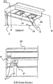
- Detail-A is a detail view taken from the figure 6 .
- the upper profile (23) has at least one housing (24) for disposing at least one illuminating member (5) to the upper profile (23).
- Two illuminating members (5) are disposed in two housings (24) at the embodiment in figure 6 , detail-A.
- B-B Cross section is a cross-section taken from the detail-A.
- the upper profile (23) is manufactured from a metal material.
- the cover (19) is manufactured from a ceramic-based material particularly a glass material.
- the hinge (4) is manufactured from a non-conductive material particularly a glass-fiber reinforced plastic. In an alternative embodiment, the hinge (4) can be manufactured from a conductive material. In this case, security measures are taken by applying electrical insulation on the hinge (4).
- electrical transmission means (3) and terminals (31) are transmitting electrical energy to the illuminating members (5) ( figure 6 , 7 ). Electrical transmission means (3) are mounted onto both sides of the cover (19) of the top plate (14).
- the electrical transmission means (3) on the cover (19) is preferably a conductive strip. Each conductive strip is solely loaded with positively or negatively charged at both two ends.
- the conductive strip can be coated with a nonconductive material.
- the electrical transmission member (3) on the cover (19) can be a cable (5).
- the electrical transmission means (3) charged negatively or positively for transmitting the electrical energy to the illuminating member (5).
- the illuminating member (5) operates at low voltages.
- the illuminating member (5) can be a LED illumination element, a fluorescent lamp.
- an alternating current (AC) will be transmitting on lines of the electrical transmission means (3)
- the electrical transmission means (3) are charged as phase (positive and negative loads) or neutral.
- a direct current (DC) will be transmitting on lines of the electrical transmission means (3)
- the positive and negative charged lines are formed separately. In this way, an occurrence of a short circuit is prevented.
- An electronic card (22) which is disposed on the body (11) converts the current from AC to DC at a desired voltage value.
- the voltage value on the conductive strips is between 0-60 volts.
- the conductive strips are manufactured from a metal material comprising silver ion or/and copper ion having a high electrical conductivity capacity. A wall thickness and a length of the conductive strips are formed and adjusted considering a predetermined voltage value which will be transmitted from one end to the another end of the conductive strip.
- Fixing of the conductive strips onto the cover (19) is provided via coating the conductive strip onto the cover (19).
- the fixing can be done in different methods.
- the conductive strips can adhered onto the cover (19) by an adherent.
- the electric transmission means (3) on the cover (19) are fixed to a terminal (31) on the upper profile (23).
- the electric transmission means (3) in the upper profile (23) disposed in manner that continuing from the terminal (31) towards the illuminating member (5) (B-B cross section).
- the cooking device (1) has a covering member (6).
- the upper profile (23) is in a hollow form. So the upper profile (23) has an opening extending through the inside the upper profile (23). And at both sides of the upper profile (23) has openings. So, the covering members (6) are closing the openings and protecting the electrical transmission means (3) and also some parts of the illuminating members (5) which is inside the upper profile (23).
- the energy supply is chosen as a SELV (safety extra low voltage/ separated extra low voltage) system.
- SELV safety extra low voltage/ separated extra low voltage
- an angle between the cover (19) and the top plate (14) is 90° or approximately 100°.
- a switching member (21) is set on the body (11) for switching on/off to the illuminating members (5).
- a contact with an energy supply is controlled by means of the switching member (21).
- the switching member (21) can be a button with touch or mechanical operated.
- the illuminating members (5) can be operated with voice command.
- the electrical energy for the illuminating members (5) can be supplied by a battery or batteries.
- the switching member (21) can be disposed on the upper profile (23) or on the illuminating member (5) or on the cover (19).
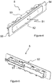
- FIG 4 is a perspective view from the front of the illuminating member (5).
- the illuminating member (5) is a LED illumination.
- Figure 5 is a perspective view from the back side of the illuminating member (5).
- the illuminating member (5) comprises a housing (53) for disposing a light source (51) inside the housing (53) in a securable manner, a flange (54) at an upper face of the housing (53) as forming a frame, a diffuser (52) on the housing (53) and on the light source (51) for diffusing the light beams which are coming from the light source (51).
- the housing (53) of the illuminating member (5) is disposed in the housing (24) of the upper profile (23).
- Water or liquid tightness is provided by disposing a sealing member under a periphery (55) of the illuminating member (5) and in the housing (24) or between the periphery (55) of the illuminating member (5) and the housing (24) (not given in the figures).
- Figure 3 is a two dimensional view of an upper profile (23) with the illuminating member (5), taken from figure 6 .
- the illuminating member (5) is disposed on the cover (19) especially on an upper profile (23) of the cover (19) in an angled manner.
- the upper profile (23) is mounted to an upper edge which edge of the cover (19) in an opened position of the cover (19).
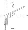
- Figure 1 is a two dimensional view of the upper profile (23) from one side.
- the position of the illuminating member (5) and therefore the upper profile (23) is provided by a ⁇ angle according to a horizontal direction of the top plate (x).
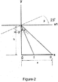
- Figure 2 is a representative view shoving angles related to the upper profile (23) and illuminating member (5) according to the cover (19).
- the object of the invention is to provide a cooking device (1) having at least one illuminating member (5) illuminating the top plate (14) and therefore cooking pans on the top plate (14) in an efficient manner particularly in efficient angles.
- the optimum angle range provides to illuminate all surface area of the top plate (14).
- the position angle of the illuminating member (5) will be arranged at an angle between 0-2 ⁇ angles. So, the position angle of the illuminating member (5) will be in this angle range.
- the optimum position angle of the illuminating member (5) is 23°.
- 0° angle position of the illuminating member (5) is a parallel direction to x direction which is in a horizontal direction of the top plate (14).
- the positions are defined as 0, I and II points on the x direction.
- the surface area of the top plate (14) which the illumination is desired, is between 0-II points on the x direction.
- 0 point is an illuminating focal point of the light source (51) in a parallel position to the top plate (14).
- I point is an illuminating focal point position of the light source (51) to the top plate (14) with a ⁇ angle.
- II point is an illuminating focal point position of the light source (51) to the top plate (14) with a 2 ⁇ angle.
- the "a” and “h” values can be changed as basing to the lengths of the top plate (14) and the cover (19).
- the position angle of the illuminating member (5) is calculated by considering minimum and maximum length of the cooking device (1).
Landscapes
- Engineering & Computer Science (AREA)
- General Engineering & Computer Science (AREA)
- Chemical & Material Sciences (AREA)
- Combustion & Propulsion (AREA)
- Mechanical Engineering (AREA)
- Electric Stoves And Ranges (AREA)
Abstract
Description
- The invention relates to a cooking device having an upper profile comprising an illuminating member and fixed on a cover which is hinged to a body of the cooking device.
- Household cooking devices are usually manufactured in a structure as only a hob or a range with a hob having a top plate part integrated to an oven part. The hobs have a cover covering the top plate while the hob is not in use or retaining open while the hob is in use. The cover is manufactured from ceramic or particularly glass materials.
- In the prior art, illuminating of a top plate of the cooking device and therefore cooking pans on the top plate is provided by an illuminating member which is disposed on the cover particularly on the upper profile of the cooking device.
- One of the embodiment in the related art can be seen from the patent application with the publication number;
GB2143029. A - Another embodiment in the related art can be seen from the patent application with the publication number;
FR2598204 - Object of the invention is to illuminate the top plate and therefore cooking pans on the top plate in an efficient manner particularly in efficient angles.
- In order to achieve above object, the invention relates to a cooking device having a body, a cover hinged to the body and an illuminating member having a light source on the cover. Position of the illuminating member on the cover in an opened position of the cover is arranged with a β angle according to a horizontal direction of the top plate (x) and the β angle is in an angle range between (0-46)°. Thus, the illuminating member is arranged and disposed on the cover as illuminating to the surface area of the top plate directly and all of the surface area of the top plate.
- In a possible embodiment of the invention, the β angle is chosen from the position angle range (0-46)° where the light beams coming from the illuminating member covers almost full surface area of the top plate. Thus almost full surface area of the top plate is illuminated in an efficient manner.
- In another possible embodiment of the invention, an optimum position angle for the illuminating member is provided at a 23° angle according to a horizontal direction of the top plate (x). Thus the optimum desired illumination for the top plate is provided.
- In another possible embodiment of the invention, the illuminating member is provided on an upper edge which edge in an upper position of the cover. Thus the illuminating member is disposed on the cover in a proper place which sees the top plate.
- In another possible embodiment of the invention, the illuminating member is fixed to an upper profile of the cover. Thus, the illuminating member is fixed in a secure place and a proper position for eyes of the user.
- In another possible embodiment of the invention, the illuminating member is disposed in a housing of the upper profile. Thus the illuminating member is fixed in a securable manner to the upper profile. The illuminating member can be disposed in the housing of the upper profile as embedded and this provides an esthetical view for the upper profile.
- Figure 1
- is a two dimensional view of an upper profile from one side.
- Figure 2
- is a representative view shoving angles related to the upper profile and illuminating member according to the cover.
- Figure 3
- is a two dimensional view of an upper profile with the illuminating member, taken from
figure 6 . - Figure 4
- is a perspective view from the front of the illuminating member.
- Figure 5
- is a perspective view from the back side of the illuminating member.
- Figure 6
- is a perspective view from the front of a cooking device as a hob.
- Detail-A
- is a detail view taken from the
figure 6 . - B-B Cross section
- is a cross-section taken from the detail-A.
- Figure 7
- is a perspective view from the front of a cooking device.
- The invention relates to a cooking device (1) comprising a cover (19) with an illuminating member (5). The illuminating member (5) is disposed on the cover (19) especially on an upper profile (23) of the cover (19) in an angled manner.
- The cooking device (1) can be structured as a hob (13) (figure-6) or a cooking device (1) with the hob (13) integrated on a body (11) which has at least one cooking chamber (12) (figure-7). The hob (13) is set on a top plate (14). The top plate (14) is integrated to the body (11). There is a pan-support (16) which will support cooking pans and burners (15) on the top plate (14). A control panel (17) is disposed on a front side of the body (11) where easy to reach. Buttons (18) adjusting properly a heat of the cooking chamber (12) and/or a gas flow for the burners (15), are disposed on the control panel (17). The body (11) has a door (25) for providing to reach the cooking chamber (12) and closing an opening in front of the cooking chamber (12).
- A hinge (4) provides to pivot the cover (19) of the cooking device (1) on the body (11) of the cooking device (1) (
figure 6 andfigure 7 ). Two hinges (4) are used for hinging and pivoting one cover (19). The cover (19) is pivoted to the body (11) of the cooking device (1), detachably. - An upper profile (23) is formed in a manner being adaptable to an upper side of the cover (19) of the hob (13) (
figure 3 ,6 ,7 ). Detail-A is a detail view taken from thefigure 6 . The upper profile (23) has at least one housing (24) for disposing at least one illuminating member (5) to the upper profile (23). Two illuminating members (5) are disposed in two housings (24) at the embodiment infigure 6 , detail-A. B-B Cross section is a cross-section taken from the detail-A. - The upper profile (23) is manufactured from a metal material. The cover (19) is manufactured from a ceramic-based material particularly a glass material. The hinge (4) is manufactured from a non-conductive material particularly a glass-fiber reinforced plastic. In an alternative embodiment, the hinge (4) can be manufactured from a conductive material. In this case, security measures are taken by applying electrical insulation on the hinge (4).
- In one embodiment of the invention, electrical transmission means (3) and terminals (31) are transmitting electrical energy to the illuminating members (5) (
figure 6 ,7 ). Electrical transmission means (3) are mounted onto both sides of the cover (19) of the top plate (14). - The electrical transmission means (3) on the cover (19) is preferably a conductive strip. Each conductive strip is solely loaded with positively or negatively charged at both two ends. The conductive strip can be coated with a nonconductive material. In an alternative embodiment of the invention, the electrical transmission member (3) on the cover (19) can be a cable (5).
- The electrical transmission means (3) charged negatively or positively for transmitting the electrical energy to the illuminating member (5). The illuminating member (5) operates at low voltages. For instance, the illuminating member (5) can be a LED illumination element, a fluorescent lamp.
- If an alternating current (AC) will be transmitting on lines of the electrical transmission means (3), the electrical transmission means (3) are charged as phase (positive and negative loads) or neutral. If a direct current (DC) will be transmitting on lines of the electrical transmission means (3), the positive and negative charged lines are formed separately. In this way, an occurrence of a short circuit is prevented. An electronic card (22) which is disposed on the body (11) converts the current from AC to DC at a desired voltage value. The voltage value on the conductive strips is between 0-60 volts. The conductive strips are manufactured from a metal material comprising silver ion or/and copper ion having a high electrical conductivity capacity. A wall thickness and a length of the conductive strips are formed and adjusted considering a predetermined voltage value which will be transmitted from one end to the another end of the conductive strip.
- Fixing of the conductive strips onto the cover (19) is provided via coating the conductive strip onto the cover (19). In an alternative embodiment of the invention, the fixing can be done in different methods. The conductive strips can adhered onto the cover (19) by an adherent. And the electric transmission means (3) on the cover (19) are fixed to a terminal (31) on the upper profile (23). And also there is electric transmission means (3) in the upper profile (23) disposed in manner that continuing from the terminal (31) towards the illuminating member (5) (B-B cross section). And the cooking device (1) has a covering member (6). The upper profile (23) is in a hollow form. So the upper profile (23) has an opening extending through the inside the upper profile (23). And at both sides of the upper profile (23) has openings. So, the covering members (6) are closing the openings and protecting the electrical transmission means (3) and also some parts of the illuminating members (5) which is inside the upper profile (23).
- In the case of transforming a direct current (DC), the energy supply is chosen as a SELV (safety extra low voltage/ separated extra low voltage) system. Thus, the user can touch reliably to the low voltage charged conductive strips.
- In an opened position of the cover (19) on the top plate (14), an angle between the cover (19) and the top plate (14) is 90° or approximately 100°.
- A switching member (21) is set on the body (11) for switching on/off to the illuminating members (5). A contact with an energy supply is controlled by means of the switching member (21). The switching member (21) can be a button with touch or mechanical operated. In an alternative embodiment, instead of this switching member (21) the illuminating members (5) can be operated with voice command.
- In a preferred embodiment of the present invention, the electrical energy for the illuminating members (5) can be supplied by a battery or batteries. And the switching member (21) can be disposed on the upper profile (23) or on the illuminating member (5) or on the cover (19).
-
Figure 4 is a perspective view from the front of the illuminating member (5). The illuminating member (5) is a LED illumination.Figure 5 is a perspective view from the back side of the illuminating member (5). The illuminating member (5) comprises a housing (53) for disposing a light source (51) inside the housing (53) in a securable manner, a flange (54) at an upper face of the housing (53) as forming a frame, a diffuser (52) on the housing (53) and on the light source (51) for diffusing the light beams which are coming from the light source (51). The housing (53) of the illuminating member (5) is disposed in the housing (24) of the upper profile (23). Water or liquid tightness is provided by disposing a sealing member under a periphery (55) of the illuminating member (5) and in the housing (24) or between the periphery (55) of the illuminating member (5) and the housing (24) (not given in the figures). -
Figure 3 is a two dimensional view of an upper profile (23) with the illuminating member (5), taken fromfigure 6 . The illuminating member (5) is disposed on the cover (19) especially on an upper profile (23) of the cover (19) in an angled manner. The upper profile (23) is mounted to an upper edge which edge of the cover (19) in an opened position of the cover (19).Figure 1 is a two dimensional view of the upper profile (23) from one side. The position of the illuminating member (5) and therefore the upper profile (23) is provided by a β angle according to a horizontal direction of the top plate (x).Figure 2 is a representative view shoving angles related to the upper profile (23) and illuminating member (5) according to the cover (19). - In a detail explanation of the invention, the object of the invention is to provide a cooking device (1) having at least one illuminating member (5) illuminating the top plate (14) and therefore cooking pans on the top plate (14) in an efficient manner particularly in efficient angles. The optimum angle range provides to illuminate all surface area of the top plate (14). According to this purpose, the position angle of the illuminating member (5) will be arranged at an angle between 0-2β angles. So, the position angle of the illuminating member (5) will be in this angle range.
- The calculation formula for the angle is below.
- a is the length of the top plate from one side and,
a = 570
h is the height of the illuminating member on the cover from the top plate and,
h = 550 - a= 570
h= 550
tan (2β)= a / h = 570/550 - 2β = arctan (1,03636)
β≈ 23 - According to this values and this calculation, the optimum position angle of the illuminating member (5) is 23°. 0° angle position of the illuminating member (5) is a parallel direction to x direction which is in a horizontal direction of the top plate (14).
- So the positions are defined as 0, I and II points on the x direction. The surface area of the top plate (14) which the illumination is desired, is between 0-II points on the x direction. 0 point is an illuminating focal point of the light source (51) in a parallel position to the top plate (14).
- I point is an illuminating focal point position of the light source (51) to the top plate (14) with a β angle.
- II point is an illuminating focal point position of the light source (51) to the top plate (14) with a 2β angle.
- In a preferred embodiment of the present invention, the "a" and "h" values can be changed as basing to the lengths of the top plate (14) and the cover (19). However, the position angle of the illuminating member (5) is calculated by considering minimum and maximum length of the cooking device (1).
-
- 1.
- Cooking device
- 11.
- Body
- 12.
- Cooking chamber
- 13.
- Hob
- 14.
- Top plate
- 15.
- Burner
- 16.
- Pan-support
- 17.
- Control panel
- 18.
- Button
- 19.
- Cover
- 21.
- Switching member
- 22.
- Electronic card
- 23.
- Upper profile
- 24.
- Housing
- 25.
- Door
- 3.
- Electric transmission means
- 31.
- Terminal
- 4.
- Hinge
- 5.
- Illuminating member
- 51.
- Light source
- 52.
- Diffuser
- 53.
- Housing
- 54.
- Flange
- 55.
- Periphery
- 6.
- Covering member
- x:
- A horizontal direction of the top plate
- x1:
- A parallel direction to x direction
- y:
- A vertical direction of the cover
- a:
- The length of the top plate
- h:
- The height of the illuminating member on the cover from the top plate
- β:
- Angle of position of the illuminating member
- 0 point:
- An illuminating focal point of the Light source in a parallel position to the top plate
- I point:
- An illuminating focal point position of the Light source to the top plate with a β angle
- II point:
- An illuminating focal point position of the Light source to the top plate with a 2β angle
Claims (6)
- A cooking device (1) having a body (11), a cover (19) hinged to the body (11) and an illuminating member (5) having a light source (51) on the cover (19), characterized in that position of the illuminating member (5) on the cover (19) in an opened position of the cover (19) is arranged with a β angle according to a horizontal direction of the top plate (x) and the β angle is in an angle range between (0-46)°.
- A cooking device (1) according to claim 1, wherein the β angle is chosen from the position angle range (0-46)° where the light beams coming from illuminating member (5) covers almost full surface area of the top plate (14).
- A cooking device (1) according to claim 1, wherein an optimum position angle for the illuminating member (5) is provided at a 23° angle according to a horizontal direction of the top plate (x).
- A cooking device (1) according to any of the preceding claims, wherein the illuminating member (5) is provided on an upper edge which edge in an upper position of the cover (19).
- A cooking device (1) according to claim 1 to 3, wherein the illuminating member (5) is fixed to an upper profile (23) of the cover (19).
- A cooking device (1) according to claim 5, wherein the illuminating member (5) is disposed in a housing (24) of the upper profile (23).
Applications Claiming Priority (1)
| Application Number | Priority Date | Filing Date | Title |
|---|---|---|---|
| TR201501099 | 2015-01-30 |
Publications (2)
| Publication Number | Publication Date |
|---|---|
| EP3051211A1 true EP3051211A1 (en) | 2016-08-03 |
| EP3051211B1 EP3051211B1 (en) | 2021-12-01 |
Family
ID=55070885
Family Applications (1)
| Application Number | Title | Priority Date | Filing Date |
|---|---|---|---|
| EP16150371.9A Active EP3051211B1 (en) | 2015-01-30 | 2016-01-07 | A cooking device comprising a cover having an illuminating member |
Country Status (1)
| Country | Link |
|---|---|
| EP (1) | EP3051211B1 (en) |
Cited By (1)
| Publication number | Priority date | Publication date | Assignee | Title |
|---|---|---|---|---|
| CN110985936A (en) * | 2019-12-17 | 2020-04-10 | 广东德豪润达照明电气有限公司 | Adjustable lamp |
Citations (2)
| Publication number | Priority date | Publication date | Assignee | Title |
|---|---|---|---|---|
| GB2143029A (en) | 1983-07-07 | 1985-01-30 | Emi Plc Thorn | Cooking hob |
| FR2598204A1 (en) | 1986-04-30 | 1987-11-06 | Europ Equip Menager | Domestic appliance comprising at least one cooking surface, and a protective cover for the cooking surface, and a device for illuminating this cooking surface |
Family Cites Families (1)
| Publication number | Priority date | Publication date | Assignee | Title |
|---|---|---|---|---|
| DE102010040509A1 (en) * | 2010-09-09 | 2012-03-15 | BSH Bosch und Siemens Hausgeräte GmbH | Hood |
-
2016
- 2016-01-07 EP EP16150371.9A patent/EP3051211B1/en active Active
Patent Citations (2)
| Publication number | Priority date | Publication date | Assignee | Title |
|---|---|---|---|---|
| GB2143029A (en) | 1983-07-07 | 1985-01-30 | Emi Plc Thorn | Cooking hob |
| FR2598204A1 (en) | 1986-04-30 | 1987-11-06 | Europ Equip Menager | Domestic appliance comprising at least one cooking surface, and a protective cover for the cooking surface, and a device for illuminating this cooking surface |
Cited By (1)
| Publication number | Priority date | Publication date | Assignee | Title |
|---|---|---|---|---|
| CN110985936A (en) * | 2019-12-17 | 2020-04-10 | 广东德豪润达照明电气有限公司 | Adjustable lamp |
Also Published As
| Publication number | Publication date |
|---|---|
| EP3051211B1 (en) | 2021-12-01 |
Similar Documents
| Publication | Publication Date | Title |
|---|---|---|
| US20260031291A1 (en) | Control device base that attaches to the paddle actuator of a mechanical switch | |
| US10741339B2 (en) | Retrofit remote control devices | |
| CA2779115C (en) | Household appliance having a warming drawer with a thermally conductive layer | |
| CA2778706C (en) | Household appliance having supports supporting a glass heating element of a warming drawer | |
| US12073974B2 (en) | Transformer with transparent terminal block | |
| EP3051211B1 (en) | A cooking device comprising a cover having an illuminating member | |
| US20130319994A1 (en) | Household appliance having a drip guard for a warming drawer | |
| WO2014102384A1 (en) | An illuminated knob, a switching mechanism for the illuminated knob and a gas/electric cooking appliance wherein the same are used | |
| US20090296371A1 (en) | Control device for an appliance | |
| EP3037734B1 (en) | Portable cooking assembly with a foldable hood | |
| EP3040625B1 (en) | A cooking device with hinged cover having an illuminating member | |
| EP2833052A1 (en) | Luminaire | |
| US20190086063A1 (en) | Electronic device for installing in a switch cabinet, which electronic device has a first and a second fastener | |
| EP3062024B1 (en) | A household appliance having an electrical connection with a terminal member | |
| EP3012533B1 (en) | A cooking device having a cover with an electrical connection | |
| EP3172491B1 (en) | A cooking device having an electrical transmission element | |
| US20130323662A1 (en) | Household appliance having a thermostat retainer for a thermostat of a warming drawer | |
| EP3086067A1 (en) | Chest freezer | |
| CN209705824U (en) | A kind of lamps and lanterns | |
| US20220065436A1 (en) | Lighting system for fixtures and appliances | |
| EP3034947A1 (en) | A cooking device having a covering element fixed to an upper profile | |
| KR20100064643A (en) | A aooker | |
| CN217039782U (en) | Drawer oven | |
| KR101600954B1 (en) | Module type electric range | |
| CN102575870A (en) | Hot water reservoir having service cover |
Legal Events
| Date | Code | Title | Description |
|---|---|---|---|
| PUAI | Public reference made under article 153(3) epc to a published international application that has entered the european phase |
Free format text: ORIGINAL CODE: 0009012 |
|
| AK | Designated contracting states |
Kind code of ref document: A1 Designated state(s): AL AT BE BG CH CY CZ DE DK EE ES FI FR GB GR HR HU IE IS IT LI LT LU LV MC MK MT NL NO PL PT RO RS SE SI SK SM TR |
|
| AX | Request for extension of the european patent |
Extension state: BA ME |
|
| STAA | Information on the status of an ep patent application or granted ep patent |
Free format text: STATUS: REQUEST FOR EXAMINATION WAS MADE |
|
| 17P | Request for examination filed |
Effective date: 20170203 |
|
| RBV | Designated contracting states (corrected) |
Designated state(s): AL AT BE BG CH CY CZ DE DK EE ES FI FR GB GR HR HU IE IS IT LI LT LU LV MC MK MT NL NO PL PT RO RS SE SI SK SM TR |
|
| STAA | Information on the status of an ep patent application or granted ep patent |
Free format text: STATUS: EXAMINATION IS IN PROGRESS |
|
| 17Q | First examination report despatched |
Effective date: 20170522 |
|
| GRAP | Despatch of communication of intention to grant a patent |
Free format text: ORIGINAL CODE: EPIDOSNIGR1 |
|
| STAA | Information on the status of an ep patent application or granted ep patent |
Free format text: STATUS: GRANT OF PATENT IS INTENDED |
|
| INTG | Intention to grant announced |
Effective date: 20210715 |
|
| GRAS | Grant fee paid |
Free format text: ORIGINAL CODE: EPIDOSNIGR3 |
|
| GRAA | (expected) grant |
Free format text: ORIGINAL CODE: 0009210 |
|
| STAA | Information on the status of an ep patent application or granted ep patent |
Free format text: STATUS: THE PATENT HAS BEEN GRANTED |
|
| AK | Designated contracting states |
Kind code of ref document: B1 Designated state(s): AL AT BE BG CH CY CZ DE DK EE ES FI FR GB GR HR HU IE IS IT LI LT LU LV MC MK MT NL NO PL PT RO RS SE SI SK SM TR |
|
| REG | Reference to a national code |
Ref country code: GB Ref legal event code: FG4D |
|
| REG | Reference to a national code |
Ref country code: AT Ref legal event code: REF Ref document number: 1452111 Country of ref document: AT Kind code of ref document: T Effective date: 20211215 Ref country code: CH Ref legal event code: EP |
|
| REG | Reference to a national code |
Ref country code: IE Ref legal event code: FG4D |
|
| REG | Reference to a national code |
Ref country code: DE Ref legal event code: R096 Ref document number: 602016066723 Country of ref document: DE |
|
| REG | Reference to a national code |
Ref country code: LT Ref legal event code: MG9D |
|
| REG | Reference to a national code |
Ref country code: NL Ref legal event code: MP Effective date: 20211201 |
|
| REG | Reference to a national code |
Ref country code: AT Ref legal event code: MK05 Ref document number: 1452111 Country of ref document: AT Kind code of ref document: T Effective date: 20211201 |
|
| PG25 | Lapsed in a contracting state [announced via postgrant information from national office to epo] |
Ref country code: RS Free format text: LAPSE BECAUSE OF FAILURE TO SUBMIT A TRANSLATION OF THE DESCRIPTION OR TO PAY THE FEE WITHIN THE PRESCRIBED TIME-LIMIT Effective date: 20211201 Ref country code: LT Free format text: LAPSE BECAUSE OF FAILURE TO SUBMIT A TRANSLATION OF THE DESCRIPTION OR TO PAY THE FEE WITHIN THE PRESCRIBED TIME-LIMIT Effective date: 20211201 Ref country code: FI Free format text: LAPSE BECAUSE OF FAILURE TO SUBMIT A TRANSLATION OF THE DESCRIPTION OR TO PAY THE FEE WITHIN THE PRESCRIBED TIME-LIMIT Effective date: 20211201 Ref country code: BG Free format text: LAPSE BECAUSE OF FAILURE TO SUBMIT A TRANSLATION OF THE DESCRIPTION OR TO PAY THE FEE WITHIN THE PRESCRIBED TIME-LIMIT Effective date: 20220301 Ref country code: AT Free format text: LAPSE BECAUSE OF FAILURE TO SUBMIT A TRANSLATION OF THE DESCRIPTION OR TO PAY THE FEE WITHIN THE PRESCRIBED TIME-LIMIT Effective date: 20211201 |
|
| PG25 | Lapsed in a contracting state [announced via postgrant information from national office to epo] |
Ref country code: SE Free format text: LAPSE BECAUSE OF FAILURE TO SUBMIT A TRANSLATION OF THE DESCRIPTION OR TO PAY THE FEE WITHIN THE PRESCRIBED TIME-LIMIT Effective date: 20211201 Ref country code: PL Free format text: LAPSE BECAUSE OF FAILURE TO SUBMIT A TRANSLATION OF THE DESCRIPTION OR TO PAY THE FEE WITHIN THE PRESCRIBED TIME-LIMIT Effective date: 20211201 Ref country code: NO Free format text: LAPSE BECAUSE OF FAILURE TO SUBMIT A TRANSLATION OF THE DESCRIPTION OR TO PAY THE FEE WITHIN THE PRESCRIBED TIME-LIMIT Effective date: 20220301 Ref country code: LV Free format text: LAPSE BECAUSE OF FAILURE TO SUBMIT A TRANSLATION OF THE DESCRIPTION OR TO PAY THE FEE WITHIN THE PRESCRIBED TIME-LIMIT Effective date: 20211201 Ref country code: HR Free format text: LAPSE BECAUSE OF FAILURE TO SUBMIT A TRANSLATION OF THE DESCRIPTION OR TO PAY THE FEE WITHIN THE PRESCRIBED TIME-LIMIT Effective date: 20211201 Ref country code: GR Free format text: LAPSE BECAUSE OF FAILURE TO SUBMIT A TRANSLATION OF THE DESCRIPTION OR TO PAY THE FEE WITHIN THE PRESCRIBED TIME-LIMIT Effective date: 20220302 Ref country code: ES Free format text: LAPSE BECAUSE OF FAILURE TO SUBMIT A TRANSLATION OF THE DESCRIPTION OR TO PAY THE FEE WITHIN THE PRESCRIBED TIME-LIMIT Effective date: 20211201 |
|
| PG25 | Lapsed in a contracting state [announced via postgrant information from national office to epo] |
Ref country code: NL Free format text: LAPSE BECAUSE OF FAILURE TO SUBMIT A TRANSLATION OF THE DESCRIPTION OR TO PAY THE FEE WITHIN THE PRESCRIBED TIME-LIMIT Effective date: 20211201 |
|
| PG25 | Lapsed in a contracting state [announced via postgrant information from national office to epo] |
Ref country code: SM Free format text: LAPSE BECAUSE OF FAILURE TO SUBMIT A TRANSLATION OF THE DESCRIPTION OR TO PAY THE FEE WITHIN THE PRESCRIBED TIME-LIMIT Effective date: 20211201 Ref country code: SK Free format text: LAPSE BECAUSE OF FAILURE TO SUBMIT A TRANSLATION OF THE DESCRIPTION OR TO PAY THE FEE WITHIN THE PRESCRIBED TIME-LIMIT Effective date: 20211201 Ref country code: RO Free format text: LAPSE BECAUSE OF FAILURE TO SUBMIT A TRANSLATION OF THE DESCRIPTION OR TO PAY THE FEE WITHIN THE PRESCRIBED TIME-LIMIT Effective date: 20211201 Ref country code: PT Free format text: LAPSE BECAUSE OF FAILURE TO SUBMIT A TRANSLATION OF THE DESCRIPTION OR TO PAY THE FEE WITHIN THE PRESCRIBED TIME-LIMIT Effective date: 20220401 Ref country code: EE Free format text: LAPSE BECAUSE OF FAILURE TO SUBMIT A TRANSLATION OF THE DESCRIPTION OR TO PAY THE FEE WITHIN THE PRESCRIBED TIME-LIMIT Effective date: 20211201 Ref country code: CZ Free format text: LAPSE BECAUSE OF FAILURE TO SUBMIT A TRANSLATION OF THE DESCRIPTION OR TO PAY THE FEE WITHIN THE PRESCRIBED TIME-LIMIT Effective date: 20211201 |
|
| REG | Reference to a national code |
Ref country code: DE Ref legal event code: R119 Ref document number: 602016066723 Country of ref document: DE |
|
| PG25 | Lapsed in a contracting state [announced via postgrant information from national office to epo] |
Ref country code: MC Free format text: LAPSE BECAUSE OF FAILURE TO SUBMIT A TRANSLATION OF THE DESCRIPTION OR TO PAY THE FEE WITHIN THE PRESCRIBED TIME-LIMIT Effective date: 20211201 |
|
| REG | Reference to a national code |
Ref country code: CH Ref legal event code: PL |
|
| PG25 | Lapsed in a contracting state [announced via postgrant information from national office to epo] |
Ref country code: IS Free format text: LAPSE BECAUSE OF FAILURE TO SUBMIT A TRANSLATION OF THE DESCRIPTION OR TO PAY THE FEE WITHIN THE PRESCRIBED TIME-LIMIT Effective date: 20220401 |
|
| REG | Reference to a national code |
Ref country code: BE Ref legal event code: MM Effective date: 20220131 |
|
| PLBE | No opposition filed within time limit |
Free format text: ORIGINAL CODE: 0009261 |
|
| STAA | Information on the status of an ep patent application or granted ep patent |
Free format text: STATUS: NO OPPOSITION FILED WITHIN TIME LIMIT |
|
| PG25 | Lapsed in a contracting state [announced via postgrant information from national office to epo] |
Ref country code: LU Free format text: LAPSE BECAUSE OF NON-PAYMENT OF DUE FEES Effective date: 20220107 Ref country code: DK Free format text: LAPSE BECAUSE OF FAILURE TO SUBMIT A TRANSLATION OF THE DESCRIPTION OR TO PAY THE FEE WITHIN THE PRESCRIBED TIME-LIMIT Effective date: 20211201 Ref country code: DE Free format text: LAPSE BECAUSE OF NON-PAYMENT OF DUE FEES Effective date: 20220802 Ref country code: AL Free format text: LAPSE BECAUSE OF FAILURE TO SUBMIT A TRANSLATION OF THE DESCRIPTION OR TO PAY THE FEE WITHIN THE PRESCRIBED TIME-LIMIT Effective date: 20211201 |
|
| 26N | No opposition filed |
Effective date: 20220902 |
|
| GBPC | Gb: european patent ceased through non-payment of renewal fee |
Effective date: 20220301 |
|
| PG25 | Lapsed in a contracting state [announced via postgrant information from national office to epo] |
Ref country code: SI Free format text: LAPSE BECAUSE OF FAILURE TO SUBMIT A TRANSLATION OF THE DESCRIPTION OR TO PAY THE FEE WITHIN THE PRESCRIBED TIME-LIMIT Effective date: 20211201 Ref country code: FR Free format text: LAPSE BECAUSE OF NON-PAYMENT OF DUE FEES Effective date: 20220201 Ref country code: BE Free format text: LAPSE BECAUSE OF NON-PAYMENT OF DUE FEES Effective date: 20220131 |
|
| PG25 | Lapsed in a contracting state [announced via postgrant information from national office to epo] |
Ref country code: LI Free format text: LAPSE BECAUSE OF NON-PAYMENT OF DUE FEES Effective date: 20220131 Ref country code: CH Free format text: LAPSE BECAUSE OF NON-PAYMENT OF DUE FEES Effective date: 20220131 |
|
| PG25 | Lapsed in a contracting state [announced via postgrant information from national office to epo] |
Ref country code: IE Free format text: LAPSE BECAUSE OF NON-PAYMENT OF DUE FEES Effective date: 20220107 Ref country code: GB Free format text: LAPSE BECAUSE OF NON-PAYMENT OF DUE FEES Effective date: 20220301 |
|
| PG25 | Lapsed in a contracting state [announced via postgrant information from national office to epo] |
Ref country code: IT Free format text: LAPSE BECAUSE OF FAILURE TO SUBMIT A TRANSLATION OF THE DESCRIPTION OR TO PAY THE FEE WITHIN THE PRESCRIBED TIME-LIMIT Effective date: 20211201 |
|
| PG25 | Lapsed in a contracting state [announced via postgrant information from national office to epo] |
Ref country code: HU Free format text: LAPSE BECAUSE OF FAILURE TO SUBMIT A TRANSLATION OF THE DESCRIPTION OR TO PAY THE FEE WITHIN THE PRESCRIBED TIME-LIMIT; INVALID AB INITIO Effective date: 20160107 |
|
| PG25 | Lapsed in a contracting state [announced via postgrant information from national office to epo] |
Ref country code: MK Free format text: LAPSE BECAUSE OF FAILURE TO SUBMIT A TRANSLATION OF THE DESCRIPTION OR TO PAY THE FEE WITHIN THE PRESCRIBED TIME-LIMIT Effective date: 20211201 Ref country code: CY Free format text: LAPSE BECAUSE OF FAILURE TO SUBMIT A TRANSLATION OF THE DESCRIPTION OR TO PAY THE FEE WITHIN THE PRESCRIBED TIME-LIMIT Effective date: 20211201 |
|
| PG25 | Lapsed in a contracting state [announced via postgrant information from national office to epo] |
Ref country code: MT Free format text: LAPSE BECAUSE OF FAILURE TO SUBMIT A TRANSLATION OF THE DESCRIPTION OR TO PAY THE FEE WITHIN THE PRESCRIBED TIME-LIMIT Effective date: 20211201 |
|
| PGFP | Annual fee paid to national office [announced via postgrant information from national office to epo] |
Ref country code: TR Payment date: 20260106 Year of fee payment: 11 |