EP3051043A1 - Key cylinder device - Google Patents
Key cylinder device Download PDFInfo
- Publication number
- EP3051043A1 EP3051043A1 EP16151989.7A EP16151989A EP3051043A1 EP 3051043 A1 EP3051043 A1 EP 3051043A1 EP 16151989 A EP16151989 A EP 16151989A EP 3051043 A1 EP3051043 A1 EP 3051043A1
- Authority
- EP
- European Patent Office
- Prior art keywords
- rotor case
- rotor
- key
- fixing member
- holding member
- Prior art date
- Legal status (The legal status is an assumption and is not a legal conclusion. Google has not performed a legal analysis and makes no representation as to the accuracy of the status listed.)
- Granted
Links
- 238000003780 insertion Methods 0.000 claims abstract description 28
- 230000037431 insertion Effects 0.000 claims abstract description 28
- 230000000149 penetrating effect Effects 0.000 claims description 3
- 238000000926 separation method Methods 0.000 claims description 2
- 230000002093 peripheral effect Effects 0.000 description 13
- 238000000034 method Methods 0.000 description 10
- 230000000694 effects Effects 0.000 description 7
- 238000012856 packing Methods 0.000 description 5
- 238000001514 detection method Methods 0.000 description 4
- 229910001229 Pot metal Inorganic materials 0.000 description 2
- 230000000903 blocking effect Effects 0.000 description 2
- 238000004519 manufacturing process Methods 0.000 description 2
- 239000000463 material Substances 0.000 description 2
- 239000007769 metal material Substances 0.000 description 2
- 238000005452 bending Methods 0.000 description 1
- 239000000470 constituent Substances 0.000 description 1
- 238000010276 construction Methods 0.000 description 1
- 238000002788 crimping Methods 0.000 description 1
- 230000002401 inhibitory effect Effects 0.000 description 1
- 239000002184 metal Substances 0.000 description 1
- 229910052751 metal Inorganic materials 0.000 description 1
- 238000012986 modification Methods 0.000 description 1
- 230000004048 modification Effects 0.000 description 1
- 239000011347 resin Substances 0.000 description 1
- 229920005989 resin Polymers 0.000 description 1
Images





Classifications
-
- E—FIXED CONSTRUCTIONS
- E05—LOCKS; KEYS; WINDOW OR DOOR FITTINGS; SAFES
- E05B—LOCKS; ACCESSORIES THEREFOR; HANDCUFFS
- E05B29/00—Cylinder locks and other locks with plate tumblers which are set by pushing the key in
- E05B29/0053—Cylinder locks and other locks with plate tumblers which are set by pushing the key in with increased picking resistance
-
- E—FIXED CONSTRUCTIONS
- E05—LOCKS; KEYS; WINDOW OR DOOR FITTINGS; SAFES
- E05B—LOCKS; ACCESSORIES THEREFOR; HANDCUFFS
- E05B83/00—Vehicle locks specially adapted for particular types of wing or vehicle
-
- E—FIXED CONSTRUCTIONS
- E05—LOCKS; KEYS; WINDOW OR DOOR FITTINGS; SAFES
- E05B—LOCKS; ACCESSORIES THEREFOR; HANDCUFFS
- E05B9/00—Lock casings or latch-mechanism casings ; Fastening locks or fasteners or parts thereof to the wing
- E05B9/08—Fastening locks or fasteners or parts thereof, e.g. the casings of latch-bolt locks or cylinder locks to the wing
- E05B9/084—Fastening of lock cylinders, plugs or cores
- E05B9/086—Fastening of rotors, plugs or cores to an outer stator
-
- B—PERFORMING OPERATIONS; TRANSPORTING
- B60—VEHICLES IN GENERAL
- B60R—VEHICLES, VEHICLE FITTINGS, OR VEHICLE PARTS, NOT OTHERWISE PROVIDED FOR
- B60R25/00—Fittings or systems for preventing or indicating unauthorised use or theft of vehicles
- B60R25/01—Fittings or systems for preventing or indicating unauthorised use or theft of vehicles operating on vehicle systems or fittings, e.g. on doors, seats or windscreens
- B60R25/02—Fittings or systems for preventing or indicating unauthorised use or theft of vehicles operating on vehicle systems or fittings, e.g. on doors, seats or windscreens operating on the steering mechanism
-
- B—PERFORMING OPERATIONS; TRANSPORTING
- B60—VEHICLES IN GENERAL
- B60R—VEHICLES, VEHICLE FITTINGS, OR VEHICLE PARTS, NOT OTHERWISE PROVIDED FOR
- B60R25/00—Fittings or systems for preventing or indicating unauthorised use or theft of vehicles
- B60R25/01—Fittings or systems for preventing or indicating unauthorised use or theft of vehicles operating on vehicle systems or fittings, e.g. on doors, seats or windscreens
- B60R25/02—Fittings or systems for preventing or indicating unauthorised use or theft of vehicles operating on vehicle systems or fittings, e.g. on doors, seats or windscreens operating on the steering mechanism
- B60R25/021—Fittings or systems for preventing or indicating unauthorised use or theft of vehicles operating on vehicle systems or fittings, e.g. on doors, seats or windscreens operating on the steering mechanism restraining movement of the steering column or steering wheel hub, e.g. restraining means controlled by ignition switch
-
- E—FIXED CONSTRUCTIONS
- E05—LOCKS; KEYS; WINDOW OR DOOR FITTINGS; SAFES
- E05B—LOCKS; ACCESSORIES THEREFOR; HANDCUFFS
- E05B15/00—Other details of locks; Parts for engagement by bolts of fastening devices
- E05B15/14—Tumblers
-
- E—FIXED CONSTRUCTIONS
- E05—LOCKS; KEYS; WINDOW OR DOOR FITTINGS; SAFES
- E05B—LOCKS; ACCESSORIES THEREFOR; HANDCUFFS
- E05B27/00—Cylinder locks or other locks with tumbler pins or balls that are set by pushing the key in
- E05B27/0003—Details
- E05B27/0007—Rotors
-
- E—FIXED CONSTRUCTIONS
- E05—LOCKS; KEYS; WINDOW OR DOOR FITTINGS; SAFES
- E05B—LOCKS; ACCESSORIES THEREFOR; HANDCUFFS
- E05B29/00—Cylinder locks and other locks with plate tumblers which are set by pushing the key in
-
- E—FIXED CONSTRUCTIONS
- E05—LOCKS; KEYS; WINDOW OR DOOR FITTINGS; SAFES
- E05B—LOCKS; ACCESSORIES THEREFOR; HANDCUFFS
- E05B77/00—Vehicle locks characterised by special functions or purposes
- E05B77/44—Burglar prevention, e.g. protecting against opening by unauthorised tools
-
- E—FIXED CONSTRUCTIONS
- E05—LOCKS; KEYS; WINDOW OR DOOR FITTINGS; SAFES
- E05B—LOCKS; ACCESSORIES THEREFOR; HANDCUFFS
- E05B79/00—Mounting or connecting vehicle locks or parts thereof
- E05B79/02—Mounting of vehicle locks or parts thereof
- E05B79/08—Mounting of individual lock elements in the lock, e.g. levers
-
- E—FIXED CONSTRUCTIONS
- E05—LOCKS; KEYS; WINDOW OR DOOR FITTINGS; SAFES
- E05B—LOCKS; ACCESSORIES THEREFOR; HANDCUFFS
- E05B85/00—Details of vehicle locks not provided for in groups E05B77/00 - E05B83/00
- E05B85/06—Lock cylinder arrangements
-
- E—FIXED CONSTRUCTIONS
- E05—LOCKS; KEYS; WINDOW OR DOOR FITTINGS; SAFES
- E05B—LOCKS; ACCESSORIES THEREFOR; HANDCUFFS
- E05B9/00—Lock casings or latch-mechanism casings ; Fastening locks or fasteners or parts thereof to the wing
- E05B9/04—Casings of cylinder locks
Definitions
- the invention relates to a key cylinder device provided with a key cylinder to be rotated by insertion of a mechanical key.
- a key cylinder device is known which is assembled into a vehicle steering lock device (see e.g., JP-B- 3346706 ).
- the key cylinder device disclosed in JP-B- 3346706 is provided with a cylinder lock having a rear-side assembly structure in which an inner cylinder is rotatably inserted in an outer cylinder from a rear side (i.e., a steering lock device side).
- the cylinder lock is constructed such that a lock pin protrudes from the inner surface of the outer cylinder to come into contact with a flange-shaped portion formed on the rear side of the inner cylinder, thereby blocking the inner cylinder from moving toward the rear side.
- the lock pin for blocking the inner cylinder from moving toward the rear side is inserted via a spring into a recessed portion formed on the outer cylinder and is then attached to the outer cylinder by fixing a hold-down plate by means of crimping etc.
- the cylinder lock needs a long component assembly process since many components, e.g. a key insertion detection mechanism for detecting insertion of a key in a key insertion hole and a locking mechanism for holding the inner cylinder at a locked/unlocked position, are assembled in addition to the lock pin, the spring and the hold-down plate.
- the components may be pre-assembled in a preceding process before the inner cylinder is assembled into the outer cylinder.
- a key cylinder device comprises:
- a key cylinder device can be provided that increases the degree of freedom in the assembly sequence.
- front means a key insertion hole side of a key cylinder
- rear means a rear side of the key insertion hole
- upper, lower, left and right are directions when viewing the key insertion hole from the front.
- FIG.1 shows a configuration example of a typical key cylinder device in the first embodiment which is indicated generally by the reference numeral 1 .
- the key cylinder device 1 is assembled into a steering lock device operable to prevent a rotating operation of a column shaft (not shown) when a vehicle is parked.
- the key cylinder device 1 in the illustrated example is provided with a key cylinder 2 capable of mechanical authentication of a mechanical key (not shown) (hereinafter, referred to as "key").
- the key cylinder 2 is provided with a cylindrical rotor case 3 and a columnar rotor 4 .
- the rotor case 3 has an opening at an end on the opposite side to a key insertion hole 4 a into which a key is inserted.
- the rotor 4 is rotatably housed in the rotor case 3 .
- the rotor 4 is assembled to the rotor case 3 in a direction opposite to a key insertion direction and this increases resistance of the rotor 4 to pull-out from the rotor case 3 .
- the rotor 4 has the key insertion hole 4 a formed along a direction of a rotor rotation axis. Rotational operation of the key changes the position of the rotor 4 between first to fourth positions which are an LOCK position, an ACC (accessory) position, an ON position and a START position in a clockwise direction as viewing the key insertion hole 4 a from the front.
- first to fourth positions which are an LOCK position, an ACC (accessory) position, an ON position and a START position in a clockwise direction as viewing the key insertion hole 4 a from the front.
- the steering lock device is locked when the rotor 4 is located at the LOCK position, and is unlocked when the rotor 4 is located at any position from the ACC position to the START position.
- the rotor 4 is coupled to a camshaft which is a component of the steering lock device to operate an ignition switch (not shown).
- an ignition switch (not shown).
- connection of the contact point of the ignition switch is switched via the camshaft. Based on the connection state of the ignition switch changed by the switching operation, the status of various on-vehicle devices and an engine is switched.
- the rotor case 3 is formed of a cylindrical member with a circular flange-shaped case and has a key operation hole 3 b on a flange portion 3 a.
- a constituent material of the rotor case 3 is, e.g., a metal material such as die-cast zinc.
- the locking lever 32 has, e.g., a key insertion detection function for detecting insertion of a key and a lock function for holding a locking member such as locking bar or lock stopper which enables or disables a rotating operation of the column shaft.
- a coil spring 34 is attached in a state of being covered with a cover plate 33 which is to be fixed to the rotor case 3 .
- the locking lever 32 is pressed toward the rotor 4 by a spring force of the coil spring 34 .
- Protrusions 31 a formed to protrude from the outer surfaces of the support walls 31 on the right and left sides of the rotor case 3 are snap-fitted into and fixed to holes 33 b formed on a pair of leg portions 33a on the both sides of the cover plate 33 .
- a columnar stopper pin 35 which is a fixing member used to attach the key cylinder 2 to a lock body (not shown), vertically movably penetrates the lower peripheral portion of the rotor case 3 .
- the stopper pin 35 has a disc-shaped flange 35 a.
- the outer surface of the flange 35 a is fixed to the inside of a stopper cover 36 as a holding member of which pair of leg portions 36 a on both sides are fixed to the rotor case 3 .
- the inner surface of the flange 35 a is pressed toward the lock body by an elastic force of a lever 37 .
- the rotor case 3 is housed and fixed via a wobble-inhibiting rubber packing 6 inside the lock body which is formed of a metal material such as die-cast zinc.
- the rubber packing 6 is fitted and fixed to a packing holder 3 c which is formed to protrude from a lock body-facing surface of the rotor case 3 , as shown in FIGS.4B and 4C .
- the rotor 4 has a shape with a step such that a large diameter rotor portion 41 having a key insertion detection function and a small diameter rotor portion 42 having a key checking function for checking a mechanical match of a key are integrally coupled with a level difference portion therebetween.
- a front cover 43 having a key insertion slot is housed in and fixed to a front opening of the large diameter rotor portion 41 .
- a sliding piece 44 is housed in the peripheral portion of the large diameter rotor portion 41 so as to be movable in a radial direction of the rotor when inserting/extracting the key.
- a bent piece 32 a formed by bending a front end of the locking lever 32 is arranged to face the outer surface of the sliding piece 44 .
- plural tumblers 45 having a plate shape elongated in a radial direction and a locking piece 46 for preventing rotation of the camshaft are housed inside the small diameter rotor portion 42 so as to be resiliently retractable.
- a tumbler hole (not shown) to be engaged with a groove of the key is formed on each tumbler 45 .
- the tumblers 45 when engaged with the key grooves through the tumbler holes, are thereby elastically held inside the small diameter rotor portion 42 at a predetermined position to be a key checking position for checking a mechanical match of the key.
- the tumblers 45 engaged with the grooves of the key all retract inward beyond the outer peripheral surface of the rotor 4 .
- the rotor 4 can be rotationally operated without contact of any tumblers 45 with the inner peripheral surface of the rotor case 3 .
- the shape and number of the tumblers 45 are different depending on the shape of key, and the rotor 4 needs to be changed according to the shape and number of the tumblers 45 . Then, changing the rotor 4 involves change of the shape of the rotor case 3 since the key insertion detection function and the lock function of the locking lever 32 are realized by the shape of the rotor case 3 .
- a cylindrical metal sleeve 5 is used to allow the rotor case 3 to have compatibility even when the rotor 4 is changed to match a different shape of key.
- the position of the sleeve 5 to restrict rotation of the rotor 4 is set to correspond to a changed key shape.
- Two tumbler holding holes 51 having a long shape elongated in the direction of the rotor rotation axis and arranged side by side are formed on each of two opposing sides of the sleeve 5 so as to penetrate the peripheral portion of the sleeve 5 .
- the tumbler holding holes 51 serve to allow the protruding end portions of the tumblers to be disengaged when the key is inserted, and to be engaged when the key is extracted.
- the sleeve 5 is formed to have a size (outer diameter) and a thickness which match the shape of a key to be used and the type and number, etc., of the tumblers 45 , and the suitable number of the tumbler holding holes 51 having a suitable size and arranged at suitable positions are selected and used according to the shape of the key to be used and the type and number, etc., of the tumblers 45 . It is therefore obvious that the positions and number, etc., of the tumbler holding holes 51 are not limited to those in the illustrated example.
- the rotor 4 is inserted into the sleeve 5 which is thus placed around the outer peripheral surface of the small diameter rotor portion 42 as shown in FIGS.1 to 3
- the key cylinder 2 has a multiple cylindrical wall structure composed of the rotor case 3 , the rotor 4 and the sleeve 5 .
- Guide ribs 52 extending and tapering in the insertion direction are formed to protrude from the outer peripheral surface of the sleeve 5 at two opposing positions and are inserted into and fixed to guide recesses 3 d formed on the inner peripheral surface of the rotor case 3 .
- An opening end face 53 located on the front side of the sleeve 5 is configured as a stopping surface which comes into contact with an annular step surface 4 b formed between the large diameter rotor portion 41 and the small diameter rotor portion 42 and also with an annular stepped portion 3 e formed on the inner peripheral surface of the rotor case 3 and located behind the flange portion 3 a, and thereby prevents the rotor 4 from being pulled out.
- a rhombus-shaped locking hole 54 for fitting and fixing the stopper pin 35 is formed to penetrate a rear end portion of the sleeve 5 .
- the locking hole 54 is configured as a stopping portion to which the stopper pin 35 penetrating the lower peripheral portion of the rotor case 3 is fitted and which thereby prevents the pull-out.
- the key cylinder device 1 configured as described above has a rear-side assembly structure that the rotor 4 and the sleeve 5 are assembled into the rotor case 3 from a direction opposite to the key insertion direction.
- the stopper pin 35 cannot be fitted and fixed to the rear end portion of the sleeve 5 through the outer surface of the rotor case 3 before the rotor 4 and the sleeve 5 are assembled into the inside of the rotor case 3 .
- the conventional assembly process will be restricted by the assembly sequence of the key cylinder 2 .
- a stopper pin holding structure is used that allows an arbitrary assembly sequence without the restriction of the assembly sequence of the key cylinder 2 .
- the rotor case 3 has a fixing member-holding structure in which the stopper pin 35 is held, via the stopper cover 36 , at a temporary assembly position for temporary assembly with a distance from the sleeve 5 , and then at an assembly position for assembly to the locking hole 54 of the sleeve 5 .
- the stopper pin holding structure is provided with two vertical walls 38 formed upright on the outer surface of the rotor case 3 and defining a recess therebetween, and protruding portions 38 a each composed of a pair of vertically intermittently arranged protrusions and formed to protrude respectively from the outer surfaces of the vertical walls 38 on the right and left sides of the recess.
- the stopper pin 35 is arranged through a through-hole 3 f formed in the recess defined between the vertical walls 38 so as to penetrate the rotor case 3 from the outer surface to the inner surface, and the pair of leg portions 36 a of the stopper cover 36 to which the stopper pin 35 is inserted and fixed are held by the protruding portions 38 a of the vertical walls 38 defining a recess.
- the protruding portion 38 a of the rotor case 3 is composed of a temporary holding portion 38 b for temporarily holding the stopper pin 35 via the stopper cover 36 , and a holding portion 38 c located below the peak position of the temporary holding portion 38 b so as to protrude outward beyond the peak position of the temporary holding portion 38 b.
- the temporary holding portion 38b is the temporary assembly position for assembling the stopper pin 35 with a distance from the sleeve 5
- the holding portion 38 c is the assembly position for assembling the stopper pin 35 to the locking hole 54 of the sleeve 5 .
- Each of the temporary holding portion 38 b and the holding portion 38 c is formed of a triangular block extending throughout substantially the entire width of the stopper cover 36 .
- surfaces of the temporary holding portion 38 b and the holding portion 38 c on the stopper cover insertion side are respectively formed as guide surfaces 38 d and 38 e which are inclined downward.
- the stopper cover 36 is formed of, e.g., an elastic resin material and has locking hooks 36 b on inner surfaces of the front end portions of the pair of leg portions 36 a.
- a distance between pointed tips of the pair of locking hooks 36 b is smaller than distances between the peaks of the pair of temporary holding portions 38 b and between the peaks of the pair of holding portions 38 c of the rotor case 3 .
- the leg portions 36 a of the stopper cover 36 pass beyond the guide surfaces 38 d of the temporary holding portions 38 b of the rotor case 3 , the leg portions 36 a once elastically stretched open return to the original shape and the locking hooks 36 b of the stopper cover 36 are temporarily locked to the rims of the temporary holding portions 38 b on the back side.
- the stopper pin 35 is located at the temporary assembly position for temporary assembly in a retracted state without inwardly protruding beyond the inner surface of the rotor case 3 and is not fitted and fixed to the locking hole 54 of the sleeve 5 .
- the leg portions 36 a of the stopper cover 36 leaves the rims on the back side of the temporary holding portions 38 b of the rotor case 3 and then pass beyond the guide surfaces 38 e of the holding portions 38 c, the leg portions 36 a once elastically stretched open return to the original shape and the locking hooks 36 b of the stopper cover 36 are locked to the holding portions 38 c on the back side.
- the stopper pin 35 is located at the assembly position for assembly in a state of inwardly protruding from the inner surface of the rotor case 3 and is fitted and fixed to the locking hole 54 of the sleeve 5 .
- a stopper pin temporary assembly step for temporarily assembling the stopper pin 35 to the rotor case 3 is performed before assembling the rotor 4 and the sleeve 5 to the rotor case 3 , as shown in FIGS.4A to 5C .
- an attachment hole 37 a of the lever 37 is fixed to an attachment pin 3 g formed to protrude between the recess-shaped vertical walls 38 of the rotor case 3 , as shown in FIG.4A .
- the stopper pin 35 is fitted to the stopper cover 36 .
- the stopper pin 35 and the stopper cover 36 are inserted between the vertical walls 38 of the rotor case 3 via a tip of the lever 37 .
- the locking lever 32 is inserted so as to be supported between the support walls 31 of the rotor case 3 .
- the stopper cover 36 is pushed down while sandwiching the vertical walls 38 .
- the leg portions 36 a of the stopper cover 36 are locked to the holding portions 38c on the back side, as shown in FIG.5C .
- the stopper pin 35 is fitted and fixed to the locking hole 54 of the sleeve 5 .
- the completely assembled key cylinder 2 shown in FIG.4H is obtained through a series of the assembly steps described above.
- the key cylinder device 1 configured as described above exerts the following effects, in addition to the effects described above.
- the stopper pin 35 and the stopper cover 36 can be assembled into the rotor case 3 in a step prior to assembling the rotor 4 and the sleeve 5 into the rotor case 3 .
- the degree of freedom of the assembly sequence increases, allowing the assembly process to be shortened and the manufacturing cost to be reduced.
- FIGS.6A and 6B show an assembly step and an assembled situation of the stopper pin which is used in a key cylinder device in the second embodiment.
- Members which are substantially the same as those in the first embodiment are denoted by the same names and reference numerals in FIGS.6A and 6B and the detailed explanation for such members will be omitted.
- the protruding portions 38 a having plural steps are respectively arranged on the outer surfaces of the vertical walls 38 formed upright on the outer surface of the rotor case 3 and defining a recess therebetween.
- the second embodiment is different from the first embodiment in that the stopper pin holding structure is configured such that a single protruding portion 38 f is arranged on the outer surface of each vertical wall 38 of the rotor case 3 .
- the stopper pin holding structure in FIGS.6A and 6B is provided with a pair of protruding portions 38 f respectively formed on the outer surfaces of the vertical walls 38 of the rotor case 3 on the right and left sides of the recess.
- Each protruding portion 38f is formed of a triangular block having a guide surface 38 g and an inclined surface 38 h.
- the guide surface 38 g is a surface on the stopper cover insertion side and is inclined downward.
- the inclined surface 38 h is continued from the peak position of the guide surface 38 g and is inclined inward and downward.
- the protruding portion 38 f is formed to extend throughout substantially the entire width of the stopper cover 36 .
- a distance between the pointed tips of the locking hooks 36 b of the stopper cover 36 is smaller than a distance between the peaks of the pair of the protruding portions 38 f of the rotor case 3 . Therefore, when the leg portions 36 a of the stopper cover 36 reach the peak positions of the guide surfaces 38 g of the protruding portions 38f of the rotor case 3 , the locking hooks 36 b of the stopper cover 36 are temporarily locked to the inclined surfaces 38 h at a position near and below the peak positions in a state of being open.
- leg portions 36 a of the stopper cover 36 pass through the inclined surfaces 38 h below the peak positions of the protruding portions 38 f of the rotor case 3 , the leg portions 36 a once elastically stretched open return to the original shape and the locking hooks 36 b of the stopper cover 36 are locked to the vertical walls 38 at the lower edges of the inclined surfaces 38 h of the protruding portions 38 f.
- the key cylinder device 1 in the second embodiment exerts the following effects, in addition to the effects of the first embodiment.
- the stopper pin holding structure is applied to the key cylinder device 1 in which the sleeve 5 placed around the rotor 4 and fixed to the inner surface of the rotor case 3 is provided to allow the rotor case 3 to have compatibility
- the invention is not limited thereto.
- the stopper pin holding structure can be effectively applied to the key cylinder device 1 configured so that, e.g., the rotor 4 is rotatably housed in the rotor case 3 without providing the sleeve 5 .
- the key cylinder device 1 is applied to a car in the typical configuration example of the invention, it is not limited thereto. It is obvious that the invention can be effectively applied to, e.g., various vehicles such as construction machineries and agricultural machineries.
Landscapes
- Engineering & Computer Science (AREA)
- Mechanical Engineering (AREA)
- Physics & Mathematics (AREA)
- Electromagnetism (AREA)
- Lock And Its Accessories (AREA)
Abstract
Description
- The present application is based on
Japanese application No.2015-010290 filed on January 22, 2015 - The invention relates to a key cylinder device provided with a key cylinder to be rotated by insertion of a mechanical key.
- A key cylinder device is known which is assembled into a vehicle steering lock device (see e.g., JP-B-3346706).
- The key cylinder device disclosed in JP-B-3346706 is provided with a cylinder lock having a rear-side assembly structure in which an inner cylinder is rotatably inserted in an outer cylinder from a rear side (i.e., a steering lock device side).
- The cylinder lock is constructed such that a lock pin protrudes from the inner surface of the outer cylinder to come into contact with a flange-shaped portion formed on the rear side of the inner cylinder, thereby blocking the inner cylinder from moving toward the rear side.
- After the inner cylinder is inserted in the outer cylinder, the lock pin for blocking the inner cylinder from moving toward the rear side is inserted via a spring into a recessed portion formed on the outer cylinder and is then attached to the outer cylinder by fixing a hold-down plate by means of crimping etc.
- The cylinder lock needs a long component assembly process since many components, e.g. a key insertion detection mechanism for detecting insertion of a key in a key insertion hole and a locking mechanism for holding the inner cylinder at a locked/unlocked position, are assembled in addition to the lock pin, the spring and the hold-down plate. To shorten each step of the component assembly process, the components may be pre-assembled in a preceding process before the inner cylinder is assembled into the outer cylinder.
- In the rear-side assembly structure where the inner cylinder is inserted into the outer cylinder from the rear side, the lock pin, the spring and the hold-down plate cannot be assembled before the inner cylinder is assembled into the outer cylinder. Thus, even if each process of the component assembly process is shortened, the entire assembly process will not be shortened due to the restriction of the assembly sequence. The manufacturing cost may be thereby increased.
- It is an object of the invention to provide a key cylinder device that increases the degree of freedom in the assembly sequence.
- (1) According to an embodiment of the invention, a key cylinder device comprises:
- a rotor case that encloses a rotor operable to rotate by a mechanical key, the rotor being inserted into the rotor case from a direction opposite to an insertion direction of the mechanical key;
- a holding member comprising a pair of leg portions held by the rotor case; and a fixing member that protrudes from the holding member,
- wherein the rotor case comprises a fixing member-holding structure that the fixing member is held by the leg portions of the holding member at a temporary assembly position for temporarily assembling the fixing member in a retracted state without inwardly protruding beyond an inner surface of the rotor case and at an assembly position for assembling the fixing member in a state of inwardly protruding from the inner surface of the rotor case.
- In the above embodiment (1) of the invention, the following modifications and changes can be made.
- (i) The fixing member-holding structure comprises a pair of vertical walls and a protruding portion horizontally protruding from each of the vertical walls, wherein the pair of vertical walls are formed upright on an outer surface of the rotor case such that the fixing member is arranged between the vertical walls while penetrating the rotor case from the outer surface to the inner surface, and wherein the protruding portion is configured such that the leg portions of the holding member are held by at the temporary assembly position and at the assembly position.
- (ii) The protruding portion comprises first and second protrusions that are arranged vertically intermittently and are formed to protrude from the outer surface of each vertical wall, wherein the first protrusion is formed as a temporary holding member to temporarily hold the leg portion of the holding member at the temporary assembly position, and wherein the second protrusion is formed as a holding member to hold the leg portion of the holding member at the assembly position.
- (iii) The protruding portion comprises a single protruding portion comprising a guide surface inclined downward and an inclined surface continued from the peak position of the guide surface and inclined inward and downward, and the inclined surface is formed as a temporary holding member to temporarily hold the leg portion of the holding member at the temporary assembly position.
- (iv) The key cylinder device further comprises a sleeve between the rotor and the rotor case, wherein the fixing member is withdrawn from a locking hole formed in the sleeve at the temporary assembly position so as to allow an insertion of the sleeve into the rotor case and inserted into the locking hole at the assembly position so as to prevent a separation of the sleeve from the rotor case.
- According to an embodiment of the invention, a key cylinder device can be provided that increases the degree of freedom in the assembly sequence.
- Next, the present invention will be explained in more detail in conjunction with appended drawings, wherein:
-
FIG.1 is an exploded perspective view showing a key cylinder device of a first preferred embodiment according to the present invention; -
FIG.2 is a cross sectional view showing a main part in the key cylinder device of the first embodiment; -
FIG.3 is an enlarged cross sectional view taken along a line III-III inFIG.2 as viewed in a direction of an arrow; -
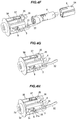
FIG.4A is an exploded perspective view showing a main part in the key cylinder device of the first embodiment at an assembly step; -
FIG.4B is an exploded perspective view showing the main part at an assembly step followingFIG.4A ; -
FIG.4C is an exploded perspective view showing the main part at an assembly step followingFIG.4B ; -
FIG.4D is an exploded perspective view showing the main part at an assembly step followingFIG.4C ; -
FIG.4E is an exploded perspective view showing the main part at an assembly step followingFIG.4D ; -
FIG.4F is an exploded perspective view showing the main part at an assembly step followingFIG.4E ; -
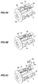
FIG.4G is a perspective view showing the last step in the assembly process of the key cylinder device; -
FIG.4H is a perspective view showing the completely assembled key cylinder device; -
FIG.5A is a cross sectional view partially showing the assembled situation of the device at the assembly step inFIG.4C ; -
FIG.5B is a cross sectional view partially showing the assembled situation of the device at the assembly step inFIG.4F ; -
FIG.5C is a cross sectional view partially showing the assembled situation of the completely assembled device; -
FIG.6A is a cross sectional view showing a stopper pin used in a key cylinder device in a second embodiment at an assembly step thereof; and -
FIG.6B is a cross sectional view showing the assembled stopper pin shown inFIG.6A . - Preferred embodiments of the invention will be described below in conjunction with the appended drawings. In the following description, front means a key insertion hole side of a key cylinder, rear means a rear side of the key insertion hole, and upper, lower, left and right are directions when viewing the key insertion hole from the front.
-
FIG.1 shows a configuration example of a typical key cylinder device in the first embodiment which is indicated generally by thereference numeral 1. Thekey cylinder device 1 is assembled into a steering lock device operable to prevent a rotating operation of a column shaft (not shown) when a vehicle is parked. - The
key cylinder device 1 in the illustrated example is provided with akey cylinder 2 capable of mechanical authentication of a mechanical key (not shown) (hereinafter, referred to as "key"). Thekey cylinder 2 is provided with acylindrical rotor case 3 and acolumnar rotor 4. Therotor case 3 has an opening at an end on the opposite side to akey insertion hole 4a into which a key is inserted. Therotor 4 is rotatably housed in therotor case 3. Therotor 4 is assembled to therotor case 3 in a direction opposite to a key insertion direction and this increases resistance of therotor 4 to pull-out from therotor case 3. - The
rotor 4 has thekey insertion hole 4a formed along a direction of a rotor rotation axis. Rotational operation of the key changes the position of therotor 4 between first to fourth positions which are an LOCK position, an ACC (accessory) position, an ON position and a START position in a clockwise direction as viewing thekey insertion hole 4a from the front. - The steering lock device is locked when the
rotor 4 is located at the LOCK position, and is unlocked when therotor 4 is located at any position from the ACC position to the START position. - The
rotor 4 is coupled to a camshaft which is a component of the steering lock device to operate an ignition switch (not shown). When therotor 4 is rotationally operated from the LOCK position through the ACC position to the ON position or the START position, connection of the contact point of the ignition switch is switched via the camshaft. Based on the connection state of the ignition switch changed by the switching operation, the status of various on-vehicle devices and an engine is switched. - As shown in
FIG.1 , therotor case 3 is formed of a cylindrical member with a circular flange-shaped case and has akey operation hole 3b on aflange portion 3a. A constituent material of therotor case 3 is, e.g., a metal material such as die-cast zinc. - Two
support walls 31 defining a recess therebetween along a key insertion direction are formed on an upper peripheral portion of therotor case 3, and a lockinglever 32 is pivotally supported between thesupport walls 31. The lockinglever 32 has, e.g., a key insertion detection function for detecting insertion of a key and a lock function for holding a locking member such as locking bar or lock stopper which enables or disables a rotating operation of the column shaft. - To the locking
lever 32, acoil spring 34 is attached in a state of being covered with acover plate 33 which is to be fixed to therotor case 3. The lockinglever 32 is pressed toward therotor 4 by a spring force of thecoil spring 34.Protrusions 31a formed to protrude from the outer surfaces of thesupport walls 31 on the right and left sides of therotor case 3 are snap-fitted into and fixed toholes 33b formed on a pair ofleg portions 33a on the both sides of thecover plate 33. - A
columnar stopper pin 35, which is a fixing member used to attach thekey cylinder 2 to a lock body (not shown), vertically movably penetrates the lower peripheral portion of therotor case 3. Thestopper pin 35 has a disc-shapedflange 35a. The outer surface of theflange 35a is fixed to the inside of astopper cover 36 as a holding member of which pair ofleg portions 36a on both sides are fixed to therotor case 3. The inner surface of theflange 35a is pressed toward the lock body by an elastic force of alever 37. - The
rotor case 3 is housed and fixed via a wobble-inhibiting rubber packing 6 inside the lock body which is formed of a metal material such as die-cast zinc. Therubber packing 6 is fitted and fixed to apacking holder 3c which is formed to protrude from a lock body-facing surface of therotor case 3, as shown inFIGS.4B and 4C . - As shown in
FIG.1 , therotor 4 has a shape with a step such that a largediameter rotor portion 41 having a key insertion detection function and a smalldiameter rotor portion 42 having a key checking function for checking a mechanical match of a key are integrally coupled with a level difference portion therebetween. - A
front cover 43 having a key insertion slot is housed in and fixed to a front opening of the largediameter rotor portion 41. A slidingpiece 44 is housed in the peripheral portion of the largediameter rotor portion 41 so as to be movable in a radial direction of the rotor when inserting/extracting the key. Abent piece 32a formed by bending a front end of the lockinglever 32 is arranged to face the outer surface of the slidingpiece 44. - Meanwhile,
plural tumblers 45 having a plate shape elongated in a radial direction and alocking piece 46 for preventing rotation of the camshaft are housed inside the smalldiameter rotor portion 42 so as to be resiliently retractable. A tumbler hole (not shown) to be engaged with a groove of the key is formed on eachtumbler 45. Thetumblers 45, when engaged with the key grooves through the tumbler holes, are thereby elastically held inside the smalldiameter rotor portion 42 at a predetermined position to be a key checking position for checking a mechanical match of the key. - In the state that the key is not inserted into the small
diameter rotor portion 42, protruding end portions of thetumblers 45 protrude beyond the outer peripheral surface of the smalldiameter rotor portion 42 and rotation of therotor 4 is restricted by engagement of the protruding end portions with the inner peripheral surface of therotor case 3. - In the state that the key is inserted into the
key insertion hole 4a, thetumblers 45 engaged with the grooves of the key all retract inward beyond the outer peripheral surface of therotor 4. As a result, therotor 4 can be rotationally operated without contact of anytumblers 45 with the inner peripheral surface of therotor case 3. - The shape and number of the
tumblers 45 are different depending on the shape of key, and therotor 4 needs to be changed according to the shape and number of thetumblers 45. Then, changing therotor 4 involves change of the shape of therotor case 3 since the key insertion detection function and the lock function of the lockinglever 32 are realized by the shape of therotor case 3. - Based on this, a
cylindrical metal sleeve 5 is used to allow therotor case 3 to have compatibility even when therotor 4 is changed to match a different shape of key. The position of thesleeve 5 to restrict rotation of therotor 4 is set to correspond to a changed key shape. By providing thesleeve 5 having a function of allowing therotor case 3 to have compatibility, it is possible to reduce the types of components. - Two
tumbler holding holes 51 having a long shape elongated in the direction of the rotor rotation axis and arranged side by side are formed on each of two opposing sides of thesleeve 5 so as to penetrate the peripheral portion of thesleeve 5. The tumbler holding holes 51 serve to allow the protruding end portions of the tumblers to be disengaged when the key is inserted, and to be engaged when the key is extracted. - The
sleeve 5 is formed to have a size (outer diameter) and a thickness which match the shape of a key to be used and the type and number, etc., of thetumblers 45, and the suitable number of thetumbler holding holes 51 having a suitable size and arranged at suitable positions are selected and used according to the shape of the key to be used and the type and number, etc., of thetumblers 45. It is therefore obvious that the positions and number, etc., of thetumbler holding holes 51 are not limited to those in the illustrated example. - The
rotor 4 is inserted into thesleeve 5 which is thus placed around the outer peripheral surface of the smalldiameter rotor portion 42 as shown inFIGS.1 to 3 , and thekey cylinder 2 has a multiple cylindrical wall structure composed of therotor case 3, therotor 4 and thesleeve 5.Guide ribs 52 extending and tapering in the insertion direction are formed to protrude from the outer peripheral surface of thesleeve 5 at two opposing positions and are inserted into and fixed to guiderecesses 3d formed on the inner peripheral surface of therotor case 3. - An opening end face 53 located on the front side of the
sleeve 5 is configured as a stopping surface which comes into contact with anannular step surface 4b formed between the largediameter rotor portion 41 and the smalldiameter rotor portion 42 and also with an annular steppedportion 3e formed on the inner peripheral surface of therotor case 3 and located behind theflange portion 3a, and thereby prevents therotor 4 from being pulled out. - As shown in
FIGS.2, 3 and4F , a rhombus-shapedlocking hole 54 for fitting and fixing thestopper pin 35 is formed to penetrate a rear end portion of thesleeve 5. The lockinghole 54 is configured as a stopping portion to which thestopper pin 35 penetrating the lower peripheral portion of therotor case 3 is fitted and which thereby prevents the pull-out. - The
key cylinder device 1 configured as described above has a rear-side assembly structure that therotor 4 and thesleeve 5 are assembled into therotor case 3 from a direction opposite to the key insertion direction. As in prior art, without the stopper pin holding structure according to the invention, thestopper pin 35 cannot be fitted and fixed to the rear end portion of thesleeve 5 through the outer surface of therotor case 3 before therotor 4 and thesleeve 5 are assembled into the inside of therotor case 3. Thus, the conventional assembly process will be restricted by the assembly sequence of thekey cylinder 2. - By contrast, according to the invention, a stopper pin holding structure is used that allows an arbitrary assembly sequence without the restriction of the assembly sequence of the
key cylinder 2. In the illustrated example, therotor case 3 has a fixing member-holding structure in which thestopper pin 35 is held, via thestopper cover 36, at a temporary assembly position for temporary assembly with a distance from thesleeve 5, and then at an assembly position for assembly to the lockinghole 54 of thesleeve 5. - As shown in
FIGS.1 to 3 , the stopper pin holding structure is provided with twovertical walls 38 formed upright on the outer surface of therotor case 3 and defining a recess therebetween, and protrudingportions 38a each composed of a pair of vertically intermittently arranged protrusions and formed to protrude respectively from the outer surfaces of thevertical walls 38 on the right and left sides of the recess. - The
stopper pin 35 is arranged through a through-hole 3f formed in the recess defined between thevertical walls 38 so as to penetrate therotor case 3 from the outer surface to the inner surface, and the pair ofleg portions 36a of thestopper cover 36 to which thestopper pin 35 is inserted and fixed are held by the protrudingportions 38a of thevertical walls 38 defining a recess. - The protruding
portion 38a of therotor case 3 is composed of atemporary holding portion 38b for temporarily holding thestopper pin 35 via thestopper cover 36, and a holdingportion 38c located below the peak position of thetemporary holding portion 38b so as to protrude outward beyond the peak position of thetemporary holding portion 38b. Thetemporary holding portion 38b is the temporary assembly position for assembling thestopper pin 35 with a distance from thesleeve 5, while the holdingportion 38c is the assembly position for assembling thestopper pin 35 to the lockinghole 54 of thesleeve 5. - Each of the
temporary holding portion 38b and the holdingportion 38c is formed of a triangular block extending throughout substantially the entire width of thestopper cover 36. In addition, in each protrudingportion 38a, surfaces of thetemporary holding portion 38b and the holdingportion 38c on the stopper cover insertion side are respectively formed as guide surfaces 38d and 38e which are inclined downward. - Meanwhile, the
stopper cover 36 is formed of, e.g., an elastic resin material and has lockinghooks 36b on inner surfaces of the front end portions of the pair ofleg portions 36a. A distance between pointed tips of the pair of lockinghooks 36b is smaller than distances between the peaks of the pair oftemporary holding portions 38b and between the peaks of the pair of holdingportions 38c of therotor case 3. - Therefore, when the
leg portions 36a of thestopper cover 36 pass beyond the guide surfaces 38d of thetemporary holding portions 38b of therotor case 3, theleg portions 36a once elastically stretched open return to the original shape and the locking hooks 36b of thestopper cover 36 are temporarily locked to the rims of thetemporary holding portions 38b on the back side. At this time, thestopper pin 35 is located at the temporary assembly position for temporary assembly in a retracted state without inwardly protruding beyond the inner surface of therotor case 3 and is not fitted and fixed to the lockinghole 54 of thesleeve 5. - When the
leg portions 36a of thestopper cover 36 leaves the rims on the back side of thetemporary holding portions 38b of therotor case 3 and then pass beyond the guide surfaces 38e of the holdingportions 38c, theleg portions 36a once elastically stretched open return to the original shape and the locking hooks 36b of thestopper cover 36 are locked to the holdingportions 38c on the back side. At this time, thestopper pin 35 is located at the assembly position for assembly in a state of inwardly protruding from the inner surface of therotor case 3 and is fitted and fixed to the lockinghole 54 of thesleeve 5. - When assembling the
key cylinder 2 configured as described above, a stopper pin temporary assembly step for temporarily assembling thestopper pin 35 to therotor case 3 is performed before assembling therotor 4 and thesleeve 5 to therotor case 3, as shown inFIGS.4A to 5C . - To assemble the
key cylinder 2, firstly, anattachment hole 37a of thelever 37 is fixed to anattachment pin 3g formed to protrude between the recess-shapedvertical walls 38 of therotor case 3, as shown inFIG.4A . - Next, as shown in
FIG.4B , therubber packing 6 is fitted and fixed to thepacking holder 3c of therotor case 3. - Next, as shown in
FIG.4C , thestopper pin 35 is fitted to thestopper cover 36. Before assembling therotor 4 and thesleeve 5 to the inside of therotor case 3, thestopper pin 35 and thestopper cover 36 are inserted between thevertical walls 38 of therotor case 3 via a tip of thelever 37. - When the
stopper cover 36 is pushed down, the locking hooks 36b of thestopper cover 36 are temporarily locked to the rims on the back side of thetemporary holding portions 38b of therotor case 3, as shown inFIG.5A . At this time, an end portion of thestopper pin 35 is temporarily held at a predetermined position in the through-hole 3f of therotor case 3. - Next, as shown in
FIG.4D , after therotor case 3 is flipped over, thecoil spring 34 is inserted between thesupport walls 31 of therotor case 3 and theprotrusions 31a of therotor case 3 are snap-fitted into theholes 33b of thecover plate 33 against the spring force of thecoil spring 34. - Next, as shown in
FIG.4E , the lockinglever 32 is inserted so as to be supported between thesupport walls 31 of therotor case 3. - Next, as shown in
FIG.4F , after therotor case 3 is flipped over again and thesleeve 5 is assembled to therotor 4, therotor 4 and thesleeve 5 are assembled to the inside of therotor case 3 from a direction opposite to the key insertion direction. Once therotor 4 and thesleeve 5 are assembled, the lockinghole 54 of thesleeve 5 is arranged at a position corresponding to thestopper pin 35, as shown inFIG.5B . - Next, as shown in
FIGS.4G and 4H , thestopper cover 36 is pushed down while sandwiching thevertical walls 38. When thestopper cover 36 is pushed down, theleg portions 36a of thestopper cover 36 are locked to the holdingportions 38c on the back side, as shown inFIG.5C . Thestopper pin 35 is fitted and fixed to the lockinghole 54 of thesleeve 5. - The completely assembled
key cylinder 2 shown inFIG.4H is obtained through a series of the assembly steps described above. - The
key cylinder device 1 configured as described above exerts the following effects, in addition to the effects described above. - (1) The
stopper pin 35 and thestopper cover 36 can be assembled into therotor case 3 in a step prior to assembling therotor 4 and thesleeve 5 into therotor case 3. (2) The degree of freedom of the assembly sequence increases, allowing the assembly process to be shortened and the manufacturing cost to be reduced. -
FIGS.6A and 6B show an assembly step and an assembled situation of the stopper pin which is used in a key cylinder device in the second embodiment. Members which are substantially the same as those in the first embodiment are denoted by the same names and reference numerals inFIGS.6A and 6B and the detailed explanation for such members will be omitted. - In the stopper pin holding structure of the first embodiment, the protruding
portions 38a having plural steps are respectively arranged on the outer surfaces of thevertical walls 38 formed upright on the outer surface of therotor case 3 and defining a recess therebetween. The second embodiment is different from the first embodiment in that the stopper pin holding structure is configured such that a single protrudingportion 38f is arranged on the outer surface of eachvertical wall 38 of therotor case 3. - The stopper pin holding structure in
FIGS.6A and 6B is provided with a pair of protrudingportions 38f respectively formed on the outer surfaces of thevertical walls 38 of therotor case 3 on the right and left sides of the recess. Each protrudingportion 38f is formed of a triangular block having aguide surface 38g and aninclined surface 38h. Theguide surface 38g is a surface on the stopper cover insertion side and is inclined downward. Theinclined surface 38h is continued from the peak position of theguide surface 38g and is inclined inward and downward. The protrudingportion 38f is formed to extend throughout substantially the entire width of thestopper cover 36. - A distance between the pointed tips of the locking hooks 36b of the
stopper cover 36 is smaller than a distance between the peaks of the pair of the protrudingportions 38f of therotor case 3. Therefore, when theleg portions 36a of thestopper cover 36 reach the peak positions of the guide surfaces 38g of the protrudingportions 38f of therotor case 3, the locking hooks 36b of thestopper cover 36 are temporarily locked to theinclined surfaces 38h at a position near and below the peak positions in a state of being open. - When the
leg portions 36a of thestopper cover 36 pass through theinclined surfaces 38h below the peak positions of the protrudingportions 38f of therotor case 3, theleg portions 36a once elastically stretched open return to the original shape and the locking hooks 36b of thestopper cover 36 are locked to thevertical walls 38 at the lower edges of theinclined surfaces 38h of the protrudingportions 38f. - The
key cylinder device 1 in the second embodiment exerts the following effects, in addition to the effects of the first embodiment. - It is possible to simplify the shape of the
vertical wall 38 of therotor case 3 used for the stopper pin holding structure, and also to reduce the weight of thekey cylinder 2. - Although, in the typical configuration example of the invention, the stopper pin holding structure is applied to the
key cylinder device 1 in which thesleeve 5 placed around therotor 4 and fixed to the inner surface of therotor case 3 is provided to allow therotor case 3 to have compatibility, the invention is not limited thereto. The stopper pin holding structure can be effectively applied to thekey cylinder device 1 configured so that, e.g., therotor 4 is rotatably housed in therotor case 3 without providing thesleeve 5. - In addition, although the
key cylinder device 1 is applied to a car in the typical configuration example of the invention, it is not limited thereto. It is obvious that the invention can be effectively applied to, e.g., various vehicles such as construction machineries and agricultural machineries. - It is obvious from the above description that the invention according to claims is not to be limited to the typical embodiments and illustrated examples of the invention. Therefore, it should be noted that all combinations of the features described in the embodiments and illustrated examples are not necessary to solve the problem of the invention.
Claims (5)
- A key cylinder device, comprising:a rotor case that encloses a rotor operable to rotate by a mechanical key, the rotor being inserted into the rotor case from a direction opposite to an insertion direction of the mechanical key;a holding member comprising a pair of leg portions held by the rotor case; anda fixing member that protrudes from the holding member,wherein the rotor case comprises a fixing member-holding structure that the fixing member is held by the leg portions of the holding member at a temporary assembly position for temporarily assembling the fixing member in a retracted state without inwardly protruding beyond an inner surface of the rotor case and at an assembly position for assembling the fixing member in a state of inwardly protruding from the inner surface of the rotor case.
- The key cylinder device according to claim 1, wherein the fixing member-holding structure comprises a pair of vertical walls and a protruding portion horizontally protruding from each of the vertical walls,wherein the pair of vertical walls are formed upright on an outer surface of the rotor case such that the fixing member is arranged between the vertical walls while penetrating the rotor case from the outer surface to the inner surface, andwherein the protruding portion is configured such that the leg portions of the holding member are held by at the temporary assembly position and at the assembly position.
- The key cylinder device according to claim 2, wherein the protruding portion comprises first and second protrusions that are arranged vertically intermittently and are formed to protrude from the outer surface of each vertical wall,wherein the first protrusion is formed as a temporary holding member to temporarily hold the leg portion of the holding member at the temporary assembly position, andwherein the second protrusion is formed as a holding member to hold the leg portion of the holding member at the assembly position.
- The key cylinder device according to claim 2, wherein the protruding portion comprises a single protruding portion comprising a guide surface inclined downward and an inclined surface continued from the peak position of the guide surface and inclined inward and downward, and the inclined surface is formed as a temporary holding member to temporarily hold the leg portion of the holding member at the temporary assembly position.
- The key cylinder device according to any of the preceding claims, further comprising a sleeve between the rotor and the rotor case,wherein the fixing member is withdrawn from a locking hole formed in the sleeve at the temporary assembly position so as to allow an insertion of the sleeve into the rotor case and inserted into the locking hole at the assembly position so as to prevent a separation of the sleeve from the rotor case.
Applications Claiming Priority (1)
| Application Number | Priority Date | Filing Date | Title |
|---|---|---|---|
| JP2015010290A JP5925921B1 (en) | 2015-01-22 | 2015-01-22 | Key cylinder device |
Publications (2)
| Publication Number | Publication Date |
|---|---|
| EP3051043A1 true EP3051043A1 (en) | 2016-08-03 |
| EP3051043B1 EP3051043B1 (en) | 2018-03-28 |
Family
ID=55177853
Family Applications (1)
| Application Number | Title | Priority Date | Filing Date |
|---|---|---|---|
| EP16151989.7A Not-in-force EP3051043B1 (en) | 2015-01-22 | 2016-01-20 | Key cylinder device |
Country Status (4)
| Country | Link |
|---|---|
| US (1) | US10017961B2 (en) |
| EP (1) | EP3051043B1 (en) |
| JP (1) | JP5925921B1 (en) |
| CN (1) | CN105822157B (en) |
Citations (6)
| Publication number | Priority date | Publication date | Assignee | Title |
|---|---|---|---|---|
| JP2001098800A (en) * | 1999-09-30 | 2001-04-10 | Yuhshin Co Ltd | Mounting structure of cylinder lock in key cylinder device |
| US6364586B1 (en) * | 1999-09-02 | 2002-04-02 | Piolax Inc. | Multiple locking position clip with grommet and pin |
| JP3346706B2 (en) | 1996-06-14 | 2002-11-18 | 株式会社ユーシン | Steering lock device |
| EP1375931A1 (en) * | 2002-06-12 | 2004-01-02 | Piolax Inc. | Two-piece clip |
| JP2004263441A (en) * | 2003-03-03 | 2004-09-24 | Yuhshin Co Ltd | Steering lock device |
| JP2004262337A (en) * | 2003-02-28 | 2004-09-24 | Yuhshin Co Ltd | Steering lock device with interlock mechanism |
Family Cites Families (11)
| Publication number | Priority date | Publication date | Assignee | Title |
|---|---|---|---|---|
| DE2028475A1 (en) * | 1970-06-10 | 1971-12-16 | Josef Voss KG, 5040 Brühl | Steering lock, in particular for motor vehicles |
| DE2047054A1 (en) * | 1970-09-24 | 1972-03-30 | Voss Kg J | Steering lock, in particular for motor vehicles |
| JPH0643970Y2 (en) * | 1988-11-10 | 1994-11-14 | 株式会社東海理化電機製作所 | Ignition key device |
| JP2904692B2 (en) * | 1993-11-30 | 1999-06-14 | 株式会社ユーシン | Freewheel cylinder lock |
| JP3095328B2 (en) * | 1994-10-06 | 2000-10-03 | 株式会社東海理化電機製作所 | Steering lock device |
| US6442985B1 (en) * | 1999-06-11 | 2002-09-03 | Nissan Motor Co., Ltd. | Lock apparatus and lock system |
| GB2376044B (en) * | 2001-06-01 | 2005-05-25 | Tokai Rika Co Ltd | Steering wheel locking device |
| JP5500797B2 (en) * | 2008-07-29 | 2014-05-21 | 株式会社東海理化電機製作所 | Key device |
| FR2937600B1 (en) * | 2008-10-23 | 2010-11-12 | Valeo Securite Habitacle | MOTOR VEHICLE ANTI-THEFT LOCK |
| CN104124093B (en) * | 2013-04-26 | 2018-07-31 | 株式会社有信 | Lenkradschlossvorrichtung |
| JP6042459B2 (en) * | 2015-01-07 | 2016-12-14 | 株式会社東海理化電機製作所 | Key cylinder device |
-
2015
- 2015-01-22 JP JP2015010290A patent/JP5925921B1/en active Active
- 2015-12-28 CN CN201510999122.0A patent/CN105822157B/en active Active
-
2016
- 2016-01-20 US US15/001,928 patent/US10017961B2/en active Active
- 2016-01-20 EP EP16151989.7A patent/EP3051043B1/en not_active Not-in-force
Patent Citations (6)
| Publication number | Priority date | Publication date | Assignee | Title |
|---|---|---|---|---|
| JP3346706B2 (en) | 1996-06-14 | 2002-11-18 | 株式会社ユーシン | Steering lock device |
| US6364586B1 (en) * | 1999-09-02 | 2002-04-02 | Piolax Inc. | Multiple locking position clip with grommet and pin |
| JP2001098800A (en) * | 1999-09-30 | 2001-04-10 | Yuhshin Co Ltd | Mounting structure of cylinder lock in key cylinder device |
| EP1375931A1 (en) * | 2002-06-12 | 2004-01-02 | Piolax Inc. | Two-piece clip |
| JP2004262337A (en) * | 2003-02-28 | 2004-09-24 | Yuhshin Co Ltd | Steering lock device with interlock mechanism |
| JP2004263441A (en) * | 2003-03-03 | 2004-09-24 | Yuhshin Co Ltd | Steering lock device |
Also Published As
| Publication number | Publication date |
|---|---|
| US20160215522A1 (en) | 2016-07-28 |
| JP5925921B1 (en) | 2016-05-25 |
| CN105822157B (en) | 2018-01-23 |
| EP3051043B1 (en) | 2018-03-28 |
| JP2016132966A (en) | 2016-07-25 |
| US10017961B2 (en) | 2018-07-10 |
| CN105822157A (en) | 2016-08-03 |
Similar Documents
| Publication | Publication Date | Title |
|---|---|---|
| EP3106592B1 (en) | Key cylinder device | |
| US11814881B2 (en) | Vehicle glove box latch | |
| US9217453B2 (en) | Mounting structure for parts | |
| US12331564B2 (en) | Vehicle glove box latch | |
| US9278669B2 (en) | Steering lock device | |
| US10099654B2 (en) | Anti-theft device for a motor vehicle steering column | |
| EP2982548B1 (en) | Steering lock device | |
| US9745776B2 (en) | Key cylinder device | |
| EP3051043B1 (en) | Key cylinder device | |
| EP3042808B1 (en) | Key cylinder device | |
| EP3081724A1 (en) | Cylinder locking device | |
| JP2016536207A (en) | Anti-theft device for automobile steering column | |
| KR20150111619A (en) | Locking device for opening and closing body | |
| US20210284097A1 (en) | Device for removably mounting an airbag module | |
| US20160023633A1 (en) | Steering lock device | |
| KR20170001038U (en) | The car anti-theft device | |
| JP2004263441A (en) | Steering lock device |
Legal Events
| Date | Code | Title | Description |
|---|---|---|---|
| PUAI | Public reference made under article 153(3) epc to a published international application that has entered the european phase |
Free format text: ORIGINAL CODE: 0009012 |
|
| AK | Designated contracting states |
Kind code of ref document: A1 Designated state(s): AL AT BE BG CH CY CZ DE DK EE ES FI FR GB GR HR HU IE IS IT LI LT LU LV MC MK MT NL NO PL PT RO RS SE SI SK SM TR |
|
| AX | Request for extension of the european patent |
Extension state: BA ME |
|
| STAA | Information on the status of an ep patent application or granted ep patent |
Free format text: STATUS: REQUEST FOR EXAMINATION WAS MADE |
|
| 17P | Request for examination filed |
Effective date: 20170203 |
|
| RBV | Designated contracting states (corrected) |
Designated state(s): AL AT BE BG CH CY CZ DE DK EE ES FI FR GB GR HR HU IE IS IT LI LT LU LV MC MK MT NL NO PL PT RO RS SE SI SK SM TR |
|
| GRAP | Despatch of communication of intention to grant a patent |
Free format text: ORIGINAL CODE: EPIDOSNIGR1 |
|
| STAA | Information on the status of an ep patent application or granted ep patent |
Free format text: STATUS: GRANT OF PATENT IS INTENDED |
|
| RIC1 | Information provided on ipc code assigned before grant |
Ipc: E05B 27/00 20060101ALI20171031BHEP Ipc: E05B 9/08 20060101AFI20171031BHEP Ipc: E05B 15/14 20060101ALI20171031BHEP Ipc: E05B 9/04 20060101ALI20171031BHEP |
|
| INTG | Intention to grant announced |
Effective date: 20171130 |
|
| GRAS | Grant fee paid |
Free format text: ORIGINAL CODE: EPIDOSNIGR3 |
|
| GRAA | (expected) grant |
Free format text: ORIGINAL CODE: 0009210 |
|
| STAA | Information on the status of an ep patent application or granted ep patent |
Free format text: STATUS: THE PATENT HAS BEEN GRANTED |
|
| AK | Designated contracting states |
Kind code of ref document: B1 Designated state(s): AL AT BE BG CH CY CZ DE DK EE ES FI FR GB GR HR HU IE IS IT LI LT LU LV MC MK MT NL NO PL PT RO RS SE SI SK SM TR |
|
| REG | Reference to a national code |
Ref country code: GB Ref legal event code: FG4D |
|
| REG | Reference to a national code |
Ref country code: CH Ref legal event code: EP |
|
| REG | Reference to a national code |
Ref country code: AT Ref legal event code: REF Ref document number: 983591 Country of ref document: AT Kind code of ref document: T Effective date: 20180415 |
|
| REG | Reference to a national code |
Ref country code: IE Ref legal event code: FG4D |
|
| REG | Reference to a national code |
Ref country code: DE Ref legal event code: R096 Ref document number: 602016002159 Country of ref document: DE |
|
| PG25 | Lapsed in a contracting state [announced via postgrant information from national office to epo] |
Ref country code: NO Free format text: LAPSE BECAUSE OF FAILURE TO SUBMIT A TRANSLATION OF THE DESCRIPTION OR TO PAY THE FEE WITHIN THE PRESCRIBED TIME-LIMIT Effective date: 20180628 Ref country code: FI Free format text: LAPSE BECAUSE OF FAILURE TO SUBMIT A TRANSLATION OF THE DESCRIPTION OR TO PAY THE FEE WITHIN THE PRESCRIBED TIME-LIMIT Effective date: 20180328 Ref country code: HR Free format text: LAPSE BECAUSE OF FAILURE TO SUBMIT A TRANSLATION OF THE DESCRIPTION OR TO PAY THE FEE WITHIN THE PRESCRIBED TIME-LIMIT Effective date: 20180328 Ref country code: LT Free format text: LAPSE BECAUSE OF FAILURE TO SUBMIT A TRANSLATION OF THE DESCRIPTION OR TO PAY THE FEE WITHIN THE PRESCRIBED TIME-LIMIT Effective date: 20180328 |
|
| REG | Reference to a national code |
Ref country code: NL Ref legal event code: MP Effective date: 20180328 |
|
| REG | Reference to a national code |
Ref country code: LT Ref legal event code: MG4D |
|
| PG25 | Lapsed in a contracting state [announced via postgrant information from national office to epo] |
Ref country code: LV Free format text: LAPSE BECAUSE OF FAILURE TO SUBMIT A TRANSLATION OF THE DESCRIPTION OR TO PAY THE FEE WITHIN THE PRESCRIBED TIME-LIMIT Effective date: 20180328 Ref country code: GR Free format text: LAPSE BECAUSE OF FAILURE TO SUBMIT A TRANSLATION OF THE DESCRIPTION OR TO PAY THE FEE WITHIN THE PRESCRIBED TIME-LIMIT Effective date: 20180629 Ref country code: BG Free format text: LAPSE BECAUSE OF FAILURE TO SUBMIT A TRANSLATION OF THE DESCRIPTION OR TO PAY THE FEE WITHIN THE PRESCRIBED TIME-LIMIT Effective date: 20180628 Ref country code: RS Free format text: LAPSE BECAUSE OF FAILURE TO SUBMIT A TRANSLATION OF THE DESCRIPTION OR TO PAY THE FEE WITHIN THE PRESCRIBED TIME-LIMIT Effective date: 20180328 Ref country code: SE Free format text: LAPSE BECAUSE OF FAILURE TO SUBMIT A TRANSLATION OF THE DESCRIPTION OR TO PAY THE FEE WITHIN THE PRESCRIBED TIME-LIMIT Effective date: 20180328 |
|
| PG25 | Lapsed in a contracting state [announced via postgrant information from national office to epo] |
Ref country code: EE Free format text: LAPSE BECAUSE OF FAILURE TO SUBMIT A TRANSLATION OF THE DESCRIPTION OR TO PAY THE FEE WITHIN THE PRESCRIBED TIME-LIMIT Effective date: 20180328 Ref country code: ES Free format text: LAPSE BECAUSE OF FAILURE TO SUBMIT A TRANSLATION OF THE DESCRIPTION OR TO PAY THE FEE WITHIN THE PRESCRIBED TIME-LIMIT Effective date: 20180328 Ref country code: PL Free format text: LAPSE BECAUSE OF FAILURE TO SUBMIT A TRANSLATION OF THE DESCRIPTION OR TO PAY THE FEE WITHIN THE PRESCRIBED TIME-LIMIT Effective date: 20180328 Ref country code: RO Free format text: LAPSE BECAUSE OF FAILURE TO SUBMIT A TRANSLATION OF THE DESCRIPTION OR TO PAY THE FEE WITHIN THE PRESCRIBED TIME-LIMIT Effective date: 20180328 Ref country code: NL Free format text: LAPSE BECAUSE OF FAILURE TO SUBMIT A TRANSLATION OF THE DESCRIPTION OR TO PAY THE FEE WITHIN THE PRESCRIBED TIME-LIMIT Effective date: 20180328 Ref country code: AL Free format text: LAPSE BECAUSE OF FAILURE TO SUBMIT A TRANSLATION OF THE DESCRIPTION OR TO PAY THE FEE WITHIN THE PRESCRIBED TIME-LIMIT Effective date: 20180328 |
|
| PG25 | Lapsed in a contracting state [announced via postgrant information from national office to epo] |
Ref country code: CZ Free format text: LAPSE BECAUSE OF FAILURE TO SUBMIT A TRANSLATION OF THE DESCRIPTION OR TO PAY THE FEE WITHIN THE PRESCRIBED TIME-LIMIT Effective date: 20180328 Ref country code: SM Free format text: LAPSE BECAUSE OF FAILURE TO SUBMIT A TRANSLATION OF THE DESCRIPTION OR TO PAY THE FEE WITHIN THE PRESCRIBED TIME-LIMIT Effective date: 20180328 Ref country code: SK Free format text: LAPSE BECAUSE OF FAILURE TO SUBMIT A TRANSLATION OF THE DESCRIPTION OR TO PAY THE FEE WITHIN THE PRESCRIBED TIME-LIMIT Effective date: 20180328 |
|
| REG | Reference to a national code |
Ref country code: AT Ref legal event code: MK05 Ref document number: 983591 Country of ref document: AT Kind code of ref document: T Effective date: 20180328 |
|
| PG25 | Lapsed in a contracting state [announced via postgrant information from national office to epo] |
Ref country code: PT Free format text: LAPSE BECAUSE OF FAILURE TO SUBMIT A TRANSLATION OF THE DESCRIPTION OR TO PAY THE FEE WITHIN THE PRESCRIBED TIME-LIMIT Effective date: 20180730 |
|
| REG | Reference to a national code |
Ref country code: DE Ref legal event code: R097 Ref document number: 602016002159 Country of ref document: DE |
|
| PG25 | Lapsed in a contracting state [announced via postgrant information from national office to epo] |
Ref country code: AT Free format text: LAPSE BECAUSE OF FAILURE TO SUBMIT A TRANSLATION OF THE DESCRIPTION OR TO PAY THE FEE WITHIN THE PRESCRIBED TIME-LIMIT Effective date: 20180328 Ref country code: DK Free format text: LAPSE BECAUSE OF FAILURE TO SUBMIT A TRANSLATION OF THE DESCRIPTION OR TO PAY THE FEE WITHIN THE PRESCRIBED TIME-LIMIT Effective date: 20180328 |
|
| PLBE | No opposition filed within time limit |
Free format text: ORIGINAL CODE: 0009261 |
|
| STAA | Information on the status of an ep patent application or granted ep patent |
Free format text: STATUS: NO OPPOSITION FILED WITHIN TIME LIMIT |
|
| PG25 | Lapsed in a contracting state [announced via postgrant information from national office to epo] |
Ref country code: IT Free format text: LAPSE BECAUSE OF FAILURE TO SUBMIT A TRANSLATION OF THE DESCRIPTION OR TO PAY THE FEE WITHIN THE PRESCRIBED TIME-LIMIT Effective date: 20180328 |
|
| 26N | No opposition filed |
Effective date: 20190103 |
|
| PG25 | Lapsed in a contracting state [announced via postgrant information from national office to epo] |
Ref country code: SI Free format text: LAPSE BECAUSE OF FAILURE TO SUBMIT A TRANSLATION OF THE DESCRIPTION OR TO PAY THE FEE WITHIN THE PRESCRIBED TIME-LIMIT Effective date: 20180328 |
|
| PG25 | Lapsed in a contracting state [announced via postgrant information from national office to epo] |
Ref country code: MC Free format text: LAPSE BECAUSE OF FAILURE TO SUBMIT A TRANSLATION OF THE DESCRIPTION OR TO PAY THE FEE WITHIN THE PRESCRIBED TIME-LIMIT Effective date: 20180328 |
|
| REG | Reference to a national code |
Ref country code: CH Ref legal event code: PL |
|
| PG25 | Lapsed in a contracting state [announced via postgrant information from national office to epo] |
Ref country code: LU Free format text: LAPSE BECAUSE OF NON-PAYMENT OF DUE FEES Effective date: 20190120 |
|
| REG | Reference to a national code |
Ref country code: BE Ref legal event code: MM Effective date: 20190131 |
|
| REG | Reference to a national code |
Ref country code: IE Ref legal event code: MM4A |
|
| PG25 | Lapsed in a contracting state [announced via postgrant information from national office to epo] |
Ref country code: BE Free format text: LAPSE BECAUSE OF NON-PAYMENT OF DUE FEES Effective date: 20190131 |
|
| PG25 | Lapsed in a contracting state [announced via postgrant information from national office to epo] |
Ref country code: LI Free format text: LAPSE BECAUSE OF NON-PAYMENT OF DUE FEES Effective date: 20190131 Ref country code: CH Free format text: LAPSE BECAUSE OF NON-PAYMENT OF DUE FEES Effective date: 20190131 |
|
| PG25 | Lapsed in a contracting state [announced via postgrant information from national office to epo] |
Ref country code: IE Free format text: LAPSE BECAUSE OF NON-PAYMENT OF DUE FEES Effective date: 20190120 |
|
| PGFP | Annual fee paid to national office [announced via postgrant information from national office to epo] |
Ref country code: FR Payment date: 20191216 Year of fee payment: 5 |
|
| PG25 | Lapsed in a contracting state [announced via postgrant information from national office to epo] |
Ref country code: TR Free format text: LAPSE BECAUSE OF FAILURE TO SUBMIT A TRANSLATION OF THE DESCRIPTION OR TO PAY THE FEE WITHIN THE PRESCRIBED TIME-LIMIT Effective date: 20180328 |
|
| PGFP | Annual fee paid to national office [announced via postgrant information from national office to epo] |
Ref country code: GB Payment date: 20200113 Year of fee payment: 5 |
|
| PG25 | Lapsed in a contracting state [announced via postgrant information from national office to epo] |
Ref country code: MT Free format text: LAPSE BECAUSE OF NON-PAYMENT OF DUE FEES Effective date: 20190120 |
|
| PG25 | Lapsed in a contracting state [announced via postgrant information from national office to epo] |
Ref country code: CY Free format text: LAPSE BECAUSE OF FAILURE TO SUBMIT A TRANSLATION OF THE DESCRIPTION OR TO PAY THE FEE WITHIN THE PRESCRIBED TIME-LIMIT Effective date: 20180328 |
|
| PG25 | Lapsed in a contracting state [announced via postgrant information from national office to epo] |
Ref country code: IS Free format text: LAPSE BECAUSE OF FAILURE TO SUBMIT A TRANSLATION OF THE DESCRIPTION OR TO PAY THE FEE WITHIN THE PRESCRIBED TIME-LIMIT Effective date: 20180728 |
|
| PG25 | Lapsed in a contracting state [announced via postgrant information from national office to epo] |
Ref country code: HU Free format text: LAPSE BECAUSE OF FAILURE TO SUBMIT A TRANSLATION OF THE DESCRIPTION OR TO PAY THE FEE WITHIN THE PRESCRIBED TIME-LIMIT; INVALID AB INITIO Effective date: 20160120 |
|
| GBPC | Gb: european patent ceased through non-payment of renewal fee |
Effective date: 20210120 |
|
| PG25 | Lapsed in a contracting state [announced via postgrant information from national office to epo] |
Ref country code: FR Free format text: LAPSE BECAUSE OF NON-PAYMENT OF DUE FEES Effective date: 20210131 |
|
| PG25 | Lapsed in a contracting state [announced via postgrant information from national office to epo] |
Ref country code: GB Free format text: LAPSE BECAUSE OF NON-PAYMENT OF DUE FEES Effective date: 20210120 |
|
| PG25 | Lapsed in a contracting state [announced via postgrant information from national office to epo] |
Ref country code: MK Free format text: LAPSE BECAUSE OF FAILURE TO SUBMIT A TRANSLATION OF THE DESCRIPTION OR TO PAY THE FEE WITHIN THE PRESCRIBED TIME-LIMIT Effective date: 20180328 |
|
| PGFP | Annual fee paid to national office [announced via postgrant information from national office to epo] |
Ref country code: DE Payment date: 20221130 Year of fee payment: 8 |
|
| REG | Reference to a national code |
Ref country code: DE Ref legal event code: R119 Ref document number: 602016002159 Country of ref document: DE |
|
| PG25 | Lapsed in a contracting state [announced via postgrant information from national office to epo] |
Ref country code: DE Free format text: LAPSE BECAUSE OF NON-PAYMENT OF DUE FEES Effective date: 20240801 |
|
| PG25 | Lapsed in a contracting state [announced via postgrant information from national office to epo] |
Ref country code: DE Free format text: LAPSE BECAUSE OF NON-PAYMENT OF DUE FEES Effective date: 20240801 |