EP3051032A2 - Lifting arrangement for a construction machine - Google Patents
Lifting arrangement for a construction machine Download PDFInfo
- Publication number
- EP3051032A2 EP3051032A2 EP15162500.1A EP15162500A EP3051032A2 EP 3051032 A2 EP3051032 A2 EP 3051032A2 EP 15162500 A EP15162500 A EP 15162500A EP 3051032 A2 EP3051032 A2 EP 3051032A2
- Authority
- EP
- European Patent Office
- Prior art keywords
- main arm
- lifting
- actuating element
- arrangement
- construction machine
- Prior art date
- Legal status (The legal status is an assumption and is not a legal conclusion. Google has not performed a legal analysis and makes no representation as to the accuracy of the status listed.)
- Granted
Links
Images


Classifications
-
- E—FIXED CONSTRUCTIONS
- E02—HYDRAULIC ENGINEERING; FOUNDATIONS; SOIL SHIFTING
- E02F—DREDGING; SOIL-SHIFTING
- E02F3/00—Dredgers; Soil-shifting machines
- E02F3/04—Dredgers; Soil-shifting machines mechanically-driven
- E02F3/28—Dredgers; Soil-shifting machines mechanically-driven with digging tools mounted on a dipper- or bucket-arm, i.e. there is either one arm or a pair of arms, e.g. dippers, buckets
- E02F3/36—Component parts
- E02F3/42—Drives for dippers, buckets, dipper-arms or bucket-arms
- E02F3/43—Control of dipper or bucket position; Control of sequence of drive operations
- E02F3/431—Control of dipper or bucket position; Control of sequence of drive operations for bucket-arms, front-end loaders, dumpers or the like
- E02F3/434—Control of dipper or bucket position; Control of sequence of drive operations for bucket-arms, front-end loaders, dumpers or the like providing automatic sequences of movements, e.g. automatic dumping or loading, automatic return-to-dig
-
- E—FIXED CONSTRUCTIONS
- E02—HYDRAULIC ENGINEERING; FOUNDATIONS; SOIL SHIFTING
- E02F—DREDGING; SOIL-SHIFTING
- E02F3/00—Dredgers; Soil-shifting machines
- E02F3/04—Dredgers; Soil-shifting machines mechanically-driven
- E02F3/28—Dredgers; Soil-shifting machines mechanically-driven with digging tools mounted on a dipper- or bucket-arm, i.e. there is either one arm or a pair of arms, e.g. dippers, buckets
- E02F3/34—Dredgers; Soil-shifting machines mechanically-driven with digging tools mounted on a dipper- or bucket-arm, i.e. there is either one arm or a pair of arms, e.g. dippers, buckets with bucket-arms, i.e. a pair of arms, e.g. manufacturing processes, form, geometry, material of bucket-arms directly pivoted on the frames of tractors or self-propelled machines
- E02F3/3405—Dredgers; Soil-shifting machines mechanically-driven with digging tools mounted on a dipper- or bucket-arm, i.e. there is either one arm or a pair of arms, e.g. dippers, buckets with bucket-arms, i.e. a pair of arms, e.g. manufacturing processes, form, geometry, material of bucket-arms directly pivoted on the frames of tractors or self-propelled machines and comprising an additional linkage mechanism
-
- B—PERFORMING OPERATIONS; TRANSPORTING
- B66—HOISTING; LIFTING; HAULING
- B66F—HOISTING, LIFTING, HAULING OR PUSHING, NOT OTHERWISE PROVIDED FOR, e.g. DEVICES WHICH APPLY A LIFTING OR PUSHING FORCE DIRECTLY TO THE SURFACE OF A LOAD
- B66F9/00—Devices for lifting or lowering bulky or heavy goods for loading or unloading purposes
-
- E—FIXED CONSTRUCTIONS
- E02—HYDRAULIC ENGINEERING; FOUNDATIONS; SOIL SHIFTING
- E02F—DREDGING; SOIL-SHIFTING
- E02F3/00—Dredgers; Soil-shifting machines
- E02F3/04—Dredgers; Soil-shifting machines mechanically-driven
- E02F3/28—Dredgers; Soil-shifting machines mechanically-driven with digging tools mounted on a dipper- or bucket-arm, i.e. there is either one arm or a pair of arms, e.g. dippers, buckets
- E02F3/34—Dredgers; Soil-shifting machines mechanically-driven with digging tools mounted on a dipper- or bucket-arm, i.e. there is either one arm or a pair of arms, e.g. dippers, buckets with bucket-arms, i.e. a pair of arms, e.g. manufacturing processes, form, geometry, material of bucket-arms directly pivoted on the frames of tractors or self-propelled machines
- E02F3/342—Buckets emptying overhead
-
- E—FIXED CONSTRUCTIONS
- E02—HYDRAULIC ENGINEERING; FOUNDATIONS; SOIL SHIFTING
- E02F—DREDGING; SOIL-SHIFTING
- E02F3/00—Dredgers; Soil-shifting machines
- E02F3/04—Dredgers; Soil-shifting machines mechanically-driven
- E02F3/28—Dredgers; Soil-shifting machines mechanically-driven with digging tools mounted on a dipper- or bucket-arm, i.e. there is either one arm or a pair of arms, e.g. dippers, buckets
- E02F3/36—Component parts
- E02F3/38—Cantilever beams, i.e. booms;, e.g. manufacturing processes, forms, geometry or materials used for booms; Dipper-arms, e.g. manufacturing processes, forms, geometry or materials used for dipper-arms; Bucket-arms
-
- E—FIXED CONSTRUCTIONS
- E02—HYDRAULIC ENGINEERING; FOUNDATIONS; SOIL SHIFTING
- E02F—DREDGING; SOIL-SHIFTING
- E02F3/00—Dredgers; Soil-shifting machines
- E02F3/04—Dredgers; Soil-shifting machines mechanically-driven
- E02F3/28—Dredgers; Soil-shifting machines mechanically-driven with digging tools mounted on a dipper- or bucket-arm, i.e. there is either one arm or a pair of arms, e.g. dippers, buckets
- E02F3/36—Component parts
- E02F3/42—Drives for dippers, buckets, dipper-arms or bucket-arms
- E02F3/422—Drive systems for bucket-arms, front-end loaders, dumpers or the like
-
- E—FIXED CONSTRUCTIONS
- E02—HYDRAULIC ENGINEERING; FOUNDATIONS; SOIL SHIFTING
- E02F—DREDGING; SOIL-SHIFTING
- E02F3/00—Dredgers; Soil-shifting machines
- E02F3/04—Dredgers; Soil-shifting machines mechanically-driven
- E02F3/28—Dredgers; Soil-shifting machines mechanically-driven with digging tools mounted on a dipper- or bucket-arm, i.e. there is either one arm or a pair of arms, e.g. dippers, buckets
- E02F3/36—Component parts
- E02F3/42—Drives for dippers, buckets, dipper-arms or bucket-arms
- E02F3/43—Control of dipper or bucket position; Control of sequence of drive operations
- E02F3/431—Control of dipper or bucket position; Control of sequence of drive operations for bucket-arms, front-end loaders, dumpers or the like
-
- E—FIXED CONSTRUCTIONS
- E02—HYDRAULIC ENGINEERING; FOUNDATIONS; SOIL SHIFTING
- E02F—DREDGING; SOIL-SHIFTING
- E02F9/00—Component parts of dredgers or soil-shifting machines, not restricted to one of the kinds covered by groups E02F3/00 - E02F7/00
- E02F9/08—Superstructures; Supports for superstructures
- E02F9/0841—Articulated frame, i.e. having at least one pivot point between two travelling gear units
-
- E—FIXED CONSTRUCTIONS
- E02—HYDRAULIC ENGINEERING; FOUNDATIONS; SOIL SHIFTING
- E02F—DREDGING; SOIL-SHIFTING
- E02F9/00—Component parts of dredgers or soil-shifting machines, not restricted to one of the kinds covered by groups E02F3/00 - E02F7/00
- E02F9/20—Drives; Control devices
- E02F9/2025—Particular purposes of control systems not otherwise provided for
- E02F9/2029—Controlling the position of implements in function of its load, e.g. modifying the attitude of implements in accordance to vehicle speed
-
- E—FIXED CONSTRUCTIONS
- E02—HYDRAULIC ENGINEERING; FOUNDATIONS; SOIL SHIFTING
- E02F—DREDGING; SOIL-SHIFTING
- E02F9/00—Component parts of dredgers or soil-shifting machines, not restricted to one of the kinds covered by groups E02F3/00 - E02F7/00
- E02F9/26—Indicating devices
- E02F9/264—Sensors and their calibration for indicating the position of the work tool
- E02F9/265—Sensors and their calibration for indicating the position of the work tool with follow-up actions (e.g. control signals sent to actuate the work tool)
Definitions
- the present invention relates to a lifting arrangement for a construction machine.
- the present invention relates to a lifting arrangement which can be advantageously applied to a wheel loader.
- Construction machines include those which are used for lifting heavy loads such as in mining or similar operations.
- Mobile construction machines having a lifting arrangement are known such as wheel loaders or the like.
- An operation of construction machines using lifting arrangements includes a loading operation of the material to be lifted at a lower level, a lifting operation for lifting the load to a higher level and an unloading operation e.g. for dumping or unloading the lifted load at the higher level.
- the lifting capacity is not only limited by the available power driving actuators used for lifting the load. Rather, a weight distribution of such mobile construction machines is a limiting factor restricting the lifting capacity of such lifting arrangements as the mobile construction machine must remain stable in the course of the lifting operation. Consequently, variations of the weight distribution of the mobile construction machines or an increase of the total weight of the machine are considered in order to enhance the lifting capacity of the lifting arrangement. However, such variations in weight distribution or even an increase of the total weight of the mobile construction machine have clearly a negative influence on the drivability and the overall weight of the construction machine. Moreover, drive sources for driving the machine must be designed for such an increased weight of the machine which deteriorates the overall efficiency in view of a specified maximum lifting capacity. The above disadvantages have been accepted previously in order to provide construction machines having the desired lifting capacity.
- a lifting arrangement for a construction machine having a frame arrangement with a front frame portion and a rear frame portion wherein said lifting arrangement is mountable to said frame arrangement.
- the lifting arrangement comprises the following:
- the lifting arrangement uses a main arm which is pivotably supported in order to transfer a pivoting movement of said main arm into a lifting movement of said equipment connector.
- the main arm support means provides a predetermined movability of the pivot connector of said main arm in order to influence the path along which said equipment connector moves in the course of said lifting operation. Due to the fact that said main arm support means is movably mounted to said frame arrangement, i.e. is movable in a direction which includes at least a component in the front-rear direction with respect to said frame arrangement, a predetermined path along which said equipment connector moves can be achieved.
- This predetermined path can be a path which deviates from a circular path with a radius which is determined by the distance between the pivot connector and the equipment connector.
- said main arm support means is formed as main arm support link having a first bearing portion a second bearing portion, said first bearing portion being pivotably mounted to said pivot connector of said main arm and said second bearing portion being pivotably mounted to said front frame portion.
- the movability of said main arm support means is achieved with simple means such as the above mentioned support link which is mounted to said front frame portion such that said main arm support means extends in an upward direction.
- the tilting or pivoting movement of said support link provides movability in a direction which includes at least a component in the front-rear direction with respect to said frame arrangement.
- said main arm actuating element has a first end and a second end, the first end being pivotably mounted to said main arm at a position between said pivot connector and said equipment connector.
- said auxiliary actuating element has a first end and a second end, the first end being pivotably mounted to said main arm support means.
- This arrangement allows a predetermined movement of said main arm support element by operating said auxiliary actuating element.
- said pivot connector of said main arm is movable in a direction which includes at least a component in the front-rear direction with respect to said frame arrangement.
- said second end of said auxiliary actuating element is pivotably mounted to said main arm.
- said second end of said auxiliary actuating element is pivotably mounted to said front frame portion.
- said second end of said main arm actuating means is pivotably mounted to said front frame portion.
- said second end of said main arm actuating means is pivotably mounted to said main arm support means.
- said support link includes an actuation extension which is mounted to said second bearing portion and extends straight or angled with respect to a longitudinal direction of said support link, said first end of said auxiliary actuating element being pivotably mounted to said actuation extension.
- said determining means includes a first sensing means for determining a rotational position of said main arm with respect to said main arm support means and a second sensing means for determining the position of said main arm support means with respect to said front frame portion, wherein said first and second sensing means preferably include at least one of an angle sensor and a linear sensor.
- the lifting arrangement according to the present invention is based on a control system controlling the operations of the respective actuators, the rotation position of said main arm with respect to said main arm support means and of said main arm support means with respect to said front frame portion are obtained in order to provide a proper control operation. Based on such a proper control operation, the predetermined movement pattern of said equipment connector in the course of a lifting operation is achievable.
- the sensing means are not limited to those which directly sense rotational positions of the tilting or pivoting components. Rather any sensing means for providing position related information of said main arm and said support means which can be transformed into the required information can be used.
- At least one linear sensor is mounted to said main arm actuating element and/or to said auxiliary actuating element for determining a respective extension position thereof.
- the tilting or rotation action of the respective tilting or rotating elements of the lifting arrangement is associated with the extension length of the respective actuators in case that linear actuators are used, linear sensors are useful for obtaining the respective information.
- the linear sensors can be preferably integrated to said linear actuators such that the arrangement can be provided which is compact and simple in construction.
- said control means is equipped with a storage means storing a pattern defining a unique relationship between an actuating position of said main arm actuating element and an actuating position of said support means actuating element, wherein the control performed by said control means is based on said pattern.
- the pattern is not limited to a specific pattern. Rather, the pattern is selected such that the cooperation of movements of the respective actuating elements is predetermined such that the desired path along which the equipment connector follows in the course of a lifting operation can be achieved.
- the pattern used by the control means is such that the path along which the equipment connector moves, is substantially a vertical path.
- substantially vertical path is not limited to a strict vertical line with respect to the horizontal direction or the longitudinal direction of the construction machine, but rather a specific range is allowed in which said equipment connector moves in the course of a lifting operation, wherein said range is aligned to the vertical direction and the width of the range extends in the longitudinal direction of said construction machine.
- the lifting arrangement is to provide a movement path of said equipment connector which provides a decreased protruding distance in the intermediate position of said equipment connector which is positioned between the lowered position and the lifted position of said equipment connector. Based on this concept, the tilting moment exerted by the load acting on said equipment connector can be reduced when compared to the tilting moment acting on a construction machine having a main arm which provides a movement path for the equipment connector along a circular path with a radius which is defined by the distance between the pivot connector and the equipment connector.
- the pattern stored in said storage means can be replaced or changed automatically or by manipulation by the operator in order to provide a variety of movement patterns of said equipment connector in the course of a lifting operation.
- said relationship is such that a movement of said equipment connector follows a predetermined path upon lifting said equipment connector between said lowered position and said lifted position.
- At least one of a bucket and a lifting fork for lifting heavy loads is mounted, preferably tiltably mounted to said equipment connector.
- a bucket can be used to load, lift and unload bulky matters such as in mining or the like.
- the lifting fork for lifting heavy loads can be used to lift large single piece loads. Both can be understood as equipment to be mounted at the equipment connector.
- the equipment mountable to said equipment connector is arranged with the option of tilting the equipment.
- the above mentioned bucket or lifting fork are not limiting the invention. Rather, any equipment can be mounted to the equipment connector with or without tilting option as long as a lifting operation is involved.
- a wheel load which has an articulating frame arrangement consisting of a front frame portion and a rear frame portion which are articulatingly interconnected for providing an articulating steering, comprising a lifting arrangement according to one of the above mentioned embodiments.
- the lifting arrangement can be constructed as compact structure while the advantage of providing the specified path of the equipment connector can be achieved.
- a compact arrangement is particularly advantageous due to the fact that an articulating steering is provided between a front frame portion and a rear frame portion.
- the equipment connected to the equipment connector is preferably provided in front of the front frame portion, wherein the elements of said lifting arrangement are supported by said front frame portion.
- the front frame portion in an articulating frame arrangement substantially follows the direction of the front wheels, the operation of the wheel loader following this concept can be operated without any surprising changes in the behavior compared to a standard wheel loader.
- a lifting arrangement for a construction machine having a frame arrangement with a front frame portion and a rear frame portion, said lifting arrangement being mountable to said frame arrangement.
- the lifting arrangement comprises the following:
- the tilting movement of said main arm provides a lifting operation wherein the position of the equipment connector with respect to said main arm can be controlled by operating said auxiliary actuating element.
- the auxiliary actuating element is mounted to said main arm and arranged for changing the position of the equipment connector with respect to said main arm.
- said auxiliary actuating element is formed as linear actuator which is substantially aligned to the longitudinal direction of said main arm. Consequently, the distance between said pivot connector of said main arm and said equipment connector can be controlled by actuating said auxiliary actuating element.
- a cooperating control of said auxiliary actuating element and said main arm actuating element in association with said control means provides a path along which said equipment connector moves which deviates from a circular path having a constant radius.
- the use of a specific pattern for controlling said auxiliary actuating element and said main arm actuating element in the course of the movement of the equipment connector between a lowered positon and a lifted position allows that a predetermined path is achieved.
- a specified pattern can be used which provides a path along which the equipment connector follows which is preferably a substantially vertical path as discussed above with respect to the previous aspects of the invention.
- the application of the lifting arrangement is not limited to wheel loaders having an articulating frame arrangement. Due to the compact structure of the inventive lifting arrangement with respect to the above aspects and embodiments, the application to any construction machine provides the same advantage as discussed above.
- the present invention relates to a lifting arrangement which is applicable to construction machines in general.
- the lifting arrangement is illustrated and explained as structure of a construction machine which is embodied as wheel loader.
- the specific application of the lifting arrangement according to the present invention is not limited to the application to a wheel loader.
- the lifting arrangement according to the present invention can be applied to a drivable construction machine of any type such as loaders having wheels or crawler track chains or even a combination of both.
- the steering type is not limited to the below discussed optional articulating steering arrangement. Rather, the lifting arrangement is applicable to construction machines having any type of steering arrangements such as articulating steering arrangements, skid steering arrangements or any other type.
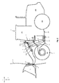
- Figure 1 shows the construction machine 1 in a simplified side view. Elements which are not essential for the invention are omitted.
- the construction machine 1 comprises a front frame portion 30 and a rear frame portion 20.
- a pair of front wheels 301 is mounted to the front frame portion 30 and a pair of rear wheel 201 is mounted to the rear frame portion 20.
- the front frame portion 30 is mounted to the rear frame portion 20 with an articulating steering arrangement 40.
- the articulating steering arrangement 40 is well known to the skilled person and comprises one ore multiple bearings for providing an articulating mount between the front frame portion 30 and the rear frame portion 20 with a pivoting axis being arranged substantially along the vertical axis of the construction machine 1, e.g. perpendicular with respect to the longitudinal direction of the construction machine 1.
- the articulating steering arrangement 40 provides a tilting between the front frame portion 30 and the rear frame portion 20 in order to provide a steering by changing the angle enclosed between the rotation axis of the front wheels 301 and the rotation axis of the rear wheels 201.
- the articulating steering arrangement 40 can be driven by a not illustrated actuator, such as a hydraulic actuator.
- the type and structure of the articulating steering arrangement 40 is not essential to the invention and can be adapted as required.
- the construction machine 1 according to the example shown in Figure 1 comprises an operator's cab 203 which is mounted to the rear frame portion 20. Inside the operator's cab 203, space for the operator is provided and the required operating and control elements which are not illustrated are accessible by the operator.
- the operator's cab 203 comprises not illustrated windows in order to provide visibility of the surrounding field for the operator.
- An engine compartment 202 is provided at the rear frame portion 20 which houses 1 are multiple power sources for providing power required to operate the construction machine 1.
- the power sources can include but are not limited to an internal combustion engine, such as a diesel engine, which can be coupled to further equipment such as hydraulic pumps, generators and the like.
- the power source is used to provide power for driving the front wheels 301 and/or the rear wheels 201 as well as for providing power for actuators besides other elements of the construction machine.
- the front frame portion 30 extends in the forward direction with respect to the rear frame portion 20.
- the front frame portion 30 is located in front of the operator's cap 203 and the engine compartment 202.
- the application of the lifting arrangement according to the present invention is not limited to the construction machine 1 having such an arrangement.
- the front frame portion 30 tilts with respect to the rear frame portion 20, the operator's cab 203 and the engine compartment 202.
- a modified steering arrangement such as a single wheel steering, front wheel steering or rear wheel steering while the articulating steering arrangement is omitted or provided only as option.
- the lifting arrangement according to the present invention is explained in various embodiments, wherein the lifting arrangement is mounted to the front frame portion 30 of the above explained exemplary construction machine 1 embodied as wheel loader.
- the lifting arrangement according to the first embodiment comprises a main arm 3 having a pivot connector 4 at a proximate end and an equipment connector 5 at a distal end thereof.
- the pivot connector 4 is pivotally supported at a main arm support means 6 which includes a main arm support link 6a in the present embodiment.
- the main arm support means is not limited to a link as shown in the drawings. Rather, any support means can be used as long as the pivot connector 4 of the main arm 3 is movable in the required direction as set out below.
- a slide or guide element can be provided which forms the mains arm support means according to the present invention.
- the main arm support link 6a has a first end 12 and a second end 13, the first end being pivotally connected to the pivot connector 4 of the main arm 3 and the second end 13 being pivotally connected to an element of the front frame portion 30.
- the connection between the pivot connector 4 of the main arm 3 and the first end 12 of the main arm support link 6a can be provided as bearing arrangement of a suitable type in order to provide e.g. a sliding rotation of the main arm 3 with respect to the main arm support link 6a.
- the main arm support link 6a is pivotally mounted to the front frame portion 30 at its second end 13.
- a rotating bearing of a suitable type is arranged for providing the pivotable movement of the main arm support link 6a with respect to the front frame portion 30.
- the main arm support means 6 is arranged such that a movement of the main arm support means 6 provides a movement of the pivot connector 4 in a direction which at least includes a component in the front-rear direction of the construction machine 1. For this reason, the main arm support link 6a is directed in an upward direction with a specific inclination from the vertical direction in the situation in Figure 1 and provided with a pivoting mount to the front frame portion 30.
- a main arm actuating element 11 embodied as linear actuator in Figure 1 is provided in the lifting arrangement.
- the main arm actuating element has a second end 11b which is pivotably mounted to the front frame portion 30 and a first end 11a which is pivotably mounted to the main arm 3.
- the main arm actuating element is embodied as linear actuator such as a hydraulic actuator in the present embodiment but not limited thereto.
- An auxiliary actuating element 21 embodied as linear actuator is provided in the lifting arrangement.
- the auxiliary actuating element 21 has a first end 21a and second end 21b, the first end 21a being pivotably mounted to said main arm support link 6a in the embodiment shown in Figure 1 .
- the second end 21b of the auxiliary actuating element 21 is pivotably mounted to said main arm 3. Accordingly, the auxiliary actuating element 21 operates in order to vary the angle of inclination between the main arm support link 6a and the main arm 3. In other words, by extending the auxiliary actuating element 21, the angle enclosed by the main arm support link 6a and the main arm 3 is increased.
- the main arm 3 By actuating the main arm actuating element 11, the main arm 3 is rotated about a pivot center provided at the second bearing portion 13 of said main arm support link 6a. In other words, by extending the main arm actuating element 21, the main arm 3 is rotated together with the main arm support link 6a in the clockwise direction such that a lifting operation is achieved.
- FIG. 31 discloses the elements of the control system used for the lifting arrangement according to the present invention.
- the shown control system is only an example and elements which are not essential for the invention are not shown in this illustration.
- the control system shown in Figure 31 is mounted in the construction machine at a suitable position.
- the basic element of the control system is a control means 60 which includes a CPU for performing control operations and other calculations which are required for operating the control system.
- Information can be obtained from a determining means 50 for determining a lifted related quantity reflecting a position of said equipment connector 5 with respect to the front frame arrangement 30.
- the determining means 50 can include sensors 51, 52, 51A, 52A.
- the sensors can be embodied as linear sensors 51, 52 which provide information on the extension position of the linear actuators used for the main arm actuating element 11 and the auxiliary actuating element 21.
- Such sensors are well known to the skilled person and will be suitably selected from available types.
- rotation sensors can be mounted to those elements of the lifting arrangement which experience a relative rotation between two elements, such as at the connection between the pivot connector 4 of the main arm 3 and the first bearing portion 12 of the main arm support link 6a or at the bearing portion supporting the second bearing porting 13 of the main arm support link 6a on the front frame portion 30.
- the type of sensors can be selected as needed as long as it is possible to provide information on the relative position of the main arm with respect to the main arm support link 6a as well as the relative position of the main arm support link 6a with respect to the front frame portion 30.
- the determining means 50 using the above mentioned sensors transmits electric signals to the control means 60 which are further processed by the CPU as follows.
- the CPU of the control means 60 communicates with a storage means 63 and is capable of obtaining information from the storage means and of transferring information to the storage means 63.
- the storage means 63 includes besides others information in the form of a set of data, such as functions or patterns.
- an input section 61 communicates with the control means 60.
- the input section 61 is capable of transferring signals to the control means 60 which are e.g. triggered by the operator operating the construction machine.
- the input section 61 can further communicate with additional control systems in order to provide an automatic trigger for transferring signals to the control means 60.
- the control means 60 communicates with an output section 63 which is provided for controlling the actuating system of the lifting arrangement, in particular, the main arm actuating element 11 and the auxiliary actuating element 21.
- the output section 63 can be combined with a not illustrated solenoid section controlling pressures and/or flow rates of hydraulic fluid to and from the pressure chambers of the actuators in a known manner. Consequently, the output section 62 can transfer the signals provided from the control means 60 into actuating movements of the main arm actuating element 11 and the auxiliary actuating element 21.
- the above indicated functions or patterns included in the storage means 63 is used for controlling the movement pattern of the equipment connector 5 of the lifting arrangement in the course of a lifting operation.
- the control system provides a relationship between the movement of the main arm actuating element 11 and the movement of the auxiliary actuating element 21.
- the function or pattern included in the storage means 63 includes a relationship between the operating position of the main arm actuating element and the operating position of the auxiliary actuating element 21. The relationship can be continuous.
- the main arm actuating element 11 Upon further performing the lifting operation from the intermediate position shown in Figure 2 , the main arm actuating element 11 is further extended in order to further rotate the main arm 3 in the clockwise direction in the drawing.
- the auxiliary actuating element 21 is again extended in order to increase the angle enclosed between the main arm 3 and the main arm support link 6a. By this, the pivot connector 4 moved in the forward direction with respect to the frame arrangement.
- a movement pattern of the equipment connector 5 can be provided which deviates from a circular path having a constant radius.
- the above explained resulting movement pattern which can be derived from Figures 1-3 , is achieved by using a closed loop control with signals from the sensors as input and signals from the output section 62 as output.
- the determining means 50 using the sensors continuously determines the extension positions of the main arm actuating element 11 and the auxiliary actuating element 21 under the precondition that linear sensors are used.
- the sensor determining the extension position of the main arm actuating element 11 senses a predetermined extension and transmits this as a signal to the control means 60.
- the control means uses this signal and compares the obtained signal continuously with a selected function or pattern present the storage means.
- the function can be provided as a continuous function defining the relationship between the extension position of the main arm actuating element 11 and the extension position of the auxiliary actuating element 21 such that this comparison will result in a unique output of a target extension position of the auxiliary actuating element 21.
- the output section 62 will control the solenoid section in order to set the auxiliary actuating element 21 to the position which corresponds to the target position obtained from the pattern in the storage means.
- Fig. 32 An exemplary function which is used in the control operation of the lifting arrangement according to the invention is illustrated in Fig. 32 .
- the function shown in Fig. 32 is only an example and the design of this function can e.g. be applied to the lifting arrangements shown in Figs. 7-9 .
- the functions will of course be adapted to the specific geometry of lifting arrangements illustrated in the remaining embodiments and modifications. It is noted that the design of the function is specific for the respective construction of lifting arrangements in that a predetermined path, preferably a substantially vertical path can be achieved along which the equipment connector follows upon a movement between the lowered position and the lifted position thereof.
- the pattern or function can be set such that the movement pattern of the equipment connector can be predetermined in various ways.
- the pattern can be set such that the movement path of the equipment connector 5 follows a substantially vertical path or at least remains within a specific range which is aligned to a vertical direction.
- the bucket 15 shown as example in Figure 1 can be moved from the lowered position shown in Figure 1 to the lifted position shown in Figure 3 through the intermediate position shown in Figure 2 .
- the movement of the equipment connector 5 is controlled by the control system along a predetermined movement path which is shown as path P in the drawings.
- the path P has an S-shape but basically follows a vertical path throughout the movement of the equipment connector from the lowered position to the lifted position.
- the path P deviates from a circular path which is achievable with prior art lifting arrangements in which the pivot connector 4 of the main arm 3 is immovably and stationary with respect to a frame portion of the construction machine 1 and the equipment connector 5 is stationary with respect to the main arm 3.
- the movement of the pivot connector 4 of the main arm is achieved by providing the moveable main arm support means 6 and the auxiliary actuating element 21 in addition to the above discussed control system such that the main arm 3 is moved with a specified movement pattern such that a basically vertical movement range of the equipment connector 5 is achievable.
- the lifting capacity of construction machines of this type is crucial for the operational efficiency of the machine.
- the tilting moment exerted by the load to the construction machine 1 must be considered.
- the point of contact of the front wheels 301 must be considered as tilting point T of the construction machine which is indicated in Figures 1-3 at one of the front wheels 301.
- a tilting moment in the counterclockwise direction in Figure 1 is exerted to the construction machine.
- the weight distribution of the construction machine, in particular at the rear side thereof must be appropriately determined.
- the protruding distance of the equipment connector and the load acting on the equipment connector protrudes further in the intermediate position than in the lowered position or the lifted position.
- the protruding distance in the horizontal direction between the tilting point T defined as point of contact of the front wheel 301 on the ground and the equipment connector is decreased, in particular in the intermediate position, compared to the known arrangement in which the equipment connector 5 follows a circular path.
- the load capacity of the construction machine 1 can be increased due to the fact the tilting moment in the intermediate position of the equipment connector to the construction machine is decreased.
- the construction machine can be downsized while maintaining the same load capacity by using the inventive concept discussed above.
- the path P shown in the drawings is only an example in order to illustrate that the path P deviates from a circular path which is achieved by prior art lifting arrangements.
- the shape of the path P can be influenced appropriately, in particular based on the pattern or function stored in the storage means.
- the path P can be considered as vertical path as it deviates from the circular path and is close to a vertical line. It is sufficient in the context of the present invention that the path P remains within a predetermined range of distance between the tilting point T defined by the point of contact of the front wheels 301 with the ground and the vertical distance to the path P.
- a further advantage of the above discussed lifting arrangement shown in Figures 1-3 is that the structure is based on a control system which uses a control means, inputs from sensors and predetermined patterns stored in a storage means.
- the pattern stored in the storage means 63 and used for operating the closed loop control can be appropriately adapted to the needs, the system is flexible and can be operated as vertical lift system or as radial lift arrangement depending on the activated or selected pattern or functions kept in the storage means 63.
- Figures 4-6 show a second embodiment of the present invention.
- the present embodiment differs from the first embodiment in that the auxiliary actuating element 21 is arranged in a different position. While the second end 21b of the auxiliary actuating element 21 is pivotably mounted to the main arm 3 as in the first embodiment, the first end 21a thereof is pivotably attached to an actuation extension 6b mounted to the main arm support link 6a.
- the actuation extension 6b is mounted to the main arm support link 6a on the opposite side to which the main arm support link 6a extends from the second bearing portion thereof. Moreover, the actuation extension 6b is mounted to the main arm support link 6a in a tilted manner, e.g. tilted towards the main arm 3, as can be derived from Figure 4 .
- the second end 21b of the auxiliary actuating element 21 is pivotably attached to the main arm 3 at a position between the pivot connector 4 of the main arm 1 and the location where the first end 11a of the main arm actuating element 11 is attached.
- the remaining arrangement and functions are the same as in the first embodiment.
- the auxiliary actuating element 21 is arranged in a different manner.
- the second end 21b of the auxiliary actuating element 21 is pivotably attached to a bearing attached to the front frame portion 30.
- the first end 21a of the auxiliary actuating element 21 is, as in the first embodiment, pivotably attached to the main arm support link 6a. Consequently, the main arm support link 6a can be moved, e.g. rotated about the second bearing portion 13 thereof by an operation of the auxiliary actuating element 21.
- the remaining arrangement is the same as in the first embodiment.
- the auxiliary actuating element 21 is mounted in a different manner.
- the second end 21b of the auxiliary actuating element 21 is pivotably mounted to a bearing attached to the front frame portion 30.
- the first end 21a of the auxiliary actuating element 21 is pivotably mounted to an actuation extension 6b which is mounted to the main arm support link 6a.
- the actuation extension 6b is mounted to the main arm support link on the opposite side with respect to the second bearing portion 13 of the main arm support link 6a.
- the extension is slightly angled towards the main arm 3. The remaining arrangement is the same as in the first embodiment.
- the auxiliary actuating element 21 is mounted to a bearing portion attached to the front frame portion 30 with its second end 21b.
- the first end 21a thereof is pivotably mounted to the main arm support link 6a.
- the main actuating element is attached with its first end 11a to the main arm 3.
- the second end 11b of the main arm actuating element 11 is attached to an actuation extension 6b which is mounted to the main arm support link 6a on the opposite side thereof with respect to the second bearing portion 13.
- the actuation extension 6b is slightly inclined with respect to the main arm support link 6a towards the main arm 3. The remaining arrangement is the same as in the first embodiment.
- the auxiliary actuating element 21 is mounted to a bearing portion attached to the front frame portion 30 with its second end 21b.
- the first end 21a thereof is pivotably mounted to an extension 6b which is mounted to the main arm support link 6a on the opposite side thereof with respect to the second bearing portion 13.
- the main arm actuating element 11 is mounted with its first end to the main arm and with its second end 11b to a bearing portion attached to the front frame portion 30. The remaining arrangement is the same as in the first embodiment.
- the auxiliary actuating element 21 is mounted with its second end 21b to a bearing portion attached to the front frame portion 30.
- the first end 21a thereof is pivotably mounted to the support link 6a.
- the main arm actuating element 11 is attached to the main arm 3 with its first end 11a, whereas its second end 11b is pivotably attached to the main arm support link 6a.
- the second end 11b of the main arm actuating element 11 is pivotably attached to the main arm support link 6a at a position between the pivot connector 4 and the position at which the first end 21a of the auxiliary actuating element 21 is attached to the main arm support link 6a.
- the first end 11a of the main arm actuating element 11 is attached to the main arm 3 at an extension such that the point of rotation at the first end 11a of the main arm actuating element deviates from a line connecting the equipment connector 5 and the pivot connector 4.
- this extension protrudes to the side on which the main arm actuating element 11 is arranged with respect to the main arm 3. The remaining arrangement is the same as in the first embodiment.
- the main arm actuating element 11 is arranged as in the seventh embodiment.
- the auxiliary actuating element 21 is with its second end 21b mounted to a bearing portion attached to the front frame portion 30.
- the first end 21a of the auxiliary actuating element 21 is pivotably attached to an actuation extension 6b which is arranged on the opposite side of the main arm support link 6a with respect to the second bearing portion 13 thereof.
- the remaining arrangement is the same as in the first embodiment.
- FIG. 25-27 An ninth embodiment is shown in Figures 25-27 . While the arrangement of the main actuating element 11 is the same as in the first embodiment, the present embodiment differs from the previous embodiments in that the pivot connector 4 is arranged stationary with respect to the front frame portion 30.
- an auxiliary actuating element 22 is provided in combination with the main arm 3 as can be derived from Figure 26 . As can be seen, the auxiliary actuating element 22 is formed as linear actuator which is mounted aligned to the extension direction of the main arm 3. One end of the auxiliary actuating element 22, e.g. the end facing backwards, is fixedly mounted to the main arm 3. The other end of the auxiliary actuating element 22 is engaged to a portion carrying the equipment connector 5.
- An extending or retracting operation of the auxiliary actuating element 22 leads to a translatory movement of the equipment connector 5 in a direction which includes at least a component in the front-rear direction with respect to the frame arrangement of the construction machine.
- the main arm 3 can include a slide or guide arrangement in order to provide the translatory movement of the element carrying the equipment connector 5. This slide or guide arrangement is translatory driven by the auxiliary actuating element 22.
- the above discussed control system can be applied to the above ninth embodiment in the same manner in order to achieve a predetermined path along which the equipment connector follows upon a lifting operation from the lower position shown in Figure 25 to a lift position shown in Figure 27 through an intermediate position shown in Figure 26 .
- the advantages of the present embodiment are the same as in the previous embodiments.
- the control system and the structure of the construction machine to which the lifting arrangement according to the present embodiment can be applied are the same as in the previous embodiments.
- the position of the main actuating element 11 is different in that the second end 11b of the main arm actuating element 11 is arranged in a vertical higher position at the front frame portion 30, whereas the first end 11a of the main arm actuating element 11 is pivotably mounted to the main arm 3 at a position which is further remote from the pivot connector 4 in the previous eighth embodiment.
- amendments and revisions of the specific attachment positions are possible throughout the above embodiments depending on the specific requirements in order to provide the desired lifting operation. That is, the above disclosed specific positions are not essential to the invention and any revisions or adaptations can be performed as long as the basic concept of the invention can be achieved which is defined in the claims.
- first ends of the actuating elements such as the first end 11a and the second end 11b of the main arm actuating element 11 as well as the first end 21a and the second end 22b of the auxiliary actuating element 21 can be reversed as long as the actuating elements achieve an operation of the lifting arrangement based on an extension of retracting action thereof.
- arrangement of the ninth embodiment or of the modification thereof can be combined with the arrangements of the remaining embodiments leading to a further improvement of the resulting lifting arrangement.
Landscapes
- Engineering & Computer Science (AREA)
- Mechanical Engineering (AREA)
- Structural Engineering (AREA)
- Civil Engineering (AREA)
- Mining & Mineral Resources (AREA)
- General Engineering & Computer Science (AREA)
- Transportation (AREA)
- Life Sciences & Earth Sciences (AREA)
- Geology (AREA)
- Operation Control Of Excavators (AREA)
- Jib Cranes (AREA)
- Invalid Beds And Related Equipment (AREA)
Abstract
Description
- The present invention relates to a lifting arrangement for a construction machine. In particular, the present invention relates to a lifting arrangement which can be advantageously applied to a wheel loader.
- Construction machines include those which are used for lifting heavy loads such as in mining or similar operations. Mobile construction machines having a lifting arrangement are known such as wheel loaders or the like. For such applications it is crucial to provide a maximum loading and lifting capacity for the lifting arrangement as this is the main factor affecting the operational efficiency of such construction machines. An operation of construction machines using lifting arrangements includes a loading operation of the material to be lifted at a lower level, a lifting operation for lifting the load to a higher level and an unloading operation e.g. for dumping or unloading the lifted load at the higher level.
- In specific applications using a lifting arrangement which is mounted at the front area of mobile construction machines, the lifting capacity is not only limited by the available power driving actuators used for lifting the load. Rather, a weight distribution of such mobile construction machines is a limiting factor restricting the lifting capacity of such lifting arrangements as the mobile construction machine must remain stable in the course of the lifting operation. Consequently, variations of the weight distribution of the mobile construction machines or an increase of the total weight of the machine are considered in order to enhance the lifting capacity of the lifting arrangement. However, such variations in weight distribution or even an increase of the total weight of the mobile construction machine have clearly a negative influence on the drivability and the overall weight of the construction machine. Moreover, drive sources for driving the machine must be designed for such an increased weight of the machine which deteriorates the overall efficiency in view of a specified maximum lifting capacity. The above disadvantages have been accepted previously in order to provide construction machines having the desired lifting capacity.
- It is the object of the present invention, to provide an improved lifting arrangement for a construction machine which enhances the loading and lifting capacity without negatively affecting the overall efficiency of the construction machine.
- The object is solved by a lifting arrangement for a construction machine having the features of the independent claims. Further advantageous developments of the invention are defined in the dependent claims.
- According to a first aspect of the present invention, a lifting arrangement for a construction machine having a frame arrangement with a front frame portion and a rear frame portion is provided, wherein said lifting arrangement is mountable to said frame arrangement. According to the present aspect of the invention, the lifting arrangement comprises the following:
- A main arm which is provided with a pivot connector at a proximate end thereof and an equipment connector at a distal end thereof,
- a main arm support means for pivotably supporting said pivot connector of said main arm,
- wherein said main arm support means is movably mounted on said frame arrangement such that said pivot connector of said main arm is movable in a direction which includes at least a component in the front-rear direction which respect to said frame arrangement,
- a main arm actuating element engaged to said main arm and an auxiliary actuating element engaged to said main arm support means, for moving said equipment connector between a lowered position and a lifted position,
- determining means for determining a lifting related quantity reflecting a position of said equipment connector with respect to said front frame arrangement, and
- control means for controlling an operation of said main arm actuating element and said auxiliary actuating element based on the determined lifting related quantity, such that a part of said equipment connector upon moving said main arm between said lowered position and said lifted position follows a predetermined path, preferably a substantially vertical path.
- According to the above aspect, the lifting arrangement uses a main arm which is pivotably supported in order to transfer a pivoting movement of said main arm into a lifting movement of said equipment connector. In addition, the main arm support means provides a predetermined movability of the pivot connector of said main arm in order to influence the path along which said equipment connector moves in the course of said lifting operation. Due to the fact that said main arm support means is movably mounted to said frame arrangement, i.e. is movable in a direction which includes at least a component in the front-rear direction with respect to said frame arrangement, a predetermined path along which said equipment connector moves can be achieved. This predetermined path can be a path which deviates from a circular path with a radius which is determined by the distance between the pivot connector and the equipment connector.
- As the movement of said main arm support means can be controlled to a predetermined movement pattern in accordance with the lifting operation of said lifting arrangement, a predetermined path can be achieved. Based on the function of the determining means and the control means, the operation of the above mentioned main arm actuating element and auxiliary actuating element can be controlled such that a substantially vertical path is achievable.
- According to an embodiment of the invention, said main arm support means is formed as main arm support link having a first bearing portion a second bearing portion, said first bearing portion being pivotably mounted to said pivot connector of said main arm and said second bearing portion being pivotably mounted to said front frame portion. According to this embodiment, the movability of said main arm support means is achieved with simple means such as the above mentioned support link which is mounted to said front frame portion such that said main arm support means extends in an upward direction. With such a construction, the tilting or pivoting movement of said support link provides movability in a direction which includes at least a component in the front-rear direction with respect to said frame arrangement.
- According to an embodiment of the invention, said main arm actuating element has a first end and a second end, the first end being pivotably mounted to said main arm at a position between said pivot connector and said equipment connector. The use of such an arrangement provides a simple actuating operation of said main arm in order to provide the required pivoting movement of said main arm in order to achieve the lifting operation of said equipment connector.
- According to an embodiment of the invention, said auxiliary actuating element has a first end and a second end, the first end being pivotably mounted to said main arm support means. This arrangement allows a predetermined movement of said main arm support element by operating said auxiliary actuating element. With such an operation, said pivot connector of said main arm is movable in a direction which includes at least a component in the front-rear direction with respect to said frame arrangement.
- According to an embodiment of the invention, said second end of said auxiliary actuating element is pivotably mounted to said main arm. As alternative, said second end of said auxiliary actuating element is pivotably mounted to said front frame portion. Based on the above alternatives, the cooperation of said auxiliary actuating element and said main arm actuating element provides the pivoting movement of said main arm in association with a movement of said main arm support means in order to achieve the predetermined pattern of movement of said equipment connector.
- According to an embodiment of the invention, said second end of said main arm actuating means is pivotably mounted to said front frame portion. As alternative, said second end of said main arm actuating means is pivotably mounted to said main arm support means. With such an arrangement, the cooperation of said main arm actuating element and said auxiliary actuating element allow the predetermined movement pattern of said equipment connector in the course of a lifting operation.
- According to an embodiment of the invention, said support link includes an actuation extension which is mounted to said second bearing portion and extends straight or angled with respect to a longitudinal direction of said support link, said first end of said auxiliary actuating element being pivotably mounted to said actuation extension. With such an arrangement, the construction can be made compact while the required forces from said auxiliary actuating element can be exerted properly to said support link in order to provide the required movement of said support link in the course of a lifting operation.
- According to an embodiment of the invention, said determining means includes a first sensing means for determining a rotational position of said main arm with respect to said main arm support means and a second sensing means for determining the position of said main arm support means with respect to said front frame portion, wherein said first and second sensing means preferably include at least one of an angle sensor and a linear sensor. As the lifting arrangement according to the present invention is based on a control system controlling the operations of the respective actuators, the rotation position of said main arm with respect to said main arm support means and of said main arm support means with respect to said front frame portion are obtained in order to provide a proper control operation. Based on such a proper control operation, the predetermined movement pattern of said equipment connector in the course of a lifting operation is achievable. The sensing means are not limited to those which directly sense rotational positions of the tilting or pivoting components. Rather any sensing means for providing position related information of said main arm and said support means which can be transformed into the required information can be used.
- According to an embodiment of the invention, at least one linear sensor is mounted to said main arm actuating element and/or to said auxiliary actuating element for determining a respective extension position thereof. As the tilting or rotation action of the respective tilting or rotating elements of the lifting arrangement is associated with the extension length of the respective actuators in case that linear actuators are used, linear sensors are useful for obtaining the respective information. In particular, the linear sensors can be preferably integrated to said linear actuators such that the arrangement can be provided which is compact and simple in construction.
- According to an embodiment of the invention, said control means is equipped with a storage means storing a pattern defining a unique relationship between an actuating position of said main arm actuating element and an actuating position of said support means actuating element, wherein the control performed by said control means is based on said pattern. The pattern is not limited to a specific pattern. Rather, the pattern is selected such that the cooperation of movements of the respective actuating elements is predetermined such that the desired path along which the equipment connector follows in the course of a lifting operation can be achieved. Preferably, the pattern used by the control means is such that the path along which the equipment connector moves, is substantially a vertical path.
- It is noted that the substantially vertical path is not limited to a strict vertical line with respect to the horizontal direction or the longitudinal direction of the construction machine, but rather a specific range is allowed in which said equipment connector moves in the course of a lifting operation, wherein said range is aligned to the vertical direction and the width of the range extends in the longitudinal direction of said construction machine.
- According to the invention, it is possible to achieve a path along which the equipment connector moves upon a lifting operation which deviates from a circular path with a radius which is determined by the distance between the pivot connector and the equipment connector of said main arm. The main purpose of the lifting arrangement according to the invention is to provide a movement path of said equipment connector which provides a decreased protruding distance in the intermediate position of said equipment connector which is positioned between the lowered position and the lifted position of said equipment connector. Based on this concept, the tilting moment exerted by the load acting on said equipment connector can be reduced when compared to the tilting moment acting on a construction machine having a main arm which provides a movement path for the equipment connector along a circular path with a radius which is defined by the distance between the pivot connector and the equipment connector.
- It is noted that the pattern stored in said storage means can be replaced or changed automatically or by manipulation by the operator in order to provide a variety of movement patterns of said equipment connector in the course of a lifting operation.
- According to an embodiment of the invention, said relationship is such that a movement of said equipment connector follows a predetermined path upon lifting said equipment connector between said lowered position and said lifted position.
- According to an embodiment of the invention, at least one of a bucket and a lifting fork for lifting heavy loads is mounted, preferably tiltably mounted to said equipment connector. A bucket can be used to load, lift and unload bulky matters such as in mining or the like. The lifting fork for lifting heavy loads can be used to lift large single piece loads. Both can be understood as equipment to be mounted at the equipment connector. Preferably, the equipment mountable to said equipment connector is arranged with the option of tilting the equipment. The above mentioned bucket or lifting fork are not limiting the invention. Rather, any equipment can be mounted to the equipment connector with or without tilting option as long as a lifting operation is involved.
- According to a second aspect of the present invention, a wheel load is provided which has an articulating frame arrangement consisting of a front frame portion and a rear frame portion which are articulatingly interconnected for providing an articulating steering, comprising a lifting arrangement according to one of the above mentioned embodiments.
- As discussed above, the lifting arrangement can be constructed as compact structure while the advantage of providing the specified path of the equipment connector can be achieved. When applied to a wheel loader, such a compact arrangement is particularly advantageous due to the fact that an articulating steering is provided between a front frame portion and a rear frame portion.
- Accordingly, it is a specific advantage of this aspect of the present invention, that elements forming said lifting arrangement are supported by said front frame portion or said articulating frame arrangement and are articulated together with said front frame portion with respect to said rear frame portion upon steering actions.
- In this case, the equipment connected to the equipment connector is preferably provided in front of the front frame portion, wherein the elements of said lifting arrangement are supported by said front frame portion. As the front frame portion in an articulating frame arrangement substantially follows the direction of the front wheels, the operation of the wheel loader following this concept can be operated without any surprising changes in the behavior compared to a standard wheel loader. However, it is also possible to provide a part of the elements forming the lifting arrangement at the rear frame portion. Also, it is possible to provide all elements of the lifting arrangement at the rear frame portion depending on the specific needs.
- According to a third aspect of the present invention, a lifting arrangement for a construction machine is provided, the construction machine having a frame arrangement with a front frame portion and a rear frame portion, said lifting arrangement being mountable to said frame arrangement. According to the present aspect of the invention, the lifting arrangement comprises the following:
- a main arm which is provided with a pivot connector at a proximate end thereof and an equipment connector at a distal end thereof,
- a main arm support means for pivotably supporting said pivot connector of said main arm,
- a main arm actuating element engaged to said main arm for moving said equipment connector between a lowered position and a lifted position, and an auxiliary actuating element which is mounted to said main arm and engaged to said equipment connector for moving said equipment connector in a direction which includes at least a component in the front-rear direction with respect to said frame arrangement,
- determining means for determining a lifting related quantity reflecting a position of said equipment connector with respect to said front frame arrangement, and
- control means for controlling an operation of said main arm actuating element and said auxiliary actuating element based on the determined lifting related quantity, such that a path of said equipment connector upon moving said main arm between said lowered position and said lifted position follows a predetermined path, preferably a substantially vertical path.
- According to the above aspect, the tilting movement of said main arm provides a lifting operation wherein the position of the equipment connector with respect to said main arm can be controlled by operating said auxiliary actuating element. In this context, the auxiliary actuating element is mounted to said main arm and arranged for changing the position of the equipment connector with respect to said main arm. Preferably, said auxiliary actuating element is formed as linear actuator which is substantially aligned to the longitudinal direction of said main arm. Consequently, the distance between said pivot connector of said main arm and said equipment connector can be controlled by actuating said auxiliary actuating element. As consequence, a cooperating control of said auxiliary actuating element and said main arm actuating element in association with said control means provides a path along which said equipment connector moves which deviates from a circular path having a constant radius. The use of a specific pattern for controlling said auxiliary actuating element and said main arm actuating element in the course of the movement of the equipment connector between a lowered positon and a lifted position allows that a predetermined path is achieved. In particular, a specified pattern can be used which provides a path along which the equipment connector follows which is preferably a substantially vertical path as discussed above with respect to the previous aspects of the invention.
- It is noted that the above mentioned embodiments can be applied to the third aspect of the invention and provide the same or similar effects and advantages as discussed above. In particular, the application of the third aspect of the invention to a wheel loader having an articulating frame arrangement as defined in the second aspect is also covered by the invention.
- Nevertheless, it is explicitly noted that the application of the lifting arrangement is not limited to wheel loaders having an articulating frame arrangement. Due to the compact structure of the inventive lifting arrangement with respect to the above aspects and embodiments, the application to any construction machine provides the same advantage as discussed above.
- The invention is explained based on the enclosed drawings showing an exemplary construction machine equipped with a lifting arrangement according to various embodiments and modifications. It is noted that the following drawings should not be considered as limiting the invention set out in the claims. Moreover, the illustrated construction machine is merely an example and the lifting arrangement according to the invention is applicable to various types of construction machines.
- Figure 1
- illustrates a construction machine equipped with a lifting arrangement according to a first embodiment in a lowered position;
- Figure 2
- illustrates a construction machine equipped with the lifting arrangement according to the first embodiment in an intermediate position;
- Figure 3
- illustrates a construction machine equipped with the lifting arrangement according to the first embodiment in a lifted position;
- Figure 4
- illustrates a construction machine equipped with a lifting arrangement according to a second embodiment in a lowered position;
- Figure 5
- illustrates a construction machine equipped with the lifting arrangement according to the second embodiment in an intermediate position;
- Figure 6
- illustrates a construction machine equipped with the lifting arrangement according to the second embodiment in a lifted position;
- Figure 7
- illustrates a construction machine equipped with a lifting arrangement according to a third embodiment in a lowered position;
- Figure 8
- illustrates a construction machine equipped with the lifting arrangement according to the third embodiment in an intermediate position;
- Figure 9
- illustrates a construction machine equipped with the lifting arrangement according to the third embodiment in a lifted position;
- Figure 10
- illustrates a construction machine equipped with a lifting arrangement according to a fourth embodiment in a lowered position;
- Figure 11
- illustrates a construction machine equipped with the lifting arrangement according to the fourth embodiment in an intermediate position;
- Figure 12
- illustrates a construction machine equipped with the lifting arrangement according to the fourth embodiment in a lifted position;
- Figure 13
- illustrates a construction machine equipped with a lifting arrangement according to a fifth embodiment in a lowered position;
- Figure 14
- illustrates a construction machine equipped with the lifting arrangement according to the fifth embodiment in an intermediate position;
- Figure 15
- illustrates a construction machine equipped with the lifting arrangement according to the fifth embodiment in a lifted position;
- Figure 16
- illustrates a construction machine equipped with a lifting arrangement according to a sixth embodiment in a lowered position;
- Figure 17
- illustrates a construction machine equipped with the lifting arrangement according to the sixth embodiment in an intermediate position;
- Figure 18
- illustrates a construction machine equipped with the lifting arrangement according to the sixth embodiment in a lifted position;
- Figure 19
- illustrates a construction machine equipped with a lifting arrangement according to a seventh embodiment in a lowered position;
- Figure 20
- illustrates a construction machine equipped with the lifting arrangement according to the seventh embodiment in an intermediate position;
- Figure 21
- illustrates a construction machine equipped with the lifting arrangement according to the seventh embodiment in a lifted position;
- Figure 22
- illustrates a construction machine equipped with a lifting arrangement according to an eighth embodiment in a lowered position;
- Figure 23
- illustrates a construction machine equipped with the lifting arrangement according to the eighth embodiment in an intermediate position;
- Figure 24
- illustrates a construction machine equipped with the lifting arrangement according to the eighth embodiment in a lifted position;
- Figure 25
- illustrates a construction machine equipped with a lifting arrangement according to a ninth embodiment in a lowered position;
- Figure 26
- illustrates a construction machine equipped with the lifting arrangement according to the ninth embodiment in an intermediate position;
- Figure 27
- illustrates a construction machine equipped with the lifting arrangement according to the ninth embodiment in a lifted position;
- Figures 28 to 30
- illustrate a construction machine equipped with a lifting arrangement according to a modification of the ninth embodiment;
- Figure 31
- illustrates components of the control system applied to the lifting arrangement according to the embodiments;
- Figure 32
- illustrates an exemplary function which is used in the control of the lifting arrangement according to the invention.
- In the following, embodiments and modifications of the present invention are explained in detail based on the drawings. It is noted that the below discussed embodiments can be combined with each other and the invention is not specifically restricted to the structure and arrangement of the specific embodiments and modifications discussed below.
- The present invention relates to a lifting arrangement which is applicable to construction machines in general. In the following embodiments, the lifting arrangement is illustrated and explained as structure of a construction machine which is embodied as wheel loader. However, the specific application of the lifting arrangement according to the present invention is not limited to the application to a wheel loader. Rather, the lifting arrangement according to the present invention can be applied to a drivable construction machine of any type such as loaders having wheels or crawler track chains or even a combination of both. Moreover, the steering type is not limited to the below discussed optional articulating steering arrangement. Rather, the lifting arrangement is applicable to construction machines having any type of steering arrangements such as articulating steering arrangements, skid steering arrangements or any other type.
- The construction machine to which the lifting arrangement according to the present invention is applicable is briefly explained based on the illustration of
Figure 1. Figure 1 shows theconstruction machine 1 in a simplified side view. Elements which are not essential for the invention are omitted. - The
construction machine 1 comprises afront frame portion 30 and arear frame portion 20. In the example according toFigure 1 , a pair offront wheels 301 is mounted to thefront frame portion 30 and a pair ofrear wheel 201 is mounted to therear frame portion 20. Thefront frame portion 30 is mounted to therear frame portion 20 with an articulatingsteering arrangement 40. The articulatingsteering arrangement 40 is well known to the skilled person and comprises one ore multiple bearings for providing an articulating mount between thefront frame portion 30 and therear frame portion 20 with a pivoting axis being arranged substantially along the vertical axis of theconstruction machine 1, e.g. perpendicular with respect to the longitudinal direction of theconstruction machine 1. The articulatingsteering arrangement 40 provides a tilting between thefront frame portion 30 and therear frame portion 20 in order to provide a steering by changing the angle enclosed between the rotation axis of thefront wheels 301 and the rotation axis of therear wheels 201. The articulatingsteering arrangement 40 can be driven by a not illustrated actuator, such as a hydraulic actuator. The type and structure of the articulatingsteering arrangement 40 is not essential to the invention and can be adapted as required. - The
construction machine 1 according to the example shown inFigure 1 comprises an operator'scab 203 which is mounted to therear frame portion 20. Inside the operator'scab 203, space for the operator is provided and the required operating and control elements which are not illustrated are accessible by the operator. The operator'scab 203 comprises not illustrated windows in order to provide visibility of the surrounding field for the operator. - An
engine compartment 202 is provided at therear frame portion 20 which houses 1 are multiple power sources for providing power required to operate theconstruction machine 1. The power sources can include but are not limited to an internal combustion engine, such as a diesel engine, which can be coupled to further equipment such as hydraulic pumps, generators and the like. The power source is used to provide power for driving thefront wheels 301 and/or therear wheels 201 as well as for providing power for actuators besides other elements of the construction machine. - The
front frame portion 30 extends in the forward direction with respect to therear frame portion 20. In the present example, thefront frame portion 30 is located in front of the operator'scap 203 and theengine compartment 202. However, the application of the lifting arrangement according to the present invention is not limited to theconstruction machine 1 having such an arrangement. - Upon a steering operation, the
front frame portion 30 tilts with respect to therear frame portion 20, the operator'scab 203 and theengine compartment 202. However, it is also possible to provide a modified steering arrangement such as a single wheel steering, front wheel steering or rear wheel steering while the articulating steering arrangement is omitted or provided only as option. - In the following, the lifting arrangement according to the present invention is explained in various embodiments, wherein the lifting arrangement is mounted to the
front frame portion 30 of the above explainedexemplary construction machine 1 embodied as wheel loader. - The lifting arrangement according to the first embodiment comprises a
main arm 3 having apivot connector 4 at a proximate end and anequipment connector 5 at a distal end thereof. Thepivot connector 4 is pivotally supported at a main arm support means 6 which includes a mainarm support link 6a in the present embodiment. However, the main arm support means is not limited to a link as shown in the drawings. Rather, any support means can be used as long as thepivot connector 4 of themain arm 3 is movable in the required direction as set out below. For example, a slide or guide element can be provided which forms the mains arm support means according to the present invention. - The main
arm support link 6a has afirst end 12 and asecond end 13, the first end being pivotally connected to thepivot connector 4 of themain arm 3 and thesecond end 13 being pivotally connected to an element of thefront frame portion 30. The connection between thepivot connector 4 of themain arm 3 and thefirst end 12 of the mainarm support link 6a can be provided as bearing arrangement of a suitable type in order to provide e.g. a sliding rotation of themain arm 3 with respect to the mainarm support link 6a. - The main
arm support link 6a is pivotally mounted to thefront frame portion 30 at itssecond end 13. In order to provide such a pivotable mount of the mainarm support link 6a to thefront frame portion 30, a rotating bearing of a suitable type is arranged for providing the pivotable movement of the mainarm support link 6a with respect to thefront frame portion 30. - The main arm support means 6 according to the invention is arranged such that a movement of the main arm support means 6 provides a movement of the
pivot connector 4 in a direction which at least includes a component in the front-rear direction of theconstruction machine 1. For this reason, the mainarm support link 6a is directed in an upward direction with a specific inclination from the vertical direction in the situation inFigure 1 and provided with a pivoting mount to thefront frame portion 30. - A main
arm actuating element 11 embodied as linear actuator inFigure 1 is provided in the lifting arrangement. The main arm actuating element has asecond end 11b which is pivotably mounted to thefront frame portion 30 and afirst end 11a which is pivotably mounted to themain arm 3. The main arm actuating element is embodied as linear actuator such as a hydraulic actuator in the present embodiment but not limited thereto. - An
auxiliary actuating element 21 embodied as linear actuator is provided in the lifting arrangement. Theauxiliary actuating element 21 has afirst end 21a andsecond end 21b, thefirst end 21a being pivotably mounted to said mainarm support link 6a in the embodiment shown inFigure 1 . Thesecond end 21b of theauxiliary actuating element 21 is pivotably mounted to saidmain arm 3. Accordingly, theauxiliary actuating element 21 operates in order to vary the angle of inclination between the mainarm support link 6a and themain arm 3. In other words, by extending theauxiliary actuating element 21, the angle enclosed by the mainarm support link 6a and themain arm 3 is increased. - By actuating the main
arm actuating element 11, themain arm 3 is rotated about a pivot center provided at thesecond bearing portion 13 of said mainarm support link 6a. In other words, by extending the mainarm actuating element 21, themain arm 3 is rotated together with the mainarm support link 6a in the clockwise direction such that a lifting operation is achieved. - Reference is made to
Figure 31 which discloses the elements of the control system used for the lifting arrangement according to the present invention. The shown control system is only an example and elements which are not essential for the invention are not shown in this illustration. The control system shown inFigure 31 is mounted in the construction machine at a suitable position. The basic element of the control system is a control means 60 which includes a CPU for performing control operations and other calculations which are required for operating the control system. Information can be obtained from a determining means 50 for determining a lifted related quantity reflecting a position of saidequipment connector 5 with respect to thefront frame arrangement 30. The determining means 50 can include sensors 51, 52, 51A, 52A. The sensors can be embodied as linear sensors 51, 52 which provide information on the extension position of the linear actuators used for the mainarm actuating element 11 and theauxiliary actuating element 21. Such sensors are well known to the skilled person and will be suitably selected from available types. As alternative, rotation sensors can be mounted to those elements of the lifting arrangement which experience a relative rotation between two elements, such as at the connection between thepivot connector 4 of themain arm 3 and thefirst bearing portion 12 of the mainarm support link 6a or at the bearing portion supporting the second bearing porting 13 of the mainarm support link 6a on thefront frame portion 30. The type of sensors can be selected as needed as long as it is possible to provide information on the relative position of the main arm with respect to the mainarm support link 6a as well as the relative position of the mainarm support link 6a with respect to thefront frame portion 30. The determining means 50 using the above mentioned sensors transmits electric signals to the control means 60 which are further processed by the CPU as follows. - The CPU of the control means 60 communicates with a storage means 63 and is capable of obtaining information from the storage means and of transferring information to the storage means 63. The storage means 63 includes besides others information in the form of a set of data, such as functions or patterns.
- Furthermore, an
input section 61 communicates with the control means 60. Theinput section 61 is capable of transferring signals to the control means 60 which are e.g. triggered by the operator operating the construction machine. As alternative or in addition, theinput section 61 can further communicate with additional control systems in order to provide an automatic trigger for transferring signals to the control means 60. - The control means 60 communicates with an
output section 63 which is provided for controlling the actuating system of the lifting arrangement, in particular, the mainarm actuating element 11 and theauxiliary actuating element 21. Theoutput section 63 can be combined with a not illustrated solenoid section controlling pressures and/or flow rates of hydraulic fluid to and from the pressure chambers of the actuators in a known manner. Consequently, theoutput section 62 can transfer the signals provided from the control means 60 into actuating movements of the mainarm actuating element 11 and theauxiliary actuating element 21. - The above indicated functions or patterns included in the storage means 63 is used for controlling the movement pattern of the
equipment connector 5 of the lifting arrangement in the course of a lifting operation. According to the present invention, the control system provides a relationship between the movement of the mainarm actuating element 11 and the movement of theauxiliary actuating element 21. In other words, the function or pattern included in the storage means 63 includes a relationship between the operating position of the main arm actuating element and the operating position of theauxiliary actuating element 21. The relationship can be continuous. - The operation of the control based lifting arrangement is explained in the following. Starting out from the situation in
Figure 1 , the operator manipulates a not illustrated operating element which is associated with theinput section 61 in order to initiate a lifting operation for lifting theequipment connector 5 from the lowered position shown inFigure 1 to a lifted position shown inFigure 3 through an intermediate position shown inFigure 2 . With the lifting arrangement shown inFigure 1 , the mainarm actuating element 11 is extended in order to rotate themain arm 3 together with the mainarm support link 6a in the clockwise direction in the drawing. In the course of the operation of the mainarm actuating element 11, theauxiliary actuating element 21 is retracted as can be derived from a comparison ofFigure 1 withFigure 2 . Based on this retraction of theauxiliary actuating element 21, the angle enclosed between themain arm 3 and the mainarm support link 6a is decreased and thepivot connector 4 is withdrawn in the rearward direction with respect to the frame arrangement. - Upon further performing the lifting operation from the intermediate position shown in
Figure 2 , the mainarm actuating element 11 is further extended in order to further rotate themain arm 3 in the clockwise direction in the drawing. In the course of the lifting operation between the intermediate position shown inFigure 2 towards the lifted position shown inFigure 3 , theauxiliary actuating element 21 is again extended in order to increase the angle enclosed between themain arm 3 and the mainarm support link 6a. By this, thepivot connector 4 moved in the forward direction with respect to the frame arrangement. - Based on the above cooperation of the main
arm actuating element 11 and theauxiliary actuating element 21 in combination with the construction using the mainarm support link 6a, a movement pattern of theequipment connector 5 can be provided which deviates from a circular path having a constant radius. - The above explained resulting movement pattern which can be derived from
Figures 1-3 , is achieved by using a closed loop control with signals from the sensors as input and signals from theoutput section 62 as output. Starting again out from the situation inFigure 1 , the determining means 50 using the sensors continuously determines the extension positions of the mainarm actuating element 11 and theauxiliary actuating element 21 under the precondition that linear sensors are used. By initiating the lifting operation, the sensor determining the extension position of the mainarm actuating element 11 senses a predetermined extension and transmits this as a signal to the control means 60. The control means uses this signal and compares the obtained signal continuously with a selected function or pattern present the storage means. The function can be provided as a continuous function defining the relationship between the extension position of the mainarm actuating element 11 and the extension position of theauxiliary actuating element 21 such that this comparison will result in a unique output of a target extension position of theauxiliary actuating element 21. Theoutput section 62 will control the solenoid section in order to set theauxiliary actuating element 21 to the position which corresponds to the target position obtained from the pattern in the storage means. - An exemplary function which is used in the control operation of the lifting arrangement according to the invention is illustrated in
Fig. 32 . The function shown inFig. 32 is only an example and the design of this function can e.g. be applied to the lifting arrangements shown inFigs. 7-9 . The functions will of course be adapted to the specific geometry of lifting arrangements illustrated in the remaining embodiments and modifications. It is noted that the design of the function is specific for the respective construction of lifting arrangements in that a predetermined path, preferably a substantially vertical path can be achieved along which the equipment connector follows upon a movement between the lowered position and the lifted position thereof. - The above mentioned closed loop control is continuously performed by the control system such that there is always a unique relationship between the extension position of the main
arm actuating element 11 and the extension position of theauxiliary actuation element 21. According to the present invention, as stated above, the pattern or function can be set such that the movement pattern of the equipment connector can be predetermined in various ways. According to the most preferable solution according to the present invention, the pattern can be set such that the movement path of theequipment connector 5 follows a substantially vertical path or at least remains within a specific range which is aligned to a vertical direction. - Based on the above operation, the
bucket 15 shown as example inFigure 1 can be moved from the lowered position shown inFigure 1 to the lifted position shown inFigure 3 through the intermediate position shown inFigure 2 . Based on the control system and arrangement, the movement of theequipment connector 5 is controlled by the control system along a predetermined movement path which is shown as path P in the drawings. In the present illustration, the path P has an S-shape but basically follows a vertical path throughout the movement of the equipment connector from the lowered position to the lifted position. In particular, the path P deviates from a circular path which is achievable with prior art lifting arrangements in which thepivot connector 4 of themain arm 3 is immovably and stationary with respect to a frame portion of theconstruction machine 1 and theequipment connector 5 is stationary with respect to themain arm 3. According to the present invention, the movement of thepivot connector 4 of the main arm is achieved by providing the moveable main arm support means 6 and theauxiliary actuating element 21 in addition to the above discussed control system such that themain arm 3 is moved with a specified movement pattern such that a basically vertical movement range of theequipment connector 5 is achievable. - In the following, the advantages of the present invention are explained based on the above embodiment. The lifting capacity of construction machines of this type is crucial for the operational efficiency of the machine. In case the construction machine is supposed to be operated for lifting high loads from the lowered position of the bucket to the lifted position of the bucket, the tilting moment exerted by the load to the
construction machine 1 must be considered. In this concept, the point of contact of thefront wheels 301 must be considered as tilting point T of the construction machine which is indicated inFigures 1-3 at one of thefront wheels 301. As the bucket protrudes from the tilting point T in the forward direction, a tilting moment in the counterclockwise direction inFigure 1 is exerted to the construction machine. As countermeasure, the weight distribution of the construction machine, in particular at the rear side thereof, must be appropriately determined. - Considering a prior art lifting arrangement, upon lifting a load based on a main arm having an equipment connector which follows a circular path upon a movement between a lowered position and the lifted position, the protruding distance of the equipment connector and the load acting on the equipment connector protrudes further in the intermediate position than in the lowered position or the lifted position. According to the present invention, the protruding distance in the horizontal direction between the tilting point T defined as point of contact of the
front wheel 301 on the ground and the equipment connector is decreased, in particular in the intermediate position, compared to the known arrangement in which theequipment connector 5 follows a circular path. - Based on the inventive lifting arrangement, the load capacity of the
construction machine 1 can be increased due to the fact the tilting moment in the intermediate position of the equipment connector to the construction machine is decreased. On the other hand the construction machine can be downsized while maintaining the same load capacity by using the inventive concept discussed above. The path P shown in the drawings is only an example in order to illustrate that the path P deviates from a circular path which is achieved by prior art lifting arrangements. Depending on the detailed setting of the control system and the mechanical arrangement, e.g. the setup of distances and length of the links, the shape of the path P can be influenced appropriately, in particular based on the pattern or function stored in the storage means. In the context of the present invention, the path P can be considered as vertical path as it deviates from the circular path and is close to a vertical line. It is sufficient in the context of the present invention that the path P remains within a predetermined range of distance between the tilting point T defined by the point of contact of thefront wheels 301 with the ground and the vertical distance to the path P. - A further advantage of the above discussed lifting arrangement shown in
Figures 1-3 is that the structure is based on a control system which uses a control means, inputs from sensors and predetermined patterns stored in a storage means. As the pattern stored in the storage means 63 and used for operating the closed loop control can be appropriately adapted to the needs, the system is flexible and can be operated as vertical lift system or as radial lift arrangement depending on the activated or selected pattern or functions kept in the storage means 63. In other words, it is possible to provide a plurality of patterns or functions in the storage means 63 which allow different movement patterns of the equipment connector upon a lifting movement and selecting one of the patterns or functions which is activated and selected in the current control mode. - In addition, due to the specific arrangement using the actuators and the main arm support means 6, a very compact arrangement is achievable which does not require the provision of elements of the lifting arrangement at the rear section of the construction machine. As such, this simple lifting arrangement is well applicable to wheel loaders using an articulating steering system which provide only a limited space at the front frame portion for mounting the lifting arrangements.
- In the following, further embodiments of the present invention are explained based on the drawings. It is noted the variations of the following further embodiments can be combined with each other as long as the basic concept set out in the claims is achieved. Moreover, the control system explained above for the first embodiment is applicable to each of the following embodiments in the same way. Therefore, the discussion of the control function as well as the advantages thereof is omitted.
-
Figures 4-6 show a second embodiment of the present invention. The present embodiment differs from the first embodiment in that theauxiliary actuating element 21 is arranged in a different position. While thesecond end 21b of theauxiliary actuating element 21 is pivotably mounted to themain arm 3 as in the first embodiment, thefirst end 21a thereof is pivotably attached to anactuation extension 6b mounted to the mainarm support link 6a. Theactuation extension 6b is mounted to the mainarm support link 6a on the opposite side to which the mainarm support link 6a extends from the second bearing portion thereof. Moreover, theactuation extension 6b is mounted to the mainarm support link 6a in a tilted manner, e.g. tilted towards themain arm 3, as can be derived fromFigure 4 . In addition, thesecond end 21b of theauxiliary actuating element 21 is pivotably attached to themain arm 3 at a position between thepivot connector 4 of themain arm 1 and the location where thefirst end 11a of the mainarm actuating element 11 is attached. The remaining arrangement and functions are the same as in the first embodiment. - In the third embodiment shown in
Figures 7-9 , theauxiliary actuating element 21 is arranged in a different manner. As can be derived best fromFigure 8 , thesecond end 21b of theauxiliary actuating element 21 is pivotably attached to a bearing attached to thefront frame portion 30. Thefirst end 21a of theauxiliary actuating element 21 is, as in the first embodiment, pivotably attached to the mainarm support link 6a. Consequently, the mainarm support link 6a can be moved, e.g. rotated about thesecond bearing portion 13 thereof by an operation of theauxiliary actuating element 21. The remaining arrangement is the same as in the first embodiment. - In the fourth embodiment shown in
Figures 10-12 , theauxiliary actuating element 21 is mounted in a different manner. As in the third embodiment, thesecond end 21b of theauxiliary actuating element 21 is pivotably mounted to a bearing attached to thefront frame portion 30. However, thefirst end 21a of theauxiliary actuating element 21 is pivotably mounted to anactuation extension 6b which is mounted to the mainarm support link 6a. In the present embodiment, theactuation extension 6b is mounted to the main arm support link on the opposite side with respect to thesecond bearing portion 13 of the mainarm support link 6a. As can be derived from the drawings, the extension is slightly angled towards themain arm 3. The remaining arrangement is the same as in the first embodiment. - In the fifth embodiment shown in
Figures 13-15 , theauxiliary actuating element 21 is mounted to a bearing portion attached to thefront frame portion 30 with itssecond end 21b. Thefirst end 21a thereof is pivotably mounted to the mainarm support link 6a. The main actuating element is attached with itsfirst end 11a to themain arm 3. However, thesecond end 11b of the mainarm actuating element 11 is attached to anactuation extension 6b which is mounted to the mainarm support link 6a on the opposite side thereof with respect to thesecond bearing portion 13. As can be seen from the drawings, theactuation extension 6b is slightly inclined with respect to the mainarm support link 6a towards themain arm 3. The remaining arrangement is the same as in the first embodiment. - In the sixth embodiment shown in
Figures 16-18 , theauxiliary actuating element 21 is mounted to a bearing portion attached to thefront frame portion 30 with itssecond end 21b. Thefirst end 21a thereof is pivotably mounted to anextension 6b which is mounted to the mainarm support link 6a on the opposite side thereof with respect to thesecond bearing portion 13. The mainarm actuating element 11 is mounted with its first end to the main arm and with itssecond end 11b to a bearing portion attached to thefront frame portion 30. The remaining arrangement is the same as in the first embodiment. - In the seventh embodiment shown in
Figures 19-21 theauxiliary actuating element 21 is mounted with itssecond end 21b to a bearing portion attached to thefront frame portion 30. Thefirst end 21a thereof is pivotably mounted to thesupport link 6a. The mainarm actuating element 11 is attached to themain arm 3 with itsfirst end 11a, whereas itssecond end 11b is pivotably attached to the mainarm support link 6a. In particular, thesecond end 11b of the mainarm actuating element 11 is pivotably attached to the mainarm support link 6a at a position between thepivot connector 4 and the position at which thefirst end 21a of theauxiliary actuating element 21 is attached to the mainarm support link 6a. Moreover, as can be derived fromFigure 21 , thefirst end 11a of the mainarm actuating element 11 is attached to themain arm 3 at an extension such that the point of rotation at thefirst end 11a of the main arm actuating element deviates from a line connecting theequipment connector 5 and thepivot connector 4. In particular, this extension protrudes to the side on which the mainarm actuating element 11 is arranged with respect to themain arm 3. The remaining arrangement is the same as in the first embodiment. - In an eighth embodiment shown in
Figures 22-24 , the mainarm actuating element 11 is arranged as in the seventh embodiment. Theauxiliary actuating element 21 is with itssecond end 21b mounted to a bearing portion attached to thefront frame portion 30. Thefirst end 21a of theauxiliary actuating element 21 is pivotably attached to anactuation extension 6b which is arranged on the opposite side of the mainarm support link 6a with respect to thesecond bearing portion 13 thereof. The remaining arrangement is the same as in the first embodiment. - An ninth embodiment is shown in
Figures 25-27 . While the arrangement of themain actuating element 11 is the same as in the first embodiment, the present embodiment differs from the previous embodiments in that thepivot connector 4 is arranged stationary with respect to thefront frame portion 30. In addition, anauxiliary actuating element 22 is provided in combination with themain arm 3 as can be derived fromFigure 26 . As can be seen, theauxiliary actuating element 22 is formed as linear actuator which is mounted aligned to the extension direction of themain arm 3. One end of theauxiliary actuating element 22, e.g. the end facing backwards, is fixedly mounted to themain arm 3. The other end of theauxiliary actuating element 22 is engaged to a portion carrying theequipment connector 5. An extending or retracting operation of theauxiliary actuating element 22 according to the present embodiment leads to a translatory movement of theequipment connector 5 in a direction which includes at least a component in the front-rear direction with respect to the frame arrangement of the construction machine. Themain arm 3 can include a slide or guide arrangement in order to provide the translatory movement of the element carrying theequipment connector 5. This slide or guide arrangement is translatory driven by theauxiliary actuating element 22. - The above discussed control system can be applied to the above ninth embodiment in the same manner in order to achieve a predetermined path along which the equipment connector follows upon a lifting operation from the lower position shown in
Figure 25 to a lift position shown inFigure 27 through an intermediate position shown inFigure 26 . The advantages of the present embodiment are the same as in the previous embodiments. In particular, it is possible to provide a movement pattern of theequipment connector 5 along a substantially vertical path or within a predetermined vertical range in order to reduce the tilting moment exerted by the load to the construction machine upon a lifting operation, in particular, in the intermediate lifting position shown inFigure 26 . The control system and the structure of the construction machine to which the lifting arrangement according to the present embodiment can be applied are the same as in the previous embodiments. - In a modification of the ninth embodiment shown in
Figures 28-30 , the position of themain actuating element 11 is different in that thesecond end 11b of the mainarm actuating element 11 is arranged in a vertical higher position at thefront frame portion 30, whereas thefirst end 11a of the mainarm actuating element 11 is pivotably mounted to themain arm 3 at a position which is further remote from thepivot connector 4 in the previous eighth embodiment. It is noted that such amendments and revisions of the specific attachment positions are possible throughout the above embodiments depending on the specific requirements in order to provide the desired lifting operation. That is, the above disclosed specific positions are not essential to the invention and any revisions or adaptations can be performed as long as the basic concept of the invention can be achieved which is defined in the claims. - It is noted that the first ends of the actuating elements, such as the
first end 11a and thesecond end 11b of the mainarm actuating element 11 as well as thefirst end 21a and the second end 22b of theauxiliary actuating element 21 can be reversed as long as the actuating elements achieve an operation of the lifting arrangement based on an extension of retracting action thereof. Also, the arrangement of the ninth embodiment or of the modification thereof can be combined with the arrangements of the remaining embodiments leading to a further improvement of the resulting lifting arrangement.REFERENCE SIGNS 51, 51A first sensing means 52, 52A second sensing means 1 construction machine 60 control means 3 main arm 61 input section 4 pivot connector 62 output section 5 equipment connector 63 storage means 6 main arm support means 201 a pair of rear wheels 6a main arm support link 202 engine compartment 6b actuation extension 203 operator's cap 11 main arm actuating element 301 a pair of front wheels 11a first end 11b second end P path 12 first bearing portion T tilting point 13 second bearing portion H horizontal direction 15 bucket V vertical direction 16 lifting fork 20 rear frame portion 21, 22 auxiliary actuating element 21a first end 21b second end 30 front frame portion 40 articulating steering arrangement 50 determining means
Claims (19)
- Lifting arrangement for a construction machine, preferably for a wheel loader (1) having a frame arrangement with a front frame portion (30) and a rear frame portion (20), said lifting arrangement being mountable to said frame arrangement,
said lifting arrangement comprising;
a main arm (3) which is provided with a pivot connector (4) at a proximate end thereof and an equipment connector (5) at a distal end thereof,
a main arm support means (6) for pivotably supporting said pivot connector (4) of said main arm (3), wherein said main arm support means (6) is movably mounted on said frame arrangement such that said pivot connector (4) of said main arm (3) is movable in a direction which includes at least a component in the front-rear direction with respect to said frame arrangement,
a main arm actuating element (11) engaged to said main arm (3), and an auxiliary actuating element (21) engaged to said main arm support means (6) for moving said equipment connector (5) between a lowered position and a lifted position,
determining means (50) for determining a lifting related quantity reflecting a position of said equipment connector (5) with respect to said front frame arrangement (30), and
control means (60) for controlling an operation of said main arm actuating element (11) and said auxiliary actuating element (21) based on the determined lifting related quantity, such that a path of said equipment connector (5) upon moving said main arm (3) between said lowered position and said lifted position follows a predetermined path, preferably a substantially vertical path. - Lifting arrangement for a construction machine according to claim 1, wherein said support means (6) is formed as support link (6a) having a first bearing portion (12) and a second bearing portion (13), said first bearing portion (12) being pivotably mounted to said pivot connector (4) of said main arm (3) and said second bearing portion (13) being pivotably mounted to said front frame portion (30).
- Lifting arrangement for a construction machine according to claim 1 or 2, wherein said main arm actuating element (11) has a first end (11a) and a second end (11b), the first end (11a) being pivotably mounted to said main arm (3) at a position between said pivot connector (4) and said equipment connector (5).
- Lifting arrangement for a construction machine according to one of claims 1-3, wherein said auxiliary actuating element (21) has a first end (21a) and a second end (21b), the first end (21a) being pivotably mounted to said main arm support means (6).
- Lifting arrangement for a construction machine according to claim 4, wherein said second end (21b) of said auxiliary actuating element (21) is pivotably mounted to said main arm (3).
- Lifting arrangement for a construction machine according to claim 4, wherein said second end (21b) of said auxiliary actuating element (21) is pivotably mounted to said front frame portion (30).
- Lifting arrangement for a construction machine according to one of claims 1-6, wherein said second end (11b) of said main arm actuating means (11) is pivotably mounted to said front frame portion (30).
- Lifting arrangement for a construction machine according to one of claims 1-6, wherein said second end (11b) of said main arm actuating means (11) is pivotably mounted to said main arm support means (6).
- Lifting arrangement for a construction machine according to one of claims 2-8, wherein said support link (6a) includes an actuation extension (6b) which is mounted to said second bearing portion (13) and extends straight or angled with respect to a longitudinal direction of said support link (6a), said first end (21a) of said auxiliary actuating element (21) being pivotably mounted to said actuating extension (6b).
- Lifting arrangement for a construction machine according to one of the preceding claims, wherein said determining means (50) includes a first sensing means (51; 51A) for determining a rotational position of said main arm (3) with respect to said main arm support means (6) and a second sensing means (52; 52A) for determining the position of said main arm support means (6) with respect to said front frame portion (30), said first and second sensing means (51, 52) preferably including at least one of an angle sensor and a linear sensor.
- Lifting arrangement for a construction machine, preferably for a wheel loader (1) having a frame arrangement with a front frame portion (30) and a rear frame portion (20), said lifting arrangement being mountable to said frame arrangement,
said lifting arrangement comprising;
a main arm (3) which is provided with a pivot connector (4) at a proximate end thereof and an equipment connector (5) at a distal end thereof,
a main arm support means (6) for pivotably supporting said pivot connector (4) of said main arm (3),
a main arm actuating element (11) engaged to said main arm (3) for moving said equipment connector (5) between a lowered position and a lifted position, and an auxiliary actuating element (22) which is mounted to said main arm (3) and engaged to said equipment connector (5) for moving said equipment connector (5) in a direction which includes at least a component in the front-rear direction with respect to said frame arrangement,
determining means (50) for determining a lifting related quantity reflecting a position of said equipment connector (5) with respect to said front frame arrangement (30), and
control means (60) for controlling an operation of said main arm actuating element (11) and said auxiliary actuating element (22) based on the determined lifting related quantity, such that a path of said equipment connector (5) upon moving said main arm (3) between said lowered position and said lifted position follows a predetermined path, preferably a substantially vertical path. - Lifting arrangement for a construction machine according to claim 11, wherein said determining means (50) includes a first sensing means (51; 51A) for determining a rotational position of said main arm (3) with respect to said main arm support means (6) and a second sensing means (52A) for determining the position of said equipment connector (5) with respect to said main arm (3), said first and second sensing means (51; 51A, 52A) preferably including at least one of an angle sensor and a linear sensor.
- Lifting arrangement for a construction machine according to one of the preceding claims, wherein at least one linear sensor is mounted to said main arm actuating element (11) and/or said auxiliary actuating element (21; 22) for determining a respective extension position thereof.
- Lifting arrangement for a construction machine according to one of the preceding claims, wherein said control means (60) is arranged with an input section (61) for receiving at least a signal reflecting a target position of said equipment connector (5) and said lifting related quantity and with an output section (62) for outputting operational signals to said main arm actuating element (11) and said auxiliary actuating element (21; 22).
- Lifting arrangement for a construction machine according to one of the preceding claims, wherein said control means (60) is equipped with a storage means (63) storing a pattern defining a unique relationship between an actuating position of said main arm actuating element (11) and an actuating position of said support means actuating element (21; 22), wherein the control performed by said control means (60) is based on said pattern.
- Lifting arrangement for a construction machine according to claim 15, wherein said relationship is such that a movement of said equipment connector (5) follows a predetermined path upon lifting said equipment connector (5) between said lowered position and said lifted position.
- Lifting arrangement for a construction machine according to one of the preceding claims, wherein at least one of a bucket (15) and a lifting fork (16) for lifting heavy loads is tiltably mounted to said equipment connector (5).
- Wheel loader (1) having an articulating frame arrangement consisting of a front frame portion (30) and a rear frame portion (20) which are articulatingly interconnected for providing an articulating steering, comprising a lifting arrangement according to one of the preceding claims.
- Wheel loader (1) according to claim 18, wherein elements forming said lifting arrangement are supported by said front frame portion (30) of said articulating frame arrangement and are articulated together with said front frame portion (30) with respect to said rear frame portion (20) upon steering actions.
Priority Applications (2)
| Application Number | Priority Date | Filing Date | Title |
|---|---|---|---|
| EP18174320.4A EP3388583A1 (en) | 2015-02-02 | 2015-04-02 | Lifting arrangement for a construction machine |
| EP16194419.4A EP3144431A1 (en) | 2015-02-02 | 2015-04-02 | Lifting arrangement for a construction machine |
Applications Claiming Priority (1)
| Application Number | Priority Date | Filing Date | Title |
|---|---|---|---|
| PCT/CN2015/072109 WO2016123735A1 (en) | 2015-02-02 | 2015-02-02 | Lifting arrangement for construction machine |
Related Child Applications (4)
| Application Number | Title | Priority Date | Filing Date |
|---|---|---|---|
| EP16194419.4A Division-Into EP3144431A1 (en) | 2015-02-02 | 2015-04-02 | Lifting arrangement for a construction machine |
| EP16194419.4A Division EP3144431A1 (en) | 2015-02-02 | 2015-04-02 | Lifting arrangement for a construction machine |
| EP18174320.4A Division-Into EP3388583A1 (en) | 2015-02-02 | 2015-04-02 | Lifting arrangement for a construction machine |
| EP18174320.4A Division EP3388583A1 (en) | 2015-02-02 | 2015-04-02 | Lifting arrangement for a construction machine |
Publications (3)
| Publication Number | Publication Date |
|---|---|
| EP3051032A2 true EP3051032A2 (en) | 2016-08-03 |
| EP3051032A3 EP3051032A3 (en) | 2016-11-02 |
| EP3051032B1 EP3051032B1 (en) | 2018-08-22 |
Family
ID=53008272
Family Applications (3)
| Application Number | Title | Priority Date | Filing Date |
|---|---|---|---|
| EP18174320.4A Withdrawn EP3388583A1 (en) | 2015-02-02 | 2015-04-02 | Lifting arrangement for a construction machine |
| EP16194419.4A Withdrawn EP3144431A1 (en) | 2015-02-02 | 2015-04-02 | Lifting arrangement for a construction machine |
| EP15162500.1A Active EP3051032B1 (en) | 2015-02-02 | 2015-04-02 | Wheel loader with lifting arrangement |
Family Applications Before (2)
| Application Number | Title | Priority Date | Filing Date |
|---|---|---|---|
| EP18174320.4A Withdrawn EP3388583A1 (en) | 2015-02-02 | 2015-04-02 | Lifting arrangement for a construction machine |
| EP16194419.4A Withdrawn EP3144431A1 (en) | 2015-02-02 | 2015-04-02 | Lifting arrangement for a construction machine |
Country Status (4)
| Country | Link |
|---|---|
| US (1) | US9567724B2 (en) |
| EP (3) | EP3388583A1 (en) |
| CN (2) | CN106164382B (en) |
| WO (1) | WO2016123735A1 (en) |
Cited By (5)
| Publication number | Priority date | Publication date | Assignee | Title |
|---|---|---|---|---|
| EP3318681A1 (en) | 2016-11-08 | 2018-05-09 | Guangxi LiuGong Machinery Co., Ltd. | Multiple level work hydraulics anti-stall |
| EP3456886A1 (en) * | 2017-09-12 | 2019-03-20 | CNH Industrial Italia S.p.A. | System and method for controlling a lift assembly of a work vehicle |
| WO2019144688A1 (en) * | 2018-01-26 | 2019-08-01 | Guangxi Liugong Machinery Co., Ltd. | Vertical lifting arrangement for construction machine |
| EP3610076A4 (en) * | 2018-01-26 | 2021-01-27 | Guangxi LiuGong Machinery Co., Ltd. | Loader with lifting arrangement |
| EP3610074A4 (en) * | 2018-01-26 | 2021-04-14 | Guangxi LiuGong Machinery Co., Ltd. | Vertical lift loader |
Families Citing this family (8)
| Publication number | Priority date | Publication date | Assignee | Title |
|---|---|---|---|---|
| ITMI20120206A1 (en) * | 2012-02-14 | 2013-08-15 | Cifa Spa | SEGMENT OF AN ARTICULATED ARM AND ARTICULATED ARM INCLUDING THE SEGMENT |
| JP2021507142A (en) * | 2017-12-15 | 2021-02-22 | ガーテック(ピーティーワイ)リミテッド | Overshot loader |
| IT201800004135A1 (en) * | 2018-03-30 | 2019-09-30 | Manitou Italia Srl | Articulated self-propelled operating machine. |
| IT201900005800A1 (en) * | 2019-04-15 | 2020-10-15 | Cnh Ind Italia Spa | INDUSTRIAL VEHICLE EQUIPPED WITH A FRONT EQUIPMENT |
| WO2021035475A1 (en) * | 2019-08-26 | 2021-03-04 | Guangxi Liugong Machinery Co., Ltd. | Loader |
| CN110984262A (en) * | 2019-12-06 | 2020-04-10 | 山河智能装备股份有限公司 | Skid-steer loader |
| CN113073703A (en) * | 2021-04-09 | 2021-07-06 | 上海三一重机股份有限公司 | Excavator control method, system and device |
| US11549236B1 (en) | 2021-06-16 | 2023-01-10 | Cnh Industrial America Llc | Work vehicle with improved bi-directional self-leveling functionality and related systems and methods |
Family Cites Families (25)
| Publication number | Priority date | Publication date | Assignee | Title |
|---|---|---|---|---|
| US2980271A (en) * | 1957-02-11 | 1961-04-18 | Yale & Towne Mfg Co | Lifting mechanism for industrial truck |
| US2982101A (en) * | 1957-12-05 | 1961-05-02 | Eimco Corp | Pressure fluid control system |
| JPS55140556U (en) * | 1979-03-23 | 1980-10-07 | ||
| US4235567A (en) * | 1979-04-11 | 1980-11-25 | Ware Machine Service, Inc. | Material handling machine with adjustable speed-power relationship for boom movement |
| GB2049615B (en) * | 1979-05-19 | 1983-04-27 | Orenstein & Koppel Ag | Hydraulic excavator |
| JPS63197726A (en) * | 1987-02-10 | 1988-08-16 | Komatsu Ltd | Industrial vehicle |
| AT393491B (en) * | 1989-12-06 | 1991-10-25 | Voest Alpine Zeltweg | CONVEYING DEVICE FOR CONVEYING PUMP |
| US5188502A (en) * | 1990-12-24 | 1993-02-23 | Caterpillar, Inc. | Linkage arrangement for a multi-purpose vehicle |
| US6374153B1 (en) * | 1999-03-31 | 2002-04-16 | Caterpillar Inc. | Apparatus and method for providing coordinated control of a work implement |
| JP3724981B2 (en) * | 1999-05-19 | 2005-12-07 | 株式会社クボタ | Backhoe |
| DE20220920U1 (en) * | 2002-04-29 | 2004-07-22 | Schmidt, Helmut | Mobile universal working appliance especially for building sites has two-segment articulated arm folded flat on chassis when not in use, but with wide working area |
| JP4687152B2 (en) * | 2005-03-09 | 2011-05-25 | 株式会社豊田自動織機 | Lift arm device in work vehicle and work vehicle including the same |
| CN100464036C (en) * | 2005-03-28 | 2009-02-25 | 广西柳工机械股份有限公司 | Path control system used for hydraulic digger operating device and its method |
| JP2006307498A (en) * | 2005-04-27 | 2006-11-09 | Toyota Industries Corp | Work vehicle and skid steering loader |
| US7264435B2 (en) * | 2005-05-26 | 2007-09-04 | Caterpillar S.A.R.L. | Lift boom assembly |
| CN201050073Y (en) * | 2007-05-24 | 2008-04-23 | 厦门厦工新宇机械有限公司 | Single rocking-arm reversal six-connecting-rod mechanism for loading machine |
| US7881845B2 (en) * | 2007-12-19 | 2011-02-01 | Caterpillar Trimble Control Technologies Llc | Loader and loader control system |
| US8594896B2 (en) * | 2009-12-18 | 2013-11-26 | Caterpillar Sarl | Lift arm control system |
| US8463508B2 (en) * | 2009-12-18 | 2013-06-11 | Caterpillar Inc. | Implement angle correction system and associated loader |
| JP2012220216A (en) * | 2011-04-04 | 2012-11-12 | Hitachi Constr Mach Co Ltd | Wheel loader load measurement method and measurement apparatus |
| US9464410B2 (en) * | 2011-05-19 | 2016-10-11 | Deere & Company | Collaborative vehicle control using both human operator and automated controller input |
| CN102285327B (en) * | 2011-05-20 | 2012-09-26 | 江苏柳工机械有限公司 | Skid-steering loading machine |
| DE102011108874A1 (en) * | 2011-07-28 | 2013-01-31 | Hydac System Gmbh | control device |
| US20140271078A1 (en) * | 2013-03-15 | 2014-09-18 | Rodney Koch | Lift arm structure with an articulated knee portion |
| CN203452106U (en) * | 2013-09-22 | 2014-02-26 | 江苏柳工机械有限公司 | Working device of loader |
-
2015
- 2015-02-02 CN CN201580002453.0A patent/CN106164382B/en not_active Expired - Fee Related
- 2015-02-02 CN CN201811639277.3A patent/CN109811812A/en active Pending
- 2015-02-02 WO PCT/CN2015/072109 patent/WO2016123735A1/en active Application Filing
- 2015-04-02 EP EP18174320.4A patent/EP3388583A1/en not_active Withdrawn
- 2015-04-02 EP EP16194419.4A patent/EP3144431A1/en not_active Withdrawn
- 2015-04-02 EP EP15162500.1A patent/EP3051032B1/en active Active
- 2015-04-24 US US14/695,334 patent/US9567724B2/en active Active
Non-Patent Citations (1)
| Title |
|---|
| None |
Cited By (7)
| Publication number | Priority date | Publication date | Assignee | Title |
|---|---|---|---|---|
| EP3318681A1 (en) | 2016-11-08 | 2018-05-09 | Guangxi LiuGong Machinery Co., Ltd. | Multiple level work hydraulics anti-stall |
| EP3456886A1 (en) * | 2017-09-12 | 2019-03-20 | CNH Industrial Italia S.p.A. | System and method for controlling a lift assembly of a work vehicle |
| US10501910B2 (en) | 2017-09-12 | 2019-12-10 | Cnh Industrial America Llc | System and method for controlling a lift assembly of a work vehicle |
| WO2019144688A1 (en) * | 2018-01-26 | 2019-08-01 | Guangxi Liugong Machinery Co., Ltd. | Vertical lifting arrangement for construction machine |
| EP3610076A4 (en) * | 2018-01-26 | 2021-01-27 | Guangxi LiuGong Machinery Co., Ltd. | Loader with lifting arrangement |
| EP3610074A4 (en) * | 2018-01-26 | 2021-04-14 | Guangxi LiuGong Machinery Co., Ltd. | Vertical lift loader |
| EP3610079A4 (en) * | 2018-01-26 | 2021-04-21 | Guangxi LiuGong Machinery Co., Ltd. | Vertical lifting arrangement for construction machine |
Also Published As
| Publication number | Publication date |
|---|---|
| US20160222624A1 (en) | 2016-08-04 |
| EP3051032B1 (en) | 2018-08-22 |
| EP3144431A1 (en) | 2017-03-22 |
| CN106164382A (en) | 2016-11-23 |
| US9567724B2 (en) | 2017-02-14 |
| CN109811812A (en) | 2019-05-28 |
| WO2016123735A1 (en) | 2016-08-11 |
| EP3051032A3 (en) | 2016-11-02 |
| EP3388583A1 (en) | 2018-10-17 |
| CN106164382B (en) | 2018-12-18 |
Similar Documents
| Publication | Publication Date | Title |
|---|---|---|
| EP3051032B1 (en) | Wheel loader with lifting arrangement | |
| EP3051031B1 (en) | Wheel loader with a lifting arrangement | |
| JP3142871B2 (en) | Coupling device for multipurpose vehicles | |
| US10954654B2 (en) | Hydraulic derate stability control and calibration | |
| JP4483681B2 (en) | Lift arm device for work vehicle and work vehicle | |
| CN107023045B (en) | Self-leveling mechanism for construction machinery | |
| US11401691B2 (en) | Hydraulic arrangement | |
| US4848012A (en) | Multi-purpose earthworking machine | |
| US20200370269A1 (en) | Vertical lifting arrangement for construction machine | |
| KR0162497B1 (en) | Vertical lift loader boom | |
| CN110662872A (en) | Loader with lifting device | |
| JP3909962B2 (en) | Container handling equipment for container handling vehicles | |
| US11946222B2 (en) | Working machine | |
| US20200181868A1 (en) | Vertical Lift Loader | |
| EP3786369A1 (en) | Loader | |
| JPH0317967B2 (en) |
Legal Events
| Date | Code | Title | Description |
|---|---|---|---|
| PUAI | Public reference made under article 153(3) epc to a published international application that has entered the european phase |
Free format text: ORIGINAL CODE: 0009012 |
|
| AK | Designated contracting states |
Kind code of ref document: A2 Designated state(s): AL AT BE BG CH CY CZ DE DK EE ES FI FR GB GR HR HU IE IS IT LI LT LU LV MC MK MT NL NO PL PT RO RS SE SI SK SM TR |
|
| AX | Request for extension of the european patent |
Extension state: BA ME |
|
| PUAL | Search report despatched |
Free format text: ORIGINAL CODE: 0009013 |
|
| AK | Designated contracting states |
Kind code of ref document: A3 Designated state(s): AL AT BE BG CH CY CZ DE DK EE ES FI FR GB GR HR HU IE IS IT LI LT LU LV MC MK MT NL NO PL PT RO RS SE SI SK SM TR |
|
| AX | Request for extension of the european patent |
Extension state: BA ME |
|
| RIC1 | Information provided on ipc code assigned before grant |
Ipc: E02F 9/08 20060101ALI20160923BHEP Ipc: E02F 9/20 20060101ALI20160923BHEP Ipc: B66F 9/00 20060101ALI20160923BHEP Ipc: E02F 3/34 20060101AFI20160923BHEP Ipc: E02F 3/43 20060101ALI20160923BHEP |
|
| STAA | Information on the status of an ep patent application or granted ep patent |
Free format text: STATUS: REQUEST FOR EXAMINATION WAS MADE |
|
| 17P | Request for examination filed |
Effective date: 20161122 |
|
| RBV | Designated contracting states (corrected) |
Designated state(s): AL AT BE BG CH CY CZ DE DK EE ES FI FR GB GR HR HU IE IS IT LI LT LU LV MC MK MT NL NO PL PT RO RS SE SI SK SM TR |
|
| STAA | Information on the status of an ep patent application or granted ep patent |
Free format text: STATUS: EXAMINATION IS IN PROGRESS |
|
| 17Q | First examination report despatched |
Effective date: 20170928 |
|
| REG | Reference to a national code |
Ref country code: DE Ref legal event code: R079 Ref document number: 602015015003 Country of ref document: DE Free format text: PREVIOUS MAIN CLASS: E02F0003340000 Ipc: E02F0003420000 |
|
| GRAP | Despatch of communication of intention to grant a patent |
Free format text: ORIGINAL CODE: EPIDOSNIGR1 |
|
| STAA | Information on the status of an ep patent application or granted ep patent |
Free format text: STATUS: GRANT OF PATENT IS INTENDED |
|
| RIC1 | Information provided on ipc code assigned before grant |
Ipc: E02F 3/42 20060101AFI20180326BHEP Ipc: E02F 9/08 20060101ALI20180326BHEP Ipc: E02F 3/43 20060101ALI20180326BHEP Ipc: E02F 9/26 20060101ALI20180326BHEP Ipc: E02F 3/34 20060101ALI20180326BHEP Ipc: E02F 9/20 20060101ALI20180326BHEP Ipc: B66F 9/00 20060101ALI20180326BHEP |
|
| INTG | Intention to grant announced |
Effective date: 20180423 |
|
| GRAS | Grant fee paid |
Free format text: ORIGINAL CODE: EPIDOSNIGR3 |
|
| GRAA | (expected) grant |
Free format text: ORIGINAL CODE: 0009210 |
|
| STAA | Information on the status of an ep patent application or granted ep patent |
Free format text: STATUS: THE PATENT HAS BEEN GRANTED |
|
| AK | Designated contracting states |
Kind code of ref document: B1 Designated state(s): AL AT BE BG CH CY CZ DE DK EE ES FI FR GB GR HR HU IE IS IT LI LT LU LV MC MK MT NL NO PL PT RO RS SE SI SK SM TR |
|
| REG | Reference to a national code |
Ref country code: GB Ref legal event code: FG4D |
|
| REG | Reference to a national code |
Ref country code: CH Ref legal event code: EP |
|
| REG | Reference to a national code |
Ref country code: AT Ref legal event code: REF Ref document number: 1032677 Country of ref document: AT Kind code of ref document: T Effective date: 20180915 |
|
| REG | Reference to a national code |
Ref country code: IE Ref legal event code: FG4D |
|
| REG | Reference to a national code |
Ref country code: DE Ref legal event code: R096 Ref document number: 602015015003 Country of ref document: DE |
|
| REG | Reference to a national code |
Ref country code: NL Ref legal event code: FP |
|
| REG | Reference to a national code |
Ref country code: SE Ref legal event code: TRGR |
|
| REG | Reference to a national code |
Ref country code: LT Ref legal event code: MG4D |
|
| PG25 | Lapsed in a contracting state [announced via postgrant information from national office to epo] |
Ref country code: IS Free format text: LAPSE BECAUSE OF FAILURE TO SUBMIT A TRANSLATION OF THE DESCRIPTION OR TO PAY THE FEE WITHIN THE PRESCRIBED TIME-LIMIT Effective date: 20181222 Ref country code: BG Free format text: LAPSE BECAUSE OF FAILURE TO SUBMIT A TRANSLATION OF THE DESCRIPTION OR TO PAY THE FEE WITHIN THE PRESCRIBED TIME-LIMIT Effective date: 20181122 Ref country code: NO Free format text: LAPSE BECAUSE OF FAILURE TO SUBMIT A TRANSLATION OF THE DESCRIPTION OR TO PAY THE FEE WITHIN THE PRESCRIBED TIME-LIMIT Effective date: 20181122 Ref country code: RS Free format text: LAPSE BECAUSE OF FAILURE TO SUBMIT A TRANSLATION OF THE DESCRIPTION OR TO PAY THE FEE WITHIN THE PRESCRIBED TIME-LIMIT Effective date: 20180822 Ref country code: GR Free format text: LAPSE BECAUSE OF FAILURE TO SUBMIT A TRANSLATION OF THE DESCRIPTION OR TO PAY THE FEE WITHIN THE PRESCRIBED TIME-LIMIT Effective date: 20181123 Ref country code: LT Free format text: LAPSE BECAUSE OF FAILURE TO SUBMIT A TRANSLATION OF THE DESCRIPTION OR TO PAY THE FEE WITHIN THE PRESCRIBED TIME-LIMIT Effective date: 20180822 Ref country code: FI Free format text: LAPSE BECAUSE OF FAILURE TO SUBMIT A TRANSLATION OF THE DESCRIPTION OR TO PAY THE FEE WITHIN THE PRESCRIBED TIME-LIMIT Effective date: 20180822 |
|
| REG | Reference to a national code |
Ref country code: AT Ref legal event code: MK05 Ref document number: 1032677 Country of ref document: AT Kind code of ref document: T Effective date: 20180822 |
|
| PG25 | Lapsed in a contracting state [announced via postgrant information from national office to epo] |
Ref country code: LV Free format text: LAPSE BECAUSE OF FAILURE TO SUBMIT A TRANSLATION OF THE DESCRIPTION OR TO PAY THE FEE WITHIN THE PRESCRIBED TIME-LIMIT Effective date: 20180822 Ref country code: HR Free format text: LAPSE BECAUSE OF FAILURE TO SUBMIT A TRANSLATION OF THE DESCRIPTION OR TO PAY THE FEE WITHIN THE PRESCRIBED TIME-LIMIT Effective date: 20180822 Ref country code: AL Free format text: LAPSE BECAUSE OF FAILURE TO SUBMIT A TRANSLATION OF THE DESCRIPTION OR TO PAY THE FEE WITHIN THE PRESCRIBED TIME-LIMIT Effective date: 20180822 |
|
| PG25 | Lapsed in a contracting state [announced via postgrant information from national office to epo] |
Ref country code: IT Free format text: LAPSE BECAUSE OF FAILURE TO SUBMIT A TRANSLATION OF THE DESCRIPTION OR TO PAY THE FEE WITHIN THE PRESCRIBED TIME-LIMIT Effective date: 20180822 Ref country code: PL Free format text: LAPSE BECAUSE OF FAILURE TO SUBMIT A TRANSLATION OF THE DESCRIPTION OR TO PAY THE FEE WITHIN THE PRESCRIBED TIME-LIMIT Effective date: 20180822 Ref country code: ES Free format text: LAPSE BECAUSE OF FAILURE TO SUBMIT A TRANSLATION OF THE DESCRIPTION OR TO PAY THE FEE WITHIN THE PRESCRIBED TIME-LIMIT Effective date: 20180822 Ref country code: EE Free format text: LAPSE BECAUSE OF FAILURE TO SUBMIT A TRANSLATION OF THE DESCRIPTION OR TO PAY THE FEE WITHIN THE PRESCRIBED TIME-LIMIT Effective date: 20180822 Ref country code: CZ Free format text: LAPSE BECAUSE OF FAILURE TO SUBMIT A TRANSLATION OF THE DESCRIPTION OR TO PAY THE FEE WITHIN THE PRESCRIBED TIME-LIMIT Effective date: 20180822 Ref country code: AT Free format text: LAPSE BECAUSE OF FAILURE TO SUBMIT A TRANSLATION OF THE DESCRIPTION OR TO PAY THE FEE WITHIN THE PRESCRIBED TIME-LIMIT Effective date: 20180822 Ref country code: RO Free format text: LAPSE BECAUSE OF FAILURE TO SUBMIT A TRANSLATION OF THE DESCRIPTION OR TO PAY THE FEE WITHIN THE PRESCRIBED TIME-LIMIT Effective date: 20180822 |
|
| REG | Reference to a national code |
Ref country code: DE Ref legal event code: R097 Ref document number: 602015015003 Country of ref document: DE |
|
| PG25 | Lapsed in a contracting state [announced via postgrant information from national office to epo] |
Ref country code: SM Free format text: LAPSE BECAUSE OF FAILURE TO SUBMIT A TRANSLATION OF THE DESCRIPTION OR TO PAY THE FEE WITHIN THE PRESCRIBED TIME-LIMIT Effective date: 20180822 Ref country code: DK Free format text: LAPSE BECAUSE OF FAILURE TO SUBMIT A TRANSLATION OF THE DESCRIPTION OR TO PAY THE FEE WITHIN THE PRESCRIBED TIME-LIMIT Effective date: 20180822 Ref country code: SK Free format text: LAPSE BECAUSE OF FAILURE TO SUBMIT A TRANSLATION OF THE DESCRIPTION OR TO PAY THE FEE WITHIN THE PRESCRIBED TIME-LIMIT Effective date: 20180822 |
|
| PLBE | No opposition filed within time limit |
Free format text: ORIGINAL CODE: 0009261 |
|
| STAA | Information on the status of an ep patent application or granted ep patent |
Free format text: STATUS: NO OPPOSITION FILED WITHIN TIME LIMIT |
|
| 26N | No opposition filed |
Effective date: 20190523 |
|
| PG25 | Lapsed in a contracting state [announced via postgrant information from national office to epo] |
Ref country code: SI Free format text: LAPSE BECAUSE OF FAILURE TO SUBMIT A TRANSLATION OF THE DESCRIPTION OR TO PAY THE FEE WITHIN THE PRESCRIBED TIME-LIMIT Effective date: 20180822 |
|
| REG | Reference to a national code |
Ref country code: CH Ref legal event code: PL |
|
| REG | Reference to a national code |
Ref country code: BE Ref legal event code: MM Effective date: 20190430 |
|
| PG25 | Lapsed in a contracting state [announced via postgrant information from national office to epo] |
Ref country code: MC Free format text: LAPSE BECAUSE OF FAILURE TO SUBMIT A TRANSLATION OF THE DESCRIPTION OR TO PAY THE FEE WITHIN THE PRESCRIBED TIME-LIMIT Effective date: 20180822 Ref country code: LU Free format text: LAPSE BECAUSE OF NON-PAYMENT OF DUE FEES Effective date: 20190402 |
|
| PG25 | Lapsed in a contracting state [announced via postgrant information from national office to epo] |
Ref country code: CH Free format text: LAPSE BECAUSE OF NON-PAYMENT OF DUE FEES Effective date: 20190430 Ref country code: LI Free format text: LAPSE BECAUSE OF NON-PAYMENT OF DUE FEES Effective date: 20190430 |
|
| PG25 | Lapsed in a contracting state [announced via postgrant information from national office to epo] |
Ref country code: BE Free format text: LAPSE BECAUSE OF NON-PAYMENT OF DUE FEES Effective date: 20190430 |
|
| PG25 | Lapsed in a contracting state [announced via postgrant information from national office to epo] |
Ref country code: IE Free format text: LAPSE BECAUSE OF NON-PAYMENT OF DUE FEES Effective date: 20190402 |
|
| PG25 | Lapsed in a contracting state [announced via postgrant information from national office to epo] |
Ref country code: PT Free format text: LAPSE BECAUSE OF FAILURE TO SUBMIT A TRANSLATION OF THE DESCRIPTION OR TO PAY THE FEE WITHIN THE PRESCRIBED TIME-LIMIT Effective date: 20181222 |
|
| PGFP | Annual fee paid to national office [announced via postgrant information from national office to epo] |
Ref country code: NL Payment date: 20200428 Year of fee payment: 6 Ref country code: FR Payment date: 20200429 Year of fee payment: 6 Ref country code: TR Payment date: 20200420 Year of fee payment: 6 |
|
| PGFP | Annual fee paid to national office [announced via postgrant information from national office to epo] |
Ref country code: GB Payment date: 20200429 Year of fee payment: 6 Ref country code: SE Payment date: 20200424 Year of fee payment: 6 |
|
| PGFP | Annual fee paid to national office [announced via postgrant information from national office to epo] |
Ref country code: DE Payment date: 20200629 Year of fee payment: 6 |
|
| PG25 | Lapsed in a contracting state [announced via postgrant information from national office to epo] |
Ref country code: CY Free format text: LAPSE BECAUSE OF FAILURE TO SUBMIT A TRANSLATION OF THE DESCRIPTION OR TO PAY THE FEE WITHIN THE PRESCRIBED TIME-LIMIT Effective date: 20180822 |
|
| PG25 | Lapsed in a contracting state [announced via postgrant information from national office to epo] |
Ref country code: HU Free format text: LAPSE BECAUSE OF FAILURE TO SUBMIT A TRANSLATION OF THE DESCRIPTION OR TO PAY THE FEE WITHIN THE PRESCRIBED TIME-LIMIT; INVALID AB INITIO Effective date: 20150402 Ref country code: MT Free format text: LAPSE BECAUSE OF FAILURE TO SUBMIT A TRANSLATION OF THE DESCRIPTION OR TO PAY THE FEE WITHIN THE PRESCRIBED TIME-LIMIT Effective date: 20180822 |
|
| REG | Reference to a national code |
Ref country code: DE Ref legal event code: R119 Ref document number: 602015015003 Country of ref document: DE |
|
| REG | Reference to a national code |
Ref country code: SE Ref legal event code: EUG |
|
| REG | Reference to a national code |
Ref country code: NL Ref legal event code: MM Effective date: 20210501 |
|
| GBPC | Gb: european patent ceased through non-payment of renewal fee |
Effective date: 20210402 |
|
| PG25 | Lapsed in a contracting state [announced via postgrant information from national office to epo] |
Ref country code: DE Free format text: LAPSE BECAUSE OF NON-PAYMENT OF DUE FEES Effective date: 20211103 Ref country code: GB Free format text: LAPSE BECAUSE OF NON-PAYMENT OF DUE FEES Effective date: 20210402 Ref country code: FR Free format text: LAPSE BECAUSE OF NON-PAYMENT OF DUE FEES Effective date: 20210430 Ref country code: SE Free format text: LAPSE BECAUSE OF NON-PAYMENT OF DUE FEES Effective date: 20210403 |
|
| PG25 | Lapsed in a contracting state [announced via postgrant information from national office to epo] |
Ref country code: NL Free format text: LAPSE BECAUSE OF NON-PAYMENT OF DUE FEES Effective date: 20210501 |
|
| PG25 | Lapsed in a contracting state [announced via postgrant information from national office to epo] |
Ref country code: MK Free format text: LAPSE BECAUSE OF FAILURE TO SUBMIT A TRANSLATION OF THE DESCRIPTION OR TO PAY THE FEE WITHIN THE PRESCRIBED TIME-LIMIT Effective date: 20180822 |