EP3050855A1 - Glass ceramic with a specially structured surface, and method for its production - Google Patents
Glass ceramic with a specially structured surface, and method for its production Download PDFInfo
- Publication number
- EP3050855A1 EP3050855A1 EP16151955.8A EP16151955A EP3050855A1 EP 3050855 A1 EP3050855 A1 EP 3050855A1 EP 16151955 A EP16151955 A EP 16151955A EP 3050855 A1 EP3050855 A1 EP 3050855A1
- Authority
- EP
- European Patent Office
- Prior art keywords
- ceramic
- glass
- glass ceramic
- periodic
- structures
- Prior art date
- Legal status (The legal status is an assumption and is not a legal conclusion. Google has not performed a legal analysis and makes no representation as to the accuracy of the status listed.)
- Withdrawn
Links
Images


Classifications
-
- F—MECHANICAL ENGINEERING; LIGHTING; HEATING; WEAPONS; BLASTING
- F24—HEATING; RANGES; VENTILATING
- F24C—DOMESTIC STOVES OR RANGES ; DETAILS OF DOMESTIC STOVES OR RANGES, OF GENERAL APPLICATION
- F24C15/00—Details
- F24C15/10—Tops, e.g. hot plates; Rings
-
- B—PERFORMING OPERATIONS; TRANSPORTING
- B23—MACHINE TOOLS; METAL-WORKING NOT OTHERWISE PROVIDED FOR
- B23K—SOLDERING OR UNSOLDERING; WELDING; CLADDING OR PLATING BY SOLDERING OR WELDING; CUTTING BY APPLYING HEAT LOCALLY, e.g. FLAME CUTTING; WORKING BY LASER BEAM
- B23K26/00—Working by laser beam, e.g. welding, cutting or boring
- B23K26/02—Positioning or observing the workpiece, e.g. with respect to the point of impact; Aligning, aiming or focusing the laser beam
- B23K26/06—Shaping the laser beam, e.g. by masks or multi-focusing
- B23K26/064—Shaping the laser beam, e.g. by masks or multi-focusing by means of optical elements, e.g. lenses, mirrors or prisms
-
- B—PERFORMING OPERATIONS; TRANSPORTING
- B23—MACHINE TOOLS; METAL-WORKING NOT OTHERWISE PROVIDED FOR
- B23K—SOLDERING OR UNSOLDERING; WELDING; CLADDING OR PLATING BY SOLDERING OR WELDING; CUTTING BY APPLYING HEAT LOCALLY, e.g. FLAME CUTTING; WORKING BY LASER BEAM
- B23K26/00—Working by laser beam, e.g. welding, cutting or boring
- B23K26/352—Working by laser beam, e.g. welding, cutting or boring for surface treatment
- B23K26/355—Texturing
-
- B—PERFORMING OPERATIONS; TRANSPORTING
- B23—MACHINE TOOLS; METAL-WORKING NOT OTHERWISE PROVIDED FOR
- B23K—SOLDERING OR UNSOLDERING; WELDING; CLADDING OR PLATING BY SOLDERING OR WELDING; CUTTING BY APPLYING HEAT LOCALLY, e.g. FLAME CUTTING; WORKING BY LASER BEAM
- B23K26/00—Working by laser beam, e.g. welding, cutting or boring
- B23K26/36—Removing material
- B23K26/362—Laser etching
-
- B—PERFORMING OPERATIONS; TRANSPORTING
- B23—MACHINE TOOLS; METAL-WORKING NOT OTHERWISE PROVIDED FOR
- B23K—SOLDERING OR UNSOLDERING; WELDING; CLADDING OR PLATING BY SOLDERING OR WELDING; CUTTING BY APPLYING HEAT LOCALLY, e.g. FLAME CUTTING; WORKING BY LASER BEAM
- B23K26/00—Working by laser beam, e.g. welding, cutting or boring
- B23K26/36—Removing material
- B23K26/40—Removing material taking account of the properties of the material involved
-
- C—CHEMISTRY; METALLURGY
- C03—GLASS; MINERAL OR SLAG WOOL
- C03C—CHEMICAL COMPOSITION OF GLASSES, GLAZES OR VITREOUS ENAMELS; SURFACE TREATMENT OF GLASS; SURFACE TREATMENT OF FIBRES OR FILAMENTS MADE FROM GLASS, MINERALS OR SLAGS; JOINING GLASS TO GLASS OR OTHER MATERIALS
- C03C10/00—Devitrified glass ceramics, i.e. glass ceramics having a crystalline phase dispersed in a glassy phase and constituting at least 50% by weight of the total composition
- C03C10/0018—Devitrified glass ceramics, i.e. glass ceramics having a crystalline phase dispersed in a glassy phase and constituting at least 50% by weight of the total composition containing SiO2, Al2O3 and monovalent metal oxide as main constituents
- C03C10/0027—Devitrified glass ceramics, i.e. glass ceramics having a crystalline phase dispersed in a glassy phase and constituting at least 50% by weight of the total composition containing SiO2, Al2O3 and monovalent metal oxide as main constituents containing SiO2, Al2O3, Li2O as main constituents
-
- C—CHEMISTRY; METALLURGY
- C03—GLASS; MINERAL OR SLAG WOOL
- C03C—CHEMICAL COMPOSITION OF GLASSES, GLAZES OR VITREOUS ENAMELS; SURFACE TREATMENT OF GLASS; SURFACE TREATMENT OF FIBRES OR FILAMENTS MADE FROM GLASS, MINERALS OR SLAGS; JOINING GLASS TO GLASS OR OTHER MATERIALS
- C03C23/00—Other surface treatment of glass not in the form of fibres or filaments
- C03C23/0005—Other surface treatment of glass not in the form of fibres or filaments by irradiation
- C03C23/0025—Other surface treatment of glass not in the form of fibres or filaments by irradiation by a laser beam
-
- C—CHEMISTRY; METALLURGY
- C03—GLASS; MINERAL OR SLAG WOOL
- C03C—CHEMICAL COMPOSITION OF GLASSES, GLAZES OR VITREOUS ENAMELS; SURFACE TREATMENT OF GLASS; SURFACE TREATMENT OF FIBRES OR FILAMENTS MADE FROM GLASS, MINERALS OR SLAGS; JOINING GLASS TO GLASS OR OTHER MATERIALS
- C03C3/00—Glass compositions
- C03C3/04—Glass compositions containing silica
- C03C3/076—Glass compositions containing silica with 40% to 90% silica, by weight
-
- G—PHYSICS
- G02—OPTICS
- G02B—OPTICAL ELEMENTS, SYSTEMS OR APPARATUS
- G02B27/00—Optical systems or apparatus not provided for by any of the groups G02B1/00 - G02B26/00, G02B30/00
- G02B27/42—Diffraction optics, i.e. systems including a diffractive element being designed for providing a diffractive effect
- G02B27/4233—Diffraction optics, i.e. systems including a diffractive element being designed for providing a diffractive effect having a diffractive element [DOE] contributing to a non-imaging application
- G02B27/4244—Diffraction optics, i.e. systems including a diffractive element being designed for providing a diffractive effect having a diffractive element [DOE] contributing to a non-imaging application in wavelength selecting devices
-
- G—PHYSICS
- G02—OPTICS
- G02B—OPTICAL ELEMENTS, SYSTEMS OR APPARATUS
- G02B5/00—Optical elements other than lenses
- G02B5/18—Diffraction gratings
- G02B5/1861—Reflection gratings characterised by their structure, e.g. step profile, contours of substrate or grooves, pitch variations, materials
-
- B—PERFORMING OPERATIONS; TRANSPORTING
- B23—MACHINE TOOLS; METAL-WORKING NOT OTHERWISE PROVIDED FOR
- B23K—SOLDERING OR UNSOLDERING; WELDING; CLADDING OR PLATING BY SOLDERING OR WELDING; CUTTING BY APPLYING HEAT LOCALLY, e.g. FLAME CUTTING; WORKING BY LASER BEAM
- B23K2103/00—Materials to be soldered, welded or cut
- B23K2103/50—Inorganic material, e.g. metals, not provided for in B23K2103/02 – B23K2103/26
- B23K2103/52—Ceramics
Definitions
- the invention relates to a glass ceramic with a specially designed surface and to a method for the production thereof.
- Glass ceramics are used today in numerous applications. Due to its possible zero expansion and the high thermal, mechanical and chemical resistance, glass ceramics are used in particular in the semiconductor industry in steppers and exposure equipment, in astronomy as a mirror support and in the home tech industry as a fireplace view panel or cooking surface.
- Glass ceramic cooking surfaces have been known to the market for a long time, for example the CERAN® fields of SCHOTT AG.
- a glass ceramic In order to be suitable as a cooking surface, a glass ceramic must meet a number of requirements. For example, a low thermal expansion coefficient ( ⁇ ⁇ 0.5 * 10 -6 K -1 , 20-700 ° C), a low thermal conductivity (k ⁇ 2.4 W / (m * K), and a high temperature difference resistance is necessary so that the high temperature differences that occur between heated areas and unheated areas of a cooking surface, Do not cause failure of the hob due to breakage. High demands are also placed on the breaking strength of a glass ceramic, with the strength of the glass ceramic being referred to stress from above, for example, in relation to a pot unsightly placed on the surface.
- the DE 102005040588 B4 describes the DE 102005040588 B4 the requirements of a glaze for a cooktop made of glass ceramics.
- the expansion coefficient of a substrate and a coating applied thereon, such as a glaze should be coordinated to avoid stresses between substrate and glaze and resulting cracks and flaking. If this is not possible, as with a glass ceramic suitable for use as a cooktop, since the coefficient of expansion of the glass ceramic in the relevant temperature range is close to zero, the coating should be applied as thinly as possible. However, such a thin application of paint results in a less intense color impression.
- Etching of a glass surface is usually wet chemical using hydrofluoric acid and thus represents a method in which significant process risks occur.
- no lateral structuring of the surface is possible since the attack on the entire surface takes place uniformly during etching.
- This is not a directed structuring method (anisotropic etching process), but a homogeneous structuring method that does not produce sharp edges.
- Anisotropic etching processes, such as ion beam etching are technically very complicated because a vacuum must be present, and thus very expensive.
- haptic layers on a substrate is further from the DE 20 2009 000 139 U1 known.
- the haptic structures produced here are produced by mechanical processing such as milling.
- the EP 1 876 394 A2 describes the production of haptic layers by a printing process, preferably by multiple printing. Multiple printing is technically very complicated and therefore very expensive.
- the WO 01/74739 A1 describes the production of a self-cleaning surface by means of the application of a micro-rough structure, the micro-rough structure being characterized here by structural heights of> 0.1 ⁇ m.
- the surface is hydrophobized, ie, an application of alkyl- and / or fluoroalkylsilanes, usually in a further step. Although these can be baked at up to 500 ° C, but a continuous capacity at temperatures above 300 ° C is not given.
- the DE 199 18 811 A1 shows an example of a broadband anti-reflection coating on glass.
- the layer is porous. Although precautions are taken, the However, to improve the abrasion or wipe resistance of the layer, the abrasion resistance thus achieved is not suitable for a very high mechanical stress, as occurs, for example, when cleaning a cooking surface.
- the proposed coatings are not sufficiently scratch-resistant to survive conventional cleaning methods for hobs, for example with the aid of a scraper to remove baked residues, and / or have insufficient temperature resistance, especially in the hot area of the cooking surface, ie in the actual Cooking zones, on. Damage to the layers, for example, due to excessive mechanical or thermal stress, are also usually disturbing visible. If the functional layers are to be applied only locally, ie laterally structured, there is a need for elaborate and technically not yet sufficiently well-controlled structuring methods.
- the object according to the invention is achieved by a glass ceramic, a glass-ceramic product, e.g. a glass ceramic hob, and a method for producing a glass ceramic or a glass ceramic hob according to the invention solved according to the independent claims. Further developments of the invention and advantageous embodiments can be found in the respective subclaims.
- the object according to the invention is achieved surprisingly simply by a glass ceramic in which at least one surface of the glass ceramic has at least one laterally structured region which has periodic and / or quasi-periodic structures with an average structure spacing of 200 ⁇ m or less, for example formed as micro- and / or or nanostructures. Furthermore, this object is achieved by a glass ceramic in which at least one surface of the glass ceramic has at least one laterally structured region, the structures being lines and / or surfaces.
- Laterally structured is a region in the context of the present invention which has a specific, spatially precisely defined extent on the at least one surface of the glass ceramic and adjoins other regions which have a different structure of the surface.
- these other areas may correspond to the original glass ceramic, be provided with a conventional decorative ceramic paint or also have nanostructures, which are, however, different in terms of their exact form of the first area.
- the production of a glass ceramic is usually carried out by a temperature treatment (ceramization) of a suitable starting glass, the so-called. Green glass.
- a temperature treatment (ceramization) of a suitable starting glass, the so-called. Green glass.
- the glass-ceramics according to the invention are not limited to the examples described, these are particularly preferred glass-ceramic compositions which may contain the composition details in% by weight.
- the glass-ceramic in the present invention preferably has a formed surface zone of at least 10 nm in thickness, which is substantially amorphous.
- the substantially amorphous formation of the surface zone means that not more than 20% by volume of crystalline phases are contained in the surface zone.
- such a glassy surface zone may also be present on only one of the surfaces, or one of the surface zones has a smaller thickness than the aforementioned 10 nm.
- lithium aluminosilicate glass-ceramics are particularly suitable for the invention.
- a glassy surface zone having a low crystal phase content of at most 20% by volume can be easily formed upon ceramization of the starting glass, typically forming lithium depletion in the surface zone.
- the surface zone 8 is characterized by a lower lithium content relative to the inner glass ceramic material 10.
- the glass ceramic can be a plate, a 3D molded body and / or a plate with recesses or depressions, which are formed in the form of depressions, for example.
- microstructures are structures whose structure widths are smaller than 200 ⁇ m.
- nanostructures are structures whose structure widths are smaller than 1 ⁇ m.
- the structural depth of the microstructures and / or nanostructures is preferably 500 nm or less.
- the average spacing of the structures is referred to as structure width.
- the width of the structures is less than 0.8 ⁇ m, preferably less than 500 nm, and is particularly preferably between 1 and 400 nm.
- the structures are particularly preferably designed as nanostructures.
- the structure depth of the microstructures and / or nanostructures in the laterally structured surface regions of the at least one side of the glass ceramic is designed so that the structures lie within the substantially amorphous surface zone of the glass ceramic.
- the microstructures and / or nanostructures thus do not protrude into regions of the glass ceramic, in which has a higher content of crystal phases than 20% by volume. In this way, very fine structures are possible, which are not disturbed by the presence of crystals, ie in particular change the edge accuracy of the structures and increase the surface roughness.
- a further advantage of this embodiment is that, in this way, despite the presence of laterally structured surface regions which in themselves have periodic and / or quasi-periodic structures with an average structure spacing of at most 200 ⁇ m, for example in the form of microstructures and / or nanostructures, the substantially amorphous surface zone of the glass ceramic is not disturbed, so that overall the strength of the glass ceramic is maintained.
- the laterally structured, inherently periodic and / or quasiperiodic structures with an average structure spacing of at most 200 ⁇ m having surface regions of the glass-ceramic according to the invention are designed as functional surfaces. They have a color impression or optical filter properties and / or improved cleanability and / or antireflection properties and / or haptic properties.
- grating structures are produced in the laterally structured regions of the surface of a glass-ceramic.
- A which is approximately equal to the wavelength of the light, ⁇
- ⁇ the wavelength of the light
- a lateral structuring is provided, which comprises a plurality of regions or fields with different optical gratings.
- the contact or wetting angle For a superhydrophobic surface, this gives a contact angle of greater than 120 °. This value can be measured, for example, with a goniometer. The determination is made visually by looking at the drop from the side. Below are in Fig. 9 of the present invention drops on a surface with different contact angles shown.
- surfaces with a reduced reflection are also easy to produce according to the invention. This is also done by introducing nanostructures into the surface, such microstructuring also being referred to as the "moth-eye structure" in accordance with the surface structure of insect eyes. These structures resemble a periodic hexagonal surface relief grating, are arranged as 2D grids and have a period of approximately 230 nm. If the pattern period is smaller than the wavelength of the light, only the 0th diffraction order can propagate in reflection and transmission and the light passes through the structured surface as through a plane interface, which means that the area can be considered optically homogeneous and described with a homogeneous effective refractive index.
- a glass ceramic according to the invention can also have lateral structurings which are characterized by haptic properties.
- Haptic properties are properties that are perceived by touch.
- the laterally structured, periodic and / or quasiperiodic structures having an average structure spacing of at most 200 ⁇ m are not only produced in the surface of the glass ceramic itself, but can also be produced on regions which are one of the glass ceramic have different composition.
- This may, for example, also be the surface of a ceramic paint into which a microstructure and / or nanostructuring is introduced by means of the method according to the invention.
- such a structuring of a decorative ink may be associated with the fact that the ceramic color is burned in at the same time, that is, during the structuring of the surface by the structuring method itself, a firing of the ceramic color takes place.
- the exposure is performed by a laser, wherein the intensity of the laser spot varies spatially.
- This so-called “beamshaping” takes place in such a way that the laser beam in its edge region has a less high energy density than in its center, so that a spatial resolution of the intensity distribution of the laser beam is present.
- the intensity distribution can have spatially resolved one or more stages or even follow a more complicated pattern, which can be predetermined for example by a diffractive optical element (DOE).
- DOE diffractive optical element
- Such beamshaping is always essential if it is necessary first to achieve a milder heating up of the area to be structured, for example during the targeted stoving of inorganic colors.
- inorganic or even ceramic colors usually consist of a glass flux, i. Particles that melt at relatively low temperatures, and high temperature stable, usually coloring particles, the pigments. If, due to the input of energy, the glass flux melts, this encloses the coloring, unfused particles and connects to the substrate. If the energy input is uncontrolled high, it may be that there is the formation of a so-called melt-reaction zone on which Ausmuschelieux can arise.
- the intensity of the laser beam or, in general, of the exposing beam should be adjusted to be spatially resolved in a spatially resolved manner.
- the glass-ceramics of the present invention have thermally and chemically stable structures.
- glass ceramics with individual authentication features are present. These can be, for example, logos, but also other structures.
- the laterally structured surface regions on a glass ceramic are produced according to the present invention by the exposure of the surface of the glass ceramic.
- the exposure of the surface of the glass ceramic takes place to produce a laterally structured surface region according to the invention with a laser.
- the treatment of the surface is carried out with non-coherent, monochromatic light.
- the surface structuring is particularly preferably carried out using a UV-ps laser (UV picosecond laser).
- the surface is treated with white light, for example by the use of a flash lamp and / or an LED light source.
- the laterally structured surface areas are formed by a a laser produced ablation of the glass-ceramic at the locations which were exposed to the laser light according to a predetermined structure.
- a special pattern is to be produced on a glass ceramic, this can be predetermined, for example, by a so-called diffractive optical element DOE. It is also possible that this pattern is generated directly by a computer and thus not in the form of a DOE, but as an "electrical hologram" is present. This results in an ablation or burn-in at the exposed sites.
- the information about the pattern to be generated is intrinsically contained in the DOE in the form of a computer-generated hologram. Whether the pattern is in the form of a burn-in or in the form of an ablation into the surface is introduced, depends on the specific embodiment of the process, that is, whether the pattern is to be introduced directly into the surface of the glass ceramic or in a ceramic color.
- Ablation in the context of the present invention refers to the removal of material from a surface by bombardment with radiation.
- Laser ablation or laser evaporation then refers to the removal of material from a surface by bombardment with laser radiation.
- laser radiation is preferred for such a method since laser radiation has a high power density.
- Laser ablation typically achieves the following power densities with commercial lasers, depending on pulse width and wavelength: femtosecond laser > 10 12 W / cm 2 picosecond > 10 12 W / cm 2 Nanosecond laser > 10 9 W / cm 2 Microsecond laser > 10 9 W / cm 2
- the laser power is lower than during ablation.
- the material to be melted in this case the ceramic paint, absorbs the laser power well and homogeneously.
- a laser For the penetration of a ceramic paint to produce a laterally structured surface area, which has in itself periodic and / or quasiperiodic structures with an average structure spacing of at most 200 microns, for example in the form of micro and / or nanostructures, is a laser with a wavelength used by 1064 nm.
- the laser is operated in pulse mode with a pulse width of 10 nanoseconds and a frequency of 5 kHz.
- a laser power density of about 40 W / cm 2 is achieved.
- a laser with a wavelength of 980 nm is used. He runs in CW operation with an exposure time of 10 seconds.
- the laser power density is about 83 W / cm 2 .
- a glass ceramic 1 is shown, which has two surfaces, namely the top 2 and the bottom 3.
- the bottom 3 of the glass ceramic 1 is in Fig. 1 but shown as smooth, but can also be knobbed.
- a glass ceramic 1 which has a top side 2 and a bottom side 3 and a surface zone 8 of at least 10 nm thickness, which is substantially amorphous, such that at most 20% by volume crystalline phases are present in the surface zone wherein the glass ceramic 1 has at least one lateral structuring 5, the lateral structuring 5 having periodic and / or quasi-periodic structures 6 with an average structure spacing of at most 200 ⁇ m, for example in the form of microstructures and / or nanostructures 6. These are formed as depressions in the material of the surface zone 8. Overall, the lateral structuring 5 does not protrude out of the plane of the surface.
- the depth of the lateral structuring 5 is less than the thickness of the surface zone 8 and therefore does not extend in the region of the glass ceramic 1 with a higher one Crystal phase content into it.
- the region with a higher crystal phase content is the actual glass-ceramic material 10.
- Such a material is considered to be a glass-ceramic having a crystal phase content of at least 30%.
- the lithium content in the surface zone 8 is generally lower than in the inner glass ceramic material 10.
- Periodic microstructures and / or nanostructures are also those structures which act together as a diffractive optical element. Although these do not necessarily have a strict periodicity, these elements too are typically made up of repetitive structures.
- a lateral structuring with periodic and / or quasi-periodic structures 6 having an average structure spacing of at most 200 ⁇ m, for example in the form of microstructures and / or nanostructures, which act as a diffractive-optical element (DOE), is thus described the surface zone 8 is inserted.
- DOEs can be calculated using the IFTA algorithm. The thus calculated pattern is then subsequently inserted into the glassy surface zone 8 by laser ablation.
- the top 2 also has areas where a coating 4 has been applied. These coatings 4 may be cooking zone markings, for example in the form of a circle, and by a ceramic Color done.
- a coating 4 may be cooking zone markings, for example in the form of a circle, and by a ceramic Color done.
- the upper side 2 of the glass ceramic 1 which has a laterally structured region 5 which has periodic and / or quasiperiodic structures 6 with an average structure spacing of at most 200 ⁇ m, for example in the form of micro and / or nanostructures , In the illustration shown, the scales of the structures shown are not reproduced correctly for better illustration;
- the thickness of a cooking zone marking here exemplified by the coatings 4 usually in the micrometer range, whereas the structures have 6 structure depths of less than a micrometer;
- the thickness of the glass ceramic is usually between 2 and 6 mm.
- the depth of the lateral structuring 5 with the periodic structures 6 is less than the thickness of the glassy surface zone 8.
- the lateral structuring 5 with the recesses 6 is produced by laser ablation.
- the pattern depth of the structures 6 is 500 nm or less.
- the structures 6 can be used in particular to cause a particular color impression or to act as a color filter. These color effects can be caused by an effect of the lateral structuring as a grating or generally as a diffractive optical element.
- the structure width of the structures 6 is preferably selected to be smaller than the wavelengths of the visible spectral range involved.
- an improved cleanability of the surface can be achieved.
- haptic properties can also be imparted to the structured surface areas because, despite the small depth of the structures 6, they can generally be felt.
- the average structure spacing of the structures 6 is 1000 nm or less, preferably 500 nm or less and particularly preferably between 1 and 400 nm.
- FIG. 2 schematically an apparatus for producing a light concentrator or distributor is shown, with which a lateral structuring, as provided for by the invention, can be prepared by ablation.
- a laser 7 for example a neodymium garnet laser (Nd-YAG laser), which can be frequency-tripled with a wavelength of 354.6 nm wavelength at a pulse width of one picosecond (ps), gives its radiation 70 via an optical Diode 71, a ⁇ / 2 plate 72 and a polarizer 73 and optionally via a deflection system 74 to a beam splitter 75 from which deflects a smaller power section on a power meter 76 and a larger power unit a focusing element 90 supplies.
- Nd-YAG laser neodymium garnet laser
- the laser radiation is focused on or in a glass ceramic 1, it also being possible for a coating in the form of a ceramic paint to be applied to the glass ceramic.
- the glass ceramic 1 is placed as a workpiece on a workpiece holder 10.
- the workpiece holder 10 is finely adjustable relative to a microscope objective 11 in the x, y and z directions.
- 3D piezoelectric adjusting motors can be used together with precision rolling bearings and linear guides.
- the measuring device is interferometric. With such displacement devices repeatability of better than 2 nm can be realized.
- a control device 78 is connected to the laser 7, the power meter 76 and the workpiece holder 10 in order to control and regulate the processing of the glass ceramic 1.
- Other lasers having a pulse width of less than one picosecond and having a wavelength in the range of 180 to 2000 nm may also be used.
- the invention offers the advantage that a limitation of the ablation on the glassy surface zone 8 on the one hand enables well-defined geometries of the structures 6, on the other hand also less influences the strength compared to an ablation in the glass-ceramic inner material. These effects can be supported by further measures.
- One possibility is laser ablation at higher substrate temperature.
- the glass ceramic is heated to at least 200 ° C and the laser ablation is then carried out on the thus heated glass ceramic 1.
- the laser beam 70 is irradiated obliquely on the surface of the glass-ceramic 1.
- the roughness of the structures 6 produced by ablation can be reduced by such oblique irradiation.
- the reason for this is that the ablated material is ejected mainly perpendicular to the surface. In a vertical irradiation of this material may affect the laser beam 70.
- This cooling rate is the duration of a temperature decrease from the material heated by the laser ablation by 5% of the temperature difference to the starting temperature (ie, room temperature or the temperature around which the glass-ceramic was preheated).
- optical gratings are formed by structures 6 in the form of side-by-side linear depressions, or by structures which are periodic in two spatial directions along the surface.
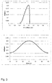
- Fig. 3 the calculated reflection for a grating with a period of 0.62 ⁇ m and a depth D GK of 0.2 ⁇ m as a function of the wavelength is shown in the upper part.
- the color impression achieved with this grid is red.
- the optimum depth D lit calculated for a wavelength ⁇ of 0.63 ⁇ m according to equation (1) is theoretically 0.303 ⁇ m, so that according to equation (2) the correction factor k is 0.66.
- the calculated reflection is given as a function of the viewing angle. As can be clearly seen, the highest reflection is achieved for a viewing angle close to 0 °, ie, when viewed almost perpendicularly. When the viewing area is changed from -30 ° to 30 °, the reflection changes by less than 20%.
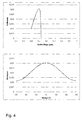
- Fig. 4 the calculated reflection for a grating with a period of 0.53 ⁇ m and a depth D GK of 0.165 ⁇ m as a function of the wavelength is shown in the upper part.
- the color impression achieved with this grid is green.
- the optimum depth D lit calculated for a wavelength ⁇ of 0.53 ⁇ m according to equation (1) is theoretically 0.25 ⁇ m, so that according to equation (2) the correction factor k is 0.66.
- the calculated reflection is given as a function of the viewing angle. As can be clearly seen, the highest reflection is achieved for a viewing angle close to 0 °, ie, when viewed almost perpendicularly.
- the reflection changes by less than 20%.
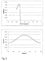
- Fig. 5 the calculated reflection for a grating with a period of 0.49 ⁇ m and a depth D GK of 0.145 ⁇ m as a function of the wavelength is shown in the upper part.
- the color impression achieved with this grid is blue.
- the optimum depth D lit calculated for a wavelength ⁇ of 0.53 ⁇ m according to equation (1) is theoretically 0.226 ⁇ m, so that according to equation (2) the correction factor k amounts to 0.64.
- the calculated reflection is given as a function of the viewing angle. As can be clearly seen, the highest reflection is achieved for a viewing angle close to 0 °, ie, when viewed almost perpendicularly. When the viewing area is changed from -30 ° to 30 °, the reflection changes by less than 20%.
- Fig. 6 to illustrate the so-called "moth eye effect" at the top of a calculated reflection spectrum for a wavelength ⁇ of 0.5 microns for a grid with the period 0.25 microns, a depth of 0.3 microns. Due to the nanostructuring of the surface through the grid, only a very small reflection is achieved.
- a calculated reflection spectrum for a grating having a period of 0.25 ⁇ m and a depth of 0.1 ⁇ m for a wavelength ⁇ of 0.5 ⁇ m is also shown. Again, an extremely low reflection is achieved.
- Fig. 7 schematically in the upper part of a glass ceramic 1 with a plurality of laterally structured regions 5, shown here in troughs 20, shown, in which case the laterally structured regions 5 are not designated, since they completely cover the region 20 of the upper surface 2 of the glass ceramic 1 ie in In this example, the areas 5 are identical to the wells 20. Also designated is the line A, along which a section was made through the glass-ceramic 1, this section in the lower part of Fig. 7 is shown.
- the troughs 20 have per se periodic and / or quasi-periodic structures 6, for example in the form of a micro and / or nanostructure, which were each realized by laser ablation.
- 20 ceramic colors may be located in the wells, each of which may cover the entire well 20 or even a portion of it, wherein the color penetration has been realized with a laser. It is also possible that in each case only a portion of the wells is provided with periodic and / or quasi-periodic structures 6. Furthermore, under the wells 20 may be a light source and / or a sensor. The glass ceramic has two surfaces, namely the top 2 and the bottom 3. The bottom 3 of the glass ceramic 1 is in Fig. 7 but shown as smooth, but can also be knobbed. Such a laterally structured region 5 formed in a trough 20 increases the user-friendliness of the cooking surface through the haptic support of the operation.
- luminous sources are located underneath the depressions, it is furthermore possible to optimize them by the appropriate structuring of the laterally structured region 5 by means of periodic and / or quasi-periodic structures 6 with regard to their focusing or defocusing of the light, and thus further the user-friendliness of the light Cooking surface to improve.
- a section along the section line designated A This in particular shows the shape of the wells 20.
- the wells 20 thus have a surface which has a curvature, ie is not flat, in which case a curvature is understood to mean a curvature having a radius of curvature of at least 1 mm or more.
- Fig. 8 is schematically in the upper part of a wok glass ceramic 1 with a laterally structured region 5 (not labeled), here formed in a trough 20, shown, in which case the laterally structured region 5 are not designated, since he designed as a trough 20 area the top 2 of the glass ceramic 1 completely covered, ie in this example the area 5 is identical to the trough 20, and in the lower area a section through the glass ceramic 1 along the top of the Fig. 8
- the depression 20 has periodic and / or quasi-periodic structures 6, for example in the form of a microstructure and / or nanostructure, which have each been realized by laser ablation.
- 20 ceramic colors may be in the trough, wherein the color penetration has been realized with a laser.
- a light source and / or a sensor can be located under the trough 20.
- the glass ceramic 1 has two surfaces, namely the top 2 and the bottom 3.
- the bottom 3 of the glass ceramic 1 is in Fig. 7 but shown as smooth, but can also be knobbed.
- the overall curved shape of the glass-ceramic becomes clear, so that Here, the glass ceramic is present in the form of a 3D molded body.
- the curved surface of the glass ceramic in the trough 20 can be seen.
- the curvature here is understood as a curvature which has a radius of curvature of at least 1 mm or more.
- Fig. 9 shows a schematic representation of drops 12 in different areas 30, 40 and 50 on the upper side 2 of a glass ceramic 1.
- the underside 3 of the glass ceramic 1 is here shown smooth, but can also be designed genoppt or otherwise structured.
- the contact angle of the drop 12 is less than 80 °, and the drop 12 spreads on the surface 32 of the region 30. It is also said that such a surface 32 is hydrophilic and good Wettability has.
- a second drop 12 is shown in the central region 40 of the glass ceramic 1. This has to the surface 42 of the area 40 on a contact angle between 80-120 °. This is called surface 42 has hydrophobic properties. This may be the case, for example, if the surface 42 for hydrophobization has been provided with a silanization layer.
- a third drop 12 is shown in the right area 50 of the glass ceramic 1. This has to the surface 52 of the region 50 of the glass ceramic 1 to a contact angle of 120 ° or more. The drop 12 thus hardly wets the surface 52. The surface 52 thus has a so-called Super hydrophobicity on.
- Such superhydrophobicity can be realized by suitable structuring of a surface, for example in the form of periodic and / or quasiperiodic structures 6 (not shown).
- Fig. 10 shows a schematic representation of periodic and / or quasi-periodic structures 6 in a laterally structured region 5 of the glass ceramic 1, which are located on the upper side 2 of the glass ceramic 1.
- the bottom 3 of the glass ceramic 1 is shown here smooth, but can also be studded.
- not all structures 6 have been designated.
- the structures 6 do not protrude beyond the original surface of the glass ceramic and are located within the amorphous surface zone of the glass ceramic. Furthermore, they are characterized by a period a and a width b of the structure.
- the terms "period of the structure”, “period of the structures” and “period structure” are used synonymously in the context of this invention, as are the terms “width of the structures", “width of the structure” and “structure width”.
- 2D lattices which have a ratio of b: a of 0.4 to 0.6 are preferred.
- the ratio of structure width b to period structure a is also called the duty cycle.
- structures are particularly suitable which have non-rectangular edges, such as pyramidal, cylindrical and / or trapezoidal structures with rounded edges.
Abstract
Die Erfindung betrifft eine Glaskeramik (1), aufweisend eine Oberseite (2) und eine Unterseite (3) sowie eine Oberflächenzone von mindestens 10 nm Dicke, die im Wesentlichen amorph vorliegt, dergestalt, dass in der Oberflächenzone höchstens als 20 Vol.-% kristalline Phasen enthalten sind. Die Glaskeramik (1) weist mindestens eine laterale Strukturierung (5) auf, die in sich periodische und/oder quasiperiodische Strukturen (6) mit einem mittleren Strukturabstand von höchstens 200 µm aufweist. Die Strukturen (6) sind als Vertiefungen im Material der Oberflächenzone ausgebildet, so dass sie insgesamt nicht aus der Ebene der Oberfläche herausragen. Ihre Tiefe ist geringer als die Dicke der Oberflächenzone und reicht nicht in den Bereich der Glaskeramik (1) mit einem höheren Kristallphasengehalt hinein.The invention relates to a glass ceramic (1) comprising an upper side (2) and a lower side (3) and a surface zone of at least 10 nm thickness, which is substantially amorphous, such that at most 20% by volume crystalline in the surface zone Phases are included. The glass ceramic (1) has at least one lateral structuring (5) which has periodic and / or quasi-periodic structures (6) with an average structure spacing of at most 200 μm. The structures (6) are formed as depressions in the material of the surface zone, so that they do not project out of the plane of the surface as a whole. Their depth is less than the thickness of the surface zone and does not reach into the region of the glass ceramic (1) with a higher crystalline phase content.
Description
Die Erfindung betrifft eine Glaskeramik mit besonders ausgestalteter Oberfläche sowie ein Verfahren zur deren Herstellung.The invention relates to a glass ceramic with a specially designed surface and to a method for the production thereof.
Glaskeramiken werden heute in zahlreichen Anwendungen eingesetzt. Bedingt durch seine mögliche Nullausdehnung und der hohen thermischen, mechanischen und chemischen Beständigkeit, werden Glaskeramiken insbesondere in der Halbleiterindustrie in Steppern und Belichtungsgeräten, in der Astronomie als Spiegelträger und in der Home Tech Industrie als Kaminsichtscheibe oder als Kochfläche eingesetzt.Glass ceramics are used today in numerous applications. Due to its possible zero expansion and the high thermal, mechanical and chemical resistance, glass ceramics are used in particular in the semiconductor industry in steppers and exposure equipment, in astronomy as a mirror support and in the home tech industry as a fireplace view panel or cooking surface.
Glaskeramikkochflächen sind dem Markt seit langer Zeit bekannt, beispielsweise die CERAN®-Felder der SCHOTT AG.Glass ceramic cooking surfaces have been known to the market for a long time, for example the CERAN® fields of SCHOTT AG.
Um als Kochfläche geeignet zu sein, muss eine Glaskeramik eine Reihe von Anforderungen erfüllen. Beispielsweise ist ein geringer thermischer Ausdehnungskoeffizient (α< 0,5 * 10-6 K-1, 20-700°C), eine geringe thermische Leitfähigkeit (k < 2,4 W/(m*K), sowie eine hohe Temperaturunterschiedsfestigkeit notwendig, damit die hohen Temperaturunterschiede, die zwischen beheizten Bereichen und nicht beheizten Bereichen einer Kochfläche auftreten, nicht zum Versagen des Kochfeldes durch Bruch führen. Auch an die Bruchfestigkeit einer Glaskeramik werden hohe Anforderungen gestellt, wobei als Bruchfestigkeit hier die Festigkeit der Glaskeramik gegenüber Belastungen von oben, beispielsweise gegenüber einem unsanft auf die Oberfläche gestellten Topf, bezeichnet ist.In order to be suitable as a cooking surface, a glass ceramic must meet a number of requirements. For example, a low thermal expansion coefficient (α <0.5 * 10 -6 K -1 , 20-700 ° C), a low thermal conductivity (k <2.4 W / (m * K), and a high temperature difference resistance is necessary so that the high temperature differences that occur between heated areas and unheated areas of a cooking surface, Do not cause failure of the hob due to breakage. High demands are also placed on the breaking strength of a glass ceramic, with the strength of the glass ceramic being referred to stress from above, for example, in relation to a pot unsightly placed on the surface.
So beschreibt beispielsweise die
Neben den hohen Anforderungen, die sowohl an die Festigkeit der Glaskeramik als auch an die mechanische und chemische Beständigkeit der darauf angebrachten Markierungen gestellt werden, werden in den letzten Jahren auch verstärkt zusätzliche Eigenschaften von Kochflächen bzw. Glaskeramiken angefragt, die die Bedienerfreundlichkeit eines Kochfeldes erhöhen sollen. Dazu zählen insbesondere Oberflächen mit einer erleichterten Reinigbarkeit, die Verringerung der Sichtbarkeit beispielsweise von Fingerabdrücken auf der Kochfläche oder die Unterbindung störender Reflexionen. Für all diese Punkte sind unterschiedliche Lösungen, beispielsweise in Form von Oberflächenbehandlungen oder Beschichtungen, vorgeschlagen worden.In addition to the high demands placed on the strength of the glass ceramic as well as on the mechanical and chemical resistance of the markings applied thereto, in recent years more and more additional properties of cooking surfaces or glass ceramics have been requested which are intended to increase the user friendliness of a hob , These include, in particular, surfaces with easier cleanability, the reduction in the visibility, for example, of fingerprints on the cooking surface or the ligation disturbing reflections. For all these points, different solutions have been proposed, for example in the form of surface treatments or coatings.
So ist beispielsweise die Erzeugung einer rauen Oberfläche durch einen Ätzprozess möglich. Ein Ätzen einer Glasoberfläche erfolgt dabei meist nasschemisch mittels Flusssäure und stellt somit ein Verfahren dar, bei dem erhebliche Verfahrensrisiken auftreten. Auf diese Weise ist weiterhin auch keine laterale Strukturierung der Oberfläche möglich, da beim Ätzen der Angriff auf die gesamte Oberfläche gleichmäßig erfolgt. Es handelt sich hier um kein gerichtetes Strukturierungsverfahren (anisotroper Ätzprozess), sondern um ein homogenes Strukturierungsverfahren, welches keine scharfen Kanten erzeugt. Anisotrope Ätzverfahren, wie das Ionenstrahlätzen, sind technisch sehr aufwendig, weil ein Vakuum vorhanden sein muss, und damit sehr teuer.For example, the production of a rough surface by an etching process is possible. Etching of a glass surface is usually wet chemical using hydrofluoric acid and thus represents a method in which significant process risks occur. In this way, furthermore, no lateral structuring of the surface is possible since the attack on the entire surface takes place uniformly during etching. This is not a directed structuring method (anisotropic etching process), but a homogeneous structuring method that does not produce sharp edges. Anisotropic etching processes, such as ion beam etching, are technically very complicated because a vacuum must be present, and thus very expensive.
Eine andere Möglichkeit der Oberflächenstrukturierung eines Glases stellt das Einbringen von Strukturierung direkt im Anschluss an den Heißformgebungsprozess mittels einer Walze dar. Auf diese Weise sind allerdings keine lateral strukturierten Bereiche erhältlich, vielmehr wird die gesamte Oberfläche des Glasbandes gleichmäßig mit einer Struktur versehen. Weiterhin liefern Walzverfahren bei Gläsern und Glaskeramiken keine definierten Nanostrukturen, weil bedingt durch die hohe Bearbeitungstemperatur und die damit verbundene Oberflächenspannung die Strukturen verrunden.Another possibility of surface structuring of a glass is the introduction of structuring directly after the hot forming process by means of a roller. In this way, however, no laterally structured regions are available, but the entire surface of the glass ribbon is uniformly provided with a structure. Furthermore, rolling processes for glasses and glass ceramics do not provide any defined nanostructures because the structures round due to the high processing temperature and the surface tension associated therewith.
Die Herstellung haptischer Schichten auf einem Substrat ist weiterhin aus der
Die
Die
Aus der
Die
All den vorgenannten Lösung ist dabei gemein, dass sie eine Reihe gravierender Nachteile aufweisen. So sind in der Regel die vorgeschlagenen Beschichtungen nicht ausreichend kratzfest, um herkömmlichen Reinigungsverfahren für Kochfelder, beispielsweise mit Hilfe eines Schabers zur Entfernung eingebrannter Rückstände, zu überstehen, und/oder weisen eine nicht ausreichende Temperaturbeständigkeit, insbesondere im Heißbereich der Kochfläche, also in den eigentlichen Kochzonen, auf. Beschädigungen der Schichten, beispielsweise durch zu hohe mechanische oder thermische Belastung, sind darüber hinaus in der Regel störend sichtbar. Sollen die Funktionsschichten nur lokal, d.h. lateral strukturiert, aufgetragen werden, besteht die Notwendigkeit aufwendiger und technisch noch nicht ausreichend beherrschter Strukturierungsverfahren. Zu guter Letzt ergeben sich Schwierigkeiten bei der Integration solcher Beschichtungen in den Produktionsablauf, da eine vollflächige Beschichtung eines Kochfeldes mit einer Funktionsschicht in der Regel nach Schritten mit hoher thermischer Belastung wie der Keramisierung und einem ggf. nachträglich erfolgten Einbrand eines Dekors, einem sogenannten Sekundäreinbrand, erfolgen muss. Damit ergibt sich allerdings auch die Problematik der Beschichtung der Markierungen selbst, was an diesen Stellen häufig zu Schichtversagen in Folge von schlechter Haftung führen kann.All the aforementioned solution has in common that they have a number of serious disadvantages. Thus, in general, the proposed coatings are not sufficiently scratch-resistant to survive conventional cleaning methods for hobs, for example with the aid of a scraper to remove baked residues, and / or have insufficient temperature resistance, especially in the hot area of the cooking surface, ie in the actual Cooking zones, on. Damage to the layers, for example, due to excessive mechanical or thermal stress, are also usually disturbing visible. If the functional layers are to be applied only locally, ie laterally structured, there is a need for elaborate and technically not yet sufficiently well-controlled structuring methods. Finally, there are difficulties in the integration of such coatings in the production process, since a full-surface coating of a hob with a functional layer usually after steps with high thermal stress such as ceramization and possibly subsequently carried out a decor, a so-called secondary incineration, must be done. However, this also results in the problem of coating the markers themselves, which can often lead to layer failure as a result of poor adhesion at these points.
Weiterhin ist störend, dass je nachdem, welcher Effekt erzeugt ist, ein anderes Verfahren verwenden muss. So kann es fallweise notwendig sein, zur Erzeugung einer Oberfläche, die Bereiche mit verbesserter Reinigbarkeit, Bereiche mit farbiger Markierung von Kochzonen, Bereiche mit verminderter Oberflächenreflexion sowie Bereiche mit haptischen Eigenschaften aufweist, vier unterschiedliche Verfahren zur Anwendung zu bringen. Dies stellt einen immensen Aufwand dar und ist wirtschaftlich schwer umsetzbar.Furthermore, it is disturbing that, depending on which effect is generated, another method must be used. Thus, it may occasionally be necessary to use four different methods to produce a surface having areas of improved cleanability, areas of color marking of cooking zones, areas of reduced surface reflectance, and areas of haptic properties. This represents an immense effort and is economically difficult to implement.
Es ergibt sich somit die Notwendigkeit, lateral strukturierte Bereiche mit Markierungs- und/oder sonstigen funktionalen Eigenschaften wie erleichterter Reinigbarkeit oder verminderter Reflexion mit hoher thermischer und mechanischer Beständigkeit ohne Verminderung der Gesamtfestigkeit auf der Oberseite einer Glaskeramik bzw. eines aus einer Glaskeramik bestehenden Kochfeldes in einem wirtschaftlichen Verfahren bereitzustellen.The result is thus the necessity of laterally structured regions with marking and / or other functional properties such as improved cleanability or reduced reflection with high thermal and mechanical resistance without reducing the overall strength on the upper side of a glass ceramic or of a glass ceramic cooktop in one provide economic method.
Die Erfindung hat zur Aufgabe, eine Glaskeramik mit lateral strukturierten Funktionsbereichen auf mindestens einer ihrer Oberflächen, sowie ein Verfahren zur Herstellung einer Glaskeramik mit lateral strukturierten Funktionsbereichen auf mindestens einer ihrer Oberflächen bereitzustellen.It is an object of the invention to provide a glass ceramic with laterally structured functional areas on at least one of its surfaces, and also a method for producing a glass ceramic with laterally structured functional areas on at least one of its surfaces.
Die erfindungsgemäße Aufgabe wird durch eine Glaskeramik, ein Glaskeramikprodukt wie z.B. ein Glaskeramikkochfeld, sowie ein Verfahren zur Herstellung einer erfindungsgemäßen Glaskeramik bzw. eines Glaskeramikkochfeldes gemäß den unabhängigen Ansprüchen gelöst. Weiterbildungen der Erfindung sowie vorteilhafte Ausführungsformen finden sich in den jeweiligen Unteransprüchen.The object according to the invention is achieved by a glass ceramic, a glass-ceramic product, e.g. a glass ceramic hob, and a method for producing a glass ceramic or a glass ceramic hob according to the invention solved according to the independent claims. Further developments of the invention and advantageous embodiments can be found in the respective subclaims.
Die erfindungsgemäße Aufgabe wird überraschend einfach durch eine Glaskeramik gelöst, bei der mindestens eine Oberfläche der Glaskeramik mindestens einen lateral strukturierten Bereich, der in sich periodische und/oder quasiperiodische Strukturen mit einem mittleren Strukturabstand von 200 µm oder weniger, beispielsweise ausgebildet als Mikro- und/oder Nanostrukturen, umfasst, aufweist. Weiterhin wird diese Aufgabe gelöst durch eine Glaskeramik, bei der mindestens eine Oberfläche der Glaskeramik mindestens einen lateral strukturierten Bereich aufweist, wobei die Strukturen hierbei Linien und/oder Flächen sind.The object according to the invention is achieved surprisingly simply by a glass ceramic in which at least one surface of the glass ceramic has at least one laterally structured region which has periodic and / or quasi-periodic structures with an average structure spacing of 200 μm or less, for example formed as micro- and / or or nanostructures. Furthermore, this object is achieved by a glass ceramic in which at least one surface of the glass ceramic has at least one laterally structured region, the structures being lines and / or surfaces.
Als lateral strukturiert wird ein Bereich im Rahmen der vorliegenden Erfindung bezeichnet, der auf der mindestens einen Oberfläche der Glaskeramik eine bestimmte, räumlich genau definierte Ausdehnung besitzt und an andere Bereiche angrenzt, die eine andere Struktur der Oberfläche aufweisen. Insbesondere können diese anderen Bereiche der ursprünglichen Glaskeramik entsprechen, mit einer herkömmlichen keramischen Dekorfarbe versehen sein oder ebenfalls Nanostrukturen aufweisen, die allerdings hinsichtlich ihrer genauen Ausprägung von der des ersten Bereiches verschieden sind.Laterally structured is a region in the context of the present invention which has a specific, spatially precisely defined extent on the at least one surface of the glass ceramic and adjoins other regions which have a different structure of the surface. In particular, these other areas may correspond to the original glass ceramic, be provided with a conventional decorative ceramic paint or also have nanostructures, which are, however, different in terms of their exact form of the first area.
Die Herstellung einer Glaskeramik erfolgt im Regelfall durch eine Temperaturbehandlung (Keramisierung) eines geeigneten Ausgangsglases, des sog. Grünglases. Die erfindungsgemäßen Glaskeramiken sind nicht auf die ausgeführten Beispiele beschränkt, es handelt sich hier um besonders bevorzugte Glaskeramikzusammensetzungen, die die Zusammensetzungsangaben in Gew.-% enthalten können.The production of a glass ceramic is usually carried out by a temperature treatment (ceramization) of a suitable starting glass, the so-called. Green glass. The glass-ceramics according to the invention are not limited to the examples described, these are particularly preferred glass-ceramic compositions which may contain the composition details in% by weight.
- Al2O3 18-25 %Al 2 O 3 18-25%
- SiO2 50-72 %SiO 2 50-72%
-
Li2O 0, 1-10, 0 %Li 2
O 0, 1-10, 0% - K2O 0-3 %K 2 O 0-3%
- Na2O 0-3 %Na 2 O 0-3%
- MgO 0-3 %MgO 0-3%
- P2O5 0-1 %P 2 O 5 0-1%
- SnO2 0-1 %SnO 2 0-1%
-
TiO2 1, 0-5 %
TiO 2 1, 0-5% -
ZrO2 0, 5 -3, 0 %
ZrO 2 0, 5 -3, 0% - ZnO 0-5 %ZnO 0-5%
- Al2O3 2-25 %Al 2 O 3 2-25%
- SiO2 60-85 %SiO 2 60-85%
- Li2O 5-15%Li 2 O 5-15%
- K2O+Na2O 0-8 %K 2 O + Na 2 O 0-8%
Die Glaskeramik in der vorliegenden Erfindung verfügt vorzugsweise über eine ausgebildete Oberflächenzone von mindestens 10 nm Dicke, die im Wesentlichen amorph vorliegt. Im Rahmen der vorliegenden Erfindung bedeutet die im Wesentlichen amorphe Ausformung der Oberflächenzone, dass in der Oberflächenzone nicht mehr als 20 Vol.-% kristalline Phasen enthalten sind. Gegebenenfalls kann eine solche glasige Oberflächenzone auch nur auf einer der Oberflächen vorhanden sein, oder eine der Oberflächenzone weist eine geringere Dicke als die vorgenannten 10 nm auf. Ohne Beschränkung auf das dargestellte Beispiel sind Lithium-Aluminosilikat-Glaskeramiken für die Erfindung besonders geeignet. Bei diesem Glaskeramik-Typ kann eine glasige Oberflächenzone mit einem geringen Kristallphasengehalt von höchstens 20 Volumenprozent leicht bei der Keramisierung des Ausgangsglases ausgebildet werden, wobei sich typischerweise eine Lithium-Verarmung in der Oberflächenzone ausbildet. Bei diesem Glaskeramik-Typ ist also die Oberflächenzone 8 durch einen relativ zum inneren Glaskeramikmaterial 10 niedrigeren Lithium-Gehalt gekennzeichnet.The glass-ceramic in the present invention preferably has a formed surface zone of at least 10 nm in thickness, which is substantially amorphous. In the context of the present invention, the substantially amorphous formation of the surface zone means that not more than 20% by volume of crystalline phases are contained in the surface zone. Optionally, such a glassy surface zone may also be present on only one of the surfaces, or one of the surface zones has a smaller thickness than the aforementioned 10 nm. Without being limited to the illustrated example, lithium aluminosilicate glass-ceramics are particularly suitable for the invention. In this type of glass-ceramic, a glassy surface zone having a low crystal phase content of at most 20% by volume can be easily formed upon ceramization of the starting glass, typically forming lithium depletion in the surface zone. In this type of glass ceramic, therefore, the
Bei der Glaskeramik kann es sich um eine Platte, einen 3D-Formkörper und/oder um eine Platte mit Aussparungen oder Vertiefungen, die zum Beispiel in Form von Mulden ausgebildet sind, handeln.The glass ceramic can be a plate, a 3D molded body and / or a plate with recesses or depressions, which are formed in the form of depressions, for example.
Als Mikrostrukturen werden im Rahmen der vorliegenden Erfindung Strukturen verstanden, deren Strukturbreite kleiner als 200 µm sind. Als Nanostrukturen werden im Rahmen der vorliegenden Erfindung Strukturen verstanden, deren Strukturbreite kleiner als 1 µm sind.In the context of the present invention, microstructures are structures whose structure widths are smaller than 200 μm. In the context of the present invention, nanostructures are structures whose structure widths are smaller than 1 μm.
Bevorzugt beträgt die Strukturtiefe der Mikro- und/oder Nanostrukturen 500 nm oder weniger.The structural depth of the microstructures and / or nanostructures is preferably 500 nm or less.
Als Strukturbreite wird dabei in der vorliegenden Erfindung der mittlere Abstand der Strukturen bezeichnet.In the present invention, the average spacing of the structures is referred to as structure width.
In einer weiteren Ausführungsform der Erfindung beträgt die Breite der Strukturen weniger als 0,8 µm, bevorzugt weniger als 500 nm und liegt besonders bevorzugt zwischen 1 und 400 nm.In a further embodiment of the invention, the width of the structures is less than 0.8 μm, preferably less than 500 nm, and is particularly preferably between 1 and 400 nm.
Besonders bevorzugt sind die Strukturen als Nanostrukturen ausgebildet.The structures are particularly preferably designed as nanostructures.
Insbesondere ist die Strukturtiefe der Mikro- und/oder Nanostrukturen in den lateral strukturierten Oberflächenbereichen der mindestens einen Seite der Glaskeramik so ausgebildet, dass die Strukturen innerhalb der im Wesentlichen amorph ausgebildeten Oberflächenzone der Glaskeramik liegen. Die Mikro- und/oder Nanostrukturen ragen somit nicht in Bereiche der Glaskeramik hinein, in denen ein höherer Gehalt an Kristallphasen als 20 Vol.-% vorliegt. Auf diese Weise sind sehr feine Strukturen möglich, die nicht durch das Vorliegen von Kristallen gestört, d.h. insbesondere die Kantengenauigkeit der Strukturen verändern und die Oberflächenrauhigkeiten erhöhen. Ein weiterer Vorteil dieser Ausführungsform liegt darin, dass auf diese Weise trotz des Vorliegens lateral strukturierter Oberflächenbereiche, die in sich periodische und/oder quasiperiodische Strukturen mit einem mittleren Strukturabstand von höchstens 200 µm, beispielsweise in Form von Mikro- und/oder Nanostrukturen, aufweisen, die im Wesentlichen amorph ausgebildete Oberflächenzone der Glaskeramik nicht gestört wird, so dass insgesamt die Festigkeit der Glaskeramik erhalten bleibt.In particular, the structure depth of the microstructures and / or nanostructures in the laterally structured surface regions of the at least one side of the glass ceramic is designed so that the structures lie within the substantially amorphous surface zone of the glass ceramic. The microstructures and / or nanostructures thus do not protrude into regions of the glass ceramic, in which has a higher content of crystal phases than 20% by volume. In this way, very fine structures are possible, which are not disturbed by the presence of crystals, ie in particular change the edge accuracy of the structures and increase the surface roughness. A further advantage of this embodiment is that, in this way, despite the presence of laterally structured surface regions which in themselves have periodic and / or quasi-periodic structures with an average structure spacing of at most 200 μm, for example in the form of microstructures and / or nanostructures, the substantially amorphous surface zone of the glass ceramic is not disturbed, so that overall the strength of the glass ceramic is maintained.
Die lateral strukturierten, in sich periodische und/oder quasiperiodische Strukturen mit einem mittleren Strukturabstand von höchstens 200 µm aufweisenden Oberflächenbereiche der erfindungsgemäßen Glaskeramik sind als funktionale Oberflächen ausgebildet. Sie weisen einen Farbeindruck, beziehungsweise optische Filtereigenschaften und/oder eine verbesserte Reinigbarkeit und/oder Antireflexeigenschaften und/oder haptische Eigenschaften auf.The laterally structured, inherently periodic and / or quasiperiodic structures with an average structure spacing of at most 200 μm having surface regions of the glass-ceramic according to the invention are designed as functional surfaces. They have a color impression or optical filter properties and / or improved cleanability and / or antireflection properties and / or haptic properties.
Werden Felder mit Bereichen, die einen Farbeindruck und/oder eine Mattierung aufweisen, auf mindestens einer Seite einer Glaskeramik entsprechend der vorliegenden Erfindung hergestellt, so erfolgt dies über die Ausbildung spezieller nano- oder mikrostrukturierte Bereiche. Eine Beschichtung der Glaskeramik bzw. des korrespondierenden Grünglases mit einer keramischen Farbe sowie daran anschließendem Einbrand der Farbe ist nicht mehr notwendig. Werden solche einen Farbeindruck und/oder eine Mattierung aufweisenden Bereiche auf einer Glaskeramik mit den in dieser Erfindung vorliegenden Verfahren erzeugt, ist somit auch kein weiteres Material und kein weiteres Verfahren, insbesondere auch kein Beschichtungsverfahren, zur Erzeugung der Funktionalität notwendig.If fields having areas which have a color impression and / or a matting are produced on at least one side of a glass ceramic according to the present invention, this takes place via the formation of special nano- or microstructured areas. A coating of the glass ceramic or of the corresponding green glass with a ceramic color and thereon subsequent penetration of the paint is no longer necessary. If such areas having a color impression and / or a matting are produced on a glass ceramic with the methods present in this invention, then no further material and no further method, in particular also no coating method, is necessary for the production of the functionality.
Dies gilt auch, wenn andere als Farb- oder Mattierungseffekte in den lateral strukturierten Bereichen erzeugt werden sollten. Auch hier bleibt nach der Behandlung die chemische und Temperaturfestigkeit des zugrunde liegenden Materials erhalten. Die makroskopischen Effekte werden lediglich durch eine Nanostrukturierung in den lateral strukturierten Bereichen erzeugt.This is also true if other than color or matting effects should be generated in the laterally structured areas. Again, the chemical and temperature resistance of the underlying material is retained after treatment. The macroscopic effects are only generated by a nanostructuring in the laterally structured regions.
Zur Erzeugung eines Farbeindrucks mittels des in der vorliegenden Erfindung vorgestellten Verfahrens in den lateral strukturierten Bereichen der Oberfläche einer Glaskeramik Gitterstrukturen erzeugt. Werden Gitterstrukturen mit einer Periode der Gitterstrukturen, A, die ungefähr gleich der Wellenlänge des Lichts, λ, ist, erzeugt, so wird nur eine bestimmte Farbe in die 1. Ordnungen reflektiert. Andere Ordnungen sind nicht mehr vorhanden, da der Beugungswinkel nun >90° beträgt. Die 0. Ordnung wird unterdrückt. Notwendig sind hierfür bestimmte Strukturtiefen.In order to produce a color impression by means of the method presented in the present invention, grating structures are produced in the laterally structured regions of the surface of a glass-ceramic. When lattice structures having a period of the lattice structures, A, which is approximately equal to the wavelength of the light, λ, are generated, only a certain color is reflected in the 1st orders. Other orders are no longer available because the diffraction angle is now> 90 °. The 0th order is suppressed. Necessary for this are certain structural depths.
Überraschend hat sich gezeigt, dass im Gegensatz zu der in den Lehrbüchern (beispielsweise Microoptics, Sinzinger und Jahns, Seite 138 ff.) publizierten optimalen Tiefe D für Reflexionsgitter sich bei der Strukturierung der Glaskeramik für optimale Ergebnisse abweichende Werte erhalten werden. So gilt für die optimale Tiefe D einer Reflexionsstruktur nach der Literatur: ![]()
![]()
![]()
![]()
In der Regel wird auf diese Weise eine mosaikartige Anordnung kleiner Bereiche erzeugt. Diese rufen aufgrund einer speziellen Nanostrukturierung einen Farbeindruck beim Betrachter hervor. Überraschenderweise ist dieser Farbeindruck überwiegend winkelunabhängig. Unter überwiegend unabhängig wird dabei verstanden, dass sich die reflektierte Intensität in einem Winkelbereich von -30 Grad bis 30 Grad um weniger als 20% ändert.As a rule, a mosaic-like arrangement of small areas is produced in this way. These cause a color impression in the viewer due to a special nanostructuring. Surprisingly, this color impression is predominantly angle-independent. The term "largely independent" is understood to mean that the reflected intensity changes by less than 20% in an angular range of -30 degrees to 30 degrees.
Die Kombination vieler dieser Felder, erzeugt in einer Art Mosaik, ermöglicht die Erzeugung vieler Farben im RGB-Farbraum. Vorzugsweise sollte die laterale Ausdehnung dieser kleinen Farbbereiche kleiner sein als die Auflösungsgrenze des Auges, also kleiner 20 µm. Auch möglich ist es aber, ein großes Feld mit einem speziellen Farbeindruck zu realisieren. Die Geometrie ist nicht notwendig auf Rechtecke beschränkt, sondern kann auch Bilder, Formen oder Texte darstellen. Gemäß einer Ausführungsform der Erfindung wird also eine laterale Strukturierung vorgesehen, welche mehrere Bereiche oder Felder mit unterschiedlichen optischen Gittern umfasst.The combination of many of these fields, created in a kind of mosaic, allows the generation of many colors in the RGB color space. Preferably, the lateral extent of these small color areas should be smaller than that Resolution limit of the eye, so less than 20 microns. But it is also possible to realize a large field with a special color impression. The geometry is not necessarily limited to rectangles, but can also represent images, shapes or texts. According to one embodiment of the invention, therefore, a lateral structuring is provided, which comprises a plurality of regions or fields with different optical gratings.
Ist die Periode Λ des Gitters um ein Vielfaches größer als die Wellenlänge des Lichts, λ, werden mehrere Ordnungen reflektiert, und man erhält ein sogenanntes Regenbogenspektrum.If the period Λ of the lattice is many times greater than the wavelength of the light, λ, several orders are reflected and a so-called rainbow spectrum is obtained.
Auf ähnliche Weise wie ein Farbeindruck lässt sich nach der vorliegenden Erfindung auch eine verbesserte Reinigbarkeit der Oberfläche einer Glaskeramik in einem entsprechend strukturierten Oberflächenbereich erzeugen.In a manner similar to a color impression, it is also possible according to the present invention to produce an improved cleanability of the surface of a glass ceramic in a correspondingly structured surface area.
Dies geschieht vorteilhaft dadurch, dass in die Oberfläche der Glaskeramik Nanostrukturen eingebracht werden. Hier kommt es dann zum bekannten Effekt der Superhydrophobie, die zuweilen auch als "Lotuseffekt" bezeichnet ist. Durch die Nanostruktur der betreffenden Oberfläche, in der Natur beispielsweise das Blatt der Lotuspflanze, besteht nur ein sehr geringer Kontakt zwischen der Oberfläche selbst, nämlich nur an den "Strukturspitzen" und dem Wasser. Dies behält daher seine Kugelform bei, so dass die Adhäsionskräfte zwischen Wasser und Oberfläche auf ein Minimum reduziert sind. Auch Schmutzpartikel selbst haften nur wenig, da auch hier die Kontaktfläche zwischen Schmutzpartikel und Oberfläche minimiert ist. Das abrollende Wasser kann damit die Schmutzpartikel leicht mitführen, so dass insgesamt die Reinigbarkeit einer solcherart ausgerüsteten Oberfläche deutlich erhöht ist.This is advantageously done by introducing nanostructures into the surface of the glass-ceramic. Here then it comes to the well-known effect of superhydrophobia, which is sometimes referred to as "lotus effect". Due to the nanostructure of the surface in question, in nature, for example, the leaf of the lotus plant, there is only a very small contact between the surface itself, namely only on the "structure peaks" and the water. This therefore maintains its spherical shape, so that the adhesion forces between water and surface are reduced to a minimum. Even dirt particles themselves adhere only slightly, since here too the contact surface between dirt particles and surface is minimized. The Rolling water can thus easily carry the dirt particles, so that overall the cleanability of such a surface equipped is significantly increased.
Zur Charakterisierung der Oberfläche und insbesondere zur Feststellung ihrer Hydrophobie respektive Hydrophilie verwendet man üblicherweise den Kontakt- oder auch Benetzungswinkel. Für eine Oberfläche mit Superhydrophobie erhält man dabei einen Kontaktwinkel von größer 120°. Gemessen werden kann dieser Wert beispielsweise mit einem Goniometer. Die Bestimmung erfolgt visuell bei Betrachtung des Tropfens von der Seite. Weiter unten sind in
Weiterhin sind erfindungsgemäß auch Oberflächen mit einer reduzierten Reflexion leicht herzustellen. Dies erfolgt ebenfalls über das Einbringen von Nanostrukturen in die Oberfläche, wobei eine solche Mikrostrukturierung auch in Anlehnung an die Oberflächenstruktur von Insektenaugen als "Mottenaugenstruktur" bezeichnet wird. Diese Strukturen ähneln einem periodischen hexagonalen Oberflächenreliefgitter, sind als 2D-Gitter angeordnet und haben eine Periode von ungefähr 230 nm. Ist die Strukturperiode kleiner als die Wellenlänge des Lichtes, kann sich nur die 0. Beugungsordnung in Reflexion und Transmission ausbreiten, und das Licht tritt durch die strukturierte Oberfläche wie durch eine plane Grenzfläche, was bedeutet, dass das Gebiet als optisch homogen betrachtet und mit einer homogenen effektiven Brechungszahl beschrieben werden kann.Furthermore, surfaces with a reduced reflection are also easy to produce according to the invention. This is also done by introducing nanostructures into the surface, such microstructuring also being referred to as the "moth-eye structure" in accordance with the surface structure of insect eyes. These structures resemble a periodic hexagonal surface relief grating, are arranged as 2D grids and have a period of approximately 230 nm. If the pattern period is smaller than the wavelength of the light, only the 0th diffraction order can propagate in reflection and transmission and the light passes through the structured surface as through a plane interface, which means that the area can be considered optically homogeneous and described with a homogeneous effective refractive index.
Weiterhin kann eine erfindungsgemäße Glaskeramik auch laterale Strukturierungen aufweisen, die durch haptische Eigenschaften gekennzeichnet sind. Haptische Eigenschaften sind dabei Eigenschaften, die durch Berührung wahrgenommen werden.Furthermore, a glass ceramic according to the invention can also have lateral structurings which are characterized by haptic properties. Haptic properties are properties that are perceived by touch.
In einer weiteren Ausführungsform der Erfindung werden die lateral strukturierten, periodische und/oder quasiperiodische Strukturen mit einem mittleren Strukturabstand von höchstens 200 µm umfassenden Bereiche nicht nur in der Oberfläche der Glaskeramik selbst hergestellt, sondern können auch auf Bereichen erzeugt werden, die eine von der Glaskeramik abweichende Zusammensetzung aufweisen. Dabei kann es sich beispielsweise auch um die Oberfläche einer keramischen Farbe handeln, in die mittels des erfindungsgemäßen Verfahrens eine Mikro- und/oder Nanostrukturierung eingebracht wird.In a further embodiment of the invention, the laterally structured, periodic and / or quasiperiodic structures having an average structure spacing of at most 200 μm are not only produced in the surface of the glass ceramic itself, but can also be produced on regions which are one of the glass ceramic have different composition. This may, for example, also be the surface of a ceramic paint into which a microstructure and / or nanostructuring is introduced by means of the method according to the invention.
Vorteilhaft kann eine solche Strukturierung einer Dekorfarbe damit verbunden sein, dass der Einbrand der keramischen Farbe gleichzeitig erfolgt, also während der Strukturierung der Oberfläche durch das Strukturierungsverfahren selbst auch ein Einbrand der keramischen Farbe erfolgt.Advantageously, such a structuring of a decorative ink may be associated with the fact that the ceramic color is burned in at the same time, that is, during the structuring of the surface by the structuring method itself, a firing of the ceramic color takes place.
Bei dieser Kombination von Oberflächenstrukturierung und Farbeinbrand ist besonders auf die Einstellung der Leistungsparameter bei der Belichtung zu achten. Zweckmäßigerweise erfolgt die Belichtung durch einen Laser, wobei die Intensität des Laserspots räumlich variiert. Dieses sogenannte "Beamshaping" erfolgt dergestalt, dass der Laserstrahl in seinem Randbereich eine weniger hohe Energiedichte aufweist als in seiner Mitte, so dass eine Ortsauflösung der Intensitätsverteilung des Laserstrahls vorliegt. Die Intensitätsverteilung kann dabei ortsaufgelöst eine oder mehrere Stufen aufweisen oder auch einem komplizierteren Muster folgen, welches beispielsweise durch ein diffraktives optisches Element (DOE) vorgegeben sein kann.In this combination of surface structuring and color penetration, particular attention must be paid to the adjustment of the performance parameters during the exposure. Appropriately, the exposure is performed by a laser, wherein the intensity of the laser spot varies spatially. This so-called "beamshaping" takes place in such a way that the laser beam in its edge region has a less high energy density than in its center, so that a spatial resolution of the intensity distribution of the laser beam is present. The intensity distribution can have spatially resolved one or more stages or even follow a more complicated pattern, which can be predetermined for example by a diffractive optical element (DOE).
Ein solches Beamshaping ist immer dann unerlässlich, wenn es notwendig ist, zunächst ein milderes Aufheizen des zu strukturierenden Bereichs zu erzielen, beispielsweise beim gezielten Einbrennen anorganischer Farben. Solche anorganischen oder auch keramischen Farben bestehen dabei üblicherweise aus einem Glasfluss, d.h. Partikeln, die bei relativ geringen Temperaturen aufschmelzen, und hochtemperaturstabilen, in der Regel färbenden Partikeln, den Pigmenten. Kommt es durch Energieeintrag zum Aufschmelzen des Glasflusses, umschließt dieser die färbenden, nicht aufgeschmolzenen Partikel, und verbindet sich mit dem Substrat. Ist der Energieeintrag dabei unkontrolliert hoch, kann es sein, dass es zur Bildung einer sogenannten Anschmelz-Reaktions-Zone kommt, an der Ausmuschelungen entstehen können. Um dies zu vermeiden, sollte bei der Verwendung des erfindungsgemäßen Verfahrens die Intensität des Laserstrahls bzw. generell des belichtenden Strahls ortsaufgelöst gezielt eingestellt werden.Such beamshaping is always essential if it is necessary first to achieve a milder heating up of the area to be structured, for example during the targeted stoving of inorganic colors. Such inorganic or even ceramic colors usually consist of a glass flux, i. Particles that melt at relatively low temperatures, and high temperature stable, usually coloring particles, the pigments. If, due to the input of energy, the glass flux melts, this encloses the coloring, unfused particles and connects to the substrate. If the energy input is uncontrolled high, it may be that there is the formation of a so-called melt-reaction zone on which Ausmuschelungen can arise. In order to avoid this, when using the method according to the invention, the intensity of the laser beam or, in general, of the exposing beam should be adjusted to be spatially resolved in a spatially resolved manner.
Besonders vorteilhaft ist eine Intensitätsverteilung in Rampenform.Particularly advantageous is an intensity distribution in ramp form.
Die Glaskeramiken der vorliegenden Erfindung weisen thermisch und chemisch stabile Strukturen auf. Auf diese Weise liegen in einer Weiterbildung der Erfindung Glaskeramiken mit individuellen Authentifizierungsmerkmalen vor. Dies können beispielsweise Logos, aber auch andere Strukturen sein.The glass-ceramics of the present invention have thermally and chemically stable structures. In this way, in a development of the invention, glass ceramics with individual authentication features are present. These can be, for example, logos, but also other structures.
Die lateral strukturierten Oberflächenbereiche auf einer Glaskeramik, beispielsweise einer Glaskeramikkochfläche, werden nach der vorliegenden Erfindung durch die Belichtung der Oberfläche der Glaskeramik erzeugt.The laterally structured surface regions on a glass ceramic, for example a glass ceramic cooking surface, are produced according to the present invention by the exposure of the surface of the glass ceramic.
In einer Ausführungsform der Erfindung erfolgt die Belichtung der Oberfläche der Glaskeramik zur Erzeugung eines erfindungsgemäßen lateral strukturierten Oberflächenbereichs mit einem Laser.In one embodiment of the invention, the exposure of the surface of the glass ceramic takes place to produce a laterally structured surface region according to the invention with a laser.
In einer Weiterbildung der Erfindung erfolgt die Behandlung der Oberfläche mit nicht kohärentem, monochromatischem Licht.In one development of the invention, the treatment of the surface is carried out with non-coherent, monochromatic light.
Besonders bevorzugt erfolgt die Strukturierung der Oberfläche unter Verwendung eines UV-ps-Lasers (UV-Pikosekunden-Laser).The surface structuring is particularly preferably carried out using a UV-ps laser (UV picosecond laser).
In einer weiteren Ausführungsform der Erfindung erfolgt die Behandlung der Oberfläche mit Weißlicht, beispielsweise durch die Benutzung einer Blitzlampe und/oder eines LED-Leuchtmittels.In a further embodiment of the invention, the surface is treated with white light, for example by the use of a flash lamp and / or an LED light source.
In einer Ausführungsform der Erfindung entstehen die lateral strukturierten Oberflächenbereiche durch eine durch einen Laser erzeugte Ablation der Glaskeramik an den Stellen, die gemäß einer vorgegebenen Struktur mit dem Laserlicht belichtet wurden.In one embodiment of the invention, the laterally structured surface areas are formed by a a laser produced ablation of the glass-ceramic at the locations which were exposed to the laser light according to a predetermined structure.
Das erfindungsgemäße Verfahren zur Herstellung einer Glaskeramik, bei der mindestens eine Oberfläche laterale Strukturen aufweist, die ihrerseits periodische und/oder quasiperiodische Strukturen mit einem mittleren Strukturabstand von höchstens 200 µm umfassen, umfasst also mindestens die folgenden Schritte:
- Festlegung eines vorbestimmten Musters mit zu belichtenden und nicht zu belichtenden Oberflächenbereichen zur Erzeugung ein periodischen und/oder quasiperiodischen Strukturen mit einem mittleren Strukturabstand von höchstens 200 µm,
- Bereitstellung einer Glaskeramik,
- Bereitstellung einer Lichtquelle,
- Behandlung einer Oberfläche der Glaskeramik dergestalt, dass die gemäß dem vorbestimmten Muster zu belichtenden Bereiche belichtet werden.
- Definition of a predetermined pattern with surface regions to be exposed and not to be exposed in order to produce periodic and / or quasi-periodic structures with an average structure spacing of at most 200 μm,
- Provision of a glass ceramic,
- Providing a light source,
- Treatment of a surface of the glass-ceramic such that the exposed according to the predetermined pattern areas are exposed.
Soll ein spezielles Muster auf einer Glaskeramik erzeugt werden, so kann dieses beispielsweise durch ein sogenanntes diffraktives optisches Element DOE vorgegeben werden. Möglich ist auch, dass dieses Muster direkt durch einen Computer generiert wird und damit nicht in Form eines DOE, sondern als "elektrisches Hologramm" vorliegt. Dadurch entsteht an den belichteten Stellen eine Ablation oder ein Einbrand. Die Information über das zu erzeugende Muster ist intrinsisch in dem DOE in Form eines computergenerierten Hologramms enthalten. Ob das Muster in Form eines Einbrandes oder in Form einer Ablation in die Oberfläche eingebracht wird, hängt dabei von der speziellen Ausführungsform des Prozesses ab, also davon, ob das Muster direkt in die Oberfläche der Glaskeramik oder in eine keramische Farbe eingebracht werden soll.If a special pattern is to be produced on a glass ceramic, this can be predetermined, for example, by a so-called diffractive optical element DOE. It is also possible that this pattern is generated directly by a computer and thus not in the form of a DOE, but as an "electrical hologram" is present. This results in an ablation or burn-in at the exposed sites. The information about the pattern to be generated is intrinsically contained in the DOE in the form of a computer-generated hologram. Whether the pattern is in the form of a burn-in or in the form of an ablation into the surface is introduced, depends on the specific embodiment of the process, that is, whether the pattern is to be introduced directly into the surface of the glass ceramic or in a ceramic color.
Besonders vorteilhaft ist die Verwendung eines DOEs, weil dadurch die Anzahl der Belichtungen deutlich reduziert wird und der Scanvorgang abgekürzt wird oder in bestimmten Fällen ganz entfällt. Das reduziert den kompletten Fertigungsprozess. Weiterhin können hiermit auch recht einfach Nanostrukturen auf 3D-Geometrien realisiert werden.Particularly advantageous is the use of a DOE, because thereby the number of exposures is significantly reduced and the scan is abbreviated or deleted in certain cases completely. This reduces the entire manufacturing process. Furthermore, it is also quite easy to realize nanostructures on 3D geometries.
Als Ablation wird im Rahmen der vorliegenden Erfindung der Abtrag von Material von einer Oberfläche durch Beschuss mit Strahlung bezeichnet. Laserablation oder auch Laserverdampfen bezeichnet danach den Abtrag von Material einer Oberfläche durch Beschuss mit Laserstrahlung. In der Regel ist Laserstrahlung bevorzugt für ein solches Verfahren, da Laserstrahlung eine hohe Leistungsdichte besitzt.Ablation in the context of the present invention refers to the removal of material from a surface by bombardment with radiation. Laser ablation or laser evaporation then refers to the removal of material from a surface by bombardment with laser radiation. As a rule, laser radiation is preferred for such a method since laser radiation has a high power density.
Bei der Laserablation werden typischerweise in Abhängigkeit von Pulsbreite und Wellenlänge folgende Leistungsdichten mit kommerziellen Lasern erzielt:
Soll mit Laserstrahlung ein Einbrand einer keramischen Farbe erfolgen, so ist die Laserleistung geringer als bei der Ablation. Für optimale Ergebnisse des Lasereinbrands ist es notwendig, dass das aufzuschmelzende Material, im vorliegenden Fall die keramische Farbe, die Laserleistung gut und homogen absorbiert.If a ceramic color is to be burned in with laser radiation, the laser power is lower than during ablation. For optimal results of laser incineration it is necessary that the material to be melted, in this case the ceramic paint, absorbs the laser power well and homogeneously.
Für die Prozesse prinzipiell geeignet sind die folgenden Lasertypen:
- a. Solid-State-Laser (Stab- oder Disk-, Keramik-, Glas- oder Kristalllaser, beispielsweise Ti:Al2O3-Laser, Nd-YAG-Laser, Yb-YAG-Laser)
- b. Faserlaser (beispielsweise aus Er-Glas)
- c. Halbleiterlaser (beispielsweise GaAs-Gläser, InGaAs-Laser)
- d. Gaslaser (beispielsweise XeF- oder Argon-Laser)
- a. Solid-state lasers (rod or disk, ceramic, glass or crystal lasers, for example Ti: Al 2 O 3 lasers, Nd-YAG lasers, Yb-YAG lasers)
- b. Fiber laser (for example made of Er glass)
- c. Semiconductor lasers (for example GaAs glasses, InGaAs lasers)
- d. Gas laser (for example XeF or argon laser)
Für den Einbrand einer keramischen Farbe zur Erzeugung eines lateral strukturierten Oberflächenbereichs, der in sich periodische und/oder Quasiperiodische Strukturen mit einem mittleren Strukturabstand von höchstens 200 µm, beispielsweise in Form von Mikro- und/oder Nanostrukturen, aufweist, wird ein Laser mit einer Wellenlänge von 1064 nm verwendet. Der Laser wird im Pulsbetrieb betrieben mit einer Pulsbreite von 10 Nanosekunden sowie einer Frequenz von 5kHz. Es wird eine Laserleistungsdichte von ca. 40 W/cm2 erzielt.For the penetration of a ceramic paint to produce a laterally structured surface area, which has in itself periodic and / or quasiperiodic structures with an average structure spacing of at most 200 microns, for example in the form of micro and / or nanostructures, is a laser with a wavelength used by 1064 nm. The laser is operated in pulse mode with a pulse width of 10 nanoseconds and a frequency of 5 kHz. A laser power density of about 40 W / cm 2 is achieved.
Für den Einbrand einer keramischen Farbe wird ein Laser mit einer Wellenlänge von 980 nm verwendet. Er läuft im CW-Betrieb mit einer Belichtungsdauer von 10 Sekunden. Die Laserleistungsdichte beträgt ca. 83 W/cm2.For the penetration of a ceramic color, a laser with a wavelength of 980 nm is used. He runs in CW operation with an exposure time of 10 seconds. The laser power density is about 83 W / cm 2 .
- Fig. 1Fig. 1
- zeigt schematisch eine erfindungsgemäße Glaskeramik mit lateral strukturierten Bereichen, die in sich periodische und/oder Quasiperiodische Strukturen mit einem mittleren Strukturabstand von höchstens 200 µm aufweisen.schematically shows a glass ceramic according to the invention with laterally structured regions which have in themselves periodic and / or quasiperiodic structures with an average structure spacing of at most 200 microns.
- Fig. 2Fig. 2
- zeigt eine Anlage zur Erzeugung eines Licht-Konzentrators oder -Verteilers.shows a system for generating a light concentrator or distributor.
- Fig. 3Fig. 3
- zeigt zwei Reflexionsspektren für eine laterale Strukturierung, die in sich periodische und/oder quasiperiodische Strukturen mit einem mittleren Strukturabstand von höchstens 200 µm, beispielsweise in Form von Mikro- und/oder Nanostrukturen, aufweist, einer Glaskeramikoberfläche.shows two reflection spectra for a lateral structuring, which has in itself periodic and / or quasi-periodic structures with an average structure distance of at most 200 microns, for example in the form of micro and / or nanostructures, a glass ceramic surface.
- Fig. 4Fig. 4
- zeigt zwei Reflexionsspektren für eine weitere laterale Strukturierung, die in sich periodische und/oder quasiperiodische Strukturen mit einem mittleren Strukturabstand von höchstens 200 µm, beispielsweise in Form von Mikro- und/oder Nanostrukturen aufweist, einer Glaskeramikoberfläche.shows two reflection spectra for a further lateral structuring, which has in itself periodic and / or quasi-periodic structures with an average structure spacing of at most 200 microns, for example in the form of micro and / or nanostructures, a glass ceramic surface.
- Fig. 5Fig. 5
- zeigt zwei Reflexionsspektren für eine weitere laterale Strukturierung, die in sich periodische und/oder quasiperiodische Strukturen mit einem mittleren Strukturabstand von höchstens 200 µm, beispielsweise in Form von Mikro- und/oder Nanostrukturen aufweist, einer Glaskeramikoberfläche.shows two reflection spectra for a further lateral structuring, which in itself is periodic and / or quasi-periodic structures having an average structure spacing of at most 200 μm, for example in the form of microstructures and / or nanostructures, of a glass-ceramic surface.
- Fig. 6Fig. 6
- zeigt zwei Reflexionsspektren für eine weitere laterale Strukturierung, die in sich periodische und/oder quasiperiodische Strukturen mit einem mittleren Strukturabstand von höchstens 200 µm, beispielsweise in Form von Mikro- und/oder Nanostrukturen aufweist, einer Glaskeramikoberfläche.shows two reflection spectra for a further lateral structuring, which has in itself periodic and / or quasi-periodic structures with an average structure spacing of at most 200 microns, for example in the form of micro and / or nanostructures, a glass ceramic surface.
- Fig. 7Fig. 7
- zeigt schematisch eine erfindungsgemäße Glaskeramik mit lateral strukturierten Bereichen in verschiedenen Mulden, die in sich periodische und/oder quasiperiodische Strukturen mit einem mittleren Strukturabstand von höchstens 200 µm, beispielsweise in Form von Mikro- und/oder Nanostrukturen aufweisen.schematically shows a glass ceramic according to the invention with laterally structured regions in different wells, which have in themselves periodic and / or quasi-periodic structures with an average structure spacing of at most 200 microns, for example in the form of micro and / or nanostructures.
- Fig. 8Fig. 8
- zeigt schematisch eine erfindungsgemäße Wok-Glaskeramik mit einem lateral strukturierten Bereich in einer Mulde, die in sich periodische und/oder quasiperiodische Strukturen mit einem mittleren Strukturabstand von höchstens 200 µm, beispielsweise in Form von Mikro- und/oder Nanostrukturen aufweist.schematically shows a wok glass ceramic according to the invention with a laterally structured region in a trough, which has in itself periodic and / or quasi-periodic structures with an average structure spacing of at most 200 microns, for example in the form of micro and / or nanostructures.
- Fig. 9Fig. 9
- zeigt schematisch die Darstellung von Tropfen mit unterschiedlichem Kontaktwinkel auf einer Oberfläche.schematically shows the representation of droplets with different contact angle on a surface.
- Fig. 10Fig. 10
- zeigt schematisch die Darstellung einer Gitterstruktur auf einer Oberfläche.shows schematically the representation of a lattice structure on a surface.
In
Allgemein, ohne Beschränkung auf die speziellen, in den Figuren dargestellten Ausführungsbeispielen wird mit der Erfindung nun, wie in
Die Oberseite 2 weist ferner Bereiche auf, bei denen eine Beschichtung 4 aufgebracht wurde. Bei diesen Beschichtungen 4 kann es sich um Kochzonenmarkierungen, beispielsweise in Form eines Kreises, handeln, und durch eine keramische Farbe erfolgen. Bei dem in
Um zu gewährleisten, dass die Vertiefungen nicht durch die glasige Oberflächenzone 8 hindurch in das innere Glaskeramikmaterial 10 hineinragen, wird es bevorzugt, dass die Strukturtiefe der Strukturen 6 500 nm oder weniger beträgt.In order to ensure that the recesses do not protrude into the inner glass-
Mit den periodisch angeordnete Strukturen 6 lassen sich nun eine Vielzahl von Effekten erreichen. Die Strukturen 6 können insbesondere dazu verwendet werden, einen bestimmten Farbeindruck hervorzurufen oder als Farbfilter zu wirken. Diese Farbeffekte können durch eine Wirkung der lateralen Strukturierung als Gitter oder allgemein als diffraktives optisches Element hervorgerufen werden.With the periodically arranged
Auch kann eine Antireflex-Wirkung entsprechend eines sogenannten Mottenaugen-Effekts erreicht werden. Dazu wird die Strukturbreite der Strukturen 6 vorzugsweise geringer als die beteiligten Wellenlängen des sichtbaren Spektralbereichs gewählt. Gegebenenfalls kann auch eine verbesserte Reinigbarkeit der Oberfläche erzielt werden. Weiterhin können den strukturierten Oberflächenbereichen auch haptische Eigenschaften verliehen werden, denn trotz der geringen Tiefe der Strukturen 6 ist diese im Allgemeinen fühlbar.Also, an antireflection effect corresponding to a so-called moth-eye effect can be achieved. For this purpose, the structure width of the
Um die oben genannten Effekte, insbesondere auch um Interferenzeffekte mit sichtbarem Licht zu erzielen, ist es günstig, wenn der mittlere Strukturabstand der Strukturen 6 1000 nm oder weniger, bevorzugt 500 nm oder weniger und besonders bevorzugt zwischen 1 und 400 nm beträgt.In order to achieve the above-mentioned effects, in particular also interference effects with visible light, it is favorable if the average structure spacing of the
In
Wie oben erläutert, bietet die Erfindung den Vorteil, dass eine Begrenzung der Ablation auf die glasige Oberflächenzone 8 einerseits gut definierte Geometrien der Strukturen 6 ermöglicht, andererseits auch die Festigkeit weniger beeinflusst, verglichen mit einer Ablation im glaskeramischen inneren Material. Diese Effekte können durch weitere Maßnahmen unterstützt werden. Eine Möglichkeit ist die Laserablation bei höherer Substrattemperatur. Vorzugsweise wird gemäß dieser Ausführungsform der Erfindung die Glaskeramik auf mindestens 200 °C erwärmt und die Laserablation dann an der so erwärmten Glaskeramik 1 vorgenommen.
Wie auch das Beispiel der
Like the example of
Günstig ist weiterhin, die Pulswiederholrate kürzer als die Kühlrate t(ΔT<5%) zu wählen. Diese Kühlrate ist die Zeitdauer eines Temperaturrückgangs ausgehend vom durch die Laserablation aufgeheizten Material um 5% der Temperaturdifferenz bis zur Ausgangstemperatur (also Zimmertemperatur oder der Temperatur, um welche die Glaskeramik vorgewärmt wurde).It is also favorable to select the pulse repetition rate shorter than the cooling rate t (ΔT <5%). This cooling rate is the duration of a temperature decrease from the material heated by the laser ablation by 5% of the temperature difference to the starting temperature (ie, room temperature or the temperature around which the glass-ceramic was preheated).
Nachfolgend werden Ausführungsbeispiele von lateralen Strukturierungen in Form von optischen Gittern erläutert.Exemplary embodiments of lateral structurings in the form of optical gratings will be explained below.
Diese optischen Gitter werden durch Strukturen 6 in Form von nebeneinander verlaufenden linienförmigen Vertiefungen, oder auch durch in zwei Raumrichtungen entlang der Oberfläche periodischen Strukturen gebildet.These optical gratings are formed by
In
In
Bei einer Änderung des Betrachtungsbereiches von -30° bis 30° ändert sich die Reflexion nur um weniger als 20%.When the viewing area is changed from -30 ° to 30 °, the reflection changes by less than 20%.
In
Gemäß einer Weiterbildung der Erfindung wird als laterale Strukturierung nun ein optisches Gitter in die Oberflächenzone eingefügt, bei welchem die periodischen oder quasiperiodischen Strukturen 6 Vertiefungen sind, die eine Tiefe DGK von ![]()
![]()
Werden in einem lateral strukturierten Bereich 5 nun mehrere Felder mit unterschiedlichen Farbeindrücken, hervorgerufen durch eine im lateral strukturierten Bereich 5 angebrachte periodische und/oder quasiperiodische Strukturen beispielsweise in Form von Mikro- und/oder Nanostrukturen, also mehrere Felder mit unterschiedlichen optischen Gittern kombiniert, so können durch die sich ergebende Farbmischung beliebige Farbeindrücke erzeugt werden.If in a laterally structured area 5 several fields with different color impressions, caused by periodic and / or quasi-periodic structures in the laterally structured area 5, for example in the form of micro and / or nanostructures, ie several fields with different optical gratings, are combined can be generated by the resulting color mixing any color impressions.
In
Im unteren Bereich von
In
Im in der Darstellung linken Bereich 30 der Glaskeramik 1 ist dabei der Kontaktwinkel des Tropfens 12 kleiner als 80° und der Tropfen 12 spreitet auf der Oberfläche 32 des Bereichs 30. Man spricht hierbei auch davon, dass eine solche Oberfläche 32 hydrophil ist und eine gute Benetzbarkeit aufweist.In the left-
Im mittleren Bereich 40 der Glaskeramik 1 ist ein zweiter Tropfen 12 dargestellt. Dieser weist zur Oberfläche 42 des Bereichs 40 einen Kontaktwinkel zwischen 80-120° auf. Hier spricht man davon, dass die Oberfläche 42 hydrophobe Eigenschaften aufweist. Dies kann beispielsweise der Fall sein, wenn die Oberfläche 42 zur Hydrophobierung mit einer Silanisierungsschicht versehen wurde.In the
Im rechten Bereich 50 der Glaskeramik 1 ist ein dritter Tropfen 12 dargestellt. Dieser weist zur Oberfläche 52 des Bereichs 50 der Glaskeramik 1 einen Kontaktwinkel von 120° oder mehr auf. Der Tropfen 12 benetzt die Oberfläche 52 somit kaum. Die Oberfläche 52 weist damit eine sogenannte Superhydrophobie auf. Eine solche Superhydrophobie kann durch eine geeignete Strukturierung einer Oberfläche, beispielsweise in Form von (nicht dargestellten) periodischen und/oder quasiperiodischen Strukturen 6 realisiert wird.In the
Es ist dem Fachmann ersichtlich, dass allgemein, ohne Beschränkung auf die in den vorbenannten Figuren dargestellten Beispiele, es auch möglich ist, nicht nur muldenförmige Vertiefungen in bestimmten lateral strukturierten Bereichen 5 mit periodischen und/oder quasiperiodischen Strukturen 6, beispielsweise Nano- und/oder Mikrostrukturen zu versehen. So können selbstverständlich auch Erhöhungen auf diese Weise einfach mit den Strukturen 6 versehen werden.It will be apparent to those skilled in the art, in general, without limitation, that in the above-mentioned figures As shown, it is also possible to provide not only trough-shaped recesses in certain laterally structured regions 5 with periodic and / or
- 1 - Glaskeramik1 - glass ceramic
- 10 - Werkstückhalter10 - Workpiece holder
- 2 - Oberseite der Glaskeramik2 - top of the glass ceramic
- 3 - Unterseite der Glaskeramik3 - Bottom of the glass ceramic
- 4 - Beschichtung4 - coating
- 5 - lateral strukturierter Bereich5 - laterally structured area
- 6 - periodische und/oder quasiperiodische Strukturen mit einem mittleren Strukturabstand von höchstens 200 µm6 - Periodic and / or quasi-periodic structures with an average structure spacing of at most 200 μm
- 7 - Laser7 - Laser
- 11 - Mikroskopobjektiv11 - Microscope lens
- 12 - Tropfen12 - drops
- 20 - Mulde20 - trough
- 30 - Bereich der Glaskeramik mit hydrophiler Oberfläche30 - Area of glass-ceramic with hydrophilic surface
-
32 - Oberfläche des Bereichs 30 mit hydrophilen Eigenschaften32 - surface of the
region 30 with hydrophilic properties - 40 - Bereich der Glaskeramik mit hydrophober Oberfläche40 - Area of glass-ceramic with hydrophobic surface
-
42 - Oberfläche des Bereich 40 mit hydrophoben Eigenschaften42 -
Surface area 40 with hydrophobic properties - 50 - Bereich der Glaskeramik mit superhydrophober Oberfläche50 - range of glass-ceramic with superhydrophobic surface
-
52 - Oberfläche des Bereichs 50 mit superhydrophoben Eigenschaften70 - Strahlung52 -
Surface area 50 with superhydrophobic properties70 - Radiation - 71 - optische Diode71 - optical diode
- 72 - λ/2-Platte72 - λ / 2 plate
- 73 - Polarisator73 - Polarizer
- 74 - Umlenksystem74 - deflection system
- 75 - Strahlteiler75 - beam splitter
- 76 - Leistungsmesser76 - power meter
- 78 - Steuereinrichtung78 - control device
- 90 - fokussierendes optisches Element90 - focusing optical element
- A - Schnittlinie durch eine GlaskeramikA - section line through a glass ceramic
- a - Periode der Struktura - period of the structure
- b - Breite der Strukturb - width of the structure
Claims (15)
Applications Claiming Priority (1)
| Application Number | Priority Date | Filing Date | Title |
|---|---|---|---|
| DE102015101332.0A DE102015101332A1 (en) | 2015-01-29 | 2015-01-29 | Glass ceramic with a specially designed surface and method for its production |
Publications (1)
| Publication Number | Publication Date |
|---|---|
| EP3050855A1 true EP3050855A1 (en) | 2016-08-03 |
Family
ID=55236195
Family Applications (1)
| Application Number | Title | Priority Date | Filing Date |
|---|---|---|---|
| EP16151955.8A Withdrawn EP3050855A1 (en) | 2015-01-29 | 2016-01-19 | Glass ceramic with a specially structured surface, and method for its production |
Country Status (3)
| Country | Link |
|---|---|
| US (1) | US20160223206A1 (en) |
| EP (1) | EP3050855A1 (en) |
| DE (1) | DE102015101332A1 (en) |
Families Citing this family (4)
| Publication number | Priority date | Publication date | Assignee | Title |
|---|---|---|---|---|
| US20200317560A1 (en) * | 2019-04-05 | 2020-10-08 | Schott Ag | Spill retention mechanisms for cooktops and other substrates |
| DE102019206380A1 (en) * | 2019-05-03 | 2020-11-05 | Audi Ag | Household appliance with a hob |
| DE102019116456A1 (en) * | 2019-06-18 | 2020-12-24 | Gerresheimer Regensburg Gmbh | Method and device for producing a structure in the surface of a rotationally symmetrical glass body |
| CN115151516A (en) * | 2020-01-17 | 2022-10-04 | 康宁公司 | Method and apparatus for treating a surface of a substrate and treated glass article |
Citations (10)
| Publication number | Priority date | Publication date | Assignee | Title |
|---|---|---|---|---|
| DE19918811A1 (en) | 1999-04-26 | 2000-11-02 | Fraunhofer Ges Forschung | Tempered safety glass with a smudge-proof, porous SiO¶2¶ anti-reflective layer u. Process z. d. Manufacturing |
| WO2001074739A1 (en) | 2000-04-01 | 2001-10-11 | Dmc?2¿ Degussa Metals Catalyts Cerdec Ag | Glass ceramic and metal substrates with a self-cleaning surface, method for the production and use thereof |
| EP1876394A2 (en) | 2006-07-03 | 2008-01-09 | BSH Bosch und Siemens Hausgeräte GmbH | Touch slider having a haptical relief pattern |
| WO2009128893A1 (en) * | 2008-04-18 | 2009-10-22 | Corning Incorporated | Methods and systems for forming microstructures in glass substrates |
| DE202009000139U1 (en) | 2009-01-05 | 2010-05-12 | Irlbacher Blickpunkt Glas Gmbh | Touch-sensitive slide switch |
| WO2011106196A1 (en) * | 2010-02-24 | 2011-09-01 | Corning Incorporated | Oleophobic glass substrates |
| DE102005040588B4 (en) | 2004-08-20 | 2011-11-10 | Schott Ag | Use of a lead- and cadmium-free glass and method for glazing, enamelling and decorating of lithium aluminosilicate glass ceramics |
| WO2012062467A1 (en) | 2010-11-10 | 2012-05-18 | Schott Ag | Glass or glass-ceramic product with high temperature-stable, low-energy layer |
| DE102013103776A1 (en) * | 2013-04-15 | 2014-06-18 | Schott Ag | Volume colored monolithic glass-ceramic cooking surface for use in glass ceramic cook top, one region whose integral light transmission in visible spectral range is greater than integral light transmission of other region |
| EP2805829A1 (en) * | 2013-04-15 | 2014-11-26 | Schott AG | Glass ceramic cooking hob with locally increased transmission and method for producing such a glass ceramic cooking hob |
Family Cites Families (5)
| Publication number | Priority date | Publication date | Assignee | Title |
|---|---|---|---|---|
| JPH04211202A (en) * | 1990-03-19 | 1992-08-03 | Canon Inc | Reflection type diffraction grating and device by use of same deffraction grating |
| DE4338969C2 (en) * | 1993-06-18 | 1996-09-19 | Schott Glaswerke | Process for the production of inorganic diffractive elements and use thereof |
| DE19803787A1 (en) * | 1998-01-30 | 1999-08-05 | Creavis Tech & Innovation Gmbh | Structured surfaces with hydrophobic properties |
| DE10238608A1 (en) * | 2002-08-16 | 2004-03-04 | Schott Glas | Component made of a lithium aluminosilicate glass ceramic |
| DE102004020363A1 (en) * | 2004-04-23 | 2005-11-17 | Schott Ag | Method for producing a master, master and method for producing optical elements and optical element |
-
2015
- 2015-01-29 DE DE102015101332.0A patent/DE102015101332A1/en not_active Withdrawn
-
2016
- 2016-01-19 EP EP16151955.8A patent/EP3050855A1/en not_active Withdrawn
- 2016-01-29 US US15/009,912 patent/US20160223206A1/en not_active Abandoned
Patent Citations (10)
| Publication number | Priority date | Publication date | Assignee | Title |
|---|---|---|---|---|
| DE19918811A1 (en) | 1999-04-26 | 2000-11-02 | Fraunhofer Ges Forschung | Tempered safety glass with a smudge-proof, porous SiO¶2¶ anti-reflective layer u. Process z. d. Manufacturing |
| WO2001074739A1 (en) | 2000-04-01 | 2001-10-11 | Dmc?2¿ Degussa Metals Catalyts Cerdec Ag | Glass ceramic and metal substrates with a self-cleaning surface, method for the production and use thereof |
| DE102005040588B4 (en) | 2004-08-20 | 2011-11-10 | Schott Ag | Use of a lead- and cadmium-free glass and method for glazing, enamelling and decorating of lithium aluminosilicate glass ceramics |
| EP1876394A2 (en) | 2006-07-03 | 2008-01-09 | BSH Bosch und Siemens Hausgeräte GmbH | Touch slider having a haptical relief pattern |
| WO2009128893A1 (en) * | 2008-04-18 | 2009-10-22 | Corning Incorporated | Methods and systems for forming microstructures in glass substrates |
| DE202009000139U1 (en) | 2009-01-05 | 2010-05-12 | Irlbacher Blickpunkt Glas Gmbh | Touch-sensitive slide switch |
| WO2011106196A1 (en) * | 2010-02-24 | 2011-09-01 | Corning Incorporated | Oleophobic glass substrates |
| WO2012062467A1 (en) | 2010-11-10 | 2012-05-18 | Schott Ag | Glass or glass-ceramic product with high temperature-stable, low-energy layer |
| DE102013103776A1 (en) * | 2013-04-15 | 2014-06-18 | Schott Ag | Volume colored monolithic glass-ceramic cooking surface for use in glass ceramic cook top, one region whose integral light transmission in visible spectral range is greater than integral light transmission of other region |
| EP2805829A1 (en) * | 2013-04-15 | 2014-11-26 | Schott AG | Glass ceramic cooking hob with locally increased transmission and method for producing such a glass ceramic cooking hob |
Also Published As
| Publication number | Publication date |
|---|---|
| US20160223206A1 (en) | 2016-08-04 |
| DE102015101332A1 (en) | 2016-08-04 |
Similar Documents
| Publication | Publication Date | Title |
|---|---|---|
| DE69722673T2 (en) | Laser manufacturing process for glass substrates and microlens arrays so produced | |
| EP1728770B1 (en) | Process for marking the surface of articles | |
| EP3031785A1 (en) | Method for producing a glass ceramic element having a structured coating | |
| EP1871566B1 (en) | Method for finely polishing/structuring thermosensitive dielectric materials by a laser beam | |
| EP3050855A1 (en) | Glass ceramic with a specially structured surface, and method for its production | |
| DE202009018926U1 (en) | A material comprising a substrate and at least one titanium oxide based thin film | |
| DE102008056136A1 (en) | Laser marking method, laser marking device and optical element | |
| EP3049374A1 (en) | Laser-induced volume coloring of glass and glass ceramics | |
| DE102016103524A1 (en) | Coated glass or glass ceramic article | |
| DE102015116848A1 (en) | Dielectric workpiece with a zone of defined strength and method for its production and its use | |
| DE102014118497B4 (en) | Process for producing a glass ceramic element with a structured coating, plate-shaped glass ceramic element and glass ceramic hob | |
| EP3959181A1 (en) | Method for producing a pane having a structured coating | |
| EP1714172B1 (en) | Method for the production of an optical component by means of surface-structuring laser machining | |
| EP3206999A1 (en) | Method for producing a façade element made of glass for shielding light, and light-shielding façade element | |
| DE10118876A1 (en) | Production of colored structures for marking glass, e.g. vehicle windscreens, comprises locally heating undoped glass using a laser beam through a solution or a gel of a metal salt, and contacting with one surface of the glass | |
| EP4118048B1 (en) | Method for shaping a support substrate for an optical functional component | |
| DE102005055174B3 (en) | Removing material by laser beam involves using a fluid containing metal or metal alloy to contact side of transparent material which is opposite incoming laser beam | |
| EP4126436A1 (en) | Method for producing a light deflection structure, use of a substrate with a light deflection structure of this type, and light deflection unit comprising a light deflection structure of this type | |
| WO2020143945A1 (en) | Method for producing a coated pane with viewing window | |
| DE102020126856A1 (en) | Glass element with a structured wall and method for its manufacture | |
| EP2857138B1 (en) | Method for manufacture of an overarched microstructure | |
| DE102008002475B4 (en) | Process for shaping a green glass body and process for producing a glass ceramic with a structured surface | |
| DE102009016113B4 (en) | Method for producing optical or electronic functional elements with a curved surface | |
| EP3810556A1 (en) | Flat glass having at least one predetermined breaking point | |
| DE102015103518A1 (en) | Process for producing a glass ceramic element with a structured coating |
Legal Events
| Date | Code | Title | Description |
|---|---|---|---|
| PUAI | Public reference made under article 153(3) epc to a published international application that has entered the european phase |
Free format text: ORIGINAL CODE: 0009012 |
|
| 17P | Request for examination filed |
Effective date: 20160119 |
|
| AK | Designated contracting states |
Kind code of ref document: A1 Designated state(s): AL AT BE BG CH CY CZ DE DK EE ES FI FR GB GR HR HU IE IS IT LI LT LU LV MC MK MT NL NO PL PT RO RS SE SI SK SM TR |
|
| AX | Request for extension of the european patent |
Extension state: BA ME |
|
| RBV | Designated contracting states (corrected) |
Designated state(s): AL AT BE BG CH CY CZ DE DK EE ES FI FR GB GR HR HU IE IS IT LI LT LU LV MC MK MT NL NO PL PT RO RS SE SI SK SM TR |
|
| STAA | Information on the status of an ep patent application or granted ep patent |
Free format text: STATUS: THE APPLICATION IS DEEMED TO BE WITHDRAWN |
|
| 18D | Application deemed to be withdrawn |
Effective date: 20180801 |