EP3050589B2 - Breathing assistance apparatus - Google Patents
Breathing assistance apparatus Download PDFInfo
- Publication number
- EP3050589B2 EP3050589B2 EP16151504.4A EP16151504A EP3050589B2 EP 3050589 B2 EP3050589 B2 EP 3050589B2 EP 16151504 A EP16151504 A EP 16151504A EP 3050589 B2 EP3050589 B2 EP 3050589B2
- Authority
- EP
- European Patent Office
- Prior art keywords
- prongs
- patient
- nasal cannula
- cannula
- gases
- Prior art date
- Legal status (The legal status is an assumption and is not a legal conclusion. Google has not performed a legal analysis and makes no representation as to the accuracy of the status listed.)
- Expired - Lifetime
Links
Images


Classifications
-
- A—HUMAN NECESSITIES
- A61—MEDICAL OR VETERINARY SCIENCE; HYGIENE
- A61M—DEVICES FOR INTRODUCING MEDIA INTO, OR ONTO, THE BODY; DEVICES FOR TRANSDUCING BODY MEDIA OR FOR TAKING MEDIA FROM THE BODY; DEVICES FOR PRODUCING OR ENDING SLEEP OR STUPOR
- A61M16/00—Devices for influencing the respiratory system of patients by gas treatment, e.g. mouth-to-mouth respiration; Tracheal tubes
- A61M16/06—Respiratory or anaesthetic masks
- A61M16/0683—Holding devices therefor
-
- A—HUMAN NECESSITIES
- A61—MEDICAL OR VETERINARY SCIENCE; HYGIENE
- A61M—DEVICES FOR INTRODUCING MEDIA INTO, OR ONTO, THE BODY; DEVICES FOR TRANSDUCING BODY MEDIA OR FOR TAKING MEDIA FROM THE BODY; DEVICES FOR PRODUCING OR ENDING SLEEP OR STUPOR
- A61M16/00—Devices for influencing the respiratory system of patients by gas treatment, e.g. mouth-to-mouth respiration; Tracheal tubes
- A61M16/0003—Accessories therefor, e.g. sensors, vibrators, negative pressure
- A61M16/0006—Accessories therefor, e.g. sensors, vibrators, negative pressure with means for creating vibrations in patients' airways
-
- A—HUMAN NECESSITIES
- A61—MEDICAL OR VETERINARY SCIENCE; HYGIENE
- A61M—DEVICES FOR INTRODUCING MEDIA INTO, OR ONTO, THE BODY; DEVICES FOR TRANSDUCING BODY MEDIA OR FOR TAKING MEDIA FROM THE BODY; DEVICES FOR PRODUCING OR ENDING SLEEP OR STUPOR
- A61M16/00—Devices for influencing the respiratory system of patients by gas treatment, e.g. mouth-to-mouth respiration; Tracheal tubes
- A61M16/06—Respiratory or anaesthetic masks
- A61M16/0666—Nasal cannulas or tubing
- A61M16/0672—Nasal cannula assemblies for oxygen therapy
-
- A—HUMAN NECESSITIES
- A61—MEDICAL OR VETERINARY SCIENCE; HYGIENE
- A61M—DEVICES FOR INTRODUCING MEDIA INTO, OR ONTO, THE BODY; DEVICES FOR TRANSDUCING BODY MEDIA OR FOR TAKING MEDIA FROM THE BODY; DEVICES FOR PRODUCING OR ENDING SLEEP OR STUPOR
- A61M16/00—Devices for influencing the respiratory system of patients by gas treatment, e.g. mouth-to-mouth respiration; Tracheal tubes
- A61M16/10—Preparation of respiratory gases or vapours
- A61M16/1075—Preparation of respiratory gases or vapours by influencing the temperature
- A61M16/1085—Preparation of respiratory gases or vapours by influencing the temperature after being humidified or mixed with a beneficial agent
-
- A—HUMAN NECESSITIES
- A61—MEDICAL OR VETERINARY SCIENCE; HYGIENE
- A61M—DEVICES FOR INTRODUCING MEDIA INTO, OR ONTO, THE BODY; DEVICES FOR TRANSDUCING BODY MEDIA OR FOR TAKING MEDIA FROM THE BODY; DEVICES FOR PRODUCING OR ENDING SLEEP OR STUPOR
- A61M16/00—Devices for influencing the respiratory system of patients by gas treatment, e.g. mouth-to-mouth respiration; Tracheal tubes
- A61M16/10—Preparation of respiratory gases or vapours
- A61M16/1075—Preparation of respiratory gases or vapours by influencing the temperature
- A61M16/109—Preparation of respiratory gases or vapours by influencing the temperature the humidifying liquid or the beneficial agent
-
- A—HUMAN NECESSITIES
- A61—MEDICAL OR VETERINARY SCIENCE; HYGIENE
- A61M—DEVICES FOR INTRODUCING MEDIA INTO, OR ONTO, THE BODY; DEVICES FOR TRANSDUCING BODY MEDIA OR FOR TAKING MEDIA FROM THE BODY; DEVICES FOR PRODUCING OR ENDING SLEEP OR STUPOR
- A61M16/00—Devices for influencing the respiratory system of patients by gas treatment, e.g. mouth-to-mouth respiration; Tracheal tubes
- A61M16/10—Preparation of respiratory gases or vapours
- A61M16/1075—Preparation of respiratory gases or vapours by influencing the temperature
- A61M16/1095—Preparation of respiratory gases or vapours by influencing the temperature in the connecting tubes
-
- A—HUMAN NECESSITIES
- A61—MEDICAL OR VETERINARY SCIENCE; HYGIENE
- A61M—DEVICES FOR INTRODUCING MEDIA INTO, OR ONTO, THE BODY; DEVICES FOR TRANSDUCING BODY MEDIA OR FOR TAKING MEDIA FROM THE BODY; DEVICES FOR PRODUCING OR ENDING SLEEP OR STUPOR
- A61M16/00—Devices for influencing the respiratory system of patients by gas treatment, e.g. mouth-to-mouth respiration; Tracheal tubes
- A61M16/20—Valves specially adapted to medical respiratory devices
- A61M16/208—Non-controlled one-way valves, e.g. exhalation, check, pop-off non-rebreathing valves
- A61M16/209—Relief valves
-
- A—HUMAN NECESSITIES
- A61—MEDICAL OR VETERINARY SCIENCE; HYGIENE
- A61M—DEVICES FOR INTRODUCING MEDIA INTO, OR ONTO, THE BODY; DEVICES FOR TRANSDUCING BODY MEDIA OR FOR TAKING MEDIA FROM THE BODY; DEVICES FOR PRODUCING OR ENDING SLEEP OR STUPOR
- A61M16/00—Devices for influencing the respiratory system of patients by gas treatment, e.g. mouth-to-mouth respiration; Tracheal tubes
- A61M16/10—Preparation of respiratory gases or vapours
- A61M16/14—Preparation of respiratory gases or vapours by mixing different fluids, one of them being in a liquid phase
- A61M16/16—Devices to humidify the respiration air
-
- A—HUMAN NECESSITIES
- A61—MEDICAL OR VETERINARY SCIENCE; HYGIENE
- A61M—DEVICES FOR INTRODUCING MEDIA INTO, OR ONTO, THE BODY; DEVICES FOR TRANSDUCING BODY MEDIA OR FOR TAKING MEDIA FROM THE BODY; DEVICES FOR PRODUCING OR ENDING SLEEP OR STUPOR
- A61M2206/00—Characteristics of a physical parameter; associated device therefor
- A61M2206/10—Flow characteristics
Definitions
- the present invention relates particularly, though not solely, to the delivery of high flow humidified pressurised oxygen and/or air by way of a wide bore nasal cannula to a patient in need of respiratory support.
- Venturi masks There are two common methods for delivering oxygen to a patient.
- the simplest method is via a Venturi mask.
- This method has the advantage of delivering, precisely and constantly, the desired level of oxygen, or fraction of inspired oxygen (FiO2), provided that the FiO 2 is less than 50%.
- the operation of a Venturi mask is based on the Bernoulli principle. One hundred per cent oxygen flowing through the narrow orifice results in a high-velocity stream that entrains room air through multiple open side ports at the base of the mask or on top a humidifier. The amount of room air entrained to dilute the oxygen depends on the orifice size. Venturi masks can provide FiO 2 levels from 24-50% with great accuracy.
- Nasal cannula generally consist of an entry tubing, either symmetric or single sided that lies across the upper lip. Protruding from this tubing are open ended prongs which extend into the nares of the patient to deliver oxygen. Nasal cannula have the advantage of being more comfortable and acceptable than a face mask to most patients. When using nasal cannula, however, FiO 2 cannot be precisely controlled because it is affected by the route of inhalation (nose or mouth), upper airway geometry and breathing pattern.
- a non-rebreathing mask with reservoir and one-way valve may deliver a FiO 2 of up to 90%, provided that leaks around the mask have been eliminated by tight seals. These masks are rarely used because they are not easily accepted by patients and carry significant risk of the patient rebreathing expired air. The rebreathing of expired air is undesirable as this air contains high levels of carbon dioxide.
- oxygen is supplied as a dry gas it is well known in the art to either heat and/or humidify gases before delivering them for breathing by a patient.
- it has proven beneficial to humidify the gases first.
- WO 01/41854 of Vapotherm, Inc. a system is disclosed that allows the delivery of humidified oxygen through a nasal cannula. This system uses a narrow bore conduit and nasal cannula with a high resistance to gas flows, thereby requiring the oxygen be of a high pressure. Air, as well as oxygen, can also be passed down the conduit and nasal cannula and it too must be of a high pressure.
- This system allows the delivery of high flows of oxygen enriched air to the patient, but is limited in the flows achievable due to the narrow bore of the cannula resulting in high resistance gas flow and excessive velocity and noise upon exiting the cannula. Furthermore, the narrowness of the nasal cannula in this system allows easy expiration of gases between the prongs and nares and therefore does not create any positive airway pressure.
- NASALAIRE TM a nasal cannula device
- air or oxygen travels down a wide bore conduit to nasal cannula.
- the NASALAIRE TM creates a physical seal between the nares and itself, and relies on the absence of leaks around itself and the nares to deliver pressure supplied by a continuous positive airway pressure (CPAP) blower to the airway of the wearer.
- CPAP continuous positive airway pressure
- the wearer is required to breathe out and in of the NASALAIRE TM , thereby rebreathing some of the exhaled air from the lungs.
- the NASALAIRE TM is not designed to deliver humidified gases to the patient, being unheated and without insulation of any type.
- a breathing assistance apparatus comprising:
- the nasal cannula of the present invention will generally have associated three main pieces of apparatus. Firstly an active humidifier that controls the temperature of a heater plate heating a body of water to achieve a desired temperature and humidity of the gases being humidified. Secondly a transport conduit from the humidifier to the patient is also required, which is preferably heated to reduce condensation, or "rain out”. Thirdly a cannula designed to fit up into the nasal cavity and deliver humidified, pressurized gases.
- a humidifying apparatus as might be used in a hospital generally referenced 1 is shown.
- the apparatus comprises a body 2 containing heating means comprising a heating plate 20 having an electric heating element therein or in thermal contact therewith and control means for example electronic circuitry which may include a microprocessor for controlling the supply of energy to the heating element.
- the body 2 is removably engageable with a humidifying chamber 3 that contains water for humidifying gases.
- the humidifying chamber 3 has edges, which engage with collar 24 on the humidifier apparatus.
- the gases to be humidified may be a mixture of air, oxygen and anaesthetic for example, which are supplied to the chamber through gas inlet 4. This might be connected to a ventilator, source of pressurised oxygen, flow generator, or air compressor.
- a gases outlet 5 is also provided and the gases outlet 5 is connected to the conduit 6 ( Figure 1 ), which conveys humidified gases to the patient at the end 7 of the conduit.
- the end 7 of the conduit has a cannula (30, in Figure 3 ) connected to the patients nose so as to supply humidified gases to the user.
- the humidifier heater plate 20 has a temperature transducer 8 that is in electrical connection with the electronic control circuitry in body 2 of the apparatus so that the control means monitors the temperature of the heating plate.
- a heating element 10 is provided within the conduit 6 to help prevent condensation of the humidified gases within the conduit. Such condensation is due to the temperature of the walls of the conduit being close to the ambient temperature, (being the temperature of the surrounding atmosphere) which is usually lower than the temperature of the humidified gases within the conduit.
- the heater element is effectively replaces the energy lost from the gases through conduction and convection during transit through the conduit. Thus the conduit heater element ensures the gases delivered are at an optimal temperature and humidity.
- the nasal cannula 30 of the present invention is shown in side view in Figure 3 when located within a patient's nares 31.
- One end of the inlet tube 32 is attached to end 7 of the conduit 6 (see Figure 1 ) and accepts the gases flow from the pressurised source supplying gases and the humidifier.
- the other end of the tube 32 terminates at a y-connection where each of the arms of the Y are tubes 32, 33.
- These tubes connect to the two nasal prongs of the cannula.
- the diameter of the inlet tube 32 and tubes 33, 34 are as large as possible to ensure minimal pressure drop in the gases before delivery to the patient.
- operatively attached to a body 44 are two nasal prongs 40, 41. Gases flow from the inlet tube 32 that branches, at a y-connection, into two tubes 32, 33 and these tubes are operatively attached to the nasal prongs 40, 41. Each of the prongs 40, 41 extend into a corresponding nare of the patient.
- the prongs 40, 41 and body 44 are attached to the patient's face via a strap 43.
- the strap 43 is attached to the body by appropriate fastening means, for example, VELCRO TM , which may be adjusted to suit the size of the patients head and ensures the prongs 40, 41 remain within the patient's nares and body 44 fits comfortably against the patient's face.
- the prongs 40, 41 are angled inwards toward the septum of the nose meaning the prongs are anatomically correct and follow the nasal cavity towards the posterior (as can also be seen in Figure 3 ).
- the prongs 40, 41 themselves are round or elliptical in shape or may be shaped to correspond to the inner dimensions of the nasal cavity.
- the diameter of each of the cannula is chosen such that exhaled gases can be breathed out by the patient past the each of the prongs, as indicated by arrows A and B in Figure 3 , where arrow A shows the direction of inhaled gases and arrow B shows the direction of exhaled gases.
- each of the prongs 40, 41 follow the inner shape of the patient's nostrils, a more efficient flow of gases into the patient's lungs is achieved.
- gases flows are directed down the main nasal passage more accurately.
- each of the prongs 40, 41 are curved towards the sagittal (midline) plane, that is, towards the septum of the nose.
- the top 45, 46 of each cannula points, in use, toward the back of the patient's head.
- the entire assembly of the nasal cannula including the cannula, body and prongs attaching the cannula to the patient's face and nares, are moulded from silicon or other flexible material as are known is the art for cannula construction.
- the inlet to the cannula 70 is provided through one tube.
- gases flow from the inlet tube 71 through each of the prongs 72, 73 and into the corresponding nares of the patient.
- the cannula of this embodiment is also attached to a body section 74 that is shaped so it fits the contours of the patient's face. The cannula and body is maintained against the patients 30 face again by way of a head strap 75.
- the cannula of the present invention comprises wide bore cannula to minimise the flow resistance and the entry velocity.
- nare diameter 6mm has been found to be suitable (actual diameter depends on cannula shape), this compares with 2-3mm in the prior art.
- PEEP positive end expiratory pressure
- PEEP is of special advantage to assisting in the treatment of obstructive lung diseases and heart failure, including emphysema, bronchiectasis, chronic bronchitis, cystic fibrosis and pulmonary edema.
- the wide bore cannula of the present invention also allows for the provision of gases to the patient that exceeds the patient's peak inspiratory flow. Consequently, a small amount of positive pressure is also generated during the inspiratory phase. This will create inspiratory positive airway pressure (IPAP) that, like PEEP, keeps airways and alveoli from collapsing and reduces the effort to inhale. IPAP is of special advantage to patients who experience breathlessness during respiratory failure.
- the ability of the cannula of the present invention to provide these forms of pressure support also allows the cannula to deliver pressure oscillations to the patient.
- Pressure oscillations are known to improve the clearance of sputum from the lungs and the exchange of respiratory gases between the blood and alveolar air.
- the cannula of the present invention does not create a seal against the nares, and so allow a continuous leakage of gas out of the nose between the cannula and nares.
- one embodiment of the nasal cannula of the present invention is provided with a pressure relief valve. This valve will ensure barotrauma is not inflicted upon the patient.
- This pressure relief could be similar in form to a CPAP valve as is known in the art or could be constructed integrally within the moulding of the nasal cannula as shown in Figure 8 .
- the continuous flow around the nares allowed by the device not sealing also eliminates the need for a bias flow outlet such as that incorporated in the NASAL-AIRE TM manufactured by Innomed Inc.
- the pressure relief valve 81 is a removable flap that is located against the manifold 82 of the cannula.
- the relief valve 81 is preferably made from a soft flexible material, such as silicone.
- the manifold 82 has three recesses 83, 84, 85 located in it. In use, the middle 84 of these recesses has located within it an arrow shaped protrusion 86 that forms part of the relief valve 81.
- the protrusion 86 being made of a soft flexible material can be pushed through recess 84, in order to locate the valve 81 in the manifold.
- the shape of the protrusion is such that a large pulling force on the valve 81 is required before the protrusion 84 can be removed from the manifold 82.
- the ends 87, 88 of the flap 81 are made from a supple material they are capable of being pushed outwards (as shown in Figure 9 ), when the cannula is in use and when excessive pressure exists in the manifold or prongs, to allow gases to be released through the side recesses 83, 85 on the manifold.
- Figures 8 and 9 merely show one embodiment of nasal cannula with a pressure relief valve.
- Other embodiments with pressure relief valves for example, embodiments including pressure relief valves at the humidification means, humidified gases transport means or elsewhere on the nasal cannula are envisaged.
- the cannula of the present invention does not require rebreathing of expired gases; rather the cannula reduces anatomical dead space by flushing the pharynx with fresh respiratory gases. Further, the nasal cannula of the present invention does not deliver continuous positive airway pressure, but instead delivers a form of bi-level positive airway pressure in which PEEP is greater than IPAP.
- nasal cannula in allowing for the exceeding of peak inspiratory flow is that all gases the patient is breathing are being delivered from the cannula and do not contain any portion of room air as in the prior art. This allows the oxygen percentage in the patient's breath to be controlled over the full range (up to 100%) to be known. This has previously only been possible with a mask, which is much more claustrophobic and restrictive to the patient and severely hinders the patients' ability to talk or eat.
- the cannula therefore, incorporates the advantages of Venturi mask, nasal cannula, and non-rebreathing mask as stated earlier without the disadvantages of discomfort (Venturi mask), inconsistent FiO2 (prior art nasal cannula), need for a tight seal between mask and patient (non-rebreathing mask), and possibility of rebreathing expired gases (non-rebreathing mask).
- the nasal cannula of the present invention allows for the delivery of humidified air (whether the air is blended with or without oxygen) to a patient at flows greater than 30 L/min that offers the following benefits over standard cannula.
Description
- The present invention relates particularly, though not solely, to the delivery of high flow humidified pressurised oxygen and/or air by way of a wide bore nasal cannula to a patient in need of respiratory support.
- There are two common methods for delivering oxygen to a patient. The simplest method is via a Venturi mask. This method has the advantage of delivering, precisely and constantly, the desired level of oxygen, or fraction of inspired oxygen (FiO2), provided that the FiO2 is less than 50%. The operation of a Venturi mask is based on the Bernoulli principle. One hundred per cent oxygen flowing through the narrow orifice results in a high-velocity stream that entrains room air through multiple open side ports at the base of the mask or on top a humidifier. The amount of room air entrained to dilute the oxygen depends on the orifice size. Venturi masks can provide FiO2 levels from 24-50% with great accuracy.
- The other method of oxygen delivery is dual prong nasal cannula. Nasal cannula generally consist of an entry tubing, either symmetric or single sided that lies across the upper lip. Protruding from this tubing are open ended prongs which extend into the nares of the patient to deliver oxygen. Nasal cannula have the advantage of being more comfortable and acceptable than a face mask to most patients. When using nasal cannula, however, FiO2 cannot be precisely controlled because it is affected by the route of inhalation (nose or mouth), upper airway geometry and breathing pattern.
- Other, less popular, methods for oxygen delivery are used when a FiO2 higher than 50% is required. A non-rebreathing mask with reservoir and one-way valve may deliver a FiO2 of up to 90%, provided that leaks around the mask have been eliminated by tight seals. These masks are rarely used because they are not easily accepted by patients and carry significant risk of the patient rebreathing expired air. The rebreathing of expired air is undesirable as this air contains high levels of carbon dioxide.
- As oxygen is supplied as a dry gas it is well known in the art to either heat and/or humidify gases before delivering them for breathing by a patient. In particular when delivering oxygen, or oxygen / air mixture, it has proven beneficial to humidify the gases first. In
WO 01/41854 - Innomed Technologies, Inc. manufactures a nasal cannula device called the NASALAIRE™. In this device air or oxygen travels down a wide bore conduit to nasal cannula. The NASALAIRE™ creates a physical seal between the nares and itself, and relies on the absence of leaks around itself and the nares to deliver pressure supplied by a continuous positive airway pressure (CPAP) blower to the airway of the wearer. The wearer is required to breathe out and in of the NASALAIRE™, thereby rebreathing some of the exhaled air from the lungs. The NASALAIRE™ is not designed to deliver humidified gases to the patient, being unheated and without insulation of any type.
- It is an object of the present invention to provide a nasal cannula which goes someway to overcoming the above mentioned disadvantages or which will at least provide the public a useful choice. The invention is described in the claims.
- Accordingly in a first aspect the present disclosure consists in a breathing assistance apparatus comprising:
- a pressurised source of gases,
- humidification means adapted to, in use, be in fluid communication with said source of gases and adapted to in use humidify said gases,
- humidified gases transport means adapted to, in use, be in fluid communication with said humidification means and adapted to in use convey said humidified gases,
- heating means disposed within said transport means and adapted to in use heat said gases as they pass through said transport means, and
- nasal cannula, that are adapted to deliver said humidified gases to said patient, said nasal cannula including at least one wide bore conduit that allows high flow delivery of said humidified gases and creates positive airway pressure in said patient's airway, said nasal cannula adapted to, in use, be in fluid communication with said transport means.
- To those skilled in the art to which the invention relates, many changes in construction and widely differing embodiments and applications of the invention will suggest themselves without departing from the scope of the invention as defined in the appended claims. The disclosures and the descriptions herein are purely illustrative and are not intended to be in any sense limiting.
- One preferred form of the present invention will now be described with reference to the accompanying drawings in which;
-
Figure 1 is an illustration of a respiratory humidifier system that may be used with the nasal cannula of the present invention, -
Figure 2 is an illustration of the humidifier base of 10 the respiratory humidifier system ofFigure 1 , -
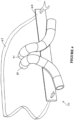
Figure 3 is a side view of the nasal cannula of the present invention in use by a patient, -
Figure 4 is a front perspective view of the nasal cannula of the present invention, -
Figure 5 is a back perspective view of the nasal cannula of the present invention, -
Figure 6 is a further back perspective view of the nasal cannula of the present invention, and -
Figure 7 is a side perspective view of an example of a nasal cannula. -
Figure 8 is a side view of nasal prongs showing hidden details and one embodiment of a cannula with pressure relief valve. -
Figure 9 is a cross-sectional side view of the pressure relief valve as shown inFigure 8 when in operation. - Whether used in a hospital environment or in a home environment, the nasal cannula of the present invention will generally have associated three main pieces of apparatus. Firstly an active humidifier that controls the temperature of a heater plate heating a body of water to achieve a desired temperature and humidity of the gases being humidified. Secondly a transport conduit from the humidifier to the patient is also required, which is preferably heated to reduce condensation, or "rain out". Thirdly a cannula designed to fit up into the nasal cavity and deliver humidified, pressurized gases.
- Referring to
Figure 1 a humidifying apparatus as might be used in a hospital generally referenced 1 is shown. The apparatus comprises abody 2 containing heating means comprising aheating plate 20 having an electric heating element therein or in thermal contact therewith and control means for example electronic circuitry which may include a microprocessor for controlling the supply of energy to the heating element. Thebody 2 is removably engageable with ahumidifying chamber 3 that contains water for humidifying gases. - Referring to
Figure 2 , which shows the humidifier apparatus in more detail, thehumidifying chamber 3 has edges, which engage withcollar 24 on the humidifier apparatus. The gases to be humidified may be a mixture of air, oxygen and anaesthetic for example, which are supplied to the chamber through gas inlet 4. This might be connected to a ventilator, source of pressurised oxygen, flow generator, or air compressor. Agases outlet 5 is also provided and thegases outlet 5 is connected to the conduit 6 (Figure 1 ), which conveys humidified gases to the patient at theend 7 of the conduit. Theend 7 of the conduit has a cannula (30, inFigure 3 ) connected to the patients nose so as to supply humidified gases to the user. Thehumidifier heater plate 20 has atemperature transducer 8 that is in electrical connection with the electronic control circuitry inbody 2 of the apparatus so that the control means monitors the temperature of the heating plate. - A
heating element 10 is provided within the conduit 6 to help prevent condensation of the humidified gases within the conduit. Such condensation is due to the temperature of the walls of the conduit being close to the ambient temperature, (being the temperature of the surrounding atmosphere) which is usually lower than the temperature of the humidified gases within the conduit. The heater element is effectively replaces the energy lost from the gases through conduction and convection during transit through the conduit. Thus the conduit heater element ensures the gases delivered are at an optimal temperature and humidity. - The
nasal cannula 30 of the present invention is shown in side view inFigure 3 when located within a patient'snares 31. One end of theinlet tube 32 is attached to end 7 of the conduit 6 (seeFigure 1 ) and accepts the gases flow from the pressurised source supplying gases and the humidifier. The other end of thetube 32 terminates at a y-connection where each of the arms of the Y aretubes inlet tube 32 andtubes - Referring to
Figures 3 to 6 , operatively attached to abody 44 are twonasal prongs inlet tube 32 that branches, at a y-connection, into twotubes nasal prongs prongs prongs body 44 are attached to the patient's face via a strap 43. The strap 43 is attached to the body by appropriate fastening means, for example, VELCRO™, which may be adjusted to suit the size of the patients head and ensures theprongs body 44 fits comfortably against the patient's face. - Referring to
Figures 5 and6 , theprongs Figure 3 ). - The
prongs Figure 3 , where arrow A shows the direction of inhaled gases and arrow B shows the direction of exhaled gases. - In the embodiment where the
prongs prongs - The entire assembly of the nasal cannula, including the cannula, body and prongs attaching the cannula to the patient's face and nares, are moulded from silicon or other flexible material as are known is the art for cannula construction.
- In an example of a nasal cannula, as shown in
Figure 7 , the inlet to thecannula 70 is provided through one tube. Here, gases flow from theinlet tube 71 through each of theprongs body section 74 that is shaped so it fits the contours of the patient's face.
The cannula and body is maintained against thepatients 30 face again by way of ahead strap 75. - The cannula of the present invention according to one embodiment comprises wide bore cannula to minimise the flow resistance and the entry velocity. For adults an approximate nare diameter of 6mm has been found to be suitable (actual diameter depends on cannula shape), this compares with 2-3mm in the prior art. This allows the present invention to deliver higher than 30 L/min of oxygen enriched gases, whereas prior art systems with small bore cannula can only deliver an absolute maximum of 6 L/min of dry gas or 20 L/min humidified gas, for the following reasons:
- a) Flows higher than 20L/min through existing cannula (i.e. VAPOTHERM™ system) are noisy due to the creation of turbulent gas flow.
- b) Existing cannula (i.e. VAPOTHERM™ system) have a high resistance to gas flow, requiring the use of a supply of gas exceeding 50cmH2O pressure.
- c) Flows higher than 20L/min through existing narrow bore cannula (i.e. VAPOTHERM™ system) create a jet of gas upon exiting the cannula that becomes irritating to the airway over short periods of time.
- The expiration of gases by the patient against the high incoming flow provides positive end expiratory pressure (PEEP). PEEP keeps the airways and alveoli from collapsing at end-expiration and can reopen airways and alveoli that have already collapsed. This improves gas exchange (decreased intra pulmonary shunt), reduces the resistance to airflow (lung resistance), and makes the lungs less stiff (increased lung compliance). Levels of oxygen and carbon dioxide may improve, reducing the need for supplemental oxygen and the sensation of breathlessness. PEEP may also improve cardiac performance by increasing mean intra thoracic pressure. PEEP is of special advantage to assisting in the treatment of obstructive lung diseases and heart failure, including emphysema, bronchiectasis, chronic bronchitis, cystic fibrosis and pulmonary edema.
- The wide bore cannula of the present invention also allows for the provision of gases to the patient that exceeds the patient's peak inspiratory flow. Consequently, a small amount of positive pressure is also generated during the inspiratory phase. This will create inspiratory positive airway pressure (IPAP) that, like PEEP, keeps airways and alveoli from collapsing and reduces the effort to inhale. IPAP is of special advantage to patients who experience breathlessness during respiratory failure.
- The ability of the cannula of the present invention to provide these forms of pressure support also allows the cannula to deliver pressure oscillations to the patient. Pressure oscillations are known to improve the clearance of sputum from the lungs and the exchange of respiratory gases between the blood and alveolar air.
- The cannula of the present invention does not create a seal against the nares, and so allow a continuous leakage of gas out of the nose between the cannula and nares. In the event of improper fitting causing the prongs to seal against the nares, one embodiment of the nasal cannula of the present invention is provided with a pressure relief valve. This valve will ensure barotrauma is not inflicted upon the patient. This pressure relief could be similar in form to a CPAP valve as is known in the art or could be constructed integrally within the moulding of the nasal cannula as shown in
Figure 8 . The continuous flow around the nares allowed by the device not sealing also eliminates the need for a bias flow outlet such as that incorporated in the NASAL-AIRE™ manufactured by Innomed Inc. - Referring now to
Figures 8 and 9 , one embodiment of nasal cannula withprongs 80 is shown (without additional head straps and the like) that has apressure relief valve 81. Thepressure relief valve 81 is a removable flap that is located against themanifold 82 of the cannula. Therelief valve 81 is preferably made from a soft flexible material, such as silicone. The manifold 82 has threerecesses protrusion 86 that forms part of therelief valve 81. Theprotrusion 86, being made of a soft flexible material can be pushed throughrecess 84, in order to locate thevalve 81 in the manifold. The shape of the protrusion is such that a large pulling force on thevalve 81 is required before theprotrusion 84 can be removed from the manifold 82. As the ends 87, 88 of theflap 81 are made from a supple material they are capable of being pushed outwards (as shown inFigure 9 ), when the cannula is in use and when excessive pressure exists in the manifold or prongs, to allow gases to be released through the side recesses 83, 85 on the manifold. - It must be appreciated that
Figures 8 and 9 merely show one embodiment of nasal cannula with a pressure relief valve. Other embodiments with pressure relief valves, for example, embodiments including pressure relief valves at the humidification means, humidified gases transport means or elsewhere on the nasal cannula are envisaged. - The cannula of the present invention does not require rebreathing of expired gases; rather the cannula reduces anatomical dead space by flushing the pharynx with fresh respiratory gases. Further, the nasal cannula of the present invention does not deliver continuous positive airway pressure, but instead delivers a form of bi-level positive airway pressure in which PEEP is greater than IPAP.
- A further consequence that is provided by the nasal cannula in allowing for the exceeding of peak inspiratory flow is that all gases the patient is breathing are being delivered from the cannula and do not contain any portion of room air as in the prior art. This allows the oxygen percentage in the patient's breath to be controlled over the full range (up to 100%) to be known. This has previously only been possible with a mask, which is much more claustrophobic and restrictive to the patient and severely hinders the patients' ability to talk or eat. The cannula, therefore, incorporates the advantages of Venturi mask, nasal cannula, and non-rebreathing mask as stated earlier without the disadvantages of discomfort (Venturi mask), inconsistent FiO2 (prior art nasal cannula), need for a tight seal between mask and patient (non-rebreathing mask), and possibility of rebreathing expired gases (non-rebreathing mask).
- Finally, in summary, the nasal cannula of the present invention allows for the delivery of humidified air (whether the air is blended with or without oxygen) to a patient at flows greater than 30 L/min that offers the following benefits over standard cannula.
- 1) High FiO2 (fraction of inspired oxygen), where normal cannula provide less than 32%.
- 2) Known FiO2 that is equivalent to a facemask.
- 3) PEEP (positive end expiratory pressure) caused by breathing out against the inward flow of gases.
- 4) IPAP (inspiratory positive airway pressure) where delivered flow is greater than the peak inspiratory flow.
- 5) Delivers pressure oscillations.
- 6) Reduces breathlessness.
Claims (11)
- A wide bore nasal cannula (30, 70) suitable for the delivery of high flow humidified pressurised oxygen and/or air, the nasal cannula comprising:an inlet tube (71) adapted to, in use, be in fluid communication with a pressurised source of gases,a pair of nasal prongs (40, 41; 72, 73) arranged in fluid communication with the inlet tube (71), the prongs adapted to, in use, communicate gases from the inlet to the nares of a patient,a body section (30, 70), the prongs (40, 41; 72, 73) attached to the body section (44, 74),a head strap (75), the body section (30, 70) and the prongs are maintained in use, against the patient's face by way of the headstrap (43, 75),wherein, the prongs are elliptical in shape and of a diameter such that exhaled gases can be breathed out by the patient past each of the prongs, the prongs being; when in continuous use by the patient, non-sealing with the nares of the patient,wherein the prongs are angled inwards toward the septum of the nose.
- The nasal cannula as claimed in claim 1, wherein the prongs (40, 41; 72, 73) have a diameter of about 6mm.
- The nasal cannula as claimed in claim 1 or 2, wherein the top of each of the prongs (40, 41; 72, 73) points toward the back of the patient's head.
- The nasal cannula as claimed in any one of claims 1-3, wherein the prongs (40, 41; 72, 73) and body section (44, 74) are moulded from a silicone material.
- The nasal cannula as claimed in any one of claims 1-4, wherein the prongs are adapted to, in use, allow delivery of oxygen enriched gases at a flow rate higher than about 30L/min.
- The nasal cannula as claimed in any one of claims 1-5, wherein the wide bore cannula is to minimise flow resistance and entry velocity.
- The nasal cannula as claimed in any one of claim 1-6, wherein the nasal prongs are angled inwards towards the septum of the nose and are curved towards the sagittal (midline) plane, to follow the nasal cavity towards the posterior and follow the inner shape of the patient's nostrils.
- The nasal cannula as claimed in any one of claims 1-7, wherein in use the prongs allow high flow delivery of humidified gases and create positive airway pressure in the patient's airway during inspiration and positive end expiratory pressure during expiration.
- The nasal cannula as claimed in any one of claims 1-8, wherein the prongs provide a high flow such that, in use, the pharynx is flushed and anatomical dead space is reduced.
- The nasal cannula as claimed in claim 1, wherein the prongs allow high flow delivery of humidified gases and create positive airway pressure in the patient's airway during inspiration and positive end expiratory pressure during expiration, and wherein the the top of each of the prongs (40, 41; 72, 73) points toward the back of the patient's head.
- A system for delivery of a humidified gas comprising air to a patient, the system comprising the nasal cannula as defined in any one of claims 1 to 10 and wherein a gas flow of greater than 30 L/min is capable of being directed to said nasal cannula for delivery to the patient.
Priority Applications (1)
| Application Number | Priority Date | Filing Date | Title |
|---|---|---|---|
| EP20171533.1A EP3738635A1 (en) | 2002-02-04 | 2003-02-03 | Breathing assistance apparatus |
Applications Claiming Priority (4)
| Application Number | Priority Date | Filing Date | Title |
|---|---|---|---|
| NZ51703102 | 2002-02-04 | ||
| EP03715867.2A EP1471962B1 (en) | 2002-02-04 | 2003-02-03 | Breathing assistance apparatus |
| PCT/NZ2003/000012 WO2003066145A1 (en) | 2002-02-04 | 2003-02-03 | Breathing assistance apparatus |
| EP14150364.9A EP2799103B1 (en) | 2002-02-04 | 2003-02-03 | Breathing assistance apparatus |
Related Parent Applications (3)
| Application Number | Title | Priority Date | Filing Date |
|---|---|---|---|
| EP03715867.2A Division EP1471962B1 (en) | 2002-02-04 | 2003-02-03 | Breathing assistance apparatus |
| EP14150364.9A Division-Into EP2799103B1 (en) | 2002-02-04 | 2003-02-03 | Breathing assistance apparatus |
| EP14150364.9A Division EP2799103B1 (en) | 2002-02-04 | 2003-02-03 | Breathing assistance apparatus |
Related Child Applications (2)
| Application Number | Title | Priority Date | Filing Date |
|---|---|---|---|
| EP20171533.1A Division-Into EP3738635A1 (en) | 2002-02-04 | 2003-02-03 | Breathing assistance apparatus |
| EP20171533.1A Division EP3738635A1 (en) | 2002-02-04 | 2003-02-03 | Breathing assistance apparatus |
Publications (3)
| Publication Number | Publication Date |
|---|---|
| EP3050589A1 EP3050589A1 (en) | 2016-08-03 |
| EP3050589B1 EP3050589B1 (en) | 2020-04-29 |
| EP3050589B2 true EP3050589B2 (en) | 2023-08-02 |
Family
ID=27731023
Family Applications (4)
| Application Number | Title | Priority Date | Filing Date |
|---|---|---|---|
| EP16151504.4A Expired - Lifetime EP3050589B2 (en) | 2002-02-04 | 2003-02-03 | Breathing assistance apparatus |
| EP03715867.2A Expired - Lifetime EP1471962B1 (en) | 2002-02-04 | 2003-02-03 | Breathing assistance apparatus |
| EP14150364.9A Expired - Lifetime EP2799103B1 (en) | 2002-02-04 | 2003-02-03 | Breathing assistance apparatus |
| EP20171533.1A Withdrawn EP3738635A1 (en) | 2002-02-04 | 2003-02-03 | Breathing assistance apparatus |
Family Applications After (3)
| Application Number | Title | Priority Date | Filing Date |
|---|---|---|---|
| EP03715867.2A Expired - Lifetime EP1471962B1 (en) | 2002-02-04 | 2003-02-03 | Breathing assistance apparatus |
| EP14150364.9A Expired - Lifetime EP2799103B1 (en) | 2002-02-04 | 2003-02-03 | Breathing assistance apparatus |
| EP20171533.1A Withdrawn EP3738635A1 (en) | 2002-02-04 | 2003-02-03 | Breathing assistance apparatus |
Country Status (7)
| Country | Link |
|---|---|
| US (1) | US20050178383A1 (en) |
| EP (4) | EP3050589B2 (en) |
| JP (1) | JP2005516692A (en) |
| AU (1) | AU2003219624B2 (en) |
| CA (1) | CA2474925A1 (en) |
| ES (1) | ES2568604T3 (en) |
| WO (1) | WO2003066145A1 (en) |
Families Citing this family (59)
| Publication number | Priority date | Publication date | Assignee | Title |
|---|---|---|---|---|
| US6776162B2 (en) | 2000-03-13 | 2004-08-17 | Innomed Technologies, Inc. | Ventilation interface for sleep apnea therapy |
| WO2001041854A2 (en) * | 1999-12-10 | 2001-06-14 | Vapotherm, Inc. | Apparatus and method for respiratory tract therapy |
| US7708013B2 (en) * | 2000-12-08 | 2010-05-04 | Vapotherm, Inc. | Apparatus and method for delivering water vapor to a gas |
| US7827981B2 (en) * | 2003-01-29 | 2010-11-09 | Vapotherm, Inc. | Method for reducing the work of breathing |
| US7493902B2 (en) | 2003-05-30 | 2009-02-24 | Fisher & Paykel Healthcare Limited | Breathing assistance apparatus |
| US6997187B2 (en) | 2003-09-10 | 2006-02-14 | Innomed Technologies, Inc. | Nasal interface and system including ventilation insert |
| US7000613B2 (en) | 2003-08-06 | 2006-02-21 | Innomed Technologies, Inc. | Nasal interface and system including ventilation insert |
| US7472707B2 (en) | 2003-08-06 | 2009-01-06 | Innomed Technologies, Inc. | Nasal interface and system including ventilation insert |
| FR2875138B1 (en) * | 2004-09-15 | 2008-07-11 | Mallinckrodt Dev France Sa | CONTROL METHOD FOR A HEATING HUMIDIFIER |
| JP4993862B2 (en) * | 2005-02-15 | 2012-08-08 | 株式会社メトラン | Respiratory device |
| US20060266359A1 (en) * | 2005-02-28 | 2006-11-30 | Van Beurden Jason P | Pressure relief valve |
| US8028697B2 (en) | 2005-04-28 | 2011-10-04 | Trudell Medical International | Ventilator circuit and method for the use thereof |
| CN101212997B (en) | 2005-07-01 | 2012-09-05 | 菲舍尔和佩克尔保健有限公司 | A breathing assistance apparatus |
| DE102006034028A1 (en) * | 2005-08-01 | 2007-02-08 | Weinmann Geräte für Medizin GmbH + Co. KG | Artificial respiration e.g. CPAP respiration, apparatus for use in clinic, has respired air humidifier comprising upper part not separable from lower part, and air outlet disposed at preset angle with respect to air inlet |
| DE202006020951U1 (en) | 2005-08-15 | 2011-02-24 | ResMed Ltd., Bella Vista | Humidifier and / or flow generator for CPAP device |
| US11717174B2 (en) | 2005-09-12 | 2023-08-08 | ResMed Pty Ltd | High flow therapy device utilizing a non-sealing respiratory interface and related methods |
| US11458270B2 (en) | 2005-09-12 | 2022-10-04 | ResMed Pty Ltd | High flow therapy device utilizing a non-sealing respiratory interface and related methods |
| US8522782B2 (en) * | 2005-09-12 | 2013-09-03 | Mergenet Medical, Inc. | High flow therapy device utilizing a non-sealing respiratory interface and related methods |
| US11833301B2 (en) | 2005-09-12 | 2023-12-05 | ResMed Pty Ltd | High flow therapy device utilizing a non-sealing respiratory interface and related methods |
| US11696992B2 (en) | 2005-09-12 | 2023-07-11 | ResMed Pty Ltd | High flow therapy device utilizing a non-sealing respiratory interface and related methods |
| US11497407B2 (en) | 2005-09-12 | 2022-11-15 | ResMed Pty Ltd | High flow therapy device utilizing a non-sealing respiratory interface and related methods |
| US7677246B2 (en) * | 2005-09-23 | 2010-03-16 | Ric Investments, Llc | Modular pressure support system |
| CA2622734A1 (en) * | 2005-12-14 | 2007-06-14 | Mergenet Medical, Inc. | High flow therapy device utilizing a non-sealing respiratory interface and related methods |
| US11318267B2 (en) | 2006-09-12 | 2022-05-03 | ResMed Pty Ltd | High flow therapy device utilizing a non-sealing respiratory interface and related methods |
| US20080279540A1 (en) * | 2007-05-11 | 2008-11-13 | Chao-Chih Huang | Air delivery pipe of a humidifying apparatus |
| US8365726B2 (en) | 2007-06-07 | 2013-02-05 | Resmed Limited | Tub for humidifier |
| DE102007033404B3 (en) * | 2007-07-18 | 2008-06-12 | Dräger Medical AG & Co. KG | Supply device for respiratory gas has a respiratory gas module with inlet and outlet channels as well as valves, a blower module and a plug-in coupling device |
| US8356593B2 (en) | 2007-07-18 | 2013-01-22 | Vapotherm, Inc. | Delivery tube for breathing gas heating and humidification system |
| US8905023B2 (en) | 2007-10-05 | 2014-12-09 | Vapotherm, Inc. | Hyperthermic humidification system |
| DK2265309T3 (en) * | 2008-03-17 | 2016-03-29 | Discovery Lab Inc | FAN EXCEEDED RACE ADAPTER AND proximal AEROSOLFORSYNINGSSYSTEM |
| EP3075406A1 (en) | 2008-04-30 | 2016-10-05 | ResMed R&D Germany GmbH | Apparatus and method for controlled delivery of a breathing gas to the respiratory tracts of a user |
| NZ727179A (en) | 2008-06-05 | 2018-06-29 | Resmed Ltd | Treatment of respiratory conditions |
| EP2179760B1 (en) | 2008-10-22 | 2013-02-27 | Trudell Medical International | Modular Aerosol Delivery System |
| AU2015203493B2 (en) * | 2008-12-01 | 2017-08-17 | Fisher & Paykel Healthcare Limited | Nasal cannula |
| US20100242961A1 (en) * | 2009-03-31 | 2010-09-30 | Nellcor Puritan Bennett Llc | Systems and methods for preventing water damage in a breathing assistance system |
| US20100313898A1 (en) * | 2009-05-15 | 2010-12-16 | Richard Ronald F | Apparatus and methods for treating sleep related disorders |
| US20100300446A1 (en) * | 2009-05-26 | 2010-12-02 | Nellcor Puritan Bennett Llc | Systems and methods for protecting components of a breathing assistance system |
| JP5997698B2 (en) | 2010-10-18 | 2016-09-28 | フィッシャー アンド ペイケル ヘルスケア リミテッド | Nasal cannula, conduit and fixation system |
| TWI687244B (en) * | 2011-04-08 | 2020-03-11 | 紐西蘭商費雪&佩凱爾關心健康有限公司 | A nasal cannula, conduit and securement system |
| EP2968821B8 (en) | 2013-03-15 | 2021-11-24 | Fisher & Paykel Healthcare Limited | Nasal cannula assemblies and related parts |
| EP4035714A1 (en) | 2013-08-09 | 2022-08-03 | Fisher & Paykel Healthcare Limited | Asymmetrical nasal delivery elements and fittings for nasal interfaces |
| EP3030302B1 (en) * | 2013-09-04 | 2023-02-22 | Fisher&Paykel Healthcare Limited | Improvements to flow therapy |
| JP2016049132A (en) * | 2014-08-28 | 2016-04-11 | アトムメディカル株式会社 | Cannula apparatus |
| US10596345B2 (en) | 2014-12-31 | 2020-03-24 | Vapotherm, Inc. | Systems and methods for humidity control |
| JP6843759B2 (en) | 2015-03-31 | 2021-03-17 | フィッシャー アンド ペイケル ヘルスケア リミテッド | User interface and system for supplying gas to the airways |
| US10398871B2 (en) | 2015-03-31 | 2019-09-03 | Vapotherm, Inc. | Systems and methods for patient-proximate vapor transfer for respiratory therapy |
| KR102605278B1 (en) | 2015-03-31 | 2023-11-23 | 피셔 앤 페이켈 핼스케어 리미티드 | Method and device for oxygen supply and/or CO2 removal |
| US10441736B2 (en) | 2015-04-24 | 2019-10-15 | Fisher & Paykel Healthcare Limited | Respiratory mask with cheek supports |
| CN109803707B (en) | 2016-08-11 | 2022-03-22 | 费雪派克医疗保健有限公司 | Collapsible catheter, patient interface and headgear connector |
| USD870269S1 (en) | 2016-09-14 | 2019-12-17 | Fisher & Paykel Healthcare Limited | Nasal cannula assembly |
| EP3525861B1 (en) | 2016-10-14 | 2022-03-30 | Vapotherm, Inc. | System for high velocity nasal insufflation |
| WO2018127591A1 (en) * | 2017-01-06 | 2018-07-12 | INSERM (Institut National de la Santé et de la Recherche Médicale) | Jet aerosol dispenser |
| CN110740774B (en) * | 2017-06-13 | 2023-03-17 | 马奎特紧急护理公司 | Nasal patient interface device, breathing apparatus and method for operating a breathing apparatus |
| USD849243S1 (en) | 2017-11-21 | 2019-05-21 | Fisher & Paykel Healthcare Limited | Nasal cannula |
| USD849242S1 (en) | 2017-11-21 | 2019-05-21 | Fisher & Paykel Healthcare Limited | Nasal cannula assembly |
| USD878549S1 (en) | 2017-11-21 | 2020-03-17 | Fisher & Paykel Healthcare Limited | Connector for nasal cannula assembly |
| USD848614S1 (en) | 2017-11-21 | 2019-05-14 | Fisher & Paykel Healthcare Limited | Pad for nasal cannula assembly |
| US11247016B2 (en) | 2018-05-14 | 2022-02-15 | Covidien Lp | Systems and methods for ventilation humidification |
| EP3821932A1 (en) * | 2019-11-17 | 2021-05-19 | Oxypoint NV | Linking element for linking a hose barb component |
Family Cites Families (35)
| Publication number | Priority date | Publication date | Assignee | Title |
|---|---|---|---|---|
| DE28036C (en) * | 1884-02-12 | 1884-07-23 | J. WOLFF in Grofs-Gerau, Gr. Hessen | Outdoor breathers |
| US2868199A (en) * | 1955-05-20 | 1959-01-13 | Charles H Hudson | Cannula |
| US2931358A (en) * | 1958-07-30 | 1960-04-05 | David S Sheridan | Nasal cannulae |
| US3513844A (en) | 1968-04-30 | 1970-05-26 | Metro Hospital Supply Co Inc | Adjustable nonrestrictive nasal cannula |
| US3566862A (en) * | 1968-08-01 | 1971-03-02 | Paul A Schuh | Respiration apparatus |
| US3682171A (en) | 1971-03-31 | 1972-08-08 | Baxter Laboratories Inc | Nasal cannula |
| US3726275A (en) | 1971-12-14 | 1973-04-10 | I Jackson | Nasal cannulae |
| US3807445A (en) * | 1972-06-19 | 1974-04-30 | American Hospital Supply Corp | Audible pressure relief valve for medical humidifier |
| US4106505A (en) * | 1977-01-17 | 1978-08-15 | Salter Labs., Inc. | Nasal cannula assembly |
| US4156426A (en) | 1977-08-11 | 1979-05-29 | Gold Lawrence W | Head-mounted oxygen-administration device |
| US4790308A (en) * | 1984-04-04 | 1988-12-13 | Sherwood Medical Company | Nasal cannula harness |
| EP0197114A1 (en) * | 1984-10-09 | 1986-10-15 | Oxygen Enrichment Company, Ltd. | Method and apparatus for the treatment of the respiratory tract |
| GB2173274B (en) * | 1985-04-04 | 1989-02-01 | Boc Group Plc | Improvements in inhalation apparatus |
| US4808160A (en) * | 1986-04-14 | 1989-02-28 | Timmons John W | Nasal cannula apparatus |
| US4753233A (en) | 1987-02-10 | 1988-06-28 | Advantage Medical | Nasal cannula |
| FR2638361B1 (en) * | 1988-10-28 | 1991-01-11 | Diffusion Tech Francaise Sarl | NARINARY MOUTHPIECE ADAPTABLE TO ALL MEDICAL APPLIANCES OF THE NEBULIZER TYPE AND OTHER |
| US4996983A (en) * | 1989-01-31 | 1991-03-05 | Amrhein Floyd E | Inhaler filtration device with housing supportable by spectacle temple |
| WO1992020392A1 (en) * | 1991-05-24 | 1992-11-26 | Calor Air Separation Limited | Nasal cannula |
| EP0535952B1 (en) * | 1991-10-04 | 1997-12-29 | FISHER & PAYKEL LIMITED | Humidifier |
| US5687715A (en) * | 1991-10-29 | 1997-11-18 | Airways Ltd Inc | Nasal positive airway pressure apparatus and method |
| US5495848A (en) * | 1994-11-25 | 1996-03-05 | Nellcar Puritan Bennett | Monitoring system for delivery of therapeutic gas |
| DE19515739C2 (en) * | 1995-05-03 | 1997-09-11 | Holger Krohn | Method and device for generating health-friendly breathing air in nasal positive pressure respirators |
| EP0873148A4 (en) * | 1995-11-13 | 1999-12-29 | Fisher & Paykel | Heated respiratory conduit |
| US5682881A (en) | 1996-10-21 | 1997-11-04 | Winthrop; Neil | Nasal CPAP/Cannula and securement apparatus |
| CA2222830C (en) * | 1996-12-02 | 2004-03-30 | Fisher & Paykel Limited | Humidifier sleep apnea treatment apparatus |
| AUPO742297A0 (en) * | 1997-06-18 | 1997-07-10 | Resmed Limited | An apparatus for supplying breathable gas |
| EP1198266A1 (en) | 1999-05-28 | 2002-04-24 | Euromedico Ltd. | Gas-supplying device |
| US6435180B1 (en) * | 1999-07-01 | 2002-08-20 | J&M Distributors Limited | Method and apparatus for delivering humidified air to a face mask |
| WO2001041854A2 (en) | 1999-12-10 | 2001-06-14 | Vapotherm, Inc. | Apparatus and method for respiratory tract therapy |
| AUPQ821500A0 (en) * | 2000-06-19 | 2000-07-13 | Australian Centre For Advanced Medical Technology Ltd | Mask |
| US6668828B1 (en) * | 2000-10-16 | 2003-12-30 | Pulmonox Technologies Corporations | System and elements for managing therapeutic gas administration to a spontaneously breathing non-ventilated patient |
| DE10105383C2 (en) | 2001-02-06 | 2003-06-05 | Heptec Gmbh | Anti-snoring device |
| US6684883B1 (en) * | 2001-08-21 | 2004-02-03 | Bonnie C. Burns | Nasal cannula headband apparatus |
| US6679265B2 (en) * | 2001-10-25 | 2004-01-20 | Worldwide Medical Technologies | Nasal cannula |
| US20050121037A1 (en) * | 2003-08-08 | 2005-06-09 | Wood Thomas J. | Nasal ventilation interface |
-
2003
- 2003-02-03 EP EP16151504.4A patent/EP3050589B2/en not_active Expired - Lifetime
- 2003-02-03 CA CA002474925A patent/CA2474925A1/en not_active Abandoned
- 2003-02-03 JP JP2003565566A patent/JP2005516692A/en active Pending
- 2003-02-03 EP EP03715867.2A patent/EP1471962B1/en not_active Expired - Lifetime
- 2003-02-03 US US10/503,482 patent/US20050178383A1/en not_active Abandoned
- 2003-02-03 AU AU2003219624A patent/AU2003219624B2/en not_active Expired
- 2003-02-03 ES ES14150364.9T patent/ES2568604T3/en not_active Expired - Lifetime
- 2003-02-03 WO PCT/NZ2003/000012 patent/WO2003066145A1/en active Application Filing
- 2003-02-03 EP EP14150364.9A patent/EP2799103B1/en not_active Expired - Lifetime
- 2003-02-03 EP EP20171533.1A patent/EP3738635A1/en not_active Withdrawn
Also Published As
| Publication number | Publication date |
|---|---|
| ES2568604T3 (en) | 2016-05-03 |
| EP1471962A4 (en) | 2010-11-10 |
| EP2799103B1 (en) | 2016-04-13 |
| EP1471962B1 (en) | 2014-03-12 |
| EP3050589B1 (en) | 2020-04-29 |
| US20050178383A1 (en) | 2005-08-18 |
| AU2003219624B2 (en) | 2006-11-30 |
| JP2005516692A (en) | 2005-06-09 |
| AU2003219624A1 (en) | 2003-09-02 |
| EP3050589A1 (en) | 2016-08-03 |
| EP2799103A1 (en) | 2014-11-05 |
| EP3738635A1 (en) | 2020-11-18 |
| EP1471962A1 (en) | 2004-11-03 |
| WO2003066145A1 (en) | 2003-08-14 |
| CA2474925A1 (en) | 2003-08-14 |
Similar Documents
| Publication | Publication Date | Title |
|---|---|---|
| EP3050589B2 (en) | Breathing assistance apparatus | |
| AU2020201601B2 (en) | An interface | |
| US10220175B2 (en) | Breathing assistance apparatus | |
| EP2326376B1 (en) | Devices for providing mechanical ventilation with an open airway interface | |
| EP1275412B1 (en) | Exhalation valve for a nasal breathing mask | |
| EP1438086A2 (en) | Nasal cannula | |
| AU2019237360A1 (en) | System and method for non-invasive ventilation |
Legal Events
| Date | Code | Title | Description |
|---|---|---|---|
| PUAI | Public reference made under article 153(3) epc to a published international application that has entered the european phase |
Free format text: ORIGINAL CODE: 0009012 |
|
| AC | Divisional application: reference to earlier application |
Ref document number: 1471962 Country of ref document: EP Kind code of ref document: P Ref document number: 2799103 Country of ref document: EP Kind code of ref document: P |
|
| AK | Designated contracting states |
Kind code of ref document: A1 Designated state(s): AT BE BG CH CY CZ DE DK EE ES FI FR GB GR HU IE IT LI LU MC NL PT SE SI SK TR |
|
| RIN1 | Information on inventor provided before grant (corrected) |
Inventor name: WHITE, CRAIG KARL Inventor name: FOREMAN, MARK Inventor name: MACKIE, SCOTT ROBERT |
|
| STAA | Information on the status of an ep patent application or granted ep patent |
Free format text: STATUS: REQUEST FOR EXAMINATION WAS MADE |
|
| 17P | Request for examination filed |
Effective date: 20170201 |
|
| RBV | Designated contracting states (corrected) |
Designated state(s): AT BE BG CH CY CZ DE DK EE ES FI FR GB GR HU IE IT LI LU MC NL PT SE SI SK TR |
|
| GRAP | Despatch of communication of intention to grant a patent |
Free format text: ORIGINAL CODE: EPIDOSNIGR1 |
|
| STAA | Information on the status of an ep patent application or granted ep patent |
Free format text: STATUS: GRANT OF PATENT IS INTENDED |
|
| INTG | Intention to grant announced |
Effective date: 20190523 |
|
| GRAJ | Information related to disapproval of communication of intention to grant by the applicant or resumption of examination proceedings by the epo deleted |
Free format text: ORIGINAL CODE: EPIDOSDIGR1 |
|
| STAA | Information on the status of an ep patent application or granted ep patent |
Free format text: STATUS: REQUEST FOR EXAMINATION WAS MADE |
|
| INTC | Intention to grant announced (deleted) | ||
| GRAP | Despatch of communication of intention to grant a patent |
Free format text: ORIGINAL CODE: EPIDOSNIGR1 |
|
| STAA | Information on the status of an ep patent application or granted ep patent |
Free format text: STATUS: GRANT OF PATENT IS INTENDED |
|
| INTG | Intention to grant announced |
Effective date: 20191122 |
|
| GRAS | Grant fee paid |
Free format text: ORIGINAL CODE: EPIDOSNIGR3 |
|
| GRAA | (expected) grant |
Free format text: ORIGINAL CODE: 0009210 |
|
| STAA | Information on the status of an ep patent application or granted ep patent |
Free format text: STATUS: THE PATENT HAS BEEN GRANTED |
|
| AC | Divisional application: reference to earlier application |
Ref document number: 1471962 Country of ref document: EP Kind code of ref document: P Ref document number: 2799103 Country of ref document: EP Kind code of ref document: P |
|
| AK | Designated contracting states |
Kind code of ref document: B1 Designated state(s): AT BE BG CH CY CZ DE DK EE ES FI FR GB GR HU IE IT LI LU MC NL PT SE SI SK TR |
|
| REG | Reference to a national code |
Ref country code: GB Ref legal event code: FG4D |
|
| REG | Reference to a national code |
Ref country code: CH Ref legal event code: EP |
|
| REG | Reference to a national code |
Ref country code: AT Ref legal event code: REF Ref document number: 1262364 Country of ref document: AT Kind code of ref document: T Effective date: 20200515 |
|
| REG | Reference to a national code |
Ref country code: DE Ref legal event code: R096 Ref document number: 60352465 Country of ref document: DE |
|
| REG | Reference to a national code |
Ref country code: IE Ref legal event code: FG4D |
|
| REG | Reference to a national code |
Ref country code: NL Ref legal event code: MP Effective date: 20200429 |
|
| PG25 | Lapsed in a contracting state [announced via postgrant information from national office to epo] |
Ref country code: GR Free format text: LAPSE BECAUSE OF FAILURE TO SUBMIT A TRANSLATION OF THE DESCRIPTION OR TO PAY THE FEE WITHIN THE PRESCRIBED TIME-LIMIT Effective date: 20200730 Ref country code: PT Free format text: LAPSE BECAUSE OF FAILURE TO SUBMIT A TRANSLATION OF THE DESCRIPTION OR TO PAY THE FEE WITHIN THE PRESCRIBED TIME-LIMIT Effective date: 20200831 Ref country code: SE Free format text: LAPSE BECAUSE OF FAILURE TO SUBMIT A TRANSLATION OF THE DESCRIPTION OR TO PAY THE FEE WITHIN THE PRESCRIBED TIME-LIMIT Effective date: 20200429 Ref country code: FI Free format text: LAPSE BECAUSE OF FAILURE TO SUBMIT A TRANSLATION OF THE DESCRIPTION OR TO PAY THE FEE WITHIN THE PRESCRIBED TIME-LIMIT Effective date: 20200429 |
|
| REG | Reference to a national code |
Ref country code: AT Ref legal event code: MK05 Ref document number: 1262364 Country of ref document: AT Kind code of ref document: T Effective date: 20200429 |
|
| PG25 | Lapsed in a contracting state [announced via postgrant information from national office to epo] |
Ref country code: BG Free format text: LAPSE BECAUSE OF FAILURE TO SUBMIT A TRANSLATION OF THE DESCRIPTION OR TO PAY THE FEE WITHIN THE PRESCRIBED TIME-LIMIT Effective date: 20200729 |
|
| PG25 | Lapsed in a contracting state [announced via postgrant information from national office to epo] |
Ref country code: NL Free format text: LAPSE BECAUSE OF FAILURE TO SUBMIT A TRANSLATION OF THE DESCRIPTION OR TO PAY THE FEE WITHIN THE PRESCRIBED TIME-LIMIT Effective date: 20200429 |
|
| PG25 | Lapsed in a contracting state [announced via postgrant information from national office to epo] |
Ref country code: CZ Free format text: LAPSE BECAUSE OF FAILURE TO SUBMIT A TRANSLATION OF THE DESCRIPTION OR TO PAY THE FEE WITHIN THE PRESCRIBED TIME-LIMIT Effective date: 20200429 Ref country code: EE Free format text: LAPSE BECAUSE OF FAILURE TO SUBMIT A TRANSLATION OF THE DESCRIPTION OR TO PAY THE FEE WITHIN THE PRESCRIBED TIME-LIMIT Effective date: 20200429 Ref country code: AT Free format text: LAPSE BECAUSE OF FAILURE TO SUBMIT A TRANSLATION OF THE DESCRIPTION OR TO PAY THE FEE WITHIN THE PRESCRIBED TIME-LIMIT Effective date: 20200429 Ref country code: DK Free format text: LAPSE BECAUSE OF FAILURE TO SUBMIT A TRANSLATION OF THE DESCRIPTION OR TO PAY THE FEE WITHIN THE PRESCRIBED TIME-LIMIT Effective date: 20200429 Ref country code: ES Free format text: LAPSE BECAUSE OF FAILURE TO SUBMIT A TRANSLATION OF THE DESCRIPTION OR TO PAY THE FEE WITHIN THE PRESCRIBED TIME-LIMIT Effective date: 20200429 |
|
| REG | Reference to a national code |
Ref country code: DE Ref legal event code: R026 Ref document number: 60352465 Country of ref document: DE |
|
| PLBI | Opposition filed |
Free format text: ORIGINAL CODE: 0009260 |
|
| PLAX | Notice of opposition and request to file observation + time limit sent |
Free format text: ORIGINAL CODE: EPIDOSNOBS2 |
|
| PG25 | Lapsed in a contracting state [announced via postgrant information from national office to epo] |
Ref country code: SK Free format text: LAPSE BECAUSE OF FAILURE TO SUBMIT A TRANSLATION OF THE DESCRIPTION OR TO PAY THE FEE WITHIN THE PRESCRIBED TIME-LIMIT Effective date: 20200429 |
|
| 26 | Opposition filed |
Opponent name: RESMED PTY LTD. Effective date: 20210129 |
|
| PG25 | Lapsed in a contracting state [announced via postgrant information from national office to epo] |
Ref country code: SI Free format text: LAPSE BECAUSE OF FAILURE TO SUBMIT A TRANSLATION OF THE DESCRIPTION OR TO PAY THE FEE WITHIN THE PRESCRIBED TIME-LIMIT Effective date: 20200429 |
|
| PLBB | Reply of patent proprietor to notice(s) of opposition received |
Free format text: ORIGINAL CODE: EPIDOSNOBS3 |
|
| PG25 | Lapsed in a contracting state [announced via postgrant information from national office to epo] |
Ref country code: MC Free format text: LAPSE BECAUSE OF FAILURE TO SUBMIT A TRANSLATION OF THE DESCRIPTION OR TO PAY THE FEE WITHIN THE PRESCRIBED TIME-LIMIT Effective date: 20200429 |
|
| REG | Reference to a national code |
Ref country code: BE Ref legal event code: MM Effective date: 20210228 |
|
| PG25 | Lapsed in a contracting state [announced via postgrant information from national office to epo] |
Ref country code: LU Free format text: LAPSE BECAUSE OF NON-PAYMENT OF DUE FEES Effective date: 20210203 Ref country code: LI Free format text: LAPSE BECAUSE OF NON-PAYMENT OF DUE FEES Effective date: 20210228 Ref country code: CH Free format text: LAPSE BECAUSE OF NON-PAYMENT OF DUE FEES Effective date: 20210228 |
|
| PG25 | Lapsed in a contracting state [announced via postgrant information from national office to epo] |
Ref country code: IE Free format text: LAPSE BECAUSE OF NON-PAYMENT OF DUE FEES Effective date: 20210203 |
|
| PGFP | Annual fee paid to national office [announced via postgrant information from national office to epo] |
Ref country code: GB Payment date: 20220119 Year of fee payment: 20 Ref country code: DE Payment date: 20220119 Year of fee payment: 20 |
|
| PGFP | Annual fee paid to national office [announced via postgrant information from national office to epo] |
Ref country code: TR Payment date: 20220120 Year of fee payment: 20 Ref country code: IT Payment date: 20220119 Year of fee payment: 20 Ref country code: FR Payment date: 20220120 Year of fee payment: 20 |
|
| PG25 | Lapsed in a contracting state [announced via postgrant information from national office to epo] |
Ref country code: BE Free format text: LAPSE BECAUSE OF NON-PAYMENT OF DUE FEES Effective date: 20210228 |
|
| REG | Reference to a national code |
Ref country code: DE Ref legal event code: R071 Ref document number: 60352465 Country of ref document: DE |
|
| REG | Reference to a national code |
Ref country code: GB Ref legal event code: PE20 Expiry date: 20230202 |
|
| PG25 | Lapsed in a contracting state [announced via postgrant information from national office to epo] |
Ref country code: HU Free format text: LAPSE BECAUSE OF FAILURE TO SUBMIT A TRANSLATION OF THE DESCRIPTION OR TO PAY THE FEE WITHIN THE PRESCRIBED TIME-LIMIT; INVALID AB INITIO Effective date: 20030203 Ref country code: GB Free format text: LAPSE BECAUSE OF EXPIRATION OF PROTECTION Effective date: 20230202 |
|
| PG25 | Lapsed in a contracting state [announced via postgrant information from national office to epo] |
Ref country code: CY Free format text: LAPSE BECAUSE OF FAILURE TO SUBMIT A TRANSLATION OF THE DESCRIPTION OR TO PAY THE FEE WITHIN THE PRESCRIBED TIME-LIMIT Effective date: 20200429 |
|
| PUAH | Patent maintained in amended form |
Free format text: ORIGINAL CODE: 0009272 |
|
| STAA | Information on the status of an ep patent application or granted ep patent |
Free format text: STATUS: PATENT MAINTAINED AS AMENDED |
|
| REG | Reference to a national code |
Ref country code: CH Ref legal event code: PK Free format text: BERICHTIGUNGEN |
|
| 27A | Patent maintained in amended form |
Effective date: 20230802 |
|
| AK | Designated contracting states |
Kind code of ref document: B2 Designated state(s): AT BE BG CH CY CZ DE DK EE ES FI FR GB GR HU IE IT LI LU MC NL PT SE SI SK TR |
|
| RAP4 | Party data changed (patent owner data changed or rights of a patent transferred) |
Owner name: FISHER & PAYKEL HEALTHCARE LIMITED |
|
| REG | Reference to a national code |
Ref country code: DE Ref legal event code: R102 Ref document number: 60352465 Country of ref document: DE |
|
| RIN2 | Information on inventor provided after grant (corrected) |
Inventor name: FOREMAN, MARK Inventor name: WHITE, CRAIG KARL Inventor name: MACKIE, SCOTT ROBERT |