EP3050376B1 - Sélection de canal prenant en charge ibe - Google Patents
Sélection de canal prenant en charge ibe Download PDFInfo
- Publication number
- EP3050376B1 EP3050376B1 EP14783954.2A EP14783954A EP3050376B1 EP 3050376 B1 EP3050376 B1 EP 3050376B1 EP 14783954 A EP14783954 A EP 14783954A EP 3050376 B1 EP3050376 B1 EP 3050376B1
- Authority
- EP
- European Patent Office
- Prior art keywords
- transmitter
- subchannels
- subchannel
- neighboring
- transmitting
- Prior art date
- Legal status (The legal status is an assumption and is not a legal conclusion. Google has not performed a legal analysis and makes no representation as to the accuracy of the status listed.)
- Active
Links
- 230000005540 biological transmission Effects 0.000 claims description 50
- 238000000034 method Methods 0.000 claims description 30
- 238000004891 communication Methods 0.000 claims description 25
- 238000012545 processing Methods 0.000 description 29
- 238000010586 diagram Methods 0.000 description 23
- 230000006870 function Effects 0.000 description 17
- 238000005516 engineering process Methods 0.000 description 10
- 230000008569 process Effects 0.000 description 6
- 238000013461 design Methods 0.000 description 5
- 238000007726 management method Methods 0.000 description 5
- 230000011664 signaling Effects 0.000 description 5
- 230000006835 compression Effects 0.000 description 4
- 238000007906 compression Methods 0.000 description 4
- 238000001228 spectrum Methods 0.000 description 4
- 230000001413 cellular effect Effects 0.000 description 3
- 125000004122 cyclic group Chemical group 0.000 description 3
- 230000011218 segmentation Effects 0.000 description 3
- 230000006837 decompression Effects 0.000 description 2
- 238000001514 detection method Methods 0.000 description 2
- 230000003287 optical effect Effects 0.000 description 2
- 230000008520 organization Effects 0.000 description 2
- 230000010363 phase shift Effects 0.000 description 2
- 238000013468 resource allocation Methods 0.000 description 2
- 238000013459 approach Methods 0.000 description 1
- 238000003491 array Methods 0.000 description 1
- 230000010267 cellular communication Effects 0.000 description 1
- 238000012937 correction Methods 0.000 description 1
- 239000000284 extract Substances 0.000 description 1
- 230000002349 favourable effect Effects 0.000 description 1
- 230000000977 initiatory effect Effects 0.000 description 1
- 230000007774 longterm Effects 0.000 description 1
- 238000013507 mapping Methods 0.000 description 1
- 238000005259 measurement Methods 0.000 description 1
- 238000010295 mobile communication Methods 0.000 description 1
- 238000012986 modification Methods 0.000 description 1
- 230000004048 modification Effects 0.000 description 1
- 230000002093 peripheral effect Effects 0.000 description 1
- 230000003595 spectral effect Effects 0.000 description 1
- 230000001360 synchronised effect Effects 0.000 description 1
- 238000000411 transmission spectrum Methods 0.000 description 1
- 238000012384 transportation and delivery Methods 0.000 description 1
Images


Classifications
-
- H—ELECTRICITY
- H04—ELECTRIC COMMUNICATION TECHNIQUE
- H04L—TRANSMISSION OF DIGITAL INFORMATION, e.g. TELEGRAPHIC COMMUNICATION
- H04L5/00—Arrangements affording multiple use of the transmission path
- H04L5/003—Arrangements for allocating sub-channels of the transmission path
- H04L5/0058—Allocation criteria
- H04L5/0066—Requirements on out-of-channel emissions
-
- H—ELECTRICITY
- H04—ELECTRIC COMMUNICATION TECHNIQUE
- H04W—WIRELESS COMMUNICATION NETWORKS
- H04W52/00—Power management, e.g. TPC [Transmission Power Control], power saving or power classes
- H04W52/04—TPC
- H04W52/18—TPC being performed according to specific parameters
- H04W52/24—TPC being performed according to specific parameters using SIR [Signal to Interference Ratio] or other wireless path parameters
- H04W52/242—TPC being performed according to specific parameters using SIR [Signal to Interference Ratio] or other wireless path parameters taking into account path loss
-
- H—ELECTRICITY
- H04—ELECTRIC COMMUNICATION TECHNIQUE
- H04W—WIRELESS COMMUNICATION NETWORKS
- H04W52/00—Power management, e.g. TPC [Transmission Power Control], power saving or power classes
- H04W52/04—TPC
- H04W52/30—TPC using constraints in the total amount of available transmission power
- H04W52/34—TPC management, i.e. sharing limited amount of power among users or channels or data types, e.g. cell loading
- H04W52/346—TPC management, i.e. sharing limited amount of power among users or channels or data types, e.g. cell loading distributing total power among users or channels
-
- H—ELECTRICITY
- H04—ELECTRIC COMMUNICATION TECHNIQUE
- H04W—WIRELESS COMMUNICATION NETWORKS
- H04W52/00—Power management, e.g. TPC [Transmission Power Control], power saving or power classes
- H04W52/04—TPC
- H04W52/38—TPC being performed in particular situations
-
- H—ELECTRICITY
- H04—ELECTRIC COMMUNICATION TECHNIQUE
- H04W—WIRELESS COMMUNICATION NETWORKS
- H04W52/00—Power management, e.g. TPC [Transmission Power Control], power saving or power classes
- H04W52/04—TPC
- H04W52/38—TPC being performed in particular situations
- H04W52/42—TPC being performed in particular situations in systems with time, space, frequency or polarisation diversity
-
- H—ELECTRICITY
- H04—ELECTRIC COMMUNICATION TECHNIQUE
- H04W—WIRELESS COMMUNICATION NETWORKS
- H04W72/00—Local resource management
- H04W72/02—Selection of wireless resources by user or terminal
-
- H—ELECTRICITY
- H04—ELECTRIC COMMUNICATION TECHNIQUE
- H04W—WIRELESS COMMUNICATION NETWORKS
- H04W72/00—Local resource management
- H04W72/50—Allocation or scheduling criteria for wireless resources
- H04W72/54—Allocation or scheduling criteria for wireless resources based on quality criteria
- H04W72/541—Allocation or scheduling criteria for wireless resources based on quality criteria using the level of interference
Definitions
- the present disclosure relates generally to communication systems, and more particularly, to selecting one of a number of subchannels in a bandwidth for transmitting a signal while aware of an in-band emission (IBE) power of transmitters transmitting on the subchannels.
- IBE in-band emission
- Wireless communication systems are widely deployed to provide various telecommunication services such as telephony, video, data, messaging, and broadcasts.
- Typical wireless communication systems may employ multiple-access technologies capable of supporting communication with multiple users by sharing available system resources (e.g., bandwidth, transmit power).
- multiple-access technologies include code division multiple access (CDMA) systems, time division multiple access (TDMA) systems, frequency division multiple access (FDMA) systems, orthogonal frequency division multiple access (OFDMA) systems, single-carrier frequency division multiple access (SC-FDMA) systems, and time division synchronous code division multiple access (TD-SCDMA) systems.
- CDMA code division multiple access
- TDMA time division multiple access
- FDMA frequency division multiple access
- OFDMA orthogonal frequency division multiple access
- SC-FDMA single-carrier frequency division multiple access
- TD-SCDMA time division synchronous code division multiple access
- LTE Long Term Evolution
- UMTS Universal Mobile Telecommunications System
- 3GPP Third Generation Partnership Project
- LTE is designed to better support mobile broadband Internet access by improving spectral efficiency, lowering costs, improving services, making use of new spectrum, and better integrating with other open standards using OFDMA on the downlink (DL), SC-FDMA on the uplink (UL), and multiple-input multiple-output (MIMO) antenna technology.
- OFDMA on the downlink
- SC-FDMA on the uplink
- MIMO multiple-input multiple-output
- US 2007/202867 A wireless device that incorporates decentralized spectrum management to dynamically control a power level for each channel in a transmission spectrum.
- the invention relates to a method for IBE aware channel selection, a transmitter and a computer-readable medium as set forth in the independent claims.
- processors include microprocessors, microcontrollers, digital signal processors (DSPs), field programmable gate arrays (FPGAs), programmable logic devices (PLDs), state machines, gated logic, discrete hardware circuits, and other suitable hardware configured to perform the various functionality described throughout this disclosure.
- DSPs digital signal processors
- FPGAs field programmable gate arrays
- PLDs programmable logic devices
- state machines gated logic, discrete hardware circuits, and other suitable hardware configured to perform the various functionality described throughout this disclosure.
- One or more processors in the processing system may execute software.
- Software shall be construed broadly to mean instructions, instruction sets, code, code segments, program code, programs, subprograms, software modules, applications, software applications, software packages, routines, subroutines, objects, executables, threads of execution, procedures, functions, etc., whether referred to as software, firmware, middleware, microcode, hardware description language, or otherwise.
- the functions described may be implemented in hardware, software, firmware, or any combination thereof. If implemented in software, the functions may be stored on or encoded as one or more instructions or code on a computer-readable medium.
- Computer-readable media includes computer storage media. Storage media may be any available media that can be accessed by a computer.
- such computer-readable media can comprise a random-access memory (RAM), a read-only memory (ROM), an electrically erasable programmable ROM (EEPROM), compact disk ROM (CD-ROM) or other optical disk storage, magnetic disk storage or other magnetic storage devices, or any other medium that can be used to carry or store desired program code in the form of instructions or data structures and that can be accessed by a computer.
- Disk and disc includes CD, laser disc, optical disc, digital versatile disc (DVD), and floppy disk where disks usually reproduce data magnetically, while discs reproduce data optically with lasers. Combinations of the above should also be included within the scope of computer-readable media.
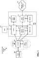
- FIG. 1 is a diagram illustrating an LTE network architecture 100.
- the LTE network architecture 100 may be referred to as an Evolved Packet System (EPS) 100.
- the EPS 100 may include one or more user equipment (UE) 102, an Evolved UMTS Terrestrial Radio Access Network (E-UTRAN) 104, an Evolved Packet Core (EPC) 110, a Home Subscriber Server (HSS) 120, and an Operator's Internet Protocol (IP) Services 122.
- the EPS can interconnect with other access networks, but for simplicity those entities/interfaces are not shown.
- the EPS provides packet-switched services, however, as those skilled in the art will readily appreciate, the various concepts presented throughout this disclosure may be extended to networks providing circuit-switched services.
- the E-UTRAN includes the evolved Node B (eNB) 106 and other eNBs 108.
- the eNB 106 provides user and control planes protocol terminations toward the UE 102.
- the eNB 106 may be connected to the other eNBs 108 via a backhaul (e.g., an X2 interface).
- the eNB 106 may also be referred to as a base station, a Node B, an access point, a base transceiver station, a radio base station, a radio transceiver, a transceiver function, a basic service set (BSS), an extended service set (ESS), or some other suitable terminology.
- the eNB 106 provides an access point to the EPC 110 for a UE 102.
- Examples of UEs 102 include a cellular phone, a smart phone, a session initiation protocol (SIP) phone, a laptop, a personal digital assistant (PDA), a satellite radio, a global positioning system, a multimedia device, a video device, a digital audio player (e.g., MP3 player), a camera, a game console, a tablet, or any other similar functioning device.
- SIP session initiation protocol
- PDA personal digital assistant
- satellite radio a global positioning system
- multimedia device e.g., a digital audio player (e.g., MP3 player), a camera, a game console, a tablet, or any other similar functioning device.
- MP3 player digital audio player
- the UE 102 may also be referred to by those skilled in the art as a mobile station, a subscriber station, a mobile unit, a subscriber unit, a wireless unit, a remote unit, a mobile device, a wireless device, a wireless communications device, a remote device, a mobile subscriber station, an access terminal, a mobile terminal, a wireless terminal, a remote terminal, a handset, a user agent, a mobile client, a client, or some other suitable terminology.
- the eNB 106 is connected to the EPC 110.
- the EPC 110 may include a Mobility Management Entity (MME) 112, other MMEs 114, a Serving Gateway 116, a Multimedia Broadcast Multicast Service (MBMS) Gateway 124, a Broadcast Multicast Service Center (BM-SC) 126, and a Packet Data Network (PDN) Gateway 118.
- MME Mobility Management Entity
- MBMS Multimedia Broadcast Multicast Service
- BM-SC Broadcast Multicast Service Center
- PDN Packet Data Network
- the MME 112 is the control node that processes the signaling between the UE 102 and the EPC 110.
- the MME 112 provides bearer and connection management. All user IP packets are transferred through the Serving Gateway 116, which itself is connected to the PDN Gateway 118.
- the PDN Gateway 118 provides UE IP address allocation as well as other functions.
- the PDN Gateway 118 is connected to the Operator's IP Services 122.
- the Operator's IP Services 122 may include the Internet, an intranet, an IP Multimedia Subsystem (IMS), and a PS Streaming Service (PSS).
- the BM-SC 126 may provide functions for MBMS user service provisioning and delivery.
- the BM-SC 126 may serve as an entry point for content provider MBMS transmission, may be used to authorize and initiate MBMS Bearer Services within a PLMN, and may be used to schedule and deliver MBMS transmissions.
- the MBMS Gateway 124 may be used to distribute MBMS traffic to the eNBs (e.g., 106, 108) belonging to a Multicast Broadcast Single Frequency Network (MBSFN) area broadcasting a particular service, and may be responsible for session management (start/stop) and for collecting eMBMS related charging information.
- MMSFN Multicast Broadcast Single Frequency Network
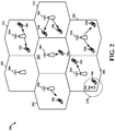
- FIG. 2 is a diagram illustrating an example of an access network 200 in an LTE network architecture.
- the access network 200 is divided into a number of cellular regions (cells) 202.
- One or more lower power class eNBs 208 may have cellular regions 210 that overlap with one or more of the cells 202.
- the lower power class eNB 208 may be a femto cell (e.g., home eNB (HeNB)), pico cell, micro cell, or remote radio head (RRH).
- HeNB home eNB
- RRH remote radio head
- the macro eNBs 204 are each assigned to a respective cell 202 and are configured to provide an access point to the EPC 110 for all the UEs 206 in the cells 202.
- the eNBs 204 are responsible for all radio related functions including radio bearer control, admission control, mobility control, scheduling, security, and connectivity to the serving gateway 116.
- An eNB may support one or multiple (e.g., three) cells (also referred to as a sector).
- the term "cell” can refer to the smallest coverage area of an eNB and/or an eNB subsystem serving are particular coverage area. Further, the terms “eNB,” “base station,” and “cell” may be used interchangeably herein.
- the modulation and multiple access scheme employed by the access network 200 may vary depending on the particular telecommunications standard being deployed.
- OFDM is used on the DL
- SC-FDMA is used on the UL to support both frequency division duplex (FDD) and time division duplex (TDD).
- FDD frequency division duplex
- TDD time division duplex
- FDD frequency division duplex
- TDD time division duplex
- EV-DO Evolution-Data Optimized
- UMB Ultra Mobile Broadband
- EV-DO and UMB are air interface standards promulgated by the 3rd Generation Partnership Project 2 (3GPP2) as part of the CDMA2000 family of standards and employs CDMA to provide broadband Internet access to mobile stations. These concepts may also be extended to Universal Terrestrial Radio Access (UTRA) employing Wideband-CDMA (W-CDMA) and other variants of CDMA, such as TD-SCDMA; Global System for Mobile Communications (GSM) employing TDMA; and Evolved UTRA (E-UTRA), IEEE 802.11 (Wi-Fi), IEEE 802.16 (WiMAX), IEEE 802.20, and Flash-OFDM employing OFDMA.
- UTRA, E-UTRA, UMTS, LTE and GSM are described in documents from the 3GPP organization.
- CDMA2000 and UMB are described in documents from the 3GPP2 organization. The actual wireless communication standard and the multiple access technology employed will depend on the specific application and the overall design constraints imposed on the system.
- the eNBs 204 may have multiple antennas supporting MIMO technology.
- MIMO technology enables the eNBs 204 to exploit the spatial domain to support spatial multiplexing, beamforming, and transmit diversity.
- Spatial multiplexing may be used to transmit different streams of data simultaneously on the same frequency.
- the data streams may be transmitted to a single UE 206 to increase the data rate or to multiple UEs 206 to increase the overall system capacity. This is achieved by spatially precoding each data stream (i.e., applying a scaling of an amplitude and a phase) and then transmitting each spatially precoded stream through multiple transmit antennas on the DL.
- the spatially precoded data streams arrive at the UE(s) 206 with different spatial signatures, which enables each of the UE(s) 206 to recover the one or more data streams destined for that UE 206.
- each UE 206 transmits a spatially precoded data stream, which enables the eNB 204 to identify the source of each spatially precoded data stream.
- Beamforming may be used to focus the transmission energy in one or more directions. This may be achieved by spatially precoding the data for transmission through multiple antennas. To achieve good coverage at the edges of the cell, a single stream beamforming transmission may be used in combination with transmit diversity.
- OFDM is a spread-spectrum technique that modulates data over a number of subcarriers within an OFDM symbol.
- the subcarriers are spaced apart at precise frequencies. The spacing provides "orthogonality" that enables a receiver to recover the data from the subcarriers.
- a guard interval e.g., cyclic prefix
- the UL may use SC-FDMA in the form of a DFT-spread OFDM signal to compensate for high peak-to-average power ratio (PAPR).
- PAPR peak-to-average power ratio
- FIG. 3 is a diagram 300 illustrating an example of a DL frame structure in LTE.
- a frame (10 ms) may be divided into 10 equally sized subframes. Each subframe may include two consecutive time slots.
- a resource grid may be used to represent two time slots, each time slot including a resource block.
- the resource grid is divided into multiple resource elements.
- a resource block contains 12 consecutive subcarriers in the frequency domain and, for a normal cyclic prefix in each OFDM symbol, 7 consecutive OFDM symbols in the time domain, or 84 resource elements.
- For an extended cyclic prefix a resource block contains 6 consecutive OFDM symbols in the time domain and has 72 resource elements.
- Some of the resource elements, indicated as R 302, 304, include DL reference signals (DL-RS).
- DL-RS DL reference signals
- the DL-RS include Cell-specific RS (CRS) (also sometimes called common RS) 302 and UE-specific RS (UE-RS) 304.
- UE-RS 304 are transmitted only on the resource blocks upon which the corresponding physical DL shared channel (PDSCH) is mapped.
- PDSCH physical DL shared channel
- the number of bits carried by each resource element depends on the modulation scheme. Thus, the more resource blocks that a UE receives and the higher the modulation scheme, the higher the data rate for the UE.
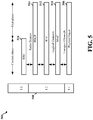
- FIG. 4 is a diagram 400 illustrating an example of an UL frame structure in LTE.
- the available resource blocks for the UL may be partitioned into a data section and a control section.
- the control section may be formed at the two edges of the system bandwidth and may have a configurable size.
- the resource blocks in the control section may be assigned to UEs for transmission of control information.
- the data section may include all resource blocks not included in the control section.
- the UL frame structure results in the data section including contiguous subcarriers, which may allow a single UE to be assigned all of the contiguous subcarriers in the data section.
- a UE may be assigned resource blocks 410a, 410b in the control section to transmit control information to an eNB.
- the UE may also be assigned resource blocks 420a, 420b in the data section to transmit data to the eNB.
- the UE may transmit control information in a physical UL control channel (PUCCH) on the assigned resource blocks in the control section.
- the UE may transmit only data or both data and control information in a physical UL shared channel (PUSCH) on the assigned resource blocks in the data section.
- a UL transmission may span both slots of a subframe and may hop across frequency.
- a set of resource blocks may be used to perform initial system access and achieve UL synchronization in a physical random access channel (PRACH) 430.
- the PRACH 430 carries a random sequence and cannot carry any UL data/signaling.
- Each random access preamble occupies a bandwidth corresponding to six consecutive resource blocks.
- the starting frequency is specified by the network. That is, the transmission of the random access preamble is restricted to certain time and frequency resources. There is no frequency hopping for the PRACH.
- the PRACH attempt is carried in a single subframe (1 ms) or in a sequence of few contiguous subframes and a UE can make only a single PRACH attempt per frame (10 ms).
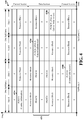
- FIG. 5 is a diagram 500 illustrating an example of a radio protocol architecture for the user and control planes in LTE.
- the radio protocol architecture for the UE and the eNB is shown with three layers: Layer 1, Layer 2, and Layer 3.
- Layer 1 (L1 layer) is the lowest layer and implements various physical layer signal processing functions.
- the L1 layer will be referred to herein as the physical layer 506.
- Layer 2 (L2 layer) 508 is above the physical layer 506 and is responsible for the link between the UE and eNB over the physical layer 506.
- the L2 layer 508 includes a media access control (MAC) sublayer 510, a radio link control (RLC) sublayer 512, and a packet data convergence protocol (PDCP) 514 sublayer, which are terminated at the eNB on the network side.
- MAC media access control
- RLC radio link control
- PDCP packet data convergence protocol
- the UE may have several upper layers above the L2 layer 508 including a network layer (e.g., IP layer) that is terminated at the PDN gateway 118 on the network side, and an application layer that is terminated at the other end of the connection (e.g., far end UE, server, etc.).
- IP layer e.g., IP layer
- the PDCP sublayer 514 provides multiplexing between different radio bearers and logical channels.
- the PDCP sublayer 514 also provides header compression for upper layer data packets to reduce radio transmission overhead, security by ciphering the data packets, and handover support for UEs between eNBs.
- the RLC sublayer 512 provides segmentation and reassembly of upper layer data packets, retransmission of lost data packets, and reordering of data packets to compensate for out-of-order reception due to hybrid automatic repeat request (HARQ).
- HARQ hybrid automatic repeat request
- the MAC sublayer 510 provides multiplexing between logical and transport channels.
- the MAC sublayer 510 is also responsible for allocating the various radio resources (e.g., resource blocks) in one cell among the UEs.
- the MAC sublayer 510 is also responsible for HARQ operations.
- the radio protocol architecture for the UE and eNB is substantially the same for the physical layer 506 and the L2 layer 508 with the exception that there is no header compression function for the control plane.
- the control plane also includes a radio resource control (RRC) sublayer 516 in Layer 3 (L3 layer).
- RRC sublayer 516 is responsible for obtaining radio resources (e.g., radio bearers) and for configuring the lower layers using RRC signaling between the eNB and the UE.
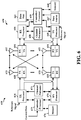
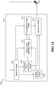
- FIG. 6 is a block diagram of an eNB 610 in communication with a UE 650 in an access network.
- upper layer packets from the core network are provided to a controller/processor 675.
- the controller/processor 675 implements the functionality of the L2 layer.
- the controller/processor 675 provides header compression, ciphering, packet segmentation and reordering, multiplexing between logical and transport channels, and radio resource allocations to the UE 650 based on various priority metrics.
- the controller/processor 675 is also responsible for HARQ operations, retransmission of lost packets, and signaling to the UE 650.
- the transmit (TX) processor 616 implements various signal processing functions for the L1 layer (i.e., physical layer).
- the signal processing functions include coding and interleaving to facilitate forward error correction (FEC) at the UE 650 and mapping to signal constellations based on various modulation schemes (e.g., binary phase-shift keying (BPSK), quadrature phase-shift keying (QPSK), M-phase-shift keying (M-PSK), M-quadrature amplitude modulation (M-QAM)).
- FEC forward error correction
- BPSK binary phase-shift keying
- QPSK quadrature phase-shift keying
- M-PSK M-phase-shift keying
- M-QAM M-quadrature amplitude modulation
- Each stream is then mapped to an OFDM subcarrier, multiplexed with a reference signal (e.g., pilot) in the time and/or frequency domain, and then combined together using an Inverse Fast Fourier Transform (IFFT) to produce a physical channel carrying a time domain OFDM symbol stream.
- the OFDM stream is spatially precoded to produce multiple spatial streams.
- Channel estimates from a channel estimator 674 may be used to determine the coding and modulation scheme, as well as for spatial processing.
- the channel estimate may be derived from a reference signal and/or channel condition feedback transmitted by the UE 650.
- Each spatial stream may then be provided to a different antenna 620 via a separate transmitter 618TX.
- Each transmitter 618TX may modulate an RF carrier with a respective spatial stream for transmission.
- each receiver 654RX receives a signal through its respective antenna 652.
- Each receiver 654RX recovers information modulated onto an RF carrier and provides the information to the receive (RX) processor 656.
- the RX processor 656 implements various signal processing functions of the L1 layer.
- the RX processor 656 may perform spatial processing on the information to recover any spatial streams destined for the UE 650. If multiple spatial streams are destined for the UE 650, they may be combined by the RX processor 656 into a single OFDM symbol stream.
- the RX processor 656 then converts the OFDM symbol stream from the time-domain to the frequency domain using a Fast Fourier Transform (FFT).
- FFT Fast Fourier Transform
- the symbols on each subcarrier, and the reference signal, are recovered and demodulated by determining the most likely signal constellation points transmitted by the eNB 610. These soft decisions may be based on channel estimates computed by the channel estimator 658. The soft decisions are then decoded and deinterleaved to recover the data and control signals that were originally transmitted by the eNB 610 on the physical channel. The data and control signals are then provided to the controller/processor 659.
- the controller/processor 659 implements the L2 layer.
- the controller/processor can be associated with a memory 660 that stores program codes and data.
- the memory 660 may be referred to as a computer-readable medium.
- the controller/processor 659 provides demultiplexing between transport and logical channels, packet reassembly, deciphering, header decompression, control signal processing to recover upper layer packets from the core network.
- the upper layer packets are then provided to a data sink 662, which represents all the protocol layers above the L2 layer.
- Various control signals may also be provided to the data sink 662 for L3 processing.
- the controller/processor 659 is also responsible for error detection using an acknowledgement (ACK) and/or negative acknowledgement (NACK) protocol to support HARQ operations.
- ACK acknowledgement
- NACK negative acknowledgement
- a data source 667 is used to provide upper layer packets to the controller/processor 659.
- the data source 667 represents all protocol layers above the L2 layer.
- the controller/processor 659 implements the L2 layer for the user plane and the control plane by providing header compression, ciphering, packet segmentation and reordering, and multiplexing between logical and transport channels based on radio resource allocations by the eNB 610.
- the controller/processor 659 is also responsible for HARQ operations, retransmission of lost packets, and signaling to the eNB 610.
- Channel estimates derived by a channel estimator 658 from a reference signal or feedback transmitted by the eNB 610 may be used by the TX processor 668 to select the appropriate coding and modulation schemes, and to facilitate spatial processing.
- the spatial streams generated by the TX processor 668 may be provided to different antenna 652 via separate transmitters 654TX. Each transmitter 654TX may modulate an RF carrier with a respective spatial stream for transmission.
- the UL transmission is processed at the eNB 610 in a manner similar to that described in connection with the receiver function at the UE 650.
- Each receiver 618RX receives a signal through its respective antenna 620.
- Each receiver 618RX recovers information modulated onto an RF carrier and provides the information to a RX processor 670.
- the RX processor 670 may implement the L1 layer.
- the controller/processor 675 implements the L2 layer.
- the controller/processor 675 can be associated with a memory 676 that stores program codes and data.
- the memory 676 may be referred to as a computer-readable medium.
- the control/processor 675 provides demultiplexing between transport and logical channels, packet reassembly, deciphering, header decompression, control signal processing to recover upper layer packets from the UE 650.
- Upper layer packets from the controller/processor 675 may be provided to the core network.
- the controller/processor 675 is also responsible for error detection using an ACK and/or NACK protocol to support HARQ operations.
- FIG. 7 is a diagram of a device-to-device communications system 700.
- the device-to-device (D2D) communications system 700 includes a plurality of wireless devices 704, 706, 708, 710.
- the device-to-device communications system 700 may overlap with a cellular communications system, such as for example, a wireless wide area network (WWAN).
- WWAN wireless wide area network
- Some of the wireless devices 704, 706, 708, 710 may communicate together in device-to-device communication using the DL/UL WWAN spectrum, some may communicate with the base station 702, and some may do both.
- the wireless devices 708, 710 are in device-to-device communication and the wireless devices 704, 706 are in device-to-device communication.
- the wireless devices 704, 706 are also communicating with the base station 702.
- the exemplary methods and apparatuses discussed infra are applicable to any of a variety of wireless device-to-device communications systems, such as for example, a wireless device-to-device communication system based on FlashLinQ, WiMedia, Bluetooth, ZigBee, or Wi-Fi based on the IEEE 802.11 standard.
- a wireless device-to-device communication system based on FlashLinQ, WiMedia, Bluetooth, ZigBee, or Wi-Fi based on the IEEE 802.11 standard.
- the exemplary methods and apparatus are discussed within the context of LTE.
- one of ordinary skill in the art would understand that the exemplary methods and apparatuses are applicable more generally to a variety of other wireless device-to-device communication systems.
- a baseline design for broadcast communication may be to divide a bandwidth into narrowband subchannels, wherein each transmitter of a number of neighboring transmitters may select one subchannel to transmit a signal. Subchannel selection may be based on received energy measurements.
- a limit on system performance may be imposed by in-band emissions.
- An in-band emission is interference caused by one transmitter transmitting on one subchannel and imposed on another transmitter transmitting to a receiver on another subchannel.
- methods and apparatuses are provided to improve system performance by facilitating subchannel selection while aware of IBE on the subchannels of the bandwidth.
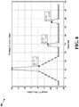
- FIG. 8 is a diagram 800 illustrating an in-band emissions model.
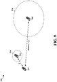
- FIG. 9 is a diagram 900 illustrating an outage area (e.g., zones, regions, etc.) caused by a transmitter. Two observations may be utilized for determining a subchannel selection algorithm. First, not all subchannels see the same amount of interference. Referring to FIG. 8 , the plot of the in-band emissions model shows that nearby subchannels as well as other subchannels (e.g., I/Q or image subchannels) experience more interference.
- subchannels e.g., I/Q or image subchannels
- a transmitter TX1 902 is a distance d from a neighboring transmitter TX2 904.
- the transmitter TX1 902 is also at a distance greater than d from another neighboring transmitter TX3 906. Also shown are an outage zone 914 of the transmitter TX2 904 and an outage zone 916 of the transmitter TX3 906.
- An outage zone may be defined as a geographical area (region) related to a neighboring transmitter (e.g., TX2 904 or TX3 906) where an intended receiver of a signal from a home transmitter (e.g., TX1 902) experiences a signal-to-interference-plus-noise ratio (SINR) of less than a threshold (e.g., 0 dB).
- a neighboring transmitter e.g., TX2 904 or TX3 906
- SINR signal-to-interference-plus-noise ratio
- the transmitter TX2 904 that is at the distance d from the transmitter TX1 902 may cause a circular outage zone 914 having a radius of approximately d/10.
- An intended receiver of a signal from the transmitter TX1 902 that is 10 times closer to the transmitter TX2 904 will be in the outage zone 914 of the transmitter TX2 904 due to the IBE of the transmitter TX2 904.
- the intended receiver of the signal from the transmitter TX1 902 will experience SINR of less than the threshold (e.g., 0 dB) when in the outage zone 914 of the transmitter TX2 904.
- a transmitter farther away from the transmitter TX1 902 e.g., transmitter TX3 906 at a distance greater than d
- a transmitter farther away from the transmitter TX1 902 e.g., transmitter TX3 906 at a distance greater than d
- transmitter TX2 904 e.g., transmitter TX2 904 closer to the transmitter.
- each transmitter of a number of neighboring transmitters may monitor its surroundings and determine which subchannels of a given bandwidth are occupied by the neighboring transmitters.
- Each transmitter may also monitor a relative strength of each neighboring transmitter.
- a transmitter may estimate an outage zone (outage region) related to a respective subchannel if the transmitter was to use the respective subchannel for transmitting a signal to an intended receiver.
- the estimation may include an estimate of the IBE based on a model (e.g., pattern shown in FIG. 8 ) and/or an estimate of an outage zone based on a pathloss estimate to a neighboring transmitter transmitting on the respective subchannel.
- the following properties may be applied during the estimation: 1) a subchannel with larger IBE implies a larger outage zone; and 2) a weaker transmitter implies a larger outage zone.
- the transmitter may then select a subchannel with a smallest estimated outage zone.
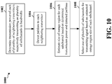
- FIG. 10 is a flow chart 1000 of a method of wireless communication. The method may be performed by a first transmitter (e.g., UE or any one of wireless devices 704, 706, 708, or 710 of FIG. 7 ).
- a first transmitter e.g., UE or any one of wireless devices 704, 706, 708, or 710 of FIG. 7 .
- the first transmitter determines a transmission power of each of a plurality of neighboring transmitters respectively transmitting on a plurality of subchannels in a bandwidth.
- the transmission power determination may include determining an in-band emission (IBE) power of a neighboring transmitter transmitting on a respective subchannel and/or determining a transmission power of a neighboring transmitter transmitting an intended transmission signal.
- IBE in-band emission
- the IBE power for each of the plurality of neighboring transmitters respectively transmitting on the plurality of subchannels is determined based on a model for IBE and a determination of the transmission power of the intended transmission signal on a respective subchannel.
- the first transmitter detects a pathloss to each of the plurality of neighboring transmitters respectively transmitting on the plurality of subchannels.
- the first transmitter may then select one of the plurality of subchannels for transmitting a signal based on the determined transmission power on each of the plurality of subchannels and the detected pathloss to each of the plurality of neighboring transmitters respectively transmitting on the plurality of subchannels.
- the first transmitter estimates a size of an outage region for a subchannel based on a determined transmission power of a neighboring transmitter transmitting on the subchannel and the detected pathloss to the neighboring transmitter.
- the outage region may include a geographical area where an intended receiver of the signal from the first transmitter experiences a signal-to-interference-plus-noise ratio (SINR) of less than a threshold (e.g., 0 dB).
- SINR signal-to-interference-plus-noise ratio
- the determined transmission power of the neighboring transmitter transmitting on the subchannel indicates the size of the outage region for the subchannel.
- the detected pathloss to the neighboring transmitter transmitting on the subchannel also indicates the size of the outage region for the subchannel.
- the first transmitter selects the one of the plurality of subchannels based on the estimated outage region size for each of the plurality of subchannels. In an aspect, the first transmitter selects the one of the plurality of subchannels based on the subchannel having a smallest estimated outage region size.
- FIG. 11 is a conceptual data flow diagram 1100 illustrating the data flow between different modules/means/components in an exemplary apparatus 1102.
- the apparatus may be a first transmitter (e.g., UE or any one of wireless devices 704, 706, 708, or 710 of FIG. 7 ).
- the apparatus includes a receiving module 1104, a transmission power determining module 1106, a pathloss detecting module 1108, an outage region estimating module 1110, a subchannel processing module 1112, and a transmission module 1114.
- the transmission power determining module 1106 determines (via the receiving module 1104 and the transmission module 1114) a transmission power of each of a plurality of neighboring transmitters (e.g., neighboring transmitter(s) 1150) respectively transmitting on a plurality of subchannels in a bandwidth.
- the transmission power determination may include determining an in-band emission (IBE) power of a neighboring transmitter transmitting on a respective subchannel and/or determining a transmission power of a neighboring transmitter transmitting an intended transmission signal.
- IBE power for each of the plurality of neighboring transmitters respectively transmitting on the plurality of subchannels is determined based on a model for IBE and a determination of the transmission power of the intended transmission signal on a respective subchannel.
- the pathloss detecting module 1108 detects (via the receiving module 1104 and the transmission module 1114) a pathloss to each of the plurality of neighboring transmitters respectively transmitting on the plurality of subchannels.
- the apparatus 1102 may select one of the plurality of subchannels for transmitting a signal (via the transmission module 1114) based on the determined transmission power on each of the plurality of subchannels and the detected pathloss to each of the plurality of neighboring transmitters respectively transmitting on the plurality of subchannels.
- the outage region estimating module 1110 estimates a size of an outage region for a subchannel based on a determined transmission power of a neighboring transmitter transmitting on the subchannel and the detected pathloss to the neighboring transmitter.
- the outage region may include a geographical area where an intended receiver of the signal from the first transmitter experiences a signal-to-interference-plus-noise ratio (SINR) of less than a threshold (e.g., 0 dB).
- SINR signal-to-interference-plus-noise ratio
- the determined transmission power of the neighboring transmitter transmitting on the subchannel indicates the size of the outage region for the subchannel.
- the detected pathloss to the neighboring transmitter transmitting on the subchannel also indicates the size of the outage region for the subchannel.
- the subchannel processing module 1112 selects the one of the plurality of subchannels based on the estimated outage region size for each of the plurality of subchannels. In an aspect, the subchannel processing module 1112 selects the one of the plurality of subchannels based on the subchannel having a smallest estimated outage region size.
- the apparatus may include additional modules that perform each of the steps of the algorithm in the aforementioned flow chart of FIG. 10 .
- each step in the aforementioned flow chart of FIG. 10 may be performed by a module and the apparatus may include one or more of those modules.
- the modules may be one or more hardware components specifically configured to carry out the stated processes/algorithm, implemented by a processor configured to perform the stated processes/algorithm, stored within a computer-readable medium for implementation by a processor, or some combination thereof.
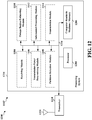
- FIG. 12 is a diagram 1200 illustrating an example of a hardware implementation for an apparatus 1102' employing a processing system 1214.
- the processing system 1214 may be implemented with a bus architecture, represented generally by the bus 1224.
- the bus 1224 may include any number of interconnecting buses and bridges depending on the specific application of the processing system 1214 and the overall design constraints.
- the bus 1224 links together various circuits including one or more processors and/or hardware modules, represented by the processor 1204, the modules 1104, 1106, 1108, 1110, 1112, 1114, and the computer-readable medium / memory 1206.
- the bus 1224 may also link various other circuits such as timing sources, peripherals, voltage regulators, and power management circuits, which are well known in the art, and therefore, will not be described any further.
- the processing system 1214 may be coupled to a transceiver 1210.
- the transceiver 1210 is coupled to one or more antennas 1220.
- the transceiver 1210 provides a means for communicating with various other apparatus over a transmission medium.
- the transceiver 1210 receives a signal from the one or more antennas 1220, extracts information from the received signal, and provides the extracted information to the processing system 1214, specifically the receiving module 1104.
- the transceiver 1210 receives information from the processing system 1214, specifically the transmission module 1114, and based on the received information, generates a signal to be applied to the one or more antennas 1220.
- the processing system 1214 includes a processor 1204 coupled to a computer-readable medium / memory 1206.
- the processor 1204 is responsible for general processing, including the execution of software stored on the computer-readable medium / memory 1206.
- the software when executed by the processor 1204, causes the processing system 1214 to perform the various functions described supra for any particular apparatus.
- the computer-readable medium / memory 1206 may also be used for storing data that is manipulated by the processor 1204 when executing software.
- the processing system further includes at least one of the modules 1104, 1106, 1108, 1110, 1112, and 1114.
- the modules may be software modules running in the processor 1204, resident/stored in the computer readable medium / memory 1206, one or more hardware modules coupled to the processor 1204, or some combination thereof.
- the processing system 1214 may be a component of the UE 650 and may include the memory 660 and/or at least one of the TX processor 668, the RX processor 656, and the controller/processor 659.
- the apparatus 1102/1102' for wireless communication includes means for determining a transmission power of each of a plurality of neighboring transmitters respectively transmitting on a plurality of subchannels in a bandwidth, means for detecting a pathloss to each of the plurality of neighboring transmitters respectively transmitting on the plurality of subchannels, means for selecting one of the plurality of subchannels for transmitting a signal based on the determined transmission power on each of the plurality of subchannels and the detected pathloss to each of the plurality of neighboring transmitters respectively transmitting on the plurality of subchannels, and means for estimating a size of an outage region for a subchannel based on a determined transmission power of a neighboring transmitter transmitting on the subchannel and the detected pathloss to the neighboring transmitter, wherein the means for selecting is configured to select the one of the plurality of subchannels based on the estimated outage region size for each of the plurality of subchannels.
- the aforementioned means may be one or more of the aforementioned modules of the apparatus 1102 and/or the processing system 1214 of the apparatus 1102' configured to perform the functions recited by the aforementioned means.
- the processing system 1214 may include the TX Processor 668, the RX Processor 656, and the controller/processor 659.
- the aforementioned means may be the TX Processor 668, the RX Processor 656, and the controller/processor 659 configured to perform the functions recited by the aforementioned means.
- Combinations such as “at least one of A, B, or C,” “at least one of A, B, and C,” and “A, B, C, or any combination thereof” include any combination of A, B, and/or C, and may include multiples of A, multiples of B, or multiples of C.
- combinations such as “at least one of A, B, or C,” “at least one of A, B, and C,” and “A, B, C, or any combination thereof” may be A only, B only, C only, A and B, A and C, B and C, or A and B and C, where any such combinations may contain one or more member or members of A, B, or C.
Claims (9)
- Un procédé de communication sans fil au niveau d'un émetteur, comprenant :la détermination, au niveau de l'émetteur (902), d'une puissance de transmission de chaque émetteur d'une pluralité d'émetteurs voisins (904, 906) transmettant respectivement sur une pluralité de sous-canaux,la détection d'un affaiblissement de propagation à partir de l'émetteur (902) vers chaque émetteur de la pluralité d'émetteurs voisins (904, 906) transmettant respectivement sur la pluralité de sous-canaux, caractérisé par :l'estimation d'une taille de zone d'interruption pour chaque sous-canal de la pluralité de sous-canaux (914, 916), où l'estimation de la taille de zone d'interruption pour un sous-canal (914, 916) est basée sur une puissance de transmission déterminée d'un émetteur voisin (904, 906) transmettant sur le sous-canal et sur l'affaiblissement de propagation détecté vers l'émetteur voisin (904, 906), etla sélection d'un sous-canal de la pluralité de sous-canaux destiné à la transmission d'un signal à partir de l'émetteur (902), où la sélection est basée sur la taille de zone d'interruption estimée de chaque sous-canal de la pluralité de sous-canaux (914, 916).
- Le procédé selon la Revendication 1, où la détermination de la puissance de transmission comprend la détermination d'au moins un élément parmi :une puissance d'émission dans la bande, IBE, ouune puissance de transmission d'un signal de transmission souhaité sur les sous-canaux.
- Le procédé selon la Revendication 2, où la puissance IBE pour chaque émetteur de la pluralité d'émetteurs voisins (904, 906) transmettant respectivement sur la pluralité de sous-canaux est déterminée en fonction d'un modèle pour l'IBE d'un émetteur voisin et/ou d'une détermination de la puissance de transmission de l'émetteur voisin du signal de transmission souhaité sur un sous-canal respectif.
- Le procédé selon la Revendication 1, où le sous-canal de la pluralité de sous-canaux est sélectionné en fonction du sous-canal possédant une taille de zone d'interruption estimée la plus petite (914, 916).
- Le procédé selon la Revendication 1, où une zone d'interruption (914, 916) comprend une zone géographique dans laquelle un récepteur souhaité du signal à partir de l'émetteur subit un rapport signal sur brouillage plus bruit, SINR, inférieur à un seuil.
- Le procédé selon la Revendication 1, où la puissance de transmission déterminée de l'émetteur voisin (904, 906) transmettant sur le sous-canal indique la taille de zone d'interruption (914, 916) pour le sous-canal.
- Le procédé selon la Revendication 1, où l'affaiblissement de propagation détecté vers l'émetteur voisin (904, 906) transmettant sur le sous-canal indique la taille de zone d'interruption (914, 916) pour le sous-canal.
- Un émetteur destiné à une communication sans fil, comprenant un moyen d'exécution du procédé selon la Revendication 1.
- Un support lisible par ordinateur conservant en mémoire du code informatique exécutable pour une communication sans fil au niveau d'un émetteur, qui, lorsqu'il est exécuté par un processeur, exécute le procédé selon la Revendication 1.
Applications Claiming Priority (3)
| Application Number | Priority Date | Filing Date | Title |
|---|---|---|---|
| US201361882975P | 2013-09-26 | 2013-09-26 | |
| US14/331,788 US9185667B2 (en) | 2013-09-26 | 2014-07-15 | IBE aware channel selection |
| PCT/US2014/057007 WO2015048031A1 (fr) | 2013-09-26 | 2014-09-23 | Sélection de canal prenant en charge ibe |
Publications (2)
| Publication Number | Publication Date |
|---|---|
| EP3050376A1 EP3050376A1 (fr) | 2016-08-03 |
| EP3050376B1 true EP3050376B1 (fr) | 2017-07-05 |
Family
ID=52691384
Family Applications (1)
| Application Number | Title | Priority Date | Filing Date |
|---|---|---|---|
| EP14783954.2A Active EP3050376B1 (fr) | 2013-09-26 | 2014-09-23 | Sélection de canal prenant en charge ibe |
Country Status (7)
| Country | Link |
|---|---|
| US (1) | US9185667B2 (fr) |
| EP (1) | EP3050376B1 (fr) |
| JP (1) | JP6509825B2 (fr) |
| KR (1) | KR102182948B1 (fr) |
| CN (1) | CN105580462B (fr) |
| BR (1) | BR112016006604A2 (fr) |
| WO (1) | WO2015048031A1 (fr) |
Families Citing this family (5)
| Publication number | Priority date | Publication date | Assignee | Title |
|---|---|---|---|---|
| US10263753B2 (en) * | 2015-02-19 | 2019-04-16 | Apple Inc. | Sub-channel selection based on transmit power |
| WO2017146773A1 (fr) * | 2016-02-26 | 2017-08-31 | Intel IP Corporation | Commande de puissance des liaisons dans des systèmes de formation de faisceau |
| EP3282618A1 (fr) * | 2016-08-09 | 2018-02-14 | Panasonic Intellectual Property Corporation of America | Retransmissions initiales améliorées des données pour des transmissions v2x |
| US10299225B2 (en) * | 2016-09-30 | 2019-05-21 | Qualcomm Incorporated | User equipment management limiting transmit output power in protection zones |
| US10939359B2 (en) | 2019-06-24 | 2021-03-02 | Nxp B.V. | Location-based communication |
Family Cites Families (15)
| Publication number | Priority date | Publication date | Assignee | Title |
|---|---|---|---|---|
| GB9820427D0 (en) * | 1998-09-18 | 1998-11-11 | Northern Telecom Ltd | Wireline communication system and method of frequency allocation therin |
| US6690944B1 (en) * | 1999-04-12 | 2004-02-10 | Nortel Networks Limited | Power control of a multi-subchannel mobile station in a mobile communication system |
| US7151740B2 (en) * | 2001-02-28 | 2006-12-19 | Cingular Wireless Ii, Llc | Transmit power control for an OFDM-based wireless communication system |
| US8897828B2 (en) * | 2004-08-12 | 2014-11-25 | Intellectual Ventures Holding 81 Llc | Power control in a wireless communication system |
| US20070202867A1 (en) | 2006-02-24 | 2007-08-30 | Waltho Alan E | Facilitating reuse of frequencies by unlicensed cognitive devices |
| US7555293B2 (en) * | 2006-03-01 | 2009-06-30 | Research In Motion Limited | System for determining RF path loss between an RF source and an RF receiver and related methods |
| CN101478333B (zh) * | 2008-01-03 | 2012-10-03 | 展讯通信(上海)有限公司 | 专用物理信道重新同步后的发射功率设置方法和装置 |
| GB2457431A (en) * | 2008-01-28 | 2009-08-19 | Fujitsu Lab Of Europ Ltd | Interference mitigation method in a wireless network |
| CN101572944B (zh) * | 2008-04-29 | 2013-12-04 | 华为技术有限公司 | 随机接入中资源选择方法和终端设备 |
| US8295153B2 (en) | 2008-12-23 | 2012-10-23 | Nokia Corporation | Radio resource sharing |
| JP5227938B2 (ja) * | 2008-12-26 | 2013-07-03 | 株式会社エヌ・ティ・ティ・ドコモ | ユーザ装置及び移動通信方法 |
| US8605644B2 (en) * | 2009-02-12 | 2013-12-10 | Nokia Siemens Networks Oy | Transmission power control for sounding signal for wireless networks |
| US8725192B2 (en) * | 2009-07-24 | 2014-05-13 | Qualcomm Incorporated | Beacon transmit power schemes |
| KR101756807B1 (ko) * | 2011-12-23 | 2017-07-13 | 한국전자통신연구원 | 무선 통신 시스템의 전송 전력 제어 장치 및 방법 |
| US10602452B2 (en) | 2012-11-20 | 2020-03-24 | Huawei Technologies Co., Ltd. | System and method for device-to-device operation in a cellular communications system |
-
2014
- 2014-07-15 US US14/331,788 patent/US9185667B2/en active Active
- 2014-09-23 WO PCT/US2014/057007 patent/WO2015048031A1/fr active Application Filing
- 2014-09-23 CN CN201480052806.3A patent/CN105580462B/zh active Active
- 2014-09-23 EP EP14783954.2A patent/EP3050376B1/fr active Active
- 2014-09-23 JP JP2016516834A patent/JP6509825B2/ja active Active
- 2014-09-23 BR BR112016006604A patent/BR112016006604A2/pt active Search and Examination
- 2014-09-23 KR KR1020167010725A patent/KR102182948B1/ko active IP Right Grant
Also Published As
| Publication number | Publication date |
|---|---|
| CN105580462B (zh) | 2019-06-04 |
| EP3050376A1 (fr) | 2016-08-03 |
| KR102182948B1 (ko) | 2020-11-25 |
| JP2016534591A (ja) | 2016-11-04 |
| CN105580462A (zh) | 2016-05-11 |
| JP6509825B2 (ja) | 2019-05-08 |
| US20150087350A1 (en) | 2015-03-26 |
| US9185667B2 (en) | 2015-11-10 |
| KR20160062082A (ko) | 2016-06-01 |
| WO2015048031A1 (fr) | 2015-04-02 |
| BR112016006604A2 (pt) | 2017-08-01 |
Similar Documents
| Publication | Publication Date | Title |
|---|---|---|
| US9788328B2 (en) | Joint scheduling of device-to-device (D2D) links and wide area network (WAN) uplink (UL) user equipments (UEs) | |
| EP3036839B1 (fr) | Sélection d'antenne de transmission pour un système lte dans une pluralité de dispositifs radio | |
| EP2909952B1 (fr) | Nouvelle architecture pour relais dans un système de communication lte utilisant d2d | |
| EP2910058B1 (fr) | Protocole de recherche de relais à utilisation efficace de la puissance | |
| EP3141053B1 (fr) | Gestion d'identificateur (id) de cellule pour des signaux de référence de découverte pour des petites cellules dans un système d'évolution à long terme (lte) | |
| EP2975881B1 (fr) | Reconfiguration d'identité de célule virtuelle pendant transfert intercellulaire indépendant de liaison montante et de liaison descendante dans un système lte | |
| US20150003411A1 (en) | Method and apparatus for selecting hd voice (volte) calls over cs voice calls | |
| US8971906B2 (en) | Hybrid interference alignment for mixed macro-FEMTO base station downlink | |
| WO2014039849A1 (fr) | Relais d2d sous-jacents dans une liaison montante lte | |
| EP2918024A1 (fr) | Procédés et appareils pour permettre une communication peer-to-peer (p2p) dans un système de duplexage par répartition dans le temps (tdd) lte | |
| EP2949052B1 (fr) | Alignement d'interférences opportunistes de liaison montante multi-cellule multi-utilisateur | |
| EP3111709B1 (fr) | Signalisation pour une réutilisation de fréquence fractionnaire (ffr) pour des communications d2d | |
| EP3050376B1 (fr) | Sélection de canal prenant en charge ibe | |
| US20160128027A1 (en) | Adjacent channel co-existence for d2d | |
| US20140241219A1 (en) | Method and apparatus for coexistence of peer to peer communication with lte wwan communication on downlink | |
| EP3335356B1 (fr) | Communication lte directe pour véhicule à véhicule | |
| US20150085789A1 (en) | Time coordination to improve throughput for d2d broadcast | |
| US9585176B2 (en) | Methods and apparatus for opportunistic scheduling of peer to peer links in wide area network |
Legal Events
| Date | Code | Title | Description |
|---|---|---|---|
| PUAI | Public reference made under article 153(3) epc to a published international application that has entered the european phase |
Free format text: ORIGINAL CODE: 0009012 |
|
| 17P | Request for examination filed |
Effective date: 20160217 |
|
| AK | Designated contracting states |
Kind code of ref document: A1 Designated state(s): AL AT BE BG CH CY CZ DE DK EE ES FI FR GB GR HR HU IE IS IT LI LT LU LV MC MK MT NL NO PL PT RO RS SE SI SK SM TR |
|
| AX | Request for extension of the european patent |
Extension state: BA ME |
|
| REG | Reference to a national code |
Ref country code: DE Ref legal event code: R079 Ref document number: 602014011564 Country of ref document: DE Free format text: PREVIOUS MAIN CLASS: H04W0072020000 Ipc: H04W0052240000 |
|
| DAX | Request for extension of the european patent (deleted) | ||
| GRAP | Despatch of communication of intention to grant a patent |
Free format text: ORIGINAL CODE: EPIDOSNIGR1 |
|
| STAA | Information on the status of an ep patent application or granted ep patent |
Free format text: STATUS: GRANT OF PATENT IS INTENDED |
|
| RIC1 | Information provided on ipc code assigned before grant |
Ipc: H04W 52/42 20090101ALI20161221BHEP Ipc: H04W 72/08 20090101ALN20161221BHEP Ipc: H04W 52/34 20090101ALI20161221BHEP Ipc: H04W 52/24 20090101AFI20161221BHEP Ipc: H04L 5/00 20060101ALI20161221BHEP Ipc: H04W 72/02 20090101ALI20161221BHEP |
|
| INTG | Intention to grant announced |
Effective date: 20170116 |
|
| RAP1 | Party data changed (applicant data changed or rights of an application transferred) |
Owner name: QUALCOMM INCORPORATED |
|
| GRAS | Grant fee paid |
Free format text: ORIGINAL CODE: EPIDOSNIGR3 |
|
| GRAA | (expected) grant |
Free format text: ORIGINAL CODE: 0009210 |
|
| STAA | Information on the status of an ep patent application or granted ep patent |
Free format text: STATUS: THE PATENT HAS BEEN GRANTED |
|
| AK | Designated contracting states |
Kind code of ref document: B1 Designated state(s): AL AT BE BG CH CY CZ DE DK EE ES FI FR GB GR HR HU IE IS IT LI LT LU LV MC MK MT NL NO PL PT RO RS SE SI SK SM TR |
|
| REG | Reference to a national code |
Ref country code: GB Ref legal event code: FG4D |
|
| REG | Reference to a national code |
Ref country code: CH Ref legal event code: EP |
|
| REG | Reference to a national code |
Ref country code: AT Ref legal event code: REF Ref document number: 907410 Country of ref document: AT Kind code of ref document: T Effective date: 20170715 |
|
| REG | Reference to a national code |
Ref country code: FR Ref legal event code: PLFP Year of fee payment: 4 |
|
| REG | Reference to a national code |
Ref country code: IE Ref legal event code: FG4D |
|
| REG | Reference to a national code |
Ref country code: DE Ref legal event code: R096 Ref document number: 602014011564 Country of ref document: DE |
|
| REG | Reference to a national code |
Ref country code: NL Ref legal event code: MP Effective date: 20170705 |
|
| REG | Reference to a national code |
Ref country code: AT Ref legal event code: MK05 Ref document number: 907410 Country of ref document: AT Kind code of ref document: T Effective date: 20170705 |
|
| REG | Reference to a national code |
Ref country code: LT Ref legal event code: MG4D |
|
| PG25 | Lapsed in a contracting state [announced via postgrant information from national office to epo] |
Ref country code: NL Free format text: LAPSE BECAUSE OF FAILURE TO SUBMIT A TRANSLATION OF THE DESCRIPTION OR TO PAY THE FEE WITHIN THE PRESCRIBED TIME-LIMIT Effective date: 20170705 Ref country code: NO Free format text: LAPSE BECAUSE OF FAILURE TO SUBMIT A TRANSLATION OF THE DESCRIPTION OR TO PAY THE FEE WITHIN THE PRESCRIBED TIME-LIMIT Effective date: 20171005 Ref country code: FI Free format text: LAPSE BECAUSE OF FAILURE TO SUBMIT A TRANSLATION OF THE DESCRIPTION OR TO PAY THE FEE WITHIN THE PRESCRIBED TIME-LIMIT Effective date: 20170705 Ref country code: AT Free format text: LAPSE BECAUSE OF FAILURE TO SUBMIT A TRANSLATION OF THE DESCRIPTION OR TO PAY THE FEE WITHIN THE PRESCRIBED TIME-LIMIT Effective date: 20170705 Ref country code: LT Free format text: LAPSE BECAUSE OF FAILURE TO SUBMIT A TRANSLATION OF THE DESCRIPTION OR TO PAY THE FEE WITHIN THE PRESCRIBED TIME-LIMIT Effective date: 20170705 Ref country code: SE Free format text: LAPSE BECAUSE OF FAILURE TO SUBMIT A TRANSLATION OF THE DESCRIPTION OR TO PAY THE FEE WITHIN THE PRESCRIBED TIME-LIMIT Effective date: 20170705 Ref country code: HR Free format text: LAPSE BECAUSE OF FAILURE TO SUBMIT A TRANSLATION OF THE DESCRIPTION OR TO PAY THE FEE WITHIN THE PRESCRIBED TIME-LIMIT Effective date: 20170705 |
|
| PG25 | Lapsed in a contracting state [announced via postgrant information from national office to epo] |
Ref country code: IS Free format text: LAPSE BECAUSE OF FAILURE TO SUBMIT A TRANSLATION OF THE DESCRIPTION OR TO PAY THE FEE WITHIN THE PRESCRIBED TIME-LIMIT Effective date: 20171105 Ref country code: RS Free format text: LAPSE BECAUSE OF FAILURE TO SUBMIT A TRANSLATION OF THE DESCRIPTION OR TO PAY THE FEE WITHIN THE PRESCRIBED TIME-LIMIT Effective date: 20170705 Ref country code: BG Free format text: LAPSE BECAUSE OF FAILURE TO SUBMIT A TRANSLATION OF THE DESCRIPTION OR TO PAY THE FEE WITHIN THE PRESCRIBED TIME-LIMIT Effective date: 20171005 Ref country code: ES Free format text: LAPSE BECAUSE OF FAILURE TO SUBMIT A TRANSLATION OF THE DESCRIPTION OR TO PAY THE FEE WITHIN THE PRESCRIBED TIME-LIMIT Effective date: 20170705 Ref country code: GR Free format text: LAPSE BECAUSE OF FAILURE TO SUBMIT A TRANSLATION OF THE DESCRIPTION OR TO PAY THE FEE WITHIN THE PRESCRIBED TIME-LIMIT Effective date: 20171006 Ref country code: LV Free format text: LAPSE BECAUSE OF FAILURE TO SUBMIT A TRANSLATION OF THE DESCRIPTION OR TO PAY THE FEE WITHIN THE PRESCRIBED TIME-LIMIT Effective date: 20170705 Ref country code: PL Free format text: LAPSE BECAUSE OF FAILURE TO SUBMIT A TRANSLATION OF THE DESCRIPTION OR TO PAY THE FEE WITHIN THE PRESCRIBED TIME-LIMIT Effective date: 20170705 |
|
| REG | Reference to a national code |
Ref country code: DE Ref legal event code: R097 Ref document number: 602014011564 Country of ref document: DE |
|
| PG25 | Lapsed in a contracting state [announced via postgrant information from national office to epo] |
Ref country code: RO Free format text: LAPSE BECAUSE OF FAILURE TO SUBMIT A TRANSLATION OF THE DESCRIPTION OR TO PAY THE FEE WITHIN THE PRESCRIBED TIME-LIMIT Effective date: 20170705 Ref country code: CZ Free format text: LAPSE BECAUSE OF FAILURE TO SUBMIT A TRANSLATION OF THE DESCRIPTION OR TO PAY THE FEE WITHIN THE PRESCRIBED TIME-LIMIT Effective date: 20170705 Ref country code: DK Free format text: LAPSE BECAUSE OF FAILURE TO SUBMIT A TRANSLATION OF THE DESCRIPTION OR TO PAY THE FEE WITHIN THE PRESCRIBED TIME-LIMIT Effective date: 20170705 |
|
| REG | Reference to a national code |
Ref country code: CH Ref legal event code: PL |
|
| PLBE | No opposition filed within time limit |
Free format text: ORIGINAL CODE: 0009261 |
|
| STAA | Information on the status of an ep patent application or granted ep patent |
Free format text: STATUS: NO OPPOSITION FILED WITHIN TIME LIMIT |
|
| PG25 | Lapsed in a contracting state [announced via postgrant information from national office to epo] |
Ref country code: IT Free format text: LAPSE BECAUSE OF FAILURE TO SUBMIT A TRANSLATION OF THE DESCRIPTION OR TO PAY THE FEE WITHIN THE PRESCRIBED TIME-LIMIT Effective date: 20170705 Ref country code: EE Free format text: LAPSE BECAUSE OF FAILURE TO SUBMIT A TRANSLATION OF THE DESCRIPTION OR TO PAY THE FEE WITHIN THE PRESCRIBED TIME-LIMIT Effective date: 20170705 Ref country code: SK Free format text: LAPSE BECAUSE OF FAILURE TO SUBMIT A TRANSLATION OF THE DESCRIPTION OR TO PAY THE FEE WITHIN THE PRESCRIBED TIME-LIMIT Effective date: 20170705 Ref country code: MC Free format text: LAPSE BECAUSE OF FAILURE TO SUBMIT A TRANSLATION OF THE DESCRIPTION OR TO PAY THE FEE WITHIN THE PRESCRIBED TIME-LIMIT Effective date: 20170705 Ref country code: SM Free format text: LAPSE BECAUSE OF FAILURE TO SUBMIT A TRANSLATION OF THE DESCRIPTION OR TO PAY THE FEE WITHIN THE PRESCRIBED TIME-LIMIT Effective date: 20170705 |
|
| 26N | No opposition filed |
Effective date: 20180406 |
|
| REG | Reference to a national code |
Ref country code: IE Ref legal event code: MM4A |
|
| REG | Reference to a national code |
Ref country code: BE Ref legal event code: MM Effective date: 20170930 |
|
| PG25 | Lapsed in a contracting state [announced via postgrant information from national office to epo] |
Ref country code: LU Free format text: LAPSE BECAUSE OF NON-PAYMENT OF DUE FEES Effective date: 20170923 |
|
| PG25 | Lapsed in a contracting state [announced via postgrant information from national office to epo] |
Ref country code: LI Free format text: LAPSE BECAUSE OF NON-PAYMENT OF DUE FEES Effective date: 20170930 Ref country code: IE Free format text: LAPSE BECAUSE OF NON-PAYMENT OF DUE FEES Effective date: 20170923 Ref country code: CH Free format text: LAPSE BECAUSE OF NON-PAYMENT OF DUE FEES Effective date: 20170930 |
|
| REG | Reference to a national code |
Ref country code: FR Ref legal event code: PLFP Year of fee payment: 5 |
|
| PG25 | Lapsed in a contracting state [announced via postgrant information from national office to epo] |
Ref country code: BE Free format text: LAPSE BECAUSE OF NON-PAYMENT OF DUE FEES Effective date: 20170930 Ref country code: SI Free format text: LAPSE BECAUSE OF FAILURE TO SUBMIT A TRANSLATION OF THE DESCRIPTION OR TO PAY THE FEE WITHIN THE PRESCRIBED TIME-LIMIT Effective date: 20170705 |
|
| PG25 | Lapsed in a contracting state [announced via postgrant information from national office to epo] |
Ref country code: MT Free format text: LAPSE BECAUSE OF NON-PAYMENT OF DUE FEES Effective date: 20170923 |
|
| PG25 | Lapsed in a contracting state [announced via postgrant information from national office to epo] |
Ref country code: HU Free format text: LAPSE BECAUSE OF FAILURE TO SUBMIT A TRANSLATION OF THE DESCRIPTION OR TO PAY THE FEE WITHIN THE PRESCRIBED TIME-LIMIT; INVALID AB INITIO Effective date: 20140923 |
|
| PG25 | Lapsed in a contracting state [announced via postgrant information from national office to epo] |
Ref country code: CY Free format text: LAPSE BECAUSE OF FAILURE TO SUBMIT A TRANSLATION OF THE DESCRIPTION OR TO PAY THE FEE WITHIN THE PRESCRIBED TIME-LIMIT Effective date: 20170705 |
|
| PG25 | Lapsed in a contracting state [announced via postgrant information from national office to epo] |
Ref country code: MK Free format text: LAPSE BECAUSE OF FAILURE TO SUBMIT A TRANSLATION OF THE DESCRIPTION OR TO PAY THE FEE WITHIN THE PRESCRIBED TIME-LIMIT Effective date: 20170705 |
|
| PG25 | Lapsed in a contracting state [announced via postgrant information from national office to epo] |
Ref country code: TR Free format text: LAPSE BECAUSE OF FAILURE TO SUBMIT A TRANSLATION OF THE DESCRIPTION OR TO PAY THE FEE WITHIN THE PRESCRIBED TIME-LIMIT Effective date: 20170705 |
|
| PG25 | Lapsed in a contracting state [announced via postgrant information from national office to epo] |
Ref country code: PT Free format text: LAPSE BECAUSE OF FAILURE TO SUBMIT A TRANSLATION OF THE DESCRIPTION OR TO PAY THE FEE WITHIN THE PRESCRIBED TIME-LIMIT Effective date: 20170705 |
|
| PG25 | Lapsed in a contracting state [announced via postgrant information from national office to epo] |
Ref country code: AL Free format text: LAPSE BECAUSE OF FAILURE TO SUBMIT A TRANSLATION OF THE DESCRIPTION OR TO PAY THE FEE WITHIN THE PRESCRIBED TIME-LIMIT Effective date: 20170705 |
|
| REG | Reference to a national code |
Ref country code: DE Ref legal event code: R082 Ref document number: 602014011564 Country of ref document: DE Representative=s name: MAUCHER JENKINS PATENTANWAELTE & RECHTSANWAELT, DE |
|
| PGFP | Annual fee paid to national office [announced via postgrant information from national office to epo] |
Ref country code: GB Payment date: 20230810 Year of fee payment: 10 |
|
| PGFP | Annual fee paid to national office [announced via postgrant information from national office to epo] |
Ref country code: FR Payment date: 20230807 Year of fee payment: 10 Ref country code: DE Payment date: 20230808 Year of fee payment: 10 |