EP3050355B1 - Techniques permettant de configurer une structure de trames adaptative pour les communications sans fil utilisant le spectre de radiofréquences sans licence - Google Patents
Techniques permettant de configurer une structure de trames adaptative pour les communications sans fil utilisant le spectre de radiofréquences sans licence Download PDFInfo
- Publication number
- EP3050355B1 EP3050355B1 EP14783735.5A EP14783735A EP3050355B1 EP 3050355 B1 EP3050355 B1 EP 3050355B1 EP 14783735 A EP14783735 A EP 14783735A EP 3050355 B1 EP3050355 B1 EP 3050355B1
- Authority
- EP
- European Patent Office
- Prior art keywords
- cca
- subframes
- frame structure
- frame
- radio frequency
- Prior art date
- Legal status (The legal status is an assumption and is not a legal conclusion. Google has not performed a legal analysis and makes no representation as to the accuracy of the status listed.)
- Active
Links
- 238000004891 communication Methods 0.000 title claims description 119
- 238000000034 method Methods 0.000 title claims description 74
- 238000001228 spectrum Methods 0.000 title description 120
- 230000003044 adaptive effect Effects 0.000 title description 40
- 230000005540 biological transmission Effects 0.000 claims description 117
- 238000001514 detection method Methods 0.000 claims description 24
- 230000011664 signaling Effects 0.000 claims description 21
- 208000006990 cholangiocarcinoma Diseases 0.000 description 38
- 208000009854 congenital contractural arachnodactyly Diseases 0.000 description 38
- 239000000969 carrier Substances 0.000 description 22
- 230000006870 function Effects 0.000 description 21
- 230000006978 adaptation Effects 0.000 description 18
- 230000008569 process Effects 0.000 description 18
- 230000002776 aggregation Effects 0.000 description 13
- 238000004220 aggregation Methods 0.000 description 13
- 230000008859 change Effects 0.000 description 11
- 238000010586 diagram Methods 0.000 description 10
- 238000013461 design Methods 0.000 description 9
- 238000007726 management method Methods 0.000 description 9
- 238000005516 engineering process Methods 0.000 description 8
- 230000001419 dependent effect Effects 0.000 description 6
- 238000012986 modification Methods 0.000 description 6
- 230000004048 modification Effects 0.000 description 6
- 230000001105 regulatory effect Effects 0.000 description 6
- 230000003287 optical effect Effects 0.000 description 5
- 238000012545 processing Methods 0.000 description 5
- 230000001360 synchronised effect Effects 0.000 description 5
- 125000004122 cyclic group Chemical group 0.000 description 4
- 238000004590 computer program Methods 0.000 description 3
- 238000013507 mapping Methods 0.000 description 3
- 230000009467 reduction Effects 0.000 description 3
- 230000000153 supplemental effect Effects 0.000 description 3
- 230000001413 cellular effect Effects 0.000 description 2
- 238000011963 cognitive enhancement therapy Methods 0.000 description 2
- 239000000835 fiber Substances 0.000 description 2
- 230000002452 interceptive effect Effects 0.000 description 2
- 230000007774 longterm Effects 0.000 description 2
- 238000000120 microwave digestion Methods 0.000 description 2
- 238000010295 mobile communication Methods 0.000 description 2
- 230000008520 organization Effects 0.000 description 2
- 239000002245 particle Substances 0.000 description 2
- 229920000915 polyvinyl chloride Polymers 0.000 description 2
- 238000013468 resource allocation Methods 0.000 description 2
- 230000007704 transition Effects 0.000 description 2
- 230000004075 alteration Effects 0.000 description 1
- 238000003491 array Methods 0.000 description 1
- 230000001149 cognitive effect Effects 0.000 description 1
- 230000000295 complement effect Effects 0.000 description 1
- 238000000794 confocal Raman spectroscopy Methods 0.000 description 1
- 238000011500 cytoreductive surgery Methods 0.000 description 1
- 230000005059 dormancy Effects 0.000 description 1
- 238000005457 optimization Methods 0.000 description 1
- 238000005192 partition Methods 0.000 description 1
- 230000002441 reversible effect Effects 0.000 description 1
- 238000012546 transfer Methods 0.000 description 1
- 238000011144 upstream manufacturing Methods 0.000 description 1
Images


Classifications
-
- H—ELECTRICITY
- H04—ELECTRIC COMMUNICATION TECHNIQUE
- H04W—WIRELESS COMMUNICATION NETWORKS
- H04W28/00—Network traffic management; Network resource management
- H04W28/16—Central resource management; Negotiation of resources or communication parameters, e.g. negotiating bandwidth or QoS [Quality of Service]
- H04W28/18—Negotiating wireless communication parameters
-
- H—ELECTRICITY
- H04—ELECTRIC COMMUNICATION TECHNIQUE
- H04L—TRANSMISSION OF DIGITAL INFORMATION, e.g. TELEGRAPHIC COMMUNICATION
- H04L5/00—Arrangements affording multiple use of the transmission path
- H04L5/003—Arrangements for allocating sub-channels of the transmission path
-
- H—ELECTRICITY
- H04—ELECTRIC COMMUNICATION TECHNIQUE
- H04W—WIRELESS COMMUNICATION NETWORKS
- H04W72/00—Local resource management
- H04W72/04—Wireless resource allocation
- H04W72/044—Wireless resource allocation based on the type of the allocated resource
- H04W72/0446—Resources in time domain, e.g. slots or frames
-
- H—ELECTRICITY
- H04—ELECTRIC COMMUNICATION TECHNIQUE
- H04W—WIRELESS COMMUNICATION NETWORKS
- H04W72/00—Local resource management
- H04W72/12—Wireless traffic scheduling
- H04W72/1263—Mapping of traffic onto schedule, e.g. scheduled allocation or multiplexing of flows
- H04W72/1268—Mapping of traffic onto schedule, e.g. scheduled allocation or multiplexing of flows of uplink data flows
-
- H—ELECTRICITY
- H04—ELECTRIC COMMUNICATION TECHNIQUE
- H04W—WIRELESS COMMUNICATION NETWORKS
- H04W72/00—Local resource management
- H04W72/20—Control channels or signalling for resource management
- H04W72/21—Control channels or signalling for resource management in the uplink direction of a wireless link, i.e. towards the network
-
- H—ELECTRICITY
- H04—ELECTRIC COMMUNICATION TECHNIQUE
- H04W—WIRELESS COMMUNICATION NETWORKS
- H04W72/00—Local resource management
- H04W72/20—Control channels or signalling for resource management
- H04W72/23—Control channels or signalling for resource management in the downlink direction of a wireless link, i.e. towards a terminal
Definitions
- Wireless communication networks are widely deployed to provide various communication services such as voice, video, packet data, messaging, broadcast, etc. These wireless networks may be multiple-access networks capable of supporting multiple users by sharing the available network resources. Examples of such multiple- access networks include Code Division Multiple Access (CDMA) networks, Time Division Multiple Access (TDMA) networks, Frequency Division Multiple Access (FDMA) networks, Orthogonal FDMA (OFDMA) networks, and Single-Carrier FDMA (SC-FDMA) networks.
- CDMA Code Division Multiple Access
- TDMA Time Division Multiple Access
- FDMA Frequency Division Multiple Access
- OFDMA Orthogonal FDMA
- SC-FDMA Single-Carrier FDMA
- a wireless communication network may include a number of eNodeBs that can support communication for a number of user equipments (UEs).
- a UE may communicate with an eNodeB via the downlink and uplink.
- the downlink (or forward link) refers to the communication link from the eNodeB to the UE
- the uplink (or reverse link) refers to the communication link from the UE to the eNodeB.
- US2012/128043A1 describes a method for determining a frame structure for reducing interference between users using the same frequency band in a communication system using a cognitive radio.
- WO2012/093289A1 describes frame structures and signaling arrangements for interference aware scheduling.
- a method for wireless communications generally includes determining a frame structure from a plurality of frame structures used for data communications, wherein each of the plurality of frame structures has a different frame duration, and communicating with an apparatus using the determined frame structure.
- an apparatus for wireless communications generally includes a processor configured to determine one or more network conditions, determine a frame structure from a plurality of frame structures used for data communications based at least in part on the one or more network conditions, wherein each of the plurality of frame structures has a different frame duration, and communicate with a user equipment (UE) using the determined frame structure, and a memory coupled to the processor.
- a processor configured to determine one or more network conditions, determine a frame structure from a plurality of frame structures used for data communications based at least in part on the one or more network conditions, wherein each of the plurality of frame structures has a different frame duration, and communicate with a user equipment (UE) using the determined frame structure, and a memory coupled to the processor.
- UE user equipment
- an apparatus for wireless communications generally includes a processor configured to determine a frame structure from a plurality of frame structures used for data communications, wherein each of the plurality of frame structures has a different frame duration, and communicate with a base station (BS) using the determined frame structure, and a memory coupled to the processor.
- BS base station
- an apparatus for wireless communications generally includes a processor configured to determine a frame structure from a plurality of frame structures used for data communications, wherein each of the plurality of frame structures has a different frame duration, and communicate with another apparatus using the determined frame structure, and a memory coupled to the processor.
- LTE in unlicensed radio frequency spectrum may help to alleviate licensed radio frequency spectrum congestion problems for future wireless demand.
- Modifications to implement LTE communications in the unlicensed radio frequency spectrum may entail the implementation, for example, of listen before talk (LBT) procedure (e.g ., clear channel assessment (CCA)), in order to gain access to the unlicensed radio frequency spectrum.
- Modifications to implement LTE communications in the unlicensed radio frequency spectrum may also include alteration of frame formats (e.g., by selecting a frame format shorter than an LTE frame format in the licensed radio frequency spectrum).
- wireless communications may have an adaptive frame structure selected from radio frame durations of 2 ms, 5 ms or 10 ms.
- aspects of the present disclosure provide techniques for configuring an adaptive frame structure for wireless communications using unlicensed radio frequency spectrum.
- such techniques may allow wireless communications to have an adaptive frame structure (e.g ., with variable radio frame durations) using unlicensed radio frequency spectrum.
- An OFDMA network may implement a radio technology such as Evolved UTRA (E-UTRA), Ultra Mobile Broadband (UMB), IEEE 802.11 (Wi-Fi), IEEE 802.16 (WiMAX), IEEE 802.20, Flash-OFDMA, etc.
- E-UTRA Evolved UTRA
- UMB Ultra Mobile Broadband
- IEEE 802.11 Wi-Fi
- WiMAX IEEE 802.16
- Flash-OFDMA Flash-OFDMA
- UTRA and E-UTRA are part of Universal Mobile Telecommunication System (UMTS).
- 3GPP Long Term Evolution (LTE) and LTE-Advanced (LTE-A) are new releases of UMTS that use E-UTRA.
- UTRA, E-UTRA, UMTS, LTE, LTE-A and GSM are described in documents from an organization named " 3rd Generation Partnership Project" (3GPP).
- cdma2000 and UMB are described in documents from an organization named " 3rd Generation Partnership Project 2" (3GPP2 ).
- 3GPP2 3rd Generation Partnership Project 2
- the techniques described herein may be used for the wireless networks and radio technologies mentioned above as well as other wireless networks and radio technologies. For clarity, certain aspects of the techniques are described below for LTE, and LTE terminology is used in much of the description below.
- processors include microprocessors, microcontrollers, digital signal processors (DSPs), field programmable gate arrays (FPGAs), programmable logic devices (PLDs), state machines, gated logic, discrete hardware circuits, and other suitable hardware configured to perform the various functionality described throughout this disclosure.
- DSPs digital signal processors
- FPGAs field programmable gate arrays
- PLDs programmable logic devices
- state machines gated logic, discrete hardware circuits, and other suitable hardware configured to perform the various functionality described throughout this disclosure.
- One or more processors in the processing system may execute software.
- Software shall be construed broadly to mean instructions, instruction sets, code, code segments, program code, programs, subprograms, software modules, applications, software applications, software packages, firmware, routines, subroutines, objects, executables, threads of execution, procedures, functions, etc., whether referred to as software/firmware, middleware, microcode, hardware description language, or otherwise.
- the functions described may be implemented in hardware, software, or combinations thereof. If implemented in software, the functions may be stored on or encoded as one or more instructions or code on a computer-readable medium.
- Computer-readable media includes computer storage media. Storage media may be any available media that can be accessed by a computer.
- such computer-readable media can comprise RAM, ROM, EEPROM, PCM (phase change memory), flash memory, CD-ROM or other optical disk storage, magnetic disk storage or other magnetic storage devices, or any other medium that can be used to carry or store desired program code in the form of instructions or data structures and that can be accessed by a computer.
- FIG. 1 is a block diagram conceptually illustrating an example of a telecommunications network system 100 in which an aspects of the present disclosure may be practiced.
- the telecommunications network system 100 may be an LTE network.
- the telecommunications network system 100 may include a number of evolved NodeBs (eNodeBs) 110 and user equipment (UEs) 120 and other network entities.
- eNodeB 110 may be a station that communicates with the UEs 120 and may also be referred to as a base station, an access point, etc.
- a NodeB is another example of a station that communicates with the UEs 120.
- An eNodeB or NodeB may perform operations 1100, set forth in FIG. 11 , in accordance with aspects of the present disclosure.
- a UE may perform operations 1300, set forth in FIG. 13 , in accordance with aspects of the present disclosure.
- Each eNodeB 110 may provide communication coverage for a particular geographic area.
- the term "cell" can refer to a coverage area of an eNodeB 110 and/or an eNodeB subsystem serving the coverage area, depending on the context in which the term is used.
- An eNodeB 110 may provide communication coverage for a macro cell, a pico cell, a femto cell, and/or other types of cell.
- a macro cell may cover a relatively large geographic area (e.g ., several kilometers in radius) and may allow unrestricted access by UEs 120 with service subscription.
- a pico cell may cover a relatively small geographic area and may allow unrestricted access by UEs 120 with service subscription.
- a femto cell may cover a relatively small geographic area (e.g., a home) and may allow restricted access by UEs 120 having association with the femto cell (e.g., UEs 120 may be subscribed to a Closed Subscriber Group (CSG), UEs 120 for users in the home, etc .).
- An eNodeB 110 for a macro cell may be referred to as a macro eNodeB.
- An eNodeB 110 for a pico cell may be referred to as a pico eNodeB.
- An eNodeB 110 for a femto cell may be referred to as a femto eNodeB or a home eNodeB.
- the eNodeBs 110a, 110b and 110c may be macro eNodeBs for the macro cells 102a, 102b and 102c, respectively.
- the eNodeB 110x may be a pico eNodeB for a pico cell 102x.
- the eNodeBs 110y and 110z may be femto eNodeBs for the femto cells 102y and 102z, respectively.
- An eNodeB 110 may provide communication coverage for one or more ( e.g., three) cells.
- the telecommunications network system 100 may include one or more relay stations 110r and 120r, that may also be referred to as a relay eNodeB, a relay, etc.
- the relay station 110r may be a station that receives a transmission of data and/or other information from an upstream station (e.g ., an eNodeB 110 or a UE 120) and sends the received transmission of the data and/or other information to a downstream station (e.g., a UE 120 or an eNodeB 110).
- the relay station 120r may be a UE that relays transmissions for other UEs (not shown). In the example shown in FIG.
- the relay station 110r may communicate with the eNodeB 110a and the UE 120r in order to facilitate communication between the eNodeB 110a and the UE 120r.
- Relay stations 110r and 120r may perform operations 1100, set forth in FIG. 11 , and/or operations 1300, set forth in FIG. 13 , in accordance with aspects of the present disclosure.
- the telecommunications network system 100 may be a heterogeneous network that includes eNodeBs 110 of different types, e.g. , macro eNodeBs 110a-c, pico eNodeBs 110x, femto eNodeBs 110y-z, relay stations 110r, etc. These different types of eNodeBs 110 may have different transmit power levels, different coverage areas, and different impact on interference in the telecommunications network system 100.
- macro eNodeBs 110a-c may have a high transmit power level (e.g., 20 Watts) whereas pico eNodeBs 110x, femto eNodeBs 110y-z and relays 110r may have a lower transmit power level (e.g., 1 Watt).
- a high transmit power level e.g. 20 Watts
- pico eNodeBs 110x, femto eNodeBs 110y-z and relays 110r may have a lower transmit power level (e.g., 1 Watt).
- the telecommunications network system 100 may support synchronous or asynchronous operation.
- the eNodeBs 110 may have similar frame timing, and transmissions from different eNodeBs 110 and may be approximately aligned in time.
- the eNodeBs 110 may have different frame timing, and transmissions from different eNodeBs 110 and may not be aligned in time.
- the techniques described herein may be used for both synchronous and asynchronous operation.
- a network controller 130 may be coupled to a set of eNodeBs 110 and provide coordination and control for these eNodeBs 110.
- the network controller 130 may communicate with the eNodeBs 110 via a backhaul (not shown).
- the eNodeBs 110 may also communicate with one another, e.g., directly or indirectly via wireless or wire line backhaul (e.g., X2 interface) (not shown).
- the UE 120 may be able to communicate with macro eNodeBs 110a-c, pico eNodeBs 110x, femto eNodeBs 110y-z, relays 110r, etc.
- macro eNodeBs 110a-c pico eNodeBs 110x, femto eNodeBs 110y-z, relays 110r, etc.
- a solid line with double arrows may indicate desired transmissions between a UE 120 and a serving eNodeB 110, which is an eNodeB 110 designated to serve the UE 120 on the downlink and/or uplink.
- a dashed line with double arrows may indicate interfering transmissions between a UE 120 and an eNodeB 110.
- LTE may utilize orthogonal frequency division multiplexing (OFDM) on the downlink and single-carrier frequency division multiplexing (SC-FDM) on the uplink.
- OFDM and SC-FDM may partition the system bandwidth into multiple (K) orthogonal subcarriers, which are also commonly referred to as tones, bins, etc.
- K orthogonal subcarriers
- Each subcarrier may be modulated with data.
- modulation symbols may be sent in the frequency domain with OFDM and in the time domain with SC-FDM.
- the spacing between adjacent subcarriers may be fixed, and the total number of subcarriers (K) may be dependent on the system bandwidth.
- the spacing of the subcarriers may be 15 kHz and the minimum resource allocation (called a 'resource block') may be 12 subcarriers (or 180 kHz). Consequently, the nominal Fast Fourier Transform (FFT) size may be equal to 128, 256, 512, 1024 or 2048 for system bandwidth of 1.25, 2.5, 5, 10 or 20 megahertz (MHz), respectively.
- the system bandwidth may be partitioned into subbands. For example, a subband may cover 1.08 MHz ( i.e. , 6 resource blocks), and there may be 1, 2, 4, 8 or 16 subbands for system bandwidth of 1.25, 2.5, 5, 10 or 20 MHz, respectively.
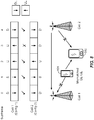
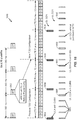
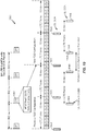
- FIG. 2 is a block diagram conceptually illustrating an example of a downlink frame structure in a telecommunications system in accordance with an aspect of the present disclosure.
- the transmission timeline for the downlink may be partitioned into units of radio frames.
- Each radio frame may have a predetermined duration (e.g ., 10 milliseconds (ms)) and may be partitioned into 10 sub-frames with indices of 0 through 9.
- Each sub-frame may include two slots.
- Each radio frame may thus include 20 slots with indices of 0 through 19.
- Each slot may include L symbol periods, e.g., 7 symbol periods for a normal cyclic prefix (as shown in FIG. 2 ) or 6 symbol periods for an extended cyclic prefix (not shown).
- the 2L symbol periods in each sub-frame may be assigned indices of 0 through 2L-1.
- the available time frequency resources may be partitioned into resource blocks. Each resource block may cover N subcarriers ( e.g ., 12 subcarriers) in one slot.
- an eNodeB may send a primary synchronization signal (PSS) and a secondary synchronization signal (SSS) for each cell in the coverage area of the eNodeB.
- the primary synchronization signal (PSS) and secondary synchronization signal (SSS) may be sent in symbol periods 6 and 5, respectively, in each of sub-frames 0 and 5 of each radio frame with the normal cyclic prefix, as shown in FIG. 2 .
- the synchronization signals may be used by UEs for cell detection and acquisition.
- the eNodeB may send system information in a Physical Broadcast Channel (PBCH) in symbol periods 0 to 3 of slot 1 of subframe 0.
- PBCH Physical Broadcast Channel
- the eNodeB may send information in a Physical Control Format Indicator Channel (PCFICH) in only a portion of the first symbol period of each sub-frame, although depicted in the entire first symbol period in FIG. 2 .
- PHICH Physical HARQ Indicator Channel
- PDCCH Physical Downlink Control Channel
- a number of resource elements may be available in each symbol period. Each resource element may cover one subcarrier in one symbol period and may be used to send one modulation symbol, which may be a real or complex value. Resource elements not used for a reference signal in each symbol period may be arranged into resource element groups (REGs). Each REG may include four resource elements in one symbol period.
- the PCFICH may occupy four REGs, which may be spaced approximately equally across frequency, in symbol period 0.
- the PHICH may occupy three REGs, which may be spread across frequency, in one or more configurable symbol periods. For example, the three REGs for the PHICH may all belong in symbol period 0 or may be spread in symbol periods 0, 1 and 2.
- the PDCCH may occupy 9, 18, 32 or 64 REGs, which may be selected from the available REGs, in the first M symbol periods. Only certain combinations of REGs may be allowed for the PDCCH.
- a UE may know the specific REGs used for the PHICH and the PCFICH.
- the UE may search different combinations of REGs for the PDCCH.
- the number of combinations to search is typically less than the number of allowed combinations for the PDCCH.
- An eNodeB may send the PDCCH to the UE in any of the combinations that the UE will search.
- a UE may be within the coverage areas of multiple eNodeBs.
- One of these eNodeBs may be selected to serve the UE.
- the serving eNodeB may be selected based on various criteria such as received power, path loss, signal-to-noise ratio (SNR), etc.
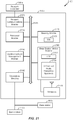
- FIG. 3 is a block diagram conceptually illustrating an exemplary eNodeB 310 and an exemplary UE 350 configured in accordance with an aspect of the present disclosure.
- the base station/eNodeB 310 and the UE 350 may be one of the base stations/eNodeBs 110 and one of the UEs 120 in FIG. 1 .
- the base station 310 may be equipped with antennas 334 1-t
- the UE 350 may be equipped with antennas 352 1-r , wherein t and r are integers greater than or equal to one.
- a base station transmit processor 320 may receive data from a base station data source 312 and control information from a base station controller/processor 340.
- the control information may be carried on the PBCH, PCFICH, PHICH, PDCCH, etc.
- the data may be carried on the PDSCH, etc.
- the base station transmit processor 320 may process (e.g ., encode and symbol map) the data and control information to obtain data symbols and control symbols, respectively.
- the base station transmit processor 320 may also generate reference symbols, e.g., for the PSS, SSS, and cell-specific reference signal (RS).
- RS cell-specific reference signal
- a UE reception processor 358 may process (e.g ., demodulate, deinterleave, and decode) the detected symbols, provide decoded data for the UE 350 to a UE data sink 360, and provide decoded control information to a UE controller/processor 380.
- the uplink signals from the UE 350 may be received by the base station antennas 334, processed by the base station modulators/demodulators 332, detected by a base station MIMO detector 336 if applicable, and further processed by a base station reception processor 338 to obtain decoded data and control information sent by the UE 350.
- the base station reception processor 338 may provide the decoded data to a base station data sink 346 and the decoded control information to the base station controller/processor 340.
- the base station controller/processor 340 and the UE controller/processor 380 may direct the operation at the base station 310 and the UE 350, respectively.
- the base station controller/processor 340 and/or other processors and modules at the base station 310 may perform or direct, e.g., the execution of various processes for the techniques described herein.
- the base station controller/processor 340 may perform or direct the operations 1100 set forth in FIG. 11 .
- the UE controller/processor 380 and/or other processors and modules at the UE 350 may also perform or direct, e.g., the execution of the operations 1300 set forth in FIG. 13 , and/or other processes for the techniques described herein.
- the base station memory 342 and the UE memory 382 may store data and program codes for the base station 310 and the UE 350, respectively.
- a scheduler 344 may schedule UEs 350 for data transmission on the downlink and/or uplink.
- the base station 310 may include means for generating a compact Downlink Control Information (DCI) for at least one of uplink (UL) or downlink (DL) transmissions, wherein the compact DCI comprises a reduced number of bits when compared to certain standard DCI formats; and means for transmitting the DCI.
- the aforementioned means may be the base station controller/processor 340, the base station memory 342, the base station transmit processor 320, the base station modulators/demodulators 332, and the base station antennas 334 configured to perform the functions recited by the aforementioned means.
- the aforementioned means may be a module or any apparatus configured to perform the functions recited by the aforementioned means.
- the UE 350 may include means for receiving compact Downlink Control Information (DCI) for at least one of uplink (UL) or downlink (DL) transmissions, wherein the DCI comprises a reduced number of bits of a standard DCI format; and means for processing the DCI.
- the aforementioned means may be the UE controller/processor 380, the UE memory 382, the UE reception processor 358, the UE MIMO detector 356, the UE modulators/demodulators 354, and the UE antennas 352 configured to perform the functions recited by the aforementioned means.
- the aforementioned means may be a module or any apparatus configured to perform the functions recited by the aforementioned means.
- the subframe format 410 may be used for an eNodeB equipped with two antennas.
- a common reference signal (CRS) may be transmitted from antennas 0 and 1 in symbol periods 0, 4, 7 and 11.
- a common reference signal (CRS) is a signal that is known a priori by a transmitter and a receiver and may also be referred to as a pilot signal.
- a common reference signal (CRS) may be a reference signal that is specific for a cell, e.g., generated based on a cell identity (ID).
- ID cell identity
- FIG. 4 for a given resource element with label Ra, a modulation symbol may be transmitted on that resource element from antenna a, and no modulation symbols may be transmitted on that resource element from other antennas.
- the subframe format 420 may be used for an eNodeB equipped with four antennas.
- a common reference signal (CRS) may be transmitted from antennas 0 and 1 in symbol periods 0, 4, 7 and 11 and from antennas 2 and 3 in symbol periods 1 and 8.
- CRS may be transmitted on evenly spaced subcarriers, which may be determined based on cell ID. Different eNodeBs may transmit their CRSs on the same or different subcarriers, depending on their cell IDs.
- resource elements not used for the CRS may be used to transmit data (e.g., traffic data, control data, and/or other data).
- E-UTRA Evolved Universal Terrestrial Radio Access
- An interlace structure may be used for each of the downlink and uplink for FDD in a communication network (e.g ., LTE network).
- a communication network e.g ., LTE network.
- Q interlaces with indices of 0 through Q - 1 may be defined, where Q may be equal to 4, 6, 8, 10, or some other value.
- Each interlace may include subframes that may be spaced apart by Q subframes.
- interlace q may include subframes q, q + Q, q + 2Q, etc., where q ⁇ (0, 1, ..., Q - 1).
- the wireless communication network may support hybrid automatic retransmission (HARQ) for data transmission on the downlink and uplink.
- HARQ hybrid automatic retransmission
- a transmitter e.g ., at an eNodeB
- a receiver e.g ., at a UE
- all transmissions of the data packet may be sent in subframes of a single interlace.
- each transmission of the data packet may be sent in any subframe.
- a UE may be located within the geographic coverage area of multiple eNodeBs.
- One of the eNodeBs may be selected to serve the UE and may be called “serving eNodeB," while other eNodeB(s) may be called “neighboring eNodeB(s)."
- the serving eNodeB may be selected based on various criteria such as received signal strength, received signal quality, pathloss, etc.
- Received signal quality may be quantified by a signal-to-noise-and-interference ratio (SINR), or a reference signal received quality (RSRQ), or some other metric.
- SINR signal-to-noise-and-interference ratio
- RSRQ reference signal received quality
- the UE may operate in a dominant interference scenario in which the UE may observe high interference from one or more neighboring eNodeBs.
- UEs may use spectrum of up to 20 MHz bandwidths for each component carrier.
- a plurality of component carriers may be allocated in a carrier aggregation configuration of up to a total of 100 MHz (5 component carriers) used for transmission and reception.
- CA carrier aggregation
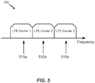
- FIG. 5 illustrates contiguous CA 500, in which multiple available component carriers 510 adjacent to each other along the frequency band are aggregated. As illustrated, component carriers 510a, 510b, and 510c are adjacent to each other along the frequency band and aggregated together in a contiguous CA configuration. While three component carriers are illustrated, more or fewer component carriers may be aggregated in a contiguous CA configuration.
- Both non-contiguous and contiguous CA may aggregate multiple component carriers to serve a single LTE-Advanced UE.
- the UE operating in a multicarrier system (also referred to as carrier aggregation) is configured to aggregate certain functions of multiple carriers, such as control and feedback functions, on the same carrier, which may be referred to as a "primary component carrier” (PCC) or "primary carrier.”
- PCC primary component carrier
- SCC secondary component carriers
- the control functions such as those provided by the optional dedicated channel (DCH), the nonscheduled grants, a physical uplink control channel (PUCCH), and/or a physical downlink control channel (PDCCH) for multiple component carriers may be carried/transmitted on a PCC of a cell.
- DCH optional dedicated channel
- PUCCH physical uplink control channel
- PDCCH physical downlink control channel
- the TDD frame structure may be a radio frame having ten subframes of equal length, with some subframes used for uplink, other subframes used for downlink, and some subframes, referred to as special subframes, used for switching from downlink to uplink.
- An LBT procedure (e.g ., a CCA) may be performed before any direction change (from uplink to downlink or downlink to uplink), after any idle time, or periodically.
- Communications in unlicensed radio frequency spectrum may include optimization of frame formats to reduce LBT overhead through an adaptation of a plurality of frame structures having different frame durations.
- time division duplex (TDD) with eIMTA allows for uplink and downlink direction changes when there is more "bursty" traffic in one direction.
- frequency division duplex (FDD) with new carrier type (NCT) which adaptively allows discontinuous transmission on the downlink on a millisecond scale when there is no traffic on a channel.
- FDD frequency division duplex
- NCT new carrier type
- small cell operation with opportunistic dormancy which may occur over a longer time scale than discontinuous transmission.
- TDD with eIMTA and other adaptive channel structure techniques can result in interference between uplink and downlink transmissions.
- a cell may adaptively select uplink-downlink configuration 5 (9 DL and 1 UL subframes) in order to accommodate a large burst of DL traffic.
- a neighboring cell may adaptively select uplink-downlink configuration 1 (6 DL and 4 UL subframes).
- a UE served by the first cell that is located near the border of the neighboring cell may attempt to receive a DL transmission in subframe 3 and may receive interference from a UE served by the neighboring cell that is transmitting an UL transmission.
- the BS of the neighboring cell attempting to receive an UL transmission in subframe 3 may receive interference from a DL transmission in the first cell.
- FIG. 8 illustrates an example of interference between uplink and downlink transmissions on multiple cells in accordance with an aspect of the present disclosure.
- An interfering transmission is illustrated in subframe 3, where Cell 1 is expecting an uplink signal and Cell 2 is transmitting on a downlink on the same frequency band. Between eNBs, such a situation may cause the receiving eNB (e.g., Cell 1) to experience severe interference from the transmitting eNB (e.g., Cell 2). Interference between UEs may also occur, for example, a UE 802 served by Cell 2 expecting a downlink transmission may experience interference from a nearby UE 804 served by Cell 1 performing an uplink transmission.
- the receiving eNB e.g., Cell 1
- the transmitting eNB e.g., Cell 2
- Interference between UEs may also occur, for example, a UE 802 served by Cell 2 expecting a downlink transmission may experience interference from a nearby UE 804 served by Cell 1 performing an uplink transmission.
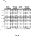
- FIG. 9 illustrates various uplink-downlink subframe configurations 900 having anchor subframes and non-anchor subframes in accordance with aspects of the present disclosure. It may be noted that the subframe configurations illustrated in FIG. 9 are identical to the configurations illustrated in FIG. 7 .
- An anchor subframe based design may be used to reduce interference.
- anchor subframes may be subframes 0-1 and subframes 5-6, as illustrated in FIG. 9 .
- FIG. 10 sets forth example operations 1000, performed, for example, by a base station, eNodeB, user equipment (UE), or other device for adapting frame structure for wireless communications using unlicensed radio frequency spectrum, in accordance with aspects of the present disclosure.
- a base station eNodeB
- UE user equipment
- Operations 1000 may optionally continue at 1006 by performing a clear channel assessment prior to communicating with a UE in one or more downlink subframes of the frame structure.
- the optional clear channel assessment may, for example, be performed based on an offset value from a frame boundary and different offset values may be assigned to give different priorities to different transmitting entities.
- operations 1000 may optionally continue by determining a transmission permission prior to communicating with an apparatus.
- Operations 1000 continue, at 1010, by communicating with the apparatus using the determined frame structure.
- operations 1000 may optionally continue by determining a subframe configuration, based at least in part on the one or more network conditions.
- Operations 1000 may optionally continue at 1014 by determining a clear channel assessment (CCA) periodicity.
- the determined CCA periodicity may be optionally based at least in part on a shortest length frame structure of the plurality of frame structures, and may be different from a CCA periodicity of the apparatus.
- operations 1000 may optionally continue by communicating an indication of the determined frame structure to the apparatus.
- the optional indication may be communicated via, for example, a clear channel assessment exempt transmission, a common control signal, a primary component carrier, and/or other techniques.
- operations 1000 may continue by receiving feedback from or transmitting feedback to the apparatus in one or more subframes of the frame structure.
- the subframes in which feedback is received or transmitted may, for example, comprise subframes having a same uplink or downlink direction as subframes in a reference subframe configuration and/or subframes that are designated as uplink subframes in each of multiple available subframe configurations.
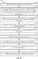
- FIG. 11 sets forth example operations 1100, performed, for example, by a base station (BS), for adapting frame structure for LTE systems using unlicensed radio frequency spectrum, in accordance with aspects of the disclosure.
- Operations 1100 may optionally begin at 1102.
- the BS may determine one or more network conditions. For example, the BS may determine that a large data burst on downlink is needed. In another example, the BS may detect interference from other BSs or UEs. In other examples, the BS may detect radar signals.
- the BS may determine a frame structure for communications, wherein the determined frame structure is one of a plurality of frame structures that can be used for communications and wherein each of the plurality of frame structures has a different frame duration.
- one frame structure may have a duration of 10 subframes, while another frame structure may have a duration of 2 subframes or a duration of 5 subframes. It may be appreciated by one of ordinary skill in the art that a frame structure can have any number of subframes.
- each of the plurality of frame structures may have either all subframes are uplink subframes or all subframes are downlink subframes, and the frame structure may be determined based on a clear channel assessment (CCA) contention process. In an aspect, the determination may be based at least in part on the one or more network conditions determined in 1102.
- CCA clear channel assessment
- Operations 1100 may optionally continue at 1106 by the BS performing a clear channel assessment prior to communicating with a UE in one or more downlink subframes of the frame structure.
- the optional clear channel assessment may, for example, be performed based on an offset value from a frame boundary and different offset values may be assigned to give different priorities to different transmitting entities.
- operations 1100 may optionally continue by the BS determining a transmission permission prior to communicating with the UE in one or more downlink subframes of the frame structure.
- the BS may communicate with a UE using the determined frame structure.
- operations 1100 may optionally continue by the BS determining a sub frame configuration, based at least in part on the one or more network conditions.
- Operations 1100 may optionally continue at 1114 by the BS determining a clear channel assessment (CCA) periodicity.
- the determined CCA periodicity may be optionally based at least in part on a shortest length frame structure of the plurality of frame structures, and may be different from a CCA periodicity of the UE.
- operations 1100 may optionally continue by the BS communicating an indication of the determined frame structure to the UE. The optional indication may be communicated via, for example, a clear channel assessment exempt transmission, a common control signal, a primary component carrier, and/or other techniques.
- operations 1100 may continue by the BS receiving feedback from the UE in one or more subframes of the frame structure.
- the subframes in which feedback is received may, for example, comprise subframes having a same uplink direction as subframes in a reference subframe configuration and/or subframes that are designated as uplink subframes in each of multiple available subframe configurations.
- the BS may determine a subframe configuration of the frame structure based at least in part on the one or more network conditions. For example, a portion of the frame may have no data traffic.
- the frame structure may be dynamically configured by the BS to have idle subframes for the portion of the frame that has no data traffic.
- the BS may configure the frame structure to have more downlink subframes in order to accommodate the downlink data traffic.
- the BS may configure the frame structure to have more uplink subframes in order to accommodate the uplink data traffic.
- the BS may perform a clear channel assessment (CCA) prior to communicating with the UE in one or more downlink subframes of the frame structure.
- CCA clear channel assessment
- the CCA may be performed to verify whether the communication channel in the unlicensed radio frequency spectrum is occupied.
- the performance of a CCA by the BS prior to communicating with the UE may comprise determining a clear channel assessment periodicity based at least in part on a shortest length frame structure of the plurality of frame structures. This may help ensure that each CCA period coincides with a possible transmission opportunity, regardless of which frame structure is actually being used.
- the BS may use a CCA periodicity of 2 ms.
- the BS may use a CCA periodicity of 5 ms.
- the BS may avoid having to change CCA periodicities when dynamically switching between different frame structures.
- performance of a CCA by the BS prior to communicating with the UE may comprise determining a clear channel assessment periodicity based at least in part on a scheduled data transmission. For example, a BS may determine that the BS will schedule a transmission to a UE in 4 ms, and determine a CCA periodicity of 4 ms.
- the BS may perform clear channel assessment with a different periodicity than UEs in the cell served by the BS. For example, a BS may perform CCA with a periodicity of ten subframes, while a served UE performs CCA with a periodicity of two subframes.
- the BS may perform a CCA based on an offset value from a frame boundary.
- the CCA may be performed at a configurable period of time (e.g., 30 microseconds before) from a frame boundary.
- different offset values may be assigned to give different priorities to different transmitting entities. For example, a smaller CCA offset value may be assigned to lower-priority transmitting entities, while a larger CCA offset value may be assigned to higher-priority transmitting entities. In the example, a higher-priority transmitting entity will determine that the channel is clear and occupy the channel before a lower-priority transmitting entity, because the larger CCA offset value causes the higher-priority entity to begin and complete the CCA earlier than the lower-priority entity.
- the UE may have a clear channel assessment (CCA) periodicity that is different from the CCA periodicity of the UE's serving base station.
- CCA periodicity may be determined by a shortest possible length of the frame structure. In the example, if the shortest frame structure length that a UE's serving BS will use is 2 milliseconds, the UE may have a clear channel assessment periodicity of 2 milliseconds.
- the UE may only be permitted to transmit in certain subframes corresponding to the UE clear channel assessment periodicity. For example, if a UE has a clear channel periodicity of four subframes, the UE will only be permitted to transmit in every fourth subframe.
- the BS may signal an indication of an adapted frame structure to the served UE.
- the indication may be signaled via at least one of: a clear channel assessment exempt transmission (CET), a common control signal, or a primary component carrier (e.g., cross-carrier signaling from a primary component carrier while using carrier aggregation).
- the indication may comprise an indication of at least one of a ratio of uplink to downlink subframes ( e.g ., seven DL to three UL subframes), a selected frame structure (e.g ., subframe configuration 4 shown in FIG.
- the frame structure or CCA configuration may be one that is preferred by the BS and, at any given time, the actual frame structure or CCA configuration in use by the BS may be different, e.g., based on changes to network conditions.
- the actual frame structure in use by a BS may be selected by the BS based on a detected transmission during a CCA.
- a UE may base CCA periodicity on the preferred frame structure or CCA configuration.
- the BS may receive feedback from the UE in certain subframes of the frame structure.
- the subframes may comprise, for example, subframes that are designated as uplink subframes in a reference subframe configuration, or subframes that are designated as uplink subframes in each of multiple available subframe configurations, similar to anchor subframes as discussed above.
- anchor subframes for an adaptive frame structure for wireless communications systems using unlicensed radio frequency spectrum is the first one or few (e.g., three) subframes of the adaptive frame structure are always designated as downlink subframes and the last one or few (e.g., two) subframes of the adaptive frame structure are always designated as uplink subframes.
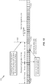
- FIG. 12 illustrates an exemplary timeline 1200 including various exemplary adaptive frame structures, in accordance with aspects of the present disclosure.
- subframes labeled 'D' are downlink subframes
- subframes labeled 'S' are special subframes wherein the transmission direction may change from downlink to uplink
- subframes labeled 'I' are idle subframes.
- a common control signal e.g., in licensed radio frequency spectrum
- the adaptive frame structure may allow for traffic load adaptation.
- a common control signal may dynamically allow idling subframes where there are no transmissions to be made, for example, where the unlicensed radio frequency spectrum is used for a supplemental downlink (SDL) and there are no transmissions to be made on the SDL, as illustrated at 1204 and 1210.
- the adaptive frame structure (and common control signal) may be configured for 10 millisecond frame duration, as illustrated at 1206.
- the adaptive frame structure may be configured with a shorter frame duration; for example, a frame length of 2 milliseconds, as illustrated at 1208.
- a CCA may be performed periodically according to the frame structure having a specified frame duration. Direction changes may be made for each frame period.
- An adaptive frame structure may also support radar detection by, for example, supporting a frame structure wherein frames are as short as or shorter than a required radar detection period.
- Radar detection may be scheduled on a region dependent time frame; for example, some regions may require radar detection every 2 milliseconds, while other regions may require radar detection every 1.5 milliseconds.
- Loading dependent adaptation (for example, additional idle time) may aid in radar detection by, for example, allowing additional radar detection during idle time.
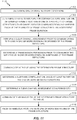
- FIG. 13 sets forth example operations 1300, performed, for example, by a user equipment (UE), for adapting frame structure for wireless communications using unlicensed radio frequency spectrum, in accordance with aspects of the present disclosure.
- the operations 1300 may be considered complementary to operations 1100, described above with reference to FIG. 11 .
- a UE may optionally begin operations 1300 at 1302, by determining one or more network conditions, wherein the network conditions may, for example, comprise network traffic conditions, interference conditions, radar detection, or other network conditions.
- the UE may determine a frame structure for communications, wherein the determined frame structure is one of a plurality of frame structures that can be used for communications and wherein each of the plurality of frame structures has a different frame duration.
- the frame structure may, for example, be determined based at least in part on the one or more network conditions.
- each of the plurality of frame structures may have either all subframes are uplink subframes or all subframes are downlink subframes, and the frame structure may be determined based on a clear channel assessment (CCA) contention process.
- the frame structure may be determined based on an indication received from a BS.
- Operations 1300 may optionally continue at 1306 by performing a clear channel assessment prior to communicating with the BS in one or more uplink subframes of the frame structure.
- the optional clear channel assessment may, for example, be performed based on an offset value from a frame boundary, and different offset values may be assigned to give different priorities to different transmitting entities.
- operations 1300 may optionally continue by determining a transmission permission prior to communicating with the BS in one or more uplink subframes of the frame structure.
- the UE may not be allowed to transmit during an upcoming time period due to communication by another network entity using the unlicensed radio frequency spectrum.
- the CCA period may be referred to as a "virtual CCA," because the UE may perform a CCA for the time period but refrain from transmitting even though the CCA indicates the channel is clear.
- the UE may not actually perform the CCA if it is not permitted to transmit.
- the UE communicates with the BS using the determined frame structure.
- Operations 1300 may optionally continue at 1314 by the UE determining a clear channel assessment (CCA) periodicity.
- the determined CCA periodicity may be optionally based at least in part on a shortest length frame structure of the plurality of frame structures, and may be different from a CCA periodicity of the BS.
- operations 1300 may continue by the UE transmitting feedback to the BS in one or more subframes of the frame structure.
- the subframes in which feedback is transmitted may, for example, comprise subframes having a same uplink direction as subframes in a reference subframe configuration and/or subframes that are designated as uplink subframes in each of multiple available subframe configurations.
- the UE may perform a clear channel assessment prior to communicating with the BS in one or more uplink subframes of the frame structure.
- a BS may schedule a UE to perform an uplink (UL) transmission on a frequency in unlicensed radio frequency spectrum.
- the UE performs a CCA on the frequency and must find the frequency to be clear before starting the UL transmission.
- the UE would not perform the UL transmission and may transmit a scheduling request (SR) or take other steps to get a new UL grant from the BS.
- SR scheduling request
- the UE may have a clear channel assessment periodicity determined by a shortest length of the frame structure.
- a UE may support frame structures wherein the length of the frames varies from 2 ms to 10 ms.
- the UE is configured to have a CCA periodicity of 2 ms, because that is the shortest length of the supported frame structures.
- the UE may only be permitted to transmit in certain subframes corresponding to the UE clear channel assessment periodicity.
- a UE may be configured with a CCA periodicity of 4 ms, and the UE is only permitted to transmit in every fourth subframe, after performing a CCA.
- the UE may determine a clear channel assessment periodicity based at least in part on a scheduled data transmission. For example, a UE may be semi-persistently scheduled to perform a data transmission in every eighth subframe, and the UE may determine a CCA periodicity of 8 ms, based on the semi-persistently scheduled data transmissions.
- the UE may perform a clear channel assessment based on an offset value from a frame boundary.
- the CCA may be performed at a configurable period of time (e.g., 20 microseconds before) from a frame boundary.
- different offset values may be assigned to give different priorities to different transmitting entities. For example, a CCA offset value of twenty microseconds may be assigned to UEs of one cell, while a CCA offset value of thirty microseconds may be assigned to a BS of a neighboring cell. In the example, the BS will determine that the channel is clear and occupy the channel ( e.g., to perform a DL transmission) before the UEs.
- the determining of a frame structure may comprise receiving signaling of an indication of the adapted frame structure by the UE.
- the indication may be received via at least one of a clear channel assessment exempt transmission, a common control signal, or from another component carrier.
- the indication may comprise an indication of at least one of a ratio of uplink to downlink subframes (e.g ., three UL subframes to seven DL subframes), a CCA priority, or a frame structure ( e.g ., three DL subframes followed by a special subframe, then an UL subframe, and then five idle subframes).
- a UE may receive a signal from the UE's serving BS that the ratio of downlink to uplink subframes in the unlicensed radio frequency spectrum will be eight to two, and the signal may be sent via a primary component carrier in the licensed radio frequency spectrum.
- the UE may transmit feedback to the BS in certain subframes of the frame structure.
- the certain subframes may comprise subframes that are designated as uplink subframes in a reference subframe configuration or subframes that are designated as uplink subframes in each of multiple available subframe configurations.
- subframe 1 may be designated as an uplink subframe in all of the available subframe configurations of a cell implementing adaptive frame structure for wireless communications using unlicensed radio frequency spectrum, and a UE may transmit feedback to the UE's serving BS in subframe 1 of every frame.
- the UE may perform uplink clear channel assessment dependent on the success of downlink clear channel assessment. For example, when multiple operators share the same spectrum, each operator's base stations may perform a DL CCA. In the example, results of the DL CCAs may determine which operator will be using the frame (e.g., if an operator's base stations' DL CCAs indicate the channel is clear, that operator may use the frame and other operators may not), and only UEs from that same operator may be allowed to perform UL CCA. Still in the example, UEs of other operators cannot use the frame because UEs of the other operators are not allowed to perform UL CCA.
- DL and UL CCA may both occur at a frame boundary, and the same transmission direction may be used during the entire frame duration. For example, if DL CCA succeeds, the entire frame may be used for DL transmission. In the example, if UL CCA succeeds, the entire frame may be used for UL transmission.
- an LBT procedure e.g., a CCA
- a CCA a duration that is short enough
- the detection of energy in the CCA may be faster than detection of a signal, and therefore performing the short enough CCA may require less overhead than detecting a signal.
- a virtual CCA may be implemented in devices implementing adaptive frame structure for wireless communications using unlicensed radio frequency spectrum.
- a virtual CCA generally refers to a CCA period that coincides with a transmission period when the device will not transmit a signal, even if the CCA indicates the channel is free (e.g., the device has no transmission permission).
- a device implementing adaptive frame structure for wireless communications using unlicensed radio frequency spectrum may be required to perform an LBT procedure (e.g ., a CCA) at every change in transmission direction, and the device may be configured to perform an LBT procedure at every change in transmission direction.
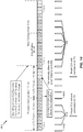
- FIG. 14 illustrates an exemplary timeline 1400 including an adaptive downlink frame structure utilizing real CCAs with permission to transmit and virtual CCAs without permission to transmit in accordance with an aspect of the present disclosure.
- a combination of real CCAs and virtual CCAs may be used to comply with regulatory requirements and allow for adaptive changes in frame structures having different frame durations.
- a real CCA may be performed by a UE or BS which has permission to transmit (e.g ., the UE or BS has performed a request to send and clear to send (RTS/CTS) signal exchange), and a virtual CCA may be performed when a UE does not have permission to transmit.
- RTS/CTS request to send and clear to send
- a real CCA or virtual CCA may be performed after a time period equal to the shortest frame duration (a "CCA period") of the frame structures used to communicate between the UE and the base station.
- a CCA period the shortest frame duration of the frame structures used to communicate between the UE and the base station.
- the CCA periodicity may be configured to 2 milliseconds (e.g ., a real CCA or virtual CCA may be performed every 2 milliseconds).
- a real CCA may be performed at the beginning of each frame, as illustrated at 1402 and 1404. Between frame beginnings, a virtual CCA 1406 may be performed every CCA period.
- a real CCA 1408 may be performed at the beginning of each frame, and virtual CCAs may not be required until the frame duration is adaptively changed to be different from the CCA period.
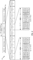
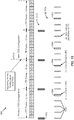
- FIG. 15 illustrates an example timeline 1500 for transmissions in a cell implementing different CCA periodicities between an eNB and a UE within an adaptive frame structure, in accordance with aspects of the present disclosure.
- This timeline may be used with carrier aggregation or for standalone use of the unlicensed radio frequency spectrum.
- CCA periodicity for the eNB may be determined by the eNB and may be more efficient than CCA periodicity for the UE.
- a CCA 1502 may be performed every 10 milliseconds ( e.g ., at the beginning of every LTE frame) to allow heavy downlink data traffic.
- CCAs with channel usage beacon signal (CUBS) 1504 there may be three different types of uplink CCAs: CCAs with channel usage beacon signal (CUBS) 1504; CCAs without CUBS 1506; and virtual CCAs 1508 when the UE does not have permission to transmit data.
- CUBS channel usage beacon signal
- a device performs a CCA and transmits a signal on the channel as soon as the device determines that the channel is clear, so that other devices performing CCAs will hear the signal and determine that the device is going to transmit on the channel.
- the UE may adapt a CCA periodicity based at least in part on a channel transmission. For example, at 1510, the UE receives a transmission indicating a new TDD configuration for frames in the unlicensed radio frequency spectrum, and adapts a new CCA periodicity for CCAs with CUBS 1504.
- the UE may adapt a CCA periodicity that matches the shortest frame duration in order to enable transmission using the frame structure having the shortest frame duration. For example, the UE may adapt a CCA periodicity equal to the shortest frame duration of the plurality of frame structures used to communicate between the eNB and the UE.
- FIG. 16 illustrates an exemplary timeline 1600 for transmissions in a cell utilizing adaptive frame structure with various signals for indicating a frame structure change, in accordance with aspects of the present disclosure.
- the preferred frame structure may be broadcast.
- a preferred uplink/downlink ratio or CCA priority may also be broadcast.
- a common control signal may be sent in the beginning of each frame, or before each frame, as at 1604, in order to indicate the frame structure of the frame.
- the common control signal may be a dynamic indication and may be multi-casted to all users associated with an operator.
- control signaling may be performed for all of the aggregated carriers on the PCC.
- a cell may use carrier aggregation with a PCC in licensed radio frequency spectrum, an SCC in licensed radio frequency spectrum, and an SCC in unlicensed radio frequency spectrum.
- the cell may schedule transmissions on the PCC and both SCCs using control signaling transmitted on the PCC.
- FIG. 17 illustrates an exemplary timeline 1700 of transmissions for a cell utilizing TDD on a primary component carrier and an adaptive frame structure for wireless communications using unlicensed radio frequency spectrum on a secondary component carrier utilized as a secondary downlink (SDL), including anchor subframes 1702 and reference subframes 1704, in accordance with aspects of the present disclosure.
- Anchor subframes in different TDD configurations may support HARQ on the SDL.
- a cell may configure an SDL using unlicensed radio frequency spectrum and perform eIMTA on a primary component carrier.
- the cell may receive HARQ ACK/NAKs, for transmissions on the SDL, in anchor subframes on the primary component carrier.
- the UEs may be configured to transmit all HARQ ACK/NAKs in the anchor subframes, so that the HARQ ACK/NAKs always encounter minimal interference.
- reference subframes from a common subset of TDD configurations e.g., UL subframes from a reference subframe configuration
- a frame in a component carrier in unlicensed radio spectrum may be used entirely for downlink transmissions, or entirely for uplink transmissions.
- a BS may perform a downlink CCA at the beginning of a frame in order to determine if the component carrier is available for downlink transmissions during the frame.
- a BS may transmit a channel usage beacon signal (CUBS) upon successful completion of the CCA. Receipt of the CUBS by UEs and other BSs may cause CCAs performed by those UEs and BSs to indicate the channel is occupied.
- CUBS channel usage beacon signal
- base stations operated by different operators may use the same frame boundaries in the unlicensed radio frequency spectrum.
- the BSs may be enabled to perform CCAs on the same time line.
- the BSs controlled by these operators may be enabled to use a frame for uplink or downlink in the same manner as neighboring BSs. This may reduce eNB-eNB, UE-UE, and eNB-UE interferences in the unlicensed radio frequency spectrum.
- different operators may engage in a contention-based protocol to determine DL or UL direction for a frame to block other devices from transmitting in the opposite direction during the frame duration.
- CCA contention may be performed at the frame boundary for both UL and DL, as well as for different operators.
- a contention process may be used to resolve which operator may use a channel in the unlicensed shared spectrum.
- the contention process may assign priorities to different operators.
- the priorities assigned to different operators may cause the different operators to perform CCA at different times (e.g., a short time offset between the CCAs performed by the different operators).
- An operator having higher priority may start a CCA earlier than other operators having lower priority, and the operator performing the earlier CCA may seize the channel ( e.g., by transmitting a CUBS) and prevent other transmissions from occurring during the frame duration.
- operator A and operator B may each operate a BS in a cell using unlicensed radio frequency spectrum, with an agreement between operator A and operator B that they will use synchronized frame boundaries and that operator A has higher priority.
- operator A may use a CCA offset of thirty microseconds
- operator B may use a CCA offset of twenty microseconds.
- operator A's BS may schedule a transmission on the unlicensed radio frequency spectrum in a frame and begin a CCA thirty microseconds before the beginning of the frame.
- operator B's BS may also schedule a transmission on the unlicensed radio frequency spectrum in the frame and begin a CCA twenty microseconds before the beginning of the frame.
- the CCA of operator A's BS will complete before the CCA of operator B's BS, and operator A's BS can seize the channel ( e.g., by transmitting a CUBS) to prevent operator B's BS from transmitting on the unlicensed radio frequency spectrum.
- a contention process may include assigning a priority to a downlink CCA and an uplink CCA.
- DL CCAs may be prioritized ahead of UL CCAs, so that a BS may perform a DL CCA and transmit a CUBS before a UE completes an UL CCA.
- the UE performing the UL CCA may receive the CUBS, which causes the UL CCA by the UE to indicate the channel is not clear.
- the priority of DL and UL CCAs may be adjusted, which may allow an UL CCA to be completed before a DL CCA is completed.
- a UE completing an UL CCA may transmit a CUBS.
- Base stations performing DL CCAs may receive the CUBS, which may cause the DL CCA by the base stations to indicate the channel is not clear.
- a core network entity may determine that network congestion has caused a backlog of UL data to accumulate at UEs served by a BS.
- the core network may cause the BS to transmit a control signal changing the priority of DL CCAs and UL CCAs, such that UL CCAs have a higher priority.
- UEs with data to transmit may complete UL CCAs and transmit a CUBS before entities performing DL CCAs (e.g., femto nodes and relay nodes), and the UEs may be able to perform UL transmissions in unlicensed radio frequency spectrum to help clear the UEs' backlog of data to be transmitted.
- entities performing DL CCAs e.g., femto nodes and relay nodes
- CCA opportunities for operators are shared among the operators on the DL with fixed sub frame boundaries.
- a UE may perform an inter-operator CCA, and if the inter-operator CCA succeeds, the UE may perform an intra-operator CCA. That is, a UE may perform an inter-operator CCA to determine that no other operators will be using the channel, and then perform an intra-operator CCA to determine that UEs and BSs associated with the UE's operator will not be using the channel.
- the UL CCA boundary can be different across operators, but dependent on the DL CCA, in that if a DL CCA succeeds, an UL CCA from the same operator may be allowed. However, if a DL CCA fails, then an UL CCA may not be allowed.
- adaptive frame structures for wireless communications using unlicensed radio frequency spectrum may be implemented with FDD implemented on licensed radio frequency spectrum and an SDL on unlicensed radio frequency spectrum.
- Such an implementation may have a variable downlink transmission length. Dynamic changes of CCA frame structure and DL transmission duration may be used for traffic adaptation, interference reduction, and radar detection.
- adaptive frame structures for wireless communications using unlicensed radio frequency spectrum may be implemented with TDD implemented on a licensed radio frequency spectrum with eIMTA and an SDL on unlicensed radio frequency spectrum.
- a reference configuration for unlicensed radio frequency spectrum SDL signaling may be defined and signaled.
- a reference configuration is a subframe configuration that is used by UEs in a cell in all frames, while the BS of the cell may switch to other subframe configurations that may be similar to the reference configuration.
- the reference configuration may be followed for operations of the unlicensed radio frequency spectrum SDL.
- the reference configuration may be updated and signaled to UEs through broadcast, group cast, or unicast signaling.
- an eNB may select UL heavy TDD configurations for the PCC, as unlicensed radio frequency spectrum provides the SDL.
- the reference configuration may be a configuration of a subset of subframes in a frame, wherein the subframes' directions are common to all TDD configurations the BS may select.
- anchor subframes of the eIMTA configuration may be used for unlicensed radio frequency spectrum SDL signaling.
- Anchor subframes may provide guaranteed signaling and may be available regardless of the selected eIMTA configuration.
- An SDL may not be directly impacted by the dynamic adaptation of the licensed carrier.
- An eNB may also use anchor subframes to support HARQ for SDL with a reduction in efficiency when compared to the technique of using reference subframes to support HARQ on SDL, described above.
- adaptive frame structures for wireless communications using unlicensed radio frequency spectrum may be implemented with carrier aggregation.
- the PCC may be in licensed radio frequency spectrum, while the unlicensed radio frequency spectrum provides one or more SCCs.
- signaling of the desired configuration of the adaptive frame structure for use in the unlicensed radio frequency spectrum may be performed in an SCC in CET signals, which may be transmitted once each 80 milliseconds.
- signaling of the desired configuration may be performed from the PCC, which may allow for adaptation in less than 80 milliseconds.
- adaptive frame structures for wireless communications using unlicensed radio frequency spectrum may be implemented with carrier aggregation, with FDD implemented on licensed radio frequency spectrum and TDD with eIMTA implemented on unlicensed radio frequency spectrum.
- two different CCA periods may be implemented for downlink transmissions and uplink transmissions on the unlicensed radio frequency spectrum operating with eIMTA.
- Downlink may use a longer CCA period for efficiency (e.g., a longer CCA period means that fewer CCAs are performed), while uplink may use a shorter CCA period to allow for fast adaptation in both directions (e.g ., CCAs are used when switching directions).
- the DL/UL CCA reconfiguration may be applied.
- opportunities for downlink CCAs and uplink CCAs occur with a period of 2 milliseconds, but some DL CCAs and UL CCAs are not performed because the corresponding DL and UL transmissions are lower priority or not allowed.
- eIMTA configuration in an area e.g., a cell or a larger region
- each operator may independently determine the eIMTA configuration that operator will use.
- a new configuration may be signaled from a PCC in order to determine the transmission direction. For example, UEs in an area may attempt an UL CCA while eNBs in the same area are attempting a DL CCA, and the UL CCA and DL CCAs may collide, such that neither UL nor DL transmissions occur.
- the eNBs may transmit a new configuration using a signal on a PCC to determine the transmission direction to be used in the area.
- a downlink/uplink traffic ratio for each eIMTA adaptation period may be signaled.
- a mapping of ratios to CCA configuration rules may be defined.
- the DL/UL CCA reconfiguration may be applied.
- eIMTA configuration may be performed per operator, and each operator may independently determine the eIMTA configuration that operator will implement.
- downlinks and uplinks may follow a 2 millisecond frame structure for LBT procedures (e.g ., CCA). Signaling of a new configuration from a PCC to determine transmission direction may be used when CCA opportunities collide, as described above.
- TDD may be implemented in a component carrier (CC) on licensed radio frequency spectrum and in a component carrier on unlicensed radio frequency spectrum.
- One or both of the TDD component carriers may implement eIMTA.
- subframes of a reference configuration or anchor subframes may be used for HARQ and control signaling of the unlicensed radio frequency spectrum TDD CC.
- the TDD CC in the licensed radio frequency spectrum may be used to handle HARQ for the unlicensed radio frequency spectrum eIMTA CC.
- both the licensed radio frequency spectrum TDD CC and unlicensed radio frequency spectrum TDD CCs may have the same configuration.
- adaptive frame structures for wireless communications using unlicensed radio frequency spectrum may also be implemented in standalone (SA) unlicensed radio frequency spectrum scenarios.
- An example SA scenario may entail an SA carrier with eIMTA in unlicensed radio frequency spectrum.
- An example SA design may be similar to CA designs as discussed above, except that signaling of an eIMTA DL/UL ratio or CCA priority on CCA exempt transmission (CET) channels may be performed once each 80 milliseconds.
- UEs may monitor the CET to adjust DL/UL ratios and/or CCA priority. Downlink/uplink CCA priority may be adjusted based on, for example, allowed or disallowed transmissions.
- a BS may transmit a signal in a CET period to raise the priority of UL transmissions when a disproportionate number of UL transmissions were disallowed in a recent time period (e.g., due to CCAs indicating the channel was occupied), or raise the priority of DL transmissions when a disproportionate number of DL transmissions were disallowed in a recent time period.
- FIG. 18 illustrates an example timeline 1800 for transmissions in a cell utilizing adaptive frame structure for wireless communications using unlicensed radio frequency spectrum implemented on standalone unlicensed radio frequency spectrum with no component carriers in licensed radio frequency spectrum.
- a BS transmits an evolved physical broadcast channel (EPBCH) during a CCA exempt transmission (CET) period 1802 signaling a selected frame structure for one or more component carriers in the unlicensed radio frequency spectrum.
- ETBCH evolved physical broadcast channel
- CET exempt transmission
- CETs may occur once per 80 milliseconds.
- a BS may use a CCA period of 10 subframes, while a UE may use a CCA period of 2 subframes where the periodicity of real CCAs by UEs (e.g., UL CCAs) may vary depending on, for example, data traffic. That is, similar to other aspects, a BS may perform a DL CCA 1804 every 10 subframes, while a UE may perform an UL CCA every 2 subframes.
- the UL CCAs may comprise UL virtual CCAs 1806, UL CCAs with CUBS 1808, and UL CCAs without CUBS 1810.
- Periodicity of each type of UL CCA may vary depending on, for example, transmission permission, and the UE performs the CCAs (e.g., a virtual CCA, a CCA with CUBS, or a CCA without CUBS) according to its configured CCA periodicity.
- the CCAs e.g., a virtual CCA, a CCA with CUBS, or a CCA without CUBS
- FIG. 19 illustrates an example timeline 1900 for transmissions in a cell utilizing adaptive frame structure for wireless communications implemented on standalone unlicensed radio frequency spectrum with eIMTA and a variable CCA period, in accordance with aspects of the present disclosure.
- a BS transmits an evolved physical broadcast channel (EPBCH) during a CCA exempt transmission (CET) period 1902 signaling a DL/UL subframe ratio or a selected frame structure for one or more component carriers in the unlicensed radio frequency spectrum.
- ETBCH evolved physical broadcast channel
- CET CCA exempt transmission
- CETs may occur once per 80 milliseconds.
- a BS may perform a DL CCA 1904 every 10 subframes.
- the UE CCA periodicity may not be fixed, as discussed above, and may be varied.
- a UE may determine when to perform an uplink operation (e.g ., based on scheduled transmissions by the UE) and may vary the UE's CCA periodicity accordingly.
- the UE is scheduled to transmit an UL transmission in the first UL subframe of each frame, and therefore uses a CCA periodicity equal to the frame duration, transmitting an UL CCA with CUBS 1906 once each 10 ms.
- the UE may adjust the CCA periodicity during transitions from one frame configuration to a different frame configuration, as illustrated at 1908.
- a UE may also adjust the UE's uplink CCA period during a transition from one TDD configuration to another.
- FIG. 20 illustrates an example of a UE 120 configured for adaptive frame structure for wireless communications using unlicensed radio frequency spectrum.
- the UE 120 may have various other configurations and may be included in or be part of a personal computer (e.g., laptop computer, netbook computer, tablet computer, etc. ), a cellular telephone, a PDA, a digital video recorder (DVR), an internet appliance, a gaming console, an e-reader, etc.
- the UE 120 may have an internal power supply (not shown), such as a small battery, to facilitate mobile operation.
- the UE 120 may be configured to implement at least some of the features and functions described above with respect to FIGS. 1-19 . For example, UE 120 may be capable of performing operations set forth in FIGS. 10 and 13 .
- the UE 120 may include a processor module 2010, a memory module 2020, a transceiver module 2040, antennas 2050, and a UE modes module 2060. Each of these components may be in communication with each other, directly or indirectly, over one or more buses 2005.
- the memory module 2020 may include random access memory (RAM) and read-only memory (ROM).
- the memory module 2020 may store computer-readable, computer-executable software (SW) code 2025 containing instructions that are configured to, when executed, cause the processor module 2010 to perform various functions described herein for using LTE-based communications in an unlicensed channel.
- SW software code 2025 containing instructions that are configured to, when executed, cause the processor module 2010 to perform various functions described herein for using LTE-based communications in an unlicensed channel.
- the software code 2025 may not be directly executable by the processor module 2010 but may be configured to cause the computer (e.g., when compiled and executed) to perform functions described herein.
- the processor module 2010 may include an intelligent hardware device, e.g. , a central processing unit (CPU), a microcontroller, an application-specific integrated circuit (ASIC), etc.
- the processor module 2010 may process information received through the transceiver module 2040 and/or to be sent to the transceiver module 2040 for transmission through the antennas 2050.
- the processor module 2010 may handle, alone or in connection with the UE modes module 2060, various aspects of using LTE-based communications in an unlicensed channel.
- the transceiver module 2040 may be configured to communicate bi-directionally with base stations (e.g ., base stations 110).
- the transceiver module 2040 may be implemented as one or more transmitter modules and one or more separate receiver modules.
- the transceiver module 2040 may support communications in a licensed radio frequency spectrum and in an unlicensed radio frequency spectrum.
- the transceiver module 2040 may include a modem configured to modulate the packets and provide the modulated packets to the antennas 2050 for transmission, and to demodulate packets received from the antennas 2050. While the UE 120 may include a single antenna, there may be embodiments in which the UE 120 includes multiple antennas 2050.
- the UE 120 may further include a communications management module 2030.
- the communications management module 2030 may manage communications with various access points.
- the communications management module 2030 may be a component of the UE 120 in communication with some or all of the other components of the UE 120 over the one or more buses 2005.
- functionality of the communications management module 2030 may be implemented as a component of the transceiver module 2040, as a computer program product, and/or as one or more controller elements of the processor module 2010.
- the UE modes module 2060 may be configured to perform and/or control some or all of the functions or aspects described in relation to FIG. 13 and related to using LTE-based communications in an unlicensed channel.
- the UE modes module 2060 may be configured to support a supplemental downlink mode, a carrier aggregation mode, and/or a standalone mode.
- the UE modes module 2060 may include an LTE module 2061 configured to handle LTE communications in licensed radio frequency spectrum and an unlicensed radio frequency module 2062 configured to handle LTE communications and communications other than LTE in unlicensed radio frequency spectrum.
- the UE modes module 2060, or portions of it, may be a processor. Moreover, some or all of the functionality of the UE modes module 2060 may be performed by the processor module 2010 and/or in connection with the processor module 2010.
- FIG. 21 a diagram 2100 is shown that illustrates a base station or eNB 110a configured for adaptive frame structure for wireless communications using unlicensed radio frequency spectrum.
- the eNodeB 110a may be configured to implement at least some of the features and functions described above with respect to FIGS. 1-19 .
- eNodeB 110a may be capable of performing operations shown in FIGS. 10-11 .
- the eNodeB 110a may include a processor module 2110, a memory module 2120, a transceiver module 2130, antennas 2140, and a base station modes module 2190.
- the base stations 110 may also include one or both of a base station communications module 2160 and a network communications module 2170. Each of these components may be in communication with each other, directly or indirectly, over one or more buses 2105.
- the memory module 2120 may include RAM and ROM.
- the memory module 2120 may also store computer-readable, computer-executable software (SW) code 2125 containing instructions that are configured to, when executed, cause the processor module 2110 to perform various functions described herein for using LTE-based communications in an unlicensed channel.
- SW software
- the software code 2125 may not be directly executable by the processor module 2110 but may be configured to cause the computer, e.g., when compiled and executed, to perform functions described herein.
- the processor module 2110 may include an intelligent hardware device, e.g., a CPU, a microcontroller, an ASIC, etc.
- the processor module 2110 may process information received through the transceiver module 2130, the base station communications module 2160, and/or the network communications module 2170.
- the processor module 2110 may also process information to be sent to the transceiver module 2130 for transmission through the antennas 2140, to the base station communications module 2160, and/or to the network communications module 2170.
- the processor module 2110 may handle, alone or in connection with the base station modes module 2190, various aspects of using LTE-based communications in an unlicensed channel.
- the transceiver module 2130 may include a modem configured to modulate the packets and provide the modulated packets to the antennas 2140 for transmission, and to demodulate packets received from the antennas 2140.
- the transceiver module 2130 may be implemented as one or more transmitter modules and one or more separate receiver modules.
- the transceiver module 2130 may support communications in a licensed radio frequency spectrum and in an unlicensed radio frequency spectrum.
- the transceiver module 2130 may be configured to communicate bi-directionally, via the antennas 2140, with one or more UEs 120.
- the eNodeB 110a may typically include multiple antennas 2140 (e.g., an antenna array).
- the eNodeB 110a may communicate with a network controller 130-a through the network communications module 2170.
- the eNodeB 110a may communicate with other base stations, such as the eNodeB 110b and the eNodeB 110c, using the base station communications module 2160.
- the eNodeB 110a may further include a communications management module 2150.
- the communications management module 2150 may manage communications with stations and/or other devices.
- the communications management module 2150 may be in communication with some or all of the other components of the eNodeB 110a via the bus or buses 2105.
- functionality of the communications management module 2150 may be implemented as a component of the transceiver module 2130, as a computer program product, and/or as one or more controller elements of the processor module 2110.
- the base station modes module 2190 may be configured to perform and/or control some or all of the functions or aspects described in FIGS. 10-11 related to using LTE-based communications in an unlicensed channel.
- the base station modes module 2190 may be configured to support a supplemental downlink mode, a carrier aggregation mode, and/or a standalone mode.
- the base station modes module 2190 may include an LTE module 2191 configured to handle LTE communications in licensed radio frequency spectrum and an unlicensed radio frequency spectrum module 2192 configured to handle LTE communications in unlicensed radio frequency spectrum.
- the base station modes module 2190, or portions of it, may be a processor. Moreover, some or all of the functionality of the base station modes module 2190 may be performed by the processor module 2110 and/or in connection with the processor module 2110.
- DSP digital signal processor
- ASIC application specific integrated circuit
- FPGA field programmable gate array
- a general-purpose processor may be a microprocessor, but in the alternative, the processor may be any conventional processor, controller, microcontroller, or state machine.
- a processor may also be implemented as a combination of computing devices, e.g., a combination of a DSP and a microprocessor, a plurality of microprocessors, one or more microprocessors in conjunction with a DSP core, or any other such configuration.
Claims (15)
- Un procédé (1000; 1100; 1300) de communications sans fil, comprenant :la détermination (1004; 1104; 1304) d'une structure de trame utilisée pour des communications, la structure de trame déterminée étant une structure de trame d'une pluralité de structures de trame qui peuvent être utilisées pour des communications, etla communication (1010; 1110; 1310) avec un appareil au moyen de la structure de trame déterminée,caractérisé en ce que chaque structure de trame de la pluralité de structures de trame possède une durée de trame différente et chaque structure de trame de la pluralité de structures de trame possède une configuration différente de sous-trames en liaison descendante.
- Le procédé (1000; 1100; 1300) selon la Revendication 1, comprenant en outre :la détermination (1002; 1102; 1302) d'une ou de plusieurs conditions de réseau, etoù la structure de trame est déterminée en fonction au moins en partie des une ou plusieurs conditions de réseau.
- Le procédé (1000; 1100) selon la Revendication 2, comprenant en outre la configuration d'une configuration de sous-trames (1012; 1112) de la structure de trame en fonction au moins en partie des une ou plusieurs conditions de réseau.
- Le procédé (1000; 1100; 1300) selon la Revendication 2, où les une ou plusieurs conditions de réseau comprennent au moins un élément parmi des conditions de trafic de réseau, des conditions de brouillage ou une détection par radar.
- Le procédé (1000; 1100; 1300) selon la Revendication 2, comprenant en outre l'exécution d'une évaluation de canal libre avant une communication avec l'appareil dans une ou plusieurs sous-trames de la structure de trame.
- Le procédé (1000; 1100; 1300) selon la Revendication 5, comprenant en outre la détermination (1014; 1114; 1314) d'une périodicité d'évaluation de canal libre, CCA, en fonction au moins en partie d'une structure de trame de longueur la plus courte de la pluralité de structures de trame.
- Le procédé (1000; 1100; 1300) selon la Revendication 5, comprenant en outre la détermination (1014; 1114; 1314) d'une périodicité d'évaluation de canal libre, CCA, où la périodicité de CCA déterminée est différente d'une périodicité de CCA de l'appareil.
- Le procédé (1000; 1100; 1300) selon la Revendication 5, comprenant en outre la détermination d'une autorisation de transmission avant une communication avec l'appareil dans une ou plusieurs sous-trames de la structure de trame.
- Le procédé (1000; 1100; 1300) selon la Revendication 5, où l'évaluation de canal libre est exécutée en fonction d'une valeur de décalage à partir d'une limite de trame, et différentes valeurs de décalage sont attribuées de façon à donner des priorités différentes à des entités de transmission différentes.
- Le procédé (1000; 1100) selon la Revendication 1, comprenant en outre la communication (1016; 1116) d'une indication de la structure de trame déterminée à l'appareil.
- Le procédé (1000; 1100) selon la Revendication 10, où l'indication est communiquée par l'intermédiaire d'au moins un élément parmi : une transmission exempte d'évaluation de canal libre, un signal de commande commun ou une porteuse de composante primaire.
- Le procédé (1000; 1100) selon la Revendication 1, comprenant en outre la réception (1018; 1118) d'informations en retour à partir de ou la transmission d'informations en retour vers l'appareil dans une ou plusieurs sous-trames de la structure de trame, où les une ou plusieurs sous-trames comprennent au moins un élément parmi :des sous-trames possédant une même direction en liaison montante ou en liaison descendante que des sous-trames dans une configuration de référence de sous-trames, etdes sous-trames qui sont désignées en tant que sous-trames d'ancrage dans chaque configuration d'une pluralité de configurations de sous-trames disponibles.
- Le procédé (1000; 1100) selon la Revendication 1, où :l'appareil comprend une station de base, etla détermination est basée sur une signalisation reçue à partir de la station de base.
- Un appareil de communications sans fil, comprenant un moyen d'exécution des opérations du procédé selon l'une quelconque des Revendications 1 et 13.
- Un support lisible par ordinateur conservant en mémoire du code exécutable par ordinateur destiné à des communications sans fil, comprenant des instructions qui, lorsqu'elles sont exécutées par un processeur, exécutent les opérations du procédé selon l'une quelconque des Revendications 1 à 13.
Applications Claiming Priority (3)
| Application Number | Priority Date | Filing Date | Title |
|---|---|---|---|
| US201361883958P | 2013-09-27 | 2013-09-27 | |
| US14/494,779 US9924509B2 (en) | 2013-09-27 | 2014-09-24 | Techniques for configuring an adaptive frame structure for wireless communications using unlicensed radio frequency spectrum |
| PCT/US2014/057340 WO2015048216A1 (fr) | 2013-09-27 | 2014-09-25 | Techniques permettant de configurer une structure de trames adaptative pour les communications sans fil utilisant le spectre de radiofréquences sans licence |
Publications (2)
| Publication Number | Publication Date |
|---|---|
| EP3050355A1 EP3050355A1 (fr) | 2016-08-03 |
| EP3050355B1 true EP3050355B1 (fr) | 2017-10-18 |
Family
ID=52740116
Family Applications (1)
| Application Number | Title | Priority Date | Filing Date |
|---|---|---|---|
| EP14783735.5A Active EP3050355B1 (fr) | 2013-09-27 | 2014-09-25 | Techniques permettant de configurer une structure de trames adaptative pour les communications sans fil utilisant le spectre de radiofréquences sans licence |
Country Status (9)
| Country | Link |
|---|---|
| US (2) | US9924509B2 (fr) |
| EP (1) | EP3050355B1 (fr) |
| JP (1) | JP6444995B2 (fr) |
| KR (1) | KR101918828B1 (fr) |
| CN (1) | CN105580426B (fr) |
| BR (1) | BR112016006676B1 (fr) |
| ES (1) | ES2656235T3 (fr) |
| HU (1) | HUE037692T2 (fr) |
| WO (1) | WO2015048216A1 (fr) |
Families Citing this family (67)
| Publication number | Priority date | Publication date | Assignee | Title |
|---|---|---|---|---|
| US9924509B2 (en) | 2013-09-27 | 2018-03-20 | Qualcomm Incorporated | Techniques for configuring an adaptive frame structure for wireless communications using unlicensed radio frequency spectrum |
| WO2015066915A1 (fr) * | 2013-11-11 | 2015-05-14 | 华为技术有限公司 | Procédé et dispositif d'utilisation de spectre sans licence |
| EP3123804B1 (fr) * | 2014-03-28 | 2019-12-04 | Intel IP Corporation | Mécanismes d'évaluation virtuelle de canal libre pour dispositifs wi-fi |
| CN105101223A (zh) * | 2014-05-16 | 2015-11-25 | 北京三星通信技术研究有限公司 | 一种在免许可频段上进行数据传输的方法和设备 |
| US9917676B2 (en) * | 2014-06-11 | 2018-03-13 | Samsung Electronics Co., Ltd. | Harq procedure and frame structure for LTE cells on unlicensed spectrum |
| US10447460B2 (en) * | 2014-09-27 | 2019-10-15 | Lg Electronics Inc. | Communication method using carrier aggregation and device for same |
| US10219256B2 (en) * | 2015-01-13 | 2019-02-26 | Qualcomm Incorporated | Control information feedback for eCC on PCell |
| CN107071915B (zh) * | 2015-01-29 | 2021-02-02 | 中兴通讯股份有限公司 | 一种数据传输方法、数据传输站点及接收端 |
| CN105992347B (zh) * | 2015-01-29 | 2021-11-12 | 北京三星通信技术研究有限公司 | 一种上行信号的发送方法、用户设备和基站 |
| CN105848181B (zh) * | 2015-01-30 | 2019-09-20 | 财团法人资讯工业策进会 | 基站、使用者装置及频道选择方法 |
| US20170245305A1 (en) * | 2015-03-10 | 2017-08-24 | Kabushiki Kaisha Toshiba | Wireless Communication Methods and Apparatus |
| US9936519B2 (en) | 2015-03-15 | 2018-04-03 | Qualcomm Incorporated | Self-contained time division duplex (TDD) subframe structure for wireless communications |
| US10075970B2 (en) | 2015-03-15 | 2018-09-11 | Qualcomm Incorporated | Mission critical data support in self-contained time division duplex (TDD) subframe structure |
| EP4007434B1 (fr) | 2015-03-17 | 2023-09-13 | Telefonaktiebolaget LM Ericsson (publ) | Planification dans un accès assisté sous licence |
| EP3823408A1 (fr) * | 2015-04-09 | 2021-05-19 | LG Electronics, Inc. | Procédé d'exécution de cca dans un système d'accès sans fil prenant en charge une bande sans licence et appareil le prenant en charge |
| EP3295727B1 (fr) * | 2015-05-14 | 2020-01-29 | Intel IP Corporation | Transmission de canal physique de commande partagé de liaison montante (pusch) sans conflit au moyen d'un accès multiple avec écoute de porteuse |
| US9814058B2 (en) | 2015-05-15 | 2017-11-07 | Qualcomm Incorporated | Scaled symbols for a self-contained time division duplex (TDD) subframe structure |
| CN106304369B (zh) * | 2015-05-15 | 2019-08-23 | 上海诺基亚贝尔股份有限公司 | 基于接入优先级的资源竞争的方法及装置 |
| US9918341B2 (en) * | 2015-05-22 | 2018-03-13 | Qualcomm Incorporated | Clear channel assessment procedure at master and slave devices |
| CN111601385A (zh) * | 2015-06-21 | 2020-08-28 | Lg 电子株式会社 | 在未授权带中发送上行链路的方法和设备 |
| US9992790B2 (en) * | 2015-07-20 | 2018-06-05 | Qualcomm Incorporated | Time division duplex (TDD) subframe structure supporting single and multiple interlace modes |
| US10251197B2 (en) * | 2015-07-23 | 2019-04-02 | Qualcomm Incorporated | Transmitting uplink control channel information when a clear channel assessment of an unlicensed carrier fails |
| CN112333692A (zh) * | 2015-07-31 | 2021-02-05 | 日本电气株式会社 | 用于执行传输的方法和设备 |
| JP2018152626A (ja) * | 2015-08-05 | 2018-09-27 | シャープ株式会社 | 端末装置、基地局装置および通信方法 |
| CN106454852A (zh) * | 2015-08-06 | 2017-02-22 | 中兴通讯股份有限公司 | 上行数据的发送方法及装置 |
| CN106455117B (zh) * | 2015-08-07 | 2021-07-23 | 中兴通讯股份有限公司 | 一种竞争接入方法和装置 |
| CN107926027B (zh) * | 2015-08-14 | 2022-05-31 | 联想创新有限公司(香港) | 在无线通信系统中基于突发的传输调度 |
| US10727979B2 (en) | 2015-08-14 | 2020-07-28 | Electronics And Telecommunications Research Institute | Operation methods of communication node in network supporting licensed and unlicensed bands |
| EP3157282A1 (fr) * | 2015-10-16 | 2017-04-19 | Panasonic Intellectual Property Corporation of America | Transmissions en liaison montante améliorées dans des cellules sans licence avec des décalages de temporisation de transmission supplémentaires |
| US10609624B2 (en) | 2015-10-16 | 2020-03-31 | Telefonaktiebolaget Lm Ericsson (Publ) | Apparatus and method for discovery reference signal aligned scheduling |
| KR102119796B1 (ko) * | 2015-10-30 | 2020-06-05 | 에스케이 텔레콤주식회사 | 비면허대역을 사용하기 위한 무선신호 전송장치 및 방법 |
| CN106658724A (zh) * | 2015-11-04 | 2017-05-10 | 中兴通讯股份有限公司 | 一种基于非授权载波的信令配置、传输方法、站点、终端 |
| US10476622B2 (en) * | 2015-11-05 | 2019-11-12 | Intel IP Corporation | Synchronization signals for license assisted access |
| EP3375239B1 (fr) * | 2015-11-09 | 2019-09-25 | Telefonaktiebolaget LM Ericsson (PUBL) | Priorisation de liaison descendante dans des systèmes lbt basés sur tdd |
| WO2017089405A1 (fr) * | 2015-11-25 | 2017-06-01 | Nokia Solutions And Networks Oy | Informations de système segmentées dans un système de communication sans fil |
| US10805953B2 (en) * | 2016-02-04 | 2020-10-13 | Ofinno, Llc | Channel access procedures in a wireless network |
| US10045376B2 (en) * | 2016-02-16 | 2018-08-07 | Mediatek Inc. | Channel access procedure and QoS provisioning for uplink LAA |
| US10292182B2 (en) | 2016-02-16 | 2019-05-14 | Hfi Innovation Inc. | Listen before talk channel access procedure for uplink LAA |
| US11319107B2 (en) * | 2016-03-07 | 2022-05-03 | Qualcomm Incorporated | Synchronization for standalone LTE broadcast |
| US11019621B2 (en) * | 2016-03-11 | 2021-05-25 | Nokia Technologies Oy | Spectrum efficiency for uplink wireless communications |
| KR102287383B1 (ko) * | 2016-03-25 | 2021-08-06 | 주식회사 윌러스표준기술연구소 | 무선 통신 시스템에서 비인가 대역으로의 상향링크 채널 액세스 방법 및 이를 위한 장치 |
| CN107295672B (zh) * | 2016-03-30 | 2023-04-07 | 中兴通讯股份有限公司 | 上行cca检测方法及装置、终端 |
| WO2018008458A2 (fr) * | 2016-07-05 | 2018-01-11 | シャープ株式会社 | Dispositif terminal, dispositif de station de base et procédé de communication |
| JP2019145870A (ja) * | 2016-07-05 | 2019-08-29 | シャープ株式会社 | 無線送信装置、無線受信装置および通信方法 |
| US11153880B2 (en) * | 2016-08-09 | 2021-10-19 | Qualcomm Incorporated | Power allocation across multiple carriers using shared and dedicated radio frequency spectrum |
| US10244399B2 (en) * | 2016-09-30 | 2019-03-26 | Qualcomm Incorporated | Signature sequence-based signaling and allocation of resources of a shared spectrum |
| CN109845388B (zh) * | 2016-10-24 | 2024-03-08 | 索尼公司 | 信息处理装置和信号发送控制方法 |
| KR20180049742A (ko) | 2016-11-03 | 2018-05-11 | 삼성전자주식회사 | 면허 대역과 비면허 대역을 이용한 통신 방법 및 그 장치 |
| US10609664B2 (en) * | 2016-11-04 | 2020-03-31 | Qualcomm Incorporated | Techniques and apparatuses for frequency division multiplexing (FDM) based medium access on shared spectrum |
| CN109417788B (zh) * | 2016-11-04 | 2023-07-18 | 华为技术有限公司 | 一种时隙调度方法及装置 |
| US10715301B2 (en) * | 2016-11-07 | 2020-07-14 | Qualcomm Incorporated | Radio-spectrum sharing (NR-SS) in frequency-division duplexing (FDD) spectrum |
| US10687358B2 (en) * | 2016-11-11 | 2020-06-16 | Qualcomm Incorporated | Opportunistic asynchronous operation for coordinated NR-SS |
| US10608755B2 (en) * | 2016-11-23 | 2020-03-31 | Aram Falsafi | Method and apparatus for wireless communication with improved performance |
| US10356626B2 (en) * | 2016-12-06 | 2019-07-16 | Qualcomm Incorporated | Opportunistic reclaiming of resources in new radio-spectrum sharing (NR-SS) |
| US10856185B2 (en) * | 2016-12-09 | 2020-12-01 | Qualcomm Incorporated | Channel reservation signals for new radio interference management |
| US10425826B2 (en) * | 2016-12-21 | 2019-09-24 | Qualcomm Incorporated | Autonomous uplink (UL)/downlink (DL) transmission in new radio-spectrum sharing (NR-SS) |
| WO2018128948A1 (fr) * | 2017-01-06 | 2018-07-12 | Intel IP Corporation | Évitement d'interférence entre nœuds |
| CN108696921A (zh) * | 2017-02-21 | 2018-10-23 | 中国科学院沈阳自动化研究所 | 基于广播前导侦听的认知传感器网络介质访问控制方法 |
| WO2018201492A1 (fr) | 2017-05-05 | 2018-11-08 | Zte Corporation | Réduction d'interférences de transmission |
| CN109039556B (zh) * | 2017-06-09 | 2023-11-07 | 华为技术有限公司 | 一种信号传输方法、相关设备及系统 |
| US11051327B2 (en) * | 2018-08-10 | 2021-06-29 | Qualcomm Incorporated | Rate-matching around CRS for NR-TDD |
| JP6957443B2 (ja) * | 2018-12-11 | 2021-11-02 | 株式会社東芝 | 通信装置、通信方法およびプログラム |
| JP7251868B2 (ja) * | 2019-07-12 | 2023-04-04 | 日本電気株式会社 | ユーザ装置及び基地局により実行される方法 |
| US11888787B2 (en) * | 2019-11-22 | 2024-01-30 | Huawei Technologies Co., Ltd. | Frame structures for wireless communication |
| EP4205439A1 (fr) * | 2020-08-31 | 2023-07-05 | Telefonaktiebolaget LM Ericsson (publ) | Détection par radar utilisant un réseau mobile |
| CN112153701B (zh) * | 2020-09-09 | 2023-11-21 | 中国联合网络通信集团有限公司 | 一种带宽使用量的确定方法和装置 |
| US11956165B2 (en) * | 2020-10-12 | 2024-04-09 | T-Mobile Usa, Inc. | Optimizing uplink band scheduling of contiguous and non-contiguous frequency range 1 (FR1) and frequency range 2 (FR2) spectrum |
Family Cites Families (28)
| Publication number | Priority date | Publication date | Assignee | Title |
|---|---|---|---|---|
| SE0302068D0 (sv) * | 2003-07-14 | 2003-07-14 | Infineon Technologies Ag | A system operable to transmit and receive messages |
| US8031583B2 (en) * | 2005-03-30 | 2011-10-04 | Motorola Mobility, Inc. | Method and apparatus for reducing round trip latency and overhead within a communication system |
| US8634333B2 (en) | 2008-05-07 | 2014-01-21 | Qualcomm Incorporated | Bundling of ACK information in a wireless communication system |
| US20100008338A1 (en) * | 2008-07-14 | 2010-01-14 | Texas Instruments Incorporated | High transmission power using shared bluetooth and wireless local area network front end module |
| WO2010056079A2 (fr) * | 2008-11-14 | 2010-05-20 | 엘지전자주식회사 | Procédé et appareil pour la transmission d'informations dans un système de transmission sans fil |
| WO2010137777A1 (fr) * | 2009-05-28 | 2010-12-02 | Lg Electronics Inc. | Appareil et procédé de détermination de structure de trame pour réduire les interférences dans un système à réutilisation de fréquence utilisant une radio cognitive |
| JP2011188451A (ja) * | 2010-03-11 | 2011-09-22 | Hitachi Kokusai Electric Inc | 通信装置 |
| US8363693B2 (en) * | 2010-04-16 | 2013-01-29 | Hitachi, Ltd. | Adaptive frequency hopping in time-slotted based wireless network |
| US8861452B2 (en) * | 2010-08-16 | 2014-10-14 | Qualcomm Incorporated | Method and apparatus for use of licensed spectrum for control channels in cognitive radio communications |
| US8804536B2 (en) * | 2010-08-16 | 2014-08-12 | Qualcomm Incorporated | Method and apparatus for facilitating sensing in cognitive radio communications |
| TWI524799B (zh) | 2010-10-12 | 2016-03-01 | 內數位專利控股公司 | 電視閒置頻段頻道選擇及網路配置以服務為基礎之方法 |
| US9420485B2 (en) * | 2011-01-04 | 2016-08-16 | Nokia Technologies Oy | Frame structure and signaling arrangement for interference aware scheduling |
| TWI615043B (zh) * | 2011-02-07 | 2018-02-11 | 內數位專利控股公司 | 在免頻譜執照中操作補充胞元方法及裝置 |
| US9693264B2 (en) * | 2011-04-18 | 2017-06-27 | Lg Electronics Inc. | Signal transmission method and device in a wireless communication system |
| GB2486926B (en) * | 2011-06-02 | 2013-10-23 | Renesas Mobile Corp | Frequency hopping in license-exempt/shared bands |
| EP2721759B1 (fr) * | 2011-06-14 | 2018-04-25 | Interdigital Patent Holdings, Inc. | Procédés, systèmes et appareil permettant de définir et d'utiliser des ressources phich pour une agrégation de porteuses |
| JP5431418B2 (ja) * | 2011-06-20 | 2014-03-05 | 日本電信電話株式会社 | 無線通信システムおよび無線通信方法 |
| WO2013006193A1 (fr) * | 2011-07-01 | 2013-01-10 | Intel Corporation | Décalage de couche dans des communications entrées multiples, sorties multiples en boucle ouverte |
| US10405306B2 (en) * | 2011-09-29 | 2019-09-03 | Qualcomm Incorporated | Half-duplex operation for low cost wireless devices |
| JP2013112372A (ja) | 2011-11-29 | 2013-06-10 | Toppan Printing Co Ltd | カートン基材表面へのフィルム貼り方法およびカートン窓貼装置及び窓付カートン |
| CN104067667A (zh) * | 2012-01-23 | 2014-09-24 | 英特尔公司 | 用于集成的多rat异类网络的网络辅助的用户关联和卸载技术 |
| US20130208587A1 (en) * | 2012-01-26 | 2013-08-15 | Interdigital Patent Holdings, Inc. | Dynamic parameter adjustment for lte coexistence |
| GB2498932B (en) | 2012-01-30 | 2013-12-18 | Renesas Mobile Corp | Method, apparatus and computer program for distributed carrier aggregation |
| US9271107B2 (en) * | 2012-01-30 | 2016-02-23 | Lg Electronics Inc. | Connection establishment method and apparatus for MTC UE |
| GB2498988B (en) | 2012-02-02 | 2014-08-06 | Broadcom Corp | Communications apparatus and methods |
| EP2901763A1 (fr) * | 2012-05-07 | 2015-08-05 | Nokia Solutions and Networks Oy | Fonctionnement dans des bandes partagées |
| US9184886B2 (en) * | 2012-08-10 | 2015-11-10 | Blackberry Limited | TD LTE secondary component carrier in unlicensed bands |
| US9924509B2 (en) | 2013-09-27 | 2018-03-20 | Qualcomm Incorporated | Techniques for configuring an adaptive frame structure for wireless communications using unlicensed radio frequency spectrum |
-
2014
- 2014-09-24 US US14/494,779 patent/US9924509B2/en active Active
- 2014-09-25 HU HUE14783735A patent/HUE037692T2/hu unknown
- 2014-09-25 BR BR112016006676-6A patent/BR112016006676B1/pt active IP Right Grant
- 2014-09-25 EP EP14783735.5A patent/EP3050355B1/fr active Active
- 2014-09-25 ES ES14783735.5T patent/ES2656235T3/es active Active
- 2014-09-25 WO PCT/US2014/057340 patent/WO2015048216A1/fr active Application Filing
- 2014-09-25 KR KR1020167011057A patent/KR101918828B1/ko active IP Right Grant
- 2014-09-25 JP JP2016517398A patent/JP6444995B2/ja active Active
- 2014-09-25 CN CN201480053268.XA patent/CN105580426B/zh active Active
-
2018
- 2018-02-06 US US15/889,454 patent/US11153869B2/en active Active
Non-Patent Citations (1)
| Title |
|---|
| None * |
Also Published As
| Publication number | Publication date |
|---|---|
| BR112016006676A2 (pt) | 2017-08-01 |
| EP3050355A1 (fr) | 2016-08-03 |
| US11153869B2 (en) | 2021-10-19 |
| KR20160062113A (ko) | 2016-06-01 |
| KR101918828B1 (ko) | 2018-11-14 |
| US20180167942A1 (en) | 2018-06-14 |
| ES2656235T3 (es) | 2018-02-26 |
| WO2015048216A1 (fr) | 2015-04-02 |
| HUE037692T2 (hu) | 2018-09-28 |
| US20150092703A1 (en) | 2015-04-02 |
| CN105580426A (zh) | 2016-05-11 |
| JP6444995B2 (ja) | 2018-12-26 |
| CN105580426B (zh) | 2019-06-18 |
| BR112016006676B1 (pt) | 2023-05-16 |
| JP2016536836A (ja) | 2016-11-24 |
| US9924509B2 (en) | 2018-03-20 |
Similar Documents
| Publication | Publication Date | Title |
|---|---|---|
| US11153869B2 (en) | Techniques for configuring an adaptive frame structure for wireless communications using unlicensed radio frequency spectrum | |
| US11140681B2 (en) | Uplink design for narrowband LTE (NB-LTE) | |
| US9001780B2 (en) | Physical layer issues related to multi-TA group support | |
| US10110363B2 (en) | Low latency in time division duplexing | |
| EP3127381B1 (fr) | Partage de puissance et rapport de marge de sécurité de puissance dans des scénarios à double connectivité | |
| US9350506B2 (en) | Aperiodic SRS for carrier aggregation | |
| US9160513B2 (en) | Method and apparatus for signaling control data of aggregated carriers | |
| US20150103782A1 (en) | Techniques for enabling asynchronous communications using unlicensed radio frequency spectrum | |
| US9131524B2 (en) | Half-duplex/full-duplex operation for TDD carrier aggregation | |
| EP2805554B1 (fr) | Procédés et appareils permettant de réaliser un accès aléatoire sur une porteuse secondaire | |
| US11290304B2 (en) | SRS carrier switching with sTTI/sPT | |
| US10952193B2 (en) | LTE-TDD carrier aggregation enhancement for half-duplex UES | |
| KR20140106505A (ko) | Tdd 캐리어 어그리게이션을 위한 하프-듀플렉스/풀-듀플렉스 동작 | |
| US20240057065A1 (en) | Handling of new radio slot aggregation in radio sidelink co-channel coexistence |
Legal Events
| Date | Code | Title | Description |
|---|---|---|---|
| PUAI | Public reference made under article 153(3) epc to a published international application that has entered the european phase |
Free format text: ORIGINAL CODE: 0009012 |
|
| 17P | Request for examination filed |
Effective date: 20160218 |
|
| AK | Designated contracting states |
Kind code of ref document: A1 Designated state(s): AL AT BE BG CH CY CZ DE DK EE ES FI FR GB GR HR HU IE IS IT LI LT LU LV MC MK MT NL NO PL PT RO RS SE SI SK SM TR |
|
| AX | Request for extension of the european patent |
Extension state: BA ME |
|
| DAX | Request for extension of the european patent (deleted) | ||
| GRAP | Despatch of communication of intention to grant a patent |
Free format text: ORIGINAL CODE: EPIDOSNIGR1 |
|
| STAA | Information on the status of an ep patent application or granted ep patent |
Free format text: STATUS: GRANT OF PATENT IS INTENDED |
|
| INTG | Intention to grant announced |
Effective date: 20170407 |
|
| RIC1 | Information provided on ipc code assigned before grant |
Ipc: H04W 28/18 20090101AFI20170324BHEP Ipc: H04W 72/04 20090101ALN20170324BHEP Ipc: H04L 5/00 20060101ALN20170324BHEP |
|
| GRAS | Grant fee paid |
Free format text: ORIGINAL CODE: EPIDOSNIGR3 |
|
| GRAA | (expected) grant |
Free format text: ORIGINAL CODE: 0009210 |
|
| STAA | Information on the status of an ep patent application or granted ep patent |
Free format text: STATUS: THE PATENT HAS BEEN GRANTED |
|
| AK | Designated contracting states |
Kind code of ref document: B1 Designated state(s): AL AT BE BG CH CY CZ DE DK EE ES FI FR GB GR HR HU IE IS IT LI LT LU LV MC MK MT NL NO PL PT RO RS SE SI SK SM TR |
|
| REG | Reference to a national code |
Ref country code: GB Ref legal event code: FG4D |
|
| REG | Reference to a national code |
Ref country code: CH Ref legal event code: EP |
|
| REG | Reference to a national code |
Ref country code: AT Ref legal event code: REF Ref document number: 938927 Country of ref document: AT Kind code of ref document: T Effective date: 20171115 Ref country code: IE Ref legal event code: FG4D |
|
| REG | Reference to a national code |
Ref country code: DE Ref legal event code: R096 Ref document number: 602014016066 Country of ref document: DE Ref country code: CH Ref legal event code: NV Representative=s name: MAUCHER JENKINS PATENTANWAELTE AND RECHTSANWAE, DE |
|
| REG | Reference to a national code |
Ref country code: NL Ref legal event code: FP |
|
| REG | Reference to a national code |
Ref country code: ES Ref legal event code: FG2A Ref document number: 2656235 Country of ref document: ES Kind code of ref document: T3 Effective date: 20180226 |
|
| REG | Reference to a national code |
Ref country code: LT Ref legal event code: MG4D |
|
| REG | Reference to a national code |
Ref country code: AT Ref legal event code: MK05 Ref document number: 938927 Country of ref document: AT Kind code of ref document: T Effective date: 20171018 |
|
| PG25 | Lapsed in a contracting state [announced via postgrant information from national office to epo] |
Ref country code: SE Free format text: LAPSE BECAUSE OF FAILURE TO SUBMIT A TRANSLATION OF THE DESCRIPTION OR TO PAY THE FEE WITHIN THE PRESCRIBED TIME-LIMIT Effective date: 20171018 Ref country code: NO Free format text: LAPSE BECAUSE OF FAILURE TO SUBMIT A TRANSLATION OF THE DESCRIPTION OR TO PAY THE FEE WITHIN THE PRESCRIBED TIME-LIMIT Effective date: 20180118 Ref country code: LT Free format text: LAPSE BECAUSE OF FAILURE TO SUBMIT A TRANSLATION OF THE DESCRIPTION OR TO PAY THE FEE WITHIN THE PRESCRIBED TIME-LIMIT Effective date: 20171018 |
|
| PG25 | Lapsed in a contracting state [announced via postgrant information from national office to epo] |
Ref country code: HR Free format text: LAPSE BECAUSE OF FAILURE TO SUBMIT A TRANSLATION OF THE DESCRIPTION OR TO PAY THE FEE WITHIN THE PRESCRIBED TIME-LIMIT Effective date: 20171018 Ref country code: IS Free format text: LAPSE BECAUSE OF FAILURE TO SUBMIT A TRANSLATION OF THE DESCRIPTION OR TO PAY THE FEE WITHIN THE PRESCRIBED TIME-LIMIT Effective date: 20180218 Ref country code: AT Free format text: LAPSE BECAUSE OF FAILURE TO SUBMIT A TRANSLATION OF THE DESCRIPTION OR TO PAY THE FEE WITHIN THE PRESCRIBED TIME-LIMIT Effective date: 20171018 Ref country code: RS Free format text: LAPSE BECAUSE OF FAILURE TO SUBMIT A TRANSLATION OF THE DESCRIPTION OR TO PAY THE FEE WITHIN THE PRESCRIBED TIME-LIMIT Effective date: 20171018 Ref country code: LV Free format text: LAPSE BECAUSE OF FAILURE TO SUBMIT A TRANSLATION OF THE DESCRIPTION OR TO PAY THE FEE WITHIN THE PRESCRIBED TIME-LIMIT Effective date: 20171018 Ref country code: GR Free format text: LAPSE BECAUSE OF FAILURE TO SUBMIT A TRANSLATION OF THE DESCRIPTION OR TO PAY THE FEE WITHIN THE PRESCRIBED TIME-LIMIT Effective date: 20180119 |
|
| REG | Reference to a national code |
Ref country code: DE Ref legal event code: R097 Ref document number: 602014016066 Country of ref document: DE |
|
| PG25 | Lapsed in a contracting state [announced via postgrant information from national office to epo] |
Ref country code: SK Free format text: LAPSE BECAUSE OF FAILURE TO SUBMIT A TRANSLATION OF THE DESCRIPTION OR TO PAY THE FEE WITHIN THE PRESCRIBED TIME-LIMIT Effective date: 20171018 Ref country code: EE Free format text: LAPSE BECAUSE OF FAILURE TO SUBMIT A TRANSLATION OF THE DESCRIPTION OR TO PAY THE FEE WITHIN THE PRESCRIBED TIME-LIMIT Effective date: 20171018 Ref country code: DK Free format text: LAPSE BECAUSE OF FAILURE TO SUBMIT A TRANSLATION OF THE DESCRIPTION OR TO PAY THE FEE WITHIN THE PRESCRIBED TIME-LIMIT Effective date: 20171018 Ref country code: CZ Free format text: LAPSE BECAUSE OF FAILURE TO SUBMIT A TRANSLATION OF THE DESCRIPTION OR TO PAY THE FEE WITHIN THE PRESCRIBED TIME-LIMIT Effective date: 20171018 |
|
| REG | Reference to a national code |
Ref country code: FR Ref legal event code: PLFP Year of fee payment: 5 |
|
| PLBE | No opposition filed within time limit |
Free format text: ORIGINAL CODE: 0009261 |
|
| STAA | Information on the status of an ep patent application or granted ep patent |
Free format text: STATUS: NO OPPOSITION FILED WITHIN TIME LIMIT |
|
| PG25 | Lapsed in a contracting state [announced via postgrant information from national office to epo] |
Ref country code: PL Free format text: LAPSE BECAUSE OF FAILURE TO SUBMIT A TRANSLATION OF THE DESCRIPTION OR TO PAY THE FEE WITHIN THE PRESCRIBED TIME-LIMIT Effective date: 20171018 Ref country code: SM Free format text: LAPSE BECAUSE OF FAILURE TO SUBMIT A TRANSLATION OF THE DESCRIPTION OR TO PAY THE FEE WITHIN THE PRESCRIBED TIME-LIMIT Effective date: 20171018 Ref country code: RO Free format text: LAPSE BECAUSE OF FAILURE TO SUBMIT A TRANSLATION OF THE DESCRIPTION OR TO PAY THE FEE WITHIN THE PRESCRIBED TIME-LIMIT Effective date: 20171018 |
|
| 26N | No opposition filed |
Effective date: 20180719 |
|
| REG | Reference to a national code |
Ref country code: HU Ref legal event code: AG4A Ref document number: E037692 Country of ref document: HU |
|
| PG25 | Lapsed in a contracting state [announced via postgrant information from national office to epo] |
Ref country code: SI Free format text: LAPSE BECAUSE OF FAILURE TO SUBMIT A TRANSLATION OF THE DESCRIPTION OR TO PAY THE FEE WITHIN THE PRESCRIBED TIME-LIMIT Effective date: 20171018 |
|
| PG25 | Lapsed in a contracting state [announced via postgrant information from national office to epo] |
Ref country code: MC Free format text: LAPSE BECAUSE OF FAILURE TO SUBMIT A TRANSLATION OF THE DESCRIPTION OR TO PAY THE FEE WITHIN THE PRESCRIBED TIME-LIMIT Effective date: 20171018 |
|
| REG | Reference to a national code |
Ref country code: BE Ref legal event code: MM Effective date: 20180930 |
|
| REG | Reference to a national code |
Ref country code: IE Ref legal event code: MM4A |
|
| PG25 | Lapsed in a contracting state [announced via postgrant information from national office to epo] |
Ref country code: IE Free format text: LAPSE BECAUSE OF NON-PAYMENT OF DUE FEES Effective date: 20180925 |
|
| PG25 | Lapsed in a contracting state [announced via postgrant information from national office to epo] |
Ref country code: BE Free format text: LAPSE BECAUSE OF NON-PAYMENT OF DUE FEES Effective date: 20180930 |
|
| PG25 | Lapsed in a contracting state [announced via postgrant information from national office to epo] |
Ref country code: MT Free format text: LAPSE BECAUSE OF NON-PAYMENT OF DUE FEES Effective date: 20180925 |
|
| PG25 | Lapsed in a contracting state [announced via postgrant information from national office to epo] |
Ref country code: TR Free format text: LAPSE BECAUSE OF FAILURE TO SUBMIT A TRANSLATION OF THE DESCRIPTION OR TO PAY THE FEE WITHIN THE PRESCRIBED TIME-LIMIT Effective date: 20171018 |
|
| PG25 | Lapsed in a contracting state [announced via postgrant information from national office to epo] |
Ref country code: PT Free format text: LAPSE BECAUSE OF FAILURE TO SUBMIT A TRANSLATION OF THE DESCRIPTION OR TO PAY THE FEE WITHIN THE PRESCRIBED TIME-LIMIT Effective date: 20171018 |
|
| PG25 | Lapsed in a contracting state [announced via postgrant information from national office to epo] |
Ref country code: CY Free format text: LAPSE BECAUSE OF FAILURE TO SUBMIT A TRANSLATION OF THE DESCRIPTION OR TO PAY THE FEE WITHIN THE PRESCRIBED TIME-LIMIT Effective date: 20171018 Ref country code: MK Free format text: LAPSE BECAUSE OF NON-PAYMENT OF DUE FEES Effective date: 20171018 |
|
| PG25 | Lapsed in a contracting state [announced via postgrant information from national office to epo] |
Ref country code: AL Free format text: LAPSE BECAUSE OF FAILURE TO SUBMIT A TRANSLATION OF THE DESCRIPTION OR TO PAY THE FEE WITHIN THE PRESCRIBED TIME-LIMIT Effective date: 20171018 |
|
| PGFP | Annual fee paid to national office [announced via postgrant information from national office to epo] |
Ref country code: BG Payment date: 20230629 Year of fee payment: 10 |
|
| PGFP | Annual fee paid to national office [announced via postgrant information from national office to epo] |
Ref country code: NL Payment date: 20230810 Year of fee payment: 10 Ref country code: LU Payment date: 20230810 Year of fee payment: 10 |
|
| PGFP | Annual fee paid to national office [announced via postgrant information from national office to epo] |
Ref country code: IT Payment date: 20230913 Year of fee payment: 10 Ref country code: GB Payment date: 20230810 Year of fee payment: 10 Ref country code: FI Payment date: 20230830 Year of fee payment: 10 |
|
| PGFP | Annual fee paid to national office [announced via postgrant information from national office to epo] |
Ref country code: HU Payment date: 20230821 Year of fee payment: 10 Ref country code: FR Payment date: 20230807 Year of fee payment: 10 Ref country code: DE Payment date: 20230425 Year of fee payment: 10 |
|
| PGFP | Annual fee paid to national office [announced via postgrant information from national office to epo] |
Ref country code: ES Payment date: 20231011 Year of fee payment: 10 |
|
| PGFP | Annual fee paid to national office [announced via postgrant information from national office to epo] |
Ref country code: CH Payment date: 20231001 Year of fee payment: 10 |