EP3050337B1 - Techniques for performing carrier sense adaptive transmission in unlicensed spectrum - Google Patents
Techniques for performing carrier sense adaptive transmission in unlicensed spectrum Download PDFInfo
- Publication number
- EP3050337B1 EP3050337B1 EP14778032.4A EP14778032A EP3050337B1 EP 3050337 B1 EP3050337 B1 EP 3050337B1 EP 14778032 A EP14778032 A EP 14778032A EP 3050337 B1 EP3050337 B1 EP 3050337B1
- Authority
- EP
- European Patent Office
- Prior art keywords
- signal
- network
- communications medium
- utilization
- snr
- Prior art date
- Legal status (The legal status is an assumption and is not a legal conclusion. Google has not performed a legal analysis and makes no representation as to the accuracy of the status listed.)
- Active
Links
- 238000000034 method Methods 0.000 title claims description 45
- 230000005540 biological transmission Effects 0.000 title claims description 41
- 238000001228 spectrum Methods 0.000 title claims description 38
- 230000003044 adaptive effect Effects 0.000 title claims description 5
- 238000004891 communication Methods 0.000 claims description 156
- 230000007774 longterm Effects 0.000 claims description 6
- 238000012545 processing Methods 0.000 description 26
- 238000005259 measurement Methods 0.000 description 25
- 230000006870 function Effects 0.000 description 20
- 230000001413 cellular effect Effects 0.000 description 19
- 238000010586 diagram Methods 0.000 description 15
- 238000005516 engineering process Methods 0.000 description 14
- 239000000969 carrier Substances 0.000 description 13
- 230000009471 action Effects 0.000 description 10
- 238000013461 design Methods 0.000 description 10
- 125000004122 cyclic group Chemical group 0.000 description 7
- 230000000116 mitigating effect Effects 0.000 description 6
- 230000011664 signaling Effects 0.000 description 6
- 238000004364 calculation method Methods 0.000 description 5
- 230000001360 synchronised effect Effects 0.000 description 5
- 230000001965 increasing effect Effects 0.000 description 4
- 238000003860 storage Methods 0.000 description 4
- 230000001351 cycling effect Effects 0.000 description 3
- 230000009849 deactivation Effects 0.000 description 3
- 238000001514 detection method Methods 0.000 description 3
- 239000013307 optical fiber Substances 0.000 description 3
- 230000000153 supplemental effect Effects 0.000 description 3
- 230000004913 activation Effects 0.000 description 2
- 230000008901 benefit Effects 0.000 description 2
- 230000015556 catabolic process Effects 0.000 description 2
- 230000003247 decreasing effect Effects 0.000 description 2
- 238000006731 degradation reaction Methods 0.000 description 2
- 238000007726 management method Methods 0.000 description 2
- 238000012544 monitoring process Methods 0.000 description 2
- 230000008520 organization Effects 0.000 description 2
- 239000002245 particle Substances 0.000 description 2
- 230000004044 response Effects 0.000 description 2
- 239000013589 supplement Substances 0.000 description 2
- 230000002776 aggregation Effects 0.000 description 1
- 238000004220 aggregation Methods 0.000 description 1
- 238000013459 approach Methods 0.000 description 1
- 239000000872 buffer Substances 0.000 description 1
- 230000010267 cellular communication Effects 0.000 description 1
- 230000008859 change Effects 0.000 description 1
- 230000001427 coherent effect Effects 0.000 description 1
- 230000001419 dependent effect Effects 0.000 description 1
- 230000002708 enhancing effect Effects 0.000 description 1
- 238000005562 fading Methods 0.000 description 1
- 239000000835 fiber Substances 0.000 description 1
- 230000003116 impacting effect Effects 0.000 description 1
- 230000002452 interceptive effect Effects 0.000 description 1
- 238000004519 manufacturing process Methods 0.000 description 1
- 238000013507 mapping Methods 0.000 description 1
- 230000007246 mechanism Effects 0.000 description 1
- 238000010295 mobile communication Methods 0.000 description 1
- 238000012986 modification Methods 0.000 description 1
- 230000004048 modification Effects 0.000 description 1
- 230000003287 optical effect Effects 0.000 description 1
- 230000000737 periodic effect Effects 0.000 description 1
- 238000013439 planning Methods 0.000 description 1
- 238000007781 pre-processing Methods 0.000 description 1
- 230000008569 process Effects 0.000 description 1
- 238000013468 resource allocation Methods 0.000 description 1
- 230000000717 retained effect Effects 0.000 description 1
- 230000009131 signaling function Effects 0.000 description 1
- 230000003595 spectral effect Effects 0.000 description 1
- 238000012546 transfer Methods 0.000 description 1
- 230000001960 triggered effect Effects 0.000 description 1
- 238000011144 upstream manufacturing Methods 0.000 description 1
- 230000000007 visual effect Effects 0.000 description 1
Images


Classifications
-
- H—ELECTRICITY
- H04—ELECTRIC COMMUNICATION TECHNIQUE
- H04W—WIRELESS COMMUNICATION NETWORKS
- H04W16/00—Network planning, e.g. coverage or traffic planning tools; Network deployment, e.g. resource partitioning or cells structures
- H04W16/14—Spectrum sharing arrangements between different networks
-
- H—ELECTRICITY
- H04—ELECTRIC COMMUNICATION TECHNIQUE
- H04L—TRANSMISSION OF DIGITAL INFORMATION, e.g. TELEGRAPHIC COMMUNICATION
- H04L43/00—Arrangements for monitoring or testing data switching networks
- H04L43/08—Monitoring or testing based on specific metrics, e.g. QoS, energy consumption or environmental parameters
- H04L43/0876—Network utilisation, e.g. volume of load or congestion level
- H04L43/0894—Packet rate
-
- H—ELECTRICITY
- H04—ELECTRIC COMMUNICATION TECHNIQUE
- H04W—WIRELESS COMMUNICATION NETWORKS
- H04W24/00—Supervisory, monitoring or testing arrangements
- H04W24/08—Testing, supervising or monitoring using real traffic
-
- H—ELECTRICITY
- H04—ELECTRIC COMMUNICATION TECHNIQUE
- H04W—WIRELESS COMMUNICATION NETWORKS
- H04W72/00—Local resource management
- H04W72/50—Allocation or scheduling criteria for wireless resources
- H04W72/54—Allocation or scheduling criteria for wireless resources based on quality criteria
- H04W72/541—Allocation or scheduling criteria for wireless resources based on quality criteria using the level of interference
-
- H—ELECTRICITY
- H04—ELECTRIC COMMUNICATION TECHNIQUE
- H04W—WIRELESS COMMUNICATION NETWORKS
- H04W74/00—Wireless channel access, e.g. scheduled or random access
- H04W74/08—Non-scheduled or contention based access, e.g. random access, ALOHA, CSMA [Carrier Sense Multiple Access]
- H04W74/0808—Non-scheduled or contention based access, e.g. random access, ALOHA, CSMA [Carrier Sense Multiple Access] using carrier sensing, e.g. as in CSMA
-
- H—ELECTRICITY
- H04—ELECTRIC COMMUNICATION TECHNIQUE
- H04W—WIRELESS COMMUNICATION NETWORKS
- H04W72/00—Local resource management
- H04W72/12—Wireless traffic scheduling
- H04W72/1215—Wireless traffic scheduling for collaboration of different radio technologies
Definitions
- aspects of this disclosure relate generally to telecommunications, and more particularly to interference mitigation and the like.
- Wireless communication systems are widely deployed to provide various types of communication content, such as voice, data, multimedia, and so on.
- Typical wireless communication systems are multiple-access systems capable of supporting communication with multiple users by sharing available system resources (e.g., bandwidth, transmit power, etc.).
- multiple-access systems include Code Division Multiple Access (CDMA) systems, Time Division Multiple Access (TDMA) systems, Frequency Division Multiple Access (FDMA) systems, Orthogonal Frequency Division Multiple Access (OFDMA) systems, and others.
- CDMA Code Division Multiple Access
- TDMA Time Division Multiple Access
- FDMA Frequency Division Multiple Access
- OFDMA Orthogonal Frequency Division Multiple Access
- 3GPP Third Generation Partnership Project
- 3GPP Long Term Evolution (LTE) Ultra Mobile Broadband
- UMB Ultra Mobile Broadband
- EV-DO Evolution Data Optimized
- IEEE Institute of Electrical and Electronics Engineers
- macro cell base stations provide connectivity and coverage to a large number of users over a certain geographical area.
- a macro network deployment is carefully planned, designed, and implemented to offer good coverage over the geographical region.
- Even such careful planning cannot fully accommodate channel characteristics such as fading, multipath, shadowing, etc., especially in indoor environments.
- Indoor users therefore often face coverage issues (e.g., call outages and quality degradation) resulting in poor user experience.
- Small cell base stations may also provide incremental capacity growth, richer user experience, and so on.
- Over-the-air interference detection is employed in some networks in an attempt to mitigate interference caused by such encroachment.
- a device may periodically monitor (e.g., sniff) for energy in the radio frequency (RF) band used by the device. Upon detection of any kind of energy, the device may back-off the RF band for a period of time.
- RF radio frequency
- LBT listen-before-talk
- the detected energy in the band might not be from a Wi-Fi device, or might not be substantial.
- the detected energy in the band may simply be adjacent channel leakage. Consequently, an LTE device may back off transmissions in the band even when there is no Wi-Fi interference.
- coexistence between LTE and Wi-Fi in the unlicensed RF band can result in LTE performance degradation to protect Wi-Fi communications.
- WO 2013/131257A1 relates to a method and apparatus for enabling coordination of transmissions of one or more operators in an unlicensed band of a communication system.
- WO 2013/112983A2 relates to methods and apparatus that may enable a wireless communication system that may be operating in a dynamic shared spectrum to coexist with other secondary users that may access the dynamic shared spectrum bands.
- WO 2013/006988A1 relates to a method and apparatus for providing a flexible time sharing mechanism on an unlicensed band of a flexible communications system.
- a method for reducing interference between networks includes decoding a signal transmitted by a first network over a communications medium using an unlicensed frequency spectrum to determine one or more parameters of a packet in the signal, estimating a level of utilization of the communications medium by the first network based at least in part on a signal strength of the signal and the one or more parameters, and adjusting a time for communicating in a second network over the communications medium using the unlicensed frequency spectrum based at least in part on the level of utilization of the communications medium by the first network.
- an apparatus for reducing interference between networks includes a signal decoding component configured to decode a signal transmitted by a first network over a communications medium using an unlicensed frequency spectrum, and a signal parameters evaluating component configured to determine one or more parameters of a packet in the signal.
- the apparatus further includes a medium utilization estimating component configured to estimate a level of utilization of the communications medium by the first network based at least in part on a signal strength of the signal and the one or more parameters, and a communication time adjusting component configured to adjust a time for communicating in a second network over the communications medium using the unlicensed frequency spectrum based at least in part on the level of utilization of the communications medium by the first network.
- another apparatus for reducing interference between networks including means for decoding a signal transmitted by a first network over a communications medium using an unlicensed frequency spectrum, and means for determining one or more parameters of a packet in the signal.
- the apparatus further includes means for estimating a level of utilization of the communications medium by the first network based at least in part on a signal strength of the signal and the one or more parameters, and means for adjusting a time for communicating in a second network over the communications medium using the unlicensed frequency spectrum based at least in part on the level of utilization of the communications medium by the first network.
- a non-transitory computer-readable medium storing computer executable code for reducing interference between networks.
- the computer-readable medium includes code for decoding a signal transmitted by a first network over a communications medium using an unlicensed frequency spectrum, and code for determining one or more parameters of a packet in the signal.
- the computer-readable medium further includes code for estimating a level of utilization of the communications medium by the first network based at least in part on a signal strength of the signal and the one or more parameters, and code for adjusting a time for communicating in a second network over the communications medium using the unlicensed frequency spectrum based at least in part on the level of utilization of the communications medium by the first network.
- the one or more aspects comprise the features hereinafter fully described and particularly pointed out in the claims.
- the following description and the annexed drawings set forth in detail certain illustrative features of the one or more aspects. These features are indicative, however, of but a few of the various ways in which the principles of various aspects may be employed, and this description is intended to include all such aspects and their equivalents.
- Described herein are various aspects related to performing carrier sense adaptive transmission at a network in an unlicensed spectrum by adjusting a time for utilizing certain resources for transmission based on estimating a medium utilization (MU) (e.g., a level of utilization of a communications medium) of at least a portion of the resources by one or more other networks.
- MU medium utilization
- transmission over the resources by the network may cause interference to communication links of one or more other networks operating over a similar radio frequency (RF) band, and thus MU of the other networks over the resources can be estimated to determine a time to back-off or refrain from using the resources for transmission to mitigate interference to the one or more other networks.
- RF radio frequency
- the MU can be estimated based at least in part on sniffing signals transmitted in the one or more other networks to determine a received signal strength of the signals and one or more parameters (e.g., packet or signal metrics, statistics).
- the one or more parameters can relate to parameters that can be decoded or obtained from the signal, such as a duration of the signal, a modulation and coding scheme (MCS) of the signal, a type of a packet within the signal, and/or the like.
- MCS modulation and coding scheme
- estimating MU based only on a received signal strength may cause back-off in cases where there is no interference (e.g., where a device or access point of the one or more other networks is not within the coverage area of the network).
- consideration and/or additional weighting can be given to signals from the one or more other networks having a certain strength and/or parameters that indicate the signals relate to a potentially interfered link in the one or more other networks. This can ensure that the time for back-off is increased to mitigate interference over the potentially interfered link and not necessarily where there is no potentially interfered link detected or where the detected link is not hindered by the interference.
- the term "communications medium” can include substantially any wired or wireless medium over which one or more network nodes can communicate using a radio transceiver (e.g., transmitter and/or receiver) to send, receive, and process signals from one another.
- a “communications medium” can include a radio frequency (RF) band, RF resources over one or more time periods, etc.
- RF radio frequency
- an "unlicensed" frequency band or spectrum can refer to a portion of RF space that is not licensed for use by one or more wireless wide area network (WWAN) technologies, but may or may not be used by other communication technologies (e.g., wireless local area network (WLAN) technologies, such as Wi-Fi).
- WWAN wireless wide area network
- WLAN wireless local area network
- a network or device that provides, adapts, or extends its operations for use in an "unlicensed" frequency band or spectrum may refer to a network or device that is configured to operate in a contention-based radio frequency band or spectrum.
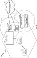
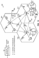
- FIG. 1 illustrates an example mixed-deployment wireless communication system, in which small cell base stations are deployed in conjunction with and to supplement the coverage of macro cell base stations.
- the term "small cell” may refer to an access point or to a corresponding coverage area of the access point, where the access point in this case has a relatively low transmit power or relatively small coverage as compared to, for example, the transmit power or coverage area of a macro network access point or macro cell.
- a macro cell may cover a relatively large geographic area, such as, but not limited to, several kilometers in radius.
- a small cell may cover a relatively small geographic area, such as, but not limited to, a home, a building, or a floor of a building.
- a small cell may include, but is not limited to, an apparatus such as a base station (BS), an access point, a femto node, a femto cell, a pico node, a micro node, a Node B, evolved Node B (eNB), home Node B (HNB) or home evolved Node B (HeNB). Therefore, the term "small cell,” as used herein, refers to a relatively low transmit power and/or a relatively small coverage area cell as compared to a macro cell.
- BS base station
- eNB evolved Node B
- HNB home Node B
- HeNB home evolved Node B
- the illustrated wireless communication system 100 is a multiple-access system that is divided into a plurality of cells 102 and configured to support communication for a number of users. Communication coverage in each of the cells 102 is provided by a corresponding base station 110, which interacts with one or more user devices 120 via DownLink (DL) and/or UpLink (UL) connections.
- DL DownLink
- UL UpLink
- the DL corresponds to communication from a base station to a user device
- the UL corresponds to communication from a user device to a base station.
- one or more of the small cell base stations 110 may include a signal processing component 112, as described further in FIGs. 8-10 .
- the terms “user device” and “base station” are not intended to be specific or otherwise limited to any particular Radio Access Technology (RAT), unless otherwise noted.
- RAT Radio Access Technology
- user devices may be any wireless communication device (e.g., a mobile phone, router, personal computer, server, etc.) used by a user to communicate over a communications network, and may be alternatively referred to in different RAT environments as an Access Terminal (AT), a Mobile Station (MS), a Subscriber Station (STA), a User Equipment (UE), etc.
- AT Access Terminal
- MS Mobile Station
- STA Subscriber Station
- UE User Equipment
- a base station may operate according to one of several RATs in communication with user devices depending on the network in which it is deployed, and may be alternatively referred to as an Access Point (AP), a Network Node, a NodeB, an evolved NodeB (eNB), etc.
- AP Access Point
- eNB evolved NodeB
- a base station may provide purely edge node signaling functions while in other systems it may provide additional control and/or network management functions.
- the different base stations 110 include an example macro cell base station 110A and two example small cell base stations 110B, 110C.
- the macro cell base station 110A is configured to provide communication coverage within a macro cell coverage area 102A, which may cover a few blocks within a neighborhood or several square miles in a rural environment.
- the small cell base stations 110B, 110C are configured to provide communication coverage within respective small cell coverage areas 102B, 102C, with varying degrees of overlap existing among the different coverage areas. In some systems, each cell may be further divided into one or more sectors (not shown).
- the user device 120A may transmit and receive messages via a wireless link with the macro cell base station 110A, the message including information related to various types of communication (e.g., voice, data, multimedia services, associated control signaling, etc.).
- the user device 120B may similarly communicate with the small cell base station 110B via another wireless link
- the user device 120C may similarly communicate with the small cell base station 110C via another wireless link.
- the user device 120C may also communicate with the macro cell base station 110A via a separate wireless link in addition to the wireless link it maintains with the small cell base station 110C.
- the macro cell base station 110A may communicate with a corresponding wide area or external network 130, via a wired link or via a wireless link, while the small cell base stations 110B, 110C may also similarly communicate with the network 130, via their own wired or wireless links.
- the small cell base stations 110B, 110C may communicate with the network 130 by way of an Internet Protocol (IP) connection, such as via a Digital Subscriber Line (DSL, e.g., including Asymmetric DSL (ADSL), High Data Rate DSL (HDSL), Very High Speed DSL (VDSL), etc.), a TV cable carrying IP traffic, a Broadband over Power Line (BPL) connection, an Optical Fiber (OF) cable, a satellite link, or some other link.
- IP Internet Protocol
- DSL Digital Subscriber Line
- ADSL Asymmetric DSL
- HDSL High Data Rate DSL
- VDSL Very High Speed DSL
- BPL Broadband over Power Line
- OF Optical Fiber
- the network 130 may comprise any type of electronically connected group of computers and/or devices, including, for example, Internet, Intranet, Local Area Networks (LANs), or Wide Area Networks (WANs).
- the connectivity to the network may be, for example, by remote modem, Ethernet (IEEE 802.3), Token Ring (IEEE 802.5), Fiber Distributed Datalink Interface (FDDI) Asynchronous Transfer Mode (ATM), Wireless Ethernet (IEEE 802.11), Bluetooth (IEEE 802.15.1), or some other connection.
- the network 130 includes network variations such as the public Internet, a private network within the Internet, a secure network within the Internet, a private network, a public network, a value-added network, an intranet, and the like.
- the network 130 may also comprise a Virtual Private Network (VPN).
- VPN Virtual Private Network
- the macro cell base station 110A and/or either or both of the small cell base stations 110B, 110C may be connected to the network 130 using any of a multitude of devices or methods. These connections may be referred to as the "backbone” or the “backhaul” of the network, and may in some implementations be used to manage and coordinate communications between the macro cell base station 110A, the small cell base station 110B, and/or the small cell base station 110C.
- the user device may be served in certain locations by macro cell base stations, at other locations by small cell base stations, and, in some scenarios, by both macro cell and small cell base stations.
- each base station 110 may operate according to one of several RATs depending on the network in which it is deployed. These networks may include, for example, Code Division Multiple Access (CDMA) networks, Time Division Multiple Access (TDMA) networks, Frequency Division Multiple Access (FDMA) networks, Orthogonal FDMA (OFDMA) networks, Single-Carrier FDMA (SC-FDMA) networks, and so on.
- CDMA Code Division Multiple Access
- TDMA Time Division Multiple Access
- FDMA Frequency Division Multiple Access
- OFDMA Orthogonal FDMA
- SC-FDMA Single-Carrier FDMA
- a CDMA network may implement a RAT such as Universal Terrestrial Radio Access (UTRA), cdma2000, etc.
- UTRA includes Wideband-CDMA (W-CDMA) and Low Chip Rate (LCR).
- cdma2000 covers IS-2000, IS-95 and IS-856 standards.
- a TDMA network may implement a RAT such as Global System for Mobile Communications (GSM).
- GSM Global System for Mobile Communications
- An OFDMA network may implement a RAT such as Evolved UTRA (E-UTRA), IEEE 802.11, IEEE 802.16, IEEE 802.20, Flash-OFDM®, etc.
- E-UTRA, E-UTRA, and GSM are part of Universal Mobile Telecommunication System (UMTS).
- UMTS Universal Mobile Telecommunication System
- LTE Long Term Evolution
- UTRA, E-UTRA, GSM, UMTS, and LTE are described in documents from an organization named "3rd Generation Partnership Project" (3GPP).
- cdma2000 is described in documents from an organization named "3rd Generation Partnership Project 2" (3GPP2). These documents are publicly available.
- FIG. 2 is a block diagram illustrating an example downlink frame structure for LTE communications.
- the base stations 110 of FIG. 1 are generally referred to as eNBs and the user devices 120 are generally referred to as UEs.
- the transmission timeline for the downlink may be partitioned into units of radio frames.
- Each radio frame may have a predetermined duration (e.g., 10 milliseconds (ms)) and may be partitioned into 10 subframes with indices of 0 through 9.
- Each sub frame may include two slots.
- Each radio frame may thus include 20 slots with indices of 0 through 19.
- Each slot may include L symbol periods, e.g., 7 symbol periods for a normal cyclic prefix (as shown in FIG.
- the 2L symbol periods in each sub frame may be assigned indices of 0 through 2L-1.
- the available time frequency resources may be partitioned into resource blocks. Each resource block may cover N subcarriers (e.g., 12 subcarriers) in one slot.
- an eNB may send a Primary Synchronization Signal (PSS) and a Secondary Synchronization Signal (SSS) for each cell in the eNB.
- PSS and SSS may be sent in symbol periods 5 and 6, respectively, in each of subframes 0 and 5 of each radio frame with the normal cyclic prefix, as shown in FIG. 2 .
- the synchronization signals may be used by UEs for cell detection and acquisition.
- the eNB may send a Physical Broadcast Channel (PBCH) in symbol periods 0 to 3 in slot 1 of sub frame 0.
- PBCH Physical Broadcast Channel
- Reference signals are transmitted during the first and fifth symbol periods of each slot when the normal cyclic prefix is used and during the first and fourth symbol periods when the extended cyclic prefix is used.
- the eNB may send a Cell-specific Reference Signal (CRS) for each cell in the eNB on all component carriers.
- the CRS may be sent in symbols 0 and 4 of each slot in case of the normal cyclic prefix, and in symbols 0 and 3 of each slot in case of the extended cyclic prefix.
- the CRS may be used by UEs for coherent demodulation of physical channels, timing and frequency tracking, Radio Link Monitoring (RLM), Reference Signal Received Power (RSRP), and Reference Signal Received Quality (RSRQ) measurements, etc.
- RLM Radio Link Monitoring
- RSRP Reference Signal Received Power
- RSRQ Reference Signal Received Quality
- the eNB may send a Physical Control Format Indicator Channel (PCFICH) in the first symbol period of each subframe, as seen in FIG. 2 .
- the eNB may send a Physical HARQ Indicator Channel (PHICH) and a Physical Downlink Control Channel (PDCCH) in the first M symbol periods of each subframe.
- the PDCCH and PHICH are also included in the first three symbol periods in the example shown in FIG. 2 .
- the PHICH may carry information to support Hybrid Automatic Repeat Request (HARQ).
- the PDCCH may carry information on resource allocation for UEs and control information for downlink channels.
- the eNB may send a Physical Downlink Shared Channel (PDSCH) in the remaining symbol periods of each subframe.
- the PDSCH may carry data for UEs scheduled for data transmission on the downlink.
- E-UTRA Evolved Universal Terrestrial Radio Access
- Physical Channels and Modulation which is publicly available.
- the eNB may send the PSS, SSS, and PBCH in the center 1.08 MHz of the system bandwidth used by the eNB.
- the eNB may send the PCFICH and PHICH across the entire system bandwidth in each symbol period in which these channels are sent.
- the eNB may send the PDCCH to groups of UEs in certain portions of the system bandwidth.
- the eNB may send the PDSCH to specific UEs in specific portions of the system bandwidth.
- the eNB may send the PSS, SSS, PBCH, PCFICH, and PHICH in a broadcast manner to all UEs, may send the PDCCH in a unicast manner to specific UEs, and may also send the PDSCH in a unicast manner to specific UEs.
- a number of resource elements may be available in each symbol period. Each resource element may cover one subcarrier in one symbol period and may be used to send one modulation symbol, which may be a real or complex value. Resource elements not used for a reference signal in each symbol period may be arranged into Resource Element Groups (REGs). Each REG may include four resource elements in one symbol period.
- the PCFICH may occupy four REGs, which may be spaced approximately equally across frequency, in symbol period 0.
- the PHICH may occupy three REGs, which may be spread across frequency, in one or more configurable symbol periods. For example, the three REGs for the PHICH may all belong in symbol period 0 or may be spread in symbol periods 0, 1, and 2.
- the PDCCH may occupy 9, 18, 32, or 64 REGs, which may be selected from the available REGs, in the first M symbol periods. Only certain combinations of REGs may be allowed for the PDCCH.
- a UE may know the specific REGs used for the PHICH and the PCFICH.
- the UE may search different combinations of REGs for the PDCCH.
- the number of combinations to search is typically less than the number of allowed combinations for the PDCCH.
- An eNB may send the PDCCH to the UE in any of the combinations that the UE will search.
- FIG. 3 is a block diagram illustrating an example uplink frame structure for LTE communications.
- the available resource blocks (which may be referred to as RBs) for the UL may be partitioned into a data section and a control section.
- the control section may be formed at the two edges of the system bandwidth and may have a configurable size.
- the resource blocks in the control section may be assigned to UEs for transmission of control information.
- the data section may include all resource blocks not included in the control section.
- the design in FIG. 3 results in the data section including contiguous subcarriers, which may allow a single UE to be assigned all of the contiguous subcarriers in the data section.
- a UE may be assigned resource blocks in the control section to transmit control information to an eNB.
- the UE may also be assigned resource blocks in the data section to transmit data to the eNB.
- the UE may transmit control information in a Physical Uplink Control Channel (PUCCH) on the assigned resource blocks in the control section.
- the UE may transmit only data or both data and control information in a Physical Uplink Shared Channel (PUSCH) on the assigned resource blocks in the data section.
- An uplink transmission may span both slots of a subframe and may hop across frequency as shown in FIG. 3 .
- cellular systems such as LTE are typically confined to one or more licensed frequency bands that have been reserved for such communications (e.g., by a government entity such as the Federal Communications Commission (FCC) in the United States).
- FCC Federal Communications Commission
- certain communication systems in particular those employing small cell base stations as in the design of FIG. 1 , have extended cellular operations into unlicensed frequency bands such as the Unlicensed National Information Infrastructure (U-NII) band used by Wireless Local Area Network (WLAN) technologies.
- U-NII Unlicensed National Information Infrastructure
- WLAN Wireless Local Area Network
- LTE on an unlicensed band may also be referred to herein as LTE / LTE-Advanced in unlicensed spectrum, or simply LTE in the surrounding context.
- the PSS, SSS, CRS, PBCH, PUCCH, and PUSCH in LTE on an unlicensed band are otherwise the same or substantially the same as in the LTE standard described in 3GPP TS 36.211, entitled "Evolved Universal Terrestrial Radio Access (E-UTRA); Physical Channels and Modulation," which is publicly available.
- E-UTRA Evolved Universal Terrestrial Radio Access
- the unlicensed spectrum may be employed by cellular systems in different ways.
- the unlicensed spectrum may be employed in a standalone configuration, with all carriers operating exclusively in an unlicensed portion of the wireless spectrum (e.g., LTE Standalone).
- the unlicensed spectrum may be employed in a manner that is supplemental to licensed band operation by utilizing one or more unlicensed carriers operating in the unlicensed portion of the wireless spectrum in conjunction with an anchor licensed carrier operating in the licensed portion of the wireless spectrum (e.g., LTE Supplemental DownLink (SDL)).
- SDL LTE Supplemental DownLink
- carrier aggregation may be employed to manage the different component carriers, with one carrier serving as the Primary Cell (PCell) for the corresponding user (e.g., an anchor licensed carrier in LTE SDL or a designated one of the unlicensed carriers in LTE Standalone) and the remaining carriers serving as respective Secondary Cells (SCells).
- PCell Primary Cell
- SCells Secondary Cells
- the PCell may provide a Frequency Division Duplexed (FDD) pair of downlink and uplink carriers (licensed or unlicensed), with each SCell providing additional downlink capacity as desired.
- FDD Frequency Division Duplexed
- U-NII 5 GHz
- Wi-Fi IEEE 802.11x WLAN technologies generally referred to as "Wi-Fi.”
- the small cell base station may include such a native RAT radio co-located with its cellular radio.
- the small cell base station may leverage the co-located radio to facilitate co-existence between the different RATs when operating on a shared unlicensed band.
- the co-located radio may be used to conduct different measurements on the unlicensed band and dynamically determine the extent to which the unlicensed band is being utilized by devices operating in accordance with the native RAT.
- the cellular radio's use of the shared unlicensed band may then be specially adapted to balance the desire for efficient cellular operation against the need for stable co-existence.
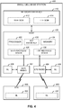
- FIG. 4 illustrates an example small cell base station with co-located radio components configured for unlicensed spectrum operation.
- the small cell base station 400 may correspond, for example, to one of the small cell base stations 110B, 110C illustrated in FIG. 1 .
- the small cell base station 400 is configured to provide a WLAN air interface (e.g., in accordance with an IEEE 802.11x protocol) in addition to a cellular air interface (e.g., in accordance with an LTE protocol).
- the small cell base station 400 is shown as including an 802.11x radio component / module (e.g., transceiver) 402 co-located with an LTE radio component / module (e.g., transceiver) 404.
- 802.11x radio component / module e.g., transceiver
- co-located may include in accordance with various aspects, one or more of, for example: components that are in the same housing; components that are hosted by the same processor; components that are within a defined distance of one another; and/or components that are connected via an interface (e.g., an Ethernet switch) where the interface meets the latency requirements of any required inter-component communication (e.g., messaging).
- an interface e.g., an Ethernet switch
- the advantages discussed herein may be achieved by adding a radio component of the native unlicensed band RAT of interest to a given cellular small cell base station without that base station necessarily providing corresponding communication access via the native unlicensed band RAT (e.g., adding a Wi-Fi chip or similar circuitry to an LTE small cell base station).
- a low functionality Wi-Fi circuit may be employed to reduce costs (e.g., a Wi-Fi receiver simply providing low-level sniffing).
- the Wi-Fi radio 402 and the LTE radio 404 may perform monitoring of one or more channels (e.g., on a corresponding carrier frequency) to perform various corresponding operating channel or environment measurements (e.g., CQI, RSSI, RSRP, or other RLM measurements) using corresponding Network / Neighbor Listen (NL) modules 406 and 408, respectively, or any other suitable component(s).
- Radios 402, 404 and/or NL modules 406 and/or 408 may include a signal processing component, as described further herein in FIGs. 8-10 , to facilitate adjusting communication times over a communication medium based at least in part on estimating a level of utilization of a communication medium by other wireless technologies, as described herein.
- the small cell base station 400 may communicate with one or more user devices via the Wi-Fi radio 402 and the LTE radio 404, illustrated as an STA 450 and a UE 460, respectively. Similar to the Wi-Fi radio 402 and the LTE radio 404, the STA 450 includes a corresponding NL module 452 and the UE 460 includes a corresponding NL module 462 for performing various operating channel or environment measurements, either independently or under the direction of the Wi-Fi radio 402 and the LTE radio 404, respectively.
- the measurements may be retained at the STA 450 and/or the UE 460, or reported to the Wi-Fi radio 402 and the LTE radio 404, respectively, with or without any pre-processing being performed by the STA 450 or the UE 460.
- FIG. 4 shows a single STA 450 and a single UE 460 for illustration purposes, it will be appreciated that the small cell base station 400 can communicate with multiple STAs and/or UEs. Additionally, while FIG. 4 illustrates one type of user device communicating with the small cell base station 400 via the Wi-Fi radio 402 (i.e., the STA 450) and another type of user device communicating with the small cell base station 400 via the LTE radio 404 (i.e., the UE 460), it will be appreciated that a single user device (e.g., a smartphone) may be capable of communicating with the small cell base station 400 via both the Wi-Fi radio 402 and the LTE radio 404, either simultaneously or at different times.
- a single user device e.g., a smartphone
- the small cell base station 400 may also include a network interface 410, which may include various components for interfacing with corresponding network entities (e.g., Self-Organizing Network (SON) nodes), such as a component for interfacing with a Wi-Fi SON 412 and/or a component for interfacing with an LTE SON 414.
- the small cell base station 400 may also include a host 420, which may include one or more general purpose controllers or processors 422 and memory 424 configured to store related data and/or instructions.
- SON Self-Organizing Network
- the host 420 may perform processing in accordance with the appropriate RAT(s) used for communication (e.g., via a Wi-Fi protocol stack 426 and/or an LTE protocol stack 428), as well as other functions for the small cell base station 400.
- the host 420 may further include a RAT interface 430 (e.g., a bus or the like) that enables the radios 402 and 404 to communicate with one another via various message exchanges.
- a RAT interface 430 e.g., a bus or the like
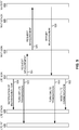
- FIG. 5 is a signaling flow diagram illustrating an example message exchange between co-located radios.
- one RAT e.g., LTE
- another RAT e.g., Wi-Fi
- FIG. 5 will be explained below with continued reference to FIG. 4 .
- the LTE SON 414 notifies the LTE stack 428 via a message 520 that a measurement gap is upcoming on the shared unlicensed band.
- the LTE SON 414 then sends a command 522 to cause the LTE radio (RF) 404 to temporarily turn off transmission on the unlicensed band, in response to which the LTE radio 404 disables the appropriate RF components for a period of time (e.g., so as to not interfere with any measurements during this time).
- RF LTE radio
- the LTE SON 414 also sends a message 524 to the co-located Wi-Fi SON 412 requesting that a measurement be taken on the unlicensed band.
- the Wi-Fi SON 412 sends a corresponding request 526 via the Wi-Fi stack 426 to the Wi-Fi radio 402, or some other suitable Wi-Fi radio component (e.g., a low cost, reduced functionality Wi-Fi receiver).
- a report 528 including the results of the measurements is sent to the LTE SON 414 via the Wi-Fi stack 426 and the Wi-Fi SON 412.
- the measurement report may include not only measurements performed by the Wi-Fi radio 402 itself, but also measurements collected by the Wi-Fi radio 402 from the STA 450.
- Wi-Fi radio 402 may include a signal processing component, as described herein in FIGs. 8-10 , to estimate a level of utilization of the communications medium by Wi-Fi signals based on additional parameters of received signals.
- the LTE SON 414 may then send a command 530 to cause the LTE radio 402 to turn back on transmission on the unlicensed band (e.g., at the end of the defined period of time).
- the information included in the measurement report may be compiled along with various LTE measurements and measurement reports.
- the small cell base station 400 may specially adapt different aspects of its cellular operations in order to manage co-existence between the different RATs.
- the LTE SON 414 may then send a message 532 that informs the LTE stack 428 how LTE communication is to be modified.
- the small cell base station 400 may select certain carriers as preferable when operating in the unlicensed band, may opportunistically enable or disable operation on those carriers, may selectively adjust the transmission power of those carriers, if necessary (e.g., periodically or intermittently in accordance with a transmission pattern), and/or take other steps to balance the desire for efficient cellular operation against the need for stable co-existence.
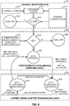
- FIG. 6 is a system-level co-existence state diagram illustrating different aspects of cellular operation that may be specially adapted to manage co-existence between different RATs operating on a shared unlicensed band.
- the techniques in this example include operations that will be referred to herein as Channel Selection (CHS) where appropriate unlicensed carriers are analyzed, Opportunistic Supplemental Downlink (OSDL) where operation on one or more corresponding SCells is configured or deconfigured, and Carrier Sense Adaptive Transmission (CSAT) where the transmission power on those SCells is adapted, if necessary, by cycling between periods of high transmission power (e.g., an ON state, as a special case) and low transmission power (e.g., an OFF state, as a special case).
- CHS Channel Selection
- OSDL Opportunistic Supplemental Downlink
- CSAT Carrier Sense Adaptive Transmission
- a channel selection algorithm may perform certain periodic or event-driven scanning procedures (e.g., initial or threshold triggered) (block 612).
- the scanning procedures may utilize, for example, one or a combination of the Wi-Fi radio 402, the LTE radio 404, the STA 450, and/or the UE 460.
- the scan results may be stored (e.g., over a sliding time window) in a corresponding database (block 614) and used to classify the different channels in terms of their potential for cellular operation (block 616). For example, a given channel may be classified, at least in part, based on whether it is a clean channel or whether it will need to be afforded some level of protection for co-channel communications.
- Various cost functions and associated metrics may be employed in the classification and related calculations.
- a corresponding SCell may be operated without concern for impacting co-channel communications (state 619).
- further processing may be utilized to reduce the impact on co-channel communications ('no' at decision 618), as described below.
- input may be received from the channel selection algorithm as well as from other sources, such as various measurements, schedulers, traffic buffers, etc. (block 622), to determine whether unlicensed operation is warranted without a clean channel being available (decision 624). For example, if there is not enough traffic to support a secondary carrier in the unlicensed band ('no' at decision 624), the corresponding SCell that supports it may be disabled (state 626). Conversely, if there is a substantial amount of traffic ('yes' at decision 624), even though a clean channel is not available, an SCell may nevertheless be constructed from one or more of the remaining carriers by invoking CSAT operation (block 630) to mitigate the potential impact on co-existence.
- the SCell may be initially enabled in a deconfigured state (state 628).
- the SCell along with one or more corresponding user devices may then be configured and activated (state 630) for normal operation.
- an associated UE may be configured and deconfigured via corresponding RRC Config / Deconfig messages to add the SCell to its active set.
- Activation and deactivation of the associated UE may be performed, for example, by using Medium Access Control (MAC) Control Element (CE) Activation / Deactivation commands.
- MAC Medium Access Control
- CE Control Element
- an RRC Deconfig message may be used to remove the SCell from the UE's active set, and return the system to the deconfigured state (state 628). If all UEs are deconfigured, OSDL may be invoked to turn the SCell off.
- the SCell may remain configured but be cycled between periods of activated operation (state 632) and periods of deactivated operation (state 634) in accordance with a (long-term) Time Division Multiplexed (TDM) communication pattern.
- TDM Time Division Multiplexed
- the SCell may operate at relatively high power (e.g., full powered ON state).
- the SCell may operate at a reduced, relatively low power (e.g., depowered OFF state).
- FIG. 7 illustrates in more detail certain aspects a CSAT communication scheme for cycling cellular operation in accordance with a long-term TDM communication pattern.
- CSAT may be selectively enabled on one or more SCells as appropriate to facilitate co-existence in unlicensed spectrum, even when a clean channel free of competing RAT operation is not available.
- SCell operation When enabled, SCell operation is cycled between CSAT ON (activated) periods and CSAT OFF (deactivated) periods within a given CSAT cycle (T CSAT ).
- One or more associated user devices may be similarly cycled between corresponding MAC activated and MAC deactivated periods.
- SCell transmission on the unlicensed band may proceed at a normal, relatively high transmission power.
- T OFF During an associated deactivated period of time T OFF , however, the SCell remains in a configured state but transmission on the unlicensed band is reduced or even fully disabled to yield the medium to a competing RAT (as well as to perform various measurements via a co-located radio of the competing RAT).
- Each of the associated CSAT parameters may be adapted based on the current signaling conditions to optimize CSAT operation.
- the CSAT pattern duty cycle i.e., T ON / T CSAT
- the relative transmission powers during activated / deactivated periods may be adapted based on the current signaling conditions to optimize CSAT operation.
- an LTE radio may adjust one or more of the CSAT parameters such that usage of the channel by the LTE radio is reduced. For example, the LTE radio may reduce its transmit duty cycle or transmit power on the channel.
- an LTE radio may adjust one or more of the CSAT parameters such that usage of the channel by the LTE radio is increased.
- the LTE radio may increase its transmit duty cycle or transmit power on the channel.
- the CSAT ON (activated) periods may be made sufficiently long (e.g., greater than or equal to about 200 msec) to provide user devices with a sufficient opportunity to perform at least one measurement during each CSAT ON (activated) period.
- a CSAT scheme as provided herein may offer several advantages for mixed RAT co-existence, particular in unlicensed spectrum. For example, by adapting communication based on signals associated with a first RAT (e.g., Wi-Fi), a second RAT (e.g., LTE) may react to utilization of a co-channel by devices that use the first RAT while refraining from reacting to extraneous interference by other devices (e.g., non-Wi-Fi devices) or adjacent channels.
- a CSAT scheme enables a device that uses one RAT to control how much protection is to be afforded to co-channel communications by devices that use another RAT by adjusting the particular parameters employed.
- such a scheme may be generally implemented without changes to the underlying RAT communication protocol.
- CSAT may be generally implemented without changing the LTE PHY or MAC layer protocols, but by simply changing the LTE software.
- the CSAT cycle may be synchronized, in whole or in part, across different small cells, at least within a given operator.
- the operator may set a minimum CSAT ON (activated) period (T ON,min ) and a minimum CSAT OFF (deactivated) period (T OFF,min ).
- the CSAT ON (activated) period durations and transmission powers may be different, but minimum deactivation times and certain channel selection measurement gaps may be synchronized.
- T ON for the CSAT cycle can be determined based at least in part on estimating a medium utilization (MU) by Wi-Fi over an associated set of resources (e.g., unlicensed RF band or spectrum). It is to be appreciated that T OFF can be determined as T ON subtracted from the duration of the CSAT cycle, which may be of fixed duration. In an example, T ON can be adapted (e.g., by an SCell, terminal, or related radio, signal processing component, etc.
- MU medium utilization
- n is a given time period (e.g., a CSAT cycle)
- ⁇ T 1 is a step value for increasing T ON where MU is less than a first threshold ( Thr 1 )
- T ON ,max is a maximum value for T ON , which may be less than the CSAT cycle duration to allow some time for Wi-Fi communications
- ⁇ T 2 is a step value for decreasing T ON where MU is greater than a second threshold ( Thr 2 )
- T ON ,min is a minimum value for T ON to
- MU can be periodically updated to include MU of previous CSAT cycles, which may be weighted.
- ⁇ ( n ) and ⁇ ( n ) can be functions of T OFF ( n ) .
- Wi-Fi performance can improve due to backing-off LTE communications over a set of resources utilized for Wi-Fi communications.
- Wi-Fi packets or related signals can be evaluated to determine not only signal strength but also one or more other parameters of the signal in determining whether to consider the packets or related signals in computing MU for Wi-Fi. Examples of considering other additional parameters are described below.
- Wi-Fi or wireless local area network (WLAN) packets can be detected based on a detected preamble, based on a detected packet structure, based on a detected long or short guard interval, etc.
- FIGs. 8-10 aspects of the present apparatus and method are depicted with reference to one or more components and one or more methods that may perform the actions or functions described herein.
- the operations described below in FIGs. 9 and 10 are presented in a particular order and/or as being performed by an example component, it should be understood that the ordering of the actions and the components performing the actions may be varied, depending on the implementation.
- the following actions or functions may be performed by a specially-programmed processor, a processor executing specially-programmed software or computer-readable media, or by any other combination of a hardware component and/or a software component capable of performing the described actions or functions.
- a component may be one of the parts that make up a system, may be hardware or software, and/or may be divided into other components.
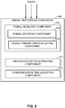
- FIG. 8 illustrates an example signal processing component 800 including a signal receiving component 810 for receiving and detecting signals of a first RAT based on parameters thereof, a medium utilization estimating component 812 for estimating a level of utilization of a communications medium by the first RAT, and a communication time adjusting component 814 for determining a communication time for a second RAT based on the estimated level of utilization of the first RAT.
- a signal receiving component 810 for receiving and detecting signals of a first RAT based on parameters thereof
- a medium utilization estimating component 812 for estimating a level of utilization of a communications medium by the first RAT
- a communication time adjusting component 814 for determining a communication time for a second RAT based on the estimated level of utilization of the first RAT.
- Wi-Fi radio 402 for receiving and detecting signals of a first RAT based on parameters thereof
- LTE radio 404 for estimating a level of utilization of a communications medium by the first RAT
- the term "component" may be one of the parts that make up a system, may be hardware or software, and may be divided into other components.
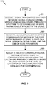
- FIG. 9 is a flow diagram illustrating an example method 900 of CSAT communication for enhancing CSAT to consider additional signal parameters in determining whether to use one or more signals in estimating MU of a communications medium by a first network using a first RAT (e.g., Wi-Fi).
- the method may be performed by an access point configured to communicate in a second network and/or using a second RAT (e.g., the small cell base stations 110B, 110C illustrated in FIG. 1 , small cell base station 400 in FIG. 4 , etc.) employing a signal processing component 800, for example.
- first and second networks are generally referred to herein, and may include networks that respectively operate on first and second RATs, as described above.
- Method 900 includes, at Block 910, decoding a signal transmitted by a first network over a communications medium using an unlicensed frequency spectrum to determine one or more parameters of a packet in the signal.
- signal receiving component 810 FIG. 8
- the one or more parameters can relate to a duration of the packet or signal, an MCS used to modulate the signal, a type of the packet or signal (e.g., data or control), and/or the like.
- the signal receiving component 810 can correspond to, can be included in, or can be employed by a receiver, a receiver portion of a transceiver or other radio, etc., such as a Wi-Fi radio 402, LTE radio 404, associated NL modules 406, 408 ( FIG. 4 ), communication device 1114 ( FIG. 11 ), etc., employed by an access point or device to receive signals of first and second networks and/or of first and second RATs (e.g., LTE and Wi-Fi).
- signal receiving component 810 may receive the signal during a T OFF period or a similar period when communications over another network or RAT are backed-off.
- signal receiving component 810 may receive the signal as a Wi-Fi signal during the T OFF period, determined according to the formulas described with respect to FIG. 4 , when communications over an LTE radio are backed-off.
- Signal decoding component 816 may decode the signal at one or more layers at which signal parameters evaluating component 818 can determine the one or more parameters. For example, signal decoding component 816 may decode the packet at a physical (PHY) layer, and signal parameters evaluating component 818 can determine a duration of the signal or packet and/or an MCS of the signal based on the PHY layer decoding. In another example, signal decoding component 816 may decode the packet additionally or alternatively at a media access control (MAC) layer, and signal parameters evaluating component 818 may determine a packet type (e.g., whether the packet is a data packet or a control packet, such as a Wi-Fi acknowledgement (ACK) or similar packet) based on the MAC layer decoding.
- MAC media access control
- Method 900 also includes, at Block 920, estimating a level of utilization of the communications medium (e.g., also referred to as a medium utilization (MU)) by the first network based at least in part on a signal strength of the signal and the one or more parameters.
- signal processing component 800 includes a medium utilization estimating component 812 for estimating the level of utilization of the communications medium.
- signal parameters evaluating component 818 can determine the signal strength as a received signal strength indicator (RSSI) of the signal received from the first network (e.g., via the receiver of the first network) or a similar measurement of received signal power. Using the one or more parameters in conjunction with the signal strength can result in a more accurate determination of the MU of the first network.
- RSSI received signal strength indicator
- some received signals may not relate to the first network or may relate to signals that may not be interfered by other communications over the communications medium.
- additionally determining the one or more parameters of the decoded signal provides additional information regarding the received signal to facilitate determining whether the signal or related packet would be interfered by communications over the communications medium or its related resources (e.g., RF resources).
- this information is used in estimating the MU of the first network by determining whether to include the signal in estimating the MU (e.g., using the formula above) and/or in determining a weight to apply to a duration of the signal in estimating the MU, as described further herein.
- Method 900 also includes, at Block 930, adjusting a time for communicating in a second network over the communications medium using the unlicensed frequency spectrum based at least in part on the level of utilization of the communications medium by the first network.
- Signal processing component 800 includes a communication time adjusting component 814 for adjusting the time for communicating in the second network (e.g., using a second RAT). For example, this includes adjusting a duty cycle for communicating over at least a portion of the set of resources in the second network (e.g., using a second RAT) based on determining the MU of the first network (e.g., that uses a first RAT).
- communication time adjusting component 814 can adjust the duty cycle by increasing or decreasing the duty cycle by a step value where the MU is less than a first threshold or greater than a second threshold (e.g., using the formulas described above in reference to FIG. 4 ).
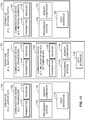
- Blocks 910 and 920 of FIG. 9 may include one or more or a portion of the Blocks described in FIG. 10 .
- an RSSI of a signal transmitted in a first network can be determined.
- signal receiving component 810 can receive the signal from one or more devices communicating in the first network (e.g., using a first RAT), and signal parameters evaluating component 818 can determine the RSSI of the signal.
- a co-located receiver of a first network can be used to obtain the first network signals (e.g., an LTE AP can include a co-located Wi-Fi radio for obtaining Wi-Fi signals) during a T OFF or similar back-off period where transmissions are not occurring (e.g., at the LTE AP).
- the first network signals e.g., an LTE AP can include a co-located Wi-Fi radio for obtaining Wi-Fi signals
- Method 1000 also includes, at Block 1020, decoding, based on the RSSI, the signal to determine a duration, MCS, or type of packet related to the signal.
- signal decoding component 816 can decode the signal at a PHY, MAC, or other layer, and signal parameters evaluating component 818 can determine the duration, MCS, or type of packet related to the signal.
- signal decoding component 816 may decode the signal (e.g., at Block 1020) based on the RSSI, such that if the signal is over a first threshold RSSI, the signal need not be decoded, and medium utilization estimating component 812 can use the signal in estimating the MU (or not use the signal) based on the RSSI and regardless of the other signal parameters.
- RSSI in an example, it can be assumed that communications over the resources would interfere with such signals, and these signals are used in estimating MU of the first network.
- Method 1000 also optionally includes, at Block 1030, determining whether to use the signal in estimating the medium utilization based on the RSSI and the duration, MCS, or type of packet.
- medium utilization estimating component 812 can determine whether to use the signal based on various parameters, as described, such as the RSSI and/or MCS of a packet determined to be a data packet, an RSSI of a packet determined to be a corresponding ACK packet, etc. where such values can be obtained.
- signal parameters evaluating component 818 can determine the MCS used by the data packet.
- Medium utilization estimating component 812 can determine an indication of downlink SNR and uplink SNR for the first network signals (e.g., the signals on the Wi-Fi link) based on the MCS, since the MCS may be selected based on the SNR (and since ACK MCS has 1:1 mapping to downlink MCS).
- RSSI of the received data signal (referred to herein as RSSI Data ) determined by signal parameters evaluating component 818 can allow medium utilization estimating component 812 to further estimate of pathloss to an AP of the first network (e.g., from an AP of the second network), and hence interference potentially caused to the AP of the first network on the downlink (e.g., interference by an LTE AP to a Wi-Fi AP) to receive ACK or uplink traffic.
- ACK or Block ACK of the uplink traffic can be received after Short Interframe Space (SIFS) duration from the data packet in Wi-Fi and can be identified by its duration.
- SIFS Short Interframe Space
- signal parameters evaluating component 818 can detect the ACK or Block ACK as a signal received after a SIFS duration relating to the received data signal, based on a duration of the signal, based on determining a source and/or destination MAC ID from a MAC header of the signal, etc.
- Signal parameters evaluating component 818 can accordingly estimate pathloss to a device of the first network (e.g., a Wi-Fi device) as well based on a determined RSSI of the ACK signal (referred to herein as RSSI ACK ).
- Medium utilization estimating component 812 can determine an indication of potential interference (e.g., by the LTE AP) to downlink traffic to the first network device.
- medium utilization estimating component 812 can estimate the drop of MCS in the first network due to potential interference by the AP of the second network (e.g., the LTE AP), and can accordingly determine whether to consider the signals in estimating medium utilization by the first network. For example, medium utilization estimating component 812, in this regard, may avoid considering signals that would not result in a threshold drop of MCS due to potential interference, which can provide a more accurate estimation of MU that would be impacted by potential interference from the AP of the second network.
- medium utilization estimating component 812 may be configured to make conservative assumptions on the DL and UL transmit power in estimating pathloss as described above (although some Wi-Fi packets may include an indicator of the transmit power used, such as beacon in AP, in which case medium utilization estimating component 812 may determine the transmit power based on that indicated in the packet). Thus, from the estimated MCS drop and conservative assumptions regarding downlink and uplink transmit power (or the power determined from the packets), medium utilization estimating component 812 may determine whether to include this packet in MU calculation and/or a weight to apply to a duration of the packet in MU calculation.
- medium utilization estimating component 812 can further determine an expected increase in Wi-Fi reuse due to transmitting over the communications medium using an LTE AP in certain durations in determining whether to include the packet in MU calculation (e.g., include the packet with the reuse is determined to be over a threshold level).
- the above considerations can be simplified to medium utilization estimating component 812 determining whether RSSI of the packet is less than a threshold, whether MCS of the packet is greater than a second threshold, and whether RSSI of a corresponding ACK packet is less than a third threshold.
- the thresholds can be configured by a network operator to the medium utilization estimating component 812 (e.g., by an operation and management (O&M) server or similar network entity).
- O&M operation and management
- the network operator may determine the thresholds to achieve a desired trade-off between LTE performance and Wi-Fi protection. Based on these determinations, medium utilization estimating component 812 can determine whether to use the corresponding Wi-Fi packets in calculating MU and/or a weight to apply to a duration of the packets in calculating MU, as described further below.
- signal parameters evaluating component 818 can determine if the type of packet is a data packet. If so, medium utilization estimating component 812 can determine if the RSSI of the data packet (RSSI Data ) is less than the first threshold RSSI (RSSI_Thr), and whether a function of the RSSI of the data packet, an RSSI of a corresponding ACK packet (RSSI ACK ), and the MCS (also referred to as f (RSSI Data , RSSI ACK , MCS DL ) herein) is greater than a second threshold ( ⁇ ). If so, medium utilization estimating component 812 can utilize the signal (e.g., or a duration thereof) in estimating MU, depending on which of the foregoing values can be obtained from the signal and/or additional signals.
- RSSI Data the RSSI of the data packet
- RSSI_Thr the first threshold RSSI
- MCS also referred to as f (RSSI Data , RSSI ACK , MCS DL ) herein
- SNR DL can be the SNR of a Wi-Fi device measured during T OFF .
- medium utilization estimating component 812 can estimate the DL SNR based on MCS DL of the received signal, such as by using MCS DL link curves.
- SIR DL can be the SIR at the Wi-Fi device where interference is caused during T ON (e.g., by the LTE AP).
- medium utilization estimating component 812 can estimate the signal level for the SIR DL using SNR DL and a conservative assumption regarding noise level.
- One example conservative assumption can be based on a 9dB noise figure and a 20MHz bandwidth (e.g., -92dBm computed as -174 + 10 * log10 (20 x 10 6 ) + 9).
- Medium utilization estimating component 812 can estimate the interference level caused to the Wi-Fi device (e.g., by the LTE AP) using RSSI ACK .
- signal parameters evaluating component 818 detecting a subsequently received ACK signal based on a determined signal type, a duration between the data signal and the ACK signal (e.g., SIFS duration), a source/destination MAC ID in the MAC header, etc., as described, and medium utilization estimating component 812 can utilize the RSSI of the signal as an indication of pathloss (e.g., to the LTE AP).
- SNR DL can be the SNR of a Wi-Fi device measured (e.g., estimated using MCS DL link curves) during T OFF , as described.
- Medium utilization estimating component 812 can determine the SINR DL at the Wi-Fi device where interference is caused during T ON (e.g., by the LTE AP) and includes noise from the Wi-Fi device.
- SNR DL / SINR DL can be the ratio of physical rate during T OFF and T ON .
- medium utilization estimating component 812 can determine f (RSSI Data , RSSI ACK , MCS DL ) as equal to RSSI ACK .
- this computation can be selected where MCS DL cannot be determined from the packet (e.g., cannot be decoded from the PHY layer of the signal).
- signal parameters evaluating component 818 may not be able to detect an ACK for the received signal (e.g., the type of packet is determined to be data and no corresponding ACK has been received). This may occur, for example, where the Wi-Fi device to which the data signal is sent by the Wi-Fi AP is outside of a cell provided by the LTE AP that utilizes the signal processing component 800 (thus the LTE AP receives signals from the Wi-Fi AP but not from the Wi-Fi device). This may also occur, for example, where another Wi-Fi device or the LTE AP cell causes interference to the Wi-Fi device transmitting ACK signals to the Wi-Fi AP.
- medium utilization estimating component 812 can determine whether to use the signal in estimating the medium utilization based on determining whether the SNR DL is additionally less than a SNR threshold. For example, medium utilization estimating component 812 can compute the SNR threshold assuming for RSSI ACK , N + 4, where N is a noise power in decibel-milliwatts (dBm), and 4dB corresponds to the minimum SNR level to decode a signal header (e.g., SIG header in 802.11a/n/ac, such as L-SIG, HT-SIG, VHT-SIG-A, etc.).
- SIG header in 802.11a/n/ac such as L-SIG, HT-SIG, VHT-SIG-A, etc.
- medium utilization estimating component 812 can compute the SNR threshold as (4 + Tx SC - Tx STA ) / (1 - 1 / ⁇ ), where Tx SC is a transmit power of the LTE AP in dBm, Tx STA is a conservative assumption on the Wi-Fi device transmit power in dBm (e.g., 15 dBm).
- signal parameters evaluating component 818 may not be able to detect data signals corresponding to received ACK packets. This may occur, for example, where the Wi-Fi AP to which the ACK is sent by the Wi-Fi device is outside of a cell provided by the LTE AP that utilizes the signal processing component 800 (thus the LTE AP receives signals from the Wi-Fi device but not the Wi-Fi AP). This may also occur, for example, where another Wi-Fi AP or the LTE AP cell causes interference to the Wi-Fi AP transmitting data signals to the Wi-Fi device.
- medium utilization estimating component 812 can determine whether to use the signal in estimating the medium utilization based on determining whether the RSSI ACK > the first threshold RSSI (RSSI Thr) for data packets, as described above.
- medium utilization estimating component 812 may also extend the duration of the signal to be the size of a data packet for the purposes of estimating MU, in one example, since an ACK packet is much shorter, though receiving the ACK may indicate similar interference to the actual data packet.
- medium utilization estimating component 812 can determine whether to use the signal in estimating the medium utilization based on the RSSI and the duration, MCS, or type of packet (e.g., at Block 1030) by determining to use the signal with a certain probability based on comparing the RSSI and the duration, MCS, type of packet, or function thereof, to multiple thresholds.
- medium utilization estimating component 812 can determine to use the signal in estimating MU using a first probability p high where RSSI Data ⁇ RSSI_Thr high , using a second probability p med where RSSI_Thr med ⁇ RSSI Data ⁇ RSSI_Thr high , using a third probability p low where RSSI_Thr low ⁇ RSSI Data ⁇ RSSI_Thr med , etc.
- Method 1000 optionally includes, at Block 1040, applying a weight to the duration of the signal based on the RSSI and the duration, MCS, or type of packet related to the signal.
- medium utilization estimating component 812 can apply a weight to the signal in estimating the MU.
- the weight can be applied using similar calculations as those described above for determining whether to use the signal in estimating the MU.
- the weight can be different based on different values for RSSI, f (RSSI Data , RSSl ACK , MCS DL ), etc.
- bins can be used to divide the packets according to different weights, where each bin has a condition related to RSSI, f (RSSI Data , RSSI ACK , MCS DL ), etc., and a corresponding weight.
- medium utilization estimating component 812 determines a signal has RSSI Data ⁇ RSSI_Thr 1 , and f 1 (RSSI Data , RSSI ACK , MCS DL ) > ⁇ 1 , medium utilization estimating component 812 can apply a first weight W1 to the duration of the signal, where RSSI_Thr 1 is a first threshold RSSI and ⁇ 1 is a first function threshold.
- medium utilization estimating component 812 determines the signal has RSSI_Thr 2 ⁇ RSSI Data ⁇ RSSI_Thr 1 and f 2 (RSSI Data , RSSI ACK , MCS DL ) > ⁇ 2
- medium utilization estimating component 812 can apply a second weight W2 to the duration of the signal, where RSSI_Thr 2 is a second RSSI threshold less than RSSI_Thr 1 , and ⁇ 2 is a second function threshold less than ⁇ 1 .
- RSSI-Thr n is a nth threshold RSSI less than RSSI_Thr n-1 , which is a (n - 1)th threshold less than RSSI_Thr 2
- ⁇ n is a nth function threshold RSSI less than ⁇ 2 .
- bins can be used to classify packets according to the relationship between RSSI and f 1 (RSSI Data , RSSI ACK , MCS DL ) and one or more thresholds, and each bin can have a corresponding weight.
- RSSI and f 1 RSSI Data , RSSI ACK , MCS DL
- f n RSSI Data , RSSI ACK , MCS DL
- f n can be one of the functions described above.
- Method 1000 also include, at Block 1050, estimating medium utilization based on duration of the signal along with durations of additional signals transmitted in the first network.
- medium utilization estimating component 812 can estimate MU based on the durations as weighted in Block 1040 or otherwise and/or additionally based on whether the signals are determined to be used at Block 1030.
- FIG. 11 illustrates several sample components (represented by corresponding blocks) that may be incorporated into an apparatus 1102, an apparatus 1104, and an apparatus 1106 (corresponding to, for example, a user device, a base station, and a network entity, respectively) to support the medium utilization estimation and corresponding interference mitigation operations as taught herein.
- these components may be implemented in different types of apparatuses in different implementations (e.g., in an ASIC, in an SoC, etc.).
- the illustrated components may also be incorporated into other apparatuses in a communication system.
- other apparatuses in a system may include components similar to those described to provide similar functionality.
- a given apparatus may contain one or more of the components.
- an apparatus may include multiple transceiver components that enable the apparatus to operate on multiple carriers and/or communicate via different technologies.
- the apparatus 1102 and the apparatus 1104 each include at least one wireless communication device (represented by the communication devices 1108 and 1114 (and the communication device 1120 if the apparatus 1104 is a relay)) for communicating with other nodes via at least one designated RAT.
- Each communication device 1108 includes at least one transmitter (represented by the transmitter 1110) for transmitting and encoding signals (e.g., messages, indications, information, and so on) and at least one receiver (represented by the receiver 1112) for receiving and decoding signals (e.g., messages, indications, information, pilots, and so on).
- each communication device 1114 includes at least one transmitter (represented by the transmitter 1116) for transmitting signals (e.g., messages, indications, information, pilots, and so on) and at least one receiver (represented by the receiver 1118) for receiving signals (e.g., messages, indications, information, and so on).
- each communication device 1120 may include at least one transmitter (represented by the transmitter 1122) for transmitting signals (e.g., messages, indications, information, pilots, and so on) and at least one receiver (represented by the receiver 1124) for receiving signals (e.g., messages, indications, information, and so on).
- a transmitter and a receiver may comprise an integrated device (e.g., embodied as a transmitter circuit and a receiver circuit of a single communication device) in some implementations, may comprise a separate transmitter device and a separate receiver device in some implementations, or may be embodied in other ways in other implementations.
- a wireless communication device (e.g., one of multiple wireless communication devices) of the apparatus 1104 may also comprise a Network Listen Module (NLM) or the like for performing various measurements.
- NLM Network Listen Module
- the apparatus 1106 (and the apparatus 1104 if it is not a relay station) includes at least one communication device (represented by the communication device 1126 and, optionally, 1120) for communicating with other nodes.
- the communication device 1126 may comprise a network interface that is configured to communicate with one or more network entities via a wire-based or wireless backhaul.
- the communication device 1126 may be implemented as a transceiver configured to support wire-based or wireless signal communication. This communication may involve, for example, sending and receiving: messages, parameters, or other types of information. Accordingly, in the example of FIG. 11 , the communication device 1126 is shown as comprising a transmitter 1128 and a receiver 1130.
- the communication device 1120 may comprise a network interface that is configured to communicate with one or more network entities via a wire-based or wireless backhaul. As with the communication device 1126, the communication device 1120 is shown as comprising a transmitter 1122 and a receiver 1124.
- the apparatuses 1102, 1104, and 1106 also include other components that may be used in conjunction with the medium utilization estimation and corresponding interference mitigation operations as taught herein.
- the apparatus 1102 includes a processing system 1132 for providing functionality relating to aspects taught herein and for providing other processing functionality.
- the apparatus 1104 includes a processing system 1134 for providing functionality relating to aspects taught herein such as, for example, estaimating a level of utilization of a communications medium by a network, accordingly adjusting a time for communicating in another network, etc., as taught herein and for providing other processing functionality.
- the apparatus 1106 includes a processing system 1136 for providing functionality relating to aspects taught herein and for providing other processing functionality.
- the apparatuses 1102, 1104, and 1106 include memory components 1138, 1140, and 1142 (e.g., each including a memory device), respectively, for maintaining information (e.g., information indicative of reserved resources, thresholds, parameters, and so on).
- the apparatuses 1102, 1104, and 1106 include user interface devices 1144, 1146, and 1148, respectively, for providing indications (e.g., audible and/or visual indications) to a user and/or for receiving user input (e.g., upon user actuation of a sensing device such a keypad, a touch screen, a microphone, and so on).
- apparatuses 1102, 1104, and/or 1106 are shown in FIG. 11 as including various components that may be configured according to the various examples described herein. It will be appreciated, however, that the illustrated blocks may have different functionality in different designs.
- the components of FIG. 11 may be implemented in various ways.
- the components of FIG. 11 may be implemented in one or more circuits such as, for example, one or more processors and/or one or more ASICs (which may include one or more processors).
- each circuit may use and/or incorporate at least one memory component for storing information or executable code used by the circuit to provide this functionality.
- some or all of the functionality represented by blocks 1108, 1132, 1138, and 1144 may be implemented by processor and memory component(s) of the apparatus 1102 (e.g., by execution of appropriate code and/or by appropriate configuration of processor components).
- blocks 1114, 1120, 1134, 1140, and 1146 may be implemented by processor and memory component(s) of the apparatus 1104 (e.g., by execution of appropriate code and/or by appropriate configuration of processor components).
- processor and memory component(s) of the apparatus 1104 e.g., by execution of appropriate code and/or by appropriate configuration of processor components.
- blocks 1126, 1136, 1142, and 1148 may be implemented by processor and memory component(s) of the apparatus 1106 (e.g., by execution of appropriate code and/or by appropriate configuration of processor components).
- FIG. 12 illustrates an example base station apparatus 1200 represented as a series of interrelated functional modules.
- a module for decoding a signal transmitted by a first network over a communications medium using an unlicensed frequency spectrum to determine one or more parameters of a packet in the signal 1202 may correspond at least in some aspects to, for example, a signal decoding component, a signal receiving component, a signal processing component, a transceiver, etc. as discussed herein.
- a module for estimating a level of utilization of the communications medium by the first network based at least in part on a signal strength of the signal and the one or more parameters 1204 may correspond at least in some aspects to, for example, a medium utilization estimating component, a processing system, etc. as discussed herein.
- a module for adjusting a time for communicating in a second network over the communications medium using the unlicensed frequency spectrum based at least in part on the level of utilization of the communications medium by the first network 1206 may correspond at least in some aspects to, for example, a communication time adjusting component, a processing system, etc. as discussed herein.
- the functionality of the modules of FIG. 12 may be implemented in various ways consistent with the teachings herein. In some designs, the functionality of these modules may be implemented as one or more electrical components. In some designs, the functionality of these blocks may be implemented as a processing system including one or more processor components. In some designs, the functionality of these modules may be implemented using, for example, at least a portion of one or more integrated circuits (e.g., an ASIC).
- an integrated circuit may include a processor, software, other related components, or some combination thereof.
- the functionality of different modules may be implemented, for example, as different subsets of an integrated circuit, as different subsets of a set of software modules, or a combination thereof.
- a given subset e.g., of an integrated circuit and/or of a set of software modules
- FIG. 12 may be implemented using any suitable means. Such means also may be implemented, at least in part, using corresponding structure as taught herein.
- the components described above in conjunction with the "module for" components of FIG. 12 also may correspond to similarly designated “means for” functionality.
- one or more of such means may be implemented using one or more of processor components, integrated circuits, or other suitable structure as taught herein.
- FIG. 13 illustrates an example communication system environment in which the medium utilization estimation and corresponding interference mitigation teachings and structures herein may be may be incorporated.
- the wireless communication system 1300 which will be described at least in part as an LTE network for illustration purposes, includes a number of eNBs 1310 and other network entities. Each of the eNBs 1310 provides communication coverage for a particular geographic area, such as macro cell or small cell coverage areas.
- the eNBs 1310A, 1310B, and 1310C are macro cell eNBs for the macro cells 1302A, 1302B, and 1302C, respectively.
- the macro cells 1302A, 1302B, and 1302C may cover a relatively large geographic area (e.g., several kilometers in radius) and may allow unrestricted access by UEs with service subscription.
- the eNB 1310X is a particular small cell eNB for the small cell 1302X.
- the small cell 1302X may cover a relatively small geographic area and may allow unrestricted access by UEs with service subscription.
- the eNBs 1310Y and 1310Z are particular small cell eNBs for cells 1302Y and 1302Z, respectively.
- the small cells 1302Y and 1302Z may cover a relatively small geographic area (e.g., a home) and may allow unrestricted access by UEs (e.g., when operated in an open access mode) or restricted access by UEs having association with the small cell (e.g., UEs in a Closed Subscriber Group (CSG), UEs for users in the home, etc.), as discussed in more detail below.
- UEs e.g., when operated in an open access mode
- restricted access by UEs having association with the small cell e.g., UEs in a Closed Subscriber Group (CSG), UEs for users in the home, etc.
- the wireless network 1300 also includes a relay station 1310R.
- a relay station is a station that receives a transmission of data and/or other information from an upstream station (e.g., an eNB or a UE) and sends a transmission of the data and/or other information to a downstream station (e.g., a UE or an eNB).
- a relay station may also be a UE that relays transmissions for other UEs (e.g., a mobile hotspot).
- the relay station 1310R communicates with the eNB 1310A and a UE 1320R in order to facilitate communication between the eNB 1310A and the UE 1320R.
- a relay station may also be referred to as a relay eNB, a relay, etc.
- the wireless network 1300 is a heterogeneous network in that it includes eNBs of different types, including macro eNBs, small cell eNBs (such as pico eNBs, femto eNBs, relays, and/or the like), etc. As discussed in more detail above, these different types of eNBs may have different transmit power levels, different coverage areas, and different impacts on interference in the wireless network 1300. For example, macro eNBs may have a relatively high transmit power level whereas small cell eNBs may have a lower transmit power level (e.g., by a relative margin, such as a 10 dBm difference or more).
- the wireless network 1300 may support synchronous or asynchronous operation.
- the eNBs may have similar frame timing, and transmissions from different eNBs may be approximately aligned in time.
- the eNBs may have different frame timing, and transmissions from different eNBs may not be aligned in time.
- the techniques described herein may be used for both synchronous and asynchronous operation.
- a network controller 1330 may couple to a set of eNBs and provide coordination and control for these eNBs.
- the network controller 1330 may communicate with the eNBs 1310 via a backhaul.
- the eNBs 1310 may also communicate with one another, e.g., directly or indirectly via a wireless or wireline backhaul.
- the UEs 1320 may be dispersed throughout the wireless network 1300, and each UE may be stationary or mobile, corresponding to, for example, a cellular phone, a personal digital assistant (PDA), a wireless modem, a wireless communication device, a handheld device, a laptop computer, a cordless phone, a wireless local loop (WLL) station, or other mobile entities.
- PDA personal digital assistant
- WLL wireless local loop
- a solid line with double arrows indicates desired transmissions between a UE and a serving eNB, which is an eNB designated to serve the UE on the downlink and/or uplink.
- a dashed line with double arrows indicates potentially interfering transmissions between a UE and an eNB.
- UE 1320Y may be in proximity to small cell eNBs 1310Y, 1310Z. Uplink transmissions from UE 1320Y may interfere with small cell eNBs 1310Y, 1310Z. Uplink transmissions from UE 1320Y may jam small cell eNBs 1310Y, 1310Z and degrade the quality of reception of other uplink signals to small cell eNBs 1310Y, 1310Z.
- Small cell eNBs such as the small cell eNB 1310X and small cell eNBs 1310Y, 1310Z may be configured to support different types of access modes. For example, in an open access mode, a small cell eNB may allow any UE to obtain any type of service via the small cell. In a restricted (or closed) access mode, a small cell may only allow authorized UEs to obtain service via the small cell. For example, a small cell eNB may only allow UEs (e.g., so called home UEs) belonging to a certain subscriber group (e.g., a CSG) to obtain service via the small cell.
- UEs e.g., so called home UEs
- a certain subscriber group e.g., a CSG
- alien UEs e.g., non-home UEs, non-CSG UEs
- a macro UE that does not belong to a small cell's CSG may be allowed to access the small cell only if sufficient resources are available for all home UEs currently being served by the small cell.
- small cell eNB 1310Y may be an open-access small cell eNB with no restricted associations to UEs.
- the small cell eNB 1310Z may be a higher transmission power eNB initially deployed to provide coverage to an area.
- Small cell eNB 1310Z may be deployed to cover a large service area.
- small cell eNB 1310Y may be a lower transmission power eNB deployed later than small cell eNB 1310Z to provide coverage for a hotspot area (e.g., a sports arena or stadium) for loading traffic from either or both eNB 1310C, eNB 1310Z.
- a hotspot area e.g., a sports arena or stadium
- any reference to an element herein using a designation such as “first,” “second,” and so forth does not generally limit the quantity or order of those elements. Rather, these designations may be used herein as a convenient method of distinguishing between two or more elements or instances of an element. Thus, a reference to first and second elements does not mean that only two elements may be employed there or that the first element must precede the second element in some manner. Also, unless stated otherwise a set of elements may comprise one or more elements.
- an apparatus or any component of an apparatus may be configured to (or made operable to or adapted to) provide functionality as taught herein. This may be achieved, for example: by manufacturing (e.g., fabricating) the apparatus or component so that it will provide the functionality; by programming the apparatus or component so that it will provide the functionality; or through the use of some other suitable implementation technique.
- an integrated circuit may be fabricated to provide the requisite functionality.
- an integrated circuit may be fabricated to support the requisite functionality and then configured (e.g., via programming) to provide the requisite functionality.
- a processor circuit may execute code to provide the requisite functionality.
- a software module may reside in RAM memory, flash memory, ROM memory, EPROM memory, EEPROM memory, registers, hard disk, a removable disk, a CD-ROM, or any other form of storage medium known in the art.
- An exemplary storage medium is coupled to the processor such that the processor can read information from, and write information to, the storage medium.
- the storage medium may be integral to the processor (e.g., cache memory).
- certain aspects of the disclosure can include a computer-readable medium embodying a method for medium utilization estimation and corresponding interference mitigation, as described herein.
Description
- Aspects of this disclosure relate generally to telecommunications, and more particularly to interference mitigation and the like.
- Wireless communication systems are widely deployed to provide various types of communication content, such as voice, data, multimedia, and so on. Typical wireless communication systems are multiple-access systems capable of supporting communication with multiple users by sharing available system resources (e.g., bandwidth, transmit power, etc.). Examples of such multiple-access systems include Code Division Multiple Access (CDMA) systems, Time Division Multiple Access (TDMA) systems, Frequency Division Multiple Access (FDMA) systems, Orthogonal Frequency Division Multiple Access (OFDMA) systems, and others. These systems are often deployed in conformity with specifications such as Third Generation Partnership Project (3GPP), 3GPP Long Term Evolution (LTE), Ultra Mobile Broadband (UMB), Evolution Data Optimized (EV-DO), Institute of Electrical and Electronics Engineers (IEEE), etc.
- In cellular networks, "macro cell" base stations provide connectivity and coverage to a large number of users over a certain geographical area. A macro network deployment is carefully planned, designed, and implemented to offer good coverage over the geographical region. Even such careful planning, however, cannot fully accommodate channel characteristics such as fading, multipath, shadowing, etc., especially in indoor environments. Indoor users therefore often face coverage issues (e.g., call outages and quality degradation) resulting in poor user experience.
- To improve indoor or other specific geographic coverage, such as for residential homes and office buildings, additional "small cell," typically low-power base stations have recently begun to be deployed to supplement conventional macro networks. Small cell base stations may also provide incremental capacity growth, richer user experience, and so on.
- Recently, small cell LTE operations, for example, have been extended into the unlicensed frequency spectrum such as the Unlicensed National Information Infrastructure (U-NII) band used by Wireless Local Area Network (WLAN) technologies. This extension of small cell LTE operation is designed to increase spectral efficiency and hence capacity of the LTE system. However, it may also encroach on the operations of other Radio Access Technologies (RATs) that typically utilize the same unlicensed bands, most notably IEEE 802.11x WLAN technologies generally referred to as "Wi-Fi."
- Over-the-air interference detection is employed in some networks in an attempt to mitigate interference caused by such encroachment. For example, a device may periodically monitor (e.g., sniff) for energy in the radio frequency (RF) band used by the device. Upon detection of any kind of energy, the device may back-off the RF band for a period of time.
- In practice, however, there may be problems with such a back-off or "listen-before-talk" (LBT) approach, at least in its conventional implementation. For example, for an LTE system operating in an unlicensed band with a Wi-Fi co-channel scenario where it is desired to avoid interference from Wi-Fi, the detected energy in the band might not be from a Wi-Fi device, or might not be substantial. In addition, the detected energy in the band may simply be adjacent channel leakage. Consequently, an LTE device may back off transmissions in the band even when there is no Wi-Fi interference. In other instances, for example, coexistence between LTE and Wi-Fi in the unlicensed RF band can result in LTE performance degradation to protect Wi-Fi communications.
-
WO 2013/131257A1 relates to a method and apparatus for enabling coordination of transmissions of one or more operators in an unlicensed band of a communication system.WO 2013/112983A2 relates to methods and apparatus that may enable a wireless communication system that may be operating in a dynamic shared spectrum to coexist with other secondary users that may access the dynamic shared spectrum bands.WO 2013/006988A1 relates to a method and apparatus for providing a flexible time sharing mechanism on an unlicensed band of a flexible communications system. - According to the present invention, a method as set forth in
claim 1, a base station apparatus as set forth inclaim 12 and a non-transitory computer-readable medium as set forth in claim 15 are provided. Embodiments of the invention are claimed in the dependent claims. - The following presents a simplified summary of one or more aspects in order to provide a basic understanding of such aspects. This summary is not an extensive overview of all contemplated aspects, and is intended to neither identify key or critical elements of all aspects nor delineate the scope of any or all aspects. Its sole purpose is to present some concepts of one or more aspects in a simplified form as a prelude to the more detailed description that is presented later.
- In accordance with some aspects, a method for reducing interference between networks is provided. The method includes decoding a signal transmitted by a first network over a communications medium using an unlicensed frequency spectrum to determine one or more parameters of a packet in the signal, estimating a level of utilization of the communications medium by the first network based at least in part on a signal strength of the signal and the one or more parameters, and adjusting a time for communicating in a second network over the communications medium using the unlicensed frequency spectrum based at least in part on the level of utilization of the communications medium by the first network.
- In accordance with additional aspects, an apparatus for reducing interference between networks is provided. The apparatus includes a signal decoding component configured to decode a signal transmitted by a first network over a communications medium using an unlicensed frequency spectrum, and a signal parameters evaluating component configured to determine one or more parameters of a packet in the signal. The apparatus further includes a medium utilization estimating component configured to estimate a level of utilization of the communications medium by the first network based at least in part on a signal strength of the signal and the one or more parameters, and a communication time adjusting component configured to adjust a time for communicating in a second network over the communications medium using the unlicensed frequency spectrum based at least in part on the level of utilization of the communications medium by the first network.
- In accordance with further aspects, another apparatus for reducing interference between networks is provided including means for decoding a signal transmitted by a first network over a communications medium using an unlicensed frequency spectrum, and means for determining one or more parameters of a packet in the signal. The apparatus further includes means for estimating a level of utilization of the communications medium by the first network based at least in part on a signal strength of the signal and the one or more parameters, and means for adjusting a time for communicating in a second network over the communications medium using the unlicensed frequency spectrum based at least in part on the level of utilization of the communications medium by the first network.
- Still in accordance with additional aspects, a non-transitory computer-readable medium storing computer executable code for reducing interference between networks is provided. The computer-readable medium includes code for decoding a signal transmitted by a first network over a communications medium using an unlicensed frequency spectrum, and code for determining one or more parameters of a packet in the signal. The computer-readable medium further includes code for estimating a level of utilization of the communications medium by the first network based at least in part on a signal strength of the signal and the one or more parameters, and code for adjusting a time for communicating in a second network over the communications medium using the unlicensed frequency spectrum based at least in part on the level of utilization of the communications medium by the first network.
- To the accomplishment of the foregoing and related ends, the one or more aspects comprise the features hereinafter fully described and particularly pointed out in the claims. The following description and the annexed drawings set forth in detail certain illustrative features of the one or more aspects. These features are indicative, however, of but a few of the various ways in which the principles of various aspects may be employed, and this description is intended to include all such aspects and their equivalents.
- The accompanying drawings are presented to aid in the description of various aspects of the disclosure and are provided solely for illustration of the aspects and not limitation thereof.
-
FIG. 1 illustrates an example mixed-deployment wireless communication system including macro cell base stations and small cell base stations. -
FIG. 2 is a block diagram illustrating an example downlink frame structure for LTE communications. -
FIG. 3 is a block diagram illustrating an example uplink frame structure for LTE communications. -
FIG. 4 illustrates an example small cell base station with co-located radio components (e.g., LTE and Wi-Fi) configured for unlicensed spectrum operation. -
FIG. 5 is a signaling flow diagram illustrating an example message exchange between co-located radios. -
FIG. 6 is a system-level co-existence state diagram illustrating different aspects of cellular operation that may be specially adapted to manage co-existence between different RATs operating on a shared unlicensed band. -
FIG. 7 illustrates in more detail certain aspects a Carrier Sense Adaptive Transmission (CSAT) communication scheme for cycling cellular operation in accordance with a long-term Time Division Multiplexed (TDM) communication pattern. -
FIG. 8 is a simplified block diagram of an example signal processing component for estimating medium utilization based on signal parameters. -
FIG. 9 is a flow diagram illustrating an example method of adjusting resource utilization based on estimating medium utilization of a first network. -
FIG. 10 is a flow diagram illustrating an example method of estimating medium utilization of a first network. -
FIG. 11 is a simplified block diagram of several sample aspects of components that may be employed in communication nodes and configured to support communication as taught herein. -
FIG. 12 is another simplified block diagram of sample aspects of an apparatus configured to support communication as taught herein. -
FIG. 13 illustrates an example communication system environment in which the teachings and structures herein may be may be incorporated. - The detailed description set forth below in connection with the appended drawings is intended as a description of various configurations and is not intended to represent the only configurations in which the concepts described herein may be practiced. The detailed description includes specific details for the purpose of providing a thorough understanding of various concepts. However, it will be apparent to those skilled in the art that these concepts may be practiced without these specific details. In some instances, well known components are shown in block diagram form in order to avoid obscuring such concepts.
- Described herein are various aspects related to performing carrier sense adaptive transmission at a network in an unlicensed spectrum by adjusting a time for utilizing certain resources for transmission based on estimating a medium utilization (MU) (e.g., a level of utilization of a communications medium) of at least a portion of the resources by one or more other networks. In particular, transmission over the resources by the network may cause interference to communication links of one or more other networks operating over a similar radio frequency (RF) band, and thus MU of the other networks over the resources can be estimated to determine a time to back-off or refrain from using the resources for transmission to mitigate interference to the one or more other networks. In an example, the MU can be estimated based at least in part on sniffing signals transmitted in the one or more other networks to determine a received signal strength of the signals and one or more parameters (e.g., packet or signal metrics, statistics). The one or more parameters can relate to parameters that can be decoded or obtained from the signal, such as a duration of the signal, a modulation and coding scheme (MCS) of the signal, a type of a packet within the signal, and/or the like.
- In some cases, estimating MU based only on a received signal strength may cause back-off in cases where there is no interference (e.g., where a device or access point of the one or more other networks is not within the coverage area of the network). In an example, in estimating the MU, consideration and/or additional weighting can be given to signals from the one or more other networks having a certain strength and/or parameters that indicate the signals relate to a potentially interfered link in the one or more other networks. This can ensure that the time for back-off is increased to mitigate interference over the potentially interfered link and not necessarily where there is no potentially interfered link detected or where the detected link is not hindered by the interference.
- As used herein, the term "communications medium" can include substantially any wired or wireless medium over which one or more network nodes can communicate using a radio transceiver (e.g., transmitter and/or receiver) to send, receive, and process signals from one another. For example, a "communications medium" can include a radio frequency (RF) band, RF resources over one or more time periods, etc. Moreover, an "unlicensed" frequency band or spectrum, as used herein, can refer to a portion of RF space that is not licensed for use by one or more wireless wide area network (WWAN) technologies, but may or may not be used by other communication technologies (e.g., wireless local area network (WLAN) technologies, such as Wi-Fi). Moreover, a network or device that provides, adapts, or extends its operations for use in an "unlicensed" frequency band or spectrum may refer to a network or device that is configured to operate in a contention-based radio frequency band or spectrum.
- More specific aspects of the disclosure are provided in the following description and related drawings directed to various examples provided for illustration purposes. Alternate aspects may be devised without departing from the scope of the disclosure. Additionally, well-known aspects of the disclosure may not be described in detail or may be omitted so as not to obscure more relevant details.
- Those of skill in the art will appreciate that the information and signals described below may be represented using any of a variety of different technologies and techniques. For example, data, instructions, commands, information, signals, bits, symbols, and chips that may be referenced throughout the description below may be represented by voltages, currents, electromagnetic waves, magnetic fields or particles, optical fields or particles, or any combination thereof, depending in part on the particular application, in part on the desired design, in part on the corresponding technology, etc.
- Further, many aspects are described in terms of sequences of actions to be performed by, for example, elements of a computing device. It will be recognized that various actions described herein can be performed by specific circuits (e.g., Application Specific Integrated Circuits (ASICs)), by program instructions being executed by one or more processors, or by a combination of both. In addition, for each of the aspects described herein, the corresponding form of any such aspect may be implemented as, for example, "logic configured to" perform the described action.
-
FIG. 1 illustrates an example mixed-deployment wireless communication system, in which small cell base stations are deployed in conjunction with and to supplement the coverage of macro cell base stations. As used herein, the term "small cell" may refer to an access point or to a corresponding coverage area of the access point, where the access point in this case has a relatively low transmit power or relatively small coverage as compared to, for example, the transmit power or coverage area of a macro network access point or macro cell. For instance, a macro cell may cover a relatively large geographic area, such as, but not limited to, several kilometers in radius. In contrast, a small cell may cover a relatively small geographic area, such as, but not limited to, a home, a building, or a floor of a building. As such, a small cell may include, but is not limited to, an apparatus such as a base station (BS), an access point, a femto node, a femto cell, a pico node, a micro node, a Node B, evolved Node B (eNB), home Node B (HNB) or home evolved Node B (HeNB). Therefore, the term "small cell," as used herein, refers to a relatively low transmit power and/or a relatively small coverage area cell as compared to a macro cell. - The illustrated
wireless communication system 100 is a multiple-access system that is divided into a plurality of cells 102 and configured to support communication for a number of users. Communication coverage in each of the cells 102 is provided by a corresponding base station 110, which interacts with one or more user devices 120 via DownLink (DL) and/or UpLink (UL) connections. In general, the DL corresponds to communication from a base station to a user device, while the UL corresponds to communication from a user device to a base station. - As will be described in more detail below, these different entities may be variously configured in accordance with the teachings herein to provide or otherwise support the medium utilization estimation and corresponding interference mitigation discussed briefly above. For example, one or more of the small cell base stations 110 may include a
signal processing component 112, as described further inFIGs. 8-10 . - As used herein, the terms "user device" and "base station" are not intended to be specific or otherwise limited to any particular Radio Access Technology (RAT), unless otherwise noted. In general, such user devices may be any wireless communication device (e.g., a mobile phone, router, personal computer, server, etc.) used by a user to communicate over a communications network, and may be alternatively referred to in different RAT environments as an Access Terminal (AT), a Mobile Station (MS), a Subscriber Station (STA), a User Equipment (UE), etc. Similarly, a base station may operate according to one of several RATs in communication with user devices depending on the network in which it is deployed, and may be alternatively referred to as an Access Point (AP), a Network Node, a NodeB, an evolved NodeB (eNB), etc. In addition, in some systems a base station may provide purely edge node signaling functions while in other systems it may provide additional control and/or network management functions.
- Returning to
FIG. 1 , the different base stations 110 include an example macrocell base station 110A and two example smallcell base stations cell base station 110A is configured to provide communication coverage within a macrocell coverage area 102A, which may cover a few blocks within a neighborhood or several square miles in a rural environment. Meanwhile, the smallcell base stations cell coverage areas - Turning to the illustrated connections in more detail, the
user device 120A may transmit and receive messages via a wireless link with the macrocell base station 110A, the message including information related to various types of communication (e.g., voice, data, multimedia services, associated control signaling, etc.). Theuser device 120B may similarly communicate with the smallcell base station 110B via another wireless link, and theuser device 120C may similarly communicate with the smallcell base station 110C via another wireless link. In addition, in some scenarios, theuser device 120C, for example, may also communicate with the macrocell base station 110A via a separate wireless link in addition to the wireless link it maintains with the smallcell base station 110C. - As is further illustrated in
FIG. 1 , the macrocell base station 110A may communicate with a corresponding wide area orexternal network 130, via a wired link or via a wireless link, while the smallcell base stations network 130, via their own wired or wireless links. For example, the smallcell base stations network 130 by way of an Internet Protocol (IP) connection, such as via a Digital Subscriber Line (DSL, e.g., including Asymmetric DSL (ADSL), High Data Rate DSL (HDSL), Very High Speed DSL (VDSL), etc.), a TV cable carrying IP traffic, a Broadband over Power Line (BPL) connection, an Optical Fiber (OF) cable, a satellite link, or some other link. - The
network 130 may comprise any type of electronically connected group of computers and/or devices, including, for example, Internet, Intranet, Local Area Networks (LANs), or Wide Area Networks (WANs). In addition, the connectivity to the network may be, for example, by remote modem, Ethernet (IEEE 802.3), Token Ring (IEEE 802.5), Fiber Distributed Datalink Interface (FDDI) Asynchronous Transfer Mode (ATM), Wireless Ethernet (IEEE 802.11), Bluetooth (IEEE 802.15.1), or some other connection. As used herein, thenetwork 130 includes network variations such as the public Internet, a private network within the Internet, a secure network within the Internet, a private network, a public network, a value-added network, an intranet, and the like. In certain systems, thenetwork 130 may also comprise a Virtual Private Network (VPN). - Accordingly, it will be appreciated that the macro
cell base station 110A and/or either or both of the smallcell base stations network 130 using any of a multitude of devices or methods. These connections may be referred to as the "backbone" or the "backhaul" of the network, and may in some implementations be used to manage and coordinate communications between the macrocell base station 110A, the smallcell base station 110B, and/or the smallcell base station 110C. In this way, as a user device moves through such a mixed communication network environment that provides both macro cell and small cell coverage, the user device may be served in certain locations by macro cell base stations, at other locations by small cell base stations, and, in some scenarios, by both macro cell and small cell base stations. - For their wireless air interfaces, each base station 110 may operate according to one of several RATs depending on the network in which it is deployed. These networks may include, for example, Code Division Multiple Access (CDMA) networks, Time Division Multiple Access (TDMA) networks, Frequency Division Multiple Access (FDMA) networks, Orthogonal FDMA (OFDMA) networks, Single-Carrier FDMA (SC-FDMA) networks, and so on. The terms "network" and "system" are often used interchangeably. A CDMA network may implement a RAT such as Universal Terrestrial Radio Access (UTRA), cdma2000, etc. UTRA includes Wideband-CDMA (W-CDMA) and Low Chip Rate (LCR). cdma2000 covers IS-2000, IS-95 and IS-856 standards. A TDMA network may implement a RAT such as Global System for Mobile Communications (GSM). An OFDMA network may implement a RAT such as Evolved UTRA (E-UTRA), IEEE 802.11, IEEE 802.16, IEEE 802.20, Flash-OFDM®, etc. UTRA, E-UTRA, and GSM are part of Universal Mobile Telecommunication System (UMTS). Long Term Evolution (LTE) is a release of UMTS that uses E-UTRA. UTRA, E-UTRA, GSM, UMTS, and LTE are described in documents from an organization named "3rd Generation Partnership Project" (3GPP). cdma2000 is described in documents from an organization named "3rd
Generation Partnership Project 2" (3GPP2). These documents are publicly available. - For illustration purposes, an example downlink and uplink frame structure for an LTE signaling scheme is described below with reference to
FIGS. 2 - 3 . -
FIG. 2 is a block diagram illustrating an example downlink frame structure for LTE communications. In LTE, the base stations 110 ofFIG. 1 are generally referred to as eNBs and the user devices 120 are generally referred to as UEs. The transmission timeline for the downlink may be partitioned into units of radio frames. Each radio frame may have a predetermined duration (e.g., 10 milliseconds (ms)) and may be partitioned into 10 subframes with indices of 0 through 9. Each sub frame may include two slots. Each radio frame may thus include 20 slots with indices of 0 through 19. Each slot may include L symbol periods, e.g., 7 symbol periods for a normal cyclic prefix (as shown inFIG. 2 ) or6 symbol periods for an extended cyclic prefix. The 2L symbol periods in each sub frame may be assigned indices of 0 through 2L-1. The available time frequency resources may be partitioned into resource blocks. Each resource block may cover N subcarriers (e.g., 12 subcarriers) in one slot. - In LTE, an eNB may send a Primary Synchronization Signal (PSS) and a Secondary Synchronization Signal (SSS) for each cell in the eNB. The PSS and SSS may be sent in
symbol periods subframes FIG. 2 . The synchronization signals may be used by UEs for cell detection and acquisition. The eNB may send a Physical Broadcast Channel (PBCH) insymbol periods 0 to 3 inslot 1 ofsub frame 0. The PBCH may carry certain system information. - Reference signals are transmitted during the first and fifth symbol periods of each slot when the normal cyclic prefix is used and during the first and fourth symbol periods when the extended cyclic prefix is used. For example, the eNB may send a Cell-specific Reference Signal (CRS) for each cell in the eNB on all component carriers. The CRS may be sent in
symbols symbols - The eNB may send a Physical Control Format Indicator Channel (PCFICH) in the first symbol period of each subframe, as seen in
FIG. 2 . The PCFICH may convey the number of symbol periods (M) used for control channels, where M may be equal to 1, 2, or 3 and may change from subframe to subframe. M may also be equal to 4 for a small system bandwidth, e.g., with less than 10 resource blocks. In the example shown inFIG. 2 , M=3. The eNB may send a Physical HARQ Indicator Channel (PHICH) and a Physical Downlink Control Channel (PDCCH) in the first M symbol periods of each subframe. The PDCCH and PHICH are also included in the first three symbol periods in the example shown inFIG. 2 . The PHICH may carry information to support Hybrid Automatic Repeat Request (HARQ). The PDCCH may carry information on resource allocation for UEs and control information for downlink channels. The eNB may send a Physical Downlink Shared Channel (PDSCH) in the remaining symbol periods of each subframe. The PDSCH may carry data for UEs scheduled for data transmission on the downlink. The various signals and channels in LTE are described in 3GPP TS 36.211, entitled "Evolved Universal Terrestrial Radio Access (E-UTRA); Physical Channels and Modulation," which is publicly available. - The eNB may send the PSS, SSS, and PBCH in the center 1.08 MHz of the system bandwidth used by the eNB. The eNB may send the PCFICH and PHICH across the entire system bandwidth in each symbol period in which these channels are sent. The eNB may send the PDCCH to groups of UEs in certain portions of the system bandwidth. The eNB may send the PDSCH to specific UEs in specific portions of the system bandwidth. The eNB may send the PSS, SSS, PBCH, PCFICH, and PHICH in a broadcast manner to all UEs, may send the PDCCH in a unicast manner to specific UEs, and may also send the PDSCH in a unicast manner to specific UEs.
- A number of resource elements may be available in each symbol period. Each resource element may cover one subcarrier in one symbol period and may be used to send one modulation symbol, which may be a real or complex value. Resource elements not used for a reference signal in each symbol period may be arranged into Resource Element Groups (REGs). Each REG may include four resource elements in one symbol period. The PCFICH may occupy four REGs, which may be spaced approximately equally across frequency, in
symbol period 0. The PHICH may occupy three REGs, which may be spread across frequency, in one or more configurable symbol periods. For example, the three REGs for the PHICH may all belong insymbol period 0 or may be spread insymbol periods - A UE may know the specific REGs used for the PHICH and the PCFICH. The UE may search different combinations of REGs for the PDCCH. The number of combinations to search is typically less than the number of allowed combinations for the PDCCH. An eNB may send the PDCCH to the UE in any of the combinations that the UE will search.
-
FIG. 3 is a block diagram illustrating an example uplink frame structure for LTE communications. The available resource blocks (which may be referred to as RBs) for the UL may be partitioned into a data section and a control section. The control section may be formed at the two edges of the system bandwidth and may have a configurable size. The resource blocks in the control section may be assigned to UEs for transmission of control information. The data section may include all resource blocks not included in the control section. The design inFIG. 3 results in the data section including contiguous subcarriers, which may allow a single UE to be assigned all of the contiguous subcarriers in the data section. - A UE may be assigned resource blocks in the control section to transmit control information to an eNB. The UE may also be assigned resource blocks in the data section to transmit data to the eNB. The UE may transmit control information in a Physical Uplink Control Channel (PUCCH) on the assigned resource blocks in the control section. The UE may transmit only data or both data and control information in a Physical Uplink Shared Channel (PUSCH) on the assigned resource blocks in the data section. An uplink transmission may span both slots of a subframe and may hop across frequency as shown in
FIG. 3 . - Returning to
FIG. 1 , cellular systems such as LTE are typically confined to one or more licensed frequency bands that have been reserved for such communications (e.g., by a government entity such as the Federal Communications Commission (FCC) in the United States). However, certain communication systems, in particular those employing small cell base stations as in the design ofFIG. 1 , have extended cellular operations into unlicensed frequency bands such as the Unlicensed National Information Infrastructure (U-NII) band used by Wireless Local Area Network (WLAN) technologies. For illustration purposes, the description below may refer in some respects to an LTE system operating on an unlicensed band by way of example when appropriate, although it will be appreciated that such descriptions are not intended to exclude other cellular communication technologies. LTE on an unlicensed band may also be referred to herein as LTE / LTE-Advanced in unlicensed spectrum, or simply LTE in the surrounding context. With reference toFIGS. 2 - 3 above, the PSS, SSS, CRS, PBCH, PUCCH, and PUSCH in LTE on an unlicensed band are otherwise the same or substantially the same as in the LTE standard described in 3GPP TS 36.211, entitled "Evolved Universal Terrestrial Radio Access (E-UTRA); Physical Channels and Modulation," which is publicly available. - The unlicensed spectrum may be employed by cellular systems in different ways. For example, in some systems, the unlicensed spectrum may be employed in a standalone configuration, with all carriers operating exclusively in an unlicensed portion of the wireless spectrum (e.g., LTE Standalone). In other systems, the unlicensed spectrum may be employed in a manner that is supplemental to licensed band operation by utilizing one or more unlicensed carriers operating in the unlicensed portion of the wireless spectrum in conjunction with an anchor licensed carrier operating in the licensed portion of the wireless spectrum (e.g., LTE Supplemental DownLink (SDL)). In either case, carrier aggregation may be employed to manage the different component carriers, with one carrier serving as the Primary Cell (PCell) for the corresponding user (e.g., an anchor licensed carrier in LTE SDL or a designated one of the unlicensed carriers in LTE Standalone) and the remaining carriers serving as respective Secondary Cells (SCells). In this way, the PCell may provide a Frequency Division Duplexed (FDD) pair of downlink and uplink carriers (licensed or unlicensed), with each SCell providing additional downlink capacity as desired.
- The extension of small cell operation into unlicensed frequency bands such as the U-NII (5 GHz) band may therefore be implemented in a variety of ways and increase the capacity of cellular systems such as LTE. As discussed briefly in the background above, however, it may also encroach on the operations of other "native" RATs that typically utilize the same unlicensed band, most notably IEEE 802.11x WLAN technologies generally referred to as "Wi-Fi."
- In some small cell base station designs, the small cell base station may include such a native RAT radio co-located with its cellular radio. According to various aspects described herein, the small cell base station may leverage the co-located radio to facilitate co-existence between the different RATs when operating on a shared unlicensed band. For example, the co-located radio may be used to conduct different measurements on the unlicensed band and dynamically determine the extent to which the unlicensed band is being utilized by devices operating in accordance with the native RAT. The cellular radio's use of the shared unlicensed band may then be specially adapted to balance the desire for efficient cellular operation against the need for stable co-existence.
-
FIG. 4 illustrates an example small cell base station with co-located radio components configured for unlicensed spectrum operation. The smallcell base station 400 may correspond, for example, to one of the smallcell base stations FIG. 1 . In this example, the smallcell base station 400 is configured to provide a WLAN air interface (e.g., in accordance with an IEEE 802.11x protocol) in addition to a cellular air interface (e.g., in accordance with an LTE protocol). For illustration purposes, the smallcell base station 400 is shown as including an 802.11x radio component / module (e.g., transceiver) 402 co-located with an LTE radio component / module (e.g., transceiver) 404. - As used herein, the term co-located (e.g., radios, base stations, transceivers, etc.) may include in accordance with various aspects, one or more of, for example: components that are in the same housing; components that are hosted by the same processor; components that are within a defined distance of one another; and/or components that are connected via an interface (e.g., an Ethernet switch) where the interface meets the latency requirements of any required inter-component communication (e.g., messaging). In some designs, the advantages discussed herein may be achieved by adding a radio component of the native unlicensed band RAT of interest to a given cellular small cell base station without that base station necessarily providing corresponding communication access via the native unlicensed band RAT (e.g., adding a Wi-Fi chip or similar circuitry to an LTE small cell base station). If desired, a low functionality Wi-Fi circuit may be employed to reduce costs (e.g., a Wi-Fi receiver simply providing low-level sniffing).
- Returning to
FIG. 4 , the Wi-Fi radio 402 and theLTE radio 404 may perform monitoring of one or more channels (e.g., on a corresponding carrier frequency) to perform various corresponding operating channel or environment measurements (e.g., CQI, RSSI, RSRP, or other RLM measurements) using corresponding Network / Neighbor Listen (NL)modules Radios NL modules 406 and/or 408 may include a signal processing component, as described further herein inFIGs. 8-10 , to facilitate adjusting communication times over a communication medium based at least in part on estimating a level of utilization of a communication medium by other wireless technologies, as described herein. - The small
cell base station 400 may communicate with one or more user devices via the Wi-Fi radio 402 and theLTE radio 404, illustrated as anSTA 450 and aUE 460, respectively. Similar to the Wi-Fi radio 402 and theLTE radio 404, theSTA 450 includes acorresponding NL module 452 and theUE 460 includes acorresponding NL module 462 for performing various operating channel or environment measurements, either independently or under the direction of the Wi-Fi radio 402 and theLTE radio 404, respectively. In this regard, the measurements may be retained at theSTA 450 and/or theUE 460, or reported to the Wi-Fi radio 402 and theLTE radio 404, respectively, with or without any pre-processing being performed by theSTA 450 or theUE 460. - While
FIG. 4 shows asingle STA 450 and asingle UE 460 for illustration purposes, it will be appreciated that the smallcell base station 400 can communicate with multiple STAs and/or UEs. Additionally, whileFIG. 4 illustrates one type of user device communicating with the smallcell base station 400 via the Wi-Fi radio 402 (i.e., the STA 450) and another type of user device communicating with the smallcell base station 400 via the LTE radio 404 (i.e., the UE 460), it will be appreciated that a single user device (e.g., a smartphone) may be capable of communicating with the smallcell base station 400 via both the Wi-Fi radio 402 and theLTE radio 404, either simultaneously or at different times. - As is further illustrated in
FIG. 4 , the smallcell base station 400 may also include anetwork interface 410, which may include various components for interfacing with corresponding network entities (e.g., Self-Organizing Network (SON) nodes), such as a component for interfacing with a Wi-Fi SON 412 and/or a component for interfacing with anLTE SON 414. The smallcell base station 400 may also include ahost 420, which may include one or more general purpose controllers orprocessors 422 andmemory 424 configured to store related data and/or instructions. Thehost 420 may perform processing in accordance with the appropriate RAT(s) used for communication (e.g., via a Wi-Fi protocol stack 426 and/or an LTE protocol stack 428), as well as other functions for the smallcell base station 400. In particular, thehost 420 may further include a RAT interface 430 (e.g., a bus or the like) that enables theradios -
FIG. 5 is a signaling flow diagram illustrating an example message exchange between co-located radios. In this example, one RAT (e.g., LTE) requests a measurement from another RAT (e.g., Wi-Fi) and opportunistically ceases transmission for the measurement.FIG. 5 will be explained below with continued reference toFIG. 4 . - Initially, the
LTE SON 414 notifies theLTE stack 428 via amessage 520 that a measurement gap is upcoming on the shared unlicensed band. TheLTE SON 414 then sends acommand 522 to cause the LTE radio (RF) 404 to temporarily turn off transmission on the unlicensed band, in response to which theLTE radio 404 disables the appropriate RF components for a period of time (e.g., so as to not interfere with any measurements during this time). - The
LTE SON 414 also sends amessage 524 to the co-located Wi-Fi SON 412 requesting that a measurement be taken on the unlicensed band. In response, the Wi-Fi SON 412 sends acorresponding request 526 via the Wi-Fi stack 426 to the Wi-Fi radio 402, or some other suitable Wi-Fi radio component (e.g., a low cost, reduced functionality Wi-Fi receiver). - After the Wi-
Fi radio 402 conducts measurements for Wi-Fi related signaling on the unlicensed band, areport 528 including the results of the measurements is sent to theLTE SON 414 via the Wi-Fi stack 426 and the Wi-Fi SON 412. In some instances, the measurement report may include not only measurements performed by the Wi-Fi radio 402 itself, but also measurements collected by the Wi-Fi radio 402 from theSTA 450. Further, for example, Wi-Fi radio 402 may include a signal processing component, as described herein inFIGs. 8-10 , to estimate a level of utilization of the communications medium by Wi-Fi signals based on additional parameters of received signals. TheLTE SON 414 may then send acommand 530 to cause theLTE radio 402 to turn back on transmission on the unlicensed band (e.g., at the end of the defined period of time). - The information included in the measurement report (e.g., information indicative of how Wi-Fi devices are utilizing the unlicensed band) may be compiled along with various LTE measurements and measurement reports. Based on information about the current operating conditions on the shared unlicensed band (e.g., as collected by one or a combination of the Wi-
Fi radio 402, theLTE radio 404, theSTA 450, and/or the UE 460), the smallcell base station 400 may specially adapt different aspects of its cellular operations in order to manage co-existence between the different RATs. Returning toFIG. 5 , theLTE SON 414, for example, may then send amessage 532 that informs theLTE stack 428 how LTE communication is to be modified. - There are several aspects of cellular operation that may be adapted in order to manage co-existence between the different RATs. For example, the small
cell base station 400 may select certain carriers as preferable when operating in the unlicensed band, may opportunistically enable or disable operation on those carriers, may selectively adjust the transmission power of those carriers, if necessary (e.g., periodically or intermittently in accordance with a transmission pattern), and/or take other steps to balance the desire for efficient cellular operation against the need for stable co-existence. -
FIG. 6 is a system-level co-existence state diagram illustrating different aspects of cellular operation that may be specially adapted to manage co-existence between different RATs operating on a shared unlicensed band. As shown, the techniques in this example include operations that will be referred to herein as Channel Selection (CHS) where appropriate unlicensed carriers are analyzed, Opportunistic Supplemental Downlink (OSDL) where operation on one or more corresponding SCells is configured or deconfigured, and Carrier Sense Adaptive Transmission (CSAT) where the transmission power on those SCells is adapted, if necessary, by cycling between periods of high transmission power (e.g., an ON state, as a special case) and low transmission power (e.g., an OFF state, as a special case). - For CHS (block 610), a channel selection algorithm may perform certain periodic or event-driven scanning procedures (e.g., initial or threshold triggered) (block 612). With reference to
FIG. 4 , the scanning procedures may utilize, for example, one or a combination of the Wi-Fi radio 402, theLTE radio 404, theSTA 450, and/or theUE 460. The scan results may be stored (e.g., over a sliding time window) in a corresponding database (block 614) and used to classify the different channels in terms of their potential for cellular operation (block 616). For example, a given channel may be classified, at least in part, based on whether it is a clean channel or whether it will need to be afforded some level of protection for co-channel communications. Various cost functions and associated metrics may be employed in the classification and related calculations. - If a clean channel is identified ('yes' at decision 618), a corresponding SCell may be operated without concern for impacting co-channel communications (state 619). On the other hand, if no clean channel is identified, further processing may be utilized to reduce the impact on co-channel communications ('no' at decision 618), as described below.
- Turning to OSDL (block 620), input may be received from the channel selection algorithm as well as from other sources, such as various measurements, schedulers, traffic buffers, etc. (block 622), to determine whether unlicensed operation is warranted without a clean channel being available (decision 624). For example, if there is not enough traffic to support a secondary carrier in the unlicensed band ('no' at decision 624), the corresponding SCell that supports it may be disabled (state 626). Conversely, if there is a substantial amount of traffic ('yes' at decision 624), even though a clean channel is not available, an SCell may nevertheless be constructed from one or more of the remaining carriers by invoking CSAT operation (block 630) to mitigate the potential impact on co-existence.
- Returning to
FIG. 6 , the SCell may be initially enabled in a deconfigured state (state 628). The SCell along with one or more corresponding user devices may then be configured and activated (state 630) for normal operation. In LTE, for example, an associated UE may be configured and deconfigured via corresponding RRC Config / Deconfig messages to add the SCell to its active set. Activation and deactivation of the associated UE may be performed, for example, by using Medium Access Control (MAC) Control Element (CE) Activation / Deactivation commands. At a later time, when the traffic level drops below a threshold, for example, an RRC Deconfig message may be used to remove the SCell from the UE's active set, and return the system to the deconfigured state (state 628). If all UEs are deconfigured, OSDL may be invoked to turn the SCell off. - During CSAT operation (block 630), the SCell may remain configured but be cycled between periods of activated operation (state 632) and periods of deactivated operation (state 634) in accordance with a (long-term) Time Division Multiplexed (TDM) communication pattern. In the configured / activated state (state 632), the SCell may operate at relatively high power (e.g., full powered ON state). In the configured / deactivated state (state 634), the SCell may operate at a reduced, relatively low power (e.g., depowered OFF state).
-
FIG. 7 illustrates in more detail certain aspects a CSAT communication scheme for cycling cellular operation in accordance with a long-term TDM communication pattern. As discussed above in relation toFIG. 6 , CSAT may be selectively enabled on one or more SCells as appropriate to facilitate co-existence in unlicensed spectrum, even when a clean channel free of competing RAT operation is not available. - When enabled, SCell operation is cycled between CSAT ON (activated) periods and CSAT OFF (deactivated) periods within a given CSAT cycle (TCSAT). One or more associated user devices may be similarly cycled between corresponding MAC activated and MAC deactivated periods. During an associated activated period of time TON, SCell transmission on the unlicensed band may proceed at a normal, relatively high transmission power. During an associated deactivated period of time TOFF, however, the SCell remains in a configured state but transmission on the unlicensed band is reduced or even fully disabled to yield the medium to a competing RAT (as well as to perform various measurements via a co-located radio of the competing RAT).
- Each of the associated CSAT parameters, including, for example, the CSAT pattern duty cycle (i.e., TON / TCSAT) and the relative transmission powers during activated / deactivated periods, may be adapted based on the current signaling conditions to optimize CSAT operation. As an example, if the utilization of a given channel by Wi-Fi devices is high, an LTE radio may adjust one or more of the CSAT parameters such that usage of the channel by the LTE radio is reduced. For example, the LTE radio may reduce its transmit duty cycle or transmit power on the channel. Conversely, if utilization of a given channel by Wi-Fi devices is low, an LTE radio may adjust one or more of the CSAT parameters such that usage of the channel by the LTE radio is increased. For example, the LTE radio may increase its transmit duty cycle or transmit power on the channel. In either case, the CSAT ON (activated) periods may be made sufficiently long (e.g., greater than or equal to about 200 msec) to provide user devices with a sufficient opportunity to perform at least one measurement during each CSAT ON (activated) period.
- A CSAT scheme as provided herein may offer several advantages for mixed RAT co-existence, particular in unlicensed spectrum. For example, by adapting communication based on signals associated with a first RAT (e.g., Wi-Fi), a second RAT (e.g., LTE) may react to utilization of a co-channel by devices that use the first RAT while refraining from reacting to extraneous interference by other devices (e.g., non-Wi-Fi devices) or adjacent channels. As another example, a CSAT scheme enables a device that uses one RAT to control how much protection is to be afforded to co-channel communications by devices that use another RAT by adjusting the particular parameters employed. In addition, such a scheme may be generally implemented without changes to the underlying RAT communication protocol. In an LTE system, for example, CSAT may be generally implemented without changing the LTE PHY or MAC layer protocols, but by simply changing the LTE software.
- To improve overall system efficiency, the CSAT cycle may be synchronized, in whole or in part, across different small cells, at least within a given operator. For example, the operator may set a minimum CSAT ON (activated) period (TON,min) and a minimum CSAT OFF (deactivated) period (TOFF,min). Accordingly, the CSAT ON (activated) period durations and transmission powers may be different, but minimum deactivation times and certain channel selection measurement gaps may be synchronized.
- As described above, TON for the CSAT cycle can be determined based at least in part on estimating a medium utilization (MU) by Wi-Fi over an associated set of resources (e.g., unlicensed RF band or spectrum). It is to be appreciated that TOFF can be determined as TON subtracted from the duration of the CSAT cycle, which may be of fixed duration. In an example, TON can be adapted (e.g., by an SCell, terminal, or related radio, signal processing component, etc. as described herein) based on the estimated MU according to a formula similar to the following:


- In addition, in an example, an SCell, terminal, or related radio, signal processing component, etc. can estimate MU of a RAT using a formula similar to the following:


- When an SCell, terminal, or related radio, signal processing component, etc. uses the above algorithm to compute MU, and thus TON and TOFF, Wi-Fi performance can improve due to backing-off LTE communications over a set of resources utilized for Wi-Fi communications. To ensure LTE is backed-off when a link is potentially interfered and not for all detected Wi-Fi communications over the resources, however, Wi-Fi packets or related signals can be evaluated to determine not only signal strength but also one or more other parameters of the signal in determining whether to consider the packets or related signals in computing MU for Wi-Fi. Examples of considering other additional parameters are described below. In addition, it is to be appreciated that Wi-Fi or wireless local area network (WLAN) packets can be detected based on a detected preamble, based on a detected packet structure, based on a detected long or short guard interval, etc.
- Referring to
FIGs. 8-10 , aspects of the present apparatus and method are depicted with reference to one or more components and one or more methods that may perform the actions or functions described herein. Although the operations described below inFIGs. 9 and10 are presented in a particular order and/or as being performed by an example component, it should be understood that the ordering of the actions and the components performing the actions may be varied, depending on the implementation. Moreover, it should be understood that the following actions or functions may be performed by a specially-programmed processor, a processor executing specially-programmed software or computer-readable media, or by any other combination of a hardware component and/or a software component capable of performing the described actions or functions. Moreover, in an aspect, a component may be one of the parts that make up a system, may be hardware or software, and/or may be divided into other components. -
FIG. 8 illustrates an examplesignal processing component 800 including asignal receiving component 810 for receiving and detecting signals of a first RAT based on parameters thereof, a mediumutilization estimating component 812 for estimating a level of utilization of a communications medium by the first RAT, and a communicationtime adjusting component 814 for determining a communication time for a second RAT based on the estimated level of utilization of the first RAT. For example, Wi-Fi radio 402,LTE radio 404, associatedNL modules 406, 408 (FIG. 4 ), communication device 1114 (FIG. 11 ), etc., can be, can include, or can employ thesignal processing component 800 for detecting signals of a different RAT and estimating a medium utilization of the different RAT for adjusting a communication time using the RAT corresponding to the given radio. As described, not all signals received over the communications medium may relate to the different RAT or otherwise may not impact communications of the RAT corresponding to the given radio. In this case, mediumutilization estimating component 812 can determine whether to use the received signal (and/or determine a weight to assign to the received signals) based on determined parameters thereof to estimate a more accurate level of utilization of the communications medium. It should be noted that, in one or more aspects as used herein, the term "component" may be one of the parts that make up a system, may be hardware or software, and may be divided into other components. -
FIG. 9 is a flow diagram illustrating anexample method 900 of CSAT communication for enhancing CSAT to consider additional signal parameters in determining whether to use one or more signals in estimating MU of a communications medium by a first network using a first RAT (e.g., Wi-Fi). The method may be performed by an access point configured to communicate in a second network and/or using a second RAT (e.g., the smallcell base stations FIG. 1 , smallcell base station 400 inFIG. 4 , etc.) employing asignal processing component 800, for example. Moreover, it is to be appreciated that first and second networks are generally referred to herein, and may include networks that respectively operate on first and second RATs, as described above. -
Method 900 includes, atBlock 910, decoding a signal transmitted by a first network over a communications medium using an unlicensed frequency spectrum to determine one or more parameters of a packet in the signal. For example, signal receiving component 810 (FIG. 8 ) includes asignal decoding component 816 for decoding the signal, and a signalparameters evaluating component 818 for determining one or more parameters related to the signal. The one or more parameters can relate to a duration of the packet or signal, an MCS used to modulate the signal, a type of the packet or signal (e.g., data or control), and/or the like. Thesignal receiving component 810 can correspond to, can be included in, or can be employed by a receiver, a receiver portion of a transceiver or other radio, etc., such as a Wi-Fi radio 402,LTE radio 404, associatedNL modules 406, 408 (FIG. 4 ), communication device 1114 (FIG. 11 ), etc., employed by an access point or device to receive signals of first and second networks and/or of first and second RATs (e.g., LTE and Wi-Fi). As described, signal receivingcomponent 810 may receive the signal during a TOFF period or a similar period when communications over another network or RAT are backed-off. In a specific example, signal receivingcomponent 810 may receive the signal as a Wi-Fi signal during the TOFF period, determined according to the formulas described with respect toFIG. 4 , when communications over an LTE radio are backed-off. -
Signal decoding component 816 may decode the signal at one or more layers at which signalparameters evaluating component 818 can determine the one or more parameters. For example,signal decoding component 816 may decode the packet at a physical (PHY) layer, and signalparameters evaluating component 818 can determine a duration of the signal or packet and/or an MCS of the signal based on the PHY layer decoding. In another example,signal decoding component 816 may decode the packet additionally or alternatively at a media access control (MAC) layer, and signalparameters evaluating component 818 may determine a packet type (e.g., whether the packet is a data packet or a control packet, such as a Wi-Fi acknowledgement (ACK) or similar packet) based on the MAC layer decoding. -
Method 900 also includes, atBlock 920, estimating a level of utilization of the communications medium (e.g., also referred to as a medium utilization (MU)) by the first network based at least in part on a signal strength of the signal and the one or more parameters. For example,signal processing component 800 includes a mediumutilization estimating component 812 for estimating the level of utilization of the communications medium. In an example, signalparameters evaluating component 818 can determine the signal strength as a received signal strength indicator (RSSI) of the signal received from the first network (e.g., via the receiver of the first network) or a similar measurement of received signal power. Using the one or more parameters in conjunction with the signal strength can result in a more accurate determination of the MU of the first network. For example, some received signals may not relate to the first network or may relate to signals that may not be interfered by other communications over the communications medium. In this regard, additionally determining the one or more parameters of the decoded signal provides additional information regarding the received signal to facilitate determining whether the signal or related packet would be interfered by communications over the communications medium or its related resources (e.g., RF resources). Thus, this information is used in estimating the MU of the first network by determining whether to include the signal in estimating the MU (e.g., using the formula above) and/or in determining a weight to apply to a duration of the signal in estimating the MU, as described further herein. -
Method 900 also includes, atBlock 930, adjusting a time for communicating in a second network over the communications medium using the unlicensed frequency spectrum based at least in part on the level of utilization of the communications medium by the first network.Signal processing component 800 includes a communicationtime adjusting component 814 for adjusting the time for communicating in the second network (e.g., using a second RAT). For example, this includes adjusting a duty cycle for communicating over at least a portion of the set of resources in the second network (e.g., using a second RAT) based on determining the MU of the first network (e.g., that uses a first RAT). As described, in an example, communicationtime adjusting component 814 can adjust the duty cycle by increasing or decreasing the duty cycle by a step value where the MU is less than a first threshold or greater than a second threshold (e.g., using the formulas described above in reference toFIG. 4 ). - Additional example aspects of the actions of decoding the signal and estimating MU based on RSSI and one or more parameters in this regard will now be described additionally in reference to
method 1000 ofFIG. 10 . For example, Blocks 910 and 920 ofFIG. 9 may include one or more or a portion of the Blocks described inFIG. 10 . AtBlock 1010, an RSSI of a signal transmitted in a first network can be determined. For example, signal receivingcomponent 810 can receive the signal from one or more devices communicating in the first network (e.g., using a first RAT), and signalparameters evaluating component 818 can determine the RSSI of the signal. As described, a co-located receiver of a first network can be used to obtain the first network signals (e.g., an LTE AP can include a co-located Wi-Fi radio for obtaining Wi-Fi signals) during a TOFF or similar back-off period where transmissions are not occurring (e.g., at the LTE AP). -
Method 1000 also includes, atBlock 1020, decoding, based on the RSSI, the signal to determine a duration, MCS, or type of packet related to the signal. As described,signal decoding component 816 can decode the signal at a PHY, MAC, or other layer, and signalparameters evaluating component 818 can determine the duration, MCS, or type of packet related to the signal. In addition,signal decoding component 816 may decode the signal (e.g., at Block 1020) based on the RSSI, such that if the signal is over a first threshold RSSI, the signal need not be decoded, and mediumutilization estimating component 812 can use the signal in estimating the MU (or not use the signal) based on the RSSI and regardless of the other signal parameters. Thus, for certain RSSI in an example, it can be assumed that communications over the resources would interfere with such signals, and these signals are used in estimating MU of the first network. -
Method 1000 also optionally includes, atBlock 1030, determining whether to use the signal in estimating the medium utilization based on the RSSI and the duration, MCS, or type of packet. For example, mediumutilization estimating component 812 can determine whether to use the signal based on various parameters, as described, such as the RSSI and/or MCS of a packet determined to be a data packet, an RSSI of a packet determined to be a corresponding ACK packet, etc. where such values can be obtained. - Specifically, in an example, signal
parameters evaluating component 818 can determine the MCS used by the data packet. Mediumutilization estimating component 812 can determine an indication of downlink SNR and uplink SNR for the first network signals (e.g., the signals on the Wi-Fi link) based on the MCS, since the MCS may be selected based on the SNR (and since ACK MCS has 1:1 mapping to downlink MCS). In addition, RSSI of the received data signal (referred to herein as RSSIData) determined by signalparameters evaluating component 818 can allow mediumutilization estimating component 812 to further estimate of pathloss to an AP of the first network (e.g., from an AP of the second network), and hence interference potentially caused to the AP of the first network on the downlink (e.g., interference by an LTE AP to a Wi-Fi AP) to receive ACK or uplink traffic. In addition, ACK or Block ACK of the uplink traffic can be received after Short Interframe Space (SIFS) duration from the data packet in Wi-Fi and can be identified by its duration. Thus, signalparameters evaluating component 818, in one example, can detect the ACK or Block ACK as a signal received after a SIFS duration relating to the received data signal, based on a duration of the signal, based on determining a source and/or destination MAC ID from a MAC header of the signal, etc. Signalparameters evaluating component 818 can accordingly estimate pathloss to a device of the first network (e.g., a Wi-Fi device) as well based on a determined RSSI of the ACK signal (referred to herein as RSSIACK). Mediumutilization estimating component 812 can determine an indication of potential interference (e.g., by the LTE AP) to downlink traffic to the first network device. Using the determined UL/DL SNR and/or UL/DL pathloss estimations, when available, mediumutilization estimating component 812 can estimate the drop of MCS in the first network due to potential interference by the AP of the second network (e.g., the LTE AP), and can accordingly determine whether to consider the signals in estimating medium utilization by the first network. For example, mediumutilization estimating component 812, in this regard, may avoid considering signals that would not result in a threshold drop of MCS due to potential interference, which can provide a more accurate estimation of MU that would be impacted by potential interference from the AP of the second network. - In one example, medium
utilization estimating component 812 may be configured to make conservative assumptions on the DL and UL transmit power in estimating pathloss as described above (although some Wi-Fi packets may include an indicator of the transmit power used, such as beacon in AP, in which case mediumutilization estimating component 812 may determine the transmit power based on that indicated in the packet). Thus, from the estimated MCS drop and conservative assumptions regarding downlink and uplink transmit power (or the power determined from the packets), mediumutilization estimating component 812 may determine whether to include this packet in MU calculation and/or a weight to apply to a duration of the packet in MU calculation. Moreover, in an example, mediumutilization estimating component 812 can further determine an expected increase in Wi-Fi reuse due to transmitting over the communications medium using an LTE AP in certain durations in determining whether to include the packet in MU calculation (e.g., include the packet with the reuse is determined to be over a threshold level). - In an example, the above considerations can be simplified to medium
utilization estimating component 812 determining whether RSSI of the packet is less than a threshold, whether MCS of the packet is greater than a second threshold, and whether RSSI of a corresponding ACK packet is less than a third threshold. For example, the thresholds can be configured by a network operator to the medium utilization estimating component 812 (e.g., by an operation and management (O&M) server or similar network entity). For example, the network operator may determine the thresholds to achieve a desired trade-off between LTE performance and Wi-Fi protection. Based on these determinations, mediumutilization estimating component 812 can determine whether to use the corresponding Wi-Fi packets in calculating MU and/or a weight to apply to a duration of the packets in calculating MU, as described further below. - In a specific example, signal
parameters evaluating component 818 can determine if the type of packet is a data packet. If so, mediumutilization estimating component 812 can determine if the RSSI of the data packet (RSSIData) is less than the first threshold RSSI (RSSI_Thr), and whether a function of the RSSI of the data packet, an RSSI of a corresponding ACK packet (RSSIACK), and the MCS (also referred to as f(RSSIData, RSSIACK, MCSDL) herein) is greater than a second threshold (γ). If so, mediumutilization estimating component 812 can utilize the signal (e.g., or a duration thereof) in estimating MU, depending on which of the foregoing values can be obtained from the signal and/or additional signals. - In one example, f(RSSIData, RSSIACK, MCSDL) can include a function of the SNR and the signal-to-interference ratio (SIR) for the signals (e.g., f(RSSIData, RSSIACK, MCSDL) = SNRDL / SIRDL). In this example, SNRDL can be the SNR of a Wi-Fi device measured during TOFF. As described, for example, medium
utilization estimating component 812 can estimate the DL SNR based on MCSDL of the received signal, such as by using MCSDL link curves. SIRDL can be the SIR at the Wi-Fi device where interference is caused during TON (e.g., by the LTE AP). As described, mediumutilization estimating component 812 can estimate the signal level for the SIRDL using SNRDL and a conservative assumption regarding noise level. One example conservative assumption can be based on a 9dB noise figure and a 20MHz bandwidth (e.g., -92dBm computed as -174 + 10 * log10 (20 x 106) + 9). Mediumutilization estimating component 812 can estimate the interference level caused to the Wi-Fi device (e.g., by the LTE AP) using RSSIACK. This can include signalparameters evaluating component 818 detecting a subsequently received ACK signal based on a determined signal type, a duration between the data signal and the ACK signal (e.g., SIFS duration), a source/destination MAC ID in the MAC header, etc., as described, and mediumutilization estimating component 812 can utilize the RSSI of the signal as an indication of pathloss (e.g., to the LTE AP). - Additionally or alternatively, in this example, f(RSSIData, RSSIACK, MCSDL) as determined by medium
utilization estimating component 812 can include a function of the SNR and the signal-to-interference-and noise ratio (SINR) for the signals (e.g., f(RSSIData, RSSIACK, MCSDL) = SNRDL / SINRDL). In this example, SNRDL can be the SNR of a Wi-Fi device measured (e.g., estimated using MCSDL link curves) during TOFF, as described. Mediumutilization estimating component 812 can determine the SINRDL at the Wi-Fi device where interference is caused during TON (e.g., by the LTE AP) and includes noise from the Wi-Fi device. Thus, for example, SNRDL / SINRDL can be the ratio of physical rate during TOFF and TON. Another function of the SNRDL and SINRDL in this regard may include SNRDL / (αSINRDL + (1-α)SNRDL), where α is a fixed parameter (e.g., open loop) or selected adaptively (e.g., closed loop), such as α(t) = TON(t) / (TON(t) + TOFF(t)). - Moreover, in this example, in addition or alternatively to the computations above, medium
utilization estimating component 812 can determine f(RSSIData, RSSIACK, MCSDL) as equal to RSSIACK. For example, this computation can be selected where MCSDL cannot be determined from the packet (e.g., cannot be decoded from the PHY layer of the signal). - In certain configurations, signal
parameters evaluating component 818 may not be able to detect an ACK for the received signal (e.g., the type of packet is determined to be data and no corresponding ACK has been received). This may occur, for example, where the Wi-Fi device to which the data signal is sent by the Wi-Fi AP is outside of a cell provided by the LTE AP that utilizes the signal processing component 800 (thus the LTE AP receives signals from the Wi-Fi AP but not from the Wi-Fi device). This may also occur, for example, where another Wi-Fi device or the LTE AP cell causes interference to the Wi-Fi device transmitting ACK signals to the Wi-Fi AP. In such cases, for example, mediumutilization estimating component 812 can determine whether to use the signal in estimating the medium utilization based on determining whether the SNRDL is additionally less than a SNR threshold. For example, mediumutilization estimating component 812 can compute the SNR threshold assuming for RSSIACK, N + 4, where N is a noise power in decibel-milliwatts (dBm), and 4dB corresponds to the minimum SNR level to decode a signal header (e.g., SIG header in 802.11a/n/ac, such as L-SIG, HT-SIG, VHT-SIG-A, etc.). In this regard, for example, mediumutilization estimating component 812 can compute the SNR threshold as (4 + TxSC - TxSTA) / (1 - 1 / γ), where TxSC is a transmit power of the LTE AP in dBm, TxSTA is a conservative assumption on the Wi-Fi device transmit power in dBm (e.g., 15 dBm). - In other certain configurations, signal
parameters evaluating component 818 may not be able to detect data signals corresponding to received ACK packets. This may occur, for example, where the Wi-Fi AP to which the ACK is sent by the Wi-Fi device is outside of a cell provided by the LTE AP that utilizes the signal processing component 800 (thus the LTE AP receives signals from the Wi-Fi device but not the Wi-Fi AP). This may also occur, for example, where another Wi-Fi AP or the LTE AP cell causes interference to the Wi-Fi AP transmitting data signals to the Wi-Fi device. In such cases, for example, where signalparameters evaluating component 818 determines the type of packet as an ACK packet but no corresponding data signal is detected, mediumutilization estimating component 812 can determine whether to use the signal in estimating the medium utilization based on determining whether the RSSIACK > the first threshold RSSI (RSSI Thr) for data packets, as described above. In addition, in this regard, mediumutilization estimating component 812 may also extend the duration of the signal to be the size of a data packet for the purposes of estimating MU, in one example, since an ACK packet is much shorter, though receiving the ACK may indicate similar interference to the actual data packet. - In addition, for example, medium
utilization estimating component 812 can determine whether to use the signal in estimating the medium utilization based on the RSSI and the duration, MCS, or type of packet (e.g., at Block 1030) by determining to use the signal with a certain probability based on comparing the RSSI and the duration, MCS, type of packet, or function thereof, to multiple thresholds. Thus, for example, mediumutilization estimating component 812 can determine to use the signal in estimating MU using a first probability phigh where RSSIData ≥ RSSI_Thrhigh, using a second probability pmed where RSSI_Thrmed ≤ RSSIData < RSSI_Thrhigh, using a third probability plow where RSSI_Thrlow ≤ RSSIData < RSSI_Thrmed, etc. -
Method 1000 optionally includes, atBlock 1040, applying a weight to the duration of the signal based on the RSSI and the duration, MCS, or type of packet related to the signal. Thus, for example, in addition or alternatively to determining whether to use the signal in estimating the MU, mediumutilization estimating component 812 can apply a weight to the signal in estimating the MU. The weight can be applied using similar calculations as those described above for determining whether to use the signal in estimating the MU. In addition, the weight can be different based on different values for RSSI, f(RSSIData, RSSlACK, MCSDL), etc. In one example, bins can be used to divide the packets according to different weights, where each bin has a condition related to RSSI, f(RSSIData, RSSIACK, MCSDL), etc., and a corresponding weight. - For example, if medium
utilization estimating component 812 determines a signal has RSSIData ≥ RSSI_Thr1, and f1 (RSSIData, RSSIACK, MCSDL) > γ1, mediumutilization estimating component 812 can apply a first weight W1 to the duration of the signal, where RSSI_Thr1 is a first threshold RSSI and γ1 is a first function threshold. Where mediumutilization estimating component 812 determines the signal has RSSI_Thr2 ≤ RSSIData < RSSI_Thr1 and f2 (RSSIData, RSSIACK, MCSDL) > γ2, mediumutilization estimating component 812 can apply a second weight W2 to the duration of the signal, where RSSI_Thr2 is a second RSSI threshold less than RSSI_Thr1, and γ2 is a second function threshold less than γ1. This can continue for varying levels of RSSI and function thresholds to RSSI-Thrn ≤ RSSIData < RSSI_Thrn-1, and fn (RSSIData, RSSIACK, MCSDL) > γn, a nth weight Wn is applied to the duration of the signal, where RSSI_Thrn is a nth threshold RSSI less than RSSI_Thrn-1, which is a (n - 1)th threshold less than RSSI_Thr2, and γn is a nth function threshold RSSI less than γ2. In one example, bins can be used to classify packets according to the relationship between RSSI and f1 (RSSIData, RSSIACK, MCSDL) and one or more thresholds, and each bin can have a corresponding weight. It is to be appreciated that fn (RSSIData, RSSIACK, MCSDL) can be one of the functions described above. -
Method 1000 also include, atBlock 1050, estimating medium utilization based on duration of the signal along with durations of additional signals transmitted in the first network. Thus, for example, mediumutilization estimating component 812 can estimate MU based on the durations as weighted inBlock 1040 or otherwise and/or additionally based on whether the signals are determined to be used atBlock 1030. For example, mediumutilization estimating component 812 may estimate the MU using the following formula (described above with respect toFIG. 4 ):
-
FIG. 11 illustrates several sample components (represented by corresponding blocks) that may be incorporated into anapparatus 1102, anapparatus 1104, and an apparatus 1106 (corresponding to, for example, a user device, a base station, and a network entity, respectively) to support the medium utilization estimation and corresponding interference mitigation operations as taught herein. It will be appreciated that these components may be implemented in different types of apparatuses in different implementations (e.g., in an ASIC, in an SoC, etc.). The illustrated components may also be incorporated into other apparatuses in a communication system. For example, other apparatuses in a system may include components similar to those described to provide similar functionality. Also, a given apparatus may contain one or more of the components. For example, an apparatus may include multiple transceiver components that enable the apparatus to operate on multiple carriers and/or communicate via different technologies. - The
apparatus 1102 and theapparatus 1104 each include at least one wireless communication device (represented by thecommunication devices 1108 and 1114 (and thecommunication device 1120 if theapparatus 1104 is a relay)) for communicating with other nodes via at least one designated RAT. Eachcommunication device 1108 includes at least one transmitter (represented by the transmitter 1110) for transmitting and encoding signals (e.g., messages, indications, information, and so on) and at least one receiver (represented by the receiver 1112) for receiving and decoding signals (e.g., messages, indications, information, pilots, and so on). Similarly, eachcommunication device 1114 includes at least one transmitter (represented by the transmitter 1116) for transmitting signals (e.g., messages, indications, information, pilots, and so on) and at least one receiver (represented by the receiver 1118) for receiving signals (e.g., messages, indications, information, and so on). If theapparatus 1104 is a relay station, eachcommunication device 1120 may include at least one transmitter (represented by the transmitter 1122) for transmitting signals (e.g., messages, indications, information, pilots, and so on) and at least one receiver (represented by the receiver 1124) for receiving signals (e.g., messages, indications, information, and so on). - A transmitter and a receiver may comprise an integrated device (e.g., embodied as a transmitter circuit and a receiver circuit of a single communication device) in some implementations, may comprise a separate transmitter device and a separate receiver device in some implementations, or may be embodied in other ways in other implementations. A wireless communication device (e.g., one of multiple wireless communication devices) of the
apparatus 1104 may also comprise a Network Listen Module (NLM) or the like for performing various measurements. - The apparatus 1106 (and the
apparatus 1104 if it is not a relay station) includes at least one communication device (represented by thecommunication device 1126 and, optionally, 1120) for communicating with other nodes. For example, thecommunication device 1126 may comprise a network interface that is configured to communicate with one or more network entities via a wire-based or wireless backhaul. In some aspects, thecommunication device 1126 may be implemented as a transceiver configured to support wire-based or wireless signal communication. This communication may involve, for example, sending and receiving: messages, parameters, or other types of information. Accordingly, in the example ofFIG. 11 , thecommunication device 1126 is shown as comprising atransmitter 1128 and areceiver 1130. Similarly, if theapparatus 1104 is not a relay station, thecommunication device 1120 may comprise a network interface that is configured to communicate with one or more network entities via a wire-based or wireless backhaul. As with thecommunication device 1126, thecommunication device 1120 is shown as comprising atransmitter 1122 and areceiver 1124. - The
apparatuses apparatus 1102 includes aprocessing system 1132 for providing functionality relating to aspects taught herein and for providing other processing functionality. Theapparatus 1104 includes aprocessing system 1134 for providing functionality relating to aspects taught herein such as, for example, estaimating a level of utilization of a communications medium by a network, accordingly adjusting a time for communicating in another network, etc., as taught herein and for providing other processing functionality. Theapparatus 1106 includes aprocessing system 1136 for providing functionality relating to aspects taught herein and for providing other processing functionality. Theapparatuses memory components apparatuses user interface devices - For convenience, the
apparatuses FIG. 11 as including various components that may be configured according to the various examples described herein. It will be appreciated, however, that the illustrated blocks may have different functionality in different designs. - The components of
FIG. 11 may be implemented in various ways. In some implementations, the components ofFIG. 11 may be implemented in one or more circuits such as, for example, one or more processors and/or one or more ASICs (which may include one or more processors). Here, each circuit may use and/or incorporate at least one memory component for storing information or executable code used by the circuit to provide this functionality. For example, some or all of the functionality represented byblocks blocks blocks -
FIG. 12 illustrates an examplebase station apparatus 1200 represented as a series of interrelated functional modules. A module for decoding a signal transmitted by a first network over a communications medium using an unlicensed frequency spectrum to determine one or more parameters of a packet in thesignal 1202 may correspond at least in some aspects to, for example, a signal decoding component, a signal receiving component, a signal processing component, a transceiver, etc. as discussed herein. A module for estimating a level of utilization of the communications medium by the first network based at least in part on a signal strength of the signal and the one ormore parameters 1204 may correspond at least in some aspects to, for example, a medium utilization estimating component, a processing system, etc. as discussed herein. A module for adjusting a time for communicating in a second network over the communications medium using the unlicensed frequency spectrum based at least in part on the level of utilization of the communications medium by thefirst network 1206 may correspond at least in some aspects to, for example, a communication time adjusting component, a processing system, etc. as discussed herein. The functionality of the modules ofFIG. 12 may be implemented in various ways consistent with the teachings herein. In some designs, the functionality of these modules may be implemented as one or more electrical components. In some designs, the functionality of these blocks may be implemented as a processing system including one or more processor components. In some designs, the functionality of these modules may be implemented using, for example, at least a portion of one or more integrated circuits (e.g., an ASIC). As discussed herein, an integrated circuit may include a processor, software, other related components, or some combination thereof. Thus, the functionality of different modules may be implemented, for example, as different subsets of an integrated circuit, as different subsets of a set of software modules, or a combination thereof. Also, it will be appreciated that a given subset (e.g., of an integrated circuit and/or of a set of software modules) may provide at least a portion of the functionality for more than one module. - In addition, the components and functions represented by
FIG. 12 , as well as other components and functions described herein, may be implemented using any suitable means. Such means also may be implemented, at least in part, using corresponding structure as taught herein. For example, the components described above in conjunction with the "module for" components ofFIG. 12 also may correspond to similarly designated "means for" functionality. Thus, in some aspects one or more of such means may be implemented using one or more of processor components, integrated circuits, or other suitable structure as taught herein. -
FIG. 13 illustrates an example communication system environment in which the medium utilization estimation and corresponding interference mitigation teachings and structures herein may be may be incorporated. Thewireless communication system 1300, which will be described at least in part as an LTE network for illustration purposes, includes a number of eNBs 1310 and other network entities. Each of the eNBs 1310 provides communication coverage for a particular geographic area, such as macro cell or small cell coverage areas. - In the illustrated example, the
eNBs macro cells macro cells eNB 1310X is a particular small cell eNB for thesmall cell 1302X. Thesmall cell 1302X may cover a relatively small geographic area and may allow unrestricted access by UEs with service subscription. TheeNBs 1310Y and 1310Z are particular small cell eNBs forcells small cells - The
wireless network 1300 also includes arelay station 1310R. A relay station is a station that receives a transmission of data and/or other information from an upstream station (e.g., an eNB or a UE) and sends a transmission of the data and/or other information to a downstream station (e.g., a UE or an eNB). A relay station may also be a UE that relays transmissions for other UEs (e.g., a mobile hotspot). In the example shown inFIG. 13 , therelay station 1310R communicates with theeNB 1310A and aUE 1320R in order to facilitate communication between theeNB 1310A and theUE 1320R. A relay station may also be referred to as a relay eNB, a relay, etc. - The
wireless network 1300 is a heterogeneous network in that it includes eNBs of different types, including macro eNBs, small cell eNBs (such as pico eNBs, femto eNBs, relays, and/or the like), etc. As discussed in more detail above, these different types of eNBs may have different transmit power levels, different coverage areas, and different impacts on interference in thewireless network 1300. For example, macro eNBs may have a relatively high transmit power level whereas small cell eNBs may have a lower transmit power level (e.g., by a relative margin, such as a 10 dBm difference or more). - Returning to
FIG. 13 , thewireless network 1300 may support synchronous or asynchronous operation. For synchronous operation, the eNBs may have similar frame timing, and transmissions from different eNBs may be approximately aligned in time. For asynchronous operation, the eNBs may have different frame timing, and transmissions from different eNBs may not be aligned in time. Unless otherwise noted, the techniques described herein may be used for both synchronous and asynchronous operation. - A
network controller 1330 may couple to a set of eNBs and provide coordination and control for these eNBs. Thenetwork controller 1330 may communicate with the eNBs 1310 via a backhaul. The eNBs 1310 may also communicate with one another, e.g., directly or indirectly via a wireless or wireline backhaul. - As shown, the
UEs 1320 may be dispersed throughout thewireless network 1300, and each UE may be stationary or mobile, corresponding to, for example, a cellular phone, a personal digital assistant (PDA), a wireless modem, a wireless communication device, a handheld device, a laptop computer, a cordless phone, a wireless local loop (WLL) station, or other mobile entities. InFIG. 13 , a solid line with double arrows indicates desired transmissions between a UE and a serving eNB, which is an eNB designated to serve the UE on the downlink and/or uplink. A dashed line with double arrows indicates potentially interfering transmissions between a UE and an eNB. For example,UE 1320Y may be in proximity tosmall cell eNBs 1310Y, 1310Z. Uplink transmissions fromUE 1320Y may interfere withsmall cell eNBs 1310Y, 1310Z. Uplink transmissions fromUE 1320Y may jamsmall cell eNBs 1310Y, 1310Z and degrade the quality of reception of other uplink signals tosmall cell eNBs 1310Y, 1310Z. - Small cell eNBs such as the
small cell eNB 1310X andsmall cell eNBs 1310Y, 1310Z may be configured to support different types of access modes. For example, in an open access mode, a small cell eNB may allow any UE to obtain any type of service via the small cell. In a restricted (or closed) access mode, a small cell may only allow authorized UEs to obtain service via the small cell. For example, a small cell eNB may only allow UEs (e.g., so called home UEs) belonging to a certain subscriber group (e.g., a CSG) to obtain service via the small cell. In a hybrid access mode, alien UEs (e.g., non-home UEs, non-CSG UEs) may be given limited access to the small cell. For example, a macro UE that does not belong to a small cell's CSG may be allowed to access the small cell only if sufficient resources are available for all home UEs currently being served by the small cell. - By way of example, small cell eNB 1310Y may be an open-access small cell eNB with no restricted associations to UEs. The
small cell eNB 1310Z may be a higher transmission power eNB initially deployed to provide coverage to an area.Small cell eNB 1310Z may be deployed to cover a large service area. Meanwhile, small cell eNB 1310Y may be a lower transmission power eNB deployed later thansmall cell eNB 1310Z to provide coverage for a hotspot area (e.g., a sports arena or stadium) for loading traffic from either or botheNB 1310C,eNB 1310Z. - It should be understood that any reference to an element herein using a designation such as "first," "second," and so forth does not generally limit the quantity or order of those elements. Rather, these designations may be used herein as a convenient method of distinguishing between two or more elements or instances of an element. Thus, a reference to first and second elements does not mean that only two elements may be employed there or that the first element must precede the second element in some manner. Also, unless stated otherwise a set of elements may comprise one or more elements. In addition, terminology of the form "at least one of A, B, or C" or "one or more of A, B, or C" or "at least one of the group consisting of A, B, and C" used in the description or the claims means "A or B or C or any combination of these elements." For example, this terminology may include A, or B, or C, or A and B, or A and C, or A and B and C, or 2A, or 2B, or 2C, and so on.
- In view of the descriptions and explanations above, those of skill in the art will appreciate that the various illustrative logical blocks, modules, circuits, and algorithm steps described in connection with the aspects disclosed herein may be implemented as electronic hardware, computer software, or combinations of both. To clearly illustrate this interchangeability of hardware and software, various illustrative components, blocks, modules, circuits, and steps have been described above generally in terms of their functionality. Whether such functionality is implemented as hardware or software depends upon the particular application and design constraints imposed on the overall system. Skilled artisans may implement the described functionality in varying ways for each particular application, but such implementation decisions should not be interpreted as causing a departure from the scope of the present disclosure.
- Accordingly, it will be appreciated, for example, that an apparatus or any component of an apparatus may be configured to (or made operable to or adapted to) provide functionality as taught herein. This may be achieved, for example: by manufacturing (e.g., fabricating) the apparatus or component so that it will provide the functionality; by programming the apparatus or component so that it will provide the functionality; or through the use of some other suitable implementation technique. As one example, an integrated circuit may be fabricated to provide the requisite functionality. As another example, an integrated circuit may be fabricated to support the requisite functionality and then configured (e.g., via programming) to provide the requisite functionality. As yet another example, a processor circuit may execute code to provide the requisite functionality.
- Moreover, the methods, sequences, and/or algorithms described in connection with the aspects disclosed herein may be embodied directly in hardware, in a software module executed by a processor, or in a combination of the two. A software module may reside in RAM memory, flash memory, ROM memory, EPROM memory, EEPROM memory, registers, hard disk, a removable disk, a CD-ROM, or any other form of storage medium known in the art. An exemplary storage medium is coupled to the processor such that the processor can read information from, and write information to, the storage medium. In the alternative, the storage medium may be integral to the processor (e.g., cache memory).
- Accordingly, it will also be appreciated, for example, that certain aspects of the disclosure can include a computer-readable medium embodying a method for medium utilization estimation and corresponding interference mitigation, as described herein.
- While the foregoing disclosure shows various illustrative aspects, it should be noted that various changes and modifications may be made to the illustrated examples without departing from the scope defined by the appended claims. The present disclosure is not intended to be limited to the specifically illustrated examples alone. For example, unless otherwise noted, the functions, steps, and/or actions of the method claims in accordance with the aspects of the disclosure described herein need not be performed in any particular order. Furthermore, although certain aspects may be described or claimed in the singular, the plural is contemplated unless limitation to the singular is explicitly stated.
Claims (15)
- A method (900), at a base station, for reducing interference between networks, comprising:decoding (910) a signal transmitted by a first network over a communications medium using an unlicensed frequency spectrum to determine one or more parameters of a packet in the signal;estimating (920) a level of utilization of the communications medium by the first network based at least in part on both of a signal strength of the signal and the one or more parameters; andadjusting (930) a time for communicating in a second network over the communications medium using the unlicensed frequency spectrum based at least in part on the level of utilization of the communications medium by the first network.
- The method of claim 1, wherein decoding the signal is based at least in part on determining the signal strength of the signal is at least at a threshold level.
- The method of claim 1, wherein one or more parameters include one or more of a duration of the signal, a modulation and coding scheme, MCS, of the signal, or a type of the packet.
- The method of claim 3, further comprising:determining a signal-to-noise ratio, SNR, based at least in part on the MCS of the signal, wherein the signal strength is estimated based on the SNR; anddetermining a signal-to-interference ratio, SIR, based at least in part on the estimated signal strength, a transmit power for communicating in the second network, and an estimated pathloss based on another signal strength of an acknowledgement packet related to the signal; anddetermining whether to consider the duration of the signal in estimating the level of utilization of the communications medium based at least in part on comparing a ratio of the SNR to the SIR to a threshold.
- The method of claim 3, further comprising:determining a signal-to-noise ratio, SNR, based at least in part on the MCS of the signal, wherein the signal strength is estimated based on the SNR; anddetermining a signal-to-interference-and-noise ratio, SINR, based at least in part on the estimated signal strength, an estimated noise power related to the signal, a transmit power for communicating in the second network, and an estimated pathloss based on another signal strength of an acknowledgement packet related to the signal; anddetermining whether to consider the duration of the signal in estimating the level of utilization of the communications medium based at least in part on comparing a ratio of the SNR to the SINR to a threshold.
- The method of claim 3, further comprising determining whether to consider the duration of the signal in estimating the level of utilization of the communications medium based at least in part on comparing the signal strength to a threshold, wherein the type of the packet is an acknowledgement packet of the first network.
- The method of claim 3, further comprising:determining a signal-to-noise ratio, SNR, based at least in part on the MCS of the signal, wherein the signal strength is estimated based on the SNR; anddetermining a signal-to-interference ratio, SIR, based at least in part on the estimated signal strength, a transmit power for communicating in the second network, and an estimated pathloss based on another signal strength of an acknowledgement packet related to the signal; andapplying a weight to the duration of the signal in estimating the level of utilization of the communications medium based at least in part on comparing a ratio of the SNR to the SIR to one or more thresholds.
- The method of claim 3, further comprising:determining a signal-to-noise ratio, SNR, based at least in part on the MCS of the signal, wherein the signal strength is estimated based on the SNR; anddetermining a signal-to-interference-and-noise ratio, SINR, based at least in part on the estimated signal strength, an estimated noise power related to the signal, a transmit power for communicating in the second network, and an estimated pathloss based on another signal strength of an acknowledgement packet related to the signal; andapplying a weight to the duration of the signal in estimating the level of utilization of the communications medium based at least in part on comparing a ratio of the SNR to the SINR to one or more thresholds.
- The method of claim 3, further comprising applying a weight to the duration of the signal in estimating the level of utilization of the communications medium based at least in part on comparing the signal strength to one or more thresholds, wherein the type of the packet is an acknowledgement packet of the first network.
- The method of claim 1, wherein communications by the second network are based on Carrier Sense Adaptive Transmission, CSAT, the method further comprising receiving the signal during a period in which transmission by the second network is OFF, TOFF, in a CSAT cycle of a CSAT ON period.
- The method of claim 1, wherein the first network is a Wi-Fi network and the second network is a Long Term Evolution, LTE, network.
- A base station apparatus(1200) for reducing interference between networks, comprising:means (1202) for decoding a signal transmitted by a first network over a communications medium using an unlicensed frequency spectrum;means (1202) for determining one or more parameters of a packet in the signal;means (1204) for estimating a level of utilization of the communications medium by the first network based at least in part on both of a signal strength of the signal and the one or more parameters; andmeans (1206) for adjusting a time for communicating in a second network over the communications medium using the unlicensed frequency spectrum based at least in part on the level of utilization of the communications medium by the first network.
- The apparatus of claim 12, wherein one or more parameters include one or more of a duration of the signal, a modulation and coding scheme (MCS) of the signal, or a type of the packet.
- The apparatus of claim 13, wherein the means for estimating is configured for:determining a signal-to-noise ratio, SNR, based at least in part on the MCS of the signal, wherein the signal strength is estimated based on the SNR; anddetermining a signal-to-interference ratio, SIR, based at least in part on the estimated signal strength, a transmit power for communicating in the second network, and an estimated pathloss based on another signal strength of an acknowledgement packet related to the signal; anddetermining whether to consider the duration of the signal in estimating the level of utilization of the communications medium based at least in part on comparing a ratio of the SNR to the SIR to a threshold.
- A non-transitory computer-readable medium, for a base station, storing computer executable code for reducing interference between networks, comprising:code executable to decode a signal transmitted by a first network over a communications medium using an unlicensed frequency spectrum;code executable to determine one or more parameters of a packet in the signal;code executable to estimate (920) a level of utilization of the communications medium by the first network based at least in part on both of a signal strength of the signal and the one or more parameters; andcode executable to adjust (930) a time for communicating in a second network over the communications medium using the unlicensed frequency spectrum based at least in part on the level of utilization of the communications medium by the first network.
Applications Claiming Priority (4)
| Application Number | Priority Date | Filing Date | Title |
|---|---|---|---|
| US201361881837P | 2013-09-24 | 2013-09-24 | |
| US201461981608P | 2014-04-18 | 2014-04-18 | |
| US14/486,114 US10356623B2 (en) | 2013-09-24 | 2014-09-15 | Techniques for performing carrier sense adaptive transmission in unlicensed spectrum |
| PCT/US2014/056616 WO2015047912A2 (en) | 2013-09-24 | 2014-09-19 | Techniques for performing carrier sense adaptive transmission in unlicensed spectrum |
Publications (2)
| Publication Number | Publication Date |
|---|---|
| EP3050337A2 EP3050337A2 (en) | 2016-08-03 |
| EP3050337B1 true EP3050337B1 (en) | 2017-10-18 |
Family
ID=52690846
Family Applications (1)
| Application Number | Title | Priority Date | Filing Date |
|---|---|---|---|
| EP14778032.4A Active EP3050337B1 (en) | 2013-09-24 | 2014-09-19 | Techniques for performing carrier sense adaptive transmission in unlicensed spectrum |
Country Status (6)
| Country | Link |
|---|---|
| US (1) | US10356623B2 (en) |
| EP (1) | EP3050337B1 (en) |
| JP (1) | JP6440718B2 (en) |
| KR (1) | KR102234328B1 (en) |
| CN (1) | CN105580408B (en) |
| WO (1) | WO2015047912A2 (en) |
Families Citing this family (40)
| Publication number | Priority date | Publication date | Assignee | Title |
|---|---|---|---|---|
| US9426662B2 (en) | 2013-06-26 | 2016-08-23 | Cable Television Laboratories, Inc. | Capacity sharing between wireless systems |
| US9491632B2 (en) | 2013-09-24 | 2016-11-08 | Qualcomm Incorporated | Carrier sense adaptive transmission (CSAT) in unlicensed spectrum |
| US9775048B2 (en) | 2013-09-24 | 2017-09-26 | Qualcomm Incorporated | Performance of a user equipment (UE) in unlicensed spectrum |
| US9445278B2 (en) | 2014-04-11 | 2016-09-13 | Qualcomm Incorporated | Classification-based adaptive transmission in unlicensed spectrum |
| US9392614B2 (en) | 2014-06-30 | 2016-07-12 | Intel IP Corporation | Listen before talk for cellular in unlicensed band |
| US9730196B2 (en) | 2014-07-29 | 2017-08-08 | Cable Television Laboratories, Inc. | LTE control channel reservation in RF bands with competing communication systems |
| US9513671B2 (en) | 2014-08-01 | 2016-12-06 | Microsoft Technology Licensing, Llc | Peripheral retention device |
| US10191986B2 (en) | 2014-08-11 | 2019-01-29 | Microsoft Technology Licensing, Llc | Web resource compatibility with web applications |
| US9705637B2 (en) * | 2014-08-19 | 2017-07-11 | Microsoft Technology Licensing, Llc | Guard band utilization for wireless data communication |
| EP4319448A3 (en) * | 2014-08-19 | 2024-03-27 | Telefonaktiebolaget LM Ericsson (publ) | Collision avoidance with synchronized transmission |
| US9397723B2 (en) | 2014-08-26 | 2016-07-19 | Microsoft Technology Licensing, Llc | Spread spectrum wireless over non-contiguous channels |
| US9424048B2 (en) | 2014-09-15 | 2016-08-23 | Microsoft Technology Licensing, Llc | Inductive peripheral retention device |
| WO2016047514A1 (en) * | 2014-09-26 | 2016-03-31 | 京セラ株式会社 | Base station and user terminal |
| US9814089B2 (en) | 2014-10-24 | 2017-11-07 | Qualcomm Incorporated | System timing-aware co-existence on a shared communication medium |
| WO2016065516A1 (en) * | 2014-10-27 | 2016-05-06 | 华为技术有限公司 | Method and device for adaptive modulation and coding |
| US9326157B1 (en) | 2014-11-06 | 2016-04-26 | Intel IP Corporation | Subframe aligned listen-before-talk for cellular in unlicensed band |
| CN105813087A (en) * | 2014-12-31 | 2016-07-27 | 中兴通讯股份有限公司 | Data transmission method and frequency spectrum resource sharing method and device |
| JP6298904B2 (en) * | 2015-01-30 | 2018-03-20 | 京セラ株式会社 | User terminal, method, and mobile communication system |
| US10700988B2 (en) | 2015-03-05 | 2020-06-30 | Cisco Technology, Inc. | System and method for dynamic bandwidth adjustments for cellular interfaces in a network environment |
| KR102278519B1 (en) * | 2015-04-22 | 2021-07-16 | 삼성전자주식회사 | Apparatus and method for transmitting and receiving data in a wireless communication system supporting unlicensed band |
| US9806836B2 (en) * | 2015-05-13 | 2017-10-31 | Qualcomm Incorporated | Co-existence-aware communication in shared spectrum |
| EP3751893B1 (en) | 2015-05-14 | 2022-09-21 | Cable Television Laboratories, Inc. | Hybrid automatic repeat request (harq) in listen before talk systems |
| EP3298851B1 (en) * | 2015-05-22 | 2019-09-04 | Telefonaktiebolaget LM Ericsson (publ) | Method and network node for sharing radiofrequency spectrum following a contention based protocol with determination of transmission time duration |
| CN114759995A (en) * | 2015-06-04 | 2022-07-15 | 索尼公司 | Device for wireless communication, spectrum management device and user equipment |
| KR102450976B1 (en) | 2015-07-31 | 2022-10-05 | 삼성전자 주식회사 | Apparatus and method for controlling the scell in wireless communication system |
| US10110337B2 (en) | 2015-08-28 | 2018-10-23 | Qualcomm Incorporated | Techniques for performing carrier sense adaptive transmission in unlicensed spectrum |
| CN112333715A (en) * | 2015-09-15 | 2021-02-05 | 索尼公司 | Electronic device, spectrum management method, electronic device on base station side, and method |
| CN106559892B (en) * | 2015-09-25 | 2021-01-12 | 上海诺基亚贝尔股份有限公司 | Method and apparatus for listen before session |
| US9974089B2 (en) * | 2015-09-29 | 2018-05-15 | Huawei Technologies Co., Ltd. | Methods and systems for selection of channels for unlicensed wireless communications |
| CN106686726B (en) | 2015-11-05 | 2021-10-01 | 索尼公司 | Wireless communication apparatus and wireless communication method |
| US9985909B2 (en) * | 2016-01-29 | 2018-05-29 | Provenance Asset Group Llc | Method and apparatus for implementing an adaptive coexistence scheme |
| WO2017132839A1 (en) * | 2016-02-02 | 2017-08-10 | Nec Corporation | Method and device for performing partial subframe transmission |
| KR102474512B1 (en) | 2016-02-12 | 2022-12-06 | 삼성전자 주식회사 | Method and Device for receiving control information |
| US10143036B2 (en) * | 2016-07-30 | 2018-11-27 | Phazr, Inc. | Millimeter wave wireless system using licensed and unlicensed frequency sprectrum |
| KR101934746B1 (en) * | 2016-11-08 | 2019-01-03 | 아주대학교산학협력단 | Method and apparatus determining a duty-cycle using dynamic almost blank subframes |
| US10608755B2 (en) | 2016-11-23 | 2020-03-31 | Aram Falsafi | Method and apparatus for wireless communication with improved performance |
| CN108243452B (en) * | 2016-12-23 | 2021-05-25 | 南宁富桂精密工业有限公司 | Wireless relay system and method |
| US11403888B2 (en) * | 2018-09-24 | 2022-08-02 | Gojo Industries, Inc. | Method and system for using data packet beaconing to determine compliance with protocols |
| JP7439016B2 (en) | 2021-05-31 | 2024-02-27 | Kddi株式会社 | Base station device, control method, and program that allow communication of multiple communication standards to coexist |
| CN115209519B (en) * | 2022-06-02 | 2024-01-26 | 四川大学 | Wireless time synchronization device with short frame open loop structure |
Family Cites Families (80)
| Publication number | Priority date | Publication date | Assignee | Title |
|---|---|---|---|---|
| EP1348271A4 (en) * | 2000-10-06 | 2006-05-10 | Cognio Inc | Systems and methods for interference mitigation among multiple wlan protocols |
| WO2003081925A1 (en) | 2002-03-19 | 2003-10-02 | M2 Networks, Inc. | Dynamic channel selection in wireless modems |
| US20030181211A1 (en) * | 2002-03-19 | 2003-09-25 | Javad Razavilar | Method and apparatus for dynamic channel selection in wireless modems |
| US9258833B2 (en) | 2006-02-09 | 2016-02-09 | Altair Semiconductor Ltd. | LTE/Wi-Fi coexistence |
| US20080056201A1 (en) * | 2006-03-22 | 2008-03-06 | Broadcom Corporation, A California Corporation | Interference parameter reporting from client devices to access point for use in modifying wireless operations |
| CN101047995B (en) | 2006-06-16 | 2012-04-04 | 华为技术有限公司 | Channel switchover method and adaptive method of interference detection threshold |
| WO2008142529A2 (en) | 2007-05-22 | 2008-11-27 | Telefonaktiebolaget Lm Ericsson (Publ) | Method and system for inter-system interference based radio control |
| US20090129332A1 (en) | 2007-11-20 | 2009-05-21 | Qualcomm Incorporated | Methods and apparatus for providing an efficient frame structure for wireless communication systems |
| JP5115852B2 (en) | 2008-04-28 | 2013-01-09 | 国立大学法人電気通信大学 | Cognitive radio communication system, communication method, and communication device |
| US8355360B2 (en) * | 2008-05-14 | 2013-01-15 | Motorola Mobility Llc | Method and apparatus for allocating downlink power in an orthogonal frequency division multiplexing communication system |
| JP5321075B2 (en) | 2009-01-16 | 2013-10-23 | ソニー株式会社 | Wireless communication terminal |
| PT3419365T (en) | 2009-06-15 | 2021-03-01 | Guangdong Oppo Mobile Telecommunications Corp Ltd | Method for discontinuous reception operation for long term evolution advanced carrier aggregation |
| CN101600212B (en) | 2009-07-06 | 2011-06-01 | 北京邮电大学 | Method for improving soft-frequency reuse in OFDM system |
| CN102026379B (en) | 2009-09-18 | 2014-09-17 | 株式会社Ntt都科摩 | Home node base station and method for choosing carrier-wave thereof |
| US8774209B2 (en) | 2009-12-02 | 2014-07-08 | Qualcomm Incorporated | Apparatus and method for spectrum sharing using listen-before-talk with quiet periods |
| EP2512050B1 (en) | 2009-12-07 | 2018-10-03 | LG Electronics Inc. | Method and apparatus for transmitting and receiving a signal in a wireless communication system that supports plural component carriers |
| EP2522194B1 (en) | 2010-01-06 | 2014-05-21 | InterDigital Patent Holdings, Inc. | Method and apparatus for assisted/coordinated intra-home communications |
| CN101808333B (en) | 2010-02-02 | 2013-09-04 | 深圳先进技术研究院 | Method and system of sharing channels |
| US8848607B2 (en) | 2010-03-30 | 2014-09-30 | Qualcomm Incorporated | Method and apparatus to facilitate support for multi-radio coexistence |
| GB2479534B (en) | 2010-04-12 | 2014-11-12 | Samsung Electronics Co Ltd | Handover with carrier aggregation |
| WO2011134491A1 (en) | 2010-04-26 | 2011-11-03 | Nokia Siemens Networks Oy | Orthogonalization of channels and/or signals |
| CN113194537A (en) | 2010-04-30 | 2021-07-30 | 索尼公司 | Terminal device and method, base station and method in carrier aggregation communication network |
| US8509802B2 (en) | 2010-05-26 | 2013-08-13 | Qualcomm Incorporated | Methods and apparatus supporting load balancing in a wireless communications system |
| KR101724371B1 (en) | 2010-05-28 | 2017-04-10 | 삼성전자주식회사 | Apparatus and method for supporting mobility in heterogeneous wireless communication system |
| US8838046B2 (en) | 2010-06-18 | 2014-09-16 | Mediatek Inc. | System and method of hybrid FDM/TDM coexistence interference avoidance |
| KR20110138744A (en) | 2010-06-21 | 2011-12-28 | 주식회사 팬택 | Method and apparatus of component carrier reconfiguration in telecommunication system using multiple component carrier, and method and apparatus for transmitting rrc connection reconfiguration message therefor |
| JP5581975B2 (en) | 2010-07-07 | 2014-09-03 | ソニー株式会社 | COMMUNICATION CONTROL DEVICE, COMMUNICATION CONTROL METHOD, COMMUNICATION SYSTEM, AND COMMUNICATION DEVICE |
| CN103120003B (en) * | 2010-09-23 | 2016-09-28 | 黑莓有限公司 | The system and method that dynamic coordinate Radio Resource uses in wireless network environment |
| US8780880B2 (en) | 2010-10-01 | 2014-07-15 | Mediatek Singapore Pte, Ltd. | Method of TDM in-device coexistence interference avoidance |
| TWI524799B (en) | 2010-10-12 | 2016-03-01 | 內數位專利控股公司 | Service-based approach to channel selection and network configuration for television white space networks |
| US9173121B2 (en) | 2010-11-01 | 2015-10-27 | Qualcomm Incorporated | Method and apparatus for restricted measuring in a wireless network |
| JP5690946B2 (en) | 2010-11-05 | 2015-03-25 | インターデイジタル パテント ホールディングス インコーポレイテッド | Silent period method and apparatus for dynamic spectrum management |
| WO2012067430A2 (en) | 2010-11-16 | 2012-05-24 | 엘지전자 주식회사 | Method and apparatus for providing control information |
| US8537799B2 (en) | 2010-12-31 | 2013-09-17 | Qualcomm Incorporated | Coexistence mechanism for collocated WLAN and WWAN communication devices |
| CN104247468A (en) | 2011-01-06 | 2014-12-24 | 阿尔戴尔半导体有限公司 | Lte/wi-fi coexistence |
| US8908656B2 (en) | 2011-01-10 | 2014-12-09 | Qualcomm Incorporated | Support for multi-radio coexistence during connection setup |
| US9578649B2 (en) | 2011-01-20 | 2017-02-21 | Qualcomm Incorporated | Method and apparatus to facilitate support for multi-radio coexistence |
| CN103339979A (en) | 2011-01-26 | 2013-10-02 | 诺基亚公司 | Apparatus and method for radio systems co-existence on secondary carriers |
| WO2012106843A1 (en) | 2011-02-11 | 2012-08-16 | Renesas Mobile Corporation | Signaling method to enable controlled tx deferring in mixed licensed and unlicensed spectrum carrier aggregation in future lte-a networks |
| GB2477649B (en) | 2011-03-31 | 2012-01-11 | Renesas Mobile Corp | Multiplexing logical channels in mixed licensed and unlicensed spectrum carrier aggregation |
| US20120264468A1 (en) | 2011-04-12 | 2012-10-18 | Renesas Mobile Corporation | Sensing configuration in carrier aggregation scenarios |
| EP2698024A1 (en) | 2011-04-15 | 2014-02-19 | Telefonaktiebolaget LM Ericsson (PUBL) | Methods and devices for radio link monitoring |
| WO2012139301A1 (en) | 2011-04-15 | 2012-10-18 | Renesas Mobile Corporation | Lte carrier aggregation configuration on tv white space bands |
| CN103493581B (en) | 2011-04-28 | 2016-11-16 | 富士通株式会社 | The control method of duty and terminal unit |
| US9237584B2 (en) | 2011-05-30 | 2016-01-12 | Broadcom Corporation | Methods and apparatus for managing wireless communication using unlicensed frequency bands |
| US8675605B2 (en) | 2011-06-02 | 2014-03-18 | Broadcom Corporation | Frequency hopping in license-exempt/shared bands |
| KR101556516B1 (en) | 2011-07-08 | 2015-10-02 | 인텔 코포레이션 | Wireless device and method for wireless channel access |
| US9549326B2 (en) | 2011-07-14 | 2017-01-17 | Broadcom Corporation | Methods and apparatuses for provision of a flexible time sharing scheme on an unlicensed band of a system |
| CA2843307C (en) | 2011-07-29 | 2016-04-19 | Research In Motion Limited | Enhanced in-device coexistence interference avoidance using predetermined downlink channel |
| KR101589393B1 (en) | 2011-10-03 | 2016-01-27 | 인텔 코포레이션 | Device to device(d2d) communication mechanisms |
| US9603025B2 (en) | 2011-11-04 | 2017-03-21 | Broadcom Corporation | Method and apparatus for synchronization mechanisms on un-licensed band |
| WO2013071488A1 (en) | 2011-11-15 | 2013-05-23 | Renesas Mobile Corporation | Method, apparatus and computer program product for unlicensed carrier adaptation |
| JP5834820B2 (en) | 2011-11-24 | 2015-12-24 | 住友電気工業株式会社 | Method for measuring signal and terminal device |
| JP5250689B2 (en) | 2011-12-05 | 2013-07-31 | シャープ株式会社 | Base station and terminal for wireless LAN system |
| US9467866B2 (en) * | 2011-12-15 | 2016-10-11 | Broadcom Corporation | Centralized control sharing of spectrum for coexistence of wireless communication systems in unlicensed bands |
| WO2013096563A1 (en) | 2011-12-22 | 2013-06-27 | Interdigital Patent Holdings, Inc. | Methods, apparatus, and systems for dynamic spectrum allocation |
| EP2795981A1 (en) | 2011-12-22 | 2014-10-29 | Interdigital Patent Holdings, Inc. | Control signaling in lte carrier aggregation |
| US9426815B2 (en) | 2011-12-27 | 2016-08-23 | Telefonaktiebolaget Lm Ericsson (Publ) | Method and arrangement for dynamic allocation of a shared bandwidth |
| GB2498924A (en) | 2012-01-05 | 2013-08-07 | Renesas Mobile Corp | Allocating resources between two wireless networks on an unlicensed band |
| US20130184030A1 (en) | 2012-01-12 | 2013-07-18 | Qualcomm Incorporated | Methods and apparatus for generating and/or using a signal suppression utility metric |
| US20130208587A1 (en) | 2012-01-26 | 2013-08-15 | Interdigital Patent Holdings, Inc. | Dynamic parameter adjustment for lte coexistence |
| US9203559B2 (en) | 2012-01-27 | 2015-12-01 | Blackberry Limited | System and method for supporting inter-band carrier aggregation with different UL/DL TDD configurations |
| US9433003B2 (en) | 2012-03-07 | 2016-08-30 | Qualcomm Incorporated | Multi-radio coexistence via timing controls for radios using the same radio access technology |
| WO2013131257A1 (en) | 2012-03-07 | 2013-09-12 | Renesas Mobile Corporation | Methods and apparatuses for facilitating multiple operator coordination for transmissions in an unlicensed band |
| US9820158B2 (en) | 2012-03-07 | 2017-11-14 | Qualcomm Incorporated | Multi-radio interference mitigation via frequency selectivity |
| CN103369650B (en) | 2012-03-26 | 2017-02-08 | 电信科学技术研究院 | Uplink power control method and user equipment |
| EP2832148B1 (en) | 2012-03-30 | 2020-02-05 | Nokia Solutions and Networks Oy | Devices, methods and computer program products for an improved handover in inter-site carrier aggregation scenarios |
| CN103781136B (en) | 2012-08-07 | 2017-10-31 | 诺基亚通信公司 | Controlling mechanism for the autonomous of terminal device |
| US9184886B2 (en) | 2012-08-10 | 2015-11-10 | Blackberry Limited | TD LTE secondary component carrier in unlicensed bands |
| CN103686858B (en) | 2012-08-31 | 2018-02-06 | 华为技术有限公司 | Feedback method, base station and the user equipment of ascending control information |
| CN104756534B (en) | 2012-10-30 | 2020-04-03 | 索尼公司 | Communication control device, terminal device, and communication control method |
| US9398480B2 (en) * | 2012-11-02 | 2016-07-19 | Telefonaktiebolaget L M Ericsson (Publ) | Methods of obtaining measurements in the presence of strong and/or highly varying interference |
| US9491632B2 (en) | 2013-09-24 | 2016-11-08 | Qualcomm Incorporated | Carrier sense adaptive transmission (CSAT) in unlicensed spectrum |
| US9775048B2 (en) | 2013-09-24 | 2017-09-26 | Qualcomm Incorporated | Performance of a user equipment (UE) in unlicensed spectrum |
| US20150163823A1 (en) | 2013-12-11 | 2015-06-11 | Qualcomm Incorporated | Interference classification-based carrier sense adaptive transmission (csat) in unlicensed spectrum |
| US10334588B2 (en) | 2013-12-11 | 2019-06-25 | Qualcomm Incorporated | Carrier sense adaptive transmission (CSAT) coordination in unlicensed spectrum |
| CN105027600A (en) * | 2014-01-29 | 2015-11-04 | 华为技术有限公司 | Data processing method and device |
| US10044438B2 (en) | 2014-02-17 | 2018-08-07 | Qualcomm, Incorporated | Carrier sense adaptive transmission (CSAT) measurements in shared spectrum |
| US9756679B2 (en) | 2014-04-11 | 2017-09-05 | Qualcomm Incorporated | Discontinuous reception (DRX)-aware carrier sense adaptive transmission (CSAT) in shared spectrum |
| US9750014B2 (en) | 2014-04-22 | 2017-08-29 | Qualcomm Incorporated | Interlaced carrier sense adaptive transmission (CSAT) co-existence in shared spectrum |
-
2014
- 2014-09-15 US US14/486,114 patent/US10356623B2/en active Active
- 2014-09-19 WO PCT/US2014/056616 patent/WO2015047912A2/en active Application Filing
- 2014-09-19 CN CN201480052143.5A patent/CN105580408B/en active Active
- 2014-09-19 KR KR1020167008424A patent/KR102234328B1/en active IP Right Grant
- 2014-09-19 EP EP14778032.4A patent/EP3050337B1/en active Active
- 2014-09-19 JP JP2016544029A patent/JP6440718B2/en active Active
Non-Patent Citations (1)
| Title |
|---|
| None * |
Also Published As
| Publication number | Publication date |
|---|---|
| US20150085683A1 (en) | 2015-03-26 |
| CN105580408B (en) | 2019-12-13 |
| JP6440718B2 (en) | 2018-12-19 |
| CN105580408A (en) | 2016-05-11 |
| JP2016534680A (en) | 2016-11-04 |
| KR102234328B1 (en) | 2021-03-30 |
| KR20160060064A (en) | 2016-05-27 |
| WO2015047912A2 (en) | 2015-04-02 |
| US10356623B2 (en) | 2019-07-16 |
| WO2015047912A3 (en) | 2015-05-28 |
| EP3050337A2 (en) | 2016-08-03 |
Similar Documents
| Publication | Publication Date | Title |
|---|---|---|
| EP3050337B1 (en) | Techniques for performing carrier sense adaptive transmission in unlicensed spectrum | |
| US10110337B2 (en) | Techniques for performing carrier sense adaptive transmission in unlicensed spectrum | |
| KR101866109B1 (en) | Robust inter-radio access technology operations in unlicensed spectrum | |
| US10334588B2 (en) | Carrier sense adaptive transmission (CSAT) coordination in unlicensed spectrum | |
| US10542435B2 (en) | Carrier sense adaptive transmission (CSAT) in unlicensed spectrum | |
| US20150063150A1 (en) | Measurement reporting in unlicensed spectrum | |
| US20150063151A1 (en) | Opportunistic supplemental downlink in unlicensed spectrum | |
| US20150163823A1 (en) | Interference classification-based carrier sense adaptive transmission (csat) in unlicensed spectrum | |
| US20150296384A1 (en) | Classification-based adaptive transmission in unlicensed spectrum | |
| US9955503B2 (en) | Carrier sense adaptive transmission (CSAT) communication scheme detection and mitigation in unlicensed spectrum |
Legal Events
| Date | Code | Title | Description |
|---|---|---|---|
| PUAI | Public reference made under article 153(3) epc to a published international application that has entered the european phase |
Free format text: ORIGINAL CODE: 0009012 |
|
| 17P | Request for examination filed |
Effective date: 20160217 |
|
| AK | Designated contracting states |
Kind code of ref document: A2 Designated state(s): AL AT BE BG CH CY CZ DE DK EE ES FI FR GB GR HR HU IE IS IT LI LT LU LV MC MK MT NL NO PL PT RO RS SE SI SK SM TR |
|
| AX | Request for extension of the european patent |
Extension state: BA ME |
|
| DAX | Request for extension of the european patent (deleted) | ||
| GRAP | Despatch of communication of intention to grant a patent |
Free format text: ORIGINAL CODE: EPIDOSNIGR1 |
|
| STAA | Information on the status of an ep patent application or granted ep patent |
Free format text: STATUS: GRANT OF PATENT IS INTENDED |
|
| RIC1 | Information provided on ipc code assigned before grant |
Ipc: H04L 12/26 20060101ALI20170227BHEP Ipc: H04W 16/14 20090101AFI20170227BHEP Ipc: H04W 72/12 20090101ALN20170227BHEP |
|
| INTG | Intention to grant announced |
Effective date: 20170317 |
|
| GRAS | Grant fee paid |
Free format text: ORIGINAL CODE: EPIDOSNIGR3 |
|
| GRAA | (expected) grant |
Free format text: ORIGINAL CODE: 0009210 |
|
| STAA | Information on the status of an ep patent application or granted ep patent |
Free format text: STATUS: THE PATENT HAS BEEN GRANTED |
|
| AK | Designated contracting states |
Kind code of ref document: B1 Designated state(s): AL AT BE BG CH CY CZ DE DK EE ES FI FR GB GR HR HU IE IS IT LI LT LU LV MC MK MT NL NO PL PT RO RS SE SI SK SM TR |
|
| REG | Reference to a national code |
Ref country code: GB Ref legal event code: FG4D |
|
| REG | Reference to a national code |
Ref country code: CH Ref legal event code: EP |
|
| REG | Reference to a national code |
Ref country code: AT Ref legal event code: REF Ref document number: 938915 Country of ref document: AT Kind code of ref document: T Effective date: 20171115 Ref country code: IE Ref legal event code: FG4D |
|
| REG | Reference to a national code |
Ref country code: DE Ref legal event code: R096 Ref document number: 602014016057 Country of ref document: DE |
|
| REG | Reference to a national code |
Ref country code: NL Ref legal event code: MP Effective date: 20171018 |
|
| REG | Reference to a national code |
Ref country code: LT Ref legal event code: MG4D |
|
| REG | Reference to a national code |
Ref country code: AT Ref legal event code: MK05 Ref document number: 938915 Country of ref document: AT Kind code of ref document: T Effective date: 20171018 |
|
| PG25 | Lapsed in a contracting state [announced via postgrant information from national office to epo] |
Ref country code: NL Free format text: LAPSE BECAUSE OF FAILURE TO SUBMIT A TRANSLATION OF THE DESCRIPTION OR TO PAY THE FEE WITHIN THE PRESCRIBED TIME-LIMIT Effective date: 20171018 |
|
| PG25 | Lapsed in a contracting state [announced via postgrant information from national office to epo] |
Ref country code: NO Free format text: LAPSE BECAUSE OF FAILURE TO SUBMIT A TRANSLATION OF THE DESCRIPTION OR TO PAY THE FEE WITHIN THE PRESCRIBED TIME-LIMIT Effective date: 20180118 Ref country code: ES Free format text: LAPSE BECAUSE OF FAILURE TO SUBMIT A TRANSLATION OF THE DESCRIPTION OR TO PAY THE FEE WITHIN THE PRESCRIBED TIME-LIMIT Effective date: 20171018 Ref country code: FI Free format text: LAPSE BECAUSE OF FAILURE TO SUBMIT A TRANSLATION OF THE DESCRIPTION OR TO PAY THE FEE WITHIN THE PRESCRIBED TIME-LIMIT Effective date: 20171018 Ref country code: SE Free format text: LAPSE BECAUSE OF FAILURE TO SUBMIT A TRANSLATION OF THE DESCRIPTION OR TO PAY THE FEE WITHIN THE PRESCRIBED TIME-LIMIT Effective date: 20171018 Ref country code: LT Free format text: LAPSE BECAUSE OF FAILURE TO SUBMIT A TRANSLATION OF THE DESCRIPTION OR TO PAY THE FEE WITHIN THE PRESCRIBED TIME-LIMIT Effective date: 20171018 |
|
| PG25 | Lapsed in a contracting state [announced via postgrant information from national office to epo] |
Ref country code: AT Free format text: LAPSE BECAUSE OF FAILURE TO SUBMIT A TRANSLATION OF THE DESCRIPTION OR TO PAY THE FEE WITHIN THE PRESCRIBED TIME-LIMIT Effective date: 20171018 Ref country code: LV Free format text: LAPSE BECAUSE OF FAILURE TO SUBMIT A TRANSLATION OF THE DESCRIPTION OR TO PAY THE FEE WITHIN THE PRESCRIBED TIME-LIMIT Effective date: 20171018 Ref country code: HR Free format text: LAPSE BECAUSE OF FAILURE TO SUBMIT A TRANSLATION OF THE DESCRIPTION OR TO PAY THE FEE WITHIN THE PRESCRIBED TIME-LIMIT Effective date: 20171018 Ref country code: IS Free format text: LAPSE BECAUSE OF FAILURE TO SUBMIT A TRANSLATION OF THE DESCRIPTION OR TO PAY THE FEE WITHIN THE PRESCRIBED TIME-LIMIT Effective date: 20180218 Ref country code: RS Free format text: LAPSE BECAUSE OF FAILURE TO SUBMIT A TRANSLATION OF THE DESCRIPTION OR TO PAY THE FEE WITHIN THE PRESCRIBED TIME-LIMIT Effective date: 20171018 Ref country code: BG Free format text: LAPSE BECAUSE OF FAILURE TO SUBMIT A TRANSLATION OF THE DESCRIPTION OR TO PAY THE FEE WITHIN THE PRESCRIBED TIME-LIMIT Effective date: 20180118 Ref country code: GR Free format text: LAPSE BECAUSE OF FAILURE TO SUBMIT A TRANSLATION OF THE DESCRIPTION OR TO PAY THE FEE WITHIN THE PRESCRIBED TIME-LIMIT Effective date: 20180119 |
|
| REG | Reference to a national code |
Ref country code: DE Ref legal event code: R097 Ref document number: 602014016057 Country of ref document: DE |
|
| PG25 | Lapsed in a contracting state [announced via postgrant information from national office to epo] |
Ref country code: SK Free format text: LAPSE BECAUSE OF FAILURE TO SUBMIT A TRANSLATION OF THE DESCRIPTION OR TO PAY THE FEE WITHIN THE PRESCRIBED TIME-LIMIT Effective date: 20171018 Ref country code: DK Free format text: LAPSE BECAUSE OF FAILURE TO SUBMIT A TRANSLATION OF THE DESCRIPTION OR TO PAY THE FEE WITHIN THE PRESCRIBED TIME-LIMIT Effective date: 20171018 Ref country code: CZ Free format text: LAPSE BECAUSE OF FAILURE TO SUBMIT A TRANSLATION OF THE DESCRIPTION OR TO PAY THE FEE WITHIN THE PRESCRIBED TIME-LIMIT Effective date: 20171018 Ref country code: EE Free format text: LAPSE BECAUSE OF FAILURE TO SUBMIT A TRANSLATION OF THE DESCRIPTION OR TO PAY THE FEE WITHIN THE PRESCRIBED TIME-LIMIT Effective date: 20171018 |
|
| REG | Reference to a national code |
Ref country code: FR Ref legal event code: PLFP Year of fee payment: 5 |
|
| PLBE | No opposition filed within time limit |
Free format text: ORIGINAL CODE: 0009261 |
|
| STAA | Information on the status of an ep patent application or granted ep patent |
Free format text: STATUS: NO OPPOSITION FILED WITHIN TIME LIMIT |
|
| PG25 | Lapsed in a contracting state [announced via postgrant information from national office to epo] |
Ref country code: SM Free format text: LAPSE BECAUSE OF FAILURE TO SUBMIT A TRANSLATION OF THE DESCRIPTION OR TO PAY THE FEE WITHIN THE PRESCRIBED TIME-LIMIT Effective date: 20171018 Ref country code: PL Free format text: LAPSE BECAUSE OF FAILURE TO SUBMIT A TRANSLATION OF THE DESCRIPTION OR TO PAY THE FEE WITHIN THE PRESCRIBED TIME-LIMIT Effective date: 20171018 Ref country code: IT Free format text: LAPSE BECAUSE OF FAILURE TO SUBMIT A TRANSLATION OF THE DESCRIPTION OR TO PAY THE FEE WITHIN THE PRESCRIBED TIME-LIMIT Effective date: 20171018 Ref country code: RO Free format text: LAPSE BECAUSE OF FAILURE TO SUBMIT A TRANSLATION OF THE DESCRIPTION OR TO PAY THE FEE WITHIN THE PRESCRIBED TIME-LIMIT Effective date: 20171018 |
|
| 26N | No opposition filed |
Effective date: 20180719 |
|
| PG25 | Lapsed in a contracting state [announced via postgrant information from national office to epo] |
Ref country code: SI Free format text: LAPSE BECAUSE OF FAILURE TO SUBMIT A TRANSLATION OF THE DESCRIPTION OR TO PAY THE FEE WITHIN THE PRESCRIBED TIME-LIMIT Effective date: 20171018 |
|
| PG25 | Lapsed in a contracting state [announced via postgrant information from national office to epo] |
Ref country code: MC Free format text: LAPSE BECAUSE OF FAILURE TO SUBMIT A TRANSLATION OF THE DESCRIPTION OR TO PAY THE FEE WITHIN THE PRESCRIBED TIME-LIMIT Effective date: 20171018 |
|
| REG | Reference to a national code |
Ref country code: CH Ref legal event code: PL |
|
| REG | Reference to a national code |
Ref country code: BE Ref legal event code: MM Effective date: 20180930 |
|
| REG | Reference to a national code |
Ref country code: IE Ref legal event code: MM4A |
|
| PG25 | Lapsed in a contracting state [announced via postgrant information from national office to epo] |
Ref country code: LU Free format text: LAPSE BECAUSE OF NON-PAYMENT OF DUE FEES Effective date: 20180919 |
|
| PG25 | Lapsed in a contracting state [announced via postgrant information from national office to epo] |
Ref country code: IE Free format text: LAPSE BECAUSE OF NON-PAYMENT OF DUE FEES Effective date: 20180919 |
|
| PG25 | Lapsed in a contracting state [announced via postgrant information from national office to epo] |
Ref country code: BE Free format text: LAPSE BECAUSE OF NON-PAYMENT OF DUE FEES Effective date: 20180930 Ref country code: LI Free format text: LAPSE BECAUSE OF NON-PAYMENT OF DUE FEES Effective date: 20180930 Ref country code: CH Free format text: LAPSE BECAUSE OF NON-PAYMENT OF DUE FEES Effective date: 20180930 |
|
| PG25 | Lapsed in a contracting state [announced via postgrant information from national office to epo] |
Ref country code: MT Free format text: LAPSE BECAUSE OF NON-PAYMENT OF DUE FEES Effective date: 20180919 |
|
| PG25 | Lapsed in a contracting state [announced via postgrant information from national office to epo] |
Ref country code: TR Free format text: LAPSE BECAUSE OF FAILURE TO SUBMIT A TRANSLATION OF THE DESCRIPTION OR TO PAY THE FEE WITHIN THE PRESCRIBED TIME-LIMIT Effective date: 20171018 |
|
| PG25 | Lapsed in a contracting state [announced via postgrant information from national office to epo] |
Ref country code: PT Free format text: LAPSE BECAUSE OF FAILURE TO SUBMIT A TRANSLATION OF THE DESCRIPTION OR TO PAY THE FEE WITHIN THE PRESCRIBED TIME-LIMIT Effective date: 20171018 |
|
| PG25 | Lapsed in a contracting state [announced via postgrant information from national office to epo] |
Ref country code: CY Free format text: LAPSE BECAUSE OF FAILURE TO SUBMIT A TRANSLATION OF THE DESCRIPTION OR TO PAY THE FEE WITHIN THE PRESCRIBED TIME-LIMIT Effective date: 20171018 Ref country code: MK Free format text: LAPSE BECAUSE OF NON-PAYMENT OF DUE FEES Effective date: 20171018 Ref country code: HU Free format text: LAPSE BECAUSE OF FAILURE TO SUBMIT A TRANSLATION OF THE DESCRIPTION OR TO PAY THE FEE WITHIN THE PRESCRIBED TIME-LIMIT; INVALID AB INITIO Effective date: 20140919 |
|
| PG25 | Lapsed in a contracting state [announced via postgrant information from national office to epo] |
Ref country code: AL Free format text: LAPSE BECAUSE OF FAILURE TO SUBMIT A TRANSLATION OF THE DESCRIPTION OR TO PAY THE FEE WITHIN THE PRESCRIBED TIME-LIMIT Effective date: 20171018 |
|
| PGFP | Annual fee paid to national office [announced via postgrant information from national office to epo] |
Ref country code: GB Payment date: 20230810 Year of fee payment: 10 |
|
| PGFP | Annual fee paid to national office [announced via postgrant information from national office to epo] |
Ref country code: FR Payment date: 20230807 Year of fee payment: 10 Ref country code: DE Payment date: 20230425 Year of fee payment: 10 |