EP3050226B1 - Time division long term evolution (td-lte) frame structure modification - Google Patents
Time division long term evolution (td-lte) frame structure modification Download PDFInfo
- Publication number
- EP3050226B1 EP3050226B1 EP14802965.5A EP14802965A EP3050226B1 EP 3050226 B1 EP3050226 B1 EP 3050226B1 EP 14802965 A EP14802965 A EP 14802965A EP 3050226 B1 EP3050226 B1 EP 3050226B1
- Authority
- EP
- European Patent Office
- Prior art keywords
- special subframe
- uplink
- extended
- extended special
- subframe
- Prior art date
- Legal status (The legal status is an assumption and is not a legal conclusion. Google has not performed a legal analysis and makes no representation as to the accuracy of the status listed.)
- Not-in-force
Links
- 230000007774 longterm Effects 0.000 title description 8
- 238000012986 modification Methods 0.000 title description 6
- 230000004048 modification Effects 0.000 title description 6
- 238000004891 communication Methods 0.000 claims description 59
- 238000000034 method Methods 0.000 claims description 32
- 238000004590 computer program Methods 0.000 claims description 5
- 230000005540 biological transmission Effects 0.000 description 41
- 238000010586 diagram Methods 0.000 description 35
- 230000006870 function Effects 0.000 description 22
- 238000012545 processing Methods 0.000 description 13
- 238000005516 engineering process Methods 0.000 description 12
- 238000001228 spectrum Methods 0.000 description 9
- 125000004122 cyclic group Chemical group 0.000 description 7
- 238000013461 design Methods 0.000 description 6
- 230000001934 delay Effects 0.000 description 5
- 239000011159 matrix material Substances 0.000 description 5
- 230000011664 signaling Effects 0.000 description 5
- 238000003491 array Methods 0.000 description 4
- 230000015572 biosynthetic process Effects 0.000 description 4
- 230000006835 compression Effects 0.000 description 4
- 238000007906 compression Methods 0.000 description 4
- 230000008520 organization Effects 0.000 description 4
- 238000013468 resource allocation Methods 0.000 description 4
- 230000001413 cellular effect Effects 0.000 description 3
- 238000001514 detection method Methods 0.000 description 3
- 238000007726 management method Methods 0.000 description 3
- 230000003287 optical effect Effects 0.000 description 3
- 230000011218 segmentation Effects 0.000 description 3
- 238000010276 construction Methods 0.000 description 2
- 230000006837 decompression Effects 0.000 description 2
- 239000000835 fiber Substances 0.000 description 2
- 230000010363 phase shift Effects 0.000 description 2
- 230000008569 process Effects 0.000 description 2
- 230000001360 synchronised effect Effects 0.000 description 2
- 230000015556 catabolic process Effects 0.000 description 1
- 230000008859 change Effects 0.000 description 1
- 239000003795 chemical substances by application Substances 0.000 description 1
- 238000012937 correction Methods 0.000 description 1
- 238000006731 degradation reaction Methods 0.000 description 1
- 230000001419 dependent effect Effects 0.000 description 1
- 230000002349 favourable effect Effects 0.000 description 1
- 230000000977 initiatory effect Effects 0.000 description 1
- 238000013507 mapping Methods 0.000 description 1
- 238000010295 mobile communication Methods 0.000 description 1
- 230000002093 peripheral effect Effects 0.000 description 1
- 230000003595 spectral effect Effects 0.000 description 1
- 238000012546 transfer Methods 0.000 description 1
Images


Classifications
-
- H—ELECTRICITY
- H04—ELECTRIC COMMUNICATION TECHNIQUE
- H04B—TRANSMISSION
- H04B7/00—Radio transmission systems, i.e. using radiation field
- H04B7/14—Relay systems
- H04B7/15—Active relay systems
- H04B7/185—Space-based or airborne stations; Stations for satellite systems
- H04B7/18502—Airborne stations
- H04B7/18506—Communications with or from aircraft, i.e. aeronautical mobile service
-
- H—ELECTRICITY
- H04—ELECTRIC COMMUNICATION TECHNIQUE
- H04B—TRANSMISSION
- H04B7/00—Radio transmission systems, i.e. using radiation field
- H04B7/24—Radio transmission systems, i.e. using radiation field for communication between two or more posts
- H04B7/26—Radio transmission systems, i.e. using radiation field for communication between two or more posts at least one of which is mobile
- H04B7/2643—Radio transmission systems, i.e. using radiation field for communication between two or more posts at least one of which is mobile using time-division multiple access [TDMA]
- H04B7/2656—Radio transmission systems, i.e. using radiation field for communication between two or more posts at least one of which is mobile using time-division multiple access [TDMA] for structure of frame, burst
-
- H—ELECTRICITY
- H04—ELECTRIC COMMUNICATION TECHNIQUE
- H04J—MULTIPLEX COMMUNICATION
- H04J3/00—Time-division multiplex systems
- H04J3/02—Details
-
- H—ELECTRICITY
- H04—ELECTRIC COMMUNICATION TECHNIQUE
- H04L—TRANSMISSION OF DIGITAL INFORMATION, e.g. TELEGRAPHIC COMMUNICATION
- H04L1/00—Arrangements for detecting or preventing errors in the information received
- H04L1/12—Arrangements for detecting or preventing errors in the information received by using return channel
- H04L1/16—Arrangements for detecting or preventing errors in the information received by using return channel in which the return channel carries supervisory signals, e.g. repetition request signals
- H04L1/18—Automatic repetition systems, e.g. Van Duuren systems
- H04L1/1867—Arrangements specially adapted for the transmitter end
- H04L1/1887—Scheduling and prioritising arrangements
-
- H—ELECTRICITY
- H04—ELECTRIC COMMUNICATION TECHNIQUE
- H04L—TRANSMISSION OF DIGITAL INFORMATION, e.g. TELEGRAPHIC COMMUNICATION
- H04L5/00—Arrangements affording multiple use of the transmission path
- H04L5/003—Arrangements for allocating sub-channels of the transmission path
- H04L5/0048—Allocation of pilot signals, i.e. of signals known to the receiver
-
- H—ELECTRICITY
- H04—ELECTRIC COMMUNICATION TECHNIQUE
- H04L—TRANSMISSION OF DIGITAL INFORMATION, e.g. TELEGRAPHIC COMMUNICATION
- H04L5/00—Arrangements affording multiple use of the transmission path
- H04L5/003—Arrangements for allocating sub-channels of the transmission path
- H04L5/0053—Allocation of signalling, i.e. of overhead other than pilot signals
- H04L5/0055—Physical resource allocation for ACK/NACK
-
- H—ELECTRICITY
- H04—ELECTRIC COMMUNICATION TECHNIQUE
- H04L—TRANSMISSION OF DIGITAL INFORMATION, e.g. TELEGRAPHIC COMMUNICATION
- H04L5/00—Arrangements affording multiple use of the transmission path
- H04L5/003—Arrangements for allocating sub-channels of the transmission path
- H04L5/0058—Allocation criteria
- H04L5/0069—Allocation based on distance or geographical location
-
- H—ELECTRICITY
- H04—ELECTRIC COMMUNICATION TECHNIQUE
- H04L—TRANSMISSION OF DIGITAL INFORMATION, e.g. TELEGRAPHIC COMMUNICATION
- H04L5/00—Arrangements affording multiple use of the transmission path
- H04L5/003—Arrangements for allocating sub-channels of the transmission path
- H04L5/0078—Timing of allocation
- H04L5/0082—Timing of allocation at predetermined intervals
-
- H—ELECTRICITY
- H04—ELECTRIC COMMUNICATION TECHNIQUE
- H04L—TRANSMISSION OF DIGITAL INFORMATION, e.g. TELEGRAPHIC COMMUNICATION
- H04L5/00—Arrangements affording multiple use of the transmission path
- H04L5/14—Two-way operation using the same type of signal, i.e. duplex
- H04L5/1469—Two-way operation using the same type of signal, i.e. duplex using time-sharing
-
- H—ELECTRICITY
- H04—ELECTRIC COMMUNICATION TECHNIQUE
- H04W—WIRELESS COMMUNICATION NETWORKS
- H04W56/00—Synchronisation arrangements
- H04W56/0005—Synchronisation arrangements synchronizing of arrival of multiple uplinks
-
- H—ELECTRICITY
- H04—ELECTRIC COMMUNICATION TECHNIQUE
- H04W—WIRELESS COMMUNICATION NETWORKS
- H04W72/00—Local resource management
- H04W72/04—Wireless resource allocation
- H04W72/044—Wireless resource allocation based on the type of the allocated resource
- H04W72/0446—Resources in time domain, e.g. slots or frames
-
- H—ELECTRICITY
- H04—ELECTRIC COMMUNICATION TECHNIQUE
- H04L—TRANSMISSION OF DIGITAL INFORMATION, e.g. TELEGRAPHIC COMMUNICATION
- H04L1/00—Arrangements for detecting or preventing errors in the information received
- H04L1/12—Arrangements for detecting or preventing errors in the information received by using return channel
- H04L1/16—Arrangements for detecting or preventing errors in the information received by using return channel in which the return channel carries supervisory signals, e.g. repetition request signals
- H04L1/18—Automatic repetition systems, e.g. Van Duuren systems
- H04L1/1822—Automatic repetition systems, e.g. Van Duuren systems involving configuration of automatic repeat request [ARQ] with parallel processes
-
- H—ELECTRICITY
- H04—ELECTRIC COMMUNICATION TECHNIQUE
- H04L—TRANSMISSION OF DIGITAL INFORMATION, e.g. TELEGRAPHIC COMMUNICATION
- H04L1/00—Arrangements for detecting or preventing errors in the information received
- H04L1/12—Arrangements for detecting or preventing errors in the information received by using return channel
- H04L1/16—Arrangements for detecting or preventing errors in the information received by using return channel in which the return channel carries supervisory signals, e.g. repetition request signals
- H04L1/18—Automatic repetition systems, e.g. Van Duuren systems
- H04L1/1829—Arrangements specially adapted for the receiver end
- H04L1/1854—Scheduling and prioritising arrangements
-
- H—ELECTRICITY
- H04—ELECTRIC COMMUNICATION TECHNIQUE
- H04L—TRANSMISSION OF DIGITAL INFORMATION, e.g. TELEGRAPHIC COMMUNICATION
- H04L25/00—Baseband systems
- H04L25/02—Details ; arrangements for supplying electrical power along data transmission lines
- H04L25/0202—Channel estimation
- H04L25/0224—Channel estimation using sounding signals
-
- H—ELECTRICITY
- H04—ELECTRIC COMMUNICATION TECHNIQUE
- H04L—TRANSMISSION OF DIGITAL INFORMATION, e.g. TELEGRAPHIC COMMUNICATION
- H04L5/00—Arrangements affording multiple use of the transmission path
- H04L5/0001—Arrangements for dividing the transmission path
- H04L5/0026—Division using four or more dimensions, e.g. beam steering or quasi-co-location [QCL]
Definitions
- aspects of the present disclosure relate generally to wireless communication systems, and more particularly to modification of a time division long term evolution (TD-LTE) frame structure.
- TD-LTE time division long term evolution
- Wireless communication systems are widely deployed to provide various telecommunication services such as telephony, video, data, messaging, and broadcasts.
- Typical wireless communication systems may employ multiple-access technologies capable of supporting communication with multiple users by sharing available system resources (e.g., bandwidth, transmit power).
- multiple-access technologies include code division multiple access (CDMA) systems, time division multiple access (TDMA) systems, frequency division multiple access (FDMA) systems, orthogonal frequency division multiple access (OFDMA) systems, single-carrier frequency divisional multiple access (SC-FDMA) systems, and time division synchronous code division multiple access (TD-SCDMA) systems.
- CDMA code division multiple access
- TDMA time division multiple access
- FDMA frequency division multiple access
- OFDMA orthogonal frequency division multiple access
- SC-FDMA single-carrier frequency divisional multiple access
- TD-SCDMA time division synchronous code division multiple access
- LTE Long Term Evolution
- UMTS Universal Mobile Telecommunications System
- 3GPP Third Generation Partnership Project
- DL downlink
- UL uplink
- MIMO multiple-input multiple-output
- EP 2 216 915 A1 which is directed to data transmission in a TDD system and comprises configuring, by a base station, a length respectively for a Guard Period (GP) slot, a Downlink Pilot Slot (DwPTS) and an Uplink Pilot Slot (UpPTS) within a special field of a radio half-frame based on a current coverage area taking one Orthogonal Frequency Division Multiplexing (OFDM) symbol as a unit, and issuing a configured result to a user device; performing, by the base station, data transmission with the user device via the radio half-frame.
- GP Guard Period
- DwPTS Downlink Pilot Slot
- UpPTS Uplink Pilot Slot
- EP 2 207 278 A1 is directed to a Long Term Evolution time division duplex system that can carry out reconfiguration for half-frame structures. According to the coverage range requirements of the system, it performs flexible configuration of the number of special time slot areas and the downlink pilot time slots, guard intervals or uplink pilot time slots included therein, and so can support different coverage ranges.
- a method of wireless communication includes communicating with a base station using an extended special subframe. Communicating with the base station using the extended special subframe may be performed by disabling an uplink pilot time slot and an adjacent uplink subframe.
- a method of wireless communication includes detecting a position of a user equipment (UE) as being within a first extended cell radius or a second extended cell radius.
- the method also includes communicating with the UE using a special subframe that extends over an uplink pilot time slot and one or more disabled, adjacent uplink subframes.
- UE user equipment
- an apparatus having a memory and at least one processor coupled to the memory and operable to provide wireless communication.
- the processor(s) is operable to communicate with a base station using an extended special subframe. Communication with the eNodeB using the extended special subframe may be performed by disabling an uplink pilot time slot and an adjacent uplink subframe.
- a computer program product having a non-transitory computer-readable medium including program code recorded thereon and operable to provide wireless communication.
- the program code includes program code to communicate with a base station using an extended special subframe. Communication with the base station using the extended special subframe may be performed by disabling an uplink pilot time slot and an adjacent uplink subframe.
- an apparatus to provide wireless communication includes means for identifying a user equipment (UE) location within an extended cell radius.
- the apparatus includes means for communicating with a base station using an extended special subframe. Communicating with the base station using the extended special subframe may be performed by disabling an uplink pilot time slot and an adjacent uplink subframe.
- UE user equipment
- an apparatus having a memory and at least one processor coupled to the memory and operable to provide wireless communication.
- the processor(s) is operable to detect a position of a user equipment (UE) as being within a first extended cell radius or a second extended cell radius.
- the processor(s) is also operable to communicate with the UE using a special subframe that extends over an uplink pilot time slot and one or more disabled, adjacent uplink subframes.
- a computer program product having a non-transitory computer-readable medium including program code recorded thereon and operable to provide wireless communication.
- the program code includes program code to detect a position of a user equipment (UE) as being within a first extended cell radius or a second extended cell radius.
- the program code includes program code to communicate with the UE using a special subframe that extends over an uplink pilot time slot and one or more disabled, adjacent uplink subframes.
- an apparatus to provide wireless communication includes means for detecting a position of a user equipment (UE) as being within a first extended cell radius or a second extended cell radius.
- the apparatus includes means for communicating with the UE using a special subframe that extends over an uplink pilot time slot and one or more disabled, adjacent uplink subframes.
- processors include microprocessors, microcontrollers, digital signal processors (DSPs), field programmable gate arrays (FPGAs), programmable logic devices (PLDs), state machines, gated logic, discrete hardware circuits, and other suitable hardware configured to perform the various functionality described throughout this disclosure.
- DSPs digital signal processors
- FPGAs field programmable gate arrays
- PLDs programmable logic devices
- state machines gated logic, discrete hardware circuits, and other suitable hardware configured to perform the various functionality described throughout this disclosure.
- One or more processors in the processing system may execute software.
- Software shall be construed broadly to mean instructions, instruction sets, code, code segments, program code, programs, subprograms, software modules, applications, software applications, software packages, routines, subroutines, objects, executables, threads of execution, procedures, functions, etc., whether referred to as software, firmware, middleware, microcode, hardware description language, or otherwise.
- the functions described may be implemented in hardware, software, firmware, or any combination thereof. If implemented in software, the functions may be stored on or encoded as one or more instructions or code on a non-transitory computer-readable medium.
- Computer-readable media includes computer storage media. Storage media may be any available media that can be accessed by a computer. By way of example, and not limitation, such computer-readable media can comprise RAM, ROM, EEPROM, CD-ROM or other optical disk storage, magnetic disk storage or other magnetic storage devices, or any other medium that can be used to carry or store desired program code in the form of instructions or data structures and that can be accessed by a computer. Combinations of the above should also be included within the scope of computer-readable media.
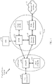
- FIGURE 1 is a diagram illustrating an LTE network architecture 100.
- the LTE network architecture 100 may be referred to as an Evolved Packet System (EPS) 100.
- the EPS 100 may include one or more user equipment (UE) 102, an evolved UMTS terrestrial radio access network (E-UTRAN) 104, an evolved packet core (EPC) 110, a home subscriber server (HSS) 120, and an operator's IP services 122.
- the EPS can interconnect with other access networks, but for simplicity those entities/interfaces are not shown.
- the EPS provides packet-switched services, however, as those skilled in the art will readily appreciate, the various concepts presented throughout this disclosure may be extended to networks providing circuit-switched services.
- the E-UTRAN includes the evolved Node B (eNodeB) 106 and other eNodeBs 108.
- the eNodeB 106 provides user and control plane protocol terminations toward the UE 102.
- the eNodeB 106 may be connected to the other eNodeBs 108 via a backhaul (e.g., an X2 interface).
- the eNodeB 106 may also be referred to as a base station, a base transceiver station, a radio base station, a radio transceiver, a transceiver function, a basic service set (BSS), an extended service set (ESS), or some other suitable terminology.
- the eNodeB 106 provides an access point to the EPC 110 for a UE 102.
- Examples of UEs 102 include a cellular phone, a smart phone, a session initiation protocol (SIP) phone, a laptop, a personal digital assistant (PDA), a satellite radio, a global positioning system, a multimedia device, a video device, a digital audio player (e.g., MP3 player), a camera, a game console, or any other similar functioning device.
- SIP session initiation protocol
- PDA personal digital assistant
- the UE 102 may also be referred to by those skilled in the art as a mobile station, a subscriber station, a mobile unit, a subscriber unit, a wireless unit, a remote unit, a mobile device, a wireless device, a wireless communications device, a remote device, a mobile subscriber station, an access terminal, a mobile terminal, a wireless terminal, a remote terminal, a handset, a user agent, a mobile client, a client, or some other suitable terminology.
- the eNodeB 106 is connected to the EPC 110 via, e.g., an S1 interface.
- the EPC 110 includes a mobility management entity (MME) 112, other MMEs 114, a serving gateway 116, and a packet data network (PDN) Gateway 118.
- MME mobility management entity
- PDN packet data network
- the MME 112 is the control node that processes the signaling between the UE 102 and the EPC 110.
- the MME 112 provides bearer and connection management. All user IP packets are transferred through the serving gateway 116, which itself is connected to the PDN Gateway 118.
- the PDN Gateway 118 provides UE IP address allocation as well as other functions.
- the PDN Gateway 118 is connected to the Operator's IP Services 122.
- the operator's IP services 122 may include the Internet, the Intranet, an IP multimedia subsystem (IMS), and a PS streaming service (PSS).
- IMS IP multimedia subsystem
- PSS PS streaming service
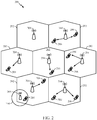
- FIGURE 2 is a diagram illustrating an example of an access network 200 in an LTE network architecture.
- the access network 200 is divided into a number of cellular regions (cells) 202.
- One or more lower power class eNodeBs 208 may have cellular regions 210 that overlap with one or more of the cells 202.
- a lower power class eNodeB 208 may be a remote radio head (RRH), a femto cell (e.g., home eNodeB (HeNB)), a pico cell, or a micro cell.
- the macro eNodeBs 204 are each assigned to a respective cell 202 and are configured to provide an access point to the EPC 110 for all the UEs 206 in the cells 202.
- the eNodeBs 204 are responsible for all radio related functions including radio bearer control, admission control, mobility control, scheduling, security, and connectivity to the serving gateway 116.
- the modulation and multiple access scheme employed by the access network 200 may vary depending on the particular telecommunications standard being deployed.
- OFDM is used on the downlink
- SC-FDMA is used on the uplink to support both frequency division duplexing (FDD) and time division duplexing (TDD).
- FDD frequency division duplexing
- TDD time division duplexing
- FDD frequency division duplexing
- TDD time division duplexing
- EV-DO evolution-data optimized
- UMB ultra mobile broadband
- EV-DO and UMB are air interface standards promulgated by the 3rd Generation Partnership Project 2 (3GPP2) as part of the CDMA2000 family of standards and employs CDMA to provide broadband Internet access to mobile stations.
- 3GPP2 3rd Generation Partnership Project 2
- W-CDMA wideband-CDMA
- GSM global system for mobile communications
- E-UTRA evolved UTRA
- UMB ultra mobile broadband
- Wi-Fi IEEE 802.11
- WiMAX IEEE 802.16
- IEEE 802.20 flash-OFDM employing OFDMA.
- UTRA, E-UTRA, UMTS, LTE and GSM are described in documents from the 3GPP organization.
- CDMA2000 and UMB are described in documents from the 3GPP2 organization.
- the actual wireless communication standard and the multiple access technology employed will depend on the specific application and the overall design constraints imposed on the system.
- the eNodeBs 204 may have multiple antennas supporting MIMO technology.
- MIMO technology enables the eNodeBs 204 to exploit the spatial domain to support spatial multiplexing, beamforming, and transmit diversity.
- Spatial multiplexing may be used to transmit different streams of data simultaneously on the same frequency.
- the data streams may be transmitted to a single UE 206 to increase the data rate or to multiple UEs 206 to increase the overall system capacity. This is achieved by spatially precoding each data stream (i.e., applying a scaling of an amplitude and a phase) and then transmitting each spatially precoded stream through multiple transmit antennas on the downlink.
- the spatially precoded data streams arrive at the UE(s) 206 with different spatial signatures, which enables each of the UE(s) 206 to recover the one or more data streams destined for that UE 206.
- each UE 206 transmits a spatially precoded data stream, which enables the eNodeB 204 to identify the source of each spatially precoded data stream.
- Beamforming may be used to focus the transmission energy in one or more directions. This may be achieved by spatially precoding the data for transmission through multiple antennas. To achieve good coverage at the edges of the cell, a single stream beamforming transmission may be used in combination with transmit diversity.
- OFDM is a spread-spectrum technique that modulates data over a number of subcarriers within an OFDM symbol.
- the subcarriers are spaced apart at precise frequencies. The spacing provides "orthogonality" that enables a receiver to recover the data from the subcarriers.
- a guard interval e.g., cyclic prefix
- the uplink may use SC-FDMA in the form of a DFT-spread OFDM signal to compensate for high peak-to-average power ratio (PAPR).
- PAPR peak-to-average power ratio
- FIGURE 3 is a diagram 300 illustrating an example of a downlink frame structure in LTE.
- a frame (10 ms) may be divided into 10 equally sized subframes. Each subframe may include two consecutive time slots.
- a resource grid may be used to represent two time slots, each time slot including a resource block.
- the resource grid is divided into multiple resource elements.
- a resource block contains 12 consecutive subcarriers in the frequency domain and, for a normal cyclic prefix in each OFDM symbol, 7 consecutive OFDM symbols in the time domain, for a total of 84 resource elements.
- For an extended cyclic prefix a resource block contains 6 consecutive OFDM symbols in the time domain, resulting in 72 resource elements.
- the DL-RS include Cell-specific RS (CRS) (also sometimes called common RS) 302 and UE-specific RS (UE-RS) 304.
- UE-RS 304 are transmitted only on the resource blocks upon which the corresponding physical downlink shared channel (PDSCH) is mapped.
- PDSCH physical downlink shared channel
- the number of bits carried by each resource element depends on the modulation scheme. Thus, the more resource blocks that a UE receives and the higher the modulation scheme, the higher the data rate for the UE.
- FIGURE 4 is a diagram 400 illustrating an example of an uplink frame structure in LTE.
- the available resource blocks for the uplink may be partitioned into a data section and a control section.
- the control section may be formed at the two edges of the system bandwidth and may have a configurable size.
- the resource blocks in the control section may be assigned to UEs for transmission of control information.
- the data section may include all resource blocks not included in the control section.
- the uplink frame structure results in the data section including contiguous subcarriers, which may allow a single UE to be assigned all of the contiguous subcarriers in the data section.
- a UE may be assigned resource blocks 410a, 410b in the control section to transmit control information to an eNodeB.
- the UE may also be assigned resource blocks 420a, 420b in the data section to transmit data to the eNodeB.
- the UE may transmit control information in a physical uplink control channel (PUCCH) on the assigned resource blocks in the control section.
- the UE may transmit only data or both data and control information in a physical uplink shared channel (PUSCH) on the assigned resource blocks in the data section.
- An uplink transmission may span both slots of a subframe and may hop across frequency.
- a set of resource blocks may be used to perform initial system access and achieve uplink synchronization in a physical random access channel (PRACH) 430.
- the PRACH 430 carries a random sequence. Each random access preamble occupies a bandwidth corresponding to six consecutive resource blocks. The starting frequency is specified by the network. That is, the transmission of the random access preamble is restricted to certain time and frequency resources. There is no frequency hopping for the PRACH.
- the PRACH attempt is carried in a single subframe (1 ms) or in a sequence of few contiguous subframes and a UE can make only a single PRACH attempt per frame (10 ms).
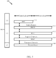
- FIGURE 5 is a diagram 500 illustrating an example of a radio protocol architecture for the user and control planes in LTE.
- the radio protocol architecture for the UE and the eNodeB is shown with three layers: Layer 1, Layer 2, and Layer 3.
- Layer 1 (L1 layer) is the lowest layer and implements various physical layer signal processing functions.
- the L1 layer will be referred to herein as the physical layer 506.
- Layer 2 (L2 layer) 508 is above the physical layer 506 and is responsible for the link between the UE and eNodeB over the physical layer 506.
- the L2 layer 508 includes a media access control (MAC) sublayer 510, a radio link control (RLC) sublayer 512, and a packet data convergence protocol (PDCP) 514 sublayer, which are terminated at the eNodeB on the network side.
- MAC media access control
- RLC radio link control
- PDCP packet data convergence protocol
- the UE may have several upper layers above the L2 layer 508 including a network layer (e.g., IP layer) that is terminated at the PDN gateway 118 on the network side, and an application layer that is terminated at the other end of the connection (e.g., far end UE, server, etc.).
- IP layer e.g., IP layer
- the PDCP sublayer 514 provides multiplexing between different radio bearers and logical channels.
- the PDCP sublayer 514 also provides header compression for upper layer data packets to reduce radio transmission overhead, security by ciphering the data packets, and handover support for UEs between eNodeBs.
- the radio link control (RLC) sublayer 512 provides segmentation and reassembly of upper layer data packets, retransmission of lost data packets, and reordering of data packets to compensate for out-of-order reception due to hybrid automatic repeat request (HARQ).
- HARQ hybrid automatic repeat request
- the MAC sublayer 510 provides multiplexing between logical and transport channels.
- the MAC sublayer 510 is also responsible for allocating the various radio resources (e.g., resource blocks) in one cell among the UEs.
- the MAC sublayer 510 is also responsible for HARQ operations.
- the radio protocol architecture for the UE and eNodeB is substantially the same for the physical layer 506 and the L2 layer 508 with the exception that there is no header compression function for the control plane.
- the control plane also includes a radio resource control (RRC) sublayer 516 in Layer 3 (L3 layer).
- the radio resource control (RRC) sublayer 516 is responsible for obtaining radio resources (i.e., radio bearers) and for configuring the lower layers using radio resource control signaling between the eNodeB and the UE.
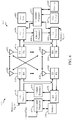
- FIGURE 6 is a block diagram of an eNodeB 610 in communication with a UE 650 in an access network.
- a controller/processor 675 implements the functionality of the L2 layer.
- the controller/processor 675 provides header compression, ciphering, packet segmentation and reordering, multiplexing between logical and transport channels, and radio resource allocations to the UE 650 based on various priority metrics.
- the controller/processor 675 is also responsible for HARQ operations, retransmission of lost packets, and signaling to the UE 650.
- the transmit processor 616 implements various signal processing functions for the L1 layer (i.e., physical layer).
- the signal processing functions includes coding and interleaving to facilitate forward error correction (FEC) at the UE 650 and mapping to signal constellations based on various modulation schemes (e.g., binary phase-shift keying (BPSK), quadrature phase-shift keying (QPSK), M-phase-shift keying (M-PSK), M-quadrature amplitude modulation (M-QAM)).
- FEC forward error correction
- BPSK binary phase-shift keying
- QPSK quadrature phase-shift keying
- M-PSK M-phase-shift keying
- M-QAM M-quadrature amplitude modulation
- Each stream is then mapped to an OFDM subcarrier, multiplexed with a reference signal (e.g., pilot) in the time and/or frequency domain, and then combined together using an inverse fast Fourier transform (IFFT) to produce a physical channel carrying a time domain OFDM symbol stream.
- the OFDM stream is spatially precoded to produce multiple spatial streams.
- Channel estimates from a channel estimator 674 may be used to determine the coding and modulation scheme, as well as for spatial processing.
- the channel estimate may be derived from a reference signal and/or channel condition feedback transmitted by the UE 650.
- Each spatial stream is then provided to a different antenna 620 via a separate transmitter 618TX.
- Each transmitter 618TX modulates an RF carrier with a respective spatial stream for transmission.
- each receiver 654RX receives a signal through its respective antenna 652. Each receiver 654RX recovers information modulated onto an RF carrier and provides the information to the receiver processor 656.
- the receiver processor 656 implements various signal processing functions of the L1 layer.
- the receiver processor 656 performs spatial processing on the information to recover any spatial streams destined for the UE 650. If multiple spatial streams are destined for the UE 650, they may be combined by the receiver processor 656 into a single OFDM symbol stream.
- the receiver processor 656 then converts the OFDM symbol stream from the time-domain to the frequency domain using a fast Fourier transform (FFT).
- FFT fast Fourier transform
- the symbols on each subcarrier, and the reference signal, is recovered and demodulated by determining the most likely signal constellation points transmitted by the eNodeB 610. These soft decisions may be based on channel estimates computed by the channel estimator 658. The soft decisions are then decoded and deinterleaved to recover the data and control signals that were originally transmitted by the eNodeB 610 on the physical channel. The data and control signals are then provided to the controller/processor 659.
- the controller/processor 659 implements the L2 layer.
- the controller/processor can be associated with a memory 660 that stores program codes and data.
- the memory 660 may be referred to as a computer-readable medium.
- the controller/processor 659 provides demultiplexing between transport and logical channels, packet reassembly, deciphering, header decompression, control signal processing to recover upper layer packets from the core network.
- the upper layer packets are then provided to a data sink 662, which represents all the protocol layers above the L2 layer.
- Various control signals may also be provided to the data sink 662 for L3 processing.
- the controller/processor 659 is also responsible for error detection using an acknowledgement (ACK) and/or negative acknowledgement (NACK) protocol to support HARQ operations.
- ACK acknowledgement
- NACK negative acknowledgement
- a data source 667 is used to provide upper layer packets to the controller/processor 659.
- the data source 667 represents all protocol layers above the L2 layer.
- the controller/processor 659 implements the L2 layer for the user plane and the control plane by providing header compression, ciphering, packet segmentation and reordering, and multiplexing between logical and transport channels based on radio resource allocations by the eNodeB 610.
- the controller/processor 659 is also responsible for HARQ operations, retransmission of lost packets, and signaling to the eNodeB 610.
- Channel estimates derived by a channel estimator 658 from a reference signal or feedback transmitted by the eNodeB 610 may be used by the TX processor 668 to select the appropriate coding and modulation schemes, and to facilitate spatial processing.
- the spatial streams generated by the TX processor 668 are provided to different antenna 652 via separate transmitters 654TX. Each transmitter 654TX modulates an RF carrier with a respective spatial stream for transmission.
- the uplink transmission is processed at the eNodeB 610 in a manner similar to that described in connection with the receiver function at the UE 650.
- Each receiver 618RX receives a signal through its respective antenna 620.
- Each receiver 618RX recovers information modulated onto an RF carrier and provides the information to a RX processor 670.
- the RX processor 670 may implement the L1 layer.
- the controller/processor 675 implements the L2 layer.
- the controller/processor 675 can be associated with a memory 676 that stores program codes and data.
- the memory 676 may be referred to as a computer-readable medium.
- the controller/processor 675 provides demultiplexing between transport and logical channels, packet reassembly, deciphering, header decompression, control signal processing to recover upper layer packets from the UE 650.
- Upper layer packets from the controller/processor 675 may be provided to the core network.
- the controller/processor 675 is also responsible for error detection using an ACK and/or NACK protocol to support HARQ operations.
- the spectrum available for Internet communication to aircraft by terrestrial air to ground (ATG) systems is limited for practical and economic reasons.
- Providing seamless communication with aircraft flying at high altitudes over a large area involves spectrum that is available over the large area. That is, the spectrum assigned to the ATG system should be available nationwide. It has been problematic, however, to identify a portion of spectrum that is available nationwide, much less arranging to free up such a portion of spectrum that is allocated for other uses.
- a large amount of spectrum is assigned to geostationary satellites for use in broadcast TV and two way fixed satellite service (FSS).
- FSS two way fixed satellite service
- a high data rate aircraft to ground communications antenna system provides an aircraft with Internet service.
- aspects of the present disclosure provide methods and apparatus for a next generation air to ground (Next-Gen AG) system.
- the Next-Gen AG system may include ground base stations (GBSs) in communication with aircraft transceivers (ATs) in airplanes that may use an uplink portion of spectrum assigned for satellite systems.
- GBSs ground base stations
- ATs aircraft transceivers
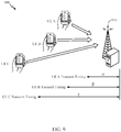
- FIGURE 7 A system 700 for Next-Gen AG communication according to an illustrative aspect of the present disclosure is shown in FIGURE 7 .
- the Next-Gen AG system 700 includes a ground base station 710 that transmits and receives signals on a satellite uplink band using a forward link (FL) 708-1 and a reverse link (RL) 706-1.
- a first aircraft 750-1 includes an aircraft antenna 800 and aircraft transceiver (AT) 650 ( FIGURE 6 ) in communication with the ground base station 710.
- the aircraft transceiver (AT) 650 may also receive and transmit signals on the satellite uplink band using the forward link 708-1 and the return link 706-1.
- the aircraft antenna 800 may include a directional antenna, for example, as shown in FIGURE 8 .
- FIGURE 8 shows one example of an aircraft antenna 800 having aircraft antenna arrays 802 (802-1,..., 802-N) operating at, for example, 14 gigahertz (GHz).
- the aircraft antenna array 802-1 has twelve horn antennas 804 (804-1,...,804-12) each covering 30° sectors in azimuth with an aperture size of approximately 2.0 inches x 0.45 inches, and having a gain of >10 dBi (dB isotropic). In one configuration, an overall diameter of the antenna array is roughly 8 inches.
- any directional antenna may be provided according to the aspects of the present disclosure. While the described aspect of the present disclosure are provided with reference to aircraft, the present disclosure is not limited thereto. Aspect of the present disclosure may apply to any current or future airborne objects that communicate with a ground station.
- the aircraft antenna 800 includes a multi-beam switchable array that is able to communicate with the ground base station 710 at any azimuth angle. As shown in FIGURE 7 , the aircraft antenna 800 is mounted below the fuselage with a small protrusion and aerodynamic profile to reduce or minimize wind drag. In one configuration, the antenna elevation coverage is from approximately 3° to 20° below horizon to provide, for example, the pointing directions for the antenna gain.
- the aircraft antenna 800 may include an array N of elements positioned such that each element directs a separate beam at different azimuth angles, each covering 360/N degrees, for example, as shown in FIGURE 8 .
- FIGURE 8 illustrates the aircraft antenna arrays 802 in a twelve-beam array configuration
- one example configuration includes four-antenna arrays in a four-beam array configuration.
- a directional antenna may be provided as part of the Next-Gen AG system 700 while remaining within the scope of the present disclosure.
- a second aircraft 750-2 includes a system having an aircraft antenna 800 that communicates with an aircraft transceiver (AT) 650, as shown in FIGURE 6 .
- the aircraft antenna 800 is in communication with the ground base station 710 and also receives and transmits signals on the satellite uplink band using a forward link 708-2 and a return link 706-2.
- a Next-Gen AG system may provide broadband connectivity to flying aircraft using an aircraft transceiver (AT) 650, as shown in FIGURE 6 .
- the aircraft transceiver may operate according to a time division long term evolution (TD-LTE) air interface.
- TD-LTE time division long term evolution
- a timing-advanced uplink transmission should not overlap with reception of any preceding downlink.
- a TD-LTE air interface may operate according to an orthogonal uplink intra-cell multiple access scheme.
- transmissions from different UEs (e.g., AT 650) in a cell are time aligned at the receiver of the eNodeB (e.g., the ground base station 710) to maintain uplink multiple access orthogonality.
- a timing advance may be applied at the UE transmitter to provide time alignment of the uplink transmissions relative to the received downlink timing.
- Using a timing advance at the base station may counteract the various propagation delays between different UEs.
- FIGURE 9 is a block diagram 900 in which a UE A, a UE B and a UE C are positioned at different distances from a base station 910.
- the differing distances from the base station 910 result in varying propagation delays from the different UEs to the base station 910.
- the UE transmissions are orthogonal when they arrive at the base station and are made synchronous in the time domain by performing timing advance (TA) signaling at the base station.
- TA timing advance
- the application of the timing advance at the base station synchronizes the UE transmissions within a fraction of the CP (cyclic prefix) length.
- a timing advance command may be sent as a medium access control (MAC) element with a 0.52 microsecond timing resolution and from 0 up to a maximum of 0.67 milliseconds in a baseline TD-LTE configuration.
- MAC medium access control
- the UE A receives a timing advance ( ⁇ )
- UE B receives a timing advance ( ⁇ )
- UE C receives a timing advance ( ⁇ ) to enable time alignment at the receiver of the base station 910.
- TD-LTE Time division duplex
- UE downlink to uplink
- eNodeB base station
- TDD time division duplex
- a TD-LTE air interface may prevent overlap between downlink and uplink communication by specifying a transmission gap (e.g., a guard period (GP)) between the downlink and uplink communications.
- a transmission gap e.g., a guard period (GP)
- the guard period between reception (downlink) and transmission (uplink) may be specified to accommodate a greatest possible timing advance and any switching delay.
- the timing advance of the TD-LTE air interface is a function of the round-trip propagation delay.
- the total guard time for an uplink-downlink cycle of a TD-LTE air interface may be longer than the worst round-trip propagation delay supported by a cell.
- FIGURE 10 is a timing diagram 1000 in which a guard period (T GP ) 1012 between a downlink communication 1008-1 and an uplink communication 1006-1 of an eNodeB is selected to prevent overlap between a downlink communication 1008-2 and an uplink communication 1006-2 of a UE 1050.
- the guard period (T GP ) should exceed both a round-trip propagation delay (2T P ) and a receive-to-transmit switching delay (T UE-Rx-Tx ) 1016 at the UE 1050, where T P denotes the one-way propagation delay.
- the guard period (T GP ) may be computed according the following equation: T GP > 2 T P + T UE-Rx-tx
- the 3GPP LTE specification is limited to a guard period duration of approximately 0.72 milliseconds. This guard period duration presumes a maximum one-hundred (100) kilometer cell radius. In a Next-Gen AG system, however, a larger cell size (e.g., a cell radius of two-hundred fifty (250) to three hundred fifty (350) kilometers) may be specified.
- FIGURE 11 is a timing diagram 1100 in which a duration of the guard period (T GP ) 1112 between a downlink communication 1008-1 and an uplink communication 1006-1 of an eNodeB 1010 is insufficient, resulting in an overlap 1120 between a downlink communication 1008-2 and an uplink communication 1006-2 of the UE 1050.
- T GP guard period
- the frame structure used by an air interface of a Next-Gen AG system structure is modified.
- a TD-LTE frame structure with a two (2) millisecond special subframe is specified to support a cell radius on the order of two-hundred (200) to two-hundred fifty (250) kilometers.
- a TD-LTE frame structure with a three (3) millisecond special subframe is specified to support a cell radius on the order of three-hundred (300) to three-hundred fifty (350) kilometers.
- a nested frame structure provides co-existence between different uplink-downlink subframe configurations.
- air cells are categorized into multiple zones based on the distance to a base station (e.g., an eNodeB 610).
- a base station e.g., an eNodeB 610
- different uplink/downlink subframe configurations corresponding to different round-trip propagation delays are used to accommodate communication with each of the multiple zones.
- the nested frame structure enables dynamic variation as an airborne object moves from one zone to another.
- the nested frame structure enables dynamic switching between various special subframes lengths in each zone. This dynamic switching may be achieved with or without a break in the call.
- the nested frame structure becomes a dynamic frame structure.
- the nested frame structure dynamically varies between a non-extended special subframe, a first extended special subframe and a second extended special subframe as the UE moves between difference zones of an air cell (e.g., Zone 0, Zone 1 and Zone 2 of FIGURE 23 ).
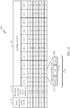
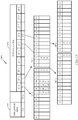
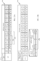
- FIGURE 12 is a block diagram illustrating a conventional TD-LTE radio frame structure 1200.
- the conventional TD-LTE radio frame structure 1200 includes a subframe number 1230, an uplink-downlink configuration column 1232 and a downlink-to-uplink switch-point periodicity column 1234.
- the TD-LTE radio frame structure spans ten (10) milliseconds and consists of ten (10) one (1) millisecond subframes (SF 0, ..., SF 9).
- the various subframes may be configured as a downlink (D) subframe, an uplink (U) subframe or a special (S) subframe.
- SF 1 is configured as a special subframe in each of the seven (0, ..., 6) uplink-downlink configurations; SF 6 is configured as a special subframe in uplink-downlink configurations 0, 1, 2 and 6.
- the special subframe 1240 serves as a switching point between downlink and uplink communications.
- the special subframe 1240 includes a downlink pilot time slot (DwPTS) portion 1242, a guard period (GP) portion 1244 and an uplink pilot time slot (UpPTS) portion 1246.
- DwPTS downlink pilot time slot
- GP guard period
- UpPTS uplink pilot time slot
- the DwPTS portion 1242 of the special subframe 1240 may be treated as a regular but shortened downlink subframe.
- the DwPTS portion 1242 usually contains a reference signal (RS), control information and a primary synchronization signal (PSS).
- RS reference signal
- PSS primary synchronization signal
- the DwPTS portion may also carry data transmissions.
- the UpPTS portion 1246 of the special subframe 1240 may be used for either a sounding reference signal (e.g., a one (1) symbol length) or a special (random access channel (RACH) for a small cell size (e.g., a two (2) symbol length).
- a sounding reference signal e.g., a one (1) symbol length
- RACH random access channel
- the GP portion 1244 of the special subframe 1240 provides a switching point between downlink and uplink communications.
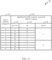
- FIGURE 13 is a table 1300 illustrating special subframe component lengths according to the various special subframe configurations based on a normal cyclic prefix (CP).
- the table 1300 includes a special subframe configuration column 1332, a DwPTS column 1342, a GP column 1344 and a UpPTS column 1346 within a component length column 1336.
- the component lengths are indicated in units of orthogonal frequency division multiplexing (OFDM) symbols.
- OFDM orthogonal frequency division multiplexing
- FIGURE 14 illustrates the time-domain resource allocation of synchronization and broadcast channels within the subframes of a TD-LTE radio frame structure 1400 based on a configuration index 1432 and a subframe number 1430.
- a primary synchronization signal PSS
- PSS primary synchronization signal
- a secondary synchronization signal SSS
- SSS secondary synchronization signal
- a physical broadcast channel (PBCH) is allocated within OFDM symbols 7-10 of subframe 0 (e.g., every ten (10) milliseconds).
- a system information block of type 1 (SIB1) is allocated within subframe 5 (e.g., an even radio frame).
- the radio frame structure used by an air interface of a Next-Gen AG system structure is modified to accommodate a larger cell radius.
- a TD-LTE air interface may prevent overlap between uplink and downlink communication by specifying a transmission gap (e.g., a guard period (GP)) between the downlink and uplink communications.
- GP guard period
- the 3GPP LTE specification is limited to guard period durations on the order of 0.714 milliseconds (see equation (2)). This guard period duration presumes a maximum one-hundred (100) kilometer cell radius.
- a larger cell size e.g., a cell radius of two-hundred fifty (250) to three hundred fifty (350) kilometers is specified.
- a special subframe is redesigned to enable downlink to uplink switching with a large round trip delay (RTD).
- RTD round trip delay
- T GP a guard period that exceeds a round-trip propagation delay (2T P ) and a receive-to-transmit switching delay (T UE-Rx-Tx ) 1016 at the UE 1050, where T P denotes the one-way propagation delay.
- the guard period (T GP ) may be computed according to equation (1).
- the 3GPP LTE specification is limited to a smaller guard period duration (e.g., 0.714 milliseconds) to support a maximum one-hundred (100) kilometer cell radius.
- the guard period is computed as follows: T GP > 1.67 milliseconds + T UE-Rx-Tx
- FIGURE 15 is a block diagram illustrating a modified radio frame structure 1500 according to one aspect of the present disclosure.
- This configuration of the modified radio frame structure 1500 maintains the 3GPP synchronization/broadcast channel structure shown in FIGURE 14 .
- subframes 0, 1, 5 and 6 are either downlink or special subframes to allow primary synchronization signal (PSS), secondary synchronization signal (SSS), broadcast control channel (BCCH), dynamic broadcast channel (D-BCH) and system information block of type 1 (SIB1) transmissions.
- PSS primary synchronization signal
- SSS secondary synchronization signal
- BCCH broadcast control channel
- D-BCH dynamic broadcast channel
- SIB1 system information block of type 1
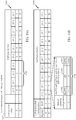
- FIGURE 16A is a block diagram illustrating one configuration of a TD-LTE radio frame structure with a first extended special subframe (e.g., two (2) milliseconds) to support a first extended cell radius on the order of two-hundred fifty (250) kilometers.
- the frame structure 1600 has a ten (10) millisecond periodicity that includes an extended special subframe 1650 that extends over subframe 1 and subframe 2.
- This frame structure 1600 supports Next-Gen AG system configurations A and B, as noted by the configuration index 1632.
- the Next-Gen AG system configuration A is based on uplink-downlink configuration zero (0), as shown in FIGURE 12 .
- the Next-Gen AG system configuration B is based on uplink-downlink configuration three (3), as shown in FIGURE 12 .
- FIGURE 16B further illustrates a modified special subframe 1640 to enable formation of the extended special subframe 1650 shown in FIGURE 16A .
- the modified special subframe 1640 includes a downlink pilot time slot (DwPTS) portion 1642 and a guard period (GP) portion 1644.
- DwPTS downlink pilot time slot
- GP guard period
- An uplink pilot time slot (UpPTS) portion 1646 and the adjacent uplink subframe (e.g., SF 2 and/or SF 7) are omitted (muted) to extend the guard period (GP) portion 1644 to form the extended special subframe 1650 ( FIGURE 16A ).
- the guard period (GP) portion 1644 may be combined with a GP portion of a muted, adjacent uplink subframe (e.g., SF 2, SF 7 and SF 12) to provide a twenty five (25) OFDM symbol length (e.g. 1.785 ms), depending on whether a normal or extended cyclic prefix is used.
- the DwPTS portion 1642 of the modified special subframe 1640 is treated as a regular, but shortened downlink subframe.
- the DwPTS portion 1642 may have a three (3) OFDM symbol length, used to transmit a reference signal (RS), control information, a primary synchronization signal (PSS), and the like.
- special subframe configuration zero (0) is applied while muting the UpPTS portion 1646.
- the UpPTS portion 1646 may be muted by not scheduling any sounding reference signals.
- uplink subframe 2 adjacent to special subframe 1 is muted to provide the extended special subframe 1650 as a two (2) millisecond extended special subframe.
- the uplink subframe 2 is muted by not scheduling any uplink data transmissions during uplink subframe 2. Muting the uplink subframe 2 may also involve moving any acknowledgement (ACK)/negative acknowledgement (NACK) feedback to a next suitable subframe. Also, any channel quality information (CQI), precoding matrix indicator, and/or rank indicator information is not reported during the uplink subframe 2.
- CQI channel quality information
- precoding matrix indicator precoding matrix indicator
- rank indicator information is not reported during the uplink subframe 2.
- SRS sounding reference signal
- SR scheduling request
- PRACH physical random access channel
- FIGURE 17A illustrates another configuration of a TD-LTE frame structure 1700 with a first extended special subframe (e.g., two (2) milliseconds) also specified to support the first extended cell radius (e.g., two-hundred (200) to two-hundred fifty (250) kilometers).
- the TD-LTE frame structure 1700 has a twenty (20) millisecond periodicity with an extended special subframe 1750 that extends over special subframe 1 and uplink subframe 2.
- the extended special subframe 1750 includes a downlink pilot time slot (DwPTS) portion 1752 and an extended guard period (GP) portion 1754.
- DwPTS downlink pilot time slot
- GP extended guard period
- the Next-Gen AG system configuration C dynamically switches between uplink-downlink configuration zero (0), and uplink-downlink configuration three (3), as shown in FIGURE 12 .
- uplink-downlink configuration zero (0) may be used for example, even subframes may use uplink-downlink configuration zero (0) and odd subframes may use uplink-downlink configuration three (3).
- FIGURE 17B further illustrates a modified special subframe 1740 to enable formation of the extended special subframe 1750, shown in FIGURE 17A .
- the modified special subframe 1740 includes a downlink pilot time slot (DwPTS) portion 1742 and a guard period (GP) portion 1744.
- An uplink pilot time slot (UpPTS) portion 1746 and an adjacent uplink subframe (e.g., SF 2, SF 7 and/or SF 12) are omitted (e.g., muted) to extend the guard period (GP) portion 1744 to form the extended special subframe 1750 ( FIGURE 17A ).
- the DwPTS portion 1742 of the modified special subframe 1740 is treated as a regular, but shortened downlink subframe.
- the DwPTS portion 1742 may have a three (3) OFDM symbol length to transmit a reference signal (RS), control information, a primary synchronization signal (PSS), and the like.
- the guard period (GP) portion 1744 may be combined with a GP portion of a muted, adjacent uplink subframe (e.g., SF 2, SF 7 and SF 12) to provide a twenty five (25) OFDM symbol length (e.g. 1.785 ms).
- a maximum timing advance of approximately 1.67 milliseconds is applied at the base station (e.g., an eNodeB 610) to synchronize communication.
- the UpPTS portion 1746 may be muted by not scheduling any sounding reference signals.
- the uplink subframe 2, adjacent to special subframe 1 is muted to provide the extended special subframe 1750 as a two (2) millisecond extended special subframe.
- the uplink subframe 2 may be muted by not scheduling any uplink data transmissions during uplink subframe 2. Muting the uplink subframe 2 may also involve moving any acknowledgement (ACK)/negative acknowledgement (NACK) feedback to a next suitable subframe. Also, any channel quality information (CQI), precoding matrix indicator, and/or rank indicator information is not reported during uplink subframe 2.
- no sounding reference signal (SRS), scheduling request (SR), and/or physical random access channel (PRACH) transmission are performed during uplink subframe 2.
- SRS sounding reference signal
- SR scheduling request
- PRACH physical random access channel
- FIGURE 18A illustrates another configuration of a TD-LTE frame structure 1800 with a second extended special subframe (e.g., three (3) milliseconds) specified to support a second extended cell radius on the order of three-hundred (300) to three-hundred fifty (350) kilometers.
- the TD-LTE frame structure 1800 has a ten (10) millisecond periodicity with an extended special subframe 185 that extends over subframe 1, subframe 2 and subframe 3.
- the extended special subframe 1850 includes a downlink pilot time slot (DwPTS) portion 1852 and an extended guard period (GP) portion 1854.
- DwPTS downlink pilot time slot
- GP extended guard period
- the Next-Gen AG system configuration D is based on uplink-downlink configuration zero (0), as shown in FIGURE 12 .
- the Next-Gen AG system configuration E is based on uplink-downlink configuration three (3), as shown in FIGURE 12 .
- FIGURE 18B illustrates a modified special subframe 1840 to enable formation of the extended special subframe 1850, shown in FIGURE 18A .
- the modified special subframe 1840 also includes a downlink pilot time slot (DwPTS) portion 1842 and a guard period (GP) portion 1844.
- DwPTS downlink pilot time slot
- GP guard period
- An uplink pilot time slot (UpPTS) portion 1846 and the two contiguous, adjacent uplink subframes e.g., SF 2 and SF 3, SF 7 and SF 8) are omitted (e.g., muted) to extend the guard period (GP) portion 1844 to form the extended special subframe 1850 ( FIGURE 18A ).
- the guard period (GP) portion 1844 may be combined with a GP portion of a muted, adjacent uplink subframe (e.g., SF 2 and SF 3, SF 7 and SF 8) to provide a thirty nine (39) OFDM symbol length (e.g. 2.72 milliseconds).
- the DwPTS portion 1842 of the modified special subframe 1840 is also treated as a regular, but shortened downlink subframe.
- the DwPTS portion 1842 may have a three (3) OFDM symbol length to transmit a reference signal (RS), control information, a primary synchronization signal (PSS), and the like.
- RS reference signal
- PSS primary synchronization signal
- special subframe configuration zero (0) is also applied while muting the UpPTS portion 1846.
- the UpPTS portion 1846 is muted by not scheduling any sounding reference signals.
- uplink subframe 2 and uplink subframe 3 adjacent to special subframe 1 are muted to provide the extended special subframe 1850 as a three (3) millisecond extended special subframe.
- uplink subframe 2 and uplink subframe 3 are muted by not scheduling any uplink data transmissions during uplink subframes 2 and 3. Muting uplink subframes 2 and 3 may also involve moving any acknowledgement (ACK)/negative acknowledgement (NACK) feedback to a next suitable subframe.
- ACK acknowledgement
- NACK negative acknowledgement
- any channel quality information (CQI), precoding matrix indicator, and/or rank indicator information is not reported during uplink subframes 2 and 3.
- no sounding reference signal (SRS), scheduling request (SR), and/or physical random access channel (PRACH) transmission are performed during the uplink subframes 2 and 3.
- SRS sounding reference signal
- SR scheduling request
- PRACH physical random access channel
- FIGURE 19A illustrates another configuration of a TD-LTE frame structure 1900 with a three (3) millisecond special subframe specified to support the second extended cell radius (e.g., three-hundred fifty (350) to four-hundred (400) kilometers).
- the TD-LTE frame structure 1900 has a twenty (20) millisecond periodicity with an extended special subframe 1950 that extends over subframes 1 to 3, 6 to 8 and 11 to 13.
- the extended special subframe 1950 includes a downlink pilot time slot (DwPTS) portion 1952 and an extended guard period (GP) portion 1954.
- DwPTS downlink pilot time slot
- GP extended guard period
- the Next-Gen AG system configuration F dynamically switches between uplink-downlink configuration zero (0), and uplink-downlink configuration three (3), as shown in FIGURE 12 .
- uplink-downlink configuration zero (0) may be used for example, even subframes may use uplink-downlink configuration zero (0) and odd subframes may use uplink-downlink configuration three (3).
- FIGURE 19B illustrates a modified special subframe 1940 to enable formation of the extended special subframe 1950, shown in FIGURE 19A .
- the modified special subframe 1940 includes a downlink pilot time slot (DwPTS) portion 1942 and a guard period (GP) portion 1944.
- An uplink pilot time slot (UpPTS) portion 1946 and the two contiguous, adjacent uplink subframes (e.g., SF 2 and SF 3, SF 7 and SF 8, SF 12 and SF 13) are omitted (e.g., muted) to extend the guard period (GP) portion 1944 to form the extended special subframe 1950 ( FIGURE 19A ).
- the DwPTS portion 1942 of the modified special subframe 1940 is treated as a regular, but shortened downlink subframe.
- the DwPTS portion 1942 may have a three (3) OFDM symbol length, used to transmit a reference signal (RS), control information, a primary synchronization signal (PSS), and the like.
- the guard period (GP) portion 1944 may be combined with a GP portion of a muted, adjacent uplink subframe (e.g., SF 2 and SF 3, SF 7 and SF 8, SF 12 and SF 13) to provide a thirty nine (39) OFDM symbol length (e.g. 2.72 milliseconds).
- a maximum timing advance of approximately 2.66 milliseconds is applied at the base station (e.g., an eNodeB 610) to synchronize communication.
- special subframe configuration zero (0) is also applied while muting the UpPTS portion 1946.
- the UpPTS portion 1946 may be muted by not scheduling any sounding reference signals.
- uplink subframes 2 and 3 adjacent to special subframe 1 are muted to provide the extended special subframe 1950 as a three (3) millisecond extended special subframe.
- uplink subframes 7 and 8 as well as uplink subframes 12 and 13 are muted.
- Uplink subframe 2 and 3, 7 and 8, and 12 and 13 may be muted by not scheduling any uplink data transmissions during these uplink subframes. Muting these uplink subframes may also involve moving any acknowledgement (ACK)/negative acknowledgement (NACK) feedback to a next suitable subframe.
- ACK acknowledgement
- NACK negative acknowledgement
- any channel quality information (CQI), precoding matrix indicator, and/or rank indicator information is not reported during these uplink subframes.
- no sounding reference signal (SRS), scheduling request (SR), and/or physical random access channel (PRACH) transmission are performed during these uplink subframes.
- SRS sounding reference signal
- SR scheduling request
- PRACH physical random access channel
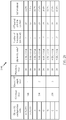
- FIGURE 20 is a table 2000 of the guard time overhead associated with the Next-Gen AG system configurations for supporting the first extended cell radius and the second extend cell radius as compared to a conventional (non-extended) cell radius.
- the 3GPP LTE specification is limited to a guard time duration of approximately 0.72 milliseconds (e.g., 10 OFDM symbols). This guard period duration presumes a maximum one-hundred (100) kilometer cell radius, referred to herein as a non-extended cell radius.
- extended cell radii e.g., a cell radius of two-hundred fifty (250) to three hundred fifty (350) kilometers
- a guard time for a first extended cell radius (e.g., two-hundred fifty (250) kilometers) is approximately 1.78 milliseconds (e.g., twenty five (25) OFDM symbols).
- a guard time for a second extended cell radius (e.g., three-hundred fifty (350) kilometers) is approximately 2.72 milliseconds (e.g., thirty nine (39) OFDM symbols).
- the table 2000 illustrates that supporting extended cell radii results in reduced system throughput as noted by the guard time (GT) overhead column.
- the system throughput loss due to the guard time overhead is in proportion to the coverage range (1:2.5:3.5).
- Supporting the extended cell radii involves a tradeoff between system throughput, uplink/downlink fairness (see DL-to-UL ratio column) and implementation complexity.
- the table 2000 illustrates that the Next-Gen AG system configurations B and F involve less guard time overhead, but with an unbalanced ratio of downlink/uplink flows.
- complexity varies between implementing an extended special subframe with a ten (10) millisecond periodicity and an extended special subframe with a twenty (20) millisecond periodicity. It should be noted that the DL-to-UL ratio column of the table 2000 does not include DwPTS in the special subframe.
- a nested frame structure provides co-existence between different uplink-downlink subframe configurations.
- air cells may be categorized into multiple zones based on the distance to a base station (e.g., an eNodeB 610).
- a base station e.g., an eNodeB 610
- different uplink/downlink subframe configurations corresponding to different round-trip propagation delays may be used to accommodate communication with each of the multiple zones.
- FIGURE 21 illustrates categorization of an air cell 2100 into multiple zones to support extended cell radii according to one aspect of the present disclosure.
- the air cell 2100 includes an non-extended zone (Zone 0) for aircraft transceivers (ATs) that are less than eighty (80) to one-hundred (100) kilometers from a base station (e.g., eNodeB).
- the air cell 2100 also includes a first extended zone (Zone 1) for aircraft transceivers (ATs) that are less than two-hundred (200) to two-hundred fifty (250) kilometers from a base station (e.g., eNodeB).
- the air cell 2100 further includes a second extended zone (Zone 2) for aircraft transceivers (ATs) that are greater than two-hundred (200) to two-hundred fifty (250) kilometers from a base station (e.g., eNodeB).
- a first aircraft transceiver AT 1 is in the first zone (Zone 1) and a second aircraft transceiver AT 2 is in the second zone (Zone 2).
- the Airborne Object could be within Zone 0, and thus does not apply extended special subframe at all.
- the nested frame structure could dynamically change from applying an extended special subframe to applying a non-extended special subframe in co-ordination with a base station.
- Categorizing the air cell 2100 into multiple zones to support extended cell radii involves a tradeoff between system capacity and cell coverage.
- Using a two (2) millisecond extended special subframe involves less guard time overhead (e.g., reasonable system throughput), but cell coverage is limited to 250 kilometers.
- Using a three (3) millisecond extended special subframe ( FIGURES 18A-19B ) provides larger cell coverage with less system throughput (e.g., more guard time overhead).
- one aspect of the present disclosure enables coexistence between the two (2) millisecond extended special subframe and the three (3) millisecond extended special subframe by providing a nested frame structure, for example, as shown in FIGURES 22A and 22B .
- the various zones of the present disclosure are not limited to these specific distances.
- the base station applies the two (2) millisecond extended special subframe when an aircraft transceiver (AT) is detected with a first extended cell radius.
- the eNodeB applies a first extended special subframe (e.g., Next-Gen AG system configuration C) for communication with AT 1, which is detected within Zone 1.
- the eNodeB applies a second extended special subframe (e.g., Next-Gen AG system configuration F) for communication with AT 2, which is detected within Zone 2.
- first extended special subframe e.g., Next-Gen AG system configuration C
- a second extended special subframe e.g., Next-Gen AG system configuration F
- most aircraft are within Zone 1 and operate with high system capacity by using the first extended special subframe.
- only a few cell-edge aircrafts are within Zone 2 in which a longer guard time is applied to prevent overlap between downlink and uplink transmissions.
- FIGURE 22A is a block diagram illustrating a nested frame structure 2200 according to one aspect of the present disclosure.
- This configuration of a nested frame structure 2200 enables support for both a first extended special subframe 2260 and a second extended special subframe 2262.
- the nested frame structure 2200 may switch between a first extended special subframe 2260 that extends over subframes SF 1 and SF 2 (SF 6 and SF 7, SF 11 and SF 12) and a second extended special subframe 2262 that extends over subframes SF 1 to SF 3 (SF 6 to SF 8 and SF 11 to SF 13).
- This nested frame structure 2200 supports switching between Next-Gen AG system configurations C and F, as noted by the configuration index 2232.
- the Next-Gen AG system configurations C and F dynamically switch between uplink-downlink configuration zero (0) and uplink-downlink configuration three (3), as shown in FIGURE 12 .
- even subframes may use uplink-downlink configuration zero (0) and odd subframes may use uplink-downlink configuration three (3).
- FIGURE 22B further illustrates an extended special subframe 2240 according to another aspect of the present disclosure.
- the extended special subframe 2240 includes a downlink pilot time slot (DwPTS) portion 2242 and a guard period (GP) portion 2244.
- An uplink pilot time slot (UpPTS) portion 2246 is omitted (e.g., muted) to extend the guard period (GP) portion 2244 of the extended special subframe 2240.
- the DwPTS portion 2242 of the extended special subframe 2240 is treated as a regular, but shortened downlink subframe.
- the special subframe configuration zero (0) is also applied while muting the UpPTS portion 2246.
- the UpPTS portion 2246 may be muted by not scheduling any sounding reference signals.
- uplink subframes SF 2, SF 7 and SF 12 are muted to provide the extended special subframe 2240.
- the extended special subframe is configured as the first extended special subframe 2250 having a two (2) millisecond duration, as shown in FIGURE 22A .
- uplink subframes SF 2 and SF 3, SF 7 and SF 8, as well as uplink subframes SF 12 and SF 13 are muted to provide the second extended special subframe 2252 having a three (3) millisecond duration, as shown in FIGURE 22A .
- the uplink subframes may be muted by not scheduling any uplink data transmissions during these uplink subframes. Muting these uplink subframes may also involve moving any acknowledgement (ACK)/negative acknowledgement (NACK) feedback to a next suitable subframe. Also, any channel quality information (CQI), precoding matrix indicator, and/or rank indicator information is not reported during these uplink subframes. In addition, no sounding reference signal (SRS), scheduling request (SR), and/or random access channel (RACH) transmission are performed during these uplink subframes.
- SRS sounding reference signal
- SR scheduling request
- RACH random access channel
- FIGURE 23 illustrates a further categorization of air cells 2300 (2300-1, 2300-2 and 2300-3) into multiple zones to support extended cell radii according to one aspect of the present disclosure.
- the air cells 2300 include a first zone (Zone 1) for aircraft transceivers (ATs) that are less than two-hundred fifty (250) kilometers from a base station (e.g., eNodeB).
- the air cells 2300 also include a second zone (Zone 2) for aircraft transceivers (ATs) that are greater than two-hundred fifty (250) kilometers from a base station (e.g., eNodeB).
- a first aircraft transceiver AT 1 is in a first zone (Zone 1) of a first air cell 2300-1, and a second aircraft transceiver AT 2 is in a second zone (Zone 2) at a cell-edge of a third air cell 2300-3.
- Using the nested frame structure 2200 by a base station involves categorization of aircraft within the various zones of the air cells 2300.
- the base station uses the instantaneous location of all serving aircraft to categorize the aircraft within the various zones of the air cells 2300.
- position location logic at each served aircraft transceiver communicates a zone index to the base station via a physical uplink shared channel (PUSCH), a physical uplink control channel (PUCCH), a physical uplink random access channel (PRACH) or other like uplink channels.
- position location logic of the base station computes a zone index of each served aircraft transceiver (AT).
- the position location logic may be a global position system (GPS), differential GPS, or other position detection scheme.
- the first air cell 2300-1 is supported by eNodeB A
- the second air cell 2300-2 is supported by eNodeB B
- the third air cell 2300-2 is supported by eNodeB C.
- a first aircraft transceiver AT 1 is less than two-hundred fifty (250) kilometers from the eNodeB A
- a second aircraft transceiver AT 2 is greater than two-hundred fifty (250) kilometers from eNodeB C at the cell-edge of the third air cell 2300-3. Due to the increased timing advance applied at the base station for supporting the extended special subframes, uplink transmissions from aircrafts (e.g., AT 1) in Zone 1 may generate interference to neighbor cell's downlink transmission to aircraft (e.g., AT 2) in Zone 2.
- uplink-to-downlink interference is mitigated by the directional antenna pattern at AT 1 and AT 2. That is, the interference over thermal noise (IoT) is quite small due to the roll-off in azimuth and elevation angle of the aircraft antenna relative to the boresight.
- the size of Zone 1 is reduced to avoid the uplink-to-downlink overlap.
- the base station adjusts the uplink scheduling depending on the aircraft location. In this example, uplink transmission of AT 1 in Zone 1 are scheduled in subframes SF 3, SF 4, SF 8, SF 9, SF 13 and SF 14, as shown in FIGURE 22 . When AT 2 is in Zone 2, subframes SF 3, SF 8 and SF 13 are muted.
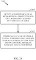
- FIGURE 24 illustrates a method 2400 for modification of a time division long term evolution (TD-LTE) frame structure according to an aspect of the present disclosure.
- a position of a UE is detected as being within a first extended cell radius or a second extended cell radius outside of a non-extended cell radius (e.g., less than one-hundred (100) kilometers).
- a first extended cell radius may be greater than one-hundred (100) kilometers and less than or equal to two-hundred fifty kilometers.
- a second extended cell radius may be greater than two-hundred fifty kilometers.
- an eNodeB communicates with the UE using a special subframe that extends over an uplink pilot time slot and one or more disabled, adjacent uplink subframes.
- the eNodeB may communicate using a first extended special subframe when the position of the UE is within the first extended cell radius.
- the eNodeB may also communicate using a second extended special subframe (see FIGURES 18A to 19B ) when the position of the UE is within the second extended cell radius.
- a length of the second extended special subframe is greater than a length of the first extended special subframe because the second extended cell radius is greater than the first extended cell radius.
- FIGURE 25 is a diagram illustrating an example of a hardware implementation for an apparatus 2500 employing a Next-Gen AG system 2514 according to one aspect of the present disclosure.
- the Next-Gen AG system 2514 may be implemented with a bus architecture, represented generally by a bus 2524.
- the bus 2524 may include any number of interconnecting buses and bridges depending on the specific application of the Next-Gen AG system 2514 and the overall design constraints.
- the bus 2524 links together various circuits including one or more processors and/or hardware modules, represented by a processor 2526, a detecting module 2502, a communicating module 2504, and a computer-readable medium 2528.
- the bus 2524 may also link various other circuits such as timing sources, peripherals, voltage regulators, and power management circuits, which are well known in the art, and therefore, will not be described any further.
- the apparatus includes a Next-Gen AG system 2514 coupled to a transceiver 2522.
- the transceiver 2522 is coupled to one or more antennas 2520.
- the transceiver 2522 provides a means for communicating with various other apparatus over a transmission medium.
- the Next-Gen AG system 2514 includes the processor 2526 coupled to the computer-readable medium 2528.
- the processor 2526 is responsible for general processing, including the execution of software stored on the computer-readable medium 2528.
- the software when executed by the processor 2526, causes the Next-Gen AG system 2514 to perform the various functions described supra for any particular apparatus.
- the computer-readable medium 2528 may also be used for storing data that is manipulated by the processor 2526 when executing software.
- the Next-Gen AG system 2514 further includes the detecting module 2502 for detecting a position of a UE as being within a first extended cell radius or a second extended cell radius.
- the Next-Gen AG system 2514 further includes the communicating module 2504 for communicating with the UE using a special subframe that extends over an uplink pilot time slot and one or more disabled, adjacent uplink subframes.
- the detecting module 2502 and the communicating module 2504 may be software modules running in the processor 2526, resident/stored in the computer-readable medium 2528, one or more hardware modules coupled to the processor 2526, or some combination thereof.
- the Next-Gen AG system 2514 may be a component of the eNodeB 610 and/or the UE 650.
- the apparatus 2500 for wireless communication includes means for detecting and means for communicating.
- the means may be the detecting module 2502, the communicating module 2504 and/or the Next-Gen AG system 2514 of the apparatus 2500 configured to perform the functions recited by the detecting means and the communicating means.
- the detecting means may be the controller/processor 675 and/or memory 676 configured to perform the functions recited by the detecting means.
- the communicating means may be the controller/processor 675 and/or memory 676, the transmit processor 616, and/or the transmitter 618 TX configured to perform the functions recited by the communicating means.
- the aforementioned means may be any module or any apparatus configured to perform the functions recited by the aforementioned means.
- DSP digital signal processor
- ASIC application specific integrated circuit
- FPGA field programmable gate array
- a general-purpose processor may be a microprocessor, but in the alternative, the processor may be any conventional processor, controller, microcontroller, or state machine.
- a processor may also be implemented as a combination of computing devices, e.g., a combination of a DSP and a microprocessor, a plurality of microprocessors, one or more microprocessors in conjunction with a DSP core, or any other such configuration.
- a software module may reside in RAM memory, flash memory, ROM memory, EPROM memory, EEPROM memory, registers, hard disk, a removable disk, a CD-ROM, or any other form of storage medium known in the art.
- An exemplary storage medium is coupled to the processor such that the processor can read information from, and write information to, the storage medium.
- the storage medium may be integral to the processor.
- the processor and the storage medium may reside in an ASIC.
- the ASIC may reside in a user terminal.
- the processor and the storage medium may reside as discrete components in a user terminal.
- the functions described may be implemented in hardware, software, firmware, or any combination thereof. If implemented in software, the functions may be stored on or transmitted over as one or more instructions or code on a computer-readable medium.
- Computer-readable media includes both computer storage media and communication media including any medium that facilitates transfer of a computer program from one place to another.
- a storage media may be any available media that can be accessed by a general purpose or special purpose computer.
- such computer-readable media can comprise RAM, ROM, EEPROM, CD-ROM or other optical disk storage, magnetic disk storage or other magnetic storage devices, or any other medium that can be used to carry or store desired program code means in the form of instructions or data structures and that can be accessed by a general-purpose or special-purpose computer, or a general-purpose or special-purpose processor. Also, any connection is properly termed a computer-readable medium.
- Disk and disc includes compact disc (CD), laser disc, optical disc, digital versatile disc (DVD), floppy disk and Blu-ray disc where disks usually reproduce data magnetically, while discs reproduce data optically with lasers. Combinations of the above should also be included within the scope of computer-readable media.
Landscapes
- Engineering & Computer Science (AREA)
- Signal Processing (AREA)
- Computer Networks & Wireless Communication (AREA)
- Physics & Mathematics (AREA)
- Astronomy & Astrophysics (AREA)
- Aviation & Aerospace Engineering (AREA)
- General Physics & Mathematics (AREA)
- Mobile Radio Communication Systems (AREA)
- Detection And Prevention Of Errors In Transmission (AREA)
Applications Claiming Priority (3)
| Application Number | Priority Date | Filing Date | Title |
|---|---|---|---|
| US201361883169P | 2013-09-26 | 2013-09-26 | |
| US14/105,106 US20150085834A1 (en) | 2013-09-26 | 2013-12-12 | Time division long term evolution (td-lte) frame structure modification |
| PCT/US2014/056674 WO2015047917A1 (en) | 2013-09-26 | 2014-09-19 | Time division long term evolution (td-lte) frame structure modification |
Publications (2)
| Publication Number | Publication Date |
|---|---|
| EP3050226A1 EP3050226A1 (en) | 2016-08-03 |
| EP3050226B1 true EP3050226B1 (en) | 2019-06-12 |
Family
ID=52690891
Family Applications (2)
| Application Number | Title | Priority Date | Filing Date |
|---|---|---|---|
| EP14802965.5A Not-in-force EP3050226B1 (en) | 2013-09-26 | 2014-09-19 | Time division long term evolution (td-lte) frame structure modification |
| EP14790805.7A Withdrawn EP3050225A1 (en) | 2013-09-26 | 2014-09-19 | Time division long term evolution (td-lte) frame structure |
Family Applications After (1)
| Application Number | Title | Priority Date | Filing Date |
|---|---|---|---|
| EP14790805.7A Withdrawn EP3050225A1 (en) | 2013-09-26 | 2014-09-19 | Time division long term evolution (td-lte) frame structure |
Country Status (7)
Cited By (2)
| Publication number | Priority date | Publication date | Assignee | Title |
|---|---|---|---|---|
| WO2024171135A1 (en) * | 2023-02-17 | 2024-08-22 | Telefonaktiebolaget Lm Ericsson (Publ) | Systems and methods for optimization of time division duplex slot utilization for air to ground |
| EP4554112A4 (en) * | 2022-07-20 | 2025-08-06 | Huawei Tech Co Ltd | COMMUNICATION METHOD AND APPARATUS, DEVICE AND STORAGE MEDIUM |
Families Citing this family (34)
| Publication number | Priority date | Publication date | Assignee | Title |
|---|---|---|---|---|
| JP6113929B2 (ja) | 2013-12-04 | 2017-04-12 | テレフオンアクチーボラゲット エルエム エリクソン(パブル) | 時分割複信(tdd)システムにおけるダウンリンクサブフレーム短縮 |
| DK3557784T3 (da) * | 2013-12-04 | 2020-10-26 | Ericsson Telefon Ab L M | Uplink-underammeforkortelse i tidsdelt duplex (TDD)-systemer |
| WO2015111973A1 (ko) * | 2014-01-24 | 2015-07-30 | 엘지전자 주식회사 | 무선 통신 시스템에서 장치 대 장치 단말의 동기 획득 방법 및 장치 |
| EP3136644A4 (en) * | 2014-05-15 | 2017-05-10 | Huawei Technologies Co., Ltd. | Data transmission apparatuses and methods |
| US10033513B2 (en) * | 2015-02-09 | 2018-07-24 | Huawei Technologies Co., Ltd. | Channel impulse response estimation for full-duplex communication networks |
| CN105991229B (zh) * | 2015-02-16 | 2020-02-11 | 电信科学技术研究院 | 一种时分双工系统中的数据传输方法及装置 |
| US10342012B2 (en) | 2015-03-15 | 2019-07-02 | Qualcomm Incorporated | Self-contained time division duplex (TDD) subframe structure |
| US10075970B2 (en) | 2015-03-15 | 2018-09-11 | Qualcomm Incorporated | Mission critical data support in self-contained time division duplex (TDD) subframe structure |
| US9936519B2 (en) | 2015-03-15 | 2018-04-03 | Qualcomm Incorporated | Self-contained time division duplex (TDD) subframe structure for wireless communications |
| CN107850631B (zh) | 2015-04-03 | 2020-06-26 | 大力系统有限公司 | 用于lte-tdd架构中的链路同步的方法和系统 |
| CN106160838B (zh) * | 2015-04-16 | 2020-02-07 | 电信科学技术研究院 | 一种传输数据的方法和设备 |
| CN113316127A (zh) * | 2015-05-15 | 2021-08-27 | 瑞典爱立信有限公司 | 用于跨多个子帧接收或传送下行链路传送的方法和装置 |
| US9814058B2 (en) | 2015-05-15 | 2017-11-07 | Qualcomm Incorporated | Scaled symbols for a self-contained time division duplex (TDD) subframe structure |
| CN106330418B (zh) | 2015-06-24 | 2020-09-11 | 中兴通讯股份有限公司 | 一种传输信号的方法和装置 |
| US10693574B2 (en) | 2015-07-02 | 2020-06-23 | Qualcomm Incorporated | Method and apparatus for efficient data transmissions in half-duplex communication systems with large propagation delays |
| US9992790B2 (en) | 2015-07-20 | 2018-06-05 | Qualcomm Incorporated | Time division duplex (TDD) subframe structure supporting single and multiple interlace modes |
| US10356816B2 (en) * | 2015-08-19 | 2019-07-16 | Qualcomm Incorporated | Re-contention-based co-existence on a shared communication medium |
| US10542541B2 (en) * | 2015-08-19 | 2020-01-21 | Qualcomm, Incorporated | Re-contention-based co-existence on a shared communication medium |
| US10091789B2 (en) * | 2015-08-19 | 2018-10-02 | Qualcomm, Incorporated | Re-contention-based co-existence on a shared communication medium |
| US11831584B2 (en) * | 2015-12-15 | 2023-11-28 | Qualcomm Incorporated | Techniques for indicating a dynamic subframe type |
| WO2017107195A1 (zh) * | 2015-12-25 | 2017-06-29 | 海能达通信股份有限公司 | 一种lte-tdd系统中的数据调度方法、装置和基站 |
| KR102410282B1 (ko) * | 2016-04-05 | 2022-06-17 | 한국전자통신연구원 | 확장 상향링크 서브프레임을 이용한 상향링크 전송 방법 및 장치 |
| CN105818961A (zh) * | 2016-05-13 | 2016-08-03 | 黄剑锋 | 一种多天线机身融合无人机 |
| KR102327817B1 (ko) * | 2016-06-01 | 2021-11-19 | 한국전자통신연구원 | 고속 열차 통신 네트워크의 신호 송수신 방법 및 장치 |
| CN109716840A (zh) * | 2016-09-28 | 2019-05-03 | 华为技术有限公司 | 数据传输方法、基站及用户设备 |
| GB2559382B (en) * | 2017-02-03 | 2021-10-20 | Tcl Communication Ltd | Systems and methods for cell range extension |
| US10548153B2 (en) * | 2017-04-04 | 2020-01-28 | Qualcomm Incorporated | Methods and apparatus for supporting frequency division multiplexing of multiple waveforms |
| EP3610663B1 (en) | 2017-05-31 | 2021-04-21 | SZ DJI Technology Co., Ltd. | Information broadcasting method and system |
| US10965360B2 (en) * | 2017-08-23 | 2021-03-30 | Qualcomm Incorporated | Methods and apparatus related to beam refinement |
| JP7184095B2 (ja) * | 2018-05-14 | 2022-12-06 | 日本電気株式会社 | デバイス、端末機器で実現される方法、及び、ネットワーク機器で実現される方法 |
| GB2582136B (en) * | 2019-03-11 | 2022-08-03 | Airspan Ip Holdco Llc | Timing adjustment within a wireless communication system for a moving vehicle |
| JP7113149B2 (ja) | 2019-04-01 | 2022-08-04 | ヒタチ・エナジー・スウィツァーランド・アクチェンゲゼルシャフト | 伝播遅延認識スケジューリングを含む、産業用マシンツーマシン通信のためのワイヤレスtdmaスケジューリングの方法およびシステム |
| MX2021005204A (es) * | 2019-07-26 | 2021-07-15 | Guangdong Oppo Mobile Telecommunications Corp Ltd | Metodo y dispositivo de comunicacion inalambrica. |
| CN114424644B (zh) * | 2019-08-16 | 2025-06-10 | 高通股份有限公司 | 空对地通信调度 |
Family Cites Families (24)
| Publication number | Priority date | Publication date | Assignee | Title |
|---|---|---|---|---|
| US5959980A (en) * | 1995-06-05 | 1999-09-28 | Omnipoint Corporation | Timing adjustment control for efficient time division duplex communication |
| US6633559B1 (en) * | 1999-08-11 | 2003-10-14 | Ericsson Inc. | Apparatus and methods for extended base station range using staggered uplink frame structures |
| EP1213855A1 (en) * | 2000-12-08 | 2002-06-12 | Lucent Technologies Inc. | Frame structure for TDD telecommunication systems |
| KR100547717B1 (ko) * | 2003-01-29 | 2006-01-31 | 삼성전자주식회사 | 하이브리드 듀플렉싱 통신 방식을 제공하기 위한 무선통신시스템 및 방법 |
| US20050157694A1 (en) * | 2004-01-21 | 2005-07-21 | Nec Laboratories America, Inc. | Time division duplex system and method with improved guard time |
| CN101682397B (zh) * | 2007-01-15 | 2013-05-29 | 艾利森电话股份有限公司 | 用于在无线接入tdd系统中的增强的性能的方法和设备 |
| US8155093B2 (en) * | 2007-08-01 | 2012-04-10 | Harris Corporation | Mobile ad-hoc network providing desired link delay offset without guard times and related methods |
| CN101414902B (zh) * | 2007-10-16 | 2010-05-12 | 大唐移动通信设备有限公司 | 长期演进时分双工系统的传输方法及装置 |
| CN101159483B (zh) * | 2007-10-28 | 2013-05-08 | 中兴通讯股份有限公司 | 一种时分双工系统信号的传输方法及其采用的帧结构 |
| CN101425839B (zh) * | 2007-10-31 | 2011-09-14 | 电信科学技术研究院 | 一种确定数据发送偏移量的方法、系统和装置 |
| JP2011502410A (ja) * | 2007-11-02 | 2011-01-20 | 大唐移動通信設備有限公司 | 時間分割復信システムの無線フレーム構造の確定方法及び装置 |
| CN101425844B (zh) * | 2007-11-02 | 2013-03-20 | 电信科学技术研究院 | 一种时分双工系统的数据传输方法和系统 |
| KR101093479B1 (ko) * | 2007-11-02 | 2011-12-13 | 차이나 아카데미 오브 텔레커뮤니케이션즈 테크놀로지 | 시분할 듀플렉싱 데이터 전송 방법 및 장치 |
| US7978610B1 (en) * | 2008-01-24 | 2011-07-12 | L-3 Communications Corp. | Method for asynchronous transmission of communication data between periodically blanked terminals |
| US8130680B1 (en) * | 2008-01-24 | 2012-03-06 | L-3 Communications, Corp. | Method for timing a pulsed communication system |
| US9184899B2 (en) * | 2009-10-14 | 2015-11-10 | Qualcomm Incorporated | Downlink association set for uplink ACK/NACK in time division duplex system |
| WO2013006194A1 (en) * | 2011-07-01 | 2013-01-10 | Intel Corporation | Structured codebook for uniform circular array (uca) |
| US9319196B2 (en) * | 2011-08-23 | 2016-04-19 | Lg Electronics Inc. | Method of operating an HARQ buffer for a dynamic sub-frame change and an apparatus for same |
| KR20130069284A (ko) * | 2011-12-16 | 2013-06-26 | 주식회사 팬택 | 송수신 포인트, 송수신 포인트의 타이밍 설정 방법, 단말, 및 단말의 pdsch a/n 전송 방법 |
| WO2013116662A1 (en) * | 2012-02-03 | 2013-08-08 | Interdigital Patent Holdings, Inc. | Method and apparatus for coexistence among wireless transmit/receive units (wtrus) operating in the same spectrum |
| CN103326806B (zh) * | 2012-03-19 | 2016-08-03 | 电信科学技术研究院 | 一种下行控制信令的传输方法及装置 |
| CN103906261B (zh) * | 2012-12-28 | 2018-06-05 | 中兴通讯股份有限公司 | 随机接入前导处理方法及装置 |
| US9319188B2 (en) * | 2013-01-17 | 2016-04-19 | Sharp Laboratories Of America, Inc. | Systems and methods for special subframe configuration for carrier aggregation |
| US9510389B2 (en) * | 2013-09-26 | 2016-11-29 | Blackberry Limited | Discontinuous reception configuration |
-
2013
- 2013-12-12 US US14/105,106 patent/US20150085834A1/en not_active Abandoned
-
2014
- 2014-08-15 US US14/461,241 patent/US20150085840A1/en not_active Abandoned
- 2014-09-19 KR KR1020167010526A patent/KR20160062072A/ko not_active Ceased
- 2014-09-19 CN CN201480052645.8A patent/CN105580290A/zh active Pending
- 2014-09-19 CN CN201480052648.1A patent/CN105580291B/zh not_active Expired - Fee Related
- 2014-09-19 BR BR112016006530A patent/BR112016006530A2/pt not_active Application Discontinuation
- 2014-09-19 JP JP2016516859A patent/JP2016538739A/ja not_active Ceased
- 2014-09-19 WO PCT/US2014/056665 patent/WO2015047916A1/en active Application Filing
- 2014-09-19 EP EP14802965.5A patent/EP3050226B1/en not_active Not-in-force
- 2014-09-19 EP EP14790805.7A patent/EP3050225A1/en not_active Withdrawn
- 2014-09-19 JP JP2016516913A patent/JP6573874B2/ja not_active Expired - Fee Related
- 2014-09-19 WO PCT/US2014/056674 patent/WO2015047917A1/en active Application Filing
Non-Patent Citations (1)
| Title |
|---|
| None * |
Cited By (2)
| Publication number | Priority date | Publication date | Assignee | Title |
|---|---|---|---|---|
| EP4554112A4 (en) * | 2022-07-20 | 2025-08-06 | Huawei Tech Co Ltd | COMMUNICATION METHOD AND APPARATUS, DEVICE AND STORAGE MEDIUM |
| WO2024171135A1 (en) * | 2023-02-17 | 2024-08-22 | Telefonaktiebolaget Lm Ericsson (Publ) | Systems and methods for optimization of time division duplex slot utilization for air to ground |
Also Published As
| Publication number | Publication date |
|---|---|
| JP2016536832A (ja) | 2016-11-24 |
| CN105580291A (zh) | 2016-05-11 |
| EP3050225A1 (en) | 2016-08-03 |
| EP3050226A1 (en) | 2016-08-03 |
| KR20160062072A (ko) | 2016-06-01 |
| CN105580290A (zh) | 2016-05-11 |
| US20150085840A1 (en) | 2015-03-26 |
| WO2015047917A1 (en) | 2015-04-02 |
| JP2016538739A (ja) | 2016-12-08 |
| CN105580291B (zh) | 2019-08-20 |
| JP6573874B2 (ja) | 2019-09-11 |
| BR112016006530A2 (pt) | 2017-08-01 |
| US20150085834A1 (en) | 2015-03-26 |
| WO2015047916A1 (en) | 2015-04-02 |
Similar Documents
| Publication | Publication Date | Title |
|---|---|---|
| EP3050226B1 (en) | Time division long term evolution (td-lte) frame structure modification | |
| US11569875B2 (en) | Uplink multiple-input multiple-output (MIMO) scheduling using beamformed reference signals | |
| US10390250B2 (en) | Method for performing measurement in wireless device having plurality of RF chains | |
| EP3081028B1 (en) | Cellular communications over unused unlicenced spectrum | |
| EP3155846B1 (en) | Method and apparatus for connection point discovery and association in a directional wireless network | |
| US9681341B2 (en) | Channel enhancement in millimeter wavelength wireless access networks | |
| EP2845433B1 (en) | Interference mitigation based on adaptive time division duplexing (tdd) configurations | |
| EP3167654B1 (en) | Group handover management in air-to-ground wireless communication | |
| CN108605255B (zh) | 以用户设备为中心的移动性的方法和装置 | |
| US20160044655A1 (en) | Method for controlling transmission of uplink control information on plurality of serving cells, and apparatus therefor | |
| US20150373627A1 (en) | Ue initiated discovery in assisted millimeter wavelength wireless access networks | |
| US10868647B2 (en) | Method and apparatus for separating a cell cluster for LTE EIMTA interference mitigation | |
| US20200052943A1 (en) | Methods for UE-Specific RS Multiplexing | |
| US10004050B2 (en) | Method and apparatus for synchronizing and propagating state information in wireless downlink/uplink | |
| US20220124513A1 (en) | Communication system, communication terminal, and base station |
Legal Events
| Date | Code | Title | Description |
|---|---|---|---|
| PUAI | Public reference made under article 153(3) epc to a published international application that has entered the european phase |
Free format text: ORIGINAL CODE: 0009012 |
|
| 17P | Request for examination filed |
Effective date: 20160217 |
|
| AK | Designated contracting states |
Kind code of ref document: A1 Designated state(s): AL AT BE BG CH CY CZ DE DK EE ES FI FR GB GR HR HU IE IS IT LI LT LU LV MC MK MT NL NO PL PT RO RS SE SI SK SM TR |
|
| AX | Request for extension of the european patent |
Extension state: BA ME |
|
| DAX | Request for extension of the european patent (deleted) | ||
| STAA | Information on the status of an ep patent application or granted ep patent |
Free format text: STATUS: EXAMINATION IS IN PROGRESS |
|
| 17Q | First examination report despatched |
Effective date: 20180329 |
|
| GRAP | Despatch of communication of intention to grant a patent |
Free format text: ORIGINAL CODE: EPIDOSNIGR1 |
|
| STAA | Information on the status of an ep patent application or granted ep patent |
Free format text: STATUS: GRANT OF PATENT IS INTENDED |
|
| INTG | Intention to grant announced |
Effective date: 20190110 |
|
| GRAS | Grant fee paid |
Free format text: ORIGINAL CODE: EPIDOSNIGR3 |
|
| GRAA | (expected) grant |
Free format text: ORIGINAL CODE: 0009210 |
|
| STAA | Information on the status of an ep patent application or granted ep patent |
Free format text: STATUS: THE PATENT HAS BEEN GRANTED |
|
| AK | Designated contracting states |
Kind code of ref document: B1 Designated state(s): AL AT BE BG CH CY CZ DE DK EE ES FI FR GB GR HR HU IE IS IT LI LT LU LV MC MK MT NL NO PL PT RO RS SE SI SK SM TR |
|
| REG | Reference to a national code |
Ref country code: GB Ref legal event code: FG4D |
|
| REG | Reference to a national code |
Ref country code: CH Ref legal event code: EP |
|
| REG | Reference to a national code |
Ref country code: AT Ref legal event code: REF Ref document number: 1143941 Country of ref document: AT Kind code of ref document: T Effective date: 20190615 |
|
| REG | Reference to a national code |
Ref country code: DE Ref legal event code: R096 Ref document number: 602014048308 Country of ref document: DE |
|
| REG | Reference to a national code |
Ref country code: IE Ref legal event code: FG4D |
|
| REG | Reference to a national code |
Ref country code: NL Ref legal event code: MP Effective date: 20190612 |
|
| REG | Reference to a national code |
Ref country code: LT Ref legal event code: MG4D |
|
| PG25 | Lapsed in a contracting state [announced via postgrant information from national office to epo] |
Ref country code: LT Free format text: LAPSE BECAUSE OF FAILURE TO SUBMIT A TRANSLATION OF THE DESCRIPTION OR TO PAY THE FEE WITHIN THE PRESCRIBED TIME-LIMIT Effective date: 20190612 Ref country code: FI Free format text: LAPSE BECAUSE OF FAILURE TO SUBMIT A TRANSLATION OF THE DESCRIPTION OR TO PAY THE FEE WITHIN THE PRESCRIBED TIME-LIMIT Effective date: 20190612 Ref country code: AL Free format text: LAPSE BECAUSE OF FAILURE TO SUBMIT A TRANSLATION OF THE DESCRIPTION OR TO PAY THE FEE WITHIN THE PRESCRIBED TIME-LIMIT Effective date: 20190612 Ref country code: SE Free format text: LAPSE BECAUSE OF FAILURE TO SUBMIT A TRANSLATION OF THE DESCRIPTION OR TO PAY THE FEE WITHIN THE PRESCRIBED TIME-LIMIT Effective date: 20190612 Ref country code: NO Free format text: LAPSE BECAUSE OF FAILURE TO SUBMIT A TRANSLATION OF THE DESCRIPTION OR TO PAY THE FEE WITHIN THE PRESCRIBED TIME-LIMIT Effective date: 20190912 Ref country code: HR Free format text: LAPSE BECAUSE OF FAILURE TO SUBMIT A TRANSLATION OF THE DESCRIPTION OR TO PAY THE FEE WITHIN THE PRESCRIBED TIME-LIMIT Effective date: 20190612 |
|
| PGFP | Annual fee paid to national office [announced via postgrant information from national office to epo] |
Ref country code: DE Payment date: 20190523 Year of fee payment: 6 |
|
| PG25 | Lapsed in a contracting state [announced via postgrant information from national office to epo] |
Ref country code: GR Free format text: LAPSE BECAUSE OF FAILURE TO SUBMIT A TRANSLATION OF THE DESCRIPTION OR TO PAY THE FEE WITHIN THE PRESCRIBED TIME-LIMIT Effective date: 20190913 Ref country code: LV Free format text: LAPSE BECAUSE OF FAILURE TO SUBMIT A TRANSLATION OF THE DESCRIPTION OR TO PAY THE FEE WITHIN THE PRESCRIBED TIME-LIMIT Effective date: 20190612 Ref country code: RS Free format text: LAPSE BECAUSE OF FAILURE TO SUBMIT A TRANSLATION OF THE DESCRIPTION OR TO PAY THE FEE WITHIN THE PRESCRIBED TIME-LIMIT Effective date: 20190612 Ref country code: BG Free format text: LAPSE BECAUSE OF FAILURE TO SUBMIT A TRANSLATION OF THE DESCRIPTION OR TO PAY THE FEE WITHIN THE PRESCRIBED TIME-LIMIT Effective date: 20190912 |
|
| REG | Reference to a national code |
Ref country code: AT Ref legal event code: MK05 Ref document number: 1143941 Country of ref document: AT Kind code of ref document: T Effective date: 20190612 |
|
| PG25 | Lapsed in a contracting state [announced via postgrant information from national office to epo] |
Ref country code: EE Free format text: LAPSE BECAUSE OF FAILURE TO SUBMIT A TRANSLATION OF THE DESCRIPTION OR TO PAY THE FEE WITHIN THE PRESCRIBED TIME-LIMIT Effective date: 20190612 Ref country code: NL Free format text: LAPSE BECAUSE OF FAILURE TO SUBMIT A TRANSLATION OF THE DESCRIPTION OR TO PAY THE FEE WITHIN THE PRESCRIBED TIME-LIMIT Effective date: 20190612 Ref country code: AT Free format text: LAPSE BECAUSE OF FAILURE TO SUBMIT A TRANSLATION OF THE DESCRIPTION OR TO PAY THE FEE WITHIN THE PRESCRIBED TIME-LIMIT Effective date: 20190612 Ref country code: RO Free format text: LAPSE BECAUSE OF FAILURE TO SUBMIT A TRANSLATION OF THE DESCRIPTION OR TO PAY THE FEE WITHIN THE PRESCRIBED TIME-LIMIT Effective date: 20190612 Ref country code: CZ Free format text: LAPSE BECAUSE OF FAILURE TO SUBMIT A TRANSLATION OF THE DESCRIPTION OR TO PAY THE FEE WITHIN THE PRESCRIBED TIME-LIMIT Effective date: 20190612 Ref country code: PT Free format text: LAPSE BECAUSE OF FAILURE TO SUBMIT A TRANSLATION OF THE DESCRIPTION OR TO PAY THE FEE WITHIN THE PRESCRIBED TIME-LIMIT Effective date: 20191014 Ref country code: SK Free format text: LAPSE BECAUSE OF FAILURE TO SUBMIT A TRANSLATION OF THE DESCRIPTION OR TO PAY THE FEE WITHIN THE PRESCRIBED TIME-LIMIT Effective date: 20190612 |
|
| PG25 | Lapsed in a contracting state [announced via postgrant information from national office to epo] |
Ref country code: SM Free format text: LAPSE BECAUSE OF FAILURE TO SUBMIT A TRANSLATION OF THE DESCRIPTION OR TO PAY THE FEE WITHIN THE PRESCRIBED TIME-LIMIT Effective date: 20190612 Ref country code: IT Free format text: LAPSE BECAUSE OF FAILURE TO SUBMIT A TRANSLATION OF THE DESCRIPTION OR TO PAY THE FEE WITHIN THE PRESCRIBED TIME-LIMIT Effective date: 20190612 Ref country code: IS Free format text: LAPSE BECAUSE OF FAILURE TO SUBMIT A TRANSLATION OF THE DESCRIPTION OR TO PAY THE FEE WITHIN THE PRESCRIBED TIME-LIMIT Effective date: 20191012 Ref country code: ES Free format text: LAPSE BECAUSE OF FAILURE TO SUBMIT A TRANSLATION OF THE DESCRIPTION OR TO PAY THE FEE WITHIN THE PRESCRIBED TIME-LIMIT Effective date: 20190612 |
|
| REG | Reference to a national code |
Ref country code: DE Ref legal event code: R097 Ref document number: 602014048308 Country of ref document: DE |
|
| PG25 | Lapsed in a contracting state [announced via postgrant information from national office to epo] |
Ref country code: TR Free format text: LAPSE BECAUSE OF FAILURE TO SUBMIT A TRANSLATION OF THE DESCRIPTION OR TO PAY THE FEE WITHIN THE PRESCRIBED TIME-LIMIT Effective date: 20190612 |
|
| PLBE | No opposition filed within time limit |
Free format text: ORIGINAL CODE: 0009261 |
|
| STAA | Information on the status of an ep patent application or granted ep patent |
Free format text: STATUS: NO OPPOSITION FILED WITHIN TIME LIMIT |
|
| PG25 | Lapsed in a contracting state [announced via postgrant information from national office to epo] |
Ref country code: PL Free format text: LAPSE BECAUSE OF FAILURE TO SUBMIT A TRANSLATION OF THE DESCRIPTION OR TO PAY THE FEE WITHIN THE PRESCRIBED TIME-LIMIT Effective date: 20190612 Ref country code: DK Free format text: LAPSE BECAUSE OF FAILURE TO SUBMIT A TRANSLATION OF THE DESCRIPTION OR TO PAY THE FEE WITHIN THE PRESCRIBED TIME-LIMIT Effective date: 20190612 |
|
| 26N | No opposition filed |
Effective date: 20200313 |
|
| PG25 | Lapsed in a contracting state [announced via postgrant information from national office to epo] |
Ref country code: IS Free format text: LAPSE BECAUSE OF FAILURE TO SUBMIT A TRANSLATION OF THE DESCRIPTION OR TO PAY THE FEE WITHIN THE PRESCRIBED TIME-LIMIT Effective date: 20200224 Ref country code: MC Free format text: LAPSE BECAUSE OF FAILURE TO SUBMIT A TRANSLATION OF THE DESCRIPTION OR TO PAY THE FEE WITHIN THE PRESCRIBED TIME-LIMIT Effective date: 20190612 Ref country code: SI Free format text: LAPSE BECAUSE OF FAILURE TO SUBMIT A TRANSLATION OF THE DESCRIPTION OR TO PAY THE FEE WITHIN THE PRESCRIBED TIME-LIMIT Effective date: 20190612 |
|
| REG | Reference to a national code |
Ref country code: CH Ref legal event code: PL |
|
| PG2D | Information on lapse in contracting state deleted |
Ref country code: IS |
|
| PG25 | Lapsed in a contracting state [announced via postgrant information from national office to epo] |
Ref country code: IE Free format text: LAPSE BECAUSE OF NON-PAYMENT OF DUE FEES Effective date: 20190919 Ref country code: LU Free format text: LAPSE BECAUSE OF NON-PAYMENT OF DUE FEES Effective date: 20190919 Ref country code: LI Free format text: LAPSE BECAUSE OF NON-PAYMENT OF DUE FEES Effective date: 20190930 Ref country code: CH Free format text: LAPSE BECAUSE OF NON-PAYMENT OF DUE FEES Effective date: 20190930 |
|
| REG | Reference to a national code |
Ref country code: BE Ref legal event code: MM Effective date: 20190930 |
|
| PG25 | Lapsed in a contracting state [announced via postgrant information from national office to epo] |
Ref country code: BE Free format text: LAPSE BECAUSE OF NON-PAYMENT OF DUE FEES Effective date: 20190930 |
|
| PG25 | Lapsed in a contracting state [announced via postgrant information from national office to epo] |
Ref country code: FR Free format text: LAPSE BECAUSE OF NON-PAYMENT OF DUE FEES Effective date: 20190930 |
|
| PGFP | Annual fee paid to national office [announced via postgrant information from national office to epo] |
Ref country code: GB Payment date: 20200828 Year of fee payment: 7 |
|
| REG | Reference to a national code |
Ref country code: DE Ref legal event code: R119 Ref document number: 602014048308 Country of ref document: DE |
|
| PG25 | Lapsed in a contracting state [announced via postgrant information from national office to epo] |
Ref country code: CY Free format text: LAPSE BECAUSE OF FAILURE TO SUBMIT A TRANSLATION OF THE DESCRIPTION OR TO PAY THE FEE WITHIN THE PRESCRIBED TIME-LIMIT Effective date: 20190612 |
|
| PG25 | Lapsed in a contracting state [announced via postgrant information from national office to epo] |
Ref country code: DE Free format text: LAPSE BECAUSE OF NON-PAYMENT OF DUE FEES Effective date: 20210401 Ref country code: MT Free format text: LAPSE BECAUSE OF FAILURE TO SUBMIT A TRANSLATION OF THE DESCRIPTION OR TO PAY THE FEE WITHIN THE PRESCRIBED TIME-LIMIT Effective date: 20190612 Ref country code: HU Free format text: LAPSE BECAUSE OF FAILURE TO SUBMIT A TRANSLATION OF THE DESCRIPTION OR TO PAY THE FEE WITHIN THE PRESCRIBED TIME-LIMIT; INVALID AB INITIO Effective date: 20140919 |
|
| GBPC | Gb: european patent ceased through non-payment of renewal fee |
Effective date: 20210919 |
|
| PG25 | Lapsed in a contracting state [announced via postgrant information from national office to epo] |
Ref country code: MK Free format text: LAPSE BECAUSE OF FAILURE TO SUBMIT A TRANSLATION OF THE DESCRIPTION OR TO PAY THE FEE WITHIN THE PRESCRIBED TIME-LIMIT Effective date: 20190612 |
|
| PG25 | Lapsed in a contracting state [announced via postgrant information from national office to epo] |
Ref country code: GB Free format text: LAPSE BECAUSE OF NON-PAYMENT OF DUE FEES Effective date: 20210919 |