EP3049685B1 - Vorrichtung zur steuerung von betriebsmodi einer kupplungsanordnung sowie elektromotorabschalt- und -durchgangsanordnungen - Google Patents
Vorrichtung zur steuerung von betriebsmodi einer kupplungsanordnung sowie elektromotorabschalt- und -durchgangsanordnungen Download PDFInfo
- Publication number
- EP3049685B1 EP3049685B1 EP14847768.0A EP14847768A EP3049685B1 EP 3049685 B1 EP3049685 B1 EP 3049685B1 EP 14847768 A EP14847768 A EP 14847768A EP 3049685 B1 EP3049685 B1 EP 3049685B1
- Authority
- EP
- European Patent Office
- Prior art keywords
- translator
- coil
- force
- source
- magnet
- Prior art date
- Legal status (The legal status is an assumption and is not a legal conclusion. Google has not performed a legal analysis and makes no representation as to the accuracy of the status listed.)
- Active
Links
- 230000008878 coupling Effects 0.000 title claims description 38
- 238000010168 coupling process Methods 0.000 title claims description 38
- 238000005859 coupling reaction Methods 0.000 title claims description 38
- 230000000712 assembly Effects 0.000 title description 9
- 238000000429 assembly Methods 0.000 title description 9
- 230000005291 magnetic effect Effects 0.000 claims description 61
- 230000033001 locomotion Effects 0.000 claims description 22
- 238000013519 translation Methods 0.000 claims description 4
- 229910052761 rare earth metal Inorganic materials 0.000 claims description 3
- 150000002910 rare earth metals Chemical group 0.000 claims description 3
- 230000000694 effects Effects 0.000 claims description 2
- XEEYBQQBJWHFJM-UHFFFAOYSA-N Iron Chemical compound [Fe] XEEYBQQBJWHFJM-UHFFFAOYSA-N 0.000 description 18
- 230000002441 reversible effect Effects 0.000 description 12
- 239000000463 material Substances 0.000 description 10
- 230000004907 flux Effects 0.000 description 9
- 229910052742 iron Inorganic materials 0.000 description 9
- 238000004519 manufacturing process Methods 0.000 description 7
- 238000000034 method Methods 0.000 description 6
- 230000005540 biological transmission Effects 0.000 description 5
- 230000005284 excitation Effects 0.000 description 5
- 210000003811 finger Anatomy 0.000 description 5
- 230000015572 biosynthetic process Effects 0.000 description 4
- 238000010586 diagram Methods 0.000 description 4
- 238000005755 formation reaction Methods 0.000 description 4
- 230000001939 inductive effect Effects 0.000 description 4
- 229910052751 metal Inorganic materials 0.000 description 4
- 239000002184 metal Substances 0.000 description 4
- 230000007935 neutral effect Effects 0.000 description 4
- 239000000243 solution Substances 0.000 description 4
- 238000013461 design Methods 0.000 description 3
- 238000002347 injection Methods 0.000 description 3
- 239000007924 injection Substances 0.000 description 3
- 230000005415 magnetization Effects 0.000 description 3
- 230000008569 process Effects 0.000 description 3
- 238000004804 winding Methods 0.000 description 3
- 230000009471 action Effects 0.000 description 2
- 239000011230 binding agent Substances 0.000 description 2
- 238000004891 communication Methods 0.000 description 2
- 238000006073 displacement reaction Methods 0.000 description 2
- 230000009977 dual effect Effects 0.000 description 2
- 230000005294 ferromagnetic effect Effects 0.000 description 2
- 230000007246 mechanism Effects 0.000 description 2
- 230000003071 parasitic effect Effects 0.000 description 2
- 239000004033 plastic Substances 0.000 description 2
- 238000012545 processing Methods 0.000 description 2
- 239000000047 product Substances 0.000 description 2
- 230000004044 response Effects 0.000 description 2
- 238000000518 rheometry Methods 0.000 description 2
- 230000003068 static effect Effects 0.000 description 2
- 238000005275 alloying Methods 0.000 description 1
- 230000008859 change Effects 0.000 description 1
- 239000007795 chemical reaction product Substances 0.000 description 1
- 230000003750 conditioning effect Effects 0.000 description 1
- 239000000470 constituent Substances 0.000 description 1
- 238000010276 construction Methods 0.000 description 1
- 230000001419 dependent effect Effects 0.000 description 1
- 238000009826 distribution Methods 0.000 description 1
- 210000005069 ears Anatomy 0.000 description 1
- 230000005662 electromechanics Effects 0.000 description 1
- 238000009313 farming Methods 0.000 description 1
- 238000001746 injection moulding Methods 0.000 description 1
- 229910001092 metal group alloy Inorganic materials 0.000 description 1
- 239000002923 metal particle Substances 0.000 description 1
- 150000002739 metals Chemical class 0.000 description 1
- 238000005555 metalworking Methods 0.000 description 1
- 238000000465 moulding Methods 0.000 description 1
- 238000004663 powder metallurgy Methods 0.000 description 1
- 239000012255 powdered metal Substances 0.000 description 1
- 238000000926 separation method Methods 0.000 description 1
- 238000010008 shearing Methods 0.000 description 1
- 238000004513 sizing Methods 0.000 description 1
- 210000003813 thumb Anatomy 0.000 description 1
Images


Classifications
-
- F—MECHANICAL ENGINEERING; LIGHTING; HEATING; WEAPONS; BLASTING
- F16—ENGINEERING ELEMENTS AND UNITS; GENERAL MEASURES FOR PRODUCING AND MAINTAINING EFFECTIVE FUNCTIONING OF MACHINES OR INSTALLATIONS; THERMAL INSULATION IN GENERAL
- F16D—COUPLINGS FOR TRANSMITTING ROTATION; CLUTCHES; BRAKES
- F16D41/00—Freewheels or freewheel clutches
- F16D41/12—Freewheels or freewheel clutches with hinged pawl co-operating with teeth, cogs, or the like
- F16D41/16—Freewheels or freewheel clutches with hinged pawl co-operating with teeth, cogs, or the like the action being reversible
-
- F—MECHANICAL ENGINEERING; LIGHTING; HEATING; WEAPONS; BLASTING
- F16—ENGINEERING ELEMENTS AND UNITS; GENERAL MEASURES FOR PRODUCING AND MAINTAINING EFFECTIVE FUNCTIONING OF MACHINES OR INSTALLATIONS; THERMAL INSULATION IN GENERAL
- F16D—COUPLINGS FOR TRANSMITTING ROTATION; CLUTCHES; BRAKES
- F16D27/00—Magnetically- or electrically- actuated clutches; Control or electric circuits therefor
- F16D27/10—Magnetically- or electrically- actuated clutches; Control or electric circuits therefor with an electromagnet not rotating with a clutching member, i.e. without collecting rings
-
- F—MECHANICAL ENGINEERING; LIGHTING; HEATING; WEAPONS; BLASTING
- F16—ENGINEERING ELEMENTS AND UNITS; GENERAL MEASURES FOR PRODUCING AND MAINTAINING EFFECTIVE FUNCTIONING OF MACHINES OR INSTALLATIONS; THERMAL INSULATION IN GENERAL
- F16D—COUPLINGS FOR TRANSMITTING ROTATION; CLUTCHES; BRAKES
- F16D41/00—Freewheels or freewheel clutches
- F16D41/12—Freewheels or freewheel clutches with hinged pawl co-operating with teeth, cogs, or the like
- F16D41/125—Freewheels or freewheel clutches with hinged pawl co-operating with teeth, cogs, or the like the pawl movement having an axial component
Definitions
- This invention relates to devices and apparatus to control the operating mode of coupling apparatus such as controllable one-way clutches (OWCs), coupling and control assemblies and electric motor disconnect and pass through assemblies.
- OWCs controllable one-way clutches
- coupling and control assemblies and electric motor disconnect and pass through assemblies.
- a typical one-way clutch consists of an inner ring, an outer ring and a locking device between the two rings.
- the one-way clutch is designed to lock in one direction and to allow free rotation in the other direction.
- Two types of one-way clutches often used in vehicular, automatic transmissions include:
- the one-way clutches are typically used in the transmission to prevent an interruption of drive torque (i . e ., power flow) during certain gear shifts and to allow engine braking during coasting.
- Controllable or selectable one-way clutches are a departure from traditional one-way clutch designs.
- Selectable OWCs add a second set of locking members in combination with a slide plate. The additional set of locking members plus the slide plate adds multiple functions to the OWC.
- controllable OWCs are capable of producing a mechanical connection between rotating or stationary shafts in one or both directions. Also, depending on the design, OWCs are capable of overrunning in one or both directions.
- a controllable OWC contains an externally controlled selection or control mechanism. Movement of this selection mechanism can be between two or more positions which correspond to different operating modes.
- U.S. Patent No. 5,927,455 discloses a bi-directional overrunning pawl-type clutch
- U.S. Patent No. 6,244,965 discloses a planar overrunning coupling
- U.S. Patent No. 6,290,044 discloses a selectable one-way clutch assembly for use in an automatic transmission.
- U.S. Patent Nos. 7,258,214 and 7,344,010 disclose overrunning coupling assemblies
- U.S. Patent No. 7,484,605 discloses an overrunning radial coupling assembly or clutch.
- a properly designed controllable OWC can have near-zero parasitic losses in the "off' state. It can also be activated by electro-mechanics and does not have either the complexity or parasitic losses of a hydraulic pump and valves.
- a linear motor is an electric motor that has had its stator and rotor "unrolled” so that instead of producing a torque (rotation) it produces a linear force along its length.
- the most common mode of operation is as a Lorentz-type actuator, in which the applied force is linearly proportional to the current and the magnetic field.
- U.S. published application 2003/0102196 discloses a bi-directional linear motor.
- a magnetic field is a vector field indicating at any point in space the magnitude and direction of the influential capability of the local or remote magnetic sources.
- the strength or magnitude of the magnetic field at a point within any region of interest is dependent on the strength, the amount and the relative location of the exciting magnetic sources and the magnetic properties of the various mediums between the locations of the exciting sources and the given region of interest.
- magnetize a unit volume of the material, that is, to establish a certain level of magnetic field strength. In general, regions which contain iron material are much easier to "magnetize” in comparison to regions which contain air or plastic material.
- Magnetic fields can be represented or described as three dimensional lines of force, which are closed curves that traverse throughout regions of space and within material structures. When magnetic "action” (production of measurable levels of mechanical force) takes place within a magnetic structure these lines of force are seen to couple or link the magnetic sources within the structure. Lines of magnetic force are coupled/linked to a current source if they encircle all or a portion of the current path in the structure. Force lines are coupled/linked to a PM source if they traverse the PM material, generally in the direction or the anti-direction of the permanent magnetization.
- Metal injection molding is a metalworking process where finely-powdered metal is mixed with a measured amount of binder material to comprise a 'feedstock' capable of being handled by plastic processing equipment through a process known as injection mold forming.
- the molding process allows complex parts to be shaped in a single operation and in high volume. End products are commonly component items used in various industries and applications.
- the nature of MIM feedstock flow is defined by a physics called rheology. Current equipment capability requires processing to stay limited to products that can be molded using typical volumes of 100 grams or less per "shot” into the mold. Rheology does allow this "shot” to be distributed into multiple cavities, thus becoming cost-effective for small, intricate, high-volume products which would otherwise be quite expensive to produce by alternate or classic methods.
- powder metallurgy The variety of metals capable of implementation within MIM feedstock are referred to as powder metallurgy, and these contain the same alloying constituents found in industry standards for common and exotic metal applications. Subsequent conditioning operations are performed on the molded shape, where the binder material is removed and the metal particles are coalesced into the desired state for the metal alloy.
- a clevis fastener is a three piece fastener system consisting of a clevis, clevis pin, and tang.
- the clevis is a U-shaped piece that has holes at the end of the prongs to accept the clevis pin.
- the clevis pin is similar to a bolt, but is only partially threaded or unthreaded with a cross-hole for a cotter pin.
- the tang is the piece that fits between the clevis and is held in place by the clevis pin.
- the combination of a simple clevis fitted with a pin is commonly called a shackle, although a clevis and pin is only one of the many forms a shackle may take.
- Clevises are used in a wide variety of fasteners used in the farming equipment, sailboat rigging, as well as the automotive, aircraft and construction industries. They are also widely used to attach control surfaces and other accessories to servos in model aircraft. As a part of a fastener, a clevis provides a method of allowing rotation in some axes while restricting rotation in others.
- Coupled should be interpreted to include clutches or brakes wherein one of the plates is drivably connected to a torque delivery element of a transmission and the other plate is drivably connected to another torque delivery element or is anchored and held stationary with respect to a transmission housing.
- the terms “coupling,” “clutch” and “brake” may be used interchangeably.
- a switchable linear, actuator device to control the operating mode of a coupling assembly has a plurality of magnetic sources which produce corresponding magnetic fields to create a net translational force.
- the device includes a stator structure having at least one electromagnetic source and a translator structure including a permanent magnet source magnetically coupled to the stator structure across a radial air gap.
- the translation structure is supported for translational movement relative to the stator structure along an axis between first and second stable axial end positions which correspond to first and second operating modes of the coupling assembly, characterised in that the permanent magnet source has an unstable axial equilibrium position between the end positions.
- the translator structure translates along the axis between the different positions upon experiencing the net translational force comprising a first translational force caused by energization of the at least one electromagnetic source and a latching force based upon linear position of the permanent magnet source along the axis.
- the structures may be substantially circularly symmetric.
- the permanent magnet source may comprise an annular magnet.
- the annular magnetic may be a rare earth magnet.
- the annular magnet may be axially magnetized.
- the translator structure may include a pair of field redirection rings wherein the annular magnet is sandwiched between the field redirection rings.
- Each electromagnetic source may include an annular slot and a coil disposed in the slot. Each slot may open to the radial air gap.
- Each electromagnet source may include an annular slot and a coil disposed in the slot, each slot opening to the radial air gap.
- the permanent magnetic source may have a permanent magnetic field and the at least one magnetic source may include a coil and wherein coil energization creates a temporary magnetic field which causes the translator structure to translate along the axis and wherein the permanent magnetic field causes the translator structure to maintain at least one of the end positions without the need to maintain coil energization thereby providing a latching effect.
- an electromechanical assembly to control the operating mode of a coupling apparatus, generally indicated at 12, having drive and driven members 14 and 16, respectively, supported for rotation relative to one another about a common rotational axis 18.
- the drive member 14 may be a pocket plate and the driven member 16 may be a notch plate.
- the coupling apparatus or assembly 12 includes at least one (preferably two) forward strut 20 and at least one (preferably two) reverse strut 20 for selectively mechanically coupling the members 14 and 16 together and change the operating mode of the assembly 12.
- the struts 20 are spaced at 90° intervals about the axis 18.
- the assembly 10 includes a first subassembly 22 including a first stator 24 having at least one (preferably two) electromagnetically inductive first coil 26 to create a first magnetic flux when at least one first coil 26 is energized.
- the subassembly 22 may also include a second stator 28 having at least one (preferably two) electromagnetically inductive second coil 30 to create a second magnetic flux when the at least one second coil 30 is energized.
- the assembly 10 also includes a second subassembly 32 adapted for coupling with one of the members 14 or 16 (preferably the member 14) of the coupling apparatus 12 to rotate therewith.
- the second subassembly 32 is supported for rotation relative to the first subassembly 22 by a bushing 33 about the rotational axis 18 when coupled to the coupling apparatus 12.
- the second subassembly 32 includes at least one (preferably two) bi-directionally movable first rod 34.
- Each first rod 34 has a free end 36 adapted for connection to a forward strut 20 of the coupling apparatus 12 for selective, small displacement forward strut movement.
- the second subassembly 32 also includes a first actuator 38 operatively connected to the at least one first rod 34 for selective bi-directional shifting movement along the rotational axis 18 between a first position of the first actuator 38 which corresponds to a first mode of the coupling apparatus 12 and a second position of the first actuator 38 which corresponds to a second mode of the coupling apparatus 12.
- first actuator 38 operatively connected to the at least one first rod 34 for selective bi-directional shifting movement along the rotational axis 18 between a first position of the first actuator 38 which corresponds to a first mode of the coupling apparatus 12 and a second position of the first actuator 38 which corresponds to a second mode of the coupling apparatus 12.
- the first and second modes may be locked and unlocked ( i . e . free wheeling) modes.
- a first magnetic control force is applied to the first actuator 38 when the at least one first coil 26 is energized to cause the first actuator 38 to move between its first and second positions along the rotational axis 18.
- the second subassembly 32 further includes at least one (preferably two) bi-directionally movable second rod 40.
- Each second rod 40 has a free end 42 adapted for connection to a reverse strut 20 of the coupling apparatus 12 for selective, small displacement reverse strut movement.
- the second subassembly 32 also includes a second actuator 44 operatively connected with the at least one second rod 40 for bi-directional shifting movement thereof along the rotational axis 18 between a first position of the second actuator 44 which corresponds to a third mode of the coupling apparatus 12 and a second position of the second actuator 44 which corresponds to a fourth mode of the coupling apparatus 12.
- the second rods are spaced 180° apart from each other but 90° apart from the first rods 34.
- the third and fourth modes may be locked and unlocked ( i . e . free wheeling) modes.
- a second control magnetic force is applied to the second actuator 44 when the at least one second coil 30 is energized to cause the second actuator 44 to move between its first and second positions along the rotational axis 18.
- the second subassembly 32 includes a first pair of spaced biasing springs or members 46 and 48 for exerting corresponding biasing forces on the first actuator 38 in opposite directions along the rotational axis 18 when the first actuator 38 moves between its first and second positions along the rotational axis 18.
- Each face of each actuator 38 or 44 has clearance holes and spring pockets for the connecting rods 34 and 40, respectively, and their respective springs. When the actuators 38 and 44 move they push/pull their respective springs trapped between their faces and the ends of their corresponding rods 34 and 40.
- the second subassembly 32 also includes a second pair of spaced biasing springs or members 50 and 52 for exerting corresponding biasing forces on the second actuator 44 in opposite directions along the rotational axis 18 when the second actuator 44 moves between its first and second positions along the rotational axis 18.
- Axial movement of the actuators 38 and 44 puts a biasing load onto the struts 20 via the springs 46, 48, 50 and 52 to either engage or disengage the struts 20.
- By reversing the current direction in the stators 24 and 28 their corresponding actuator 38 or 44 is moved back and forth from "off' to "on.”
- the second subassembly 32 includes a hub 54 adapted for coupling with the one of the members 14 and 16 (preferably the member 14) of the coupling apparatus 12.
- the hub 54 is supported for rotation relative to the first subassembly 22 by the bushing 33 about the rotational axis 18.
- the hub 54 slidably supports the first and second actuators 38 and 44, respectively, during corresponding shifting movement along the rotational axis 18.
- the second subassembly 32 includes a first pair of spaced stops 56 and 58 supported on the hub 54 to define the first and second positions of the first actuator 38.
- the second subassembly 32 also includes a second pair of spaced stops 60 and 62 supported on the hub 54 to define the first and second positions of the second actuator 44.
- the second subassembly 32 also includes a set of spaced guide pins 64 sandwiched between inner surfaces 66 of the first and second actuators 38 and 44, respectively, and an outer surface 68 of the hub 54 and extending along the rotational axis 18.
- the inner surfaces 66 and the outer surface 68 have V-shaped grooves or notches formed therein to hold the guide pins 64.
- the actuators 38 and 44 slide on the guide pins 64 during shifting movement of the actuators 38 and 44 along the rotational axis 18.
- the guide pins 64 pilot the actuators 38 and 44 on the hub 54.
- the hub 54 also distributes oil to the guide pins 64.
- Each of the stators 24 and 28 includes a ferromagnetic housing 70 having spaced apart fingers 72 and an electromagnetically inductive coil 26 or 30 housed between adjacent fingers 72.
- Each of the actuators 38 and 44 includes an annular inner part 74 and an annular outer part 76 connected thereto and having a magnetic annular ring 78 sandwiched between a pair of ferromagnetic backing rings 80.
- the magnetic control forces magnetically bias the fingers 72 and their corresponding backing rings 80 into alignment upon coil energization. These forces latch their respective actuator 38 or 40 in the "on” and “off positions.
- the rings 78 and 80 are acted upon by their respective stators 24 and 28 to move their respective actuators 38 and 40.
- the second actuator 44 has at least one (preferably two) aperture 45 extending completely therethrough to allow each first rod 34 to move bi-directionally therethrough.
- a hollow cylindrical bushing 47 slidably supports each first rod 34 in the at least one aperture 45 during bi-directional shifting movement thereof.
- the coupling assembly or apparatus 12 comprises a controllable clutch assembly including first and second clutch subassemblies.
- the assembly 12 includes the drive or first clutch member 14, the driven or second clutch member 16 and a third or drive clutch member 82 all supported for rotation relative to one another about the common rotational axis 18.
- the first clutch member 14 has a coupling first face 84 oriented to face axially in a first direction along the rotational axis 18.
- the third clutch member 82 has a coupling third face 86 oriented to face axially in a second direction along the rotational axis 18.
- the second clutch member 16 has a coupling second face 88 opposed to the first face 84 and oriented to face axially in the second direction along the rotational axis 18.
- the second clutch member 16 also has a coupling fourth face 90 opposed to the third face 86 and oriented to face axially in the first direction along the rotational axis 18.
- the first face 84 has a first set of pockets 92 spaced about the rotational axis 18. Each pocket 92 of the first set has a strut 20 of a first set of struts 20 received thereby.
- the second face 88 has a first set of locking formations 94 that are engaged by the struts 20 upon projecting outwardly from the first set of pockets 92 to prevent relative rotation of the first and second clutch members 14 and 16 with respect to each other in at least one direction about the axis 18.
- the third face 86 has a second set of pockets 96 spaced about the rotational axis 18.
- Each pocket 96 of the second set has a strut 20 of a second set of struts 20 received thereby.
- Each strut 20 contained within the second set of pockets 96 is connected or coupled to its respective rod 97 of a second electromechanical assembly substantially identical in structure and operation to the first electromechanical assembly. Consequently, other than the rods 97, the second electromechanical assembly is neither shown nor described.
- the fourth face 90 has a second set of locking formations 98 that are engaged by the second set of struts 20 upon projecting outwardly from the second set of pockets 96 to prevent relative rotation of the second and third clutch members 16 and 82 with respect to each other in at least one direction about the axis 18.
- the first clutch member 14 has a first set of passages 100 spaced about the rotational axis 18 and in communication with their respective pockets 92 of the first set of pockets 92 to communicate an actuating force (preferably by the rods 34 and 40) to their respective strut 20 within its respective pocket 92 so that its respective strut 20 moves into contact with the first set of locking formations 94 to couple the first and second clutch members 14 and 16, respectively, for rotation with each other in at least one direction about the axis 18.
- the third clutch member 82 has a second set of passages (not shown) spaced about the rotational axis 18 and in communication with their respective pockets 96 of the second set of pockets 96 to communicate an actuating force (preferably by the driven rods 97 as previously described) to their respective strut 20 within its respective pockets 96 so that its respective strut 20 moves into contact with the second set of locking formations 98 to couple the second and third clutch members 16 and 82, respectively, for rotation with each other in at least one direction about the axis 18.
- actuating force preferably by the driven rods 97 as previously described
- Each strut 20 of the first and second sets of struts 20 has an end 106 that is pivotally movable outwardly of its respective pocket 92 or 96.
- the second clutch member 16 includes a housing 108 having an end wall 110 for housing the first and third clutch members 14 and 82, respectively.
- Each of the subassemblies is independently controllable.
- the first set of struts 20 includes at least one reverse strut 20 and at least one forward strut 20.
- a first element 112 is supported between the first and second clutch members 14 and 16, respectively.
- the first element 112 has at least one opening 114 extending completely therethrough to allow the forward and reverse struts 20 of the first set to extend therethrough and lock the first and second clutch members 14 and 16, respectively, together to prevent relative rotation between the first and second clutch members 14 and 16, respectively, in either direction about the axis 18.
- the second set of struts 20 includes at least one reverse strut 20 and at least one forward strut 20.
- a second element 116 is supported between the second and third clutch members 16 and 82.
- the second element 116 has at least one opening 118 extending completely therethrough to allow the forward and reverse struts 20 of the second set to extend therethrough and lock the second and third clutch members 16 and 82, respectively, together to prevent relative rotation between the second and third clutch members 16 and 82, respectively, in either direction about the axis 18.
- the first, second, third and fourth faces 84, 88, 86 and 90, respectively, are generally flat and face generally axially.
- the first, second, third and fourth faces 84, 88, 86 and 90, respectively, are generally annular and extend generally radially with respect to the rotational axis.
- Each strut 20 comprises a member-engaging canted first end surface 120 and a member-engaging canted second end surface 122 diametrically opposite the first end surface 120.
- Each strut 20 also includes a main body portion 124 between the end surfaces 120 and 122.
- the main body portion includes a pair of spaced-apart side surfaces 126.
- Each strut 20 further includes a pair of spaced-apart, projecting leg portions 128. Each of the leg portions 128 extend from the main body portion 124 proximate one of the side surfaces 126.
- Each leg portion 128 has an aperture 130 adapted to receive a pivot pin 132 between the leg portions 128 to allow rotational movement of the strut 20 in responses to reciprocating movement of the rods 34, 40 or 97.
- a free end 134 of the rod 34, 40 or 97 is adapted to be coupled to the strut 20 via the pivot pin 132.
- Each of the apertures 130 is preferably an oblong aperture 130 to receive the pivot pin 132 to allow both rotational and translational movement of the strut 20 in response to reciprocating movement of the rod 34, 40 or 97.
- Each strut 20 also includes a pair of oppositely projecting canted ears 136 which extend laterally from the main body portion 124 proximate the first end surface 120.
- Each strut 20 is preferably an injection molded strut such as a metal injection molded strut.
- FIGS 9a-9f there are illustrated various unitized, dynamic linear motor concepts with one-way clutches and constructed in accordance with at least one embodiment of the present invention.
- the clutches are magnetically latched.
- the clutches may be rocker, MD (mechanical diode), pawl, roller, sprag or any mechanical clutching device.
- MD mechanical diode
- pawl pawl
- roller sprag
- any mechanical clutching device any mechanical clutching device.
- the parts of Figures 1-8 which are the same or similar in structure and/or function to the parts shown in Figures 9c-9f have the same reference number but a single prime designation. Some parts are eliminated for simplicity.
- Figures 10a-10c illustrate various unitized static linear motor concepts with one-way clutches constructed in accordance with at least one embodiment of the present invention.
- the parts of Figures 10a-10c which are the same or similar in structure or function to the parts of Figures 1-8 and 9a-9f have the same reference number but a double prime designation. Some parts are eliminated for simplicity.
- FIG 11 illustrates an electric motor disconnect clutch assembly, generally indicated at 200.
- the assembly 200 includes a motor stator 202, a motor rotor 204, a rotary output shaft 206 and an overrunning coupling and contral subassembly, generally indicated at 208, and constructed generally in accordance with the previously described overrunning coupling and control assemblies. Consequently, parts of the subassembly 208 which are the same or similar in structure and/or function to the parts shown in the prior Figures have the same reference number but are prefaced by the number "2.” In other words "200" has been added to the prior reference number.
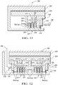
- Figure 12 illustrates an electric motor disconnect/pass through assembly, generally indicated at 300, somewhat similar to the assembly 200 of Figure 11 but also including a rotary input shaft 309 and a pair of previously described overrunning and control assemblies, generally indicated at 308.
- the assembly 300 also includes a motor stator 302, a motor rotor 304 and a rotary output shaft 306.
- Parts of each subassembly 308 which are the same or similar in structure and/or function to the parts shown in prior Figures 1-10 have the same reference number but are prefaced by the number "3.” In other words "300" has been added to the prior reference number.
- the magnetic field line plot also referred to as a magnetic flux line plot, shown in the cross sectional view of the subject linear motor structure, in Figure 13 .
- This is a circularly symmetric machine structure, with the translator axial movement direction shown in the x-direction, and the radial direction shown in the y-direction.
- the stator 24,28 cross section is a three iron tooth 72, two slot/coil 26 structure with the slot openings facing, across a radial air gap, the moving element or translator.
- the translator structure includes a single, axially-magnetized, rare earth PM ring 78 sandwiched between two iron field redirection rings 80. The sizing of the various components can be estimated from the scaling, given in meters, on the x and y axes.
- the magnetic field lines have been determined by a commercial magnetic finite element analysis (MFEA) software package.
- MFEA magnetic finite element analysis
- FIG. 15a A plot of the actual total axial force on the translator body as a function of axial position, given in Newtons, is shown in Figure 15a . If the translator is positioned to the right of center, it is pushed, due to its own magnetic field, to the right, and if positioned to the left of center, it is pushed further to the left. This is referred to as the "latching" action of the assembly.
- the exact center position, where the left-right pushing force exactly balances to zero, is an unstable equilibrium point, at which even minute movements will result in forces tending to push the translator away from the center position.
- the two other points shown, near the two axial ends of the stator structure, where the net translational force also passes through a zero value, are stable equilibrium points, where minute movements result in position restoring force production.
- the magnet axial magnetization is stipulated to be to the right, in the plus x-direction, and therefore the direction or polarity of the magnetic lines of force closed "flow" path, due to the magnet alone, would be a counter clockwise circulation.
- the polarity direction of the circulating magnetic lines of force due to an electric current is given by the "right hand rule.” If the thumb of one's right hand is made to point in the direction of the current flow in a wire, or a coil of wires, with the fingers encircling the cross section of the wire or the coil, the magnetic field lines or flux lines also encircle the wire or coil cross section and have a circulating direction in the same direction as the curling fingers.
- a slide show set of solutions for the total magnetic field lines within the linear motor structure with the same coil current drive as in the case shown in Figure 16 , as a function of the axial position of the translator, similar to that given for the previous case of magnet excitation alone, show that for the level of coil current assumed the net force on the translator structure is always to the left, no matter the assumed value of the translator position.
Landscapes
- Engineering & Computer Science (AREA)
- General Engineering & Computer Science (AREA)
- Mechanical Engineering (AREA)
- Physics & Mathematics (AREA)
- Electromagnetism (AREA)
- Reciprocating, Oscillating Or Vibrating Motors (AREA)
Claims (9)
- Schaltbare Linearaktuatorvorrichtung (10) zur Steuerung des Betriebsmodus einer Kupplungsanordnung (12), wobei die Vorrichtung eine Vielzahl von magnetischen Quellen (26, 30, 78) aufweist, die entsprechende magnetische Felder produzieren, um eine Nettotranslationskraft zu erzeugen, wobei die Vorrichtung Folgendes beinhaltet:eine Statorstruktur (24, 28), die mindestens eine elektromagnetische Quelle (26, 30) beinhaltet; undeine Umsetzerstruktur (38, 44), die eine Dauermagnetquelle (78) beinhaltet, die über einen radialen Luftspalt mit der Statorstruktur magnetisch verbunden und entlang einer Achse (18) zwischen ersten und zweiten stabilen axialen Endpositionen, die ersten und zweiten Betriebsmodi der Kupplungsanordnung entsprechen, für eine Translationsbewegung relativ zu der Statorstruktur abgestützt ist:
wobei die Dauermagnetquelle eine instabile axiale Gleichgewichtsposition zwischen den Endpositionen aufweist und wobei sich die Umsetzerstruktur entlang der Achse zwischen den verschiedenen Positionen umsetzt, wenn sie wahrnimmt, dass die Nettotranslationskraft eine erste Translationskraft umfasst, die durch Bestromung der mindestens einen elektromagnetischen Quelle verursacht wird, und eine Verriegelungskraft, basierend auf einer linearen Position der Dauermagnetquelle entlang der Achse; gekennzeichnet durch:
ein Führungselement (64', 64", 264, 364), angeordnet in dem radialen Luftspalt, dazu ausgelegt, die Bewegung zu führen. - Vorrichtung nach Anspruch 1, wobei die Strukturen (24, 28, 38, 44) im Wesentlichen kreisförmig symmetrisch sind.
- Vorrichtung nach Anspruch 1, wobei die Dauermagnetquelle (78) einen runden Magneten umfasst.
- Vorrichtung nach Anspruch 3, wobei der runde Magnet ein Seltenerdmagnet ist.
- Vorrichtung nach Anspruch 3, wobei der runde Magnet axial magnetisiert ist.
- Vorrichtung nach Anspruch 3, wobei die Umsetzerstruktur (38, 44) ein Paar von Feldumlenkungsringen (80) beinhaltet und wobei der runde Magnet zwischen den Feldumlenkungsringen sandwichartig positioniert ist.
- Vorrichtung nach Anspruch 2, wobei jede elektromagnetische Quelle einen ringförmigen Schlitz und eine in dem Schlitz angeordnete Spule (26, 30) beinhaltet, wobei sich jeder Schlitz zu dem radialen Luftspalt öffnet.
- Vorrichtung nach Anspruch 1, wobei die Dauermagnetquelle (78) ein Dauermagnetfeld aufweist und die mindestens eine elektromagnetische Quelle eine Spule (26, 30) beinhaltet und wobei Spulenbestromung ein zeitweiliges Magnetfeld erzeugt, das die Umsetzerstruktur (38, 44) veranlasst, sich entlang der Achse (18) umzusetzen, und wobei das Dauermagnetfeld die Umsetzerstruktur veranlasst, mindestens eine der Endpositionen beizubehalten, ohne dass es notwendig ist, eine Spulenbestromung beizubehalten, wobei ein Verriegelungseffekt bereitgestellt wird.
- Vorrichtung nach einem der vorangehenden Ansprüche, ferner umfassend einen Verbindungsstab (34, 40), wobei das Führungselement (64', 64", 264, 364) dazu ausgelegt ist, auch eine Bewegung des Verbindungsstabes zu führen.
Applications Claiming Priority (2)
| Application Number | Priority Date | Filing Date | Title |
|---|---|---|---|
| US201361882694P | 2013-09-26 | 2013-09-26 | |
| PCT/US2014/056716 WO2015047925A1 (en) | 2013-09-26 | 2014-09-22 | Apparatus for controlling operating modes of a coupling assembly, and electric motor disconnect and pass through assemblies |
Publications (3)
| Publication Number | Publication Date |
|---|---|
| EP3049685A1 EP3049685A1 (de) | 2016-08-03 |
| EP3049685A4 EP3049685A4 (de) | 2017-06-28 |
| EP3049685B1 true EP3049685B1 (de) | 2019-10-30 |
Family
ID=52744370
Family Applications (1)
| Application Number | Title | Priority Date | Filing Date |
|---|---|---|---|
| EP14847768.0A Active EP3049685B1 (de) | 2013-09-26 | 2014-09-22 | Vorrichtung zur steuerung von betriebsmodi einer kupplungsanordnung sowie elektromotorabschalt- und -durchgangsanordnungen |
Country Status (2)
| Country | Link |
|---|---|
| EP (1) | EP3049685B1 (de) |
| WO (1) | WO2015047925A1 (de) |
Families Citing this family (1)
| Publication number | Priority date | Publication date | Assignee | Title |
|---|---|---|---|---|
| US10995803B2 (en) * | 2018-12-04 | 2021-05-04 | Means Industries, Inc. | Electromagnetic system for controlling the operating mode of a non friction coupling assembly and coupling and magnetic control assembly having same |
Family Cites Families (6)
| Publication number | Priority date | Publication date | Assignee | Title |
|---|---|---|---|---|
| US2863326A (en) * | 1954-05-20 | 1958-12-09 | Ferodo Sa | Electrocentrifugal clutches |
| JPH0359530U (de) * | 1989-10-13 | 1991-06-12 | ||
| JP2001347959A (ja) * | 2000-06-06 | 2001-12-18 | Mitsubishi Electric Corp | 電動パワーステアリング装置 |
| US8276725B2 (en) * | 2009-07-20 | 2012-10-02 | GM Global Technology Operations LC | Selectable one-way clutch |
| US8646587B2 (en) * | 2010-12-10 | 2014-02-11 | Means Industries, Inc. | Strut for a controllable one-way clutch |
| JP6021229B2 (ja) * | 2011-02-14 | 2016-11-09 | ミーンズ インダストリーズ,インク. | 連結装置の動作モードを制御する電気機械アセンブリー |
-
2014
- 2014-09-22 EP EP14847768.0A patent/EP3049685B1/de active Active
- 2014-09-22 WO PCT/US2014/056716 patent/WO2015047925A1/en active Application Filing
Non-Patent Citations (1)
| Title |
|---|
| None * |
Also Published As
| Publication number | Publication date |
|---|---|
| EP3049685A4 (de) | 2017-06-28 |
| EP3049685A1 (de) | 2016-08-03 |
| WO2015047925A1 (en) | 2015-04-02 |
Similar Documents
| Publication | Publication Date | Title |
|---|---|---|
| US9435387B2 (en) | Device and apparatus for controlling the operating mode of a coupling assembly, coupling and control assembly and electric motor disconnect and pass through assemblies | |
| US10619681B2 (en) | Overrunning, non-friction coupling and control assemblies and switchable linear actuator device and reciprocating electromechanical apparatus for use therein | |
| US10533618B2 (en) | Overrunning, non-friction coupling and control assembly, engageable coupling assembly and locking member for use in the assemblies | |
| US11035423B2 (en) | Non-friction coupling and control assembly, engageable coupling assembly and locking member for use in the assemblies | |
| US9303699B2 (en) | Electromechanical assembly to control the operating mode of a coupling apparatus | |
| US8646587B2 (en) | Strut for a controllable one-way clutch | |
| US8813929B2 (en) | Controllable coupling assembly | |
| US10590999B2 (en) | Overrunning, non-friction, radial coupling and control assembly and switchable linear actuator device for use in the assembly | |
| US9377061B2 (en) | Electromagnetic system for controlling the operating mode of an overrunning coupling assembly and overrunning coupling and control assembly including the system | |
| JP6021229B2 (ja) | 連結装置の動作モードを制御する電気機械アセンブリー | |
| EP3577362B1 (de) | Hin- und hergehender elektromechanischer apparat | |
| US11953060B2 (en) | Coupling and control assembly | |
| WO2020117880A1 (en) | Electromagnetic system for controlling the operating mode of a non-friction coupling assembly and coupling and magnetic control assembly having same | |
| US10968964B2 (en) | Coupling and control assembly having an internal latching mechanism | |
| EP3049685B1 (de) | Vorrichtung zur steuerung von betriebsmodi einer kupplungsanordnung sowie elektromotorabschalt- und -durchgangsanordnungen | |
| CN113412205B (zh) | 非摩擦式耦合和控制组件、可接合的耦合组件和组件中使用的锁定构件 | |
| CN113251085A (zh) | 电动态联接和控制组件和其中使用的可切换的线性致动器装置 | |
| WO2015047938A1 (en) | Electromagnetic system for overrunning coupling assembly |
Legal Events
| Date | Code | Title | Description |
|---|---|---|---|
| PUAI | Public reference made under article 153(3) epc to a published international application that has entered the european phase |
Free format text: ORIGINAL CODE: 0009012 |
|
| 17P | Request for examination filed |
Effective date: 20160222 |
|
| AK | Designated contracting states |
Kind code of ref document: A1 Designated state(s): AL AT BE BG CH CY CZ DE DK EE ES FI FR GB GR HR HU IE IS IT LI LT LU LV MC MK MT NL NO PL PT RO RS SE SI SK SM TR |
|
| AX | Request for extension of the european patent |
Extension state: BA ME |
|
| DAX | Request for extension of the european patent (deleted) | ||
| A4 | Supplementary search report drawn up and despatched |
Effective date: 20170531 |
|
| RIC1 | Information provided on ipc code assigned before grant |
Ipc: F16D 41/12 20060101ALI20170524BHEP Ipc: F16D 27/10 20060101ALI20170524BHEP Ipc: F16D 41/16 20060101ALI20170524BHEP Ipc: F16D 11/00 20060101ALI20170524BHEP Ipc: F16D 27/02 20060101AFI20170524BHEP |
|
| STAA | Information on the status of an ep patent application or granted ep patent |
Free format text: STATUS: EXAMINATION IS IN PROGRESS |
|
| 17Q | First examination report despatched |
Effective date: 20180710 |
|
| GRAP | Despatch of communication of intention to grant a patent |
Free format text: ORIGINAL CODE: EPIDOSNIGR1 |
|
| STAA | Information on the status of an ep patent application or granted ep patent |
Free format text: STATUS: GRANT OF PATENT IS INTENDED |
|
| INTG | Intention to grant announced |
Effective date: 20190515 |
|
| GRAS | Grant fee paid |
Free format text: ORIGINAL CODE: EPIDOSNIGR3 |
|
| GRAA | (expected) grant |
Free format text: ORIGINAL CODE: 0009210 |
|
| STAA | Information on the status of an ep patent application or granted ep patent |
Free format text: STATUS: THE PATENT HAS BEEN GRANTED |
|
| AK | Designated contracting states |
Kind code of ref document: B1 Designated state(s): AL AT BE BG CH CY CZ DE DK EE ES FI FR GB GR HR HU IE IS IT LI LT LU LV MC MK MT NL NO PL PT RO RS SE SI SK SM TR |
|
| REG | Reference to a national code |
Ref country code: GB Ref legal event code: FG4D |
|
| REG | Reference to a national code |
Ref country code: CH Ref legal event code: EP |
|
| REG | Reference to a national code |
Ref country code: DE Ref legal event code: R096 Ref document number: 602014056072 Country of ref document: DE |
|
| REG | Reference to a national code |
Ref country code: AT Ref legal event code: REF Ref document number: 1196466 Country of ref document: AT Kind code of ref document: T Effective date: 20191115 |
|
| REG | Reference to a national code |
Ref country code: IE Ref legal event code: FG4D |
|
| REG | Reference to a national code |
Ref country code: LT Ref legal event code: MG4D |
|
| PG25 | Lapsed in a contracting state [announced via postgrant information from national office to epo] |
Ref country code: LT Free format text: LAPSE BECAUSE OF FAILURE TO SUBMIT A TRANSLATION OF THE DESCRIPTION OR TO PAY THE FEE WITHIN THE PRESCRIBED TIME-LIMIT Effective date: 20191030 Ref country code: LV Free format text: LAPSE BECAUSE OF FAILURE TO SUBMIT A TRANSLATION OF THE DESCRIPTION OR TO PAY THE FEE WITHIN THE PRESCRIBED TIME-LIMIT Effective date: 20191030 Ref country code: NL Free format text: LAPSE BECAUSE OF FAILURE TO SUBMIT A TRANSLATION OF THE DESCRIPTION OR TO PAY THE FEE WITHIN THE PRESCRIBED TIME-LIMIT Effective date: 20191030 Ref country code: SE Free format text: LAPSE BECAUSE OF FAILURE TO SUBMIT A TRANSLATION OF THE DESCRIPTION OR TO PAY THE FEE WITHIN THE PRESCRIBED TIME-LIMIT Effective date: 20191030 Ref country code: BG Free format text: LAPSE BECAUSE OF FAILURE TO SUBMIT A TRANSLATION OF THE DESCRIPTION OR TO PAY THE FEE WITHIN THE PRESCRIBED TIME-LIMIT Effective date: 20200130 Ref country code: FI Free format text: LAPSE BECAUSE OF FAILURE TO SUBMIT A TRANSLATION OF THE DESCRIPTION OR TO PAY THE FEE WITHIN THE PRESCRIBED TIME-LIMIT Effective date: 20191030 Ref country code: PT Free format text: LAPSE BECAUSE OF FAILURE TO SUBMIT A TRANSLATION OF THE DESCRIPTION OR TO PAY THE FEE WITHIN THE PRESCRIBED TIME-LIMIT Effective date: 20200302 Ref country code: NO Free format text: LAPSE BECAUSE OF FAILURE TO SUBMIT A TRANSLATION OF THE DESCRIPTION OR TO PAY THE FEE WITHIN THE PRESCRIBED TIME-LIMIT Effective date: 20200130 Ref country code: PL Free format text: LAPSE BECAUSE OF FAILURE TO SUBMIT A TRANSLATION OF THE DESCRIPTION OR TO PAY THE FEE WITHIN THE PRESCRIBED TIME-LIMIT Effective date: 20191030 Ref country code: GR Free format text: LAPSE BECAUSE OF FAILURE TO SUBMIT A TRANSLATION OF THE DESCRIPTION OR TO PAY THE FEE WITHIN THE PRESCRIBED TIME-LIMIT Effective date: 20200131 |
|
| REG | Reference to a national code |
Ref country code: NL Ref legal event code: MP Effective date: 20191030 |
|
| PG25 | Lapsed in a contracting state [announced via postgrant information from national office to epo] |
Ref country code: RS Free format text: LAPSE BECAUSE OF FAILURE TO SUBMIT A TRANSLATION OF THE DESCRIPTION OR TO PAY THE FEE WITHIN THE PRESCRIBED TIME-LIMIT Effective date: 20191030 Ref country code: IS Free format text: LAPSE BECAUSE OF FAILURE TO SUBMIT A TRANSLATION OF THE DESCRIPTION OR TO PAY THE FEE WITHIN THE PRESCRIBED TIME-LIMIT Effective date: 20200229 Ref country code: HR Free format text: LAPSE BECAUSE OF FAILURE TO SUBMIT A TRANSLATION OF THE DESCRIPTION OR TO PAY THE FEE WITHIN THE PRESCRIBED TIME-LIMIT Effective date: 20191030 |
|
| PG25 | Lapsed in a contracting state [announced via postgrant information from national office to epo] |
Ref country code: AL Free format text: LAPSE BECAUSE OF FAILURE TO SUBMIT A TRANSLATION OF THE DESCRIPTION OR TO PAY THE FEE WITHIN THE PRESCRIBED TIME-LIMIT Effective date: 20191030 |
|
| PG25 | Lapsed in a contracting state [announced via postgrant information from national office to epo] |
Ref country code: RO Free format text: LAPSE BECAUSE OF FAILURE TO SUBMIT A TRANSLATION OF THE DESCRIPTION OR TO PAY THE FEE WITHIN THE PRESCRIBED TIME-LIMIT Effective date: 20191030 Ref country code: CZ Free format text: LAPSE BECAUSE OF FAILURE TO SUBMIT A TRANSLATION OF THE DESCRIPTION OR TO PAY THE FEE WITHIN THE PRESCRIBED TIME-LIMIT Effective date: 20191030 Ref country code: ES Free format text: LAPSE BECAUSE OF FAILURE TO SUBMIT A TRANSLATION OF THE DESCRIPTION OR TO PAY THE FEE WITHIN THE PRESCRIBED TIME-LIMIT Effective date: 20191030 Ref country code: EE Free format text: LAPSE BECAUSE OF FAILURE TO SUBMIT A TRANSLATION OF THE DESCRIPTION OR TO PAY THE FEE WITHIN THE PRESCRIBED TIME-LIMIT Effective date: 20191030 Ref country code: DK Free format text: LAPSE BECAUSE OF FAILURE TO SUBMIT A TRANSLATION OF THE DESCRIPTION OR TO PAY THE FEE WITHIN THE PRESCRIBED TIME-LIMIT Effective date: 20191030 |
|
| REG | Reference to a national code |
Ref country code: DE Ref legal event code: R097 Ref document number: 602014056072 Country of ref document: DE |
|
| REG | Reference to a national code |
Ref country code: AT Ref legal event code: MK05 Ref document number: 1196466 Country of ref document: AT Kind code of ref document: T Effective date: 20191030 |
|
| PG25 | Lapsed in a contracting state [announced via postgrant information from national office to epo] |
Ref country code: IT Free format text: LAPSE BECAUSE OF FAILURE TO SUBMIT A TRANSLATION OF THE DESCRIPTION OR TO PAY THE FEE WITHIN THE PRESCRIBED TIME-LIMIT Effective date: 20191030 Ref country code: SK Free format text: LAPSE BECAUSE OF FAILURE TO SUBMIT A TRANSLATION OF THE DESCRIPTION OR TO PAY THE FEE WITHIN THE PRESCRIBED TIME-LIMIT Effective date: 20191030 Ref country code: SM Free format text: LAPSE BECAUSE OF FAILURE TO SUBMIT A TRANSLATION OF THE DESCRIPTION OR TO PAY THE FEE WITHIN THE PRESCRIBED TIME-LIMIT Effective date: 20191030 |
|
| PLBE | No opposition filed within time limit |
Free format text: ORIGINAL CODE: 0009261 |
|
| STAA | Information on the status of an ep patent application or granted ep patent |
Free format text: STATUS: NO OPPOSITION FILED WITHIN TIME LIMIT |
|
| 26N | No opposition filed |
Effective date: 20200731 |
|
| PG25 | Lapsed in a contracting state [announced via postgrant information from national office to epo] |
Ref country code: SI Free format text: LAPSE BECAUSE OF FAILURE TO SUBMIT A TRANSLATION OF THE DESCRIPTION OR TO PAY THE FEE WITHIN THE PRESCRIBED TIME-LIMIT Effective date: 20191030 Ref country code: AT Free format text: LAPSE BECAUSE OF FAILURE TO SUBMIT A TRANSLATION OF THE DESCRIPTION OR TO PAY THE FEE WITHIN THE PRESCRIBED TIME-LIMIT Effective date: 20191030 |
|
| PG25 | Lapsed in a contracting state [announced via postgrant information from national office to epo] |
Ref country code: MC Free format text: LAPSE BECAUSE OF FAILURE TO SUBMIT A TRANSLATION OF THE DESCRIPTION OR TO PAY THE FEE WITHIN THE PRESCRIBED TIME-LIMIT Effective date: 20191030 |
|
| REG | Reference to a national code |
Ref country code: CH Ref legal event code: PL |
|
| GBPC | Gb: european patent ceased through non-payment of renewal fee |
Effective date: 20200922 |
|
| REG | Reference to a national code |
Ref country code: BE Ref legal event code: MM Effective date: 20200930 |
|
| PG25 | Lapsed in a contracting state [announced via postgrant information from national office to epo] |
Ref country code: LU Free format text: LAPSE BECAUSE OF NON-PAYMENT OF DUE FEES Effective date: 20200922 |
|
| PG25 | Lapsed in a contracting state [announced via postgrant information from national office to epo] |
Ref country code: FR Free format text: LAPSE BECAUSE OF NON-PAYMENT OF DUE FEES Effective date: 20200930 |
|
| PG25 | Lapsed in a contracting state [announced via postgrant information from national office to epo] |
Ref country code: IE Free format text: LAPSE BECAUSE OF NON-PAYMENT OF DUE FEES Effective date: 20200922 Ref country code: LI Free format text: LAPSE BECAUSE OF NON-PAYMENT OF DUE FEES Effective date: 20200930 Ref country code: GB Free format text: LAPSE BECAUSE OF NON-PAYMENT OF DUE FEES Effective date: 20200922 Ref country code: CH Free format text: LAPSE BECAUSE OF NON-PAYMENT OF DUE FEES Effective date: 20200930 Ref country code: BE Free format text: LAPSE BECAUSE OF NON-PAYMENT OF DUE FEES Effective date: 20200930 |
|
| PG25 | Lapsed in a contracting state [announced via postgrant information from national office to epo] |
Ref country code: TR Free format text: LAPSE BECAUSE OF FAILURE TO SUBMIT A TRANSLATION OF THE DESCRIPTION OR TO PAY THE FEE WITHIN THE PRESCRIBED TIME-LIMIT Effective date: 20191030 Ref country code: MT Free format text: LAPSE BECAUSE OF FAILURE TO SUBMIT A TRANSLATION OF THE DESCRIPTION OR TO PAY THE FEE WITHIN THE PRESCRIBED TIME-LIMIT Effective date: 20191030 Ref country code: CY Free format text: LAPSE BECAUSE OF FAILURE TO SUBMIT A TRANSLATION OF THE DESCRIPTION OR TO PAY THE FEE WITHIN THE PRESCRIBED TIME-LIMIT Effective date: 20191030 |
|
| PG25 | Lapsed in a contracting state [announced via postgrant information from national office to epo] |
Ref country code: MK Free format text: LAPSE BECAUSE OF FAILURE TO SUBMIT A TRANSLATION OF THE DESCRIPTION OR TO PAY THE FEE WITHIN THE PRESCRIBED TIME-LIMIT Effective date: 20191030 |
|
| PGFP | Annual fee paid to national office [announced via postgrant information from national office to epo] |
Ref country code: DE Payment date: 20230822 Year of fee payment: 10 |