EP3049640B1 - Protection thermique de joint d'étanchéité à l'air externe d'aube (boas) - Google Patents
Protection thermique de joint d'étanchéité à l'air externe d'aube (boas) Download PDFInfo
- Publication number
- EP3049640B1 EP3049640B1 EP14845261.8A EP14845261A EP3049640B1 EP 3049640 B1 EP3049640 B1 EP 3049640B1 EP 14845261 A EP14845261 A EP 14845261A EP 3049640 B1 EP3049640 B1 EP 3049640B1
- Authority
- EP
- European Patent Office
- Prior art keywords
- vane
- edge face
- ejection ports
- passages
- trailing edge
- Prior art date
- Legal status (The legal status is an assumption and is not a legal conclusion. Google has not performed a legal analysis and makes no representation as to the accuracy of the status listed.)
- Active
Links
- 241000270299 Boa Species 0.000 title 1
- 238000001816 cooling Methods 0.000 claims description 43
- 239000002826 coolant Substances 0.000 claims description 42
- 238000000034 method Methods 0.000 claims description 6
- 238000009828 non-uniform distribution Methods 0.000 claims description 2
- 239000007789 gas Substances 0.000 description 13
- 239000000567 combustion gas Substances 0.000 description 12
- 239000012530 fluid Substances 0.000 description 9
- 239000000446 fuel Substances 0.000 description 6
- 230000009429 distress Effects 0.000 description 4
- 238000003754 machining Methods 0.000 description 4
- VYPSYNLAJGMNEJ-UHFFFAOYSA-N Silicium dioxide Chemical compound O=[Si]=O VYPSYNLAJGMNEJ-UHFFFAOYSA-N 0.000 description 3
- 230000008901 benefit Effects 0.000 description 3
- 230000003071 parasitic effect Effects 0.000 description 3
- 230000009467 reduction Effects 0.000 description 3
- 230000001154 acute effect Effects 0.000 description 2
- 238000009826 distribution Methods 0.000 description 2
- 230000037406 food intake Effects 0.000 description 2
- 230000003068 static effect Effects 0.000 description 2
- PNEYBMLMFCGWSK-UHFFFAOYSA-N aluminium oxide Chemical group [O-2].[O-2].[O-2].[Al+3].[Al+3] PNEYBMLMFCGWSK-UHFFFAOYSA-N 0.000 description 1
- 238000005266 casting Methods 0.000 description 1
- 230000008859 change Effects 0.000 description 1
- 238000004891 communication Methods 0.000 description 1
- 230000006835 compression Effects 0.000 description 1
- 238000007906 compression Methods 0.000 description 1
- 239000012141 concentrate Substances 0.000 description 1
- 238000012937 correction Methods 0.000 description 1
- 230000001419 dependent effect Effects 0.000 description 1
- 238000013461 design Methods 0.000 description 1
- 238000005553 drilling Methods 0.000 description 1
- 230000007613 environmental effect Effects 0.000 description 1
- 239000000284 extract Substances 0.000 description 1
- 239000000463 material Substances 0.000 description 1
- 230000007246 mechanism Effects 0.000 description 1
- 238000012986 modification Methods 0.000 description 1
- 230000004048 modification Effects 0.000 description 1
- 239000003870 refractory metal Substances 0.000 description 1
- 230000004044 response Effects 0.000 description 1
- 239000004576 sand Substances 0.000 description 1
- 239000000377 silicon dioxide Substances 0.000 description 1
- 239000000126 substance Substances 0.000 description 1
- 238000011144 upstream manufacturing Methods 0.000 description 1
- XLYOFNOQVPJJNP-UHFFFAOYSA-N water Substances O XLYOFNOQVPJJNP-UHFFFAOYSA-N 0.000 description 1
Images


Classifications
-
- F—MECHANICAL ENGINEERING; LIGHTING; HEATING; WEAPONS; BLASTING
- F01—MACHINES OR ENGINES IN GENERAL; ENGINE PLANTS IN GENERAL; STEAM ENGINES
- F01D—NON-POSITIVE DISPLACEMENT MACHINES OR ENGINES, e.g. STEAM TURBINES
- F01D9/00—Stators
- F01D9/02—Nozzles; Nozzle boxes; Stator blades; Guide conduits, e.g. individual nozzles
- F01D9/04—Nozzles; Nozzle boxes; Stator blades; Guide conduits, e.g. individual nozzles forming ring or sector
- F01D9/041—Nozzles; Nozzle boxes; Stator blades; Guide conduits, e.g. individual nozzles forming ring or sector using blades
-
- F—MECHANICAL ENGINEERING; LIGHTING; HEATING; WEAPONS; BLASTING
- F01—MACHINES OR ENGINES IN GENERAL; ENGINE PLANTS IN GENERAL; STEAM ENGINES
- F01D—NON-POSITIVE DISPLACEMENT MACHINES OR ENGINES, e.g. STEAM TURBINES
- F01D11/00—Preventing or minimising internal leakage of working-fluid, e.g. between stages
- F01D11/08—Preventing or minimising internal leakage of working-fluid, e.g. between stages for sealing space between rotor blade tips and stator
- F01D11/14—Adjusting or regulating tip-clearance, i.e. distance between rotor-blade tips and stator casing
- F01D11/20—Actively adjusting tip-clearance
- F01D11/24—Actively adjusting tip-clearance by selectively cooling-heating stator or rotor components
-
- F—MECHANICAL ENGINEERING; LIGHTING; HEATING; WEAPONS; BLASTING
- F01—MACHINES OR ENGINES IN GENERAL; ENGINE PLANTS IN GENERAL; STEAM ENGINES
- F01D—NON-POSITIVE DISPLACEMENT MACHINES OR ENGINES, e.g. STEAM TURBINES
- F01D11/00—Preventing or minimising internal leakage of working-fluid, e.g. between stages
- F01D11/08—Preventing or minimising internal leakage of working-fluid, e.g. between stages for sealing space between rotor blade tips and stator
-
- F—MECHANICAL ENGINEERING; LIGHTING; HEATING; WEAPONS; BLASTING
- F01—MACHINES OR ENGINES IN GENERAL; ENGINE PLANTS IN GENERAL; STEAM ENGINES
- F01D—NON-POSITIVE DISPLACEMENT MACHINES OR ENGINES, e.g. STEAM TURBINES
- F01D5/00—Blades; Blade-carrying members; Heating, heat-insulating, cooling or antivibration means on the blades or the members
- F01D5/02—Blade-carrying members, e.g. rotors
-
- F—MECHANICAL ENGINEERING; LIGHTING; HEATING; WEAPONS; BLASTING
- F02—COMBUSTION ENGINES; HOT-GAS OR COMBUSTION-PRODUCT ENGINE PLANTS
- F02C—GAS-TURBINE PLANTS; AIR INTAKES FOR JET-PROPULSION PLANTS; CONTROLLING FUEL SUPPLY IN AIR-BREATHING JET-PROPULSION PLANTS
- F02C3/00—Gas-turbine plants characterised by the use of combustion products as the working fluid
- F02C3/04—Gas-turbine plants characterised by the use of combustion products as the working fluid having a turbine driving a compressor
-
- F—MECHANICAL ENGINEERING; LIGHTING; HEATING; WEAPONS; BLASTING
- F04—POSITIVE - DISPLACEMENT MACHINES FOR LIQUIDS; PUMPS FOR LIQUIDS OR ELASTIC FLUIDS
- F04D—NON-POSITIVE-DISPLACEMENT PUMPS
- F04D29/00—Details, component parts, or accessories
- F04D29/26—Rotors specially for elastic fluids
- F04D29/32—Rotors specially for elastic fluids for axial flow pumps
- F04D29/321—Rotors specially for elastic fluids for axial flow pumps for axial flow compressors
-
- F—MECHANICAL ENGINEERING; LIGHTING; HEATING; WEAPONS; BLASTING
- F04—POSITIVE - DISPLACEMENT MACHINES FOR LIQUIDS; PUMPS FOR LIQUIDS OR ELASTIC FLUIDS
- F04D—NON-POSITIVE-DISPLACEMENT PUMPS
- F04D29/00—Details, component parts, or accessories
- F04D29/40—Casings; Connections of working fluid
- F04D29/52—Casings; Connections of working fluid for axial pumps
- F04D29/54—Fluid-guiding means, e.g. diffusers
- F04D29/541—Specially adapted for elastic fluid pumps
- F04D29/542—Bladed diffusers
-
- F—MECHANICAL ENGINEERING; LIGHTING; HEATING; WEAPONS; BLASTING
- F04—POSITIVE - DISPLACEMENT MACHINES FOR LIQUIDS; PUMPS FOR LIQUIDS OR ELASTIC FLUIDS
- F04D—NON-POSITIVE-DISPLACEMENT PUMPS
- F04D29/00—Details, component parts, or accessories
- F04D29/58—Cooling; Heating; Diminishing heat transfer
- F04D29/582—Cooling; Heating; Diminishing heat transfer specially adapted for elastic fluid pumps
- F04D29/584—Cooling; Heating; Diminishing heat transfer specially adapted for elastic fluid pumps cooling or heating the machine
-
- F—MECHANICAL ENGINEERING; LIGHTING; HEATING; WEAPONS; BLASTING
- F05—INDEXING SCHEMES RELATING TO ENGINES OR PUMPS IN VARIOUS SUBCLASSES OF CLASSES F01-F04
- F05D—INDEXING SCHEME FOR ASPECTS RELATING TO NON-POSITIVE-DISPLACEMENT MACHINES OR ENGINES, GAS-TURBINES OR JET-PROPULSION PLANTS
- F05D2220/00—Application
- F05D2220/30—Application in turbines
- F05D2220/32—Application in turbines in gas turbines
-
- F—MECHANICAL ENGINEERING; LIGHTING; HEATING; WEAPONS; BLASTING
- F05—INDEXING SCHEMES RELATING TO ENGINES OR PUMPS IN VARIOUS SUBCLASSES OF CLASSES F01-F04
- F05D—INDEXING SCHEME FOR ASPECTS RELATING TO NON-POSITIVE-DISPLACEMENT MACHINES OR ENGINES, GAS-TURBINES OR JET-PROPULSION PLANTS
- F05D2240/00—Components
- F05D2240/10—Stators
- F05D2240/11—Shroud seal segments
-
- F—MECHANICAL ENGINEERING; LIGHTING; HEATING; WEAPONS; BLASTING
- F05—INDEXING SCHEMES RELATING TO ENGINES OR PUMPS IN VARIOUS SUBCLASSES OF CLASSES F01-F04
- F05D—INDEXING SCHEME FOR ASPECTS RELATING TO NON-POSITIVE-DISPLACEMENT MACHINES OR ENGINES, GAS-TURBINES OR JET-PROPULSION PLANTS
- F05D2240/00—Components
- F05D2240/10—Stators
- F05D2240/12—Fluid guiding means, e.g. vanes
-
- F—MECHANICAL ENGINEERING; LIGHTING; HEATING; WEAPONS; BLASTING
- F05—INDEXING SCHEMES RELATING TO ENGINES OR PUMPS IN VARIOUS SUBCLASSES OF CLASSES F01-F04
- F05D—INDEXING SCHEME FOR ASPECTS RELATING TO NON-POSITIVE-DISPLACEMENT MACHINES OR ENGINES, GAS-TURBINES OR JET-PROPULSION PLANTS
- F05D2240/00—Components
- F05D2240/35—Combustors or associated equipment
-
- F—MECHANICAL ENGINEERING; LIGHTING; HEATING; WEAPONS; BLASTING
- F05—INDEXING SCHEMES RELATING TO ENGINES OR PUMPS IN VARIOUS SUBCLASSES OF CLASSES F01-F04
- F05D—INDEXING SCHEME FOR ASPECTS RELATING TO NON-POSITIVE-DISPLACEMENT MACHINES OR ENGINES, GAS-TURBINES OR JET-PROPULSION PLANTS
- F05D2240/00—Components
- F05D2240/80—Platforms for stationary or moving blades
- F05D2240/81—Cooled platforms
-
- F—MECHANICAL ENGINEERING; LIGHTING; HEATING; WEAPONS; BLASTING
- F05—INDEXING SCHEMES RELATING TO ENGINES OR PUMPS IN VARIOUS SUBCLASSES OF CLASSES F01-F04
- F05D—INDEXING SCHEME FOR ASPECTS RELATING TO NON-POSITIVE-DISPLACEMENT MACHINES OR ENGINES, GAS-TURBINES OR JET-PROPULSION PLANTS
- F05D2250/00—Geometry
- F05D2250/10—Two-dimensional
- F05D2250/12—Two-dimensional rectangular
-
- F—MECHANICAL ENGINEERING; LIGHTING; HEATING; WEAPONS; BLASTING
- F05—INDEXING SCHEMES RELATING TO ENGINES OR PUMPS IN VARIOUS SUBCLASSES OF CLASSES F01-F04
- F05D—INDEXING SCHEME FOR ASPECTS RELATING TO NON-POSITIVE-DISPLACEMENT MACHINES OR ENGINES, GAS-TURBINES OR JET-PROPULSION PLANTS
- F05D2260/00—Function
- F05D2260/20—Heat transfer, e.g. cooling
- F05D2260/201—Heat transfer, e.g. cooling by impingement of a fluid
-
- Y—GENERAL TAGGING OF NEW TECHNOLOGICAL DEVELOPMENTS; GENERAL TAGGING OF CROSS-SECTIONAL TECHNOLOGIES SPANNING OVER SEVERAL SECTIONS OF THE IPC; TECHNICAL SUBJECTS COVERED BY FORMER USPC CROSS-REFERENCE ART COLLECTIONS [XRACs] AND DIGESTS
- Y02—TECHNOLOGIES OR APPLICATIONS FOR MITIGATION OR ADAPTATION AGAINST CLIMATE CHANGE
- Y02T—CLIMATE CHANGE MITIGATION TECHNOLOGIES RELATED TO TRANSPORTATION
- Y02T50/00—Aeronautics or air transport
- Y02T50/60—Efficient propulsion technologies, e.g. for aircraft
Definitions
- This disclosure relates to a gas turbine engine, and more particularly to a vane for cooling thermal protection of a blade outer air seal (BOAS).
- BOAS blade outer air seal
- Gas turbine engines typically include a compressor section, a combustor section and a turbine section. During operation, air is pressurized in the compressor section and is mixed with fuel and burned in the combustor section to generate hot combustion gases. The hot combustion gases are communicated through the turbine section, which extracts energy from the hot combustion gases to power the compressor section and other gas turbine engine loads.
- a typical turbine section includes at least one array of stator vanes and one array of BOAS each arranged circumferentially about an engine central longitudinal axis to define an outer radial flow path boundary for the hot combustion gases passing across exposed surfaces of the BOAS.
- the BOAS are prone to thermal distress due to the hot combustion gases.
- Each of the stator vanes includes an airfoil which communicates a relatively high pressure fluid downstream of the airfoil and onto an exposed surface of one of the BOAS, making a portion of the exposed surface especially prone to thermal distress.
- BOAS are cooled by communicating bleed air from the compressor section to an inner plenum of the BOAS, which results in a parasitic loss due to gases being heated by the compressor section but not being combusted.
- the BOAS are cooled along the entire circumferential direction because the relative circumferential position of each of the upstream vane airfoil segments and relative position of combustor fuel nozzle locations may be unknown. Accordingly, a localized cooling feature is desirable to minimize parasitic losses.
- US 4522557 A discloses a prior art valve as set forth in the preamble of claim 1.
- the platform includes two or more ejection ports each connected to a common one of the at least one passage.
- the localized cooling region is evenly distributed about the cooling plane.
- each of the localized concentration and the total concentration is defined as a total cross-sectional area of the at least one ejection port located in a respective one of the localized cooling region and the trailing edge face.
- each surface of the trailing edge face adjacent the localized cooling region is free of any of the at least one ejection port.
- the edge face includes a non-uniform distribution of the at least one ejection port across a span between the lateral faces.
- the passage is configured to eject coolant in a direction that impinges an exposed surface of a blade outer air seal.
- the at least one passage defines a coolant axis perpendicular to the edge face.
- the at least one passage defines a coolant axis intersecting the edge face at an acute angle.
- the at least one ejection port defines a rectangular cross section.
- each of the platforms defines a first width and each of the blade outer air seals defines a second width different from the first width, each of the first and second widths extending in a circumferential direction about the engine axis.
- the turbine section includes a first quantity of the airfoil and a second quantity of the blade outer air seals different from the first quantity.
- each of the blade outer air seals is positioned downstream from one of the stator vanes with respect to the flow path.
- the exposed surface is a localized cooling area spaced a distance from spaced apart lateral edges of the blade outer air seals.
- the targeted region is located adjacent to an airfoil of the stator vane.
- FIG. 1 schematically illustrates a gas turbine engine 20.
- the gas turbine engine 20 is disclosed herein as a two-spool turbofan that generally incorporates a fan section 22, a compressor section 24, a combustor section 26 and a turbine section 28.
- Alternative engines might include an augmentor section (not shown) among other systems or features.
- the fan section 22 drives air along a bypass flow path B in a bypass duct defined within a nacelle 15, while the compressor section 24 drives air along a core flow path C for compression and communication into the combustor section 26 then expansion through the turbine section 28.
- the exemplary engine 20 generally includes a low speed spool 30 and a high speed spool 32 mounted for rotation about an engine central longitudinal axis A relative to an engine static structure 36 via several bearing systems 38. It should be understood that various bearing systems 38 at various locations may alternatively or additionally be provided, and the location of bearing systems 38 may be varied as appropriate to the application.
- the low speed spool 30 generally includes an inner shaft 40 that interconnects a fan 42, a low pressure compressor 44 and a low pressure turbine 46.
- the inner shaft 40 is connected to the fan 42 through a speed change mechanism, which in exemplary gas turbine engine 20 is illustrated as a geared architecture 48 to drive the fan 42 at a lower speed than the low speed spool 30.
- the high speed spool 32 includes an outer shaft 50 that interconnects a high pressure compressor 52 and high pressure turbine 54.
- a combustor 56 is arranged in exemplary gas turbine 20 between the high pressure compressor 52 and the high pressure turbine 54.
- a mid-turbine frame 57 of the engine static structure 36 is arranged generally between the high pressure turbine 54 and the low pressure turbine 46.
- the mid-turbine frame 57 further supports bearing systems 38 in the turbine section 28.
- the inner shaft 40 and the outer shaft 50 are concentric and rotate via bearing systems 38 about the engine central longitudinal axis A which is collinear with their longitudinal axes.
- the core airflow is compressed by the low pressure compressor 44 then the high pressure compressor 52, mixed and burned with fuel in the combustor 56, then expanded over the high pressure turbine 54 and low pressure turbine 46.
- the mid-turbine frame 57 includes airfoils 59 which are in the core airflow path C.
- the turbines 46, 54 rotationally drive the respective low speed spool 30 and high speed spool 32 in response to the expansion.
- gear system 50 may be located aft of combustor section 26 or even aft of turbine section 28, and fan section 22 may be positioned forward or aft of the location of gear system 48.
- the engine 20 in one example is a high-bypass geared aircraft engine.
- the engine 20 bypass ratio is greater than about six, with an example embodiment being greater than about ten
- the geared architecture 48 is an epicyclic gear train, such as a planetary gear system or other gear system, with a gear reduction ratio of greater than about 2.3 and the low pressure turbine 46 has a pressure ratio that is greater than about five.
- the engine 20 bypass ratio is greater than about ten
- the fan diameter is significantly larger than that of the low pressure compressor 44
- the low pressure turbine 46 has a pressure ratio that is greater than about five.
- Low pressure turbine 46 pressure ratio is pressure measured prior to inlet of low pressure turbine 46 as related to the pressure at the outlet of the low pressure turbine 46 prior to an exhaust nozzle.
- the geared architecture 48 may be an epicycle gear train, such as a planetary gear system or other gear system, with a gear reduction ratio of greater than about 2.3:1. It should be understood, however, that the above parameters are only exemplary of one embodiment of a geared architecture engine and that the present invention is applicable to other gas turbine engines including direct drive turbofans.
- the fan section 22 of the engine 20 is designed for a particular flight condition -- typically cruise at about 0.8 Mach and about 35,000 feet (10,668 m).
- the flight condition of 0.8 Mach and 35,000 ft (10,668 m), with the engine at its best fuel consumption - also known as "bucket cruise Thrust Specific Fuel Consumption ('TSFC')" - is the industry standard parameter of lbm of fuel being burned divided by lbf of thrust the engine produces at that minimum point.
- "Low fan pressure ratio” is the pressure ratio across the fan blade alone, without a Fan Exit Guide Vane (“FEGV”) system.
- the low fan pressure ratio as disclosed herein according to one non-limiting embodiment is less than about 1.45.
- the "Low corrected fan tip speed" as disclosed herein according to one non-limiting embodiment is less than about 1150 ft / second (350.5 m/s).
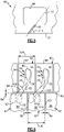
- FIG. 2 illustrates a highly schematic view of a vane and blade outer air seal (BOAS) for a gas turbine engine 20.
- the vane is a stator vane 60 for a turbine section 28.
- the stator vane 60 can be located in at least one of the low pressure turbine and high pressure turbine sections 46, 54, and an intermediate pressure turbine section of a three-spool engine.
- other types of vanes, other components arranged downstream from an airfoil, other parts of the gas turbine engine 20, and other systems such as ground based systems can benefit from the examples disclosed herein which are not limited to the design shown.
- the turbine section 28 includes at least one array of stator vanes 60 and at least one array of BOAS 62 each arranged circumferentially about an engine axis A to define an outer radial flow path boundary for a core flow path C.
- Each of the stator vanes 60 includes an outer platform 66 and an inner platform 67 spaced apart from each other in the radial direction with respect to the engine axis A.
- the platform 66 extends between a leading edge face 68 and a trailing edge face 70 spaced apart from each other in the axial direction along the engine axis A, and also between a pair of lateral mate faces 72 spaced apart from each other circumferentially.
- An airfoil 74 extends in the radial direction between the platforms 66, 67 to direct flow of hot combustion gases along the core flow path C.
- the airfoil 74 defines a leading edge 80 and a trailing edge 82 spaced apart from each other in a chordwise direction.
- the airfoil 74 defines a pressure side 76 and a suction side 78 (shown in Figure 6 ).
- the stator vanes 60 and BOAS 62 can be spaced apart from each other in the axial direction along the engine axis A to define a chordal seal region 84. Also, each of the BOAS 62 can be spaced apart from each other circumferentially to define an intersegment gap 86 therebetween (shown in Figure 6 ). Each of the BOAS 62 includes an exposed surface 88 spaced apart radially from a tip 65 of a rotor blade 64. In one example, each of the BOAS 62 defines a chamfer 90 adjacent to the exposed surface 88 to redirect fluids from the chordal seal region 84.
- each outer platform 66 defines one or more passages 92 configured to eject coolant in a direction that impinges the exposed surface 88 of one of the BOAS 62. The coolant reduces the temperature of a portion of the exposed surface 88 and surrounding portions of the BOAS 62.
- each of the passages 92 opens to the trailing edge face 70 of the platform 66.
- the outer platform 66 defines at least one passage 92 opening to the leading edge face 68 of the outer platform 66.
- the outer platform 66 defines one or more passages 92 opening to the trailing edge face 70 and the leading edge face 68.
- a coolant source 96 (shown schematically) communicates coolant to a plenum 94 defined by the outer platform 66.
- the coolant source 96 is the compressor section 24 which communicates bleed air to the plenum 94.
- the bleed air is at a lower temperature relative to the hot combustion gases adjacent to the exposed surface 88.
- other coolant sources are contemplated, including an auxiliary cooling source and other components of the aircraft.
- a coolant source can also provide leakage air to each chordal seal region 84 and intersegment gap 86 to cool the areas of the BOAS 62.
- the passages 92 can be configured to direct relatively high pressure coolant from the leading edge face 68 of the stator vane 60 to a rear face 87 of the BOAS 62 to prevent ingestion of relatively low pressure hot combustion gases into the chordal seal region 84.
- various geometries and locations of the plenum 94 with respect to the vane 60 are contemplated.
- the plenum 94 can also provide coolant to various components of the stator vanes 60, including convection cooling of the outer platform 66 and impingement cooling of internal surfaces of the stator vanes 60.
- the platform 66 defines one or more ejection ports 98 connected to at least one of the passages 92 (shown in Figures 2 and 5 ).
- the platform 66 defines at least two ejection ports 98 each connected to a common one of the passages 92.
- the trailing edge face 70 can include the ejection ports 98.
- the leading edge face 68 can also include one or more ejection ports 98.
- Each of the ejection ports 98 can have various geometries.
- the ejection ports 98 include a generally circular cross section (shown in Figure 4A ).
- the ejection ports 98 include a rectangular cross section or slot (shown in Figures 4B and 4C ).
- the trailing edge face 70 includes a plurality of passages 92 and ejection ports 98 (shown in Figures 2 , 4A and 4B ).
- trailing edge face 70 includes one passage 92 and one ejection port 98 (shown in Figure 4C ).
- the passages 92 and ejection ports 98 can each include a uniform area along a coolant axis 112 (shown in Figure 5 ).
- the passages 92 and ejection ports 98 can each be diffused in a convergent or divergent manner along the coolant axis 112.
- the passages 92 and ejection ports 98 can each include an elliptical configuration consisting of a minor and major axis of any size or proportion along the coolant axis 112.
- a length of each of the passages 92 includes the same cross sectional geometry as the respective one of the ejection ports 98.
- a length of each of the passages 92 can include a different cross sectional geometry as the respective one of the ejection ports 98. It should be understood that the passages 92 can be arranged in combination with ejection ports 98 having the same or different geometries, including any of the various geometries described herein.
- the ejections ports 98 define a localized cooling region 99 from which the coolant is ejected from the passages 92.
- the localized cooling region 99 is configured such that a localized concentration of ejection ports 98 in the localized cooling region 99 is greater than a total concentration of the ejection ports in the trailing edge face 70.
- the trailing edge face 70 adjacent to the localized cooling region 99 is free of any ejection ports.
- Concentration can be defined as a total cross-sectional area of the ejection ports 98 located in the respective one of localized cooling region 99 and the trailing edge face 70. In another example, concentration can be based upon a volume or pressure of coolant ejected from the respective one of localized cooling region 99 and the trailing edge face 70.
- the localized cooling region 99 is positioned with respect to the arrangement of the airfoil 74.
- the hot combustion gas flow along the core flow path C separate at the leading edge 80 along the pressure side 76 and suction side 78 of the airfoil 74 and rejoin at the trailing edge 82.
- the airfoil 74 generates a relatively high pressure fluid defined by a vector 108 extending in a direction downstream from the trailing edge 82 of the airfoil 74.
- the relatively high pressure fluid is communicated onto a portion of the exposed surface 88 of a downstream one of the BOAS 62.
- a targeted region 110 of the exposed surface 88 receiving the relatively high pressure fluid is subjected to a relatively higher temperature than surrounding areas of the BOAS 62.
- the localized cooling region 99 is positioned about a cooling plane 102 extending from the trailing edge face 70 in the direction of the vector 108. In some examples, the localized cooling region 99 is evenly distributed about the cooling plane 102 circumferentially across a distance 100 between the lateral mate faces 72. In other examples, the localized cooling region 99 is non-uniformly distributed about the cooling plane 102 circumferentially across the distance 100 between the lateral mate faces 72. Distribution of the localized cooling region 99 and positioning the passages 92 can be based upon the specific geometry of the platform 66 and airfoil 74. It should also be understood that the localized region 99 can be positioned a distance 97 from the outer surface 69 of the platform 66 to direct coolant to the targeted regions 110.
- each of the passages 92 can be varied to conform to the orientation of the trailing edge 82 of the airfoil 74.
- Each of the passages 92 defines a coolant axis 112 extending through the trailing edge face 70.
- the coolant axis 112 and the trailing edge face 70 define an angle 114 there between.
- the value of angle 114 is based upon the orientation of the coolant axis 112 relative to the trailing edge face 70.
- the orientation of each of the passages 92 varies in the axial direction.
- the coolant axis 112 is perpendicular or normal to the trailing edge face 70.
- the angle 114 is an acute angle (shown in Figure 5 ).
- the angle 114 is an obtuse angle.
- the orientation of the passages 92 can also be varied in the radial direction. It should be appreciated that the orientation and location of each of the passages 92 can vary in the circumferential and/or axial directions depending upon the relative angle of the surfaces of the vane 60 and BOAS 62 defining the chordal seal region 84.
- each of the platforms 66 and the BOAS 62 can define a different width in the circumferential direction.
- each outer platform 66 defines a vane platform width 104 in the circumferential direction about the engine axis A
- each BOAS 62 defines a segment width 106 in a circumferential direction different from the vane platform width 104.
- the turbine section 24 can include a different quantity of stator vanes 60 than BOAS 62, and the position of the BOAS 62 can be offset circumferentially from airfoils 74 and/or platforms 66 of the vanes 60.
- each intersegment gap 86 and each trailing edge 82 can vary due to the relative dimensions of the vane 60 and BOAS 62.
- the turbine section 24 can include a different quantity of airfoils 74 than BOAS 62.
- the position and geometry of the targeted region 110 can also vary based upon the geometry of the airfoils 74 and the flow of hot combustion gases along the core flow path C. As shown, the targeted region 110 can be spaced a distance from the intersegment gap lateral edges 107 of the BOAS 62 (shown in Figure 6 ). In some examples, the targeted region 110 can be next to one of the intersegment gap lateral edges 107. In other examples, the targeted region 110 receiving coolant ejected from the passages 92 defines a cooling width 116 less than 75% the segment width 106 of the BOAS 62.
- the targeted region 110 receiving coolant ejected from the passages 92 defines a cooling width 116 less than 50% the segment width 106 of the BOAS 62. In other examples, the cooling width 116 is less than 25% of the segment width 106. It should be appreciated that the targeted region 110 is subjected to a relatively higher temperature gradient than surrounding areas of the exposed surface 88.
- the vector 108 of the high pressure fluid can also vary based upon the geometry of the airfoil 74.
- a vector 108' generated by one of the airfoils 74' can be directed toward a targeted region 110' of the exposed surface 88 located axially downstream from an adjacent one of the vanes 60. Therefore, the localized cooling region 99 of the adjacent one of the vanes 60 can be positioned to eject coolant onto the targeted region 110' of the BOAS 62.
- the platform 66 can include at least one group of ejection ports 98 where the high pressure fluid is directed onto the exposed surface 88 near each intersegment gap 86.
- the arrangement of the ejection ports 98 in this manner provides coolant to the targeted region 110' of the BOAS 62 while minimizing the amount of coolant ingested into each intersegment gap 86.
- the orientation of each of the ejection ports 98 and passages 92 can be offset from the vector 108 and from other ejection ports 98 and passages 92 to minimize turbulence or aerodynamic losses within the core flow path C.
- the relative distance between the surfaces of the vanes 60 and BOAS 62 can vary due to thermal growth caused by the hot combustion gases C acting upon the vanes 60, BOAS 62 and other structural components of the engine 20. Therefore, the arrangement, distribution of discharge location, quantity, and type of the ejection ports 98 can vary to address positioning of the ejection ports 98 with respect to surfaces of the BOAS 62 in the radial and axial directions.
- the ejection ports 98 can be distributed in a circumferential direction along a linear straight plane or along an arcuate path with respect to the engine axis A depending on a radial distance of the trailing edge face 70 from the engine axis A and the quantity of platforms 66.
- the relative radial and circumferential location of the ejection ports 98 along the trailing edge face 70 can also dependent on the relative radial and circumferential location of the targeted regions 110 on the exposed surface 88 of the BOAS 62.
- the vanes 60 can include recesses including a plurality of counter sunk holes 101 (shown in Figure 4A ) or a slot 103 (shown in Figure 4B ) from which the ejection ports 98 extend inwardly from.
- recesses including a plurality of counter sunk holes 101 (shown in Figure 4A ) or a slot 103 (shown in Figure 4B ) from which the ejection ports 98 extend inwardly from.
- other types of recesses are contemplated depending on the configuration of the ejection ports 98 and operating conditions of the engine 20.
- the passages 92 can be formed by conventional casting methods, including conventional silica or alumina core, and/or refractory metal core(s) (RMC). Other methods of forming the passages 92 include machining techniques such as water jet machining, laser drilling, electro chemical machining (ECM) and electric discharge machining (EDM).
- the passages 92 and in particular a single passage including a rectangular geometry shown in Figure 4C , can be formed as part of a wax mold to assist in locating a core position of the wax mold to form a hollow feature of an airfoil, since the core position typically terminates at the platform 66 of the vane 60. It should be understood that the vane 60 can be formed with cooling features directed to cooling portions of the vane 60, as well as the passages 92 for ejecting coolant onto an adjacent one of the BOAS 62.
- coolant is supplied from the coolant source 96 to the plenum 94.
- the coolant is then communicated to the passage 92 and ejected from at least one of the ejection ports 98 onto the targeted region 110 of the BOAS 62, thereby reducing the temperature of the material adjacent to the targeted region 110.
- the vane 60 includes many benefits over a BOAS cooling arrangement.
- One benefit of the vane 60 includes a reduction in the amount of coolant communicated to the BOAS 62, thereby reducing parasitic losses.
- the likelihood of thermal distress of the BOAS 62 is minimized by ejecting coolant from the passages 92 in a direction based upon the geometry of the airfoil 74 concentrates coolant to portions of the BOAS 62 subject to relatively high pressure and temperature fluid in the core flow path C.
- orienting the passages 92 in a direction based upon the geometry of the airfoil 74 minimizes aerodynamic mixing losses.
- Orienting the passages 92 in a direction based upon the geometry of the airfoil 74 also minimizes ingestion of coolant into the chordal seal region 84 and intersegment gaps 86 by counteracting the high pressure fluid from the airfoil 74, thereby allowing leakage air provided by the coolant source 96 or other sources to cool the areas of the BOAS 62 adjacent to each chordal seal region 84 and intersegment gaps 86.
- the passages 92 can also augment cooling features of a BOAS 62.
Claims (13)
- Aube (60) comprenant :une plate-forme (66) s'étendant depuis une face de bord (70) et entre des faces latérales espacées (72) ; etun profil aérodynamique (74) s'étendant vers l'extérieur depuis ladite plate-forme (66),ladite plate-forme (66) comportant une pluralité d'orifices d'éjection (98) dans ladite face de bord (70) et une pluralité de passages (92) reliés à ladite pluralité d'orifices d'éjection (98), etladite face de bord (70) est une face de bord de fuite (70), caractérisée en ce que :la pluralité de passages (92) est configurée pour éjecter un fluide de refroidissement dans une direction incidente avec une surface exposée (88) d'un joint d'étanchéité à l'air externe de pale (62) ; etladite face de bord de fuite (70) définit une région de refroidissement localisé (99) répartie autour d'un plan de refroidissement (102) s'étendant depuis ladite face de bord de fuite (70) dans la direction d'un vecteur (108) s'étendant en aval d'un bord de fuite (82) du profil aérodynamique (74), et une concentration localisée de ladite pluralité d'orifices d'éjection (98) dans ladite région de refroidissement localisée (99) étant supérieure à une concentration totale de ladite pluralité d'orifices d'éjection (98) dans ladite face de bord de fuite (70).
- Aube (60) selon la revendication 1, dans laquelle ladite plate-forme (66) comporte deux orifices d'éjection (98) ou plus, chacun étant relié à un passage commun de ladite pluralité de passages (92).
- Aube (60) selon la revendication 1 ou 2, dans laquelle ladite région de refroidissement localisé (99) est répartie uniformément autour dudit plan de refroidissement (102).
- Aube (60) selon une quelconque revendication précédente, dans laquelle chacune de ladite concentration localisée et de ladite concentration totale est définie comme une zone transversale totale de ladite pluralité d'orifices d'éjection (98) situés dans une région respective parmi ladite région de refroidissement localisée (99) et ladite face de bord de fuite (70).
- Aube (60) selon une quelconque revendication précédente, dans laquelle chaque surface de ladite face de bord de fuite (70) adjacente à ladite région de refroidissement localisée (99) est dépourvue de l'un quelconque de ladite pluralité d'orifices d'éjection (98).
- Aube (60) selon une quelconque revendication précédente, dans laquelle ladite face de bord (70) comporte une répartition non uniforme de ladite pluralité d'orifices d'éjection (98) sur une étendue entre lesdites faces latérales (72).
- Moteur à turbine à gaz (20) comprenant :une section de compresseur (24) ;une section de chambre de combustion (26) ;une section de turbine (28) comportant une pluralité d'aubes de stator (60) et une pluralité de joints d'étanchéité à l'air externe de pale (62) agencés chacun circonférentiellement autour d'un axe de moteur (A) pour définir un chemin d'écoulement (C) ; chacune desdites aubes de stator (60) étant une aube (60) selon une quelconque revendication précédente,dans lequel chacun de ladite pluralité de passages (92) est configuré pour éjecter un fluide de refroidissement dans une direction incidente avec une surface exposée (88) de l'un desdits joints d'étanchéité à l'air externe de pale (62).
- Moteur à turbine à gaz (20) selon la revendication 7, dans lequel chacune desdites plates-formes (66) définit une première largeur (104) et chacun desdits joints d'étanchéité à l'air externe de pale (62) définit une deuxième largeur (106) différente de ladite première largeur (104), chacune desdites première et deuxième largeurs (104, 106) s'étendant dans une direction circonférentielle autour dudit axe de moteur (A).
- Moteur à turbine à gaz (20) selon la revendication 7 ou 8, dans lequel ladite section de turbine (28) comporte une première quantité dudit profil aérodynamique (74) et une deuxième quantité desdits joints d'étanchéité à l'air externe de pale (62) différente de ladite première quantité.
- Moteur à turbine à gaz (20) selon la revendication 7, 8 ou 9, dans lequel chacun desdits joints d'étanchéité à l'air externe de pale (62) est positionné en aval de l'une desdites aubes de stator (60) par rapport audit chemin d'écoulement (C).
- Moteur à turbine à gaz (20) selon l'une quelconque des revendications 7 à 10, dans lequel ladite surface exposée (88) est une zone de refroidissement localisé espacée d'une certaine distance des bords latéraux espacés (107) desdits joints d'étanchéité à l'air externe de pale (62).
- Procédé de refroidissement d'un composant de moteur, comprenant :
une aube (60) selon l'une quelconque des revendications 1 à 6 ; l'éjection d'un fluide de refroidissement de la pluralité de passages (92) de ladite aube (60) dans une direction incidente avec une surface exposée (88) d'un joint d'étanchéité à l'air externe de pale (62) adjacent à ladite aube (60), dans lequel le fluide de refroidissement est éjecté sur une région ciblée (110) de ladite surface exposée (88), ladite région ciblée (110) définissant une largeur de refroidissement (116) inférieure à la moitié d'une largeur de segment (106) définie par des bords latéraux espacés (107) dudit joint d'étanchéité à l'air externe de pale (62). - Procédé selon la revendication 12, dans lequel ladite région ciblée (110) est située adjacente à un profil aérodynamique (74) de ladite aube (60).
Applications Claiming Priority (2)
| Application Number | Priority Date | Filing Date | Title |
|---|---|---|---|
| US201361879322P | 2013-09-18 | 2013-09-18 | |
| PCT/US2014/052596 WO2015041806A1 (fr) | 2013-09-18 | 2014-08-26 | Protection thermique de joint d'étanchéité à l'air externe d'aube (boas) |
Publications (3)
| Publication Number | Publication Date |
|---|---|
| EP3049640A1 EP3049640A1 (fr) | 2016-08-03 |
| EP3049640A4 EP3049640A4 (fr) | 2017-04-26 |
| EP3049640B1 true EP3049640B1 (fr) | 2022-11-09 |
Family
ID=52689262
Family Applications (1)
| Application Number | Title | Priority Date | Filing Date |
|---|---|---|---|
| EP14845261.8A Active EP3049640B1 (fr) | 2013-09-18 | 2014-08-26 | Protection thermique de joint d'étanchéité à l'air externe d'aube (boas) |
Country Status (3)
| Country | Link |
|---|---|
| US (2) | US10408071B2 (fr) |
| EP (1) | EP3049640B1 (fr) |
| WO (1) | WO2015041806A1 (fr) |
Families Citing this family (1)
| Publication number | Priority date | Publication date | Assignee | Title |
|---|---|---|---|---|
| US11415020B2 (en) | 2019-12-04 | 2022-08-16 | Raytheon Technologies Corporation | Gas turbine engine flowpath component including vectored cooling flow holes |
Family Cites Families (10)
| Publication number | Priority date | Publication date | Assignee | Title |
|---|---|---|---|---|
| BE755567A (fr) * | 1969-12-01 | 1971-02-15 | Gen Electric | Structure d'aube fixe, pour moteur a turbines a gaz et arrangement de reglage de temperature associe |
| FR2519374B1 (fr) | 1982-01-07 | 1986-01-24 | Snecma | Dispositif de refroidissement des talons d'aubes mobiles d'une turbine |
| US4820116A (en) * | 1987-09-18 | 1989-04-11 | United Technologies Corporation | Turbine cooling for gas turbine engine |
| JP3260437B2 (ja) | 1992-09-03 | 2002-02-25 | 株式会社日立製作所 | ガスタービン及びガスタービンの段落装置 |
| JP3316405B2 (ja) | 1997-02-04 | 2002-08-19 | 三菱重工業株式会社 | ガスタービン冷却静翼 |
| US6254333B1 (en) * | 1999-08-02 | 2001-07-03 | United Technologies Corporation | Method for forming a cooling passage and for cooling a turbine section of a rotary machine |
| US7246989B2 (en) | 2004-12-10 | 2007-07-24 | Pratt & Whitney Canada Corp. | Shroud leading edge cooling |
| US7785067B2 (en) | 2006-11-30 | 2010-08-31 | General Electric Company | Method and system to facilitate cooling turbine engines |
| US8296945B2 (en) * | 2007-12-29 | 2012-10-30 | General Electric Company | Method for repairing a turbine nozzle segment |
| RU2543101C2 (ru) | 2010-11-29 | 2015-02-27 | Альстом Текнолоджи Лтд | Осевая газовая турбина |
-
2014
- 2014-08-26 EP EP14845261.8A patent/EP3049640B1/fr active Active
- 2014-08-26 US US15/022,725 patent/US10408071B2/en active Active
- 2014-08-26 WO PCT/US2014/052596 patent/WO2015041806A1/fr active Application Filing
-
2019
- 2019-07-25 US US16/521,854 patent/US10815803B2/en active Active
Also Published As
| Publication number | Publication date |
|---|---|
| US10408071B2 (en) | 2019-09-10 |
| US20160230577A1 (en) | 2016-08-11 |
| WO2015041806A1 (fr) | 2015-03-26 |
| US10815803B2 (en) | 2020-10-27 |
| EP3049640A4 (fr) | 2017-04-26 |
| EP3049640A1 (fr) | 2016-08-03 |
| US20190383153A1 (en) | 2019-12-19 |
Similar Documents
| Publication | Publication Date | Title |
|---|---|---|
| US11148191B2 (en) | Core arrangement for turbine engine component | |
| US10253635B2 (en) | Blade tip cooling arrangement | |
| US11035236B2 (en) | Baffle for a component of a gas turbine engine | |
| US10808546B2 (en) | Gas turbine engine airfoil trailing edge suction side cooling | |
| EP3406852B1 (fr) | Composant de turbine à refroidissement de film d'extrémité et procédé de refroidissement | |
| EP2956646B1 (fr) | Composant pour un moteur à turbine à gaz et procédé associé de formation d'un trou de refroidissement | |
| EP2993304B1 (fr) | Composant de moteur à turbine à gaz avec trou formant un film de refroidissement | |
| US10794194B2 (en) | Staggered core printout | |
| EP3078807B2 (fr) | Passages de refroidissement pour composant de moteur à turbine à gaz | |
| US10677069B2 (en) | Component core with shaped edges | |
| EP3342982B1 (fr) | Passages de croisement inclinés pour les cavités d'aube internes | |
| US10001023B2 (en) | Grooved seal arrangement for turbine engine | |
| US10815803B2 (en) | BOAS thermal protection | |
| US20160003152A1 (en) | Gas turbine engine multi-vaned stator cooling configuration | |
| EP3556997B1 (fr) | Aube avec orifice d'entrée sur la face arrière d'une racine | |
| EP3587734A1 (fr) | Agencement de refroidissement avec des caractéristiques de crénelage pour composant de moteur à turbine à gaz | |
| US10047617B2 (en) | Gas turbine engine airfoil platform edge geometry | |
| EP3159492B1 (fr) | Passages de refroidissement pour composant de moteur à turbine à gaz |
Legal Events
| Date | Code | Title | Description |
|---|---|---|---|
| PUAI | Public reference made under article 153(3) epc to a published international application that has entered the european phase |
Free format text: ORIGINAL CODE: 0009012 |
|
| 17P | Request for examination filed |
Effective date: 20160418 |
|
| AK | Designated contracting states |
Kind code of ref document: A1 Designated state(s): AL AT BE BG CH CY CZ DE DK EE ES FI FR GB GR HR HU IE IS IT LI LT LU LV MC MK MT NL NO PL PT RO RS SE SI SK SM TR |
|
| AX | Request for extension of the european patent |
Extension state: BA ME |
|
| RIN1 | Information on inventor provided before grant (corrected) |
Inventor name: DEIBEL, RUSSELL Inventor name: MONGILLO, JR. DOMINIC J. Inventor name: GLEINER, MATTHEW S. Inventor name: LEWIS, SCOTT D. Inventor name: ZELESKY, MARK F. Inventor name: TELLER, BRET M. |
|
| RAP1 | Party data changed (applicant data changed or rights of an application transferred) |
Owner name: UNITED TECHNOLOGIES CORPORATION |
|
| DAX | Request for extension of the european patent (deleted) | ||
| A4 | Supplementary search report drawn up and despatched |
Effective date: 20170324 |
|
| RIC1 | Information provided on ipc code assigned before grant |
Ipc: F01D 25/12 20060101AFI20170320BHEP Ipc: F02C 7/12 20060101ALI20170320BHEP Ipc: F04D 29/08 20060101ALI20170320BHEP Ipc: F01D 11/08 20060101ALI20170320BHEP Ipc: F04D 29/58 20060101ALI20170320BHEP Ipc: F02C 7/28 20060101ALI20170320BHEP |
|
| STAA | Information on the status of an ep patent application or granted ep patent |
Free format text: STATUS: EXAMINATION IS IN PROGRESS |
|
| 17Q | First examination report despatched |
Effective date: 20180209 |
|
| STAA | Information on the status of an ep patent application or granted ep patent |
Free format text: STATUS: EXAMINATION IS IN PROGRESS |
|
| RAP1 | Party data changed (applicant data changed or rights of an application transferred) |
Owner name: RAYTHEON TECHNOLOGIES CORPORATION |
|
| REG | Reference to a national code |
Ref country code: DE Ref legal event code: R079 Ref document number: 602014085504 Country of ref document: DE Free format text: PREVIOUS MAIN CLASS: F01D0025120000 Ipc: F01D0011240000 |
|
| RIC1 | Information provided on ipc code assigned before grant |
Ipc: F01D 11/24 20060101AFI20220405BHEP |
|
| GRAP | Despatch of communication of intention to grant a patent |
Free format text: ORIGINAL CODE: EPIDOSNIGR1 |
|
| STAA | Information on the status of an ep patent application or granted ep patent |
Free format text: STATUS: GRANT OF PATENT IS INTENDED |
|
| INTG | Intention to grant announced |
Effective date: 20220523 |
|
| GRAS | Grant fee paid |
Free format text: ORIGINAL CODE: EPIDOSNIGR3 |
|
| GRAA | (expected) grant |
Free format text: ORIGINAL CODE: 0009210 |
|
| STAA | Information on the status of an ep patent application or granted ep patent |
Free format text: STATUS: THE PATENT HAS BEEN GRANTED |
|
| AK | Designated contracting states |
Kind code of ref document: B1 Designated state(s): AL AT BE BG CH CY CZ DE DK EE ES FI FR GB GR HR HU IE IS IT LI LT LU LV MC MK MT NL NO PL PT RO RS SE SI SK SM TR |
|
| REG | Reference to a national code |
Ref country code: GB Ref legal event code: FG4D |
|
| REG | Reference to a national code |
Ref country code: CH Ref legal event code: EP Ref country code: AT Ref legal event code: REF Ref document number: 1530506 Country of ref document: AT Kind code of ref document: T Effective date: 20221115 |
|
| REG | Reference to a national code |
Ref country code: DE Ref legal event code: R096 Ref document number: 602014085504 Country of ref document: DE |
|
| REG | Reference to a national code |
Ref country code: IE Ref legal event code: FG4D |
|
| REG | Reference to a national code |
Ref country code: LT Ref legal event code: MG9D |
|
| REG | Reference to a national code |
Ref country code: NL Ref legal event code: MP Effective date: 20221109 |
|
| REG | Reference to a national code |
Ref country code: AT Ref legal event code: MK05 Ref document number: 1530506 Country of ref document: AT Kind code of ref document: T Effective date: 20221109 |
|
| PG25 | Lapsed in a contracting state [announced via postgrant information from national office to epo] |
Ref country code: SE Free format text: LAPSE BECAUSE OF FAILURE TO SUBMIT A TRANSLATION OF THE DESCRIPTION OR TO PAY THE FEE WITHIN THE PRESCRIBED TIME-LIMIT Effective date: 20221109 Ref country code: PT Free format text: LAPSE BECAUSE OF FAILURE TO SUBMIT A TRANSLATION OF THE DESCRIPTION OR TO PAY THE FEE WITHIN THE PRESCRIBED TIME-LIMIT Effective date: 20230309 Ref country code: NO Free format text: LAPSE BECAUSE OF FAILURE TO SUBMIT A TRANSLATION OF THE DESCRIPTION OR TO PAY THE FEE WITHIN THE PRESCRIBED TIME-LIMIT Effective date: 20230209 Ref country code: LT Free format text: LAPSE BECAUSE OF FAILURE TO SUBMIT A TRANSLATION OF THE DESCRIPTION OR TO PAY THE FEE WITHIN THE PRESCRIBED TIME-LIMIT Effective date: 20221109 Ref country code: FI Free format text: LAPSE BECAUSE OF FAILURE TO SUBMIT A TRANSLATION OF THE DESCRIPTION OR TO PAY THE FEE WITHIN THE PRESCRIBED TIME-LIMIT Effective date: 20221109 Ref country code: ES Free format text: LAPSE BECAUSE OF FAILURE TO SUBMIT A TRANSLATION OF THE DESCRIPTION OR TO PAY THE FEE WITHIN THE PRESCRIBED TIME-LIMIT Effective date: 20221109 Ref country code: AT Free format text: LAPSE BECAUSE OF FAILURE TO SUBMIT A TRANSLATION OF THE DESCRIPTION OR TO PAY THE FEE WITHIN THE PRESCRIBED TIME-LIMIT Effective date: 20221109 |
|
| PG25 | Lapsed in a contracting state [announced via postgrant information from national office to epo] |
Ref country code: RS Free format text: LAPSE BECAUSE OF FAILURE TO SUBMIT A TRANSLATION OF THE DESCRIPTION OR TO PAY THE FEE WITHIN THE PRESCRIBED TIME-LIMIT Effective date: 20221109 Ref country code: PL Free format text: LAPSE BECAUSE OF FAILURE TO SUBMIT A TRANSLATION OF THE DESCRIPTION OR TO PAY THE FEE WITHIN THE PRESCRIBED TIME-LIMIT Effective date: 20221109 Ref country code: LV Free format text: LAPSE BECAUSE OF FAILURE TO SUBMIT A TRANSLATION OF THE DESCRIPTION OR TO PAY THE FEE WITHIN THE PRESCRIBED TIME-LIMIT Effective date: 20221109 Ref country code: IS Free format text: LAPSE BECAUSE OF FAILURE TO SUBMIT A TRANSLATION OF THE DESCRIPTION OR TO PAY THE FEE WITHIN THE PRESCRIBED TIME-LIMIT Effective date: 20230309 Ref country code: HR Free format text: LAPSE BECAUSE OF FAILURE TO SUBMIT A TRANSLATION OF THE DESCRIPTION OR TO PAY THE FEE WITHIN THE PRESCRIBED TIME-LIMIT Effective date: 20221109 Ref country code: GR Free format text: LAPSE BECAUSE OF FAILURE TO SUBMIT A TRANSLATION OF THE DESCRIPTION OR TO PAY THE FEE WITHIN THE PRESCRIBED TIME-LIMIT Effective date: 20230210 |
|
| P01 | Opt-out of the competence of the unified patent court (upc) registered |
Effective date: 20230520 |
|
| PG25 | Lapsed in a contracting state [announced via postgrant information from national office to epo] |
Ref country code: NL Free format text: LAPSE BECAUSE OF FAILURE TO SUBMIT A TRANSLATION OF THE DESCRIPTION OR TO PAY THE FEE WITHIN THE PRESCRIBED TIME-LIMIT Effective date: 20221109 |
|
| PG25 | Lapsed in a contracting state [announced via postgrant information from national office to epo] |
Ref country code: SM Free format text: LAPSE BECAUSE OF FAILURE TO SUBMIT A TRANSLATION OF THE DESCRIPTION OR TO PAY THE FEE WITHIN THE PRESCRIBED TIME-LIMIT Effective date: 20221109 Ref country code: RO Free format text: LAPSE BECAUSE OF FAILURE TO SUBMIT A TRANSLATION OF THE DESCRIPTION OR TO PAY THE FEE WITHIN THE PRESCRIBED TIME-LIMIT Effective date: 20221109 Ref country code: EE Free format text: LAPSE BECAUSE OF FAILURE TO SUBMIT A TRANSLATION OF THE DESCRIPTION OR TO PAY THE FEE WITHIN THE PRESCRIBED TIME-LIMIT Effective date: 20221109 Ref country code: DK Free format text: LAPSE BECAUSE OF FAILURE TO SUBMIT A TRANSLATION OF THE DESCRIPTION OR TO PAY THE FEE WITHIN THE PRESCRIBED TIME-LIMIT Effective date: 20221109 Ref country code: CZ Free format text: LAPSE BECAUSE OF FAILURE TO SUBMIT A TRANSLATION OF THE DESCRIPTION OR TO PAY THE FEE WITHIN THE PRESCRIBED TIME-LIMIT Effective date: 20221109 |
|
| REG | Reference to a national code |
Ref country code: DE Ref legal event code: R097 Ref document number: 602014085504 Country of ref document: DE |
|
| PG25 | Lapsed in a contracting state [announced via postgrant information from national office to epo] |
Ref country code: SK Free format text: LAPSE BECAUSE OF FAILURE TO SUBMIT A TRANSLATION OF THE DESCRIPTION OR TO PAY THE FEE WITHIN THE PRESCRIBED TIME-LIMIT Effective date: 20221109 Ref country code: AL Free format text: LAPSE BECAUSE OF FAILURE TO SUBMIT A TRANSLATION OF THE DESCRIPTION OR TO PAY THE FEE WITHIN THE PRESCRIBED TIME-LIMIT Effective date: 20221109 |
|
| PLBE | No opposition filed within time limit |
Free format text: ORIGINAL CODE: 0009261 |
|
| STAA | Information on the status of an ep patent application or granted ep patent |
Free format text: STATUS: NO OPPOSITION FILED WITHIN TIME LIMIT |
|
| 26N | No opposition filed |
Effective date: 20230810 |
|
| PGFP | Annual fee paid to national office [announced via postgrant information from national office to epo] |
Ref country code: GB Payment date: 20230720 Year of fee payment: 10 |
|
| PG25 | Lapsed in a contracting state [announced via postgrant information from national office to epo] |
Ref country code: SI Free format text: LAPSE BECAUSE OF FAILURE TO SUBMIT A TRANSLATION OF THE DESCRIPTION OR TO PAY THE FEE WITHIN THE PRESCRIBED TIME-LIMIT Effective date: 20221109 |
|
| PGFP | Annual fee paid to national office [announced via postgrant information from national office to epo] |
Ref country code: FR Payment date: 20230720 Year of fee payment: 10 Ref country code: DE Payment date: 20230720 Year of fee payment: 10 |
|
| PG25 | Lapsed in a contracting state [announced via postgrant information from national office to epo] |
Ref country code: MC Free format text: LAPSE BECAUSE OF FAILURE TO SUBMIT A TRANSLATION OF THE DESCRIPTION OR TO PAY THE FEE WITHIN THE PRESCRIBED TIME-LIMIT Effective date: 20221109 |
|
| REG | Reference to a national code |
Ref country code: CH Ref legal event code: PL |
|
| PG25 | Lapsed in a contracting state [announced via postgrant information from national office to epo] |
Ref country code: MC Free format text: LAPSE BECAUSE OF FAILURE TO SUBMIT A TRANSLATION OF THE DESCRIPTION OR TO PAY THE FEE WITHIN THE PRESCRIBED TIME-LIMIT Effective date: 20221109 |
|
| PG25 | Lapsed in a contracting state [announced via postgrant information from national office to epo] |
Ref country code: LU Free format text: LAPSE BECAUSE OF NON-PAYMENT OF DUE FEES Effective date: 20230826 |
|
| PG25 | Lapsed in a contracting state [announced via postgrant information from national office to epo] |
Ref country code: LU Free format text: LAPSE BECAUSE OF NON-PAYMENT OF DUE FEES Effective date: 20230826 Ref country code: CH Free format text: LAPSE BECAUSE OF NON-PAYMENT OF DUE FEES Effective date: 20230831 |