EP3049304B1 - Pneumatic brake system redundancy in locomotive consists - Google Patents
Pneumatic brake system redundancy in locomotive consists Download PDFInfo
- Publication number
- EP3049304B1 EP3049304B1 EP14777065.5A EP14777065A EP3049304B1 EP 3049304 B1 EP3049304 B1 EP 3049304B1 EP 14777065 A EP14777065 A EP 14777065A EP 3049304 B1 EP3049304 B1 EP 3049304B1
- Authority
- EP
- European Patent Office
- Prior art keywords
- brake
- locomotive
- ecpbs
- handle device
- control handle
- Prior art date
- Legal status (The legal status is an assumption and is not a legal conclusion. Google has not performed a legal analysis and makes no representation as to the accuracy of the status listed.)
- Active
Links
- 230000003137 locomotive effect Effects 0.000 title claims description 162
- 238000004891 communication Methods 0.000 claims description 104
- 238000000034 method Methods 0.000 claims description 4
- 238000010586 diagram Methods 0.000 description 4
- 238000005516 engineering process Methods 0.000 description 3
- 230000006978 adaptation Effects 0.000 description 2
- 230000001360 synchronised effect Effects 0.000 description 2
- 230000005923 long-lasting effect Effects 0.000 description 1
- 230000003287 optical effect Effects 0.000 description 1
Images


Classifications
-
- B—PERFORMING OPERATIONS; TRANSPORTING
- B61—RAILWAYS
- B61H—BRAKES OR OTHER RETARDING DEVICES SPECIALLY ADAPTED FOR RAIL VEHICLES; ARRANGEMENT OR DISPOSITION THEREOF IN RAIL VEHICLES
- B61H13/00—Actuating rail vehicle brakes
- B61H13/20—Transmitting mechanisms
-
- B—PERFORMING OPERATIONS; TRANSPORTING
- B60—VEHICLES IN GENERAL
- B60T—VEHICLE BRAKE CONTROL SYSTEMS OR PARTS THEREOF; BRAKE CONTROL SYSTEMS OR PARTS THEREOF, IN GENERAL; ARRANGEMENT OF BRAKING ELEMENTS ON VEHICLES IN GENERAL; PORTABLE DEVICES FOR PREVENTING UNWANTED MOVEMENT OF VEHICLES; VEHICLE MODIFICATIONS TO FACILITATE COOLING OF BRAKES
- B60T13/00—Transmitting braking action from initiating means to ultimate brake actuator with power assistance or drive; Brake systems incorporating such transmitting means, e.g. air-pressure brake systems
- B60T13/10—Transmitting braking action from initiating means to ultimate brake actuator with power assistance or drive; Brake systems incorporating such transmitting means, e.g. air-pressure brake systems with fluid assistance, drive, or release
- B60T13/66—Electrical control in fluid-pressure brake systems
- B60T13/665—Electrical control in fluid-pressure brake systems the systems being specially adapted for transferring two or more command signals, e.g. railway systems
-
- B—PERFORMING OPERATIONS; TRANSPORTING
- B60—VEHICLES IN GENERAL
- B60T—VEHICLE BRAKE CONTROL SYSTEMS OR PARTS THEREOF; BRAKE CONTROL SYSTEMS OR PARTS THEREOF, IN GENERAL; ARRANGEMENT OF BRAKING ELEMENTS ON VEHICLES IN GENERAL; PORTABLE DEVICES FOR PREVENTING UNWANTED MOVEMENT OF VEHICLES; VEHICLE MODIFICATIONS TO FACILITATE COOLING OF BRAKES
- B60T17/00—Component parts, details, or accessories of power brake systems not covered by groups B60T8/00, B60T13/00 or B60T15/00, or presenting other characteristic features
- B60T17/18—Safety devices; Monitoring
- B60T17/22—Devices for monitoring or checking brake systems; Signal devices
- B60T17/228—Devices for monitoring or checking brake systems; Signal devices for railway vehicles
-
- B—PERFORMING OPERATIONS; TRANSPORTING
- B61—RAILWAYS
- B61C—LOCOMOTIVES; MOTOR RAILCARS
- B61C17/00—Arrangement or disposition of parts; Details or accessories not otherwise provided for; Use of control gear and control systems
- B61C17/12—Control gear; Arrangements for controlling locomotives from remote points in the train or when operating in multiple units
-
- B—PERFORMING OPERATIONS; TRANSPORTING
- B61—RAILWAYS
- B61H—BRAKES OR OTHER RETARDING DEVICES SPECIALLY ADAPTED FOR RAIL VEHICLES; ARRANGEMENT OR DISPOSITION THEREOF IN RAIL VEHICLES
- B61H11/00—Applications or arrangements of braking or retarding apparatus not otherwise provided for; Combinations of apparatus of different kinds or types
-
- B—PERFORMING OPERATIONS; TRANSPORTING
- B61—RAILWAYS
- B61H—BRAKES OR OTHER RETARDING DEVICES SPECIALLY ADAPTED FOR RAIL VEHICLES; ARRANGEMENT OR DISPOSITION THEREOF IN RAIL VEHICLES
- B61H13/00—Actuating rail vehicle brakes
- B61H13/02—Hand or other personal actuation
Definitions
- the present invention generally relates to pneumatic braking systems for railway trains, and in particular to pneumatic braking systems for locomotive consists.
- a train consist for freight transportation includes at least first and second adjacent locomotives, directly connected with each other, followed by a plurality of interconnected cars or wagons.
- the very first locomotive of such a consist is named the lead locomotive, whereas the at least one further locomotive of the consist is named a trail locomotive.
- each locomotive of such a consist is provided with an Electronically Controlled Pneumatic Brake System (hereinafter referred to as the ECPBS) and a brake control handle device installed in the driver's cab provides electric control signals to the ECPBS in accordance with the commands by the train driver.
- ECPBS Electronically Controlled Pneumatic Brake System
- brake control handle device installed in the driver's cab provides electric control signals to the ECPBS in accordance with the commands by the train driver.
- US 6 401 015 B discloses a train consist comprising a lead locomotive and at least one adjacent trail locomotive followed by a plurality of cars.
- Each of said locomotives has an electronically controlled pneumatic brake system (EPCU), which is connected to a train brake pipe that extends through the whole train consist and which is capable of controlling a braking pressure in the train brake pipe.
- the EPCU in lead locomotive is configured as a lead control subsystem, whereas in the trail locomotive(s) the EPCU is configured as a remote or slave control subsystem.
- Each of said locomotives has a brake control handle device for generating braking commands to be delivered to the respective EPCU through a communication layer for controlling the braking pressure in said brake pipe.
- the communication layer extends through said locomotives connecting the brake control handle device of the lead locomotive to the EPCU of the trail locomotive(s).
- the whole train control system is designed to provide synchronous automatic control of said at least one trail locomotive, the control of the braking pressure being made in a synchronous manner by the EPCUs of the lead and trail locomotives.
- the whole train can result unable to properly brake, requiring procedures and actions to rescue the train, or to replace the failing lead locomotive with an efficient one, for instance by exchanging the positions of the lead and the trail locomotives.
- An object of the present invention is to provide a train consist with an improved brake control system. This object is achieved according to the invention by a train consist having the features defined in claim 1 and a method for operating such a train consist as defined in claim 10.
- signals provided by the brake handle of the lead locomotive can be extended to the ECPBS of the first adjacent trail locomotive, through a communication link extending through at least the first two adjacent locomotives of the consist, either by using spare pins on an already available AAR Multi-Unit (hereinafter MU) connector, or by using power line technology over MU pins, or by using a dedicated custom connector.
- MU AAR Multi-Unit
- Figure 1 shows a conventional train consist 101 formed of two adjacent locomotives 102 and 103 pulling a plurality of wagons 150.
- Lead locomotive 102 delivers pneumatic brake commands to trail locomotive 103 through a brake pipe and Multiple Unit commands through MU connectors 106 and a cable 105.
- the lead locomotive 102 is that from which the train operator controls the operational modes of the whole train consist 101. In particular, from the lead locomotive 102 the train operator controls the brake operational modes of the whole train consist 101.
- a general locomotive braking architecture and related possible implementations are disclosed, allowing the train operator to operate the train brake operational modes by using the brake handle of the lead locomotive, which is able to control either the brake system installed on the lead locomotive 102 or the brake system installed on the trail locomotive 103, selecting which of the two brake systems is to be activated, depending upon the "health" status of the lead locomotive brake system.
- FIG. 2 shows an example of current state of the art ECPBS, comprising a pneumatic manifold 201, on which one or more pneumatic components 202 (such as, for example, relay valves, check valves, triple valves or distributor valves), electro-pneumatic actuators 203 (such as, for example, solenoid valves and proportional solenoid valves), and sensors 204 (such as, for example, pressure switches and pressure transducers) are installed, and controlled by a stand-alone electronic control unit (ECU) 205 through cables 206 wired in any of possible different fashions.
- ECU electronice control unit
- the pneumatic manifold 201 is connected to brake cylinders, a brake pipe and an equalizing pipe, through piping connections 207.
- the stand-alone electronic control unit 205 receives brake commands through electrical cables 208 from brake handle 209.
- the signals flowing through electrical cables 208 can be of analog type (such as, for example, currents of 4-20 mA), encoded digital type signals, Pulse-Width-Modulation type signals, Data-Communication type signals (such as, for example, CAN, or Echelon, or RS485, or Ethernet signals).
- analog type such as, for example, currents of 4-20 mA
- encoded digital type signals such as, for example, currents of 4-20 mA
- Pulse-Width-Modulation type signals such as, for example, CAN, or Echelon, or RS485, or Ethernet signals.
- a single failure for instance in the stand-alone electronic control unit 205, or in the electrical cable 208, can irreparably prevent the ECPBS from properly controlling the pressure in the brake pipe, causing the train operation to stop and requiring rescue.
- FIG. 3 shows an example of current state of the art ECPBS, comprising a pneumatic manifold 301, on which one or more pneumatic components 302 (such as, for example, relay valves, check valves, triple valves or distributor valves) and electro-pneumatic modules 303 controlled by integrated electronic units 304 (such as, for example, mechatronic or pneuma-tronic line replaceable units) are installed.
- pneumatic components 302 such as, for example, relay valves, check valves, triple valves or distributor valves
- electro-pneumatic modules 303 controlled by integrated electronic units 304 such as, for example, mechatronic or pneuma-tronic line replaceable units
- the pneumatic manifold 301 is connected to brake cylinders, the brake pipe and an equalizing pipe, through piping connections 305.
- a brake control handle device 306 sends brake commands via electrical cables 307 to an electronic interface module 308 (such as, for example, a gateway, or a junction-box, or a bridge) which forwards brake commands to the integrated electronic units of modules 304 via electrical cables 309.
- an electronic interface module 308 such as, for example, a gateway, or a junction-box, or a bridge
- the signals flowing through electrical cables 307 can be of analog type (such as, for instance, currents of 4-20 mA), encoded digital type signals, Pulse-Width-Modulation type signals, or data-communication type signals (such as, for example, CAN signals, Echelon signals, RS485 signals, Ethernet signals).
- analog type such as, for instance, currents of 4-20 mA
- encoded digital type signals such as, for instance, currents of 4-20 mA
- Pulse-Width-Modulation type signals such as, for example, CAN signals, Echelon signals, RS485 signals, Ethernet signals.
- signals flowing through electrical cables 309 can be a combination of analog signals, encoded digital signals, Pulse-Width-Modulation type signals and data-communication signals.
- the electronic interface module 308 can be installed on the brake manifold 301, or can be stand-alone.
- a single failure for example in the electronic interface module 308 or the electrical cable 307, can irreparably prevent the ECPBS from properly controlling the pressure in the brake pipe(s), causing the train operation to stop and requiring rescue.
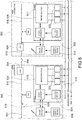
- Figure 4 shows a Multiple Unit Brake System architecture for a train consist according to the present invention, including:
- Electrical commands from the brake control handle device 401 can reach the ECPBS 411 through said communication layer: the train operator can control the brake pipe pressure from the brake handle 401 of the lead locomotive, by controlling the ECPBS 411, should the ECPBS 410 in the lead locomotive irreparably fail.
- the brake handle 401 available on the lead locomotive 402 physically forwards brake commands to the ECPBS 410 of the lead locomotive and the locomotive brake interface 404, through the communication link 415 (which is, for example, a LON network, or a CAN network, or an encoded digital signal network or an analog signal network).
- the communication link 415 which is, for example, a LON network, or a CAN network, or an encoded digital signal network or an analog signal network).
- the enable/disable device 406 (such as a switch) is used to enable or disable the brake handle 401 to selectively allow or prevent it from delivering brake commands on the communication link 415.
- the locomotive brake interface 404 is a device in charge of transferring the brake commands from the lead locomotive 402 to the trail locomotive 403 through the locomotive interconnection cable 408.
- the locomotive brake interface 409 receives brake commands through the locomotive interconnection cable 408 and transfers such brake commands to the communication link 416.
- the communication link 416 transfers the brake commands to the ECPBS 411.
- a brake control handle device 412 is connected to the communication link 416.
- An enable/disable device 413 such as a switch, is used to enable or disable the brake handle 412 in the trail locomotive 403, to selectively allow or prevent it from delivering brake commands to the communication link 416.
- an active/cut-out device 431 is used to enable or disable the ECPBS 410 to react to the brake commands issued over the communication link 415.
- an active/cut-out device 432 is used to enable or disable the ECPBS 411 to react to brake commands received through the communication link 416.
- one or more pneumatic devices 433 are used to connect or isolate the brake manifold 434 from one or more brake pneumatic pipes 418, such as, for example, a brake pipe, a brake balance pipe and an additional pneumatic pipe 13.
- one or more pneumatic devices 435 such as for example pneumatic cocks or pneumatic valves, are used to connect or isolate the brake manifold 436 from the pneumatic brake pipes 418.
- MMI Man-Machine Interface
- a similar MMI 422 is provided on board the trail locomotive 403.
- the enable/disable device 406 is set to enable the brake handle 401 to deliver brake commands over the communication link 415
- the active/cut-out device 431 is set to enable the ECPBS 410 to operate in accordance with the brake commands issued by the brake handle 401 over the communication link 415.
- the pneumatic devices 435 are set in the condition in which they couple the brake manifold 434 to the pneumatic pipes 418 allowing the ECPBS 410 to properly control the braking pressure corresponding to the commands issued from the brake handle 401.
- the enable/disable device 431 is instead set to disable the brake handle 412 in the trail locomotive, which is prevented from delivering brake commands over the communication link 416; the active/cut-out device 432 is set to disable the ECPBS 411, preventing it from operating upon brake commands received over the communication link 416.
- the pneumatic devices 435 are set in the condition in which they isolate the brake manifold 436 from the pneumatic brake pipes 418, preventing the ECPBS 411 from influencing the pressures in the pneumatic brake pipes 418.
- Man-Machine Interface 421 in the lead locomotive 402 displays functional and diagnostic information from the ECPBS 410 and diagnostic/health information received from the ECPBS 411 through communication link 416, locomotive brake interface 409, locomotive interface cable 408, locomotive brake interface 404 and communication link 415.
- the enable/disable device 406 is set to enable the brake handle 401 to deliver brake commands over the communication link 415
- the active/cut-out device 431 is set to disable the ECPBS 410 preventing it from operating upon brake commands issued by the brake handle 401 over the communication link 415
- the pneumatic devices 433 are set in the condition in which they isolate the brake manifold 434 from the brake pneumatic pipes 418, preventing the ECPBS 410 from influencing the pressures in said pneumatic pipes 418.
- the enable/disable device 413 in the trail locomotive 403 is set to disable the brake handle 412, preventing it from delivering brake commands over the communication link 416.
- the active cut-out device 432 is set to enable the ECPBS 411 to operate according to brake commands received over the communication link 416; the pneumatic devices 435 are set in the condition in which they connect the brake manifold 436 to the brake pipes 418, allowing the ECPBS 411 to control the pressures in said pipes 418 in accordance with the brake commands received from the brake handle 401 of the lead locomotive 402 through the communication link 415, the locomotive brake interface 404, the locomotive interconnection cable 408, the locomotive brake interface 409 and the communication link 416.
- Man-Machine Interface 421 in the lead locomotive 402 displace diagnostic/health information received from the ECPBS 410 and functional and diagnostic information from the ECPBS 411 through communication link 416, locomotive brake interface 415, locomotive interface cable 408, locomotive brake interface 404 and communication link 415.
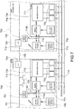
- Figure 5 shows an enhanced variant of the brake system shown in Figure 4 : the communication link between the brake handle 501 and the ECPBS 510 is made redundant by adding a communication link 520 in parallel to link 515.
- the architecture shown in Figure 5 allows the train operator to control the ECPBS 510 even if communication link 515 is in irreparable, permanent failure.
- the architecture shown in Figure 5 provides the train consist with full electro-pneumatic brake redundancy up to the level of the brake handle 501.
- the brake handle 501 available in the lead locomotive 502, physically forwards brake commands to the ECPBS 510 in the lead locomotive and to the locomotive brake interface 504 through communication link 515.
- the brake handle 501 forwards redundant brake commands to the ECPBS 510 of the lead locomotive through the additional communication link 520, which is for example a LON network, or a CAN network, or an encoded digital signal network, or an analog signal network.
- An enable/disable device 506, such as a switch, is used to enable or disable the brake handle 501, allowing or preventing it from delivering brake commands on both the communication links 515 and 520.
- the redundancy of communication links 515 and 520 allows the brake command delivery from brake handle 501 to ECPBS 510 to be single-fault tolerant.
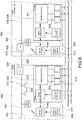
- Figure 6 shows an adaptation of the architecture of Figure 4 for the case in which a locomotive communication network is available in the locomotive consist.
- a locomotive communication network can be available to connect intelligent modules 630 (such as, for example, bus administrators, MMIs, traction control modules, event recorders, etc.) and comprises communication links 615 and 616, locomotive communication interfaces 604 and 609 and locomotive interconnection cable 608.
- intelligent modules 630 such as, for example, bus administrators, MMIs, traction control modules, event recorders, etc.
- the brake handle 601 can forward brake commands to the ECPBS 611 in the trail locomotive 603 through said locomotive communication network.
- Adaptation and synchronization of the protocol of the communication links 615 and 616 to the locomotive communication network protocol is performed by train gateways 621 and 612.
- the communication layer in Figure 6 comprises communication links 615 and 616, train gateways 621 and 622, locomotive communication interfaces 604 and 609, and locomotive interconnection cable 608.
- Figure 6 shows the lead locomotive 602 provided with a locomotive data bus 615.
- the locomotive data bus 615 is in charge of interfacing the on board intelligent modules 630.
- the locomotive data bus 615 is coupled to the locomotive data bus 616 in the trail locomotive 603, through locomotive communication interfaces 604 and 609 and inter-car bus connection 608.
- the brake handle 601 in the lead locomotive 602 physically forwards brake commands to the ECPBS 610 of the lead locomotive, and to the train gateway 621, through a communication link 615a.
- An enable/disable device 606 is used to enable or disable the brake handle 601, allowing or preventing it from delivering brake commands on the communication link 615a.
- the train gateway 621 transfers to brake commands generated by the brake handle 601 from the communication link 615a to the locomotive data bus 615 according to the related existing communication protocol. In such a way the brake commands will be issued to the train gateway 622 in the trail locomotive 603 through the locomotive communication interfaces 604 and 609, the inter-car bus connection 608 and the locomotive data bus 615, according to the prevailing communication protocol.
- the train gateway 622 transfers the brake commands from the locomotive data bus 616 to a communication link 616a.
- a brake handle 612 is connected to the communication link 616a.
- An enable/disable device 613 is used to allow or prevent the brake handle 612 to deliver brake commands on the communication link 616a.
- an active cut-out device 631 is used to enable or disable the ECPBS 610 to perform the brake commands issued over the communication link 615a.
- an active cut-out device 632 is used to enable or disable the ECPBS 611 to perform the brake commands received through the communication link 616a.
- one or more pneumatic devices such as pneumatic cocks or pneumatic valves, are used to connect or isolate the brake manifold 634 from one of more brake pneumatic pipes 618.
- one or more pneumatic devices 635 are similarly used to connect or isolate the brake manifold 636 from one or more of the brake pneumatic pipes 618.
- the enable/disable device 606 when the ECPBS 610 in the lead locomotive 602 is fully operable, exempt from failures that could prevent the train consist from properly operating, the enable/disable device 606 is set to enable the brake handle 601 to deliver brake commands over the communication link 615a, the active cut-out device is set to enable the ECPBS 610 to operate upon brake commands issued by the brake handle 601 over the communication link 615a; the pneumatic devices 633 are set in the condition in which they connect the brake manifold 634 to the brake pneumatic pipes 618 allowing the ECPBS 610 to properly control the braking pressures corresponding to brake commands issued by the brake handle 601, and the enable/disable device 613 is set to disable the brake handle 612 to prevent it from delivering brake commands over the communication link 616a; the active cut-out device 632 is set to disable the ECPBS 611, preventing it from operating upon brake commands received over the communication links 616a; the pneumatic devices 635 are set in the condition in which they isolate the brake
- the enable/disable device 606 is set to enable the brake handle 601 to deliver brake commands over the communication link 615a, and the active cut-out device 631 is set to disable the ECPBS 610 preventing it from operating according to the brake commands issued from the brake handle 601 over the communication link 615a;
- the pneumatic devices 633 are set in the condition in which they isolate the brake manifold 634 from the brake pneumatic pipes 618, preventing the ECPBS 610 from influencing the pressures in said pipes.
- the enable/disable device 612 is set to disable the brake handle 612 preventing it from delivering brake commands over the communication link 616a; the active cut-out device 632 is set to enable the ECPBS 611 to operate according to brake commands received over the communication link 616a; the pneumatic devices 635 are set in the condition in which they connect the brake manifold 636 to the brake pneumatic pipes 618, allowing the ECPBS 611 to control the pressures in the brake pneumatic pipes 618 according to the brake commands received from the brake handle 601 through the communication link 615a, the train gateway 621, the locomotive data bus 615, the locomotive communication interface 604, the inter-car connection 608, the locomotive communication interface 609, the locomotive data bus 616, the train gateway 622 and the communication link 616a.
- Figure 7 shows an enhancement of the system shown in Figure 6 : in the lead locomotive 702 the communication link between the brake handle 701 and the ECPBS 710 is made redundant by adding a communication link 715b in parallel to the communication link 715a.
- the architecture shown in Figure 7 allows the train operator to control the ECPBS 711 even in case communication link 715a is in irreparable permanent failure.
- the architecture shown in Figure 7 provides the train consist with full electro-pneumatic brake redundancy up to brake handle 701.
- the brake handle 701 in the lead locomotive 702 physically forwards brake commands to the ECPBS 710 and train gateway 721 through two independent communication links 715a and 715b.
- the redundancy of communication links 715a and 715b allows the brake command delivery from brake handle 701 to ECPBS 710 to be single-fault tolerant.
- control architecture shown in Figure 5 involves using a brake handle 501 capable of providing brake commands on independent communication links 515 and 520. Also the control architecture shown in Figure 7 involves using a brake handle 701 capable of providing brake commands on independent communication links 715a and 715b.
- Figure 8 shows a possible implementation of a brake handle suitable to furthermore improve the redundancy provided by the architectures shown in Figures 5 and 7 .
- a brake handle 501/701 includes an electromechanical arrangement 808, wherein a lever 801 is mechanically coupled through a shaft 803 with an angular position sensor or encoder 802, such as a potentiometer or an optical encoder or a magnetic encoder.
- the angular encoder 802 is connected to two independent electronic modules 804 and 805 through an electrical connection 806.
- the electronic modules 804 and 805 are predisposed to convert the electrical signals provided by the encoder 802 into proper brake commands to be issued on the communication links 515, 520 or 715a, 715b.
- Each of the electronic modules 804 and 805 can convert the signals from more than one angular encoder, for instance also the signals from an additional angular encoder 809, should the brake handle be provided with more than one operating lever, such as the additional lever indicated 810 in Figure 8 .
- Auxiliary functional switches 811 can be provided in the brake handle, connected to the electronic modules 804 and 805.
- the electronic modules 804 and 805 are coupled to respective connectors 807 and 808, which are coupled with the corresponding communication links connected to the brake handle.
- Figure 9 shows an enhancement of the brake handle device described with reference to Figure 8 .
- brake control lever 901 is coupled to two angular encoders 902, 902a through a same shaft 903.
- the encoders 902, 902a are respectively connected to independent electronic modules 905, 906, which are coupled to respective electrical connectors 907, 908.
- the brake handle is provided with more than one operating lever, for instance also with an additional lever 910, the same encoder redundancy is reproduced also for the additional lever 910, which is thus provided with angular encoders 909, 909a.
Description
- The present invention generally relates to pneumatic braking systems for railway trains, and in particular to pneumatic braking systems for locomotive consists.
- A train consist for freight transportation includes at least first and second adjacent locomotives, directly connected with each other, followed by a plurality of interconnected cars or wagons. The very first locomotive of such a consist is named the lead locomotive, whereas the at least one further locomotive of the consist is named a trail locomotive.
- In modern trains for freight transportation each locomotive of such a consist is provided with an Electronically Controlled Pneumatic Brake System (hereinafter referred to as the ECPBS) and a brake control handle device installed in the driver's cab provides electric control signals to the ECPBS in accordance with the commands by the train driver.
- The current state of the art in American freight railways operation, despite the coming introduction of the new ECP (Electronically Controlled Pneumatic) technology and the long lasting Radio Distributed Power technology (the Locotrol" system of "General Electric"), is still mostly based on train consists formed of multiple adjacent locomotives pulling a plurality of connected cars, wherein the whole train braking effort is exclusively managed by the ECPBS of the lead locomotive, controlling the pressure in the brake pipe extending through the whole train consist, according to the electric signals from the brake handle of the lead locomotive. According to the pressure variations, the pneumatic brake system of each wagon or car will individually apply a retardation effort contributing to brake, slow down and stop the whole train.
-
US 6 401 015 B discloses a train consist comprising a lead locomotive and at least one adjacent trail locomotive followed by a plurality of cars. Each of said locomotives has an electronically controlled pneumatic brake system (EPCU), which is connected to a train brake pipe that extends through the whole train consist and which is capable of controlling a braking pressure in the train brake pipe. The EPCU in lead locomotive is configured as a lead control subsystem, whereas in the trail locomotive(s) the EPCU is configured as a remote or slave control subsystem. Each of said locomotives has a brake control handle device for generating braking commands to be delivered to the respective EPCU through a communication layer for controlling the braking pressure in said brake pipe. The communication layer extends through said locomotives connecting the brake control handle device of the lead locomotive to the EPCU of the trail locomotive(s). The whole train control system is designed to provide synchronous automatic control of said at least one trail locomotive, the control of the braking pressure being made in a synchronous manner by the EPCUs of the lead and trail locomotives. - In case of a critical failure occurring in the ECPBS in the lead locomotive, the whole train can result unable to properly brake, requiring procedures and actions to rescue the train, or to replace the failing lead locomotive with an efficient one, for instance by exchanging the positions of the lead and the trail locomotives.
- An object of the present invention is to provide a train consist with an improved brake control system. This object is achieved according to the invention by a train consist having the features defined in
claim 1 and a method for operating such a train consist as defined in claim 10. - In a train consist according to the present invention, in case of a critical failure occurring to the ECPBS in the lead locomotive, signals provided by the brake handle of the lead locomotive can be extended to the ECPBS of the first adjacent trail locomotive, through a communication link extending through at least the first two adjacent locomotives of the consist, either by using spare pins on an already available AAR Multi-Unit (hereinafter MU) connector, or by using power line technology over MU pins, or by using a dedicated custom connector.
- In this way, the pneumatic brake system of the adjacent trail locomotive, still controlled through the electric signals from the brake handle in the lead locomotive, will take over control from the failing ECPBS of the lead locomotive, allowing the train to reach the end of service without major inconveniences to the operation thereof.
- Further features and advantages of the present invention will become apparent from the following description of embodiments, provided with reference to the annexed drawings, wherein:
-
Figure 1 is a diagrammatic representation of a train including a train consist formed of a lead locomotive and one trail locomotive; -
Figure 2 is a block diagram showing the structure of an ECPBS according to the prior art; -
Figure 3 shows the structure of another ECPBS according to the prior art; -
Figure 4 is a block diagram showing a structure of an ECPBS for use in a train consist according to the present invention; -
Figure 5 is a block diagram showing an enhanced variant of embodiment of the ECPBS ofFigure 4 ; -
Figure 6 shows another variant of embodiment of the ECPBS ofFigure 4 ; -
Figure 7 shows an improved variant of the ECPBS ofFigure 6 ; -
Figure 8 is a block diagram of an embodiment of a brake control handle device suited for use with the systems ofFigures 5 and7 ; and -
Figure 9 shows a variant of embodiment of the brake control handle device ofFigure 8 . -
Figure 1 shows a conventional train consist 101 formed of twoadjacent locomotives wagons 150. -
Lead locomotive 102 delivers pneumatic brake commands to traillocomotive 103 through a brake pipe and Multiple Unit commands throughMU connectors 106 and acable 105. - The
lead locomotive 102 is that from which the train operator controls the operational modes of the whole train consist 101. In particular, from thelead locomotive 102 the train operator controls the brake operational modes of the whole train consist 101. - According to the present invention, a general locomotive braking architecture and related possible implementations are disclosed, allowing the train operator to operate the train brake operational modes by using the brake handle of the lead locomotive, which is able to control either the brake system installed on the
lead locomotive 102 or the brake system installed on thetrail locomotive 103, selecting which of the two brake systems is to be activated, depending upon the "health" status of the lead locomotive brake system. -
Figure 2 shows an example of current state of the art ECPBS, comprising apneumatic manifold 201, on which one or more pneumatic components 202 (such as, for example, relay valves, check valves, triple valves or distributor valves), electro-pneumatic actuators 203 (such as, for example, solenoid valves and proportional solenoid valves), and sensors 204 (such as, for example, pressure switches and pressure transducers) are installed, and controlled by a stand-alone electronic control unit (ECU) 205 throughcables 206 wired in any of possible different fashions. - The
pneumatic manifold 201 is connected to brake cylinders, a brake pipe and an equalizing pipe, throughpiping connections 207. - The stand-alone
electronic control unit 205 receives brake commands throughelectrical cables 208 frombrake handle 209. - The signals flowing through
electrical cables 208 can be of analog type (such as, for example, currents of 4-20 mA), encoded digital type signals, Pulse-Width-Modulation type signals, Data-Communication type signals (such as, for example, CAN, or Echelon, or RS485, or Ethernet signals). - A single failure, for instance in the stand-alone
electronic control unit 205, or in theelectrical cable 208, can irreparably prevent the ECPBS from properly controlling the pressure in the brake pipe, causing the train operation to stop and requiring rescue. -
Figure 3 shows an example of current state of the art ECPBS, comprising apneumatic manifold 301, on which one or more pneumatic components 302 (such as, for example, relay valves, check valves, triple valves or distributor valves) and electro-pneumatic modules 303 controlled by integrated electronic units 304 (such as, for example, mechatronic or pneuma-tronic line replaceable units) are installed. - The
pneumatic manifold 301 is connected to brake cylinders, the brake pipe and an equalizing pipe, throughpiping connections 305. - A brake
control handle device 306 sends brake commands viaelectrical cables 307 to an electronic interface module 308 (such as, for example, a gateway, or a junction-box, or a bridge) which forwards brake commands to the integrated electronic units ofmodules 304 viaelectrical cables 309. - The signals flowing through
electrical cables 307 can be of analog type (such as, for instance, currents of 4-20 mA), encoded digital type signals, Pulse-Width-Modulation type signals, or data-communication type signals (such as, for example, CAN signals, Echelon signals, RS485 signals, Ethernet signals). - Also the signals flowing through
electrical cables 309 can be a combination of analog signals, encoded digital signals, Pulse-Width-Modulation type signals and data-communication signals. - According to various solutions, the
electronic interface module 308 can be installed on thebrake manifold 301, or can be stand-alone. - A single failure, for example in the
electronic interface module 308 or theelectrical cable 307, can irreparably prevent the ECPBS from properly controlling the pressure in the brake pipe(s), causing the train operation to stop and requiring rescue. -
Figure 4 shows a Multiple Unit Brake System architecture for a train consist according to the present invention, including: - at least two adjacent locomotives, i.e.
lead locomotive 402 andtrail locomotive 403; - lead locomotive brake apparatus, comprising a brake
control handle device 401 and a related enable/disable device 406, and an Electronically Controlled Pneumatic Brake System (ECPBS) 410; - trail locomotive brake apparatus, comprising a brake
control handle device 412 and a related enable/disable device 413, and an Electronically Controlled Pneumatic Brake System (ECPBS) 411; -
braking pipes 418; and - a communication layer, including
communication links locomotive interconnection cable 408. - Electrical commands from the brake
control handle device 401 can reach the ECPBS 411 through said communication layer: the train operator can control the brake pipe pressure from thebrake handle 401 of the lead locomotive, by controlling the ECPBS 411, should the ECPBS 410 in the lead locomotive irreparably fail. - With the architecture shown in
Figure 4 thebrake handle 401 available on thelead locomotive 402 physically forwards brake commands to the ECPBS 410 of the lead locomotive and thelocomotive brake interface 404, through the communication link 415 (which is, for example, a LON network, or a CAN network, or an encoded digital signal network or an analog signal network). - The enable/disable device 406 (such as a switch) is used to enable or disable the
brake handle 401 to selectively allow or prevent it from delivering brake commands on thecommunication link 415. - The
locomotive brake interface 404 is a device in charge of transferring the brake commands from thelead locomotive 402 to thetrail locomotive 403 through thelocomotive interconnection cable 408. - In the
trail locomotive 403 thelocomotive brake interface 409 receives brake commands through thelocomotive interconnection cable 408 and transfers such brake commands to thecommunication link 416. - The
communication link 416 transfers the brake commands to the ECPBS 411. A brakecontrol handle device 412 is connected to thecommunication link 416. An enable/disable device 413, such as a switch, is used to enable or disable thebrake handle 412 in thetrail locomotive 403, to selectively allow or prevent it from delivering brake commands to thecommunication link 416. - In the
lead locomotive 401 an active/cut-outdevice 431 is used to enable or disable the ECPBS 410 to react to the brake commands issued over thecommunication link 415. - Similarly, in the
trail locomotive 403 an active/cut-outdevice 432 is used to enable or disable the ECPBS 411 to react to brake commands received through thecommunication link 416. - In the
lead locomotive 402 one or more pneumatic devices 433 (such as, for example, pneumatic cocks or pneumatic valves) are used to connect or isolate thebrake manifold 434 from one or more brakepneumatic pipes 418, such as, for example, a brake pipe, a brake balance pipe and an additionalpneumatic pipe 13. - In the
trail locomotive 403 one or morepneumatic devices 435, such as for example pneumatic cocks or pneumatic valves, are used to connect or isolate thebrake manifold 436 from thepneumatic brake pipes 418. - A Man-Machine Interface (MMI) 421, comprising for instance a display or a screen, is connected to the
communication link 415 to show information related to theECPBSs ECPBSs similar MMI 422 is provided on board thetrail locomotive 403. - According to the present invention and with reference to the architecture shown in
Figure 4 , when theECPBS 410 in thelead locomotive 402 is fully operable and exempt from any failures that could prevent the train consist from properly operating, the enable/disabledevice 406 is set to enable the brake handle 401 to deliver brake commands over thecommunication link 415, and the active/cut-outdevice 431 is set to enable theECPBS 410 to operate in accordance with the brake commands issued by the brake handle 401 over thecommunication link 415. Thepneumatic devices 435 are set in the condition in which they couple thebrake manifold 434 to thepneumatic pipes 418 allowing theECPBS 410 to properly control the braking pressure corresponding to the commands issued from thebrake handle 401. - The enable/disable
device 431 is instead set to disable thebrake handle 412 in the trail locomotive, which is prevented from delivering brake commands over thecommunication link 416; the active/cut-outdevice 432 is set to disable theECPBS 411, preventing it from operating upon brake commands received over thecommunication link 416. Thepneumatic devices 435 are set in the condition in which they isolate thebrake manifold 436 from thepneumatic brake pipes 418, preventing theECPBS 411 from influencing the pressures in thepneumatic brake pipes 418. - Man-
Machine Interface 421 in thelead locomotive 402 displays functional and diagnostic information from theECPBS 410 and diagnostic/health information received from theECPBS 411 throughcommunication link 416,locomotive brake interface 409,locomotive interface cable 408,locomotive brake interface 404 andcommunication link 415. - With reference to the architecture shown in
Figure 4 , when theECPBS 410 in thelead locomotive 402 is affected by one or more failures preventing the train consist from properly operating, the enable/disabledevice 406 is set to enable the brake handle 401 to deliver brake commands over thecommunication link 415, and the active/cut-outdevice 431 is set to disable theECPBS 410 preventing it from operating upon brake commands issued by the brake handle 401 over thecommunication link 415; thepneumatic devices 433 are set in the condition in which they isolate thebrake manifold 434 from the brakepneumatic pipes 418, preventing theECPBS 410 from influencing the pressures in saidpneumatic pipes 418. - The enable/disable
device 413 in thetrail locomotive 403 is set to disable thebrake handle 412, preventing it from delivering brake commands over thecommunication link 416. The active cut-outdevice 432 is set to enable theECPBS 411 to operate according to brake commands received over thecommunication link 416; thepneumatic devices 435 are set in the condition in which they connect thebrake manifold 436 to thebrake pipes 418, allowing theECPBS 411 to control the pressures in saidpipes 418 in accordance with the brake commands received from the brake handle 401 of thelead locomotive 402 through thecommunication link 415, thelocomotive brake interface 404, thelocomotive interconnection cable 408, thelocomotive brake interface 409 and thecommunication link 416. - Man-
Machine Interface 421 in thelead locomotive 402 displace diagnostic/health information received from theECPBS 410 and functional and diagnostic information from theECPBS 411 throughcommunication link 416,locomotive brake interface 415,locomotive interface cable 408,locomotive brake interface 404 andcommunication link 415. -
Figure 5 shows an enhanced variant of the brake system shown inFigure 4 : the communication link between thebrake handle 501 and theECPBS 510 is made redundant by adding acommunication link 520 in parallel to link 515. - Compared with
Figure 4 , when a failure on thecommunication link 415 would prevent the train operator from controlling both theECPBSs Figure 5 allows the train operator to control theECPBS 510 even if communication link 515 is in irreparable, permanent failure. In summary, the architecture shown inFigure 5 provides the train consist with full electro-pneumatic brake redundancy up to the level of thebrake handle 501. - In the variant shown in
Figure 5 thebrake handle 501, available in thelead locomotive 502, physically forwards brake commands to theECPBS 510 in the lead locomotive and to thelocomotive brake interface 504 throughcommunication link 515. In addition, the brake handle 501 forwards redundant brake commands to theECPBS 510 of the lead locomotive through theadditional communication link 520, which is for example a LON network, or a CAN network, or an encoded digital signal network, or an analog signal network. An enable/disabledevice 506, such as a switch, is used to enable or disable thebrake handle 501, allowing or preventing it from delivering brake commands on both thecommunication links communication links -
Figure 6 shows an adaptation of the architecture ofFigure 4 for the case in which a locomotive communication network is available in the locomotive consist. Such a locomotive communication network can be available to connect intelligent modules 630 (such as, for example, bus administrators, MMIs, traction control modules, event recorders, etc.) and comprisescommunication links locomotive interconnection cable 608. - The brake handle 601 can forward brake commands to the
ECPBS 611 in thetrail locomotive 603 through said locomotive communication network. Adaptation and synchronization of the protocol of thecommunication links train gateways - The communication layer in
Figure 6 comprisescommunication links train gateways locomotive interconnection cable 608. - According to the architecture shown in
Figure 6 , like inFigure 4 the train operator can control the braking pipe pressures from thebrake handle 601 in the lead locomotive, by controlling theECPBS 611, should theECPBS 610 in the lead locomotive irreparably fail.Figure 6 shows thelead locomotive 602 provided with alocomotive data bus 615. Thelocomotive data bus 615 is in charge of interfacing the on boardintelligent modules 630. - The
locomotive data bus 615 is coupled to thelocomotive data bus 616 in thetrail locomotive 603, through locomotive communication interfaces 604 and 609 andinter-car bus connection 608. - According to the present invention, in the architecture shown in
Figure 6 thebrake handle 601 in thelead locomotive 602 physically forwards brake commands to theECPBS 610 of the lead locomotive, and to thetrain gateway 621, through acommunication link 615a. - An enable/disable
device 606 is used to enable or disable thebrake handle 601, allowing or preventing it from delivering brake commands on thecommunication link 615a. - The
train gateway 621 transfers to brake commands generated by the brake handle 601 from thecommunication link 615a to thelocomotive data bus 615 according to the related existing communication protocol. In such a way the brake commands will be issued to thetrain gateway 622 in thetrail locomotive 603 through the locomotive communication interfaces 604 and 609, theinter-car bus connection 608 and thelocomotive data bus 615, according to the prevailing communication protocol. - The
train gateway 622 transfers the brake commands from thelocomotive data bus 616 to acommunication link 616a. - In the trail locomotive 603 a
brake handle 612 is connected to thecommunication link 616a. An enable/disabledevice 613 is used to allow or prevent the brake handle 612 to deliver brake commands on thecommunication link 616a. - In the lead locomotive 602 an active cut-out
device 631 is used to enable or disable theECPBS 610 to perform the brake commands issued over thecommunication link 615a. - Similarly, in the
trail locomotive 603 an active cut-outdevice 632 is used to enable or disable theECPBS 611 to perform the brake commands received through thecommunication link 616a. - In the
lead locomotive 603 one or more pneumatic devices, such as pneumatic cocks or pneumatic valves, are used to connect or isolate thebrake manifold 634 from one of more brakepneumatic pipes 618. - In the
trail locomotive 603 one or morepneumatic devices 635 are similarly used to connect or isolate thebrake manifold 636 from one or more of the brakepneumatic pipes 618. - Still with reference to
Figure 6 , when theECPBS 610 in thelead locomotive 602 is fully operable, exempt from failures that could prevent the train consist from properly operating, the enable/disabledevice 606 is set to enable the brake handle 601 to deliver brake commands over thecommunication link 615a, the active cut-out device is set to enable theECPBS 610 to operate upon brake commands issued by the brake handle 601 over thecommunication link 615a; thepneumatic devices 633 are set in the condition in which they connect thebrake manifold 634 to the brakepneumatic pipes 618 allowing theECPBS 610 to properly control the braking pressures corresponding to brake commands issued by thebrake handle 601, and the enable/disabledevice 613 is set to disable the brake handle 612 to prevent it from delivering brake commands over thecommunication link 616a; the active cut-outdevice 632 is set to disable theECPBS 611, preventing it from operating upon brake commands received over thecommunication links 616a; thepneumatic devices 635 are set in the condition in which they isolate thebrake manifold 636 from the brakepneumatic pipes 618, preventing theECPBS 611 from influencing the pressures in saidpipes 618. - According to the present invention, and as shown in
Figure 6 , when theECPBS 610 in thelead locomotive 602 is affected by one or more failures which prevent the train consist from properly operating, the enable/disabledevice 606 is set to enable the brake handle 601 to deliver brake commands over thecommunication link 615a, and the active cut-outdevice 631 is set to disable theECPBS 610 preventing it from operating according to the brake commands issued from the brake handle 601 over thecommunication link 615a; thepneumatic devices 633 are set in the condition in which they isolate thebrake manifold 634 from the brakepneumatic pipes 618, preventing theECPBS 610 from influencing the pressures in said pipes. In thetrail locomotive 603 the enable/disabledevice 612 is set to disable the brake handle 612 preventing it from delivering brake commands over thecommunication link 616a; the active cut-outdevice 632 is set to enable theECPBS 611 to operate according to brake commands received over thecommunication link 616a; thepneumatic devices 635 are set in the condition in which they connect thebrake manifold 636 to the brakepneumatic pipes 618, allowing theECPBS 611 to control the pressures in the brakepneumatic pipes 618 according to the brake commands received from the brake handle 601 through thecommunication link 615a, thetrain gateway 621, thelocomotive data bus 615, thelocomotive communication interface 604, theinter-car connection 608, thelocomotive communication interface 609, thelocomotive data bus 616, thetrain gateway 622 and thecommunication link 616a. -
Figure 7 shows an enhancement of the system shown inFigure 6 : in thelead locomotive 702 the communication link between thebrake handle 701 and theECPBS 710 is made redundant by adding acommunication link 715b in parallel to thecommunication link 715a. Compared withFigure 6 , when a failure in thecommunication link 615a would prevent the train operator from controlling both theECPBSs Figure 7 allows the train operator to control theECPBS 711 even incase communication link 715a is in irreparable permanent failure. In summary, the architecture shown inFigure 7 provides the train consist with full electro-pneumatic brake redundancy up to brake handle 701. - According to the invention, in the variant shown in
Figure 7 thebrake handle 701 in thelead locomotive 702 physically forwards brake commands to theECPBS 710 andtrain gateway 721 through twoindependent communication links communication links - The control architecture shown in
Figure 5 involves using abrake handle 501 capable of providing brake commands onindependent communication links Figure 7 involves using abrake handle 701 capable of providing brake commands onindependent communication links -
Figure 8 shows a possible implementation of a brake handle suitable to furthermore improve the redundancy provided by the architectures shown inFigures 5 and7 . - According to
Figure 8 abrake handle 501/701 includes anelectromechanical arrangement 808, wherein alever 801 is mechanically coupled through ashaft 803 with an angular position sensor orencoder 802, such as a potentiometer or an optical encoder or a magnetic encoder. Theangular encoder 802 is connected to two independentelectronic modules electrical connection 806. - The
electronic modules encoder 802 into proper brake commands to be issued on the communication links 515, 520 or 715a, 715b. - Each of the
electronic modules Figure 8 . - Auxiliary
functional switches 811 can be provided in the brake handle, connected to theelectronic modules - The
electronic modules respective connectors -
Figure 9 shows an enhancement of the brake handle device described with reference toFigure 8 . - In the variant of
Figure 9 brake control lever 901 is coupled to twoangular encoders same shaft 903. Theencoders electronic modules electrical connectors - If the brake handle is provided with more than one operating lever, for instance also with an
additional lever 910, the same encoder redundancy is reproduced also for theadditional lever 910, which is thus provided withangular encoders - The variant of
Figure 9 provides complete electronic redundancy, so that the resulting brake handle is single-fault redundant.
Claims (11)
- A train consist (101) comprising a lead locomotive (402; 502; 602; ...) and at least one adjacent trail locomotive (403; 503; 603; ...), followed by a plurality of cars (150), wherein:each of said locomotives (402, 403; 502, 503; ...) has an electronically controlled pneumatic brake system ECPBS (410, 411; 510, 511; ...) connected to a train brake pipe (418; 518; ...) that extends through the whole train consist, said ECPBS (410, 411; 510, 511; ...) being capable of controlling a braking pressure in said train brake pipe (418; 518; ...);each of said locomotives (402, 403; 502, 503; ...) has a brake control handle device (401, 412; 501; 512; ...) for generating braking commands to be delivered to the respective ECPBS (410, 411; 510, 511; ...) through a communication layer (415, 416; 515, 516; ...), said braking commands being suitable to control, by means of said ECPBS, the braking pressure in said brake pipe (418; 518; ...);said communication layer (415, 416; 515, 516; ...) extending through the lead locomotive (402; 502; ...) and said at least one trail locomotive (403; 503; ...) of the consist, connecting the brake control handle device (401; 501; ...) of the lead locomotive (402; 502; ...) to the ECPBS of said at least one trail locomotive (403; 503; ...), said communication layer (415, 416; 515, 516; ...) being arranged to forward, in case of failure of the ECPBS of the lead locomotive, said braking commands from the brake control handle device (401; 501; ...) of the lead locomotive (402; 502; ...) to the ECPBS of the trail locomotive (403; 503; ...), allowing to control the braking pressure in said brake pipe (418; 518; ...) by means of the ECPBS of said at least one trail locomotive (403;503; ...) in accordance with the brake commands generated by the brake control handle device (401; 501; ...) of the lead locomotive (402; 502; ...).
- A train consist according to claim 1, wherein
said at least one trail locomotive (403; 503; ...) has means (413; 513; ...) for enabling and disabling the corresponding brake control handle device (412; 512; ...), to allow and prevent said brake control handle device (412; 512; ...) from issuing brake commands over said communication layer (416; 516; ...). - A train consist according to claim 1 or claim 2, wherein
said communication layer includes independent communication links (415, 416; 515, 516; ...) connecting in said locomotives (402, 403; 502, 503; ...) the respective brake control handle device (401, 412; 501, 512; ...) with the corresponding ECPBS (410, 411; 510, 511; ...). - A train consist according to claim 3, wherein each brake control handle device comprises
first and second independent electronic modules (804, 805; 905, 906) connected to angular position encoder means (802, 809; 902, 909) coupled to at least one brake control lever (801, 810; 901, 910), said electronic modules (804, 805; 905, 906) being connected to said independent communication links (515; 715) and predisposed for converting angular position signals into brake commands. - A train consist according to claim 4, wherein:each brake control handle device includes at least one brake control lever (801, 810; 901, 910), for generating braking commands to be delivered to the respective ECPBS (510, 511; 710, 711) through the communication layer (515, 516; 715, 716);said first and second independent electronic modules (804, 805; 905, 906) being associated with each brake control lever (801, 810; 901, 910).
- A train consist according to any of the preceding claims, wherein
said communication layer (615, 616; 715, 716) connects the brake control handle device (601, 612; 701, 712) of the lead locomotive (602; 702) to the ECPBS (611; 711) of said at least one trail locomotive (603; 703) through gateway means (621; 721) capable of converting a first protocol for local communication between an ECPBS (610; 710) and the corresponding brake control handle device (601, 612; 701, 712) into a second protocol for inter-locomotive communication. - A train consist according to any of claims 3 to 6, wherein
each of said locomotives (402, 403; 502, 503; ...) has means (406, 413; 506, 513; ...) for enabling and disabling the respective brake control handle device (401, 412; 501, 512; ...) to allow and prevent said brake control lever device from issuing brake commands over said communication layer (415, 416; 515, 516; ...). - A train consist according to any of the preceding claims, wherein
the lead locomotive (402) has a man-machine interface (421) connected to said communication layer (415, 416), arranged to display operating values, including the brake pipe pressure, provided by the ECPBS (411) of said trail locomotive (403). - A train consist according to any of the preceding claims, wherein
said communication layer extends at least through the two first adjacent locomotives (402, 403; 502, 503; ...), through pins in multi-unit connectors (807, 808; 907, 908). - Method for operating a train consist according to claim 7, comprising a normal operation mode including:enabling the brake control handle device (401; 501; ...) of the lead locomotive (402; 502; ...) to issue braking commands over the communication layer (415; 515; ...);disabling the brake control handle device (412; 512; ...) of said at least one trail locomotive (403; 503; ...) preventing it from issuing braking commands over the communication layer (416; 516; ...);enabling the ECPBS (410; 510; ...) of the lead locomotive (402; 502; ...) to control the braking pressure in the brake pipe (418; 518; ...) in accordance with the braking commands received from the brake control handle device (401; 501, ...) of the lead locomotive (402; 502; ...) anddisabling the ECPBS (412; 512; ...) of said at least one trail locomotive (403; 503; ...) preventing it from controlling and influencing the pressure in the brake pipe (418; 518; ...).
- A method according to claim 10, comprising a failure operation mode for operating said train consist when the ECPBS (410; 510; ...) of the lead locomotive (402; 502; ...) is affected by a failure preventing said ECPBS to control the pressure in the brake pipe (418; 518; ...) in accordance with the brake commands generated by the control handle (401; 501; ...) device of the lead locomotive (402; 502; ...), including:enabling the brake control handle device (401; 501; ...) of the lead locomotive (402; 502; ...) to issue braking commands over the communication layer (415, 416; 515, 516; ...);disabling the brake control handle device (412; 512; ...) of the at least one trail locomotive (403; 503; ...) to issue braking commands over the communication layer (415, 416; 515, 516; ...);disabling the ECPBS (410; 510; ...) of the lead locomotive (402; 502; ...) preventing it from controlling the pressure in the brake pipe (418; 518; ...); andenabling the ECPBS (411; 511; ...) of a trail locomotive (403; 503; ...) to control the pressure in the brake pipe (418; 518; ...) according to the braking commands received from the brake control handle device (401; 501; ...) of the lead locomotive (402; 502; ...) through the communication layer (415,416; 515, 516; ...).
Priority Applications (1)
| Application Number | Priority Date | Filing Date | Title |
|---|---|---|---|
| PL14777065.5T PL3049304T5 (en) | 2013-09-26 | 2014-09-25 | Pneumatic brake system redundancy in locomotive consists |
Applications Claiming Priority (2)
| Application Number | Priority Date | Filing Date | Title |
|---|---|---|---|
| US14/038,177 US9868454B2 (en) | 2013-09-26 | 2013-09-26 | Pneumatic brake system redundancy in locomotive consists |
| PCT/EP2014/070579 WO2015044319A1 (en) | 2013-09-26 | 2014-09-25 | Pneumatic brake system redundancy in locomotive consists |
Publications (3)
| Publication Number | Publication Date |
|---|---|
| EP3049304A1 EP3049304A1 (en) | 2016-08-03 |
| EP3049304B1 true EP3049304B1 (en) | 2020-06-03 |
| EP3049304B2 EP3049304B2 (en) | 2023-08-16 |
Family
ID=51627290
Family Applications (1)
| Application Number | Title | Priority Date | Filing Date |
|---|---|---|---|
| EP14777065.5A Active EP3049304B2 (en) | 2013-09-26 | 2014-09-25 | Pneumatic brake system redundancy in locomotive consists |
Country Status (9)
| Country | Link |
|---|---|
| US (1) | US9868454B2 (en) |
| EP (1) | EP3049304B2 (en) |
| CN (1) | CN105658497A (en) |
| AU (1) | AU2014326923B2 (en) |
| CA (1) | CA2922508C (en) |
| PL (1) | PL3049304T5 (en) |
| RU (1) | RU2016107588A (en) |
| WO (1) | WO2015044319A1 (en) |
| ZA (1) | ZA201602566B (en) |
Families Citing this family (6)
| Publication number | Priority date | Publication date | Assignee | Title |
|---|---|---|---|---|
| WO2016075642A1 (en) * | 2014-11-13 | 2016-05-19 | Faiveley Transport Italia S.P.A. | Electro-pneumatic assembly, particularly for a pneumatic braking installation of railway vehicles |
| US20170305449A1 (en) * | 2016-04-22 | 2017-10-26 | Westinghouse Air Brake Technologies Corporation | Train Brake Control System And Method |
| CN109204341B (en) * | 2018-09-13 | 2020-06-23 | 中车株洲电力机车有限公司 | Master-slave control system and method and storage battery engineering truck brake reconnection system |
| WO2020060552A1 (en) * | 2018-09-20 | 2020-03-26 | New York Air Brake Llc | Brake redundancy in a locomotive consist |
| FR3100785B1 (en) * | 2019-09-17 | 2021-09-24 | Speedinnov | Emergency interface system between two separate railway vehicles, railway vehicle and associated method |
| US11708056B2 (en) | 2019-12-03 | 2023-07-25 | Crrc Nanjing Puzhen Co., Ltd. | Emergency braking control circuit based on coupler coupling detection |
Citations (10)
| Publication number | Priority date | Publication date | Assignee | Title |
|---|---|---|---|---|
| US4582280A (en) | 1983-09-14 | 1986-04-15 | Harris Corporation | Railroad communication system |
| US5907676A (en) | 1996-10-04 | 1999-05-25 | Hitachi, Ltd. | Information processing system, communication method, and recording medium |
| US6401015B1 (en) | 1997-10-14 | 2002-06-04 | Scot Stewart | Distributed power and electronic air brake control system for a train and associated methods |
| US20070063581A1 (en) | 2005-09-16 | 2007-03-22 | New York Air Brake Corporation | Electronic brake controller with selectable display |
| US20100241295A1 (en) | 2009-03-17 | 2010-09-23 | Jared Klineman Cooper | System and method for communicating data in locomotive consist or other vehicle consist |
| WO2011050125A1 (en) | 2009-10-22 | 2011-04-28 | General Electric Company | System and method for communicating data in a vehicle consist |
| WO2012037208A1 (en) | 2010-09-14 | 2012-03-22 | General Electric Company | System and method for communicating data in a vehicle consist |
| US20120165379A1 (en) | 1999-07-23 | 2012-06-28 | Alwyn Company Inc. | Allantoin-containing skin cream |
| US20130018560A1 (en) | 2011-07-14 | 2013-01-17 | Smith Eugene A | Method and system for rail vehicle control |
| EP2705994A1 (en) | 2012-09-11 | 2014-03-12 | Bombardier Transportation GmbH | Control arrangement for a rail vehicle |
Family Cites Families (6)
| Publication number | Priority date | Publication date | Assignee | Title |
|---|---|---|---|---|
| CA2140401C (en) | 1994-11-16 | 1999-01-12 | Ralph Santoro Jr. | Apparatus for determining the absolute position of throttle dynamic brake and reverser handles on a locomotive control stand |
| US7703860B2 (en) * | 2006-09-14 | 2010-04-27 | New York Air Brake Corporation | Remote control brake system and manifold |
| US8190313B2 (en) * | 2008-10-10 | 2012-05-29 | General Electric Company | System and method for reducing a penalty period for a distributed power train |
| US8346414B2 (en) * | 2009-03-16 | 2013-01-01 | Ztr Control Systems | System and method for determining whether a locomotive in a consist is in leading mode or trailing mode |
| US8682513B2 (en) | 2011-04-14 | 2014-03-25 | General Electric Company | Communication management system and method for a rail vehicle |
| US8924117B2 (en) * | 2012-05-04 | 2014-12-30 | Wabtec Holding Corp. | Brake monitoring system for an air brake arrangement |
-
2013
- 2013-09-26 US US14/038,177 patent/US9868454B2/en active Active
-
2014
- 2014-09-25 WO PCT/EP2014/070579 patent/WO2015044319A1/en active Application Filing
- 2014-09-25 CA CA2922508A patent/CA2922508C/en active Active
- 2014-09-25 EP EP14777065.5A patent/EP3049304B2/en active Active
- 2014-09-25 RU RU2016107588A patent/RU2016107588A/en not_active Application Discontinuation
- 2014-09-25 CN CN201480053286.8A patent/CN105658497A/en active Pending
- 2014-09-25 AU AU2014326923A patent/AU2014326923B2/en active Active
- 2014-09-25 PL PL14777065.5T patent/PL3049304T5/en unknown
-
2016
- 2016-04-13 ZA ZA2016/02566A patent/ZA201602566B/en unknown
Patent Citations (10)
| Publication number | Priority date | Publication date | Assignee | Title |
|---|---|---|---|---|
| US4582280A (en) | 1983-09-14 | 1986-04-15 | Harris Corporation | Railroad communication system |
| US5907676A (en) | 1996-10-04 | 1999-05-25 | Hitachi, Ltd. | Information processing system, communication method, and recording medium |
| US6401015B1 (en) | 1997-10-14 | 2002-06-04 | Scot Stewart | Distributed power and electronic air brake control system for a train and associated methods |
| US20120165379A1 (en) | 1999-07-23 | 2012-06-28 | Alwyn Company Inc. | Allantoin-containing skin cream |
| US20070063581A1 (en) | 2005-09-16 | 2007-03-22 | New York Air Brake Corporation | Electronic brake controller with selectable display |
| US20100241295A1 (en) | 2009-03-17 | 2010-09-23 | Jared Klineman Cooper | System and method for communicating data in locomotive consist or other vehicle consist |
| WO2011050125A1 (en) | 2009-10-22 | 2011-04-28 | General Electric Company | System and method for communicating data in a vehicle consist |
| WO2012037208A1 (en) | 2010-09-14 | 2012-03-22 | General Electric Company | System and method for communicating data in a vehicle consist |
| US20130018560A1 (en) | 2011-07-14 | 2013-01-17 | Smith Eugene A | Method and system for rail vehicle control |
| EP2705994A1 (en) | 2012-09-11 | 2014-03-12 | Bombardier Transportation GmbH | Control arrangement for a rail vehicle |
Non-Patent Citations (2)
| Title |
|---|
| ANONYMOUS: "Department of Transportation Federal Railroad Administration 49 CFR Part 232 Electronically Controlled Pneumatic Brake Systems; Final Rule", FEDERAL REGISTER, vol. 73, no. 201, 16 October 2008 (2008-10-16), pages 61512 - 61557, XP055976566 |
| ANONYMOUS: "description of the compressed air brake system ", OERLIKON-KNORR, 1 April 2003 (2003-04-01), XP055976568 |
Also Published As
| Publication number | Publication date |
|---|---|
| CA2922508A1 (en) | 2015-04-02 |
| CA2922508C (en) | 2023-11-07 |
| RU2016107588A3 (en) | 2018-05-29 |
| EP3049304B2 (en) | 2023-08-16 |
| EP3049304A1 (en) | 2016-08-03 |
| WO2015044319A1 (en) | 2015-04-02 |
| US9868454B2 (en) | 2018-01-16 |
| ZA201602566B (en) | 2022-05-25 |
| AU2014326923B2 (en) | 2018-06-28 |
| PL3049304T5 (en) | 2023-12-04 |
| CN105658497A (en) | 2016-06-08 |
| RU2016107588A (en) | 2017-10-30 |
| PL3049304T3 (en) | 2020-11-16 |
| US20150083529A1 (en) | 2015-03-26 |
| AU2014326923A1 (en) | 2016-03-17 |
Similar Documents
| Publication | Publication Date | Title |
|---|---|---|
| EP3049304B1 (en) | Pneumatic brake system redundancy in locomotive consists | |
| CA2660043C (en) | Interface system for wire distributed power | |
| EP1531109B1 (en) | Electronic braking control for a locomotive | |
| JP2019524555A (en) | Electronic control method of braking equipment in automatically controllable commercial vehicle towing configuration and braking equipment controllable by electronic control in automatically controllable commercial vehicle towing configuration | |
| CN112739591B (en) | Brake system for a vehicle, vehicle and method of controlling a brake system of a vehicle | |
| EP2705994B1 (en) | Control arrangement for a rail vehicle | |
| US10046778B2 (en) | Vehicle communication system | |
| EP3626557B1 (en) | Brake system for a vehicle | |
| US20220258712A1 (en) | Parking Brake Device for a Utility Vehicle | |
| WO2002022425A1 (en) | Integrated train control | |
| CN112061104A (en) | Brake control system | |
| US20220340111A1 (en) | Trailer Braking System | |
| CN112703138B (en) | Brake system for vehicle | |
| CA2720540C (en) | Ecp terminal mode operation | |
| US20200307534A1 (en) | Wheel speed sensor system, vehicle including said wheel speed sensor system and method of processing wheel speed signals | |
| EP0976633B1 (en) | A control and communication system for railway trains | |
| US6997520B1 (en) | Control and communication system for railway trains | |
| EP1053148B1 (en) | Integrated train electrical and pneumatic brakes | |
| EP1291259B1 (en) | Electropneumatic brake system for trains |
Legal Events
| Date | Code | Title | Description |
|---|---|---|---|
| PUAI | Public reference made under article 153(3) epc to a published international application that has entered the european phase |
Free format text: ORIGINAL CODE: 0009012 |
|
| 17P | Request for examination filed |
Effective date: 20160219 |
|
| AK | Designated contracting states |
Kind code of ref document: A1 Designated state(s): AL AT BE BG CH CY CZ DE DK EE ES FI FR GB GR HR HU IE IS IT LI LT LU LV MC MK MT NL NO PL PT RO RS SE SI SK SM TR |
|
| AX | Request for extension of the european patent |
Extension state: BA ME |
|
| DAX | Request for extension of the european patent (deleted) | ||
| GRAP | Despatch of communication of intention to grant a patent |
Free format text: ORIGINAL CODE: EPIDOSNIGR1 |
|
| STAA | Information on the status of an ep patent application or granted ep patent |
Free format text: STATUS: GRANT OF PATENT IS INTENDED |
|
| INTG | Intention to grant announced |
Effective date: 20191213 |
|
| GRAS | Grant fee paid |
Free format text: ORIGINAL CODE: EPIDOSNIGR3 |
|
| GRAA | (expected) grant |
Free format text: ORIGINAL CODE: 0009210 |
|
| STAA | Information on the status of an ep patent application or granted ep patent |
Free format text: STATUS: THE PATENT HAS BEEN GRANTED |
|
| AK | Designated contracting states |
Kind code of ref document: B1 Designated state(s): AL AT BE BG CH CY CZ DE DK EE ES FI FR GB GR HR HU IE IS IT LI LT LU LV MC MK MT NL NO PL PT RO RS SE SI SK SM TR |
|
| REG | Reference to a national code |
Ref country code: GB Ref legal event code: FG4D |
|
| REG | Reference to a national code |
Ref country code: CH Ref legal event code: EP Ref country code: AT Ref legal event code: REF Ref document number: 1276718 Country of ref document: AT Kind code of ref document: T Effective date: 20200615 |
|
| REG | Reference to a national code |
Ref country code: DE Ref legal event code: R096 Ref document number: 602014066233 Country of ref document: DE |
|
| REG | Reference to a national code |
Ref country code: CH Ref legal event code: NV Representative=s name: VALIPAT S.A. C/O BOVARD SA NEUCHATEL, CH |
|
| REG | Reference to a national code |
Ref country code: LT Ref legal event code: MG4D |
|
| PG25 | Lapsed in a contracting state [announced via postgrant information from national office to epo] |
Ref country code: FI Free format text: LAPSE BECAUSE OF FAILURE TO SUBMIT A TRANSLATION OF THE DESCRIPTION OR TO PAY THE FEE WITHIN THE PRESCRIBED TIME-LIMIT Effective date: 20200603 Ref country code: GR Free format text: LAPSE BECAUSE OF FAILURE TO SUBMIT A TRANSLATION OF THE DESCRIPTION OR TO PAY THE FEE WITHIN THE PRESCRIBED TIME-LIMIT Effective date: 20200904 Ref country code: NO Free format text: LAPSE BECAUSE OF FAILURE TO SUBMIT A TRANSLATION OF THE DESCRIPTION OR TO PAY THE FEE WITHIN THE PRESCRIBED TIME-LIMIT Effective date: 20200903 Ref country code: SE Free format text: LAPSE BECAUSE OF FAILURE TO SUBMIT A TRANSLATION OF THE DESCRIPTION OR TO PAY THE FEE WITHIN THE PRESCRIBED TIME-LIMIT Effective date: 20200603 Ref country code: LT Free format text: LAPSE BECAUSE OF FAILURE TO SUBMIT A TRANSLATION OF THE DESCRIPTION OR TO PAY THE FEE WITHIN THE PRESCRIBED TIME-LIMIT Effective date: 20200603 |
|
| REG | Reference to a national code |
Ref country code: NL Ref legal event code: MP Effective date: 20200603 |
|
| PG25 | Lapsed in a contracting state [announced via postgrant information from national office to epo] |
Ref country code: BG Free format text: LAPSE BECAUSE OF FAILURE TO SUBMIT A TRANSLATION OF THE DESCRIPTION OR TO PAY THE FEE WITHIN THE PRESCRIBED TIME-LIMIT Effective date: 20200903 Ref country code: HR Free format text: LAPSE BECAUSE OF FAILURE TO SUBMIT A TRANSLATION OF THE DESCRIPTION OR TO PAY THE FEE WITHIN THE PRESCRIBED TIME-LIMIT Effective date: 20200603 Ref country code: LV Free format text: LAPSE BECAUSE OF FAILURE TO SUBMIT A TRANSLATION OF THE DESCRIPTION OR TO PAY THE FEE WITHIN THE PRESCRIBED TIME-LIMIT Effective date: 20200603 Ref country code: RS Free format text: LAPSE BECAUSE OF FAILURE TO SUBMIT A TRANSLATION OF THE DESCRIPTION OR TO PAY THE FEE WITHIN THE PRESCRIBED TIME-LIMIT Effective date: 20200603 |
|
| REG | Reference to a national code |
Ref country code: AT Ref legal event code: MK05 Ref document number: 1276718 Country of ref document: AT Kind code of ref document: T Effective date: 20200603 |
|
| PG25 | Lapsed in a contracting state [announced via postgrant information from national office to epo] |
Ref country code: NL Free format text: LAPSE BECAUSE OF FAILURE TO SUBMIT A TRANSLATION OF THE DESCRIPTION OR TO PAY THE FEE WITHIN THE PRESCRIBED TIME-LIMIT Effective date: 20200603 Ref country code: AL Free format text: LAPSE BECAUSE OF FAILURE TO SUBMIT A TRANSLATION OF THE DESCRIPTION OR TO PAY THE FEE WITHIN THE PRESCRIBED TIME-LIMIT Effective date: 20200603 |
|
| PG25 | Lapsed in a contracting state [announced via postgrant information from national office to epo] |
Ref country code: AT Free format text: LAPSE BECAUSE OF FAILURE TO SUBMIT A TRANSLATION OF THE DESCRIPTION OR TO PAY THE FEE WITHIN THE PRESCRIBED TIME-LIMIT Effective date: 20200603 Ref country code: RO Free format text: LAPSE BECAUSE OF FAILURE TO SUBMIT A TRANSLATION OF THE DESCRIPTION OR TO PAY THE FEE WITHIN THE PRESCRIBED TIME-LIMIT Effective date: 20200603 Ref country code: PT Free format text: LAPSE BECAUSE OF FAILURE TO SUBMIT A TRANSLATION OF THE DESCRIPTION OR TO PAY THE FEE WITHIN THE PRESCRIBED TIME-LIMIT Effective date: 20201006 Ref country code: SM Free format text: LAPSE BECAUSE OF FAILURE TO SUBMIT A TRANSLATION OF THE DESCRIPTION OR TO PAY THE FEE WITHIN THE PRESCRIBED TIME-LIMIT Effective date: 20200603 Ref country code: EE Free format text: LAPSE BECAUSE OF FAILURE TO SUBMIT A TRANSLATION OF THE DESCRIPTION OR TO PAY THE FEE WITHIN THE PRESCRIBED TIME-LIMIT Effective date: 20200603 Ref country code: ES Free format text: LAPSE BECAUSE OF FAILURE TO SUBMIT A TRANSLATION OF THE DESCRIPTION OR TO PAY THE FEE WITHIN THE PRESCRIBED TIME-LIMIT Effective date: 20200603 Ref country code: CZ Free format text: LAPSE BECAUSE OF FAILURE TO SUBMIT A TRANSLATION OF THE DESCRIPTION OR TO PAY THE FEE WITHIN THE PRESCRIBED TIME-LIMIT Effective date: 20200603 |
|
| PG25 | Lapsed in a contracting state [announced via postgrant information from national office to epo] |
Ref country code: SK Free format text: LAPSE BECAUSE OF FAILURE TO SUBMIT A TRANSLATION OF THE DESCRIPTION OR TO PAY THE FEE WITHIN THE PRESCRIBED TIME-LIMIT Effective date: 20200603 Ref country code: IS Free format text: LAPSE BECAUSE OF FAILURE TO SUBMIT A TRANSLATION OF THE DESCRIPTION OR TO PAY THE FEE WITHIN THE PRESCRIBED TIME-LIMIT Effective date: 20201003 |
|
| REG | Reference to a national code |
Ref country code: DE Ref legal event code: R026 Ref document number: 602014066233 Country of ref document: DE |
|
| PLBI | Opposition filed |
Free format text: ORIGINAL CODE: 0009260 |
|
| PLAX | Notice of opposition and request to file observation + time limit sent |
Free format text: ORIGINAL CODE: EPIDOSNOBS2 |
|
| 26 | Opposition filed |
Opponent name: KNORR-BREMSE SYSTEME FUER SCHIENENFAHRZEUGE GMBH Effective date: 20210303 |
|
| PG25 | Lapsed in a contracting state [announced via postgrant information from national office to epo] |
Ref country code: DK Free format text: LAPSE BECAUSE OF FAILURE TO SUBMIT A TRANSLATION OF THE DESCRIPTION OR TO PAY THE FEE WITHIN THE PRESCRIBED TIME-LIMIT Effective date: 20200603 Ref country code: MC Free format text: LAPSE BECAUSE OF FAILURE TO SUBMIT A TRANSLATION OF THE DESCRIPTION OR TO PAY THE FEE WITHIN THE PRESCRIBED TIME-LIMIT Effective date: 20200603 |
|
| GBPC | Gb: european patent ceased through non-payment of renewal fee |
Effective date: 20200925 |
|
| PG25 | Lapsed in a contracting state [announced via postgrant information from national office to epo] |
Ref country code: SI Free format text: LAPSE BECAUSE OF FAILURE TO SUBMIT A TRANSLATION OF THE DESCRIPTION OR TO PAY THE FEE WITHIN THE PRESCRIBED TIME-LIMIT Effective date: 20200603 |
|
| REG | Reference to a national code |
Ref country code: BE Ref legal event code: MM Effective date: 20200930 |
|
| PG25 | Lapsed in a contracting state [announced via postgrant information from national office to epo] |
Ref country code: LU Free format text: LAPSE BECAUSE OF NON-PAYMENT OF DUE FEES Effective date: 20200925 |
|
| PLBB | Reply of patent proprietor to notice(s) of opposition received |
Free format text: ORIGINAL CODE: EPIDOSNOBS3 |
|
| PG25 | Lapsed in a contracting state [announced via postgrant information from national office to epo] |
Ref country code: BE Free format text: LAPSE BECAUSE OF NON-PAYMENT OF DUE FEES Effective date: 20200930 Ref country code: IE Free format text: LAPSE BECAUSE OF NON-PAYMENT OF DUE FEES Effective date: 20200925 Ref country code: GB Free format text: LAPSE BECAUSE OF NON-PAYMENT OF DUE FEES Effective date: 20200925 |
|
| PG25 | Lapsed in a contracting state [announced via postgrant information from national office to epo] |
Ref country code: TR Free format text: LAPSE BECAUSE OF FAILURE TO SUBMIT A TRANSLATION OF THE DESCRIPTION OR TO PAY THE FEE WITHIN THE PRESCRIBED TIME-LIMIT Effective date: 20200603 Ref country code: MT Free format text: LAPSE BECAUSE OF FAILURE TO SUBMIT A TRANSLATION OF THE DESCRIPTION OR TO PAY THE FEE WITHIN THE PRESCRIBED TIME-LIMIT Effective date: 20200603 Ref country code: CY Free format text: LAPSE BECAUSE OF FAILURE TO SUBMIT A TRANSLATION OF THE DESCRIPTION OR TO PAY THE FEE WITHIN THE PRESCRIBED TIME-LIMIT Effective date: 20200603 |
|
| PG25 | Lapsed in a contracting state [announced via postgrant information from national office to epo] |
Ref country code: MK Free format text: LAPSE BECAUSE OF FAILURE TO SUBMIT A TRANSLATION OF THE DESCRIPTION OR TO PAY THE FEE WITHIN THE PRESCRIBED TIME-LIMIT Effective date: 20200603 |
|
| PGFP | Annual fee paid to national office [announced via postgrant information from national office to epo] |
Ref country code: PL Payment date: 20220825 Year of fee payment: 9 |
|
| P01 | Opt-out of the competence of the unified patent court (upc) registered |
Effective date: 20230530 |
|
| PUAH | Patent maintained in amended form |
Free format text: ORIGINAL CODE: 0009272 |
|
| STAA | Information on the status of an ep patent application or granted ep patent |
Free format text: STATUS: PATENT MAINTAINED AS AMENDED |
|
| 27A | Patent maintained in amended form |
Effective date: 20230816 |
|
| AK | Designated contracting states |
Kind code of ref document: B2 Designated state(s): AL AT BE BG CH CY CZ DE DK EE ES FI FR GB GR HR HU IE IS IT LI LT LU LV MC MK MT NL NO PL PT RO RS SE SI SK SM TR |
|
| REG | Reference to a national code |
Ref country code: DE Ref legal event code: R102 Ref document number: 602014066233 Country of ref document: DE |
|
| PGFP | Annual fee paid to national office [announced via postgrant information from national office to epo] |
Ref country code: IT Payment date: 20230927 Year of fee payment: 10 |
|
| PGFP | Annual fee paid to national office [announced via postgrant information from national office to epo] |
Ref country code: FR Payment date: 20230913 Year of fee payment: 10 Ref country code: DE Payment date: 20230926 Year of fee payment: 10 |
|
| PGFP | Annual fee paid to national office [announced via postgrant information from national office to epo] |
Ref country code: CH Payment date: 20231001 Year of fee payment: 10 |
|
| PGFP | Annual fee paid to national office [announced via postgrant information from national office to epo] |
Ref country code: PL Payment date: 20230904 Year of fee payment: 10 |