EP3048807A1 - Ultrasonic surgical instruments and methods of compensating for transducer aging - Google Patents
Ultrasonic surgical instruments and methods of compensating for transducer aging Download PDFInfo
- Publication number
- EP3048807A1 EP3048807A1 EP16151211.6A EP16151211A EP3048807A1 EP 3048807 A1 EP3048807 A1 EP 3048807A1 EP 16151211 A EP16151211 A EP 16151211A EP 3048807 A1 EP3048807 A1 EP 3048807A1
- Authority
- EP
- European Patent Office
- Prior art keywords
- ultrasonic transducer
- amplitude value
- ultrasonic
- age
- surgical instrument
- Prior art date
- Legal status (The legal status is an assumption and is not a legal conclusion. Google has not performed a legal analysis and makes no representation as to the accuracy of the status listed.)
- Granted
Links
Images



Classifications
-
- A—HUMAN NECESSITIES
- A61—MEDICAL OR VETERINARY SCIENCE; HYGIENE
- A61B—DIAGNOSIS; SURGERY; IDENTIFICATION
- A61B17/00—Surgical instruments, devices or methods
- A61B17/00234—Surgical instruments, devices or methods for minimally invasive surgery
-
- A—HUMAN NECESSITIES
- A61—MEDICAL OR VETERINARY SCIENCE; HYGIENE
- A61B—DIAGNOSIS; SURGERY; IDENTIFICATION
- A61B17/00—Surgical instruments, devices or methods
- A61B17/32—Surgical cutting instruments
- A61B17/320068—Surgical cutting instruments using mechanical vibrations, e.g. ultrasonic
- A61B17/320092—Surgical cutting instruments using mechanical vibrations, e.g. ultrasonic with additional movable means for clamping or cutting tissue, e.g. with a pivoting jaw
-
- B—PERFORMING OPERATIONS; TRANSPORTING
- B06—GENERATING OR TRANSMITTING MECHANICAL VIBRATIONS IN GENERAL
- B06B—METHODS OR APPARATUS FOR GENERATING OR TRANSMITTING MECHANICAL VIBRATIONS OF INFRASONIC, SONIC, OR ULTRASONIC FREQUENCY, e.g. FOR PERFORMING MECHANICAL WORK IN GENERAL
- B06B1/00—Methods or apparatus for generating mechanical vibrations of infrasonic, sonic, or ultrasonic frequency
- B06B1/02—Methods or apparatus for generating mechanical vibrations of infrasonic, sonic, or ultrasonic frequency making use of electrical energy
- B06B1/0207—Driving circuits
- B06B1/0223—Driving circuits for generating signals continuous in time
- B06B1/0238—Driving circuits for generating signals continuous in time of a single frequency, e.g. a sine-wave
- B06B1/0246—Driving circuits for generating signals continuous in time of a single frequency, e.g. a sine-wave with a feedback signal
- B06B1/0261—Driving circuits for generating signals continuous in time of a single frequency, e.g. a sine-wave with a feedback signal taken from a transducer or electrode connected to the driving transducer
-
- A—HUMAN NECESSITIES
- A61—MEDICAL OR VETERINARY SCIENCE; HYGIENE
- A61B—DIAGNOSIS; SURGERY; IDENTIFICATION
- A61B17/00—Surgical instruments, devices or methods
- A61B2017/00017—Electrical control of surgical instruments
- A61B2017/00137—Details of operation mode
-
- A—HUMAN NECESSITIES
- A61—MEDICAL OR VETERINARY SCIENCE; HYGIENE
- A61B—DIAGNOSIS; SURGERY; IDENTIFICATION
- A61B17/00—Surgical instruments, devices or methods
- A61B2017/00017—Electrical control of surgical instruments
- A61B2017/00137—Details of operation mode
- A61B2017/00154—Details of operation mode pulsed
- A61B2017/00181—Means for setting or varying the pulse energy
- A61B2017/00185—Means for setting or varying the pulse height
-
- A—HUMAN NECESSITIES
- A61—MEDICAL OR VETERINARY SCIENCE; HYGIENE
- A61B—DIAGNOSIS; SURGERY; IDENTIFICATION
- A61B17/00—Surgical instruments, devices or methods
- A61B2017/0042—Surgical instruments, devices or methods with special provisions for gripping
- A61B2017/00424—Surgical instruments, devices or methods with special provisions for gripping ergonomic, e.g. fitting in fist
-
- A—HUMAN NECESSITIES
- A61—MEDICAL OR VETERINARY SCIENCE; HYGIENE
- A61B—DIAGNOSIS; SURGERY; IDENTIFICATION
- A61B17/00—Surgical instruments, devices or methods
- A61B17/32—Surgical cutting instruments
- A61B17/320068—Surgical cutting instruments using mechanical vibrations, e.g. ultrasonic
- A61B2017/320071—Surgical cutting instruments using mechanical vibrations, e.g. ultrasonic with articulating means for working tip
-
- A—HUMAN NECESSITIES
- A61—MEDICAL OR VETERINARY SCIENCE; HYGIENE
- A61B—DIAGNOSIS; SURGERY; IDENTIFICATION
- A61B17/00—Surgical instruments, devices or methods
- A61B17/32—Surgical cutting instruments
- A61B17/320068—Surgical cutting instruments using mechanical vibrations, e.g. ultrasonic
- A61B17/320092—Surgical cutting instruments using mechanical vibrations, e.g. ultrasonic with additional movable means for clamping or cutting tissue, e.g. with a pivoting jaw
- A61B2017/320093—Surgical cutting instruments using mechanical vibrations, e.g. ultrasonic with additional movable means for clamping or cutting tissue, e.g. with a pivoting jaw additional movable means performing cutting operation
-
- A—HUMAN NECESSITIES
- A61—MEDICAL OR VETERINARY SCIENCE; HYGIENE
- A61B—DIAGNOSIS; SURGERY; IDENTIFICATION
- A61B17/00—Surgical instruments, devices or methods
- A61B17/32—Surgical cutting instruments
- A61B17/320068—Surgical cutting instruments using mechanical vibrations, e.g. ultrasonic
- A61B17/320092—Surgical cutting instruments using mechanical vibrations, e.g. ultrasonic with additional movable means for clamping or cutting tissue, e.g. with a pivoting jaw
- A61B2017/320094—Surgical cutting instruments using mechanical vibrations, e.g. ultrasonic with additional movable means for clamping or cutting tissue, e.g. with a pivoting jaw additional movable means performing clamping operation
-
- A—HUMAN NECESSITIES
- A61—MEDICAL OR VETERINARY SCIENCE; HYGIENE
- A61B—DIAGNOSIS; SURGERY; IDENTIFICATION
- A61B90/00—Instruments, implements or accessories specially adapted for surgery or diagnosis and not covered by any of the groups A61B1/00 - A61B50/00, e.g. for luxation treatment or for protecting wound edges
- A61B90/08—Accessories or related features not otherwise provided for
- A61B2090/0803—Counting the number of times an instrument is used
-
- B—PERFORMING OPERATIONS; TRANSPORTING
- B06—GENERATING OR TRANSMITTING MECHANICAL VIBRATIONS IN GENERAL
- B06B—METHODS OR APPARATUS FOR GENERATING OR TRANSMITTING MECHANICAL VIBRATIONS OF INFRASONIC, SONIC, OR ULTRASONIC FREQUENCY, e.g. FOR PERFORMING MECHANICAL WORK IN GENERAL
- B06B2201/00—Indexing scheme associated with B06B1/0207 for details covered by B06B1/0207 but not provided for in any of its subgroups
- B06B2201/40—Indexing scheme associated with B06B1/0207 for details covered by B06B1/0207 but not provided for in any of its subgroups with testing, calibrating, safety devices, built-in protection, construction details
Definitions
- the present disclosure relates to ultrasonic surgical instruments and, more particularly, to ultrasonic surgical instruments and methods of compensating for transducer aging.
- Ultrasonic surgical instruments utilize ultrasonic energy, i.e., ultrasonic vibrations, to treat tissue. More specifically, ultrasonic surgical instruments utilize mechanical vibration energy transmitted at ultrasonic frequencies to coagulate, cauterize, fuse, seal, cut, desiccate, fulgurate, or otherwise treat tissue.
- an ultrasonic surgical instrument is configured to transmit ultrasonic energy produced by a generator and transducer assembly along a waveguide to an end effector that is spaced-apart from the generator and transducer assembly.
- a portable power source e.g., a battery
- the generator and transducer assembly are mounted on the handheld instrument itself, while the waveguide interconnects the generator and transducer assembly and the end effector.
- Wired ultrasonic instruments operate in similar fashion except that, rather than having the generator and power source mounted on the handheld instrument itself, the handheld instrument is configured to connect to a standalone power supply and/or generator via a wired connection.
- ultrasonic surgical instrument Regardless of the particular type and/or configuration of ultrasonic surgical instrument utilized, the various components thereof are typically calibrated during manufacturing and/or assembly to ensure a desired ultrasonic energy is produced at the end effector. Calibration may also be intermittently performed, manually or automatically, before, during, after, and/or between uses.
- distal refers to the portion that is being described which is further from a user
- proximal refers to the portion that is being described which is closer to a user
- an ultrasonic surgical instrument including a housing, a waveguide, an end effector, an ultrasonic transducer, and a controller.
- the waveguide includes a proximal end and a distal end and extends distally from the housing.
- the end effector is coupled to the distal end of the waveguide.
- the transducer assembly is retained within the housing and includes an ultrasonic transducer and a controller.
- the ultrasonic transducer is coupled to the proximal end of the waveguide and is configured to produce mechanical motion for transmission along the waveguide to the end effector.
- the controller is configured to control an amplitude of the mechanical motion of the ultrasonic transducer in accordance with at least one amplitude value. The at least one amplitude value is adjusted according to an age of the ultrasonic transducer to compensate for aging of the ultrasonic transducer.
- the at least one amplitude value is adjusted to compensate for aging effects of the ultrasonic transducer in order to maintain constant the amplitude of the mechanical motion.
- the at least one amplitude value may, for example, be decreased as the ultrasonic transducer ages and/or may be adjusted logarithmically with respect to the age of the ultrasonic transducer.
- the at least one amplitude value includes a first amplitude value corresponding to a low power mode and a second amplitude value corresponding to a high power mode.
- An assembly provided in accordance with aspects of the present disclosure and configured for use with an ultrasonic surgical instrument includes an ultrasonic transducer configured to produce mechanical motion and a controller configured to control an amplitude of the mechanical motion of the ultrasonic transducer in accordance with at least one amplitude value.
- the at least one amplitude value is adjusted to compensate for aging effects of the ultrasonic transducer in order to maintain constant the amplitude of the mechanical motion.
- the at least one amplitude value is decreased as the age of the ultrasonic transducer increases.
- the at least one amplitude value may be adjusted logarithmically with respect to the age of the ultrasonic transducer.
- a method of controlling an ultrasonic transducer e.g., of an ultrasonic surgical instrument, provided in accordance with aspects of the present disclosure includes controlling an amplitude of mechanical motion of an ultrasonic transducer in accordance with at least one amplitude value, determining an age of the ultrasonic transducer, and adjusting the at least one amplitude value in accordance with the age of the ultrasonic transducer.
- the at least one amplitude value is decreased as the age of the ultrasonic transducer increases.
- ultrasonic surgical instrument 10 exemplifying the aspects and features of the present disclosure is shown generally identified by reference numeral 10.
- reference numeral 10 integrated within ultrasonic surgical instrument 10 are features that enable automatic compensation for transducer aging, thus helping to ensure that ultrasonic surgical instrument 10 enjoys consistent performance throughout its usable life.
- transducer aging compensation features of the present disclosure be incorporated into or used with any other suitable ultrasonic surgical instrument, incorporated into an energy source, e.g., a stand-alone generator (not shown), associated with an ultrasonic surgical instrument, and/or utilized to allow for manual adjustment of the parameters and/or settings associated with the transducer of ultrasonic surgical instrument 10 or other suitable ultrasonic surgical instrument.
- an energy source e.g., a stand-alone generator (not shown)
- a stand-alone generator not shown
- ultrasonic surgical instrument 10 is generally described. Aspects and features of ultrasonic surgical instrument 10 not germane to the understanding of the transducer aging compensation features provided in accordance with the present disclosure are omitted to avoid obscuring such aspects and features of the present disclosure in unnecessary detail.
- ultrasonic surgical instrument 10 generally includes a handle assembly 12, an elongated body portion 14, and a tool assembly 16.
- Tool assembly 16 includes a blade 32 and a clamp member 58.
- Handle assembly 12 supports a battery assembly 18 and an ultrasonic transducer and generator assembly ("TAG") 20, and includes a rotatable nozzle 22, an activation button 24, and a clamp trigger 26.
- Battery assembly 18 and TAG 20 are each releasably secured to handle assembly 12, and are removable therefrom to facilitate disposal of the entire device, with the exception of battery assembly 18 and TAG 20.
- any or all of the components of ultrasonic surgical instrument 10 be configured as disposable single-use components or sterilizable multi-use components.
- elongated body portion 14 includes a waveguide 30 which extends distally from handle assembly 12 to tool assembly 16.
- a distal end of waveguide 30 defines a blade 32.
- a proximal end of waveguide 30 is configured to engage TAG 20 ( FIGS. 3A and 3B ), as detailed below.
- An isolation tube 36 is positioned about waveguide 30 to prevent the transfer of ultrasonic energy from waveguide 30 to an inner support tube 42.
- Waveguide 30 and inner support tube 42 are rotatably coupled to rotatable nozzle 22 ( FIGS. 1A and 1B ) such that rotation of nozzle 22 ( FIGS. 1A and 1B ) effects corresponding rotation of inner support tube 42 and waveguide 30.
- An actuator tube 66 which, as detailed below, is coupled to inner support tube 42, is similarly rotated upon rotation of nozzle 22 ( FIGS. 1A and 1B ).
- Inner support tube 42 is positioned about isolation tube 36 and includes a distal end having a pair of spaced clamp support arms 52.
- Spaced clamp support arms 52 are configured to pivotally engage pivot members 56 (only one of which is visible in FIG. 2 ) formed on clamp member 58 of tool assembly 16 to enable pivoting of clamp member 58 between an open position ( FIG. 1A ), wherein clamp member 58 is spaced from blade member 32, and a closed position ( FIG. 1B ), wherein clamp member 58 is approximated relative to blade member 32.
- Clamp member 58 is moved between the open and closed positions in response to actuation of clamp trigger 26 ( FIGS. 1A and 1B ).
- Outer actuator tube 66 is slidably supported about inner support tube 42 and is operably coupled to clamp member 58 such that, as actuator tube 66 is slid about inner support tube 42 between an advanced position and a retracted position, clamp member 58 is pivoted from the open position ( FIG. 1A ) to the closed position ( FIG. 1B ).
- a proximal end of outer actuator tube 66 is operably coupled with rotatable nozzle 22 such that outer actuator tube 66 is rotatably secured to but slidable relative to rotatable nozzle 22.
- the proximal end of outer actuator tube 66 is also operably coupled with a drive mechanism 100.
- handle assembly 12 includes drive mechanism 100 supported therein for linear movement relative to handle assembly 12.
- Handle assembly 12 also includes the aforementioned clamp trigger 26, which is operably coupled with drive mechanism 100 such that, in use, when clamping trigger 26 is compressed towards battery assembly 18 ( FIG. 1B ), outer actuator tube 66 is moved from the advanced position to the retracted position to pivot clamp member 58 from the open position to the closed position in relation to blade 32.
- a spring (not explicitly shown) may be provided to bias clamping trigger 26 towards the initial position and, thus, clamp member 58 towards the open position ( FIG. 1A ).
- activation button 24 is supported on handle assembly 12.
- an underlying two-mode switch assembly 170 is activated to effect communication between battery assembly 18 and TAG 20 in either a "LOW” power mode or a "HIGH” power mode, depending upon the manner of activation of activation button 24.
- Battery assembly 18 is connected to a lower end of handle assembly 12 to define a fixed handgrip portion of handle assembly 12 and includes an outer housing 200 that houses one or more battery cells 210, a safety circuit and fuel gauge board 230, a buck converter 240, and a battery microcontroller 250 including a clock 260.
- Safety circuit and fuel gauge board 230 of battery assembly 18 controls the charging and discharging of battery cells 210, monitors parameters of battery cells 210, and protects battery cells 210.
- Buck converter 240 and battery microcontroller 250 are detailed below.
- a series of contacts (not explicitly shown) enable communication of power and/or control signals between the internal components of battery assembly 18, two-mode switch assembly 170, and TAG 20, although contactless communication therebetween is also contemplated.
- TAG 20 includes a generator 300 and an ultrasonic transducer 350.
- Generator 300 includes an outer housing 310 that houses a TAG microcontroller 330 having a memory 334.
- Memory 334 stores set point data corresponding to the "LOW" and “HIGH” power modes of ultrasonic surgical instrument 10 as well as the "birthdate” of ultrasonic transducer 350 and aging compensation data in the form of one or more values, functions, tables, and/or multipliers.
- TAG 20 includes support members 340 extending from outer housing 310 that define cradles for rotatably supporting ultrasonic transducer 350.
- Ultrasonic transducer 350 includes a piezoelectric stack 352 and a forwardly extending horn 354.
- Horn 354 is configured to threadably engage the proximal end of waveguide 30 ( FIG. 2 ), although other suitable engagement mechanisms are also contemplated.
- a series of contacts (not explicitly shown) associated with TAG 20 enable communication of power and/or control signals between TAG 20, battery assembly 18, and two-mode switch assembly 170, although contactless communication therebetween is also contemplated.
- battery cells 210 provide power to generator 300 of TAG 20 which, in turn, uses this power to apply an AC signal to ultrasonic transducer 350 of TAG 20.
- Ultrasonic transducer 350 converts the AC signal into high frequency mechanical motion. This high frequency mechanical motion produced by ultrasonic transducer 350 is transmitted to blade 32 via waveguide 30 for application of such ultrasonic energy tissue adjacent to or clamped between blade 32 and clamp member 58 of tool assembly 16 to treat tissue.
- switch assembly 170 when activation button 24 is manipulated such that switch assembly 170 is activated in the "LOW" power mode, switch assembly 170 signals TAG microcontroller 330 to provide microcontroller 250 of battery assembly 18 with an amplitude value corresponding to the "LOW" power mode amplitude set point.
- Microcontroller 250 of battery assembly 18 regulates the current output from buck converter 240 to TAG 20 in accordance with this "LOW" power mode amplitude value such that an appropriate current is applied to TAG 20 to enable generator 300 to generate a high voltage AC signal that is applied to ultrasonic transducer 350 for producing a mechanical motion having an amplitude equal to a "LOW" power mode amplitude set point.
- switch assembly 170 signals TAG microcontroller 330 to provide microcontroller 250 of battery assembly 18 with an amplitude value corresponding to the "HIGH” power mode amplitude set point.
- Microcontroller 250 of battery assembly 18 regulates the current output from buck converter 240 to TAG 20 in accordance with this "HIGH" power mode amplitude value such that an appropriate current is applied to TAG 20 to enable generator 300 to generate a high voltage AC signal that is applied to ultrasonic transducer 350 for producing a mechanical motion having an amplitude equal to a "HIGH" power mode amplitude set point.
- Ultrasonic transducer 350 includes a piezoelectric stack 352. It is piezoelectric stack 352 of ultrasonic transducer 350 that converts the high voltage AC signal into mechanical motion that is transmitted from ultrasonic transducer 350, along waveguide 30, to blade 32 for treating tissue.
- Piezoelectric stack 352 includes a plurality of piezoelectric elements 356 stacked and bolted to one another under compression such that, in use, upon application of the high voltage AC signal to piezoelectric stack 352, the piezoelectric elements 356 repeatedly deform and reform, thus producing the mechanical motion of ultrasonic transducer 350 that is output to waveguide 30 for transmission therealong to blade 32.
- such aging, or at least a particular pattern of aging has been determined to be a result of, and can be measured from, occurrence of an "event" associated with the ultrasonic transducer such as polarization, compression, or heating.
- an "event” associated with the ultrasonic transducer such as polarization, compression, or heating.
- experimental data has indicated that the output amplitude of transducer 350 corresponding to an original set point "S 0 " increases as a function of time.
- transducer aging for any given surgical instrument may vary depending upon the specifications and/or configuration of the particular transducer and/or other components of the surgical instrument. Further, experimental data need not be used but, rather, transducer aging information may be provided via estimations, simulations, projections, models, etc.
- the original set point "S 0 " can be corrected to obtain a corrected set point value "S t " such that the actual output amplitude of displacement of ultrasonic transducer 350 can be maintained at the original set point "S 0 " despite aging of ultrasonic transducer 350.
- the above-detailed information is stored in memory 334 of TAG microcontroller 330 for use in determining the corrected set point value "S t " provided from TAG microcontroller 330 to microcontroller 250 of battery assembly 18. More specifically, such information may be stored: as a function or functions from which, in conjunction with the age of ultrasonic transducer 350 as determined using clock 260, the corrected set point value "S t " may be calculated; as look-up table that correlates the corrected set point value "S t " with the age of ultrasonic transducer 350 as determined using clock 260; or in any other suitable fashion. As noted in the example above, a different function or value may be provided for a different time range, and/or for a different setting, e.g., the "LOW" power mode versus the "HIGH” power mode.
- TAG microcontroller 350 accesses and/or determines the corrected set point value "S t " corresponding to the age of ultrasonic transducer 350 and provides the corrected set point value "S t " to microcontroller 250 of battery assembly 18. Such adjustment may be performed continuously, e.g., each time ultrasonic surgical instrument 10 is activated, at periodic intervals, e.g., every 10 days, and/or manually, e.g., upon request. Further, it is contemplated that TAG microcontroller 330 be externally accessible, e.g., wirelessly or via a wired connection, to enable updating and/or modification of the "birthdate" and/or age compensation information stored in memory 334.
Landscapes
- Health & Medical Sciences (AREA)
- Engineering & Computer Science (AREA)
- Surgery (AREA)
- Life Sciences & Earth Sciences (AREA)
- Mechanical Engineering (AREA)
- Heart & Thoracic Surgery (AREA)
- Nuclear Medicine, Radiotherapy & Molecular Imaging (AREA)
- Biomedical Technology (AREA)
- Medical Informatics (AREA)
- Molecular Biology (AREA)
- Animal Behavior & Ethology (AREA)
- General Health & Medical Sciences (AREA)
- Public Health (AREA)
- Veterinary Medicine (AREA)
- Dentistry (AREA)
- Surgical Instruments (AREA)
Abstract
Description
- The present disclosure relates to ultrasonic surgical instruments and, more particularly, to ultrasonic surgical instruments and methods of compensating for transducer aging.
- Ultrasonic surgical instruments utilize ultrasonic energy, i.e., ultrasonic vibrations, to treat tissue. More specifically, ultrasonic surgical instruments utilize mechanical vibration energy transmitted at ultrasonic frequencies to coagulate, cauterize, fuse, seal, cut, desiccate, fulgurate, or otherwise treat tissue.
- Typically, an ultrasonic surgical instrument is configured to transmit ultrasonic energy produced by a generator and transducer assembly along a waveguide to an end effector that is spaced-apart from the generator and transducer assembly. With respect to cordless ultrasonic instruments, for example, a portable power source, e.g., a battery, and the generator and transducer assembly are mounted on the handheld instrument itself, while the waveguide interconnects the generator and transducer assembly and the end effector. Wired ultrasonic instruments operate in similar fashion except that, rather than having the generator and power source mounted on the handheld instrument itself, the handheld instrument is configured to connect to a standalone power supply and/or generator via a wired connection.
- Regardless of the particular type and/or configuration of ultrasonic surgical instrument utilized, the various components thereof are typically calibrated during manufacturing and/or assembly to ensure a desired ultrasonic energy is produced at the end effector. Calibration may also be intermittently performed, manually or automatically, before, during, after, and/or between uses.
- As used herein, the term "distal" refers to the portion that is being described which is further from a user, while the term "proximal" refers to the portion that is being described which is closer to a user. Further, to the extent consistent any or all of the aspects detailed herein may be used in conjunction with any or all of the other aspects detailed herein.
- In accordance with aspects of the present disclosure, an ultrasonic surgical instrument is provided including a housing, a waveguide, an end effector, an ultrasonic transducer, and a controller. The waveguide includes a proximal end and a distal end and extends distally from the housing. The end effector is coupled to the distal end of the waveguide. The transducer assembly is retained within the housing and includes an ultrasonic transducer and a controller. The ultrasonic transducer is coupled to the proximal end of the waveguide and is configured to produce mechanical motion for transmission along the waveguide to the end effector. The controller is configured to control an amplitude of the mechanical motion of the ultrasonic transducer in accordance with at least one amplitude value. The at least one amplitude value is adjusted according to an age of the ultrasonic transducer to compensate for aging of the ultrasonic transducer.
- In aspects of the present disclosure, the at least one amplitude value is adjusted to compensate for aging effects of the ultrasonic transducer in order to maintain constant the amplitude of the mechanical motion. In order to do so, the at least one amplitude value may, for example, be decreased as the ultrasonic transducer ages and/or may be adjusted logarithmically with respect to the age of the ultrasonic transducer.
- In aspects of the present disclosure, the at least one amplitude value includes a first amplitude value corresponding to a low power mode and a second amplitude value corresponding to a high power mode.
- In aspects of the present disclosure, the controller includes a memory storing information indicating a time t = 0 from which an age of the ultrasonic transducer is determined. The time t = 0 may correspond to occurrence of a pre-determined event associated with the ultrasonic transducer, e.g., where the ultrasonic transducer includes a piezoelectric stack, time t = 0 may correspond to when the piezoelectric stack is secured under compression.
- An assembly provided in accordance with aspects of the present disclosure and configured for use with an ultrasonic surgical instrument includes an ultrasonic transducer configured to produce mechanical motion and a controller configured to control an amplitude of the mechanical motion of the ultrasonic transducer in accordance with at least one amplitude value. The controller includes a memory storing information indicating a time t = 0 from which an age of the ultrasonic transducer is determined, and is configured to adjust the at least one amplitude value according to the age of the ultrasonic transducer.
- In aspects, the at least one amplitude value is adjusted to compensate for aging effects of the ultrasonic transducer in order to maintain constant the amplitude of the mechanical motion.
- In aspects, the at least one amplitude value is decreased as the age of the ultrasonic transducer increases. Alternatively or additionally, the at least one amplitude value may be adjusted logarithmically with respect to the age of the ultrasonic transducer.
- In aspects, the time t = 0 corresponds to occurrence of a pre-determined event associated with the ultrasonic transducer. For example, in aspects where the ultrasonic transducer includes a piezoelectric stack, the time t = 0 may correspond to when the piezoelectric stack is secured under compression.
- A method of controlling an ultrasonic transducer, e.g., of an ultrasonic surgical instrument, provided in accordance with aspects of the present disclosure includes controlling an amplitude of mechanical motion of an ultrasonic transducer in accordance with at least one amplitude value, determining an age of the ultrasonic transducer, and adjusting the at least one amplitude value in accordance with the age of the ultrasonic transducer.
- In aspects, wherein determining the age of the ultrasonic transducer includes using a clock to measure the age of the ultrasonic transducer relative to a time t = 0.
- In aspects, the time t = 0 corresponds to occurrence of a pre-determined event associated with the ultrasonic transducer. For example, where the ultrasonic transducer includes a piezoelectric stack, the time t = 0 may correspond to when the piezoelectric stack is secured under compression.
- In aspects, the at least one amplitude value is decreased as the age of the ultrasonic transducer increases.
- The above and other aspects and features of the present disclosure will become more apparent in view of the following detailed description when taken in conjunction with the accompanying drawings wherein like reference numerals identify similar or identical elements and:
-
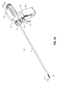
FIG. 1A is a side, perspective view of an ultrasonic surgical instrument provided in accordance with the present disclosure, wherein the tool assembly is disposed in an open condition; -
FIG. 1B is a side, perspective view of the ultrasonic surgical instrument ofFIG. 1A , wherein the tool assembly is disposed in a clamping condition; -
FIG. 2 is an exploded, perspective view of the shaft, waveguide, and tool assemblies of the ultrasonic surgical instrument ofFIG. 1A ; -
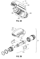
FIG. 3A is a side, perspective view of the ultrasonic transducer and generator assembly ("TAG") of the ultrasonic surgical instrument ofFIG. 1A ; -
FIG. 3B is an exploded, perspective view of the TAG of the ultrasonic surgical instrument ofFIG. 1A ; and -
FIG. 4 is a block diagram illustrating the power and signal communications between the TAG, battery assembly, and switch assembly of the ultrasonic surgical instrument ofFIG. 1A . - Referring generally to
FIGS. 1A-4 , an embodiment of an ultrasonic surgical instrument exemplifying the aspects and features of the present disclosure is shown generally identified byreference numeral 10. As detailed below, integrated within ultrasonicsurgical instrument 10 are features that enable automatic compensation for transducer aging, thus helping to ensure that ultrasonicsurgical instrument 10 enjoys consistent performance throughout its usable life. However, it is also contemplated that the transducer aging compensation features of the present disclosure be incorporated into or used with any other suitable ultrasonic surgical instrument, incorporated into an energy source, e.g., a stand-alone generator (not shown), associated with an ultrasonic surgical instrument, and/or utilized to allow for manual adjustment of the parameters and/or settings associated with the transducer of ultrasonicsurgical instrument 10 or other suitable ultrasonic surgical instrument. - For the purposes herein, ultrasonic
surgical instrument 10 is generally described. Aspects and features of ultrasonicsurgical instrument 10 not germane to the understanding of the transducer aging compensation features provided in accordance with the present disclosure are omitted to avoid obscuring such aspects and features of the present disclosure in unnecessary detail. - With reference to
FIGS. 1A-3B , ultrasonicsurgical instrument 10 generally includes ahandle assembly 12, anelongated body portion 14, and atool assembly 16.Tool assembly 16 includes ablade 32 and aclamp member 58.Handle assembly 12 supports abattery assembly 18 and an ultrasonic transducer and generator assembly ("TAG") 20, and includes arotatable nozzle 22, anactivation button 24, and aclamp trigger 26.Battery assembly 18 andTAG 20 are each releasably secured to handleassembly 12, and are removable therefrom to facilitate disposal of the entire device, with the exception ofbattery assembly 18 andTAG 20. However, it is contemplated that any or all of the components of ultrasonicsurgical instrument 10 be configured as disposable single-use components or sterilizable multi-use components. - Referring to
FIG. 2 in particular,elongated body portion 14 includes awaveguide 30 which extends distally fromhandle assembly 12 totool assembly 16. A distal end ofwaveguide 30 defines ablade 32. A proximal end ofwaveguide 30 is configured to engage TAG 20 (FIGS. 3A and 3B ), as detailed below. Anisolation tube 36 is positioned aboutwaveguide 30 to prevent the transfer of ultrasonic energy fromwaveguide 30 to aninner support tube 42.Waveguide 30 andinner support tube 42 are rotatably coupled to rotatable nozzle 22 (FIGS. 1A and1B ) such that rotation of nozzle 22 (FIGS. 1A and1B ) effects corresponding rotation ofinner support tube 42 andwaveguide 30. Anactuator tube 66 which, as detailed below, is coupled toinner support tube 42, is similarly rotated upon rotation of nozzle 22 (FIGS. 1A and1B ). -
Inner support tube 42 is positioned aboutisolation tube 36 and includes a distal end having a pair of spacedclamp support arms 52. Spacedclamp support arms 52 are configured to pivotally engage pivot members 56 (only one of which is visible inFIG. 2 ) formed onclamp member 58 oftool assembly 16 to enable pivoting ofclamp member 58 between an open position (FIG. 1A ), whereinclamp member 58 is spaced fromblade member 32, and a closed position (FIG. 1B ), whereinclamp member 58 is approximated relative toblade member 32.Clamp member 58 is moved between the open and closed positions in response to actuation of clamp trigger 26 (FIGS. 1A and1B ). -
Outer actuator tube 66 is slidably supported aboutinner support tube 42 and is operably coupled to clampmember 58 such that, asactuator tube 66 is slid aboutinner support tube 42 between an advanced position and a retracted position,clamp member 58 is pivoted from the open position (FIG. 1A ) to the closed position (FIG. 1B ). A proximal end ofouter actuator tube 66 is operably coupled withrotatable nozzle 22 such thatouter actuator tube 66 is rotatably secured to but slidable relative torotatable nozzle 22. The proximal end ofouter actuator tube 66 is also operably coupled with adrive mechanism 100. - Referring to
FIGS. 1A-2 , handleassembly 12 includesdrive mechanism 100 supported therein for linear movement relative to handleassembly 12. Handleassembly 12 also includes theaforementioned clamp trigger 26, which is operably coupled withdrive mechanism 100 such that, in use, when clampingtrigger 26 is compressed towards battery assembly 18 (FIG. 1B ),outer actuator tube 66 is moved from the advanced position to the retracted position to pivotclamp member 58 from the open position to the closed position in relation toblade 32. A spring (not explicitly shown) may be provided tobias clamping trigger 26 towards the initial position and, thus,clamp member 58 towards the open position (FIG. 1A ). - With additional reference to
FIG. 4 ,activation button 24 is supported onhandle assembly 12. Whenactivation button 24 is activated in an appropriate manner, an underlying two-mode switch assembly 170 is activated to effect communication betweenbattery assembly 18 andTAG 20 in either a "LOW" power mode or a "HIGH" power mode, depending upon the manner of activation ofactivation button 24. -
Battery assembly 18 is connected to a lower end ofhandle assembly 12 to define a fixed handgrip portion ofhandle assembly 12 and includes anouter housing 200 that houses one ormore battery cells 210, a safety circuit andfuel gauge board 230, abuck converter 240, and abattery microcontroller 250 including aclock 260. Safety circuit andfuel gauge board 230 ofbattery assembly 18 controls the charging and discharging ofbattery cells 210, monitors parameters ofbattery cells 210, and protectsbattery cells 210.Buck converter 240 andbattery microcontroller 250 are detailed below.Clock 260 may be configured as a real-time clock from which, in conjunction with the birthdate ofultrasonic transducer 350, e.g., time t = 0, the age ofultrasonic transducer 350 can be determined. A series of contacts (not explicitly shown) enable communication of power and/or control signals between the internal components ofbattery assembly 18, two-mode switch assembly 170, andTAG 20, although contactless communication therebetween is also contemplated. - Referring to
FIGS. 1A, 1B, and 3A-4 ,TAG 20 includes agenerator 300 and anultrasonic transducer 350.Generator 300 includes anouter housing 310 that houses aTAG microcontroller 330 having amemory 334.Memory 334 stores set point data corresponding to the "LOW" and "HIGH" power modes of ultrasonicsurgical instrument 10 as well as the "birthdate" ofultrasonic transducer 350 and aging compensation data in the form of one or more values, functions, tables, and/or multipliers. This data, in accordance with the age ofultrasonic transducer 350, as determined usingclock 260 ofbattery assembly 18 and the "birthdate" ofultrasonic transducer 350 stored inmemory 334 ofTAG microcontroller 330, are utilized to compensate for effects of aging ofultrasonic transducer 350 and correct the set point values accordingly, as detailed below. -
TAG 20 includessupport members 340 extending fromouter housing 310 that define cradles for rotatably supportingultrasonic transducer 350.Ultrasonic transducer 350 includes apiezoelectric stack 352 and a forwardly extendinghorn 354.Horn 354 is configured to threadably engage the proximal end of waveguide 30 (FIG. 2 ), although other suitable engagement mechanisms are also contemplated. A series of contacts (not explicitly shown) associated withTAG 20 enable communication of power and/or control signals betweenTAG 20,battery assembly 18, and two-mode switch assembly 170, although contactless communication therebetween is also contemplated. - In general, in use, when
battery assembly 18 andTAG 20 are attached to handleassembly 12 andwaveguide 30 and ultrasonicsurgical instrument 10 is activated,battery cells 210 provide power togenerator 300 ofTAG 20 which, in turn, uses this power to apply an AC signal toultrasonic transducer 350 ofTAG 20.Ultrasonic transducer 350, in turn, converts the AC signal into high frequency mechanical motion. This high frequency mechanical motion produced byultrasonic transducer 350 is transmitted toblade 32 viawaveguide 30 for application of such ultrasonic energy tissue adjacent to or clamped betweenblade 32 andclamp member 58 oftool assembly 16 to treat tissue. - More specifically, in use, when
activation button 24 is manipulated such thatswitch assembly 170 is activated in the "LOW" power mode,switch assembly 170signals TAG microcontroller 330 to providemicrocontroller 250 ofbattery assembly 18 with an amplitude value corresponding to the "LOW" power mode amplitude set point.Microcontroller 250 ofbattery assembly 18 regulates the current output frombuck converter 240 toTAG 20 in accordance with this "LOW" power mode amplitude value such that an appropriate current is applied toTAG 20 to enablegenerator 300 to generate a high voltage AC signal that is applied toultrasonic transducer 350 for producing a mechanical motion having an amplitude equal to a "LOW" power mode amplitude set point. Similarly, whenactivation button 24 is manipulated such thatswitch assembly 170 is activated in the "HIGH" power mode,switch assembly 170signals TAG microcontroller 330 to providemicrocontroller 250 ofbattery assembly 18 with an amplitude value corresponding to the "HIGH" power mode amplitude set point.Microcontroller 250 ofbattery assembly 18 regulates the current output frombuck converter 240 toTAG 20 in accordance with this "HIGH" power mode amplitude value such that an appropriate current is applied toTAG 20 to enablegenerator 300 to generate a high voltage AC signal that is applied toultrasonic transducer 350 for producing a mechanical motion having an amplitude equal to a "HIGH" power mode amplitude set point. -
Ultrasonic transducer 350, as noted above, includes apiezoelectric stack 352. It ispiezoelectric stack 352 ofultrasonic transducer 350 that converts the high voltage AC signal into mechanical motion that is transmitted fromultrasonic transducer 350, alongwaveguide 30, toblade 32 for treating tissue.Piezoelectric stack 352 includes a plurality ofpiezoelectric elements 356 stacked and bolted to one another under compression such that, in use, upon application of the high voltage AC signal topiezoelectric stack 352, thepiezoelectric elements 356 repeatedly deform and reform, thus producing the mechanical motion ofultrasonic transducer 350 that is output to waveguide 30 for transmission therealong toblade 32. - It has been found that, with respect to transducers including piezoelectric materials, aging of the transducer affects the amplitude of mechanical motion output from the transducer. Thus, with respect to
ultrasonic transducer 350, for example, if the "LOW" and "HIGH" power mode amplitude values provided tomicrocontroller 250 ofbattery assembly 18 are fixed at their respective set points throughout the usable life ofultrasonic transducer 350, the amplitude of the resulting mechanical motion produced byultrasonic transducer 350 may drift from these set points asultrasonic transducer 350 ages. In other words, the actual output may no longer be equal to the set point. Thus, correction is required to compensate for transducer aging. - Additionally, such aging, or at least a particular pattern of aging, has been determined to be a result of, and can be measured from, occurrence of an "event" associated with the ultrasonic transducer such as polarization, compression, or heating. With respect to
ultrasonic transducer 350 in particular, it has been found that bolting ofpiezoelectric elements 356 under compression to formpiezoelectric stack 352 is one such "event" and, accordingly, that the age ofultrasonic transducer 350 may be determined by setting the time at whichpiezoelectric elements 356 are bolted under compression, e.g., the "birthdate" ofultrasonic transducer 350, to time t = 0. Time t = 0 may be set by writing this "birthdate" time intomemory 334 ofTAG microcontroller 330, or in any other suitable fashion. The actual age ofultrasonic transducer 350 at any given point may be determined by comparing the "birthdate" time stored inmemory 334 with the time provided byclock 260 ofbattery assembly 18. Further, it is contemplated that other "events" such as polarization, heating, or another point during manufacturing, assembly, and/or use may also be utilized to mark time t = 0. - The aging characteristics of a transducer from a given "'event" or time t = 0 may be measured experimentally, estimated, or otherwise determined. Further, such aging effects may be represented by a value or values, e.g., a value(s) that is to be added to or subtracted from an original set point, and/or by an equation or equations, e.g., an equation(s) into which the original set point is input, that are used to correct the set points to compensate for transducer aging. With respect to
transducer 350, for example, experimental data has indicated that the output amplitude oftransducer 350 corresponding to an original set point "S0" increases as a function of time. Thus, in order to compensate for transducer aging and produce an output amplitude that is equal to the original set point "S0" for a given time, aging compensation is performed by subtracting a correction value "C" or correction function "C(t)" from the original set point "S0" to obtain an age-compensated, or corrected set point value "St" according to equations (1), wherein the correction is in the form of a value, or (2), wherein the correction is in the form of a function:

- More specifically, such experimental data has found that, for a "LOW" power mode original set point S0(LOW) = 0.00238 in, the output amplitude increases logarithmically for
time 10 ≤ t ≤ 100, wherein "t" is represented in days, in a manner such that aging compensation can be accomplished using equation (2), above, wherein the correction function "CLOW(t)" is provided according to equation (3):
time 10 ≤ t ≤ 100, wherein "t" is represented in days, in a manner such that aging compensation can be accomplished using equation (2), above, wherein the correction function "CHIGH(t)" is provided according to equation (4):
- For time t > 100 and the "LOW" power mode original set point S0(LOW) = 0.00238 in, an average offset value has been observed such that aging compensation can be accomplished using equation (1), above, wherein the correction value "CLOW" is provided by equation (5):

- For time t > 100 and the "HIGH" power mode original set point S0(HIGH) = 3.15 mm, an average offset value has been observed such that aging compensation can be accomplished using equation (1), above, wherein the correction value "CHIGH" is provided by equation (6):

- The above-noted equations and experimental data are provided for exemplary purposes only, as transducer aging for any given surgical instrument may vary depending upon the specifications and/or configuration of the particular transducer and/or other components of the surgical instrument. Further, experimental data need not be used but, rather, transducer aging information may be provided via estimations, simulations, projections, models, etc.
- As detailed below, based upon the transducer aging information and the correction offset values and/or functions, the original set point "S0" can be corrected to obtain a corrected set point value "St" such that the actual output amplitude of displacement of
ultrasonic transducer 350 can be maintained at the original set point "S0" despite aging ofultrasonic transducer 350. - The above-detailed information is stored in
memory 334 ofTAG microcontroller 330 for use in determining the corrected set point value "St" provided fromTAG microcontroller 330 tomicrocontroller 250 ofbattery assembly 18. More specifically, such information may be stored: as a function or functions from which, in conjunction with the age ofultrasonic transducer 350 as determined usingclock 260, the corrected set point value "St" may be calculated; as look-up table that correlates the corrected set point value "St" with the age ofultrasonic transducer 350 as determined usingclock 260; or in any other suitable fashion. As noted in the example above, a different function or value may be provided for a different time range, and/or for a different setting, e.g., the "LOW" power mode versus the "HIGH" power mode. - In use,
TAG microcontroller 350 accesses and/or determines the corrected set point value "St" corresponding to the age ofultrasonic transducer 350 and provides the corrected set point value "St" tomicrocontroller 250 ofbattery assembly 18. Such adjustment may be performed continuously, e.g., each time ultrasonicsurgical instrument 10 is activated, at periodic intervals, e.g., every 10 days, and/or manually, e.g., upon request. Further, it is contemplated thatTAG microcontroller 330 be externally accessible, e.g., wirelessly or via a wired connection, to enable updating and/or modification of the "birthdate" and/or age compensation information stored inmemory 334. - While several embodiments of the disclosure have been shown in the drawings, it is not intended that the disclosure be limited thereto, as it is intended that the disclosure be as broad in scope as the art will allow and that the specification be read likewise. Therefore, the above description should not be construed as limiting, but merely as exemplifications of particular embodiments. Those skilled in the art will envision other modifications within the scope and spirit of the claims appended hereto.
- The invention may be described by reference to the following numbered paragraphs:-
- 1. An ultrasonic surgical instrument, comprising:
- a housing;
- a waveguide having a proximal end and a distal end, the waveguide extending distally from the housing;
- an end effector coupled to the distal end of the waveguide;
- an ultrasonic transducer retained within the housing and coupled to the proximal end of the waveguide, the ultrasonic transducer configured to produce mechanical motion for transmission along the waveguide to the end effector; and
- a controller configured to control an amplitude of the mechanical motion of the ultrasonic transducer in accordance with at least one amplitude value, wherein the at least one amplitude value is adjusted according to an age of the ultrasonic transducer.
- 2. The ultrasonic surgical instrument according to paragraph 1, wherein the at least one amplitude value is adjusted to compensate for aging effects of the ultrasonic transducer in order to maintain constant the amplitude of the mechanical motion.
- 3. The ultrasonic surgical instrument according to paragraph 1, wherein the at least one amplitude value is decreased as the ultrasonic transducer ages.
- 4. The ultrasonic surgical instrument according to paragraph 1, wherein the at least one amplitude value is adjusted logarithmically with respect to an age of the ultrasonic transducer.
- 5. The ultrasonic surgical instrument according to paragraph 1, wherein the at least one amplitude value includes a first amplitude value corresponding to a low power mode and a second amplitude value corresponding to a high power mode.
- 6. The ultrasonic surgical instrument according to paragraph 1, wherein the controller includes a memory storing information indicating a time t = 0 from which an age of the ultrasonic transducer is determined, and wherein the time t = 0 corresponds to occurrence of a pre-determined event associated with the ultrasonic transducer.
- 7. The ultrasonic surgical instrument according to paragraph 6, wherein the ultrasonic transducer includes a piezoelectric stack, and wherein the time t = 0 corresponds to when the piezoelectric stack is secured under compression.
- 8. An assembly for use with an ultrasonic surgical instrument, the assembly including:
- an ultrasonic transducer configured to produce mechanical motion; and
- a controller configured to control an amplitude of the mechanical motion of the ultrasonic transducer in accordance with at least one amplitude value, the controller including a memory storing information indicating a time t = 0 from which an age of the ultrasonic transducer is determined, wherein the at least one amplitude value is adjusted according to the age of the ultrasonic transducer.
- 9. The assembly according to paragraph 8, wherein the at least one amplitude value is adjusted to compensate for aging effects of the ultrasonic transducer in order to maintain constant the amplitude of the mechanical motion.
- 10. The assembly according to paragraph 8, wherein the at least one amplitude value is decreased as the age of the ultrasonic transducer increases.
- 11. The assembly according to paragraph 8, wherein the at least one amplitude value is adjusted logarithmically with respect to the age of the ultrasonic transducer.
- 12. The assembly according to paragraph 8, wherein the time t = 0 corresponds to occurrence of a pre-determined event associated with the ultrasonic transducer.
- 13. The assembly according to
paragraph 12, wherein the ultrasonic transducer includes a piezoelectric stack, and wherein the time t = 0 corresponds to when the piezoelectric stack is secured under compression. - 14. A method of controlling an ultrasonic transducer for a surgical instrument, comprising:
- controlling an amplitude of mechanical motion of an ultrasonic transducer in accordance with at least one amplitude value;
- determining an age of the ultrasonic transducer; and
- adjusting the at least one amplitude value in accordance with the age of the ultrasonic transducer.
- 15. The method according to
paragraph 14, wherein determining the age of the ultrasonic transducer includes using a clock to measure the age of the ultrasonic transducer relative to a time t = 0. - 16. The method according to paragraph 15, wherein the time t = 0 corresponds to occurrence of a pre-determined event associated with the ultrasonic transducer.
- 17. The method according to
paragraph 16, wherein the ultrasonic transducer includes a piezoelectric stack, and wherein the time t = 0 corresponds to when the piezoelectric stack is secured under compression. - 18. The method according to
paragraph 14, wherein the at least one amplitude value is decreased as the age of the ultrasonic transducer increases.
Claims (15)
- An ultrasonic surgical instrument, comprising:a housing;a waveguide having a proximal end and a distal end, the waveguide extending distally from the housing;an end effector coupled to the distal end of the waveguide;an ultrasonic transducer retained within the housing and coupled to the proximal end of the waveguide, the ultrasonic transducer configured to produce mechanical motion for transmission along the waveguide to the end effector; anda controller configured to control an amplitude of the mechanical motion of the ultrasonic transducer in accordance with at least one amplitude value, wherein the at least one amplitude value is adjusted according to an age of the ultrasonic transducer.
- The ultrasonic surgical instrument according to claim 1, wherein the at least one amplitude value is adjusted to compensate for aging effects of the ultrasonic transducer in order to maintain constant the amplitude of the mechanical motion.
- The ultrasonic surgical instrument according to claim 1 or 2, wherein the at least one amplitude value is decreased as the ultrasonic transducer ages.
- The ultrasonic surgical instrument according to claim 1, 2 or 3 wherein the at least one amplitude value is adjusted logarithmically with respect to an age of the ultrasonic transducer.
- The ultrasonic surgical instrument according to any preceding claim, wherein the at least one amplitude value includes a first amplitude value corresponding to a low power mode and a second amplitude value corresponding to a high power mode.
- The ultrasonic surgical instrument according to any preceding claim, wherein the controller includes a memory storing information indicating a time t = 0 from which an age of the ultrasonic transducer is determined, and wherein the time t = 0 corresponds to occurrence of a pre-determined event associated with the ultrasonic transducer.
- The ultrasonic surgical instrument according to claim 6, wherein the ultrasonic transducer includes a piezoelectric stack, and wherein the time t = 0 corresponds to when the piezoelectric stack is secured under compression.
- An assembly for use with an ultrasonic surgical instrument, the assembly including:an ultrasonic transducer configured to produce mechanical motion; anda controller configured to control an amplitude of the mechanical motion of the ultrasonic transducer in accordance with at least one amplitude value, the controller including a memory storing information indicating a time t = 0 from which an age of the ultrasonic transducer is determined, wherein the at least one amplitude value is adjusted according to the age of the ultrasonic transducer.
- The assembly according to claim 8, wherein the at least one amplitude value is adjusted to compensate for aging effects of the ultrasonic transducer in order to maintain constant the amplitude of the mechanical motion.
- The assembly according to claim 8 or 9, wherein the at least one amplitude value is decreased as the age of the ultrasonic transducer increases.
- The assembly according to claim 8, 9 or 10, wherein the at least one amplitude value is adjusted logarithmically with respect to the age of the ultrasonic transducer.
- The assembly according to any one of claims 8 to 11, wherein the time t = 0 corresponds to occurrence of a pre-determined event associated with the ultrasonic transducer.
- The assembly according to claim 12, wherein the ultrasonic transducer includes a piezoelectric stack, and wherein the time t = 0 corresponds to when the piezoelectric stack is secured under compression.
- A method of controlling an ultrasonic transducer for a surgical instrument, comprising:controlling an amplitude of mechanical motion of an ultrasonic transducer in accordance with at least one amplitude value;determining an age of the ultrasonic transducer; andadjusting the at least one amplitude value in accordance with the age of the ultrasonic transducer.
- The method according to claim 14, wherein determining the age of the ultrasonic transducer includes using a clock to measure the age of the ultrasonic transducer relative to a time t = 0, preferably, wherein the time t = 0 corresponds to occurrence of a pre-determined event associated with the ultrasonic transducer and preferably, wherein the ultrasonic transducer includes a piezoelectric stack, and wherein the time t = 0 corresponds to when the piezoelectric stack is secured under compression.
Applications Claiming Priority (2)
| Application Number | Priority Date | Filing Date | Title |
|---|---|---|---|
| US201562105932P | 2015-01-21 | 2015-01-21 | |
| US14/971,321 US9943326B2 (en) | 2015-01-21 | 2015-12-16 | Ultrasonic surgical instruments and methods of compensating for transducer aging |
Publications (2)
| Publication Number | Publication Date |
|---|---|
| EP3048807A1 true EP3048807A1 (en) | 2016-07-27 |
| EP3048807B1 EP3048807B1 (en) | 2020-03-25 |
Family
ID=55129714
Family Applications (1)
| Application Number | Title | Priority Date | Filing Date |
|---|---|---|---|
| EP16151211.6A Active EP3048807B1 (en) | 2015-01-21 | 2016-01-14 | Ultrasonic surgical instruments of compensating for transducer aging |
Country Status (2)
| Country | Link |
|---|---|
| US (1) | US9943326B2 (en) |
| EP (1) | EP3048807B1 (en) |
Families Citing this family (7)
| Publication number | Priority date | Publication date | Assignee | Title |
|---|---|---|---|---|
| KR102457401B1 (en) | 2013-08-07 | 2022-10-21 | 스트리커 코포레이션 | System and method for driving an ultrasonic handpiece as a function of the mechanical impedance of the handpiece |
| US10603065B2 (en) | 2016-02-18 | 2020-03-31 | Covidien Lp | Surgical instruments and jaw members thereof |
| US10555750B2 (en) * | 2016-08-25 | 2020-02-11 | Ethicon Llc | Ultrasonic surgical instrument with replaceable blade having identification feature |
| US11331115B2 (en) * | 2018-10-03 | 2022-05-17 | Covidien Lp | Reusable ultrasonic transducer and generator assemblies, surgical instruments including the same, and methods of manufacturing the same |
| EP4117547A2 (en) * | 2020-03-12 | 2023-01-18 | Covidien LP | Systems and methods for operating a surgical device |
| AU2021353591A1 (en) | 2020-10-01 | 2023-02-02 | Stryker Corporation | Pulse control for ultrasonic tool systems |
| CN115568910B (en) * | 2022-09-26 | 2024-09-06 | 河南翔宇医疗设备股份有限公司 | Optimization method, device and equipment of ultrasonic debridement handle and readable storage medium |
Citations (3)
| Publication number | Priority date | Publication date | Assignee | Title |
|---|---|---|---|---|
| WO2007014183A2 (en) * | 2005-07-25 | 2007-02-01 | Piezoinnovations | Ultrasonic transducer control method and system |
| US20120110758A1 (en) * | 2010-11-04 | 2012-05-10 | Canon Kabushiki Kaisha | Driving method for piezoelectric vibrator, and dust removing device and ultrasonic motor using the driving method |
| WO2014178436A1 (en) * | 2013-05-02 | 2014-11-06 | オリンパスメディカルシステムズ株式会社 | Ultrasonic treatment system |
Family Cites Families (27)
| Publication number | Priority date | Publication date | Assignee | Title |
|---|---|---|---|---|
| US3839698A (en) | 1973-05-29 | 1974-10-01 | Raytheon Co | Transducer compensation network |
| DE3331896A1 (en) | 1983-09-03 | 1985-03-21 | Gerhard Prof. Dr.-Ing. 8012 Ottobrunn Flachenecker | POWER GENERATOR FOR AN ULTRASONIC transducer |
| JPS6196419A (en) | 1984-10-17 | 1986-05-15 | Chiyouonpa Kogyo Kk | Bomb level checker |
| DE3507672A1 (en) | 1985-03-05 | 1986-09-11 | Otto 6900 Heidelberg Meyer | Instrument with a surgical tool for severing or suturing tissues |
| DE3630478C1 (en) | 1986-09-06 | 1988-01-07 | Ultrasonics Schallfeld Messtec | Motion sensor for dynamic loudspeakers |
| JPS63302699A (en) | 1987-06-02 | 1988-12-09 | Yamaha Corp | Mfb device |
| JPH0234008A (en) | 1988-07-25 | 1990-02-05 | Olympus Optical Co Ltd | Driver for ultrasonic vibrator |
| JP3390034B2 (en) | 1992-09-30 | 2003-03-24 | オリンパス光学工業株式会社 | Ultrasound surgical handpiece |
| US5643353A (en) | 1994-05-31 | 1997-07-01 | Microfab Technologies, Inc. | Controlling depoling and aging of piezoelectric transducers |
| US5897569A (en) | 1997-04-16 | 1999-04-27 | Ethicon Endo-Surgery, Inc. | Ultrasonic generator with supervisory control circuitry |
| JP2002186901A (en) | 2000-12-21 | 2002-07-02 | Olympus Optical Co Ltd | Ultrasonic surgical equipment |
| JP4402270B2 (en) | 2000-08-02 | 2010-01-20 | オリンパス株式会社 | Ultrasonic coagulation and incision device |
| JP4020559B2 (en) | 2000-02-04 | 2007-12-12 | オリンパス株式会社 | Ultrasonic transducer drive |
| JP3696034B2 (en) | 2000-03-14 | 2005-09-14 | オリンパス株式会社 | Ultrasonic drive device and ultrasonic surgical device |
| JP3756726B2 (en) | 2000-06-05 | 2006-03-15 | オリンパス株式会社 | Ultrasonic transducer drive |
| JP2001346805A (en) | 2000-06-09 | 2001-12-18 | Olympus Optical Co Ltd | Ultrasonic surgical instrument |
| DE20118699U1 (en) | 2001-11-19 | 2003-04-03 | Söring GmbH, 25451 Quickborn | Converter retainer for a surgical instrument, especially ultrasound shears used in laparoscopic operations, whereby the converter retainer is connected to the sonotrode via a screw connection with an integral torque lock |
| DE20118698U1 (en) | 2001-11-19 | 2003-04-03 | Söring GmbH, 25451 Quickborn | Surgical instrument, in particular, in the form of ultrasound scissors used for laparoscopic operations, comprises a push rod fixed in the groove of a guide tube by means of a cover sleeve |
| DE20303776U1 (en) | 2003-03-07 | 2004-07-15 | Söring GmbH | Surgical instrument, in particular in the form of ultrasonic scissors usable in laparoscopic operations, comprises a blade consisting of at least two materials joined to one another |
| JP4343778B2 (en) | 2004-06-16 | 2009-10-14 | オリンパス株式会社 | Ultrasonic surgical device |
| DE202006020201U1 (en) | 2005-08-03 | 2008-03-20 | Neumeyer, Stefan, Dr. | Connection for releasably connecting a tool with a dental handpiece and connection between the tool and the dental handpiece |
| KR100922760B1 (en) | 2008-03-03 | 2009-10-21 | 삼성모바일디스플레이주식회사 | Organic light emitting device |
| US8372100B2 (en) * | 2009-06-19 | 2013-02-12 | Olympus Medical Systems Corp. | Ultrasound surgical apparatus and calibration method therefor |
| CA2774751C (en) * | 2011-04-15 | 2018-11-06 | Covidien Ag | Battery powered hand-held ultrasonic surgical cautery cutting device |
| JP5816464B2 (en) | 2011-06-07 | 2015-11-18 | オリンパス株式会社 | Insertion device |
| US9622767B2 (en) | 2013-09-11 | 2017-04-18 | Covidien Lp | Ultrasonic surgical instrument with cooling system |
| US9655641B2 (en) | 2013-09-11 | 2017-05-23 | Covidien Lp | Ultrasonic surgical instrument with cooling system |
-
2015
- 2015-12-16 US US14/971,321 patent/US9943326B2/en active Active
-
2016
- 2016-01-14 EP EP16151211.6A patent/EP3048807B1/en active Active
Patent Citations (5)
| Publication number | Priority date | Publication date | Assignee | Title |
|---|---|---|---|---|
| WO2007014183A2 (en) * | 2005-07-25 | 2007-02-01 | Piezoinnovations | Ultrasonic transducer control method and system |
| US20120110758A1 (en) * | 2010-11-04 | 2012-05-10 | Canon Kabushiki Kaisha | Driving method for piezoelectric vibrator, and dust removing device and ultrasonic motor using the driving method |
| JP2012096193A (en) * | 2010-11-04 | 2012-05-24 | Canon Inc | Driving method for piezoelectric vibrator, dust removing device by the driving method, and ultrasonic motor |
| WO2014178436A1 (en) * | 2013-05-02 | 2014-11-06 | オリンパスメディカルシステムズ株式会社 | Ultrasonic treatment system |
| US20150201960A1 (en) * | 2013-05-02 | 2015-07-23 | Olympus Medical Systems Corp. | Ultrasonic treatment system |
Also Published As
| Publication number | Publication date |
|---|---|
| US9943326B2 (en) | 2018-04-17 |
| EP3048807B1 (en) | 2020-03-25 |
| US20160206343A1 (en) | 2016-07-21 |
Similar Documents
| Publication | Publication Date | Title |
|---|---|---|
| EP3048807B1 (en) | Ultrasonic surgical instruments of compensating for transducer aging | |
| US20250352236A1 (en) | Haptic feedback devices for surgical robot | |
| CN103237512B (en) | devices and techniques for cutting and coagulating tissue | |
| EP2992847B1 (en) | Ultrasonic treatment system | |
| US10194972B2 (en) | Managing tissue treatment | |
| US9788851B2 (en) | Surgical instrument with tissue density sensing | |
| JP6328647B2 (en) | Surgeon feedback detection method and display method (SURGEONEDEDBACKSENSINGANDDISPLAYMETHODS) | |
| CN102119005B (en) | Ultrasonic device for cutting and coagulating with stepped output | |
| EP2371314B1 (en) | Electrosurgical system with means for tracking the usage of a reposable instrument | |
| JP2006280953A (en) | Ultrasonic clipping cutting instrument for surgery use | |
| CN115005934B (en) | Control method and control device of ultrasonic transducer | |
| US8662745B2 (en) | Methods of measuring conditions of an ultrasonic instrument | |
| ES2998497T3 (en) | Electrosurgical generator control system | |
| US20070035203A1 (en) | Ultrasonic transducer control method and system | |
| US11123094B2 (en) | Ultrasonic surgical instruments and methods for sealing and/or cutting tissue | |
| US20100324580A1 (en) | Ultrasound surgical apparatus and calibration method therefor | |
| CN217987660U (en) | Wireless chargeable ultrasonic knife | |
| US11806038B2 (en) | Surgical instrument and method facilitating testing jaw force of the surgical instrument | |
| CN223979814U (en) | An easily adjustable measuring device for orthopedic surgery | |
| KR101744435B1 (en) | Ultrasonic surgery | |
| KR20220069452A (en) | Ultrasound operating equipment with Improved hemostatic function |
Legal Events
| Date | Code | Title | Description |
|---|---|---|---|
| PUAI | Public reference made under article 153(3) epc to a published international application that has entered the european phase |
Free format text: ORIGINAL CODE: 0009012 |
|
| 17P | Request for examination filed |
Effective date: 20160114 |
|
| AK | Designated contracting states |
Kind code of ref document: A1 Designated state(s): AL AT BE BG CH CY CZ DE DK EE ES FI FR GB GR HR HU IE IS IT LI LT LU LV MC MK MT NL NO PL PT RO RS SE SI SK SM TR |
|
| AX | Request for extension of the european patent |
Extension state: BA ME |
|
| RBV | Designated contracting states (corrected) |
Designated state(s): AL AT BE BG CH CY CZ DE DK EE ES FI FR GB GR HR HU IE IS IT LI LT LU LV MC MK MT NL NO PL PT RO RS SE SI SK SM TR |
|
| STAA | Information on the status of an ep patent application or granted ep patent |
Free format text: STATUS: EXAMINATION IS IN PROGRESS |
|
| 17Q | First examination report despatched |
Effective date: 20190313 |
|
| REG | Reference to a national code |
Ref country code: DE Ref legal event code: R079 Ref document number: 602016032355 Country of ref document: DE Free format text: PREVIOUS MAIN CLASS: H04R0003000000 Ipc: A61B0017320000 |
|
| GRAP | Despatch of communication of intention to grant a patent |
Free format text: ORIGINAL CODE: EPIDOSNIGR1 |
|
| STAA | Information on the status of an ep patent application or granted ep patent |
Free format text: STATUS: GRANT OF PATENT IS INTENDED |
|
| RIC1 | Information provided on ipc code assigned before grant |
Ipc: A61B 17/32 20060101AFI20190925BHEP Ipc: H04R 3/00 20060101ALI20190925BHEP Ipc: A61B 90/00 20160101ALN20190925BHEP Ipc: B06B 1/02 20060101ALI20190925BHEP |
|
| INTG | Intention to grant announced |
Effective date: 20191011 |
|
| GRAS | Grant fee paid |
Free format text: ORIGINAL CODE: EPIDOSNIGR3 |
|
| GRAA | (expected) grant |
Free format text: ORIGINAL CODE: 0009210 |
|
| STAA | Information on the status of an ep patent application or granted ep patent |
Free format text: STATUS: THE PATENT HAS BEEN GRANTED |
|
| AK | Designated contracting states |
Kind code of ref document: B1 Designated state(s): AL AT BE BG CH CY CZ DE DK EE ES FI FR GB GR HR HU IE IS IT LI LT LU LV MC MK MT NL NO PL PT RO RS SE SI SK SM TR |
|
| REG | Reference to a national code |
Ref country code: GB Ref legal event code: FG4D |
|
| REG | Reference to a national code |
Ref country code: AT Ref legal event code: REF Ref document number: 1247655 Country of ref document: AT Kind code of ref document: T Effective date: 20200415 Ref country code: IE Ref legal event code: FG4D |
|
| REG | Reference to a national code |
Ref country code: DE Ref legal event code: R096 Ref document number: 602016032355 Country of ref document: DE |
|
| PG25 | Lapsed in a contracting state [announced via postgrant information from national office to epo] |
Ref country code: FI Free format text: LAPSE BECAUSE OF FAILURE TO SUBMIT A TRANSLATION OF THE DESCRIPTION OR TO PAY THE FEE WITHIN THE PRESCRIBED TIME-LIMIT Effective date: 20200325 Ref country code: NO Free format text: LAPSE BECAUSE OF FAILURE TO SUBMIT A TRANSLATION OF THE DESCRIPTION OR TO PAY THE FEE WITHIN THE PRESCRIBED TIME-LIMIT Effective date: 20200625 Ref country code: RS Free format text: LAPSE BECAUSE OF FAILURE TO SUBMIT A TRANSLATION OF THE DESCRIPTION OR TO PAY THE FEE WITHIN THE PRESCRIBED TIME-LIMIT Effective date: 20200325 |
|
| PG25 | Lapsed in a contracting state [announced via postgrant information from national office to epo] |
Ref country code: BG Free format text: LAPSE BECAUSE OF FAILURE TO SUBMIT A TRANSLATION OF THE DESCRIPTION OR TO PAY THE FEE WITHIN THE PRESCRIBED TIME-LIMIT Effective date: 20200625 Ref country code: HR Free format text: LAPSE BECAUSE OF FAILURE TO SUBMIT A TRANSLATION OF THE DESCRIPTION OR TO PAY THE FEE WITHIN THE PRESCRIBED TIME-LIMIT Effective date: 20200325 Ref country code: GR Free format text: LAPSE BECAUSE OF FAILURE TO SUBMIT A TRANSLATION OF THE DESCRIPTION OR TO PAY THE FEE WITHIN THE PRESCRIBED TIME-LIMIT Effective date: 20200626 Ref country code: LV Free format text: LAPSE BECAUSE OF FAILURE TO SUBMIT A TRANSLATION OF THE DESCRIPTION OR TO PAY THE FEE WITHIN THE PRESCRIBED TIME-LIMIT Effective date: 20200325 Ref country code: SE Free format text: LAPSE BECAUSE OF FAILURE TO SUBMIT A TRANSLATION OF THE DESCRIPTION OR TO PAY THE FEE WITHIN THE PRESCRIBED TIME-LIMIT Effective date: 20200325 |
|
| REG | Reference to a national code |
Ref country code: NL Ref legal event code: MP Effective date: 20200325 |
|
| REG | Reference to a national code |
Ref country code: LT Ref legal event code: MG4D |
|
| PG25 | Lapsed in a contracting state [announced via postgrant information from national office to epo] |
Ref country code: NL Free format text: LAPSE BECAUSE OF FAILURE TO SUBMIT A TRANSLATION OF THE DESCRIPTION OR TO PAY THE FEE WITHIN THE PRESCRIBED TIME-LIMIT Effective date: 20200325 |
|
| PG25 | Lapsed in a contracting state [announced via postgrant information from national office to epo] |
Ref country code: SM Free format text: LAPSE BECAUSE OF FAILURE TO SUBMIT A TRANSLATION OF THE DESCRIPTION OR TO PAY THE FEE WITHIN THE PRESCRIBED TIME-LIMIT Effective date: 20200325 Ref country code: EE Free format text: LAPSE BECAUSE OF FAILURE TO SUBMIT A TRANSLATION OF THE DESCRIPTION OR TO PAY THE FEE WITHIN THE PRESCRIBED TIME-LIMIT Effective date: 20200325 Ref country code: LT Free format text: LAPSE BECAUSE OF FAILURE TO SUBMIT A TRANSLATION OF THE DESCRIPTION OR TO PAY THE FEE WITHIN THE PRESCRIBED TIME-LIMIT Effective date: 20200325 Ref country code: PT Free format text: LAPSE BECAUSE OF FAILURE TO SUBMIT A TRANSLATION OF THE DESCRIPTION OR TO PAY THE FEE WITHIN THE PRESCRIBED TIME-LIMIT Effective date: 20200818 Ref country code: CZ Free format text: LAPSE BECAUSE OF FAILURE TO SUBMIT A TRANSLATION OF THE DESCRIPTION OR TO PAY THE FEE WITHIN THE PRESCRIBED TIME-LIMIT Effective date: 20200325 Ref country code: IS Free format text: LAPSE BECAUSE OF FAILURE TO SUBMIT A TRANSLATION OF THE DESCRIPTION OR TO PAY THE FEE WITHIN THE PRESCRIBED TIME-LIMIT Effective date: 20200725 Ref country code: RO Free format text: LAPSE BECAUSE OF FAILURE TO SUBMIT A TRANSLATION OF THE DESCRIPTION OR TO PAY THE FEE WITHIN THE PRESCRIBED TIME-LIMIT Effective date: 20200325 Ref country code: SK Free format text: LAPSE BECAUSE OF FAILURE TO SUBMIT A TRANSLATION OF THE DESCRIPTION OR TO PAY THE FEE WITHIN THE PRESCRIBED TIME-LIMIT Effective date: 20200325 |
|
| REG | Reference to a national code |
Ref country code: AT Ref legal event code: MK05 Ref document number: 1247655 Country of ref document: AT Kind code of ref document: T Effective date: 20200325 |
|
| REG | Reference to a national code |
Ref country code: DE Ref legal event code: R097 Ref document number: 602016032355 Country of ref document: DE |
|
| PG25 | Lapsed in a contracting state [announced via postgrant information from national office to epo] |
Ref country code: DK Free format text: LAPSE BECAUSE OF FAILURE TO SUBMIT A TRANSLATION OF THE DESCRIPTION OR TO PAY THE FEE WITHIN THE PRESCRIBED TIME-LIMIT Effective date: 20200325 Ref country code: IT Free format text: LAPSE BECAUSE OF FAILURE TO SUBMIT A TRANSLATION OF THE DESCRIPTION OR TO PAY THE FEE WITHIN THE PRESCRIBED TIME-LIMIT Effective date: 20200325 Ref country code: ES Free format text: LAPSE BECAUSE OF FAILURE TO SUBMIT A TRANSLATION OF THE DESCRIPTION OR TO PAY THE FEE WITHIN THE PRESCRIBED TIME-LIMIT Effective date: 20200325 Ref country code: AT Free format text: LAPSE BECAUSE OF FAILURE TO SUBMIT A TRANSLATION OF THE DESCRIPTION OR TO PAY THE FEE WITHIN THE PRESCRIBED TIME-LIMIT Effective date: 20200325 |
|
| PGFP | Annual fee paid to national office [announced via postgrant information from national office to epo] |
Ref country code: GB Payment date: 20201218 Year of fee payment: 6 |
|
| PLBE | No opposition filed within time limit |
Free format text: ORIGINAL CODE: 0009261 |
|
| STAA | Information on the status of an ep patent application or granted ep patent |
Free format text: STATUS: NO OPPOSITION FILED WITHIN TIME LIMIT |
|
| PG25 | Lapsed in a contracting state [announced via postgrant information from national office to epo] |
Ref country code: PL Free format text: LAPSE BECAUSE OF FAILURE TO SUBMIT A TRANSLATION OF THE DESCRIPTION OR TO PAY THE FEE WITHIN THE PRESCRIBED TIME-LIMIT Effective date: 20200325 |
|
| 26N | No opposition filed |
Effective date: 20210112 |
|
| PG25 | Lapsed in a contracting state [announced via postgrant information from national office to epo] |
Ref country code: SI Free format text: LAPSE BECAUSE OF FAILURE TO SUBMIT A TRANSLATION OF THE DESCRIPTION OR TO PAY THE FEE WITHIN THE PRESCRIBED TIME-LIMIT Effective date: 20200325 |
|
| PG25 | Lapsed in a contracting state [announced via postgrant information from national office to epo] |
Ref country code: MC Free format text: LAPSE BECAUSE OF FAILURE TO SUBMIT A TRANSLATION OF THE DESCRIPTION OR TO PAY THE FEE WITHIN THE PRESCRIBED TIME-LIMIT Effective date: 20200325 |
|
| REG | Reference to a national code |
Ref country code: CH Ref legal event code: PL |
|
| PG25 | Lapsed in a contracting state [announced via postgrant information from national office to epo] |
Ref country code: LU Free format text: LAPSE BECAUSE OF NON-PAYMENT OF DUE FEES Effective date: 20210114 |
|
| REG | Reference to a national code |
Ref country code: BE Ref legal event code: MM Effective date: 20210131 |
|
| PG25 | Lapsed in a contracting state [announced via postgrant information from national office to epo] |
Ref country code: CH Free format text: LAPSE BECAUSE OF NON-PAYMENT OF DUE FEES Effective date: 20210131 Ref country code: LI Free format text: LAPSE BECAUSE OF NON-PAYMENT OF DUE FEES Effective date: 20210131 |
|
| PG25 | Lapsed in a contracting state [announced via postgrant information from national office to epo] |
Ref country code: IE Free format text: LAPSE BECAUSE OF NON-PAYMENT OF DUE FEES Effective date: 20210114 |
|
| PG25 | Lapsed in a contracting state [announced via postgrant information from national office to epo] |
Ref country code: BE Free format text: LAPSE BECAUSE OF NON-PAYMENT OF DUE FEES Effective date: 20210131 |
|
| GBPC | Gb: european patent ceased through non-payment of renewal fee |
Effective date: 20220114 |
|
| PG25 | Lapsed in a contracting state [announced via postgrant information from national office to epo] |
Ref country code: GB Free format text: LAPSE BECAUSE OF NON-PAYMENT OF DUE FEES Effective date: 20220114 |
|
| PG25 | Lapsed in a contracting state [announced via postgrant information from national office to epo] |
Ref country code: HU Free format text: LAPSE BECAUSE OF FAILURE TO SUBMIT A TRANSLATION OF THE DESCRIPTION OR TO PAY THE FEE WITHIN THE PRESCRIBED TIME-LIMIT; INVALID AB INITIO Effective date: 20160114 |
|
| PG25 | Lapsed in a contracting state [announced via postgrant information from national office to epo] |
Ref country code: CY Free format text: LAPSE BECAUSE OF FAILURE TO SUBMIT A TRANSLATION OF THE DESCRIPTION OR TO PAY THE FEE WITHIN THE PRESCRIBED TIME-LIMIT Effective date: 20200325 |
|
| PG25 | Lapsed in a contracting state [announced via postgrant information from national office to epo] |
Ref country code: MK Free format text: LAPSE BECAUSE OF FAILURE TO SUBMIT A TRANSLATION OF THE DESCRIPTION OR TO PAY THE FEE WITHIN THE PRESCRIBED TIME-LIMIT Effective date: 20200325 |
|
| PG25 | Lapsed in a contracting state [announced via postgrant information from national office to epo] |
Ref country code: MT Free format text: LAPSE BECAUSE OF FAILURE TO SUBMIT A TRANSLATION OF THE DESCRIPTION OR TO PAY THE FEE WITHIN THE PRESCRIBED TIME-LIMIT Effective date: 20200325 |
|
| PG25 | Lapsed in a contracting state [announced via postgrant information from national office to epo] |
Ref country code: TR Free format text: LAPSE BECAUSE OF FAILURE TO SUBMIT A TRANSLATION OF THE DESCRIPTION OR TO PAY THE FEE WITHIN THE PRESCRIBED TIME-LIMIT Effective date: 20200325 |
|
| PGFP | Annual fee paid to national office [announced via postgrant information from national office to epo] |
Ref country code: FR Payment date: 20251217 Year of fee payment: 11 |
|
| PGFP | Annual fee paid to national office [announced via postgrant information from national office to epo] |
Ref country code: DE Payment date: 20251217 Year of fee payment: 11 |