EP3048681A1 - Transient wavelength drift reduction in semiconductor lasers - Google Patents
Transient wavelength drift reduction in semiconductor lasers Download PDFInfo
- Publication number
- EP3048681A1 EP3048681A1 EP15305986.0A EP15305986A EP3048681A1 EP 3048681 A1 EP3048681 A1 EP 3048681A1 EP 15305986 A EP15305986 A EP 15305986A EP 3048681 A1 EP3048681 A1 EP 3048681A1
- Authority
- EP
- European Patent Office
- Prior art keywords
- region
- semiconductor region
- semiconductor
- laser
- drive current
- Prior art date
- Legal status (The legal status is an assumption and is not a legal conclusion. Google has not performed a legal analysis and makes no representation as to the accuracy of the status listed.)
- Withdrawn
Links
- 239000004065 semiconductor Substances 0.000 title claims abstract description 355
- 230000001052 transient effect Effects 0.000 title description 3
- 238000010438 heat treatment Methods 0.000 claims abstract description 148
- 230000005540 biological transmission Effects 0.000 claims abstract description 63
- 230000003287 optical effect Effects 0.000 claims abstract description 36
- 238000000034 method Methods 0.000 claims abstract description 28
- 230000020169 heat generation Effects 0.000 claims description 31
- 239000000463 material Substances 0.000 claims description 15
- 238000012546 transfer Methods 0.000 claims description 10
- 239000000203 mixture Substances 0.000 claims description 4
- 230000000116 mitigating effect Effects 0.000 abstract description 13
- 238000010586 diagram Methods 0.000 description 21
- 230000000712 assembly Effects 0.000 description 15
- 238000000429 assembly Methods 0.000 description 15
- 238000012935 Averaging Methods 0.000 description 11
- 239000013307 optical fiber Substances 0.000 description 5
- 230000036962 time dependent Effects 0.000 description 5
- GPXJNWSHGFTCBW-UHFFFAOYSA-N Indium phosphide Chemical compound [In]#P GPXJNWSHGFTCBW-UHFFFAOYSA-N 0.000 description 4
- 238000010893 electron trap Methods 0.000 description 4
- 238000002347 injection Methods 0.000 description 4
- 239000007924 injection Substances 0.000 description 4
- 229910018487 Ni—Cr Inorganic materials 0.000 description 3
- VNNRSPGTAMTISX-UHFFFAOYSA-N chromium nickel Chemical compound [Cr].[Ni] VNNRSPGTAMTISX-UHFFFAOYSA-N 0.000 description 3
- 238000001816 cooling Methods 0.000 description 3
- BASFCYQUMIYNBI-UHFFFAOYSA-N platinum Chemical compound [Pt] BASFCYQUMIYNBI-UHFFFAOYSA-N 0.000 description 3
- 239000011651 chromium Substances 0.000 description 2
- 230000004907 flux Effects 0.000 description 2
- 238000009413 insulation Methods 0.000 description 2
- 230000002045 lasting effect Effects 0.000 description 2
- VYZAMTAEIAYCRO-UHFFFAOYSA-N Chromium Chemical compound [Cr] VYZAMTAEIAYCRO-UHFFFAOYSA-N 0.000 description 1
- 238000010521 absorption reaction Methods 0.000 description 1
- 238000013459 approach Methods 0.000 description 1
- 230000015556 catabolic process Effects 0.000 description 1
- 229910052804 chromium Inorganic materials 0.000 description 1
- 230000007423 decrease Effects 0.000 description 1
- 238000006731 degradation reaction Methods 0.000 description 1
- 238000013461 design Methods 0.000 description 1
- 230000000694 effects Effects 0.000 description 1
- 238000004093 laser heating Methods 0.000 description 1
- 238000004519 manufacturing process Methods 0.000 description 1
- 238000005259 measurement Methods 0.000 description 1
- 229910052697 platinum Inorganic materials 0.000 description 1
- 238000012545 processing Methods 0.000 description 1
- 230000006798 recombination Effects 0.000 description 1
- 238000005215 recombination Methods 0.000 description 1
- 238000004088 simulation Methods 0.000 description 1
- 230000006641 stabilisation Effects 0.000 description 1
- 238000011105 stabilization Methods 0.000 description 1
Images


Classifications
-
- H—ELECTRICITY
- H01—ELECTRIC ELEMENTS
- H01S—DEVICES USING THE PROCESS OF LIGHT AMPLIFICATION BY STIMULATED EMISSION OF RADIATION [LASER] TO AMPLIFY OR GENERATE LIGHT; DEVICES USING STIMULATED EMISSION OF ELECTROMAGNETIC RADIATION IN WAVE RANGES OTHER THAN OPTICAL
- H01S5/00—Semiconductor lasers
- H01S5/02—Structural details or components not essential to laser action
- H01S5/024—Arrangements for thermal management
- H01S5/02453—Heating, e.g. the laser is heated for stabilisation against temperature fluctuations of the environment
-
- H—ELECTRICITY
- H01—ELECTRIC ELEMENTS
- H01S—DEVICES USING THE PROCESS OF LIGHT AMPLIFICATION BY STIMULATED EMISSION OF RADIATION [LASER] TO AMPLIFY OR GENERATE LIGHT; DEVICES USING STIMULATED EMISSION OF ELECTROMAGNETIC RADIATION IN WAVE RANGES OTHER THAN OPTICAL
- H01S3/00—Lasers, i.e. devices using stimulated emission of electromagnetic radiation in the infrared, visible or ultraviolet wave range
- H01S3/0007—Applications not otherwise provided for
-
- H—ELECTRICITY
- H01—ELECTRIC ELEMENTS
- H01S—DEVICES USING THE PROCESS OF LIGHT AMPLIFICATION BY STIMULATED EMISSION OF RADIATION [LASER] TO AMPLIFY OR GENERATE LIGHT; DEVICES USING STIMULATED EMISSION OF ELECTROMAGNETIC RADIATION IN WAVE RANGES OTHER THAN OPTICAL
- H01S3/00—Lasers, i.e. devices using stimulated emission of electromagnetic radiation in the infrared, visible or ultraviolet wave range
- H01S3/09—Processes or apparatus for excitation, e.g. pumping
- H01S3/097—Processes or apparatus for excitation, e.g. pumping by gas discharge of a gas laser
- H01S3/09702—Details of the driver electronics and electric discharge circuits
-
- H—ELECTRICITY
- H01—ELECTRIC ELEMENTS
- H01S—DEVICES USING THE PROCESS OF LIGHT AMPLIFICATION BY STIMULATED EMISSION OF RADIATION [LASER] TO AMPLIFY OR GENERATE LIGHT; DEVICES USING STIMULATED EMISSION OF ELECTROMAGNETIC RADIATION IN WAVE RANGES OTHER THAN OPTICAL
- H01S3/00—Lasers, i.e. devices using stimulated emission of electromagnetic radiation in the infrared, visible or ultraviolet wave range
- H01S3/10—Controlling the intensity, frequency, phase, polarisation or direction of the emitted radiation, e.g. switching, gating, modulating or demodulating
- H01S3/102—Controlling the intensity, frequency, phase, polarisation or direction of the emitted radiation, e.g. switching, gating, modulating or demodulating by controlling the active medium, e.g. by controlling the processes or apparatus for excitation
- H01S3/1026—Controlling the active medium by translation or rotation, e.g. to remove heat from that part of the active medium that is situated on the resonator axis
-
- H—ELECTRICITY
- H01—ELECTRIC ELEMENTS
- H01S—DEVICES USING THE PROCESS OF LIGHT AMPLIFICATION BY STIMULATED EMISSION OF RADIATION [LASER] TO AMPLIFY OR GENERATE LIGHT; DEVICES USING STIMULATED EMISSION OF ELECTROMAGNETIC RADIATION IN WAVE RANGES OTHER THAN OPTICAL
- H01S5/00—Semiconductor lasers
- H01S5/06—Arrangements for controlling the laser output parameters, e.g. by operating on the active medium
- H01S5/0607—Arrangements for controlling the laser output parameters, e.g. by operating on the active medium by varying physical parameters other than the potential of the electrodes, e.g. by an electric or magnetic field, mechanical deformation, pressure, light, temperature
- H01S5/0612—Arrangements for controlling the laser output parameters, e.g. by operating on the active medium by varying physical parameters other than the potential of the electrodes, e.g. by an electric or magnetic field, mechanical deformation, pressure, light, temperature controlled by temperature
-
- H—ELECTRICITY
- H01—ELECTRIC ELEMENTS
- H01S—DEVICES USING THE PROCESS OF LIGHT AMPLIFICATION BY STIMULATED EMISSION OF RADIATION [LASER] TO AMPLIFY OR GENERATE LIGHT; DEVICES USING STIMULATED EMISSION OF ELECTROMAGNETIC RADIATION IN WAVE RANGES OTHER THAN OPTICAL
- H01S5/00—Semiconductor lasers
- H01S5/06—Arrangements for controlling the laser output parameters, e.g. by operating on the active medium
- H01S5/062—Arrangements for controlling the laser output parameters, e.g. by operating on the active medium by varying the potential of the electrodes
- H01S5/0625—Arrangements for controlling the laser output parameters, e.g. by operating on the active medium by varying the potential of the electrodes in multi-section lasers
-
- H—ELECTRICITY
- H01—ELECTRIC ELEMENTS
- H01S—DEVICES USING THE PROCESS OF LIGHT AMPLIFICATION BY STIMULATED EMISSION OF RADIATION [LASER] TO AMPLIFY OR GENERATE LIGHT; DEVICES USING STIMULATED EMISSION OF ELECTROMAGNETIC RADIATION IN WAVE RANGES OTHER THAN OPTICAL
- H01S5/00—Semiconductor lasers
- H01S5/06—Arrangements for controlling the laser output parameters, e.g. by operating on the active medium
- H01S5/068—Stabilisation of laser output parameters
-
- H—ELECTRICITY
- H01—ELECTRIC ELEMENTS
- H01S—DEVICES USING THE PROCESS OF LIGHT AMPLIFICATION BY STIMULATED EMISSION OF RADIATION [LASER] TO AMPLIFY OR GENERATE LIGHT; DEVICES USING STIMULATED EMISSION OF ELECTROMAGNETIC RADIATION IN WAVE RANGES OTHER THAN OPTICAL
- H01S5/00—Semiconductor lasers
- H01S5/02—Structural details or components not essential to laser action
- H01S5/026—Monolithically integrated components, e.g. waveguides, monitoring photo-detectors, drivers
- H01S5/0261—Non-optical elements, e.g. laser driver components, heaters
-
- H—ELECTRICITY
- H01—ELECTRIC ELEMENTS
- H01S—DEVICES USING THE PROCESS OF LIGHT AMPLIFICATION BY STIMULATED EMISSION OF RADIATION [LASER] TO AMPLIFY OR GENERATE LIGHT; DEVICES USING STIMULATED EMISSION OF ELECTROMAGNETIC RADIATION IN WAVE RANGES OTHER THAN OPTICAL
- H01S5/00—Semiconductor lasers
- H01S5/04—Processes or apparatus for excitation, e.g. pumping, e.g. by electron beams
- H01S5/042—Electrical excitation ; Circuits therefor
- H01S5/0427—Electrical excitation ; Circuits therefor for applying modulation to the laser
Definitions
- This application relates to laser assemblies (laser modules) comprising semiconductor lasers, particularly for use in burst-mode operation, and to methods for driving semiconductor lasers, particularly in burst-mode operation.
- laser modules comprising directly modulated lasers (DMLs) and externally modulated lasers (EMLs).
- DMLs directly modulated lasers
- EMLs externally modulated lasers
- Directly tunable lasers such as e.g. distributed feedback (DFB) lasers and to some degree also other laser types such as EMLs suffer from self-heating induced wavelength drifts during burst-mode operation.
- DFB distributed feedback
- this drift results in signal degradations when signals generated by these lasers are passed through narrowband wavelength filters at the receive side, e.g. at the optical line termination (OLT) in a time and wavelength division multiplexed passive optical network (TWDM-PON).
- OLT optical line termination
- TWDM-PON time and wavelength division multiplexed passive optical network
- RSSI received signal strength indication
- the present document proposes a laser assembly and a method of driving a semiconductor laser having the features of the respective independent claims.
- the laser assembly may comprise a semiconductor laser and a drive unit for driving the semiconductor laser.
- the semiconductor laser may comprise a first semiconductor region for generating or modulating an optical signal in response to a first drive current that is injected (applied) to the first semiconductor region and a heating region that is arranged in proximity to the first semiconductor region and electrically insulated from the first semiconductor region.
- the drive unit may be configured to generate the first drive current and a second drive current, inject (apply) the first drive current to the first semiconductor region during respective transmission periods (data bursts) of the semiconductor laser, and inject (apply) the second drive current to the heating region in intervals between successive transmission periods (inter burst gaps, IBGs).
- the heating region may be configured to have characteristics of heat generation that are matched to those of the first semiconductor region, e.g. the heating region and the first semiconductor region may have substantially the same characteristics of heat generation.
- the heating region may be for example a second semiconductor region, a parallel waveguide or a metallic heater made of resistive material.
- the heating region may be configured to not emit any light when injected with the second drive current (i.e. may be optically inactive, e.g. due to including deep electron traps or being appropriately doped otherwise), or to not emit any light that would be coupled into an optical fiber that is attachable to the semiconductor laser to receive the optical signal generated or modulated by the first semiconductor region. This may require optically insulating the heating region from the first semiconductor region.
- the first semiconductor region may be referred to as an active region, whereas the heating region may be referred to as a passive region, or dummy region.
- heat is generated in the heating region during the IBGs and transferred to the first semiconductor region.
- a temperature drop in the first semiconductor region during IBGs may be avoided, or at least mitigated.
- a difference between the temperature of the first semiconductor region at the beginning of each transmission period and a temperature of the first semiconductor region at the end of the respective transmission period thus vanishes or is at least reduced.
- the drift in emission wavelength depends on the rise of temperature of the first semiconductor region between the beginning of an IBG and the end of the respective IBG, the drift in emission wavelength is altogether avoided or at least mitigated in the above laser assembly. This makes the above the laser assembly a perfect candidate for use e.g. in TWDM-PONs with filter widths of 50 GHz or less, such as a NG-PON2 network.
- the first semiconductor region may be one of an active region of a laser section of a semiconductor laser (e.g. a DML or an EML), an active region of an external modulator section of a semiconductor laser (e.g. an EML), or an active region of a semiconductor optical amplifier (SOA). Further, the first semiconductor region may be an active region of any other section of a semiconductor laser that generates heat due to current injection.
- a semiconductor laser e.g. a DML or an EML
- SOA semiconductor optical amplifier
- the heating region may have a high frequency response (time response) substantially identical (or at least, similar) to a high frequency response of the first semiconductor region.
- circuitry for driving the heating region including wiring and wire bonding; e.g. a circuit path
- circuitry for driving the heating region may have a high frequency response (time response) substantially identical (or at least, similar) to a high frequency response of circuitry for driving the first semiconductor region, i.e. both may be equally (or at least similarly) suitable for high frequency operation.
- the heating region may have substantially the same shape and material composition (e.g. the same doping profile) as the first semiconductor region.
- the second semiconductor region with appropriate characteristics of heat generation may be provided in a particularly simple manner, without extensive simulations of heat generation.
- manufacturing of the semiconductor laser is particularly simple since merely the steps that lead to creation of the first semiconductor region need to be repeated.
- the heating region may be arranged relative to the first semiconductor region so that heat generated by the heating region may diffuse to the first semiconductor region and heat up the first semiconductor region.
- the characteristics of heat generation of the heating region may be chosen in such a manner that a heat transfer from the heating region to the first semiconductor region during the intervals between successive transmission periods is dimensioned so that a temperature of the first semiconductor region during the intervals between successive periods of transmission is kept at the same level as during the transmission periods. This translates into the requirement that heat losses of the first semiconductor region during intervals between transmission periods are compensated for by heat transfer from the heating region to the first semiconductor region.
- the second drive current and the characteristics of heat generation of the heating region may be chosen to attain this goal. Thereby, the temperature of the first semiconductor region may be kept substantially constant across the transmission periods and the intervals there between.
- the semiconductor laser may further comprise another heating region that is electrically insulated from the first semiconductor region and arranged in proximity to the first semiconductor region such that the first semiconductor region is sandwiched between the heating region and the another heating region.
- the drive unit may be further configured to apply a third drive current to said another heating region in the intervals between successive transmission periods.
- the third drive current may be identical to the second drive current.
- Said another heating region may be configured to have characteristics of heat generation that are matched to those of the first semiconductor region.
- Said another heating region may be for example a third semiconductor region, another parallel waveguide or another metallic heater made of resistive material.
- Said another heating region may be configured to not emit any light when injected with the drive current (i.e. may be optically inactive, e.g.
- said another heating region may be referred to as a passive region, or dummy region.
- the first semiconductor region may be more uniformly heated and compensation of the drift of the emission wavelength may be further improved.
- said another heating region may be arranged relative to the first semiconductor region so that heat generated by said another heating region may diffuse to the first semiconductor region and heat up the first semiconductor region.
- the characteristics of heat generation of the heating region and the another heating region may be chosen in such a manner that a heat transfer from the heating region and the another heating region to the first semiconductor region during the intervals between successive transmission periods is dimensioned such that a temperature of the first semiconductor region during the intervals between successive periods of transmission is kept at the same level as during the transmission periods.
- the second and third drive currents and the characteristics of heat generation of the heating region and said another heating region may be chosen to attain this goal.
- the temperature of the first semiconductor region may be kept substantially constant across the transmission periods and the intervals there between.
- said another heating region may have a high frequency response (time response) substantially identical (or at least, similar) to a high frequency response of the first semiconductor region.
- circuitry for driving said another heating region including wiring and wire bonding; e.g. a circuit path
- circuitry for driving said another heating region may have a high frequency response (time response) substantially identical (or at least, similar) to a high frequency response of circuitry for driving the first semiconductor region, i.e. both may be equally (or at least similarly) suitable for high frequency operation.
- the drive unit is configured to generate the second drive current such that the second drive current is different from zero during at least a portion of each of the intervals between successive transmission periods.
- the second drive current may relate to a sequence of current pulses that each extend over the full length of a respective interval between successive transmission periods. The same may apply to the third drive current.
- the third drive current may be identical to the second drive current.
- the drive unit may be configured to generate the first drive current on the basis of an input signal comprising a data signal indicative of data to be transmitted by means of the optical signal.
- the drive unit may be further configured to generate the second drive current on the basis of the first drive current or the input signal.
- the second drive current can be specifically adapted to compensate for the heat loss of the first semiconductor region during the IBGs.
- said heat loss depends, among others, on the temperature of the first semiconductor region at the end of the respective transmission period, and said temperature in turn depends on the data transmitted during the respective transmission period, i.e. on the input data.
- the semiconductor laser may comprise a first semiconductor region for generating or modulating an optical signal in response to a first drive current that is applied to the first semiconductor region, and a heating region that is arranged in proximity to the first semiconductor region and electrically insulated from the first semiconductor region.
- the heating region may be configured to have characteristics of heat generation that are matched to those of the first semiconductor region, e.g. the heating region and the first semiconductor region may have substantially the same characteristics of heat generation.
- the heating region may be for example a second semiconductor region, a parallel waveguide or a metallic heater made of resistive material.
- the heating region may be configured to not emit any light when injected with the second drive current (i.e.
- each semiconductor region may correspond to a semiconductor layer or part of a semiconductor layer.
- the method may comprise applying the first drive current to the first semiconductor region during respective transmission periods of the semiconductor laser.
- the method may further comprise applying a second drive current to the heating region in intervals between successive transmission periods.
- the semiconductor laser may further comprise another heating region that is electrically insulated from the first semiconductor region and arranged in proximity to the first semiconductor region such that the first semiconductor region is sandwiched between the heating region and the another heating region.
- the method may further comprise applying a third drive current to the another heating region in the intervals between successive transmission periods.
- the third drive current may be identical to the second drive current.
- the another heating region may be configured to have characteristics of heat generation that are matched to those of the first semiconductor region.
- the another heating region may be for example a third semiconductor region, another parallel waveguide or another metallic heater made of resistive material.
- the another heating region may be configured to not emit any light when injected with the drive current (i.e. may be optically inactive, e.g.
- the another heating region may be referred to as a passive region, or dummy region.
- the second drive current may be different from zero during at least a portion of each of the intervals between successive transmission periods.
- the second drive current may relate to a sequence of current pulses that each extend over the full length of a respective interval between successive transmission periods. The same may apply to the third drive current.
- the third drive current may be identical to the second drive current.
- the method may further comprise generating the first drive current on the basis of an input signal comprising a data signal indicative of data to be transmitted by means of the optical signal, and generating the second drive current on the basis of the first drive current or the input signal.
- the basic idea in this disclosure consists in maintaining the temperature constant in the area of the laser waveguide, whether the laser is turned on or off.
- laser temperature is increased by ⁇ T due to self-heating.
- a heating region or a heating parallel device positioned along the laser waveguide is synchronously heated in order to locally heat the laser by the same ⁇ T. Therefore, the laser is always at a temperature equal to thermoelectric cooler controller (TEC) temperature + ⁇ T.
- TEC thermoelectric cooler controller
- the heating region or the parallel heating device can be for example a semiconductor region, a parallel fake waveguide, or a metallic heater made of resistive material, e.g. Chromium (Cr), Platinum (Pt) or others.
- the injection current modulates the gain in the DFB section (active section/stripe, gain section/stripe, or first semiconductor region) of the laser. Almost the entire electrical energy is converted into heat, leading to the observed wavelength-drift over time during short data bursts.
- an additional dummy section (a heating region) close to the active section of the laser which is electrically driven during the gaps between data bursts (inter-burst-gaps, IGBs, or intervals between successive transmission periods), thus generating heat even when no optical signals are generated.
- a dummy stripe may be provided in parallel to the active stripe.
- the heat (and correspondingly, the temperature) in the active section of the laser should remain constant over time, irrespective of whether or not optical data is generated.
- the dummy stripe should be positioned (arranged) close to the active stripe (typically only a few micrometers apart) and preferably have a shape and material composition very similar (e.g. substantially identical) to the active stripe.
- Fig. 1 schematically illustrates an example of a semiconductor laser 100 according to embodiments of the disclosure.
- the semiconductor laser 100 comprises a semiconductor material 110, 120, a first semiconductor region (active region, active stripe) 130 for generating or modulating an optical signal in response to a first drive current that is applied to the first semiconductor region 130 during transmission periods (but not during IBGs), and a second semiconductor region (dummy region, dummy stripe) 140 as heating region.
- the second semiconductor region 140 may be arranged in proximity to the first semiconductor region such that heat generated in the second semiconductor region 140 may diffuse to the first semiconductor region 130.
- the second semiconductor region 140 may be arranged in parallel to the first semiconductor region 130. Further, the second semiconductor region 140 may be electrically insulated from the first semiconductor region 130. This may be achieved e.g.
- the second semiconductor region 140 may be optically inactive and/or be optically insulated from the first semiconductor region 130, as indicated above.
- the first semiconductor region may be one of an active region of a laser section of a semiconductor laser (e.g. a DML or an EML), an active region of an external modulator section of a semiconductor laser (e.g. an EML), or an active region of an SOA. Further, the first semiconductor region may be an active region of any other section of a semiconductor laser that generates heat due to current injection.
- the second semiconductor region 140 may be electrically driven by a second drive current during the IGBs, but not during the transmission periods.
- the second drive current may relate e.g. to a single current pulse lasting over the entire duration of the IBG or to a sequence of current pulses representing a sequence of dummy data (e.g. a "1010" sequence) during the IBG.
- the second semiconductor region 140 needs to handle lower electrical bandwidths (typically few MHz) as compared to the latter case (few GHz) and may therefore be the preferred case.
- there is freedom in the choice of the signal structure of the second drive current as long as requirements described further below are met.
- the second semiconductor region 140 may have characteristics of heat generation (e.g. indicative of a time dependence of heat generation and an amount of heat generation in dependence on an injected drive current) matched to those of the first semiconductor region 130.
- the characteristics of heat generation of the second semiconductor region may be substantially identical to those of the first semiconductor region 130. This may be achieved by providing the second semiconductor region with the same shape and material composition (e.g. same doping profile) as the first semiconductor region 130.
- the requirements for the structure of the second drive current and for the characteristics of heat generation of the second semiconductor region 140 are that the amount of heat generated by the second semiconductor region 140 driven by the second drive current and arriving in the first semiconductor region 130 during the IGBs must be identical to the heat generated by the first semiconductor region 130 during the real data bursts. Said heat generated by the second semiconductor region 140 depends on both the second drive current and the characteristics of heat generation of the second semiconductor region 140. It may be further required to also take into account time constants and losses in the heat transfer between the second semiconductor region 140 and the first semiconductor region 130, which may depend on the relative arrangement of the first and second semiconductor regions 130, 140.
- the characteristics of heat generation of the second semiconductor region 140 and the second drive current need to be chosen in such a manner that a heat transfer from the second semiconductor region 140 to the first semiconductor region 130 during the IBGs is dimensioned so that a temperature of the first semiconductor region 130 during the IBGs is kept at the same level as during the transmission periods, i.e. so that the temperature of the first semiconductor region 130 is kept substantially constant across transmission periods and IBGs during operation in burst mode.
- two dummy sections may be implemented, one on either side of the active stripe.
- the semiconductor laser 200 illustrated in Fig. 2 comprises the regions described above in connection with Fig. 1 , and additionally a third semiconductor region (dummy region, dummy section, dummy stripe) 150 as another heating region.
- the second and third semiconductor regions 140, 150 are sandwiching the first semiconductor region 130.
- the third semiconductor region 150 may be arranged in proximity to the first semiconductor region such that heat generated in the third semiconductor region 150 may diffuse to the first semiconductor region 130.
- the third semiconductor region 150 may be arranged in parallel to the first semiconductor region 130. Further, the third semiconductor region 150 may be electrically insulated from the first semiconductor region 130. This may be achieved e.g.
- the third semiconductor region 150 may be optically inactive and/or be optically insulated from the first semiconductor region 130. This may be achieved in the same manner as described above in connection with the second semiconductor region 140.
- the third semiconductor region 150 may be electrically driven by a third drive current during the IGBs, but not during the transmission periods. Similar to the second drive current, the third drive current may relate e.g. to a single current pulse lasting over the entire duration of the IBG or to a sequence of current pulses representing a sequence of dummy data (e.g. a "1010" sequence) during the IBG. For simplicity, the third drive current may be identical to the second drive current.
- the third semiconductor region 150 may have characteristics of heat generation (e.g. indicative of a time dependence of heat generation and an amount of heat generation in dependence on an injected drive current) matched to those of the first semiconductor region 130. For instance, the characteristics of heat generation of the third semiconductor region 150 may be substantially identical to those of the first semiconductor region 130.
- the characteristics of heat generation of the third semiconductor region 150 and the third drive current need to be chosen in such a manner that a heat transfer from the third semiconductor region 150 to the first semiconductor region 130 during the IBGs is dimensioned so that a temperature of the first semiconductor region 130 during the IBGs is kept at the same level as during the transmission periods. More precisely, the characteristics of heat generation of the second and third semiconductor regions 140, 150 and the second and third drive currents need to be chosen in such a manner that a heat transfer from the second and third semiconductor regions 140, 150 to the first semiconductor region 130 during the IBGs is dimensioned so that a temperature of the first semiconductor region 130 during the IBGs is kept at the same level as during the transmission periods.
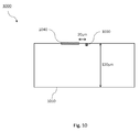
- Fig. 10 illustrates a front scheme of the structure of a semiconductor laser device according to one embodiment of the disclosure, where a cross section of the semiconductor laser perpendicular to the laser waveguide is shown.
- the semiconductor laser device 1000 comprises a semiconductor material 1010, which may be for example a Indium Phosphide (InP) chip, a laser waveguide 1030 for generating or modulating an optical signal in response to a first drive current that is applied thereto during transmission periods, e.g. data bursts, and a heating region or a parallel heating device 1040, which may be for example a Nickel-Chromium (NiCr) resisting stripe.
- the heating region or the parallel heating device 1040 may be located on the top of the semiconductor material 1010, aside the laser waveguide 1030.
- the NiCr resistance is controlled by injecting electrical current or applying a voltage between two electrodes positioned at the extremities.
- the heating region or the parallel heating device 1040 serving as a heater is e.g. 20 ⁇ m away from the laser waveguide 1030.
- the electrical current injected to the heater 1040 corresponding to a second drive current may be obtained from the voltage applied to the heater 1040.
- the heater 1040 could be brought even closer to the laser waveguide 1030.
- the laser is turned on during data bursts, or when a voltage is applied to the heater 1040 at the end of the data burst, heat is generated locally around the laser waveguide 1030. Owing to the proximity between the heater 1040 and the laser waveguide 1030 (e.g. ⁇ 20 ⁇ m) compared to the InP chip thickness (e.g. ⁇ 120 ⁇ m), temperature at the bottom of the InP chip remains almost constant when switching from laser self-heating to heater operation and there is no variation of heat flux towards the InP chip bottom.
- Fig.4 and Fig. 5 schematically illustrate examples of laser assemblies (laser modules) 400, 500 according to embodiments of the disclosure, which may comprise each of the above-described semiconductor lasers.
- Both laser assemblies 400, 500 comprise a semiconductor laser 100, 200 as described above, and a drive circuit (laser driver) 420 for driving the first semiconductor region 130 of the semiconductor laser 100, 200, i.e. for generating the first drive current for the semiconductor laser 100, 200.
- the laser assembly 400, 500 receives an input signal from a logic circuit (e.g. a PON logic) 430 that is fed to the drive circuit 420.
- the laser assemblies 400, 500 further comprise a pulse generation circuit (pulse generator) 460.
- the laser assembly 500 in Fig. 5 further comprises an averaging circuit (averager) 470.
- the input signal generated by the logic circuit 430 may comprise a burst enable signal (a sequence of rectangular pulses, each rectangular pulse corresponding to a respective transmission period) indicating transmission periods of the semiconductor laser 100, 200 and biasing the semiconductor laser 100, 200 at its operation point, and a data signal indicating actual data to be transmitted by means of optical emission by the semiconductor laser 100, 200.
- the burst enable signal and the data signal are fed to the drive circuit 420.
- the drive circuit 420 generates the first drive current that is applied to the first semiconductor region 130 of the semiconductor laser 100, 200 on the basis of the input signal, i.e. on the basis of the burst enable signal and/or the data signal.
- the first drive current is zero during the IBGs, i.e. a drive current is not applied to the first semiconductor region 130 during the IBGs.
- the burst enable signal is additionally fed to the pulse generation circuit 460.
- the pulse generation circuit 460 generates, on the basis of the burst enable signal, the second drive current that is applied to the heating region, e.g. the second semiconductor region 140 and, if present, also to the another heating region, e.g. the third semiconductor region 150.
- the second drive current may be generated to be proportional to the inverted burst enable signal, or to correspond to a dummy sequence during the IBGs (i.e. when the burst enable signal is zero).
- the second drive current is zero during the transmission periods, i.e. a drive current is not applied to the second semiconductor region 140 (and the third semiconductor region 150) during transmission periods.
- the data signal is fed to the averaging circuit 470.
- the averaging circuit 470 may be implemented by a suitable low pass filter.
- the averaging circuit 470 generates an envelope of the data signal e.g. by averaging the data signal.
- the generated envelope is fed to the pulse generation circuit 460.
- the pulse generation circuit 460 generates, on the basis of the envelope of the data signal, the second drive current that is applied to the second semiconductor region 140 and, if present, also to the third semiconductor region 150.
- the second drive current may be generated to be proportional to the inverted envelope of the data signal, or to correspond to a dummy sequence during the IBGs (i.e. when the envelope of the data signal is zero).
- the drive circuit 420 and the pulse generation circuit 460 in the case of Fig. 4 and the drive circuit 420, the pulse generation circuit 460, and the averaging circuit 470 in the case of Fig. 5 may be said to form a drive unit for driving the semiconductor laser 100, 200.
- the drive unit generates the first and second drive currents.
- the drive unit further applies the first drive current to the first semiconductor region 130, and the second drive current to the second semiconductor region 140 (and the third semiconductor region 150, if present).
- the (non-zero) first drive current is applied to the first semiconductor region 130 during the transmission periods, and the (non-zero) second drive current is applied to the second semiconductor region 140 (and the third semiconductor region 150, if present) during the IBGs.
- Fig. 6 is an exemplary schematic timing diagram of time-dependent quantities related to operation of the laser assemblies 400 and 500 illustrated in Fig. 4 and Fig. 5 .
- the topmost diagram 610 indicates an example of the first drive current output by the drive circuit 420 and injected to the first semiconductor region 130 of the semiconductor laser 100, 200, and the output optical power of the semiconductor laser 100, 200.
- the first drive current and the output optical power are illustrated to have qualitatively the same variation in time.
- the second diagram 620 from the top indicates an example of the laser temperature within the first semiconductor region 130 and the emission wavelength of the optical signal output by the semiconductor laser 100, 200 during data bursts, both for a case in which the self-heating mitigation technique according to the disclosure is not applied.
- the laser temperature and the emission wavelength are schematically illustrated to have qualitatively the same variation in time. Needless to say, the emission wavelength is understood to be zero during intervals between data bursts.
- the third diagram 630 from the top indicates an example of the second drive current that is applied to the heating region, e.g. the second semiconductor region 140 (and the another heating region, e.g. the third semiconductor region 150, if present).
- the fourth diagram 640 from the top indicates an example of the temperature of the first semiconductor region 130 induced by heat generated in the second semiconductor region 140 (and the third semiconductor region 150, if present), ignoring any heat generated by the first semiconductor region 130 during transmission periods.
- the lowermost diagram 650 indicates an example of the net temperature of the first semiconductor region 130 and the emission wavelength of the optical signal output by the semiconductor laser 100, 200 during data bursts for the case in which the self-heating mitigation technique according to the disclosure is applied. Also the net temperature and the emission wavelength are schematically illustrated to have qualitatively the same variation in time.
- the laser temperature rises during data bursts, and the emission wavelength of the optical signal increases proportionally to the temperature increase.
- the second drive current has a constant level during the IBGs, and is zero during the transmission periods. Further, the heat transferred to the first semiconductor region 130 during the IBGs prevents a cooling off of the first semiconductor region 130 during the IBGs and keeps constant the temperature of the first semiconductor region 130 across periods of transmission and IBGs. Accordingly, if the self-heating mitigation technique according to the disclosure is applied, the emission wavelength of the optical signal is substantially constant over time during data bursts.
- the transient heat generation occurs in the electrical absorption modulator (EAM) as well as in the gain section, if the laser section is activated only during bursts.
- EML externally modulated laser
- the laser section is activated only during bursts.
- an additional on-chip SOA e.g. for power levelling or for boosting the output power, then also this element will generate heat bursts on the chip.
- additional dummy heating sections will help keep the temperature of the active stripe constant over time, thus preventing wavelength drifts.
- a dummy section can be specially designed to compensate for the net effect of all the transient heat generation in the different sections of the semiconductor laser. This requires thermal modelling of the laser structure.
- a dummy section used as a heating region can be for example a semiconductor region, a parallel fake waveguide, or a metallic heater made of resistive material. If a semiconductor region is chosen to be the dummy heating section, an alternate and possibly simpler approach is to just copy the respective heat generating sections of the laser structure and place them as dummy elements next to the original elements and drive them during the IBGs with appropriate electrical currents, as discussed above.
- Fig. 3 schematically illustrates another example of a semiconductor laser 300 according to embodiments of the disclosure, which is an EML.
- the semiconductor laser 300 comprises a laser section (left-hand side) and an external modulator section (right-hand side).
- the externally modulated optical signal is emitted from the semiconductor laser 300 in a direction pointing to the right in Fig. 3 .
- the laser section comprises a first semiconductor region 330 which is an active section for generating an optical signal as well as second and third semiconductor regions 340, 350, which are dummy sections used as heating regions. Either one of the second and third semiconductor regions 340, 350 may be omitted.
- the external modulator section comprises a first semiconductor region 335, which is an active section for modulating the optical signal generated by the first semiconductor region 330 of the laser section, as well as second and third semiconductor regions 345, 355, which are dummy sections. Either one of the second or third semiconductor regions 345, 355 of the external modulation section may be omitted.
- the first semiconductor region 330 of the laser section is driven by a first drive current for the laser section, and the second and third semiconductor regions 340, 350 of the laser section are driven by a second drive current for the laser section.
- the first semiconductor region 335 of the external modulator section is driven by a first drive current for the external modulator section, and the second and third semiconductor regions 345, 355 of the external modulator section are driven by a second drive current for the external modulator section. It is understood that any statements made earlier with respect to the second and third semiconductor regions and respective drive currents also apply to the configuration illustrated in Fig. 3 .
- an amount of heat generated by the external modulator section can be kept constant across transmission periods and IBGs. Accordingly, an amount of heat transferred to the laser section is constant over time and will not cause a drift of the emission wavelength of the first semiconductor region of the laser section. In other words, operating the external modulator section in burst mode does not cause a drift of the emission wavelength of the laser section.
- one or more dummy regions may be provided as heating regions for any other active region of a semiconductor laser that generates heat due to current injection, such as the active region of an SOA.
- any other active region of a semiconductor laser that generates heat due to current injection such as the active region of an SOA.
- Fig. 7 and Fig. 8 schematically illustrate further examples of laser assemblies (laser modules) 700, 800 according to embodiments of the disclosure, which may comprise the semiconductor laser 300 described with reference to Fig. 3 .
- laser assemblies laser modules 700, 800 according to embodiments of the disclosure, which may comprise the semiconductor laser 300 described with reference to Fig. 3 .
- statements analogous to those made earlier with respect to corresponding components of the respective laser assemblies in Fig. 4 and Fig. 5 are understood to apply also here.
- Both laser assemblies 700, 800 comprise a semiconductor laser 300 as described above, and a drive circuit (laser driver) 720 for driving the first semiconductor regions 330, 335 of the laser section and the external modulator section of the semiconductor laser 300, i.e. for generating the first drive current for the laser section and the first drive current for the external modulator section of the semiconductor laser 300.
- the laser assembly 700, 800 receives an input signal from a logic circuit (e.g. a PON logic) 730 that is fed to the drive circuit 720.
- the laser assemblies 700, 800 further comprise a pulse generation circuit (pulse generator) 760.
- the laser assembly 800 in Fig. 8 further comprises an averaging circuit (averager) 770.
- the input signal generated by the logic circuit 730 corresponds to that described above with reference to Fig. 4 and Fig. 5 and may comprise a burst enable signal and a data signal.
- the burst enable signal and the data signal are fed to the drive circuit 720.
- the drive circuit 720 generates the first drive current for the laser section that is applied to the first semiconductor region 330 of the laser section of the semiconductor laser 300 on the basis of the input signal, i.e. on the basis of the burst enable signal and/or the data signal.
- the drive circuit 720 further generates the first drive current for the external modulator section that is applied to the first semiconductor region 335 of the external modulator section of the semiconductor laser 300 on the basis of the input signal, i.e. on the basis of the burst enable signal and/or the data signal.
- the burst enable signal is additionally fed to the pulse generation circuit 760.
- the pulse generation circuit 760 generates, on the basis of the burst enable signal, the second drive current for the laser section that is applied to the heating region, e.g. the second semiconductor region 340 and, if present, also to the another heating region, e.g. the third semiconductor region 350 of the laser section of the semiconductor laser 300. Further, the pulse generation circuit 760 generates, on the basis of the burst enable signal, the second drive current for the external modulator section that is applied to the heating region, e.g. the second semiconductor region 345 and, if present, also to the another heating region, e.g. the third semiconductor region 355 of the external modulator section of the semiconductor laser 300.
- the data signal is fed to the averaging circuit 770.
- the averaging circuit 770 generates an envelope of the data signal e.g. by averaging the data signal.
- the generated envelope is fed to the pulse generation circuit 760.
- the pulse generation circuit 760 generates, on the basis of the envelope of the data signal, the second drive current for the laser section of the semiconductor laser 300 that is applied to the heating region, e.g. the second semiconductor region 340 and, if present, also to the another heating region, e.g. the third semiconductor region 350 of the laser section of the semiconductor laser 300.
- the pulse generation circuit 760 further generates, on the basis of the envelope of the data signal, the second drive current for the external modulator section of the semiconductor laser 300 that is applied to the heating region, e.g. the second semiconductor region 345 and, if present, also to the another heating region, e.g. the third semiconductor region 355 of the external modulator section of the semiconductor laser 300.
- the drive circuit 720 and the pulse generation circuit 760 in the case of Fig. 7 and the drive circuit 720, the pulse generation circuit 760, and the averaging circuit 770 in the case of Fig. 8 may be said to form a drive unit for driving the semiconductor laser 300.
- the drive unit generates the first and second drive currents.
- the drive unit further applies the first drive currents to respective first semiconductor regions 330, 335, and applies the second drive currents to respective second semiconductor regions 340, 345 (and respective third semiconductor regions 350, 355, if present).
- Fig. 9 is a schematic timing diagram of time-dependent quantities related to operation of the laser assemblies illustrated in Fig. 7 and Fig. 8 .
- the topmost diagrams 910, 915 indicate an example of the first drive current for the laser section of the semiconductor laser output by the drive circuit 720 and injected to the first semiconductor region 330 of the laser section of the semiconductor laser 300 (left diagram) and an example of the first drive current for the external modulator section of the semiconductor laser output by the drive circuit 720 and injected to the first semiconductor region 335 of the external modulator section of the semiconductor laser 300 and the output optical power of the semiconductor laser 300 (right diagram).
- the first drive current for the external modulator section and the output optical power are illustrated to have qualitatively the same variation in time.
- the second diagram 920 from the top indicates an example of the laser temperature within the first semiconductor region 330 of the laser section and the emission wavelength of the optical signal output by the semiconductor laser 300 during data bursts, both for a case in which the self-heating mitigation technique according to the disclosure is not applied. Also the laser temperature and the emission wavelength are schematically illustrated to have qualitatively the same variation in time. Needless to say, the emission wavelength is understood to be zero during intervals between data bursts.
- the third diagrams 930, 935 from the top indicate an example of the second drive current for the laser section that is applied to the heating region, e.g. the second semiconductor region 340 (and the another heating region, e.g.
- the fourth diagram 940 from the top indicates an example of the temperature of the first semiconductor region 330 of the laser section, ignoring any heat generated by the first semiconductor regions 330, 335 during transmission periods.
- the lowermost diagram 950 indicates an example of the net temperature of the first semiconductor region 330 of the semiconductor laser 300 and the emission wavelength of the optical signal output by the semiconductor laser 300 during data bursts for the case in which the self-heating mitigation technique according to the disclosure is applied. Also the net temperature and the emission wavelength are schematically illustrated to have qualitatively the same variation in time.
- the laser section is driven only during transmission periods.
- the laser section could be driven continuously. This case is not reflected in the remaining diagrams.
- the laser temperature rises during data bursts, and the emission wavelength increases proportionally to the temperature increase.
- the second drive currents have a constant level during the IBGs, and are zero during the transmission periods.
- the heat that is transferred to the first semiconductor regions 330, 335 during the IBGs prevents a cooling off of the first semiconductor regions 330, 335 during the IBGs and keeps constant the temperature of the first semiconductor regions 330, 335 across periods of transmission and IBGs. Accordingly, if the self-heating mitigation technique according to the disclosure is applied, there is no cooling off of the first semiconductor regions 330, 335 between data bursts and the emission wavelength of the optical signal is substantially constant over time during data bursts.
- FIG. 11 schematically illustrates a set-up to demonstrate the effectiveness of the semiconductor laser device 1000 in Fig. 10 according to one embodiment of the disclosure.
- a laser module (not shown) similar to laser assemblies 400, 500 comprises a directly modulated laser (DML) with a heater 1100.
- Current sequences 1130 of 1ms are applied to the laser waveguide 1030, while opposite voltage steps 1140 are synchronously applied to the heater 1040.
- the DML output is then transmitted through a 0.25nm ( ⁇ 30GHz) narrow-band filter 1110. By positioning a filter edge on the laser emission wavelength, wavelength modulation is transferred into amplitude modulation.
- the output signal 1150 is then visualized on an oscilloscope 1120.
- Fig. 12 shows the resulting signals on the oscilloscope 1120 in Fig. 11 for increasing heater counter-modulation voltages, i.e. operating a heater 1040 with 0V (no heating) during laser on-states and with voltages ranging from 0 to 3V during laser off-states.
- the result of Fig. 12(a) corresponds to laser modulation current between 60 and 100mA for a sequence period of 1ms.
- the result of Fig. 12(b) corresponds to laser modulation current between 0 and 80mA for a sequence period of 40ms.
- the signal slowly shifts during the laser on-state due to laser self-heating 1200, 1220, indicating that wavelength is not stabilized, even after 20ms.
- the heater voltage during laser off-states is increased, the signal variation decreases until becoming stable, which corresponds to the heater voltage exactly compensating for laser self-heating.
- This heater voltage depends on laser modulation currents. For laser modulation current between 60 and 100mA, the optimum heater counter-modulation is 0V/2.15V, represented by the curve 1210, while for laser modulation current between 0 and 80mA, the optimum heater counter-modulation is 0V/2.6V, represented by the curve 1230. In that situation, the wavelength is clearly stabilized after only a few ⁇ s.
Abstract
Description
- This application relates to laser assemblies (laser modules) comprising semiconductor lasers, particularly for use in burst-mode operation, and to methods for driving semiconductor lasers, particularly in burst-mode operation. The application relates to both laser modules comprising directly modulated lasers (DMLs) and externally modulated lasers (EMLs).
- Directly tunable lasers, such as e.g. distributed feedback (DFB) lasers and to some degree also other laser types such as EMLs suffer from self-heating induced wavelength drifts during burst-mode operation. In signal processing, this drift results in signal degradations when signals generated by these lasers are passed through narrowband wavelength filters at the receive side, e.g. at the optical line termination (OLT) in a time and wavelength division multiplexed passive optical network (TWDM-PON). This leads to unacceptable transmission errors and instabilities in wavelength stabilization schemes based on e.g. received signal strength indication (RSSI) measurements. Thus, without self-heating mitigation, these lasers are not useable in networks with filter widths in the order of 50 GHz or less.
- A number of generic mitigation techniques that are applicable to semiconductor lasers have been proposed so far, e.g. applying accelerated heating, elevated subthreshold bias current or operation at low output powers. However, in order for these mitigation techniques to be efficient, the respective semiconductor laser would need to be driven in a non-optimal point of operation, resulting in system penalties due to e.g. lower power or degraded eye openings.
- Thus, there is a need for improved self-heating mitigation techniques applicable to semiconductor lasers.
- In view of this need, the present document proposes a laser assembly and a method of driving a semiconductor laser having the features of the respective independent claims.
- An aspect of the disclosure relates to a laser assembly (a laser module). The laser assembly may comprise a semiconductor laser and a drive unit for driving the semiconductor laser. The semiconductor laser may comprise a first semiconductor region for generating or modulating an optical signal in response to a first drive current that is injected (applied) to the first semiconductor region and a heating region that is arranged in proximity to the first semiconductor region and electrically insulated from the first semiconductor region. The drive unit may be configured to generate the first drive current and a second drive current, inject (apply) the first drive current to the first semiconductor region during respective transmission periods (data bursts) of the semiconductor laser, and inject (apply) the second drive current to the heating region in intervals between successive transmission periods (inter burst gaps, IBGs). The heating region may be configured to have characteristics of heat generation that are matched to those of the first semiconductor region, e.g. the heating region and the first semiconductor region may have substantially the same characteristics of heat generation. The heating region may be for example a second semiconductor region, a parallel waveguide or a metallic heater made of resistive material. The heating region may be configured to not emit any light when injected with the second drive current (i.e. may be optically inactive, e.g. due to including deep electron traps or being appropriately doped otherwise), or to not emit any light that would be coupled into an optical fiber that is attachable to the semiconductor laser to receive the optical signal generated or modulated by the first semiconductor region. This may require optically insulating the heating region from the first semiconductor region. In consequence, the first semiconductor region may be referred to as an active region, whereas the heating region may be referred to as a passive region, or dummy region.
- Configured as above, heat is generated in the heating region during the IBGs and transferred to the first semiconductor region. Thereby, a temperature drop in the first semiconductor region during IBGs may be avoided, or at least mitigated. A difference between the temperature of the first semiconductor region at the beginning of each transmission period and a temperature of the first semiconductor region at the end of the respective transmission period thus vanishes or is at least reduced. Since the drift in emission wavelength depends on the rise of temperature of the first semiconductor region between the beginning of an IBG and the end of the respective IBG, the drift in emission wavelength is altogether avoided or at least mitigated in the above laser assembly. This makes the above the laser assembly a perfect candidate for use e.g. in TWDM-PONs with filter widths of 50 GHz or less, such as a NG-PON2 network.
- In embodiments, the first semiconductor region may be one of an active region of a laser section of a semiconductor laser (e.g. a DML or an EML), an active region of an external modulator section of a semiconductor laser (e.g. an EML), or an active region of a semiconductor optical amplifier (SOA). Further, the first semiconductor region may be an active region of any other section of a semiconductor laser that generates heat due to current injection.
- In embodiments, the heating region may have a high frequency response (time response) substantially identical (or at least, similar) to a high frequency response of the first semiconductor region. Likewise, circuitry for driving the heating region (including wiring and wire bonding; e.g. a circuit path) may have a high frequency response (time response) substantially identical (or at least, similar) to a high frequency response of circuitry for driving the first semiconductor region, i.e. both may be equally (or at least similarly) suitable for high frequency operation.
- In embodiments, the heating region may have substantially the same shape and material composition (e.g. the same doping profile) as the first semiconductor region.
- Thereby, if a second semiconductor region has been chosen to be the heating region, the second semiconductor region with appropriate characteristics of heat generation may be provided in a particularly simple manner, without extensive simulations of heat generation. Moreover, manufacturing of the semiconductor laser is particularly simple since merely the steps that lead to creation of the first semiconductor region need to be repeated.
- In embodiments, the heating region may be arranged relative to the first semiconductor region so that heat generated by the heating region may diffuse to the first semiconductor region and heat up the first semiconductor region. Further, the characteristics of heat generation of the heating region may be chosen in such a manner that a heat transfer from the heating region to the first semiconductor region during the intervals between successive transmission periods is dimensioned so that a temperature of the first semiconductor region during the intervals between successive periods of transmission is kept at the same level as during the transmission periods. This translates into the requirement that heat losses of the first semiconductor region during intervals between transmission periods are compensated for by heat transfer from the heating region to the first semiconductor region. More specifically, the second drive current and the characteristics of heat generation of the heating region may be chosen to attain this goal. Thereby, the temperature of the first semiconductor region may be kept substantially constant across the transmission periods and the intervals there between.
- Configured as above, a drift of the emission wavelength is effectively removed.
- In embodiments, the semiconductor laser may further comprise another heating region that is electrically insulated from the first semiconductor region and arranged in proximity to the first semiconductor region such that the first semiconductor region is sandwiched between the heating region and the another heating region. The drive unit may be further configured to apply a third drive current to said another heating region in the intervals between successive transmission periods. The third drive current may be identical to the second drive current. Said another heating region may be configured to have characteristics of heat generation that are matched to those of the first semiconductor region. Said another heating region may be for example a third semiconductor region, another parallel waveguide or another metallic heater made of resistive material. Said another heating region may be configured to not emit any light when injected with the drive current (i.e. may be optically inactive, e.g. due to including deep electron traps or being appropriately doped otherwise), or to not emit any light that would be coupled into an optical fiber that is attachable to the semiconductor laser to receive the optical signal generated or modulated by the first semiconductor region. This may require optically insulating said another heating region from the first semiconductor region. In consequence, also said another heating region may be referred to as a passive region, or dummy region.
- By providing two passive heating regions sandwiching the first semiconductor region, the first semiconductor region may be more uniformly heated and compensation of the drift of the emission wavelength may be further improved.
- In embodiments, said another heating region may be arranged relative to the first semiconductor region so that heat generated by said another heating region may diffuse to the first semiconductor region and heat up the first semiconductor region. Further, the characteristics of heat generation of the heating region and the another heating region may be chosen in such a manner that a heat transfer from the heating region and the another heating region to the first semiconductor region during the intervals between successive transmission periods is dimensioned such that a temperature of the first semiconductor region during the intervals between successive periods of transmission is kept at the same level as during the transmission periods. This translates into the requirement that heat losses of the first semiconductor region during intervals between transmission periods are compensated for by heat transfer from the heating region and the another heating region to the first semiconductor region. More specifically, the second and third drive currents and the characteristics of heat generation of the heating region and said another heating region may be chosen to attain this goal. Thereby, the temperature of the first semiconductor region may be kept substantially constant across the transmission periods and the intervals there between.
- In embodiments, said another heating region may have a high frequency response (time response) substantially identical (or at least, similar) to a high frequency response of the first semiconductor region. Likewise, circuitry for driving said another heating region (including wiring and wire bonding; e.g. a circuit path) may have a high frequency response (time response) substantially identical (or at least, similar) to a high frequency response of circuitry for driving the first semiconductor region, i.e. both may be equally (or at least similarly) suitable for high frequency operation.
- In embodiments, the drive unit is configured to generate the second drive current such that the second drive current is different from zero during at least a portion of each of the intervals between successive transmission periods. For example, the second drive current may relate to a sequence of current pulses that each extend over the full length of a respective interval between successive transmission periods. The same may apply to the third drive current. For example, the third drive current may be identical to the second drive current.
- In embodiments, the drive unit may be configured to generate the first drive current on the basis of an input signal comprising a data signal indicative of data to be transmitted by means of the optical signal. The drive unit may be further configured to generate the second drive current on the basis of the first drive current or the input signal.
- Thereby, synchronicity between the second drive current and the IBGs can be ensured. Moreover, the second drive current can be specifically adapted to compensate for the heat loss of the first semiconductor region during the IBGs. The reason is that said heat loss depends, among others, on the temperature of the first semiconductor region at the end of the respective transmission period, and said temperature in turn depends on the data transmitted during the respective transmission period, i.e. on the input data.
- Another aspect of the disclosure relates to a method of driving a semiconductor laser. The semiconductor laser may comprise a first semiconductor region for generating or modulating an optical signal in response to a first drive current that is applied to the first semiconductor region, and a heating region that is arranged in proximity to the first semiconductor region and electrically insulated from the first semiconductor region. The heating region may be configured to have characteristics of heat generation that are matched to those of the first semiconductor region, e.g. the heating region and the first semiconductor region may have substantially the same characteristics of heat generation. The heating region may be for example a second semiconductor region, a parallel waveguide or a metallic heater made of resistive material. The heating region may be configured to not emit any light when injected with the second drive current (i.e. may be optically inactive, e.g. due to including deep electron traps or being appropriately doped otherwise), or to not emit any light that would be coupled into an optical fiber attachable to the semiconductor laser to receive the optical signal generated or modulated by the first semiconductor region. This may require optically insulating the heating region from the first semiconductor region. In consequence, the first semiconductor region may be referred to as an active region, whereas the heating region may be referred to as a passive region, or dummy region. If a second semiconductor region has been chosen to be the heating region, each semiconductor region may correspond to a semiconductor layer or part of a semiconductor layer. The method may comprise applying the first drive current to the first semiconductor region during respective transmission periods of the semiconductor laser. The method may further comprise applying a second drive current to the heating region in intervals between successive transmission periods.
- In embodiments, the semiconductor laser may further comprise another heating region that is electrically insulated from the first semiconductor region and arranged in proximity to the first semiconductor region such that the first semiconductor region is sandwiched between the heating region and the another heating region. The method may further comprise applying a third drive current to the another heating region in the intervals between successive transmission periods. The third drive current may be identical to the second drive current. The another heating region may be configured to have characteristics of heat generation that are matched to those of the first semiconductor region. The another heating region may be for example a third semiconductor region, another parallel waveguide or another metallic heater made of resistive material. The another heating region may be configured to not emit any light when injected with the drive current (i.e. may be optically inactive, e.g. due to including deep electron traps or being appropriately doped otherwise), or to not emit any light that would be coupled into an optical fiber that is attachable to the semiconductor laser to receive the optical signal generated or modulated by the first semiconductor region. This may require optically insulating the another heating region from the first semiconductor region. In consequence, also the another heating region may be referred to as a passive region, or dummy region.
- In embodiments, the second drive current may be different from zero during at least a portion of each of the intervals between successive transmission periods. For example, the second drive current may relate to a sequence of current pulses that each extend over the full length of a respective interval between successive transmission periods. The same may apply to the third drive current. For example, the third drive current may be identical to the second drive current.
- In embodiments, the method may further comprise generating the first drive current on the basis of an input signal comprising a data signal indicative of data to be transmitted by means of the optical signal, and generating the second drive current on the basis of the first drive current or the input signal.
- It will be appreciated that method steps and apparatus features may be interchanged in many ways. In particular, the details of the disclosed apparatus can be implemented as a method, as the skilled person will appreciate.
- Embodiments of the disclosure are explained below in an exemplary manner with reference to the accompanying drawings, wherein
-
Fig. 1 schematically illustrates an example of a semiconductor laser according to embodiments of the disclosure; -
Fig. 2 schematically illustrates another example of a semiconductor laser according to embodiments of the disclosure; -
Fig. 3 schematically illustrates another example of a semiconductor laser according to embodiments of the disclosure; -
Fig. 4 andFig. 5 schematically illustrate examples of laser assemblies according to embodiments of the disclosure; -
Fig. 6 is a schematic timing diagram of time-dependent quantities related to operation of the laser assemblies illustrated inFig. 4 andFig. 5 ; -
Fig. 7 andFig. 8 schematically illustrate further examples of laser assemblies according to embodiments of the disclosure; -
Fig. 9 is a schematic timing diagram of time-dependent quantities related to operation of the laser assemblies illustrated inFig. 7 andFig. 8 ; -
Fig. 10 schematically illustrates a facet of a semiconductor laser device according to one embodiment of the disclosure; -
Fig. 11 is a schematic set-up to demonstrate the effectiveness of the semiconductor laser device illustrated inFig. 10 according to one embodiment of the disclosure; and -
Fig. 12 is a schematic timing diagram of time-dependent quantities related to the effectiveness of the semiconductor laser device illustrated inFig. 10 using the demonstrating set-up ofFig. 11 according to one embodiment of the disclosure. - The basic idea in this disclosure consists in maintaining the temperature constant in the area of the laser waveguide, whether the laser is turned on or off. During data bursts, laser temperature is increased by ΔT due to self-heating. When the laser is turned off at the end of a data burst, a heating region or a heating parallel device positioned along the laser waveguide is synchronously heated in order to locally heat the laser by the same ΔT. Therefore, the laser is always at a temperature equal to thermoelectric cooler controller (TEC) temperature + ΔT. ΔT is obtained by the laser self-heating during data bursts, and by the heating region or the parallel heating device between data bursts. Due to the proximity between the laser waveguide and the heating region or parallel heating device, the laser heating by the heating device or the heating region is almost instantaneous. Thus, the temperature is kept constant and there is no time variation of the flux of heat towards the submount and Peltier control. The heating region or the parallel heating device can be for example a semiconductor region, a parallel fake waveguide, or a metallic heater made of resistive material, e.g. Chromium (Cr), Platinum (Pt) or others.
- In a directly modulated laser, such as a DFB laser, the injection current (first drive current) modulates the gain in the DFB section (active section/stripe, gain section/stripe, or first semiconductor region) of the laser. Almost the entire electrical energy is converted into heat, leading to the observed wavelength-drift over time during short data bursts. To prevent occurrence of these wavelength transients during data bursts (during transmission periods) it is proposed to implement an additional dummy section (a heating region) close to the active section of the laser which is electrically driven during the gaps between data bursts (inter-burst-gaps, IGBs, or intervals between successive transmission periods), thus generating heat even when no optical signals are generated. For instance, a dummy stripe may be provided in parallel to the active stripe.
- Then, due to this constant generation of heat in the semiconductor laser during both data bursts and IBGs there will be no more variation of the emission wavelength during the generation of optical signals during data bursts.
- The heat (and correspondingly, the temperature) in the active section of the laser should remain constant over time, irrespective of whether or not optical data is generated. In order to accomplish this, the dummy stripe should be positioned (arranged) close to the active stripe (typically only a few micrometers apart) and preferably have a shape and material composition very similar (e.g. substantially identical) to the active stripe.
- However, care must be taken not to generate additional light during the IBGs, or alternatively, to prevent such light that is generated during the IBGs from being coupled into the optical fiber that receives the optical signal output from the semiconductor laser. This may be ensured by an appropriate design of the laser structure and optionally by an appropriate treatment of the dummy section, e.g. by introducing deep level electronic traps into the dummy section for reducing the radiative electron-hole recombination rate or by otherwise doping the dummy section to prevent emission of light.
-
Fig. 1 schematically illustrates an example of asemiconductor laser 100 according to embodiments of the disclosure. Thesemiconductor laser 100 comprises asemiconductor material first semiconductor region 130 during transmission periods (but not during IBGs), and a second semiconductor region (dummy region, dummy stripe) 140 as heating region. Thesecond semiconductor region 140 may be arranged in proximity to the first semiconductor region such that heat generated in thesecond semiconductor region 140 may diffuse to thefirst semiconductor region 130. Thesecond semiconductor region 140 may be arranged in parallel to thefirst semiconductor region 130. Further, thesecond semiconductor region 140 may be electrically insulated from thefirst semiconductor region 130. This may be achieved e.g. by providing an appropriate doping profile between thefirst semiconductor region 130 and the second semiconductor region 140 (i.e. by providing an insulation layer), or by providing an air-filled gap between thefirst semiconductor region 130 and thesecond semiconductor region 140. Moreover, thesecond semiconductor region 140 may be optically inactive and/or be optically insulated from thefirst semiconductor region 130, as indicated above. - The above reference to a directly modulated laser, such as a DFB laser, is understood to indicate an example, without intended limitation of the present disclosure. In general, the first semiconductor region may be one of an active region of a laser section of a semiconductor laser (e.g. a DML or an EML), an active region of an external modulator section of a semiconductor laser (e.g. an EML), or an active region of an SOA. Further, the first semiconductor region may be an active region of any other section of a semiconductor laser that generates heat due to current injection.
- The
second semiconductor region 140 may be electrically driven by a second drive current during the IGBs, but not during the transmission periods. The second drive current may relate e.g. to a single current pulse lasting over the entire duration of the IBG or to a sequence of current pulses representing a sequence of dummy data (e.g. a "1010" sequence) during the IBG. In the former case thesecond semiconductor region 140 needs to handle lower electrical bandwidths (typically few MHz) as compared to the latter case (few GHz) and may therefore be the preferred case. Notably, there is freedom in the choice of the signal structure of the second drive current, as long as requirements described further below are met. - The
second semiconductor region 140 may have characteristics of heat generation (e.g. indicative of a time dependence of heat generation and an amount of heat generation in dependence on an injected drive current) matched to those of thefirst semiconductor region 130. For instance, the characteristics of heat generation of the second semiconductor region may be substantially identical to those of thefirst semiconductor region 130. This may be achieved by providing the second semiconductor region with the same shape and material composition (e.g. same doping profile) as thefirst semiconductor region 130. - In most general terms, the requirements for the structure of the second drive current and for the characteristics of heat generation of the
second semiconductor region 140 are that the amount of heat generated by thesecond semiconductor region 140 driven by the second drive current and arriving in thefirst semiconductor region 130 during the IGBs must be identical to the heat generated by thefirst semiconductor region 130 during the real data bursts. Said heat generated by thesecond semiconductor region 140 depends on both the second drive current and the characteristics of heat generation of thesecond semiconductor region 140. It may be further required to also take into account time constants and losses in the heat transfer between thesecond semiconductor region 140 and thefirst semiconductor region 130, which may depend on the relative arrangement of the first andsecond semiconductor regions - In other words, the characteristics of heat generation of the
second semiconductor region 140 and the second drive current need to be chosen in such a manner that a heat transfer from thesecond semiconductor region 140 to thefirst semiconductor region 130 during the IBGs is dimensioned so that a temperature of thefirst semiconductor region 130 during the IBGs is kept at the same level as during the transmission periods, i.e. so that the temperature of thefirst semiconductor region 130 is kept substantially constant across transmission periods and IBGs during operation in burst mode. - In embodiments, two dummy sections may be implemented, one on either side of the active stripe. This situation is illustrated in
Fig. 2 . Thesemiconductor laser 200 illustrated inFig. 2 comprises the regions described above in connection withFig. 1 , and additionally a third semiconductor region (dummy region, dummy section, dummy stripe) 150 as another heating region. The second andthird semiconductor regions first semiconductor region 130. Thethird semiconductor region 150 may be arranged in proximity to the first semiconductor region such that heat generated in thethird semiconductor region 150 may diffuse to thefirst semiconductor region 130. Thethird semiconductor region 150 may be arranged in parallel to thefirst semiconductor region 130. Further, thethird semiconductor region 150 may be electrically insulated from thefirst semiconductor region 130. This may be achieved e.g. by providing an appropriate doping profile between thefirst semiconductor region 130 and the third semiconductor region 150 (i.e. by providing an insulation layer), or by providing an air-filled gap between thefirst semiconductor region 130 and thethird semiconductor region 150. Moreover, thethird semiconductor region 150 may be optically inactive and/or be optically insulated from thefirst semiconductor region 130. This may be achieved in the same manner as described above in connection with thesecond semiconductor region 140. - The
third semiconductor region 150 may be electrically driven by a third drive current during the IGBs, but not during the transmission periods. Similar to the second drive current, the third drive current may relate e.g. to a single current pulse lasting over the entire duration of the IBG or to a sequence of current pulses representing a sequence of dummy data (e.g. a "1010" sequence) during the IBG. For simplicity, the third drive current may be identical to the second drive current. - The
third semiconductor region 150 may have characteristics of heat generation (e.g. indicative of a time dependence of heat generation and an amount of heat generation in dependence on an injected drive current) matched to those of thefirst semiconductor region 130. For instance, the characteristics of heat generation of thethird semiconductor region 150 may be substantially identical to those of thefirst semiconductor region 130. - In any case, the characteristics of heat generation of the
third semiconductor region 150 and the third drive current need to be chosen in such a manner that a heat transfer from thethird semiconductor region 150 to thefirst semiconductor region 130 during the IBGs is dimensioned so that a temperature of thefirst semiconductor region 130 during the IBGs is kept at the same level as during the transmission periods. More precisely, the characteristics of heat generation of the second andthird semiconductor regions third semiconductor regions first semiconductor region 130 during the IBGs is dimensioned so that a temperature of thefirst semiconductor region 130 during the IBGs is kept at the same level as during the transmission periods. -
Fig. 10 illustrates a front scheme of the structure of a semiconductor laser device according to one embodiment of the disclosure, where a cross section of the semiconductor laser perpendicular to the laser waveguide is shown. Thesemiconductor laser device 1000 comprises asemiconductor material 1010, which may be for example a Indium Phosphide (InP) chip, alaser waveguide 1030 for generating or modulating an optical signal in response to a first drive current that is applied thereto during transmission periods, e.g. data bursts, and a heating region or aparallel heating device 1040, which may be for example a Nickel-Chromium (NiCr) resisting stripe. The heating region or theparallel heating device 1040 may be located on the top of thesemiconductor material 1010, aside thelaser waveguide 1030. The NiCr resistance is controlled by injecting electrical current or applying a voltage between two electrodes positioned at the extremities. In this semiconductor laser device, the heating region or theparallel heating device 1040 serving as a heater is e.g. 20µm away from thelaser waveguide 1030. The electrical current injected to theheater 1040 corresponding to a second drive current may be obtained from the voltage applied to theheater 1040. For further improvement, theheater 1040 could be brought even closer to thelaser waveguide 1030. When the laser is turned on during data bursts, or when a voltage is applied to theheater 1040 at the end of the data burst, heat is generated locally around thelaser waveguide 1030. Owing to the proximity between theheater 1040 and the laser waveguide 1030 (e.g. ∼20µm) compared to the InP chip thickness (e.g. ∼120µm), temperature at the bottom of the InP chip remains almost constant when switching from laser self-heating to heater operation and there is no variation of heat flux towards the InP chip bottom. -
Fig.4 andFig. 5 schematically illustrate examples of laser assemblies (laser modules) 400, 500 according to embodiments of the disclosure, which may comprise each of the above-described semiconductor lasers. - Both
laser assemblies semiconductor laser first semiconductor region 130 of thesemiconductor laser semiconductor laser laser assembly drive circuit 420. Thelaser assemblies laser assembly 500 inFig. 5 further comprises an averaging circuit (averager) 470. - The input signal generated by the
logic circuit 430 may comprise a burst enable signal (a sequence of rectangular pulses, each rectangular pulse corresponding to a respective transmission period) indicating transmission periods of thesemiconductor laser semiconductor laser semiconductor laser drive circuit 420. Thedrive circuit 420 generates the first drive current that is applied to thefirst semiconductor region 130 of thesemiconductor laser first semiconductor region 130 during the IBGs. - In the
laser assembly 400 inFig. 4 , the burst enable signal is additionally fed to thepulse generation circuit 460. Thepulse generation circuit 460 generates, on the basis of the burst enable signal, the second drive current that is applied to the heating region, e.g. thesecond semiconductor region 140 and, if present, also to the another heating region, e.g. thethird semiconductor region 150. For example, the second drive current may be generated to be proportional to the inverted burst enable signal, or to correspond to a dummy sequence during the IBGs (i.e. when the burst enable signal is zero). The second drive current is zero during the transmission periods, i.e. a drive current is not applied to the second semiconductor region 140 (and the third semiconductor region 150) during transmission periods. - In the
laser assembly 500 inFig. 5 , the data signal is fed to the averagingcircuit 470. The averagingcircuit 470 may be implemented by a suitable low pass filter. The averagingcircuit 470 generates an envelope of the data signal e.g. by averaging the data signal. The generated envelope is fed to thepulse generation circuit 460. Thepulse generation circuit 460 generates, on the basis of the envelope of the data signal, the second drive current that is applied to thesecond semiconductor region 140 and, if present, also to thethird semiconductor region 150. For example, the second drive current may be generated to be proportional to the inverted envelope of the data signal, or to correspond to a dummy sequence during the IBGs (i.e. when the envelope of the data signal is zero). - In the above, the
drive circuit 420 and thepulse generation circuit 460 in the case ofFig. 4 and thedrive circuit 420, thepulse generation circuit 460, and the averagingcircuit 470 in the case ofFig. 5 may be said to form a drive unit for driving thesemiconductor laser first semiconductor region 130, and the second drive current to the second semiconductor region 140 (and thethird semiconductor region 150, if present). The (non-zero) first drive current is applied to thefirst semiconductor region 130 during the transmission periods, and the (non-zero) second drive current is applied to the second semiconductor region 140 (and thethird semiconductor region 150, if present) during the IBGs. -
Fig. 6 is an exemplary schematic timing diagram of time-dependent quantities related to operation of thelaser assemblies Fig. 4 andFig. 5 . The topmost diagram 610 indicates an example of the first drive current output by thedrive circuit 420 and injected to thefirst semiconductor region 130 of thesemiconductor laser semiconductor laser first semiconductor region 130 and the emission wavelength of the optical signal output by thesemiconductor laser third semiconductor region 150, if present). The fourth diagram 640 from the top indicates an example of the temperature of thefirst semiconductor region 130 induced by heat generated in the second semiconductor region 140 (and thethird semiconductor region 150, if present), ignoring any heat generated by thefirst semiconductor region 130 during transmission periods. The lowermost diagram 650 indicates an example of the net temperature of thefirst semiconductor region 130 and the emission wavelength of the optical signal output by thesemiconductor laser - As can be seen from
Fig. 6 , without applied self-heating mitigation technique, the laser temperature rises during data bursts, and the emission wavelength of the optical signal increases proportionally to the temperature increase. The second drive current has a constant level during the IBGs, and is zero during the transmission periods. Further, the heat transferred to thefirst semiconductor region 130 during the IBGs prevents a cooling off of thefirst semiconductor region 130 during the IBGs and keeps constant the temperature of thefirst semiconductor region 130 across periods of transmission and IBGs. Accordingly, if the self-heating mitigation technique according to the disclosure is applied, the emission wavelength of the optical signal is substantially constant over time during data bursts. - The above considerations are easily adapted to other than directly modulated laser structures. For example, in case of an externally modulated laser (EML), the transient heat generation occurs in the electrical absorption modulator (EAM) as well as in the gain section, if the laser section is activated only during bursts. If an additional on-chip SOA is used, e.g. for power levelling or for boosting the output power, then also this element will generate heat bursts on the chip. In all these cases additional dummy heating sections will help keep the temperature of the active stripe constant over time, thus preventing wavelength drifts. A dummy section can be specially designed to compensate for the net effect of all the transient heat generation in the different sections of the semiconductor laser. This requires thermal modelling of the laser structure. A dummy section used as a heating region can be for example a semiconductor region, a parallel fake waveguide, or a metallic heater made of resistive material. If a semiconductor region is chosen to be the dummy heating section, an alternate and possibly simpler approach is to just copy the respective heat generating sections of the laser structure and place them as dummy elements next to the original elements and drive them during the IBGs with appropriate electrical currents, as discussed above.
-
Fig. 3 schematically illustrates another example of asemiconductor laser 300 according to embodiments of the disclosure, which is an EML. Thesemiconductor laser 300 comprises a laser section (left-hand side) and an external modulator section (right-hand side). The externally modulated optical signal is emitted from thesemiconductor laser 300 in a direction pointing to the right inFig. 3 . The laser section comprises afirst semiconductor region 330 which is an active section for generating an optical signal as well as second andthird semiconductor regions third semiconductor regions first semiconductor region 335, which is an active section for modulating the optical signal generated by thefirst semiconductor region 330 of the laser section, as well as second andthird semiconductor regions third semiconductor regions first semiconductor region 330 of the laser section is driven by a first drive current for the laser section, and the second andthird semiconductor regions first semiconductor region 335 of the external modulator section is driven by a first drive current for the external modulator section, and the second andthird semiconductor regions Fig. 3 . - By providing the second and/or
third semiconductor region - Likewise, one or more dummy regions may be provided as heating regions for any other active region of a semiconductor laser that generates heat due to current injection, such as the active region of an SOA. Thereby, an amount of heat that is transferred to the laser section is kept constant over time and will not cause a drift of the emission wavelength of the laser section of the semiconductor laser.
-
Fig. 7 andFig. 8 schematically illustrate further examples of laser assemblies (laser modules) 700, 800 according to embodiments of the disclosure, which may comprise thesemiconductor laser 300 described with reference toFig. 3 . Unless indicated otherwise, statements analogous to those made earlier with respect to corresponding components of the respective laser assemblies inFig. 4 andFig. 5 are understood to apply also here. - Both
laser assemblies semiconductor laser 300 as described above, and a drive circuit (laser driver) 720 for driving thefirst semiconductor regions semiconductor laser 300, i.e. for generating the first drive current for the laser section and the first drive current for the external modulator section of thesemiconductor laser 300. Thelaser assembly drive circuit 720. Thelaser assemblies laser assembly 800 inFig. 8 further comprises an averaging circuit (averager) 770. - The input signal generated by the
logic circuit 730 corresponds to that described above with reference toFig. 4 andFig. 5 and may comprise a burst enable signal and a data signal. The burst enable signal and the data signal are fed to thedrive circuit 720. Thedrive circuit 720 generates the first drive current for the laser section that is applied to thefirst semiconductor region 330 of the laser section of thesemiconductor laser 300 on the basis of the input signal, i.e. on the basis of the burst enable signal and/or the data signal. Thedrive circuit 720 further generates the first drive current for the external modulator section that is applied to thefirst semiconductor region 335 of the external modulator section of thesemiconductor laser 300 on the basis of the input signal, i.e. on the basis of the burst enable signal and/or the data signal. - In the
laser assembly 700 inFig. 7 , the burst enable signal is additionally fed to thepulse generation circuit 760. Thepulse generation circuit 760 generates, on the basis of the burst enable signal, the second drive current for the laser section that is applied to the heating region, e.g. thesecond semiconductor region 340 and, if present, also to the another heating region, e.g. thethird semiconductor region 350 of the laser section of thesemiconductor laser 300. Further, thepulse generation circuit 760 generates, on the basis of the burst enable signal, the second drive current for the external modulator section that is applied to the heating region, e.g. thesecond semiconductor region 345 and, if present, also to the another heating region, e.g. thethird semiconductor region 355 of the external modulator section of thesemiconductor laser 300. - In the
laser assembly 800 inFig. 8 , the data signal is fed to the averagingcircuit 770. The averagingcircuit 770 generates an envelope of the data signal e.g. by averaging the data signal. The generated envelope is fed to thepulse generation circuit 760. Thepulse generation circuit 760 generates, on the basis of the envelope of the data signal, the second drive current for the laser section of thesemiconductor laser 300 that is applied to the heating region, e.g. thesecond semiconductor region 340 and, if present, also to the another heating region, e.g. thethird semiconductor region 350 of the laser section of thesemiconductor laser 300. Thepulse generation circuit 760 further generates, on the basis of the envelope of the data signal, the second drive current for the external modulator section of thesemiconductor laser 300 that is applied to the heating region, e.g. thesecond semiconductor region 345 and, if present, also to the another heating region, e.g. thethird semiconductor region 355 of the external modulator section of thesemiconductor laser 300. - In the above, the
drive circuit 720 and thepulse generation circuit 760 in the case ofFig. 7 and thedrive circuit 720, thepulse generation circuit 760, and the averagingcircuit 770 in the case ofFig. 8 may be said to form a drive unit for driving thesemiconductor laser 300. The drive unit generates the first and second drive currents. The drive unit further applies the first drive currents to respectivefirst semiconductor regions second semiconductor regions 340, 345 (and respectivethird semiconductor regions -
Fig. 9 is a schematic timing diagram of time-dependent quantities related to operation of the laser assemblies illustrated inFig. 7 andFig. 8 . The topmost diagrams 910, 915 indicate an example of the first drive current for the laser section of the semiconductor laser output by thedrive circuit 720 and injected to thefirst semiconductor region 330 of the laser section of the semiconductor laser 300 (left diagram) and an example of the first drive current for the external modulator section of the semiconductor laser output by thedrive circuit 720 and injected to thefirst semiconductor region 335 of the external modulator section of thesemiconductor laser 300 and the output optical power of the semiconductor laser 300 (right diagram). In this schematic representation, the first drive current for the external modulator section and the output optical power are illustrated to have qualitatively the same variation in time. The second diagram 920 from the top indicates an example of the laser temperature within thefirst semiconductor region 330 of the laser section and the emission wavelength of the optical signal output by thesemiconductor laser 300 during data bursts, both for a case in which the self-heating mitigation technique according to the disclosure is not applied. Also the laser temperature and the emission wavelength are schematically illustrated to have qualitatively the same variation in time. Needless to say, the emission wavelength is understood to be zero during intervals between data bursts. The third diagrams 930, 935 from the top indicate an example of the second drive current for the laser section that is applied to the heating region, e.g. the second semiconductor region 340 (and the another heating region, e.g. thethird semiconductor region 350, if present) of the laser section (left diagram) and an example of the second drive current for the external modulator section that is applied to the heating region, e.g. the second semiconductor region 345 (and the another heating region, e.g. thethird semiconductor region 355, if present) of the external modulator section (right diagram). The fourth diagram 940 from the top indicates an example of the temperature of thefirst semiconductor region 330 of the laser section, ignoring any heat generated by thefirst semiconductor regions first semiconductor region 330 of thesemiconductor laser 300 and the emission wavelength of the optical signal output by thesemiconductor laser 300 during data bursts for the case in which the self-heating mitigation technique according to the disclosure is applied. Also the net temperature and the emission wavelength are schematically illustrated to have qualitatively the same variation in time. - As can be seen from the topmost left diagram 910 of
Fig. 9 , the laser section is driven only during transmission periods. Alternatively, the laser section could be driven continuously. This case is not reflected in the remaining diagrams. - As can be further seen from
Fig.9 , without applied self-heating mitigation technique, the laser temperature rises during data bursts, and the emission wavelength increases proportionally to the temperature increase. The second drive currents have a constant level during the IBGs, and are zero during the transmission periods. Further, the heat that is transferred to thefirst semiconductor regions first semiconductor regions first semiconductor regions first semiconductor regions -
Fig. 11 schematically illustrates a set-up to demonstrate the effectiveness of thesemiconductor laser device 1000 inFig. 10 according to one embodiment of the disclosure. A laser module (not shown) similar tolaser assemblies heater 1100.Current sequences 1130 of 1ms are applied to thelaser waveguide 1030, whileopposite voltage steps 1140 are synchronously applied to theheater 1040. The DML output is then transmitted through a 0.25nm (∼30GHz) narrow-band filter 1110. By positioning a filter edge on the laser emission wavelength, wavelength modulation is transferred into amplitude modulation. Theoutput signal 1150 is then visualized on anoscilloscope 1120. -
Fig. 12 shows the resulting signals on theoscilloscope 1120 inFig. 11 for increasing heater counter-modulation voltages, i.e. operating aheater 1040 with 0V (no heating) during laser on-states and with voltages ranging from 0 to 3V during laser off-states. The result ofFig. 12(a) corresponds to laser modulation current between 60 and 100mA for a sequence period of 1ms. The result ofFig. 12(b) corresponds to laser modulation current between 0 and 80mA for a sequence period of 40ms. When theheater 1040 is not modulated (heater off), the signal slowly shifts during the laser on-state due to laser self-heating curve 1210, while for laser modulation current between 0 and 80mA, the optimum heater counter-modulation is 0V/2.6V, represented by thecurve 1230. In that situation, the wavelength is clearly stabilized after only a few µs. - It should be noted that the apparatus features described above correspond to respective method features that are however not explicitly described, for reasons of conciseness. The disclosure of the present document is considered to extend also to such method features.
- It should be further noted that the description and drawings merely illustrate the principles of the proposed apparatus. Those skilled in the art will be able to implement various arrangements that, although not explicitly described or shown herein, embody the principles of the invention and are included within its spirit and scope. Furthermore, all examples and embodiment outlined in the present document are principally intended expressly to be only for explanatory purposes to help the reader in understanding the principles of the proposed apparatus. Furthermore, all statements herein providing principles, aspects, and embodiments of the invention, as well as specific examples thereof, are intended to encompass equivalents thereof.
Claims (15)
- A laser assembly comprising a semiconductor laser and a drive unit for driving the semiconductor laser,
wherein the semiconductor laser comprises:a first semiconductor region for generating or modulating an optical signal in response to a first drive current that is applied to the first semiconductor region;a heating region that is arranged in proximity to the first semiconductor region and electrically insulated from the first semiconductor region,wherein the drive unit is configured to generate the first drive current and a second drive current, apply the first drive current to the first semiconductor region during respective transmission periods of the semiconductor laser, and apply the second drive current to the heating region in intervals between successive transmission periods. - The laser assembly according to claim 1, wherein the heating region is configured to have characteristics of heat generation that are matched to those of the first semiconductor region.
- The laser assembly according to claim 1 or 2, wherein the heating region has substantially the same shape and material composition as the first semiconductor region.
- The laser assembly according to any one of claims 1 or 2, wherein the heating region comprises a second semiconductor region, a parallel waveguide or a metallic heater made of resistive material.
- The laser assembly according to any one of claims 1 to 4, wherein the heating region is arranged so that heat generated by the heating region may diffuse to the first semiconductor region and heat up the first semiconductor region.
- The laser assembly according to claim 5, wherein the characteristics of heat generation of the heating region are chosen in such a manner that a heat transfer from the heating region to the first semiconductor region during the intervals between successive transmission periods is dimensioned so that a temperature of the first semiconductor region during the intervals between successive periods of transmission is kept at the same level as during the transmission periods.
- The laser assembly according to any one of claims 1 to 6, wherein the heating region is optically inactive and/or is optically insulated from the first semiconductor region.
- The laser assembly according to any one of claims 1 to 7, wherein the semiconductor laser further comprises another heating region that is electrically insulated from the first semiconductor region and arranged in proximity to the first semiconductor region such that the first semiconductor region is sandwiched between the heating region and the another heating region; and
wherein the drive unit is further configured to apply a third drive current to the another heating region in the intervals between successive transmission periods. - The laser assembly according to claim 8, wherein the another heating region is arranged so that heat generated by the another heating region may diffuse to the first semiconductor region and heat up the first semiconductor region.
- The laser assembly according to claim 9, wherein the characteristics of heat generation of the heating region and the another heating region are chosen in such a manner that a heat transfer from the heating region and the another heating region to the first semiconductor region during the intervals between successive transmission periods is dimensioned to keep a temperature of the first semiconductor region during the intervals between successive periods of transmission at the same level as during the transmission periods.
- The laser assembly according to any one of claims 1 to 10, wherein the drive unit is configured to generate the second drive current such that the second drive current is different from zero during at least a portion of each of the intervals between successive transmission periods.
- The laser assembly according to any one of claims 1 to 11, wherein the drive unit is configured to generate the first drive current on the basis of an input signal comprising a data signal indicative of data to be transmitted by means of the optical signal; and
wherein the second drive current is generated on the basis of the input signal. - A method of driving a semiconductor laser having a first semiconductor region for generating or modulating an optical signal in response to a first drive current that is applied to the first semiconductor region, and a heating region that is arranged in proximity to the first semiconductor region and electrically insulated from the first semiconductor region, wherein the heating region is configured to have characteristics of heat generation that are matched to those of the first semiconductor region, the method comprising:applying the first drive current to the first semiconductor region during respective transmission periods of the semiconductor laser; andapplying a second drive current to the heating region in the intervals between successive transmission periods.
- The method according to claim 13, wherein the heating region comprises a second semiconductor region, a parallel waveguide or a metallic heater made of resistive material.
- The method according to claim 13,
wherein the semiconductor laser further comprises another heating region that is electrically insulated from the first semiconductor region and arranged in proximity to the first semiconductor region such that the first semiconductor region is sandwiched between the heating region and the another heating region; and
wherein the method further comprises applying a third drive current to the another heating region in the intervals between successive transmission periods.
Priority Applications (3)
| Application Number | Priority Date | Filing Date | Title |
|---|---|---|---|
| EP15305986.0A EP3048681A1 (en) | 2015-01-23 | 2015-06-25 | Transient wavelength drift reduction in semiconductor lasers |
| PCT/EP2016/051244 WO2016116565A1 (en) | 2015-01-23 | 2016-01-21 | Transient wavelength drift reduction in semiconductor lasers |
| US15/545,382 US20180006428A1 (en) | 2015-01-23 | 2016-01-21 | Transient wavelength drift reduction in semiconductor lasers |
Applications Claiming Priority (2)
| Application Number | Priority Date | Filing Date | Title |
|---|---|---|---|
| EP15290048.6A EP3048680A1 (en) | 2015-01-23 | 2015-01-23 | Transient wavelength drift reduction in semiconductor lasers |
| EP15305986.0A EP3048681A1 (en) | 2015-01-23 | 2015-06-25 | Transient wavelength drift reduction in semiconductor lasers |
Publications (1)
| Publication Number | Publication Date |
|---|---|
| EP3048681A1 true EP3048681A1 (en) | 2016-07-27 |
Family
ID=52697336
Family Applications (2)
| Application Number | Title | Priority Date | Filing Date |
|---|---|---|---|
| EP15290048.6A Withdrawn EP3048680A1 (en) | 2015-01-23 | 2015-01-23 | Transient wavelength drift reduction in semiconductor lasers |
| EP15305986.0A Withdrawn EP3048681A1 (en) | 2015-01-23 | 2015-06-25 | Transient wavelength drift reduction in semiconductor lasers |
Family Applications Before (1)
| Application Number | Title | Priority Date | Filing Date |
|---|---|---|---|
| EP15290048.6A Withdrawn EP3048680A1 (en) | 2015-01-23 | 2015-01-23 | Transient wavelength drift reduction in semiconductor lasers |
Country Status (3)
| Country | Link |
|---|---|
| US (1) | US20180006428A1 (en) |
| EP (2) | EP3048680A1 (en) |
| WO (1) | WO2016116565A1 (en) |
Families Citing this family (3)
| Publication number | Priority date | Publication date | Assignee | Title |
|---|---|---|---|---|
| WO2019226337A1 (en) * | 2018-05-21 | 2019-11-28 | Google Llc | Wavelength drift suppression for burst-mode tunable eml transmitter |
| CN114207959A (en) * | 2019-09-11 | 2022-03-18 | 极光先进雷射株式会社 | Laser device and method for manufacturing electronic device |
| EP3968475B1 (en) * | 2020-09-15 | 2023-08-23 | TRUMPF Photonic Components GmbH | Laser sensor module for self-mixing interferometry |
Citations (5)
| Publication number | Priority date | Publication date | Assignee | Title |
|---|---|---|---|---|
| US5140605A (en) * | 1991-06-27 | 1992-08-18 | Xerox Corporation | Thermally stabilized diode laser structure |
| US5345459A (en) * | 1993-09-09 | 1994-09-06 | Northern Telecom Limited | Method of reducing the thermally-induced shift in the emission wavelength of laser diodes |
| WO2002065598A2 (en) * | 2001-02-15 | 2002-08-22 | Bookham Technology Plc | Thermally stabilized semiconductor laser |
| US20040264525A1 (en) * | 2003-04-22 | 2004-12-30 | Matsushita Electric Industrial Co., Ltd. | Driving method and driving circuit of light source apparatus |
| US20080063016A1 (en) * | 2006-09-13 | 2008-03-13 | Vikram Bhatia | Thermal compensation in semiconductor lasers |
Family Cites Families (2)
| Publication number | Priority date | Publication date | Assignee | Title |
|---|---|---|---|---|
| DE4231177A1 (en) * | 1992-09-17 | 1994-03-24 | Siemens Ag | Semiconductor laser used as FM transmitter for optical communications - has charge-injection diode, and heating diode formed from simple pn junction with separate contacts form those used for carrying laser current |
| US7400659B2 (en) * | 2005-12-08 | 2008-07-15 | Corning Incorporated | Method and device for performing DBR laser wavelength modulation free of thermal effect |
-
2015
- 2015-01-23 EP EP15290048.6A patent/EP3048680A1/en not_active Withdrawn
- 2015-06-25 EP EP15305986.0A patent/EP3048681A1/en not_active Withdrawn
-
2016
- 2016-01-21 WO PCT/EP2016/051244 patent/WO2016116565A1/en active Application Filing
- 2016-01-21 US US15/545,382 patent/US20180006428A1/en not_active Abandoned
Patent Citations (5)
| Publication number | Priority date | Publication date | Assignee | Title |
|---|---|---|---|---|
| US5140605A (en) * | 1991-06-27 | 1992-08-18 | Xerox Corporation | Thermally stabilized diode laser structure |
| US5345459A (en) * | 1993-09-09 | 1994-09-06 | Northern Telecom Limited | Method of reducing the thermally-induced shift in the emission wavelength of laser diodes |
| WO2002065598A2 (en) * | 2001-02-15 | 2002-08-22 | Bookham Technology Plc | Thermally stabilized semiconductor laser |
| US20040264525A1 (en) * | 2003-04-22 | 2004-12-30 | Matsushita Electric Industrial Co., Ltd. | Driving method and driving circuit of light source apparatus |
| US20080063016A1 (en) * | 2006-09-13 | 2008-03-13 | Vikram Bhatia | Thermal compensation in semiconductor lasers |
Also Published As
| Publication number | Publication date |
|---|---|
| US20180006428A1 (en) | 2018-01-04 |
| WO2016116565A1 (en) | 2016-07-28 |
| EP3048680A1 (en) | 2016-07-27 |
Similar Documents
| Publication | Publication Date | Title |
|---|---|---|
| US20080063016A1 (en) | Thermal compensation in semiconductor lasers | |
| EP3192137B1 (en) | Thermal compensation for burst-mode laser wavelength drift | |
| US7480317B2 (en) | Thermal compensation in semiconductor lasers | |
| KR101399708B1 (en) | Wavelength Control in Wavelength Selective, Phase, and Gain Regions of Semiconductor Laser | |
| US20180006428A1 (en) | Transient wavelength drift reduction in semiconductor lasers | |
| EP2778770A2 (en) | Method of fabricating and operating an optical modulator | |
| WO2008013712A1 (en) | Semiconductor laser micro-heating element structure | |
| KR20120112035A (en) | Correction circuit, driving circuit, light emitting apparatus, and method of correcting electric current pulse waveform | |
| US8391328B2 (en) | Optical pumping of a solid-state gain-medium using a diode-laser bar stack with individually addressable bars | |
| JP2007533151A (en) | Laser wavelength control | |
| US8619827B2 (en) | Correction circuit, drive circuit, light emitting device, and method of correcting current pulse waveform | |
| KR20110109872A (en) | Correction circuit, drive circuit, light-emitting device and correction method of current pulse waveform | |
| US5345459A (en) | Method of reducing the thermally-induced shift in the emission wavelength of laser diodes | |
| US20120039349A1 (en) | Circuit for controlling a gain medium | |
| US9236707B1 (en) | System and method for generating light pulses based on direct current modulation of a seed laser diode | |
| US9954342B2 (en) | Self-heating mitigation in an acoustically tunable distributed feedback laser | |
| JP6037952B2 (en) | Semiconductor optical integrated device, optical transmission module, and optical transmission integrated module | |
| Kuroda et al. | Generation of low-frequency drift pulse trains by direct modulation of a distributed-feedback laser array | |
| TWI608270B (en) | Method of fabricating and operating an optical modulator | |
| EP3195432B1 (en) | Method of operating an optical modulator | |
| JP6713843B2 (en) | Optical transmitter and method for generating control signal of optical transmitter | |
| Yamaguchi et al. | Sub-millisecond wavelength switching of tunable DFB laser array (TLA) with injection current control | |
| Schmuck et al. | Evaluation of Heater Implementations for Wavelength Drift Mitigation in Directly Modulated Lasers Under Burst Mode Operation | |
| EP3379664A1 (en) | A laser and method of controlling a laser to output a signal intermittently | |
| TW201143236A (en) | Laser system and method for producing same |
Legal Events
| Date | Code | Title | Description |
|---|---|---|---|
| PUAI | Public reference made under article 153(3) epc to a published international application that has entered the european phase |
Free format text: ORIGINAL CODE: 0009012 |
|
| AK | Designated contracting states |
Kind code of ref document: A1 Designated state(s): AL AT BE BG CH CY CZ DE DK EE ES FI FR GB GR HR HU IE IS IT LI LT LU LV MC MK MT NL NO PL PT RO RS SE SI SK SM TR |
|
| AX | Request for extension of the european patent |
Extension state: BA ME |
|
| 17P | Request for examination filed |
Effective date: 20170127 |
|
| RBV | Designated contracting states (corrected) |
Designated state(s): AL AT BE BG CH CY CZ DE DK EE ES FI FR GB GR HR HU IE IS IT LI LT LU LV MC MK MT NL NO PL PT RO RS SE SI SK SM TR |
|
| RAP1 | Party data changed (applicant data changed or rights of an application transferred) |
Owner name: ALCATEL LUCENT |
|
| STAA | Information on the status of an ep patent application or granted ep patent |
Free format text: STATUS: THE APPLICATION IS DEEMED TO BE WITHDRAWN |
|
| 18D | Application deemed to be withdrawn |
Effective date: 20190103 |